za4t-series powapak™ bolting pump instruction sheet
TRANSCRIPT

ZA4T-Series PowaPak™ Bolting PumpInstruction SheetModel ZA4208TX-QR0P
EN
L4463 REV. C 07/20

2 L4463 (rev. c)
TABLE OF CONTENTS
PAGE1.0 INTRODUCTION .........................................................................................................................................32.0 SAFETY .......................................................................................................................................................33.0 PRODUCT DATA .........................................................................................................................................54.0 MAJOR FEATURES AND COMPONENTS .................................................................................................75.0 PRODUCT DESCRIPTION ..........................................................................................................................86.0 PREPARATION FOR USE ...........................................................................................................................87.0 LIFTING AND TRANSPORTING ...............................................................................................................118.0 OPERATION ..............................................................................................................................................119.0 MAINTENANCE .........................................................................................................................................1310.0 TROUBLESHOOTING ...............................................................................................................................19
L4463 (rev. c) 3
1.0 INTRODUCTION
Overview & ApplicationThe Enerpac ZA4T-Series bolting pump is designed for use with hydraulic torque wrenches in industrial bolting applications. Refer to Sections 4.0 and 5.0 of this manual for additional product information and details. Product specifications are contained in Section 3.0.
Delivery InstructionsUpon delivery, all components must be inspected for damage incurred during shipping. If damage is found, the carrier should be notified at once. Shipping damage is not covered by the Enerpac warranty.
Warranty• Enerpac guarantees the product only for the purpose
for which is intended.• Refer to the Enerpac Global Warranty document for
terms and conditions of the product warranty.Any misuse or alteration invalidates the warranty.
• Observe all instructions as communicated in this manual.
• Modification to any part of the equipment described in this manual should not be attempted.
• When replacement parts are needed, use only genuine Enerpac replacement parts.
Replacement PartsRefer to the pump repair parts sheet (RPS), available at www.enerpac.com, to order replacement parts when required.
EU Declaration of Conformity
Enerpac Bolting Pump - Model ZA4208TX-QR0P
This tool conforms with the requirements for CE.
Enerpac declares that this ZA4T-Series bolting pump model has been tested and conforms to applicable standards and is compatible with all CE Requirements.
A copy of an EU Declaration of Conformity is enclosed with each product shipment.
ATEX Directive (Equipment for Potentially Explosive Atmospheres)
Enerpac Bolting Pump - Model ZA4208TX-QR0P
This tool conforms with the ATEX directive (shown at left).II 2 GD ck T4
This ZA4T-Series bolting pump model is tested and certified according to the ATEX Directive 2014/34/EU. The explosion protection is for equipment group II, equipment category 2 (hazardous area zone 1), in gas and/or dust atmospheres. Each ZA4T-Series pump contains the following markings:• Ex IIC T4 Gc • Ex IIIC T135°C Dc
2.0 SAFETY
Read all instructions carefully. Follow all recommended safety precautions to avoid personal injury as well as damage to the product and / or damage to other property. Enerpac cannot be responsible for any damage or injury from unsafe use, lack of maintenance, or incorrect operation. Do not remove warning labels, tags, or decals. In the event that any questions or concerns arise, contact Enerpac or a local Enerpac distributor for clarification.
Save these instructions for future use.
If you have never been trained on high-pressure hydraulic safety, consult your distributor or service center for information about Enerpac hydraulic safety courses.
This manual follows a system of safety alert symbols, signals, words, and safety messages to warn the user of specific hazards. Failure to comply with these warnings could result in death or serious personal injury, as well as damage to the equipment or other property.
The Safety Alert Symbol appears throughout this manual. It is used to alert you to potential physical injury hazards. Pay close attention to Safety Alert Symbols and obey all safety
messages that follow this symbol to avoid the possibility of death or serious injury.
Safety Alert Symbols are used in conjunction with certain Signal Words that call attention to safety messages or property damage messages and designate a degree or level of hazard seriousness. The Signal Words used in this manual are WARNING, CAUTION and NOTICE.
WARNING Indicates a hazardous situation that, if not avoided, could result in death or serious personal injury.
CAUTION Indicates a hazardous situation that, if not avoided, could result in minor or moderate personal injury.
NOTICE Indicates information considered important, but not hazard related (e.g. messages related to property damage). Please note that the Safety Alert Symbol will not be used with the signal word.
2.1 Safety Precautions
WARNING
Failure to observe and comply with the following precautions could result in death or serious personal injury. Property damage could also occur.
• Read and completely understand the safety precautions and instructions in this manual before operating the pump or preparing it for use. Always follow all safety precautions and instructions, including those that are contained within the procedures of this manual.
• Refer to the torque wrench instruction manual (from the torque wrench manufacturer) for important operation, safety and maintenance instructions pertaining specifically to the torque wrench.
• Be sure the operator has completed safety induction training, specific to the work surroundings. The operator should be thoroughly familiar with the pump and the proper use of the torque wrench.

4 L4463 (rev. c)
CAUTION
Failure to observe and comply with the following precautions could result in minor or moderate personal injury. Property damage could also occur.
• Ensure components are protected from external sources of damage, such as excessive heat, flame, moving machine parts, sharp edges and corrosive chemicals.
• Take care to avoid sharp bends and kinks in hydraulic hoses. Bends and kinks can cause severe back-up pressure and cause hose failure.
• Protect hoses from dropped objects; a sharp impact may cause internal damage to hose wire strands.
• Protect hoses from crush risks, such as heavy objects or vehicles; crush damage can cause hose failure.
• Do not lift hydraulic equipment by the hoses or couplers. Use only the designated carrying handles or lifting points.
• Inspect the pump prior to operation. Repair or replace any worn, damaged or leaking components.
• When performing lubrication and maintenance procedures, use only approved lubricants of high quality, following the lubricant manufacturer’s instructions.
NOTICE
• Hydraulic equipment must only be serviced by a qualified hydraulic technician. For repair service, contact the Enerpac Authorized Service Center in your area.
• To help ensure proper operation and best performance, use only Enerpac HF hydraulic oil. Use of other oils may result in damage to pump components and may void the Enerpac product warranty.
2.2 Safe Disposal Procedures
When the pump has reached the end of its useful life, dispose of it as described in the following steps:
1. Shut-off compressed air supply to pump.2. Be certain that all hydraulic and air pressure is
completely relieved. Verify that gauges indicate 0 psi/bar.
3. Disconnect compressed air supply line and both hydraulic hoses from pump.
4. Drain all oil from hydraulic reservoir. Dispose of oil in accordance with all applicable laws and regulations.
5. Take the pump to an approved industrial recycling facility for disposal.
• Ensure all hydraulic components (torque wrench, hoses, fittings, couplers, etc.) are rated to a safe working pressure of 10,000 psi [690 bar].
• Do not overload equipment.• Never attempt to remove or readjust the pump’s
internal safety pressure relief valve. Valve is factory set.
• Position the pump on a secure, flat and level surface.• Rope off working area and place warning signs.• If air supply to pump is interrupted, turn off pump air
shut-off valve.• Do not use combustible gases to drive the pump air
motor.• Wear hearing protection. Sound level from air motor
may exceed 85 db(A).• Wear personal protective equipment (PPE) when
operating hydraulic equipment. Always wear eye protection. Safety equipment such as dust mask, non-skid safety shoes, hard hats, gloves or hearing protection (used as appropriate) will reduce personal injuries.
• Do not used worn or damaged hoses. Applying pressure to a worn or damaged hose may cause it to rupture.
• Immediately replace worn or damaged parts. Use only genuine Enerpac parts from approved distributors or service centers. Enerpac parts have been engineered for proper fit and function and safe operation.
• To minimize risk of personal injury keep hands and feet away from the wrench and work area during operation.
• Do not handle pressurized hoses; escaping oil under pressure can penetrate the skin, causing serious injury. Seek medical attention immediately if oil penetration is suspected.
• Only pressurize complete and fully connected hydraulic systems. Do not pressurize systems that contain unconnected couplers.
• Do not remove gauge covers (if equipped).• On pumps with user-calibrated gauges, check the
date of the calibration certification. If the recalibration date has passed, the gauge must be recalibrated.
• Be certain that hydraulic circuit is at zero (0) pressure before couplers are disconnected.

L4463 (rev. c) 5
3.0 PRODUCT DATA
3.1 Specifications - Model ZA4208TX-QR0P
Hydraulic Control Valve Type
Motor TypeHydraulic Hose Connections *
Air Inlet Connection
Oil TypeUsable Oil
Capacity **Weight
(with oil)
gal l lb kg
4-Way, 2-PositionAir-Operated (designed for
torque wrench use)
Air (pneumatic)
Enerpac Spin-On hydraulic couplers (1 male, 1 female)
1/2" NPTF Enerpac HF 1.75 6.6 115 52.2
* Enerpac Spin-On hydraulic couplers are included with pump. Pump hydraulic port thread size is 1/4” NPTF (couplers removed). ** Approximate usable oil capacity of pump hydraulic reservoir. Pump total oil capacity (including reservoir and pump element) is approximately
1.86 gallons [7 liters].
Pump TypeMaximum Hydraulic Working Pressure *
Hydraulic Flow Rate (typical)User-Adjustable
Relief Valve RangeAt 10.0 psi [0.6 bar] Hyd. pressure
At 10,000 psi [690 bar] Hyd. pressure
psi bar in³/min l/min in³/min l/min psi bar
2-Stage 10,000 690 350 5.7 60 1.0 2000-10,000 138-690
* Maximum pressure setting of pump advance (A) port is limited to approximately 10,300-10,800 psi [710-745 bar] by an internal safety relief valve.
Air Motor Rating
Dynamic Air Pressure Range (at air inlet connection)
Air Consumption (max)
Operating Temperature Range *
Sound Level
Lwa **
hp kW(min) (max)
scfm l/min ˚ F ˚ C dBpsi bar psi bar
4.0 3.0 60 4.1 100 6.9 100 2832 -20 to +122 -29 to +50 81-87
* At 85% relative humidity. ** Typical. Actual sound level will vary depending on pump speed and load.
3.2 Performance Curves - Model ZA4208TX-QR0P
FLOW vs. PRESSURE
0 2000 4000 6000 8000 10,0000
200
100
300
400
Oil
flow
(in3 /
min
) ▶
Pressure (psi) ▶
(IMPERIAL)
0 100 300200 400 600500 7000
1,0
2,0
4,0
3,0
6,0
5,0
7,0
Oil
flow
(l/m
in) ▶
Pressure (bar) ▶
(METRIC)
Note: Curves based on 100 psi [6.8 bar] dynamic air pressure @ 100 scfm [2832 l/min].
FLOW vs. PRESSURE
6 L4463 (rev. c)
3.3 External Dimensions - Model ZA4208TX-QR0P
D
A
B C
ItemDimension
inch mm
A 20.5 521
B 19.7 500
C 12.5 318
ft m
D(pendant cable length)
20.0 6.0

L4463 (rev. c) 7
1
4
5
9
7
8
12
13
15
3
16
1011
14
2
17
182021 19
6
22
Key:
1. Lifting Eye
2. Air Pressure Gauge
3. Air Inlet Connection (1/2" NPTF)
4. Air Exhaust Muffler
5. Hyd. Relief Valve (user-adjustable)
6. Air Motor
7. Reservoir Air Breather
8. Hydraulic Reservoir
9. Hydraulic Control Valve Manifold
10. Reservoir Oil Drain Plug (magnetic)
11. Reservoir Oil Sight Glass
12. Hydraulic Hose Port B (retract)
13. Hydraulic Hose Port A (advance)
14. Hydraulic Control Valve
15. Hydraulic Pressure Gauge
16. Roll Cage
17. Remote Pendant and Cable
18. Reservoir Oil Fill Plug
19. Air Logic Control Valve
20. Air Lubricator
21. Air Filter/Regulator
22. Air Pressure Adj. Knob
4.0 MAJOR FEATURES AND COMPONENTS
Figure 1: Major Features and Components - ZA4T-Series Bolting Pump (Model ZA4208TX-QR0P)

8 L4463 (rev. c)
5.0 PRODUCT DESCRIPTION
5.1 Introduction
The Enerpac ZA4T-Series air-powered bolting pump is designed for use with hydraulic torque wrenches rated at 10,000 psi [690 bar] maximum operating pressure.
Features include:
• 2-button remote pendant with 20 ft [6.0 m] cord.• Powerful 4.0 HP [3.0 kW] air motor.• Durable steel chassis and reservoir with integral
lifting point.• Corrosion resistant stainless steel roll cage.• Two-stage pump design for fast system fills and
controlled flow at high pressures.• Efficient Enerpac Z-Class pump element.• Built-in air filter/regulator/lubricator assembly.• 10,000 psi [690 bar] dial type hydraulic pressure
gauge.• User-adjustable pressure relief valve allows quick
adjustment of torque wrench force.See Figure 1 for a diagram of the pump’s major features and components.
6.0 PREPARATION FOR USE
6.1 Hydraulic Reservoir Air Breather
The air breather parts are included separately in the shipment. They must be installed prior to pump use as described in the following steps. See Figure 2.
1. Remove the plastic shipping plug (A) from the reservoir cover plate (save for future use).
2. Install adapter fitting (B) and air breather (C). Tighten breather by hand to prevent damage.
A
B
C
Figure 2: Air Breather Installation
6.2 Hydraulic Reservoir Oil Level
The hydraulic reservoir is pre filled with oil at the factory. However, the oil level should always be checked as a precaution before running the pump. See Figure 3 and refer to the following steps:
1. If compressed air hose was previously connected to pump: Be certain that compressed air supply is shut off and that air pressure gauge on filter/regulator indicates zero (0) psi/bar. Be sure that the hydraulic pressure gauge also indicates zero (0) psi/bar.
2. With the pump on a level surface, check the oil level in the oil level sight glass at the front of the reservoir. The reservoir is FULL when oil level is about halfway between the top and bottom of the sight glass. Refer to Figure 3.
3. If oil level is low, loosen and remove the reservoir oil fill plug. Slowly add additional hydraulic oil until the oil level is FULL as described in step 2. DO NOT OVERFILL.
NOTICE For optimum performance and to prevent possible invalidation of the product warranty, use only Enerpac HF hydraulic oil.
4. Reinstall the reservoir oil fill plug.5. Oil level may drop after hoses are connected and
pump is run. Recheck oil level and additional oil if needed. Always check oil level with pump off and hydraulic pressure relieved.
1
2
Key:1. Oil Level Sight Glass2. Drain Plug3. Fill Plug
FULL
Figure 3: Hydraulic Reservoir
3

L4463 (rev. c) 9
6.3 Hydraulic Hose Connections
Couplers must be polarized per the diagram in Figure 4 for correct wrench operation. All hoses, fittings and components used with the pump must be rated for at least 10,000 psi [690 bar] working pressure.
WARNING Avoid kinking or tightly bending hoses. Do not exceed the hose manufacturer’s stated minimum bend radius. If a hose becomes kinked or otherwise damaged, it must be replaced. Damaged hoses may rupture at high pressure. Serious personal injury may result.
Connect hydraulic hoses as described in the following steps:
1. To prevent the pump from starting, be sure that the compressed air supply is shut off. Pressure gauge on air filter/regulator must indicate zero (0) psi/bar.
2. Verify that pump hydraulic pressure gauge indicates zero (0) psi/bar. If any pressure is indicated, relieve pressure as described in Section 8.3 of this manual.
WARNING Attempting to couple a hydraulic hose to the pump or torque wrench while coupler is under pressure may result in personal injury due to high pressure fluid leakage.
NOTICE The pump is supplied with coupler halves pre-installed in the hydraulic manifold ports. These coupler halves are compatible with Enerpac THQ Series torque wrench hoses (sold separately).
3. Remove dust caps from pump couplers “A” and “B”.4. Connect the hose from the advance side of the
torque wrench to coupler “A” on pump. 5. Connect the hose from the retract side of the torque
wrench to coupler “B” on pump.6. At all connections, hand tighten the collar on the
female coupler until it is fully threaded onto the collar of the male coupler.
WARNING At each hose connection at both pump and torque wrench, be certain that the male and female coupler halves are fully engaged and threaded together. There should be no threads visible at the couplers. Partial coupler engagement can prevent proper wrench operation and may result in high pressure oil leakage and/or detachment of the hose under pressure. Skin penetration and serious personal injury could occur.
7. When a torque wrench is first connected to the pump, air may be trapped in the hydraulic circuit. Refer to Section 8.4 for air removal procedure.
6.4 Compressed Air Connection and Pressure Setting
Connect the compressed air supply hose to the 1/2" NPTF elbow located at the filter/regulator. See Figure 5.
The required air pressure range for most applications will be between 60 to 100 psi [4.1 to 6.9 bar]. It may be necessary to increase the pressure to the upper end of this range in order to achieve the pump’s maximum rated working pressure of 10,000 psi [690 bar].
However, to avoid increased wear on pump components, do not raise the pressure setting above 100 psi [6.9 bar] unless absolutely necessary to provide satisfactory torque wrench performance. Never exceed 120 psi [8.3 bar].
To adjust the air pressure setting: With the pump not running, pull up on the air pressure adjustment knob to unlock the setting. Rotate the knob clockwise to increase the setting or counter clockwise to decrease it. Push down on the knob to lock the setting. A gauge located on the front of the regulator indicates air pressure. See Figure 6.
The compressed air system should be capable of producing air flow of 100 scfm [2832 l/min]. Sluggish performance may result if air flow is too low.
Refer to Sections 6.5 and 9.4 of this manual for additional information regarding the air filter/regulator. Also refer to the air filter/regulator manufacturer’s instructions as necessary.
1/2" NPTF
Figure 5: Compressed Air System Connection (air inlet)
Figure 4: Hydraulic Hose Hookup (Typical)
B
A
B
AAdvance
Retract
Pump Torque Wrench
Advance
Retract
10 L4463 (rev. c)
6.5 Air Filter/Regulator and Lubricator Precautions
CAUTION Failure to follow the following precautions and instructions could allow the air filter/regulator and/or air lubricator bowl to rupture. Minor or moderate personal injury could result:
• The bowls of the air filter/regulator and air lubricator are made of a durable thermoplastic material.
• To prevent the bowls from becoming cracked or damaged, avoid the use of chemicals or solvents (either in the airflow or used as cleaning agents). Use only mild soap and water for cleaning.
• Consult the manufacturer of the air filter/regulator and air lubricator for additional information if you are uncertain if substances present in the compressed air system or work environment will be harmful to these components.
CAUTION Always shut off compressed air supply and disconnect air hose from pump before removing the air filter bowl or air lubricator bowl for any reason. Failure to follow this instruction will result in the uncontrolled release of pressurized air or air lubricant oil. Minor or moderate personal injury could result.
6.6 Air Lubricator - Adding Air Lubricant Oil
The air lubricator injects oil into the compressed air stream, providing lubrication for the pump air motor. See Figure 6. Air lubricant oil (user-supplied) must be added to the air lubricator before pump initial start-up.
The recommended air lubricant is a petroleum based oil of 100 to 200 SUS viscosity at 100°F. [38°C] and an aniline point greater than 200°F [93°C]. Do not use alcohol or ethanol based lubricants as these may cause damage to lubricator components.
Add oil to the air lubricator as described in the following steps:
1. Shut off compressed air supply. Disconnect air supply line from air inlet connection on pump.
2. Remove the fill plug at the top of the air lubricator.3. Slowly add air lubricant oil as required. See oil level
graphic in Figure 6.• To prevent spillage, use a funnel or a bottle with a
long spout. Fully insert end of spout or funnel into the recessed area of the lubricator oil fill port.
• The air lubricator is completely filled when the oil level is up to - but not above - the top window of the lubricator bowl. DO NOT OVERFILL!
4. Reinstall the fill plug after adding oil.
NOTICE DO NOT OPERATE PUMP WITHOUT AIR LUBRICATION. Maintaining the oil level in the air lubricator is critical to the life of the air motor.
The air lubricator must be periodically refilled with the proper lubricant BEFORE it becomes empty. Premature air motor wear will occur if pump is operated without air lubrication.
To ensure adequate air lubrication, also be sure that the air lubricator oil drip rate is properly adjusted as described in Section 6.7 of this manual.
Figure 6: Air Filter/Regulator and Lubricator
1
2
7
6
35
4
8
MIN
MIN
MAX
MAX
1
2
7
6
35
4
8
Key:
1. Air Pressure Adj. Knob
2. Air Pressure Gauge
3. Air Filter/Regulator
4. Condensate Drain Port with G1/8” connection (auto-draining)
5. Air Lubricator
6. Lubricator Sight Dome
7. Lubricator Adj. Screw
8. Lubricator Oil Fill Plug
1
2
7
6
35
4
8
MIN
MIN
MAX
MAX
1
2
7
6
35
4
8
MIN
MIN
MAX
MAX
AIROIL DRIP
LUBRICATOR OIL LEVEL
FULL
EMPTY

L4463 (rev. c) 11
6.7 Air Lubricator - Oil Drip Rate Adjustment
The air lubricator drip rate must be adjusted before torque wrench is used on nut or bolt. See Figure 6.
To make an initial adjustment:
1. Be sure that the torque wrench is NOT mounted on a nut or bolt.
2. Turn on the compressed air supply.3. Press and release the green ON/ADV button on the
pendant to start the pump.4. While the pump is running, adjust the user-adjustable
relief valve so that the hydraulic pressure gauge indicates zero (0) psi/bar.
5. As the pump continues running, look for oil drops inside the lubricator sight dome (located just below the drip rate adjustment screw).
6. Set the oil drip rate to one or two drops per minute while the pump is running. Using a small flat blade screwdriver, turn the adjustment screw counter-clockwise to increase the drip rate and clockwise to decrease it.
7. Re-check the oil drip rate after the system has been in use and reaches its normal operating temperature. Readjust the drip rate if needed.
Refer to air lubricator manufacturer’s instructions for additional information.
NOTICE To check for proper air lubrication levels, hold a mirror near the pump air muffler exhaust outlet. If a heavy oil film develops, reduce the drip rate as required.
7.0 LIFTING AND TRANSPORTING
• Always disconnect both hydraulic hoses and the air supply hose before lifting or transporting the pump.
CAUTION Never lift the pump with the hoses connected. The lifting eye is to be used for lifting the pump only. It is not designed to support the additional weight of the hoses and torque wrench. If overloading occurs, eyebolt and related components could fail, allowing pump to drop suddenly. Minor or moderate personal injury and property damage could result.
• Use appropriately rated lifting equipment that will fully support the pump’s total weight including the oil in the reservoir. Refer to Section 3.1 for weights.
• Lift the pump using only the built-in lifting eye. See Figure 7 for location. DO NOT use the roll cage, hydraulic reservoir or air motor housing as a lifting point.
• Before lifting, check that pump lifting eye, lifting eye support bracket and associated mounting hardware are tightly installed and in good condition.
CAUTION If bracket, lifting eye or fasteners show signs of wear, rust or deformation, replace these parts before lifting or transporting the pump. Tighten any loose fasteners. if lifting eye is replaced, be certain that the replacement M12 lifting eye is rated for pump weight and is DIN580/582 compliant.
• Do not allow personnel to place their body (hands, feet. etc.) under the pump while it is being transported, lifted or lowered.
Figure 7: Pump Lifting Eye
8.0 OPERATION
8.1 Pre Start-up Checklist
• Check all hydraulic system fittings and connections to be sure they are tight and leak free.
• Check oil level in hydraulic reservoir. Refer to Section 6.2 for instructions.
• Be certain that compressed air supply hose is connected to the pump and that compressed air system is turned on. Verify that air pressure and flow are sufficient to operate the torque wrench being used, as described in Section 6.4 of this manual.
• Check that the air lubricator is filled with air lubricant oil and that the oil drip rate is 1-2 drops per minute while the pump is running. Refer to Sections 6.6 and 6.7 of this manual.
• Before placing the torque wrench on a nut or bolt, remove air from hydraulic lines and components as described in Section 8.4. Then, set the maximum pressure required for your bolting application and the torque wrench being used. Refer to instructions in Section 8.5.
NOTICE Perform air removal and pressure (torque) adjustment at initial start-up and whenever a different torque wrench is connected to the pump.
• Refer to the torque wrench manufacturer’s instructions for important safety, operation and maintenance instructions applicable to the wrench being used with the pump.

12 L4463 (rev. c)
8.2 Operating Instructions
The pump is operated by a two-button remote control pendant. See Figure 8.
• Press and hold the green ON/ADV button to start the pump and advance the wrench. The button must remain pressed to advance the wrench.
• Release the green ON/ADV button to retract the wrench. The pump will continue running.
• Press the red OFF button to stop the pump.
ON / ADV
OFF
• Press and hold to start pump and advance wrench.
• Release to retract wrench.
• Press to stop pump.
GREEN BUTTON
RED BUTTON
Figure 8: Starting and Stopping the Pump
8.3 Relieving Hydraulic Pressure
To fully relieve hydraulic pressure using the pendant:
• Press and hold the red OFF button while pressing and releasing the green ON/ADV button several times. See Figure 9.
• Verify that the hydraulic pressure gauge indicates zero (0) psi/bar. Then, release the red OFF button.
• Repeat this sequence if any pressure remains indicated on the gauge.
NOTICE Sufficient air pressure must be present at the pump air inlet connection to relieve hydraulic pressure using the pendant.
If compressed air supply is disconnected or not functioning, and trapped hydraulic pressure is present:
• Relieve hydraulic pressure manually by turning the user-adjustable relief valve counter-clockwise until pressure is relieved. Refer to Section 8.5 for additional information.
• Verify that the hydraulic pressure gauge indicates zero (0) psi/bar.
2. While holding red button, press and release green button several times.
3. Verify that hydraulic pressure is completely relieved.
0 psi/bar
ON / ADV
OFF
1. Press and hold red button.
▲
Figure 9: Relieving Hydraulic Pressure
8.4 Removing Air from Hydraulic System
When the torque wrench is first connected to the pump, or after a different torque wrench is connected, air may become trapped in the hoses and components.
To ensure smooth and safe operation, remove air by cycling the torque wrench several times under no load (not mounted on nut or bolt). Continue until the wrench advances and retracts without hesitation.
During this procedure, position the pump slightly higher than the torque wrench to facilitate air removal.
8.5 Maximum Pressure (Torque) Adjustment
WARNING Make pressure adjustments BEFORE placing torque wrench on nut or bolt head. The pump pressure setting may need to be adjusted slightly above the calculated pressure needed to provide the required torque for your application. However, significantly exceeding the required torque will cause equipment damage and may result in serious personal injury.
NOTICE Refer to torque wrench manufacturer’s instructions for wrench set-up and operation procedures.
The pump is equipped with a user-adjustable relief valve that is used to set the pump maximum hydraulic pressure and the corresponding amount of torque applied to the nut or bolt by the torque wrench.
Adjust this setting as described in the following steps. See Figure 10 for relief valve details.
1. Loosen the relief valve locknut.2. On the remote pendant, press and hold the green
ON/ADV button to start the pump. Observe the hydraulic pressure gauge reading.
L4463 (rev. c) 13
+-
2
1
Key:
1. Adjustment Knob
2. Locknut
Figure 10: User-Adjustable Pressure Relief Valve (Torque Adjustment)
3. While continuing to press and hold the green ON/ADV button:
• Slowly turn relief valve adjustment knob clockwise to increase pressure to the desired amount.
• Slowly turn relief valve adjustment knob counter clockwise to decrease pressure.
NOTICE The green ON/ADV button must be released and then pressed again to verify the pressure setting when the setting is being decreased.
4. Repeat steps 2 and 3 as required until the correct hydraulic pressure setting is obtained. Then, tighten the relief valve locknut to maintain the setting.
5. Start and stop the pump several times to check the setting.
8.6 Disconnecting Hydraulic Hoses
Disconnect hydraulic hoses after use as described in the following steps:
1. Verify that pump hydraulic pressure gauge indicates zero (0) psi/bar. If any pressure is indicated, relieve pressure as described in Section 8.3 of this manual.
2. Shut off the pump compressed air supply. Be certain that the air filter/regulator pressure gauge indicates zero (0) psi/bar.
3. At pump hydraulic ports “A” and “B”, loosen the threaded collars on the female couplers. Disconnect hoses from pump.
4. To prevent contamination, install dust covers over pump and hose couplers.
9.0 MAINTENANCE
9.1 Oil Change and Hydraulic Reservoir
Change the oil in the hydraulic reservoir after every 250 hours of operation. If pump is operated in very dusty areas or at high temperatures, oil changes should be performed more frequently.
Perform an oil change as described in the following steps. See Figure 11.
1. Stop the pump and relieve hydraulic pressure. Be sure that hydraulic pressure gauge indicates zero (0) psi/bar.
2. Shut off compressed air supply. Be certain that the air filter/regulator pressure gauge indicates zero (0) psi/bar.
3. Disconnect air supply hose from air inlet connection on pump.
4. Place the pump on a workbench or other suitable surface. Place a pan or container under the oil drain plug. Oil reservoir capacity is approximately 1.75 gallons [6.6 litres].
5. Slowly loosen the oil drain plug and remove it. Allow all used oil to drain from the reservoir into the pan or container.
3
2
1
Key:
1. Oil Fill Plug
2. Air Breather (See Figure 2)
3. Oil Drain Plug
Figure 11: Reservoir Oil Drain, Fill and Air Breather Locations (hydraulic control valve removed to show details)

14 L4463 (rev. c)
NOTICE
• Dispose of hydraulic oil in accordance with all applicable laws and regulations.
• If the used oil is dirty, or if pump performance has been sluggish, clean the interior of the hydraulic reservoir after oil is drained, as described in Section 9.2.
• When adding oil or refilling the hydraulic reservoir, use only Enerpac HF hydraulic oil. Use of other oils may result in damage to pump components and may void the Enerpac product warranty.
6. Clean and reinstall the reservoir oil drain plug. Note that the plug is magnetic and may contain some metallic particles.
7. Remove the reservoir oil fill plug. Slowly add hydraulic oil through the fill hole until oil level is midway between the top and bottom of the oil level sight glass. DO NOT OVERFILL. See diagram in Figure 3.
8. Clean and reinstall the reservoir oil fill plug.9. Check that reservoir air breather is securely installed
(not loose). Replace breather if clogged, damaged or missing.
10. Reconnect the compressed air supply hose to the pump air inlet connection.
11. Operate the pump without load and check for oil leaks. If leaks are found, immediately stop the pump, relieve all hydraulic pressure and shut off compressed air supply. Repair any leaks before continuing.
12. Remove trapped air in the hydraulic system as described in Section 8.4 of this manual.
13. After air removal procedure is completed, stop the pump and relieve hydraulic pressure. Re-check the hydraulic reservoir oil level. See oil level diagram in Figure 3.
14. If the oil level has dropped: Add additional oil as required, until the oil level is midway between the top and bottom of the sight glass.
9.2 Hydraulic Reservoir Cleaning & Inspection
It is recommended that the hydraulic reservoir be cleaned when the oil is changed. At this time, the oil intake filter can also be cleaned and the pump element can be externally checked for loose parts or obvious signs of wear or damage.
This procedure is mandatory if it is suspected that the oil is contaminated or if pump performance is sluggish.
Disassembly of the pump from the hydraulic reservoir is required for this procedure as described in the following steps.
1. Completely drain all oil from the hydraulic reservoir. Follow steps 1 through 6 of Section 9.1.
2. Be certain that the compressed air supply line is disconnected from the pump air inlet connection.
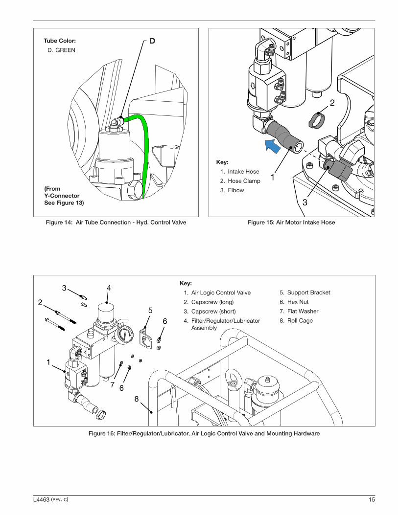
3. Disconnect pump air tubes at locations “A”, “B”, “C” and “D” as shown in Figure 13 and Figure 14.
Collar
Connected
Disconnected
Important: Push and hold collar inward while disconnecting or connecting air tube.
Figure 12: Air Tube Connections
Tube Color:
A. BLACK
B. RED
C. GREEN
A
B
C
(See Figure 14)
Figure 13: Air Tube Connections - Air Logic Control Valve.
NOTICE See Figure 12 for air tube connection details. To release each air tube, firmly press down on the connector collar and pull the air tube outward. Disconnect tubes only at locations shown. Tubes are color coded for identification purposes.
4. Remove two capscrews securing the filter/regulator/lubricator assembly to the roll cage. See Figure 16.
5. Remove two capscrews securing the support bracket to the roll cage. See Figure 16.
6. Remove hose clamp and intake hose from elbow at air motor intake port. See Figure 15.
7. Remove the filter/regulator/lubricator assembly and the air logic control valve from the roll cage as a complete unit.
NOTICE Set aside this sub-assembly. It will be reinstalled during reassembly procedures.
L4463 (rev. c) 15
Tube Color:
D. GREEND
(From Y-Connector See Figure 13)
Figure 14: Air Tube Connection - Hyd. Control Valve
Figure 16: Filter/Regulator/Lubricator, Air Logic Control Valve and Mounting Hardware
3
2
6
65
8
7
1
4Key:
1. Air Logic Control Valve
2. Capscrew (long)
3. Capscrew (short)
4. Filter/Regulator/Lubricator Assembly
5. Support Bracket
6. Hex Nut
7. Flat Washer
8. Roll Cage
2
1
3
Key:
1. Intake Hose
2. Hose Clamp
3. Elbow
Figure 15: Air Motor Intake Hose

16 L4463 (rev. c)
2
3
1
Key:
1. Roll Cage
2. Capscrews
3. Pump
Figure 17: Pump and Roll Cage
8. Remove four capscrews securing the roll cage to the hydraulic reservoir. See Figure 17.
9. Carefully position the pump through the open side of the roll cage until it is completely removed. It will be necessary to tilt the pump slightly so that the lifting eyebolt clears the roll cage structure. After removal, place the pump on a stable and secure work surface.
10. Remove the capscrews and washers securing the pump cover plate.
11. Connect hoist and sling to eyebolt. Carefully lift the pump assembly off of the hydraulic reservoir as a complete unit. See Figure 18.
1
2
3
4
5
Key:
1. Capscrew
2. Gasket
3. Pump Assy.
4. Reservoir Gasket
5. Hyd. Reservoir
Figure 18: Pump Assembly and Hyd. Reservoir
NOTICE Refer to Figure 19 during steps 12 through 15.
12. Inspect the reservoir interior. Using a clean lint free cloth, remove any dirt or sludge from interior surfaces.
13. Inspect the pump element for obvious signs of wear or damage. Verify that there are no loose components. Remove any dirt or sludge from pump element exterior surfaces and the underside of the pump cover plate.
14. Using a clean lint free rag, wipe the oil intake filter and remove any dirt or sludge. Replace filter if clogged or damaged.
15. Inspect the high pressure tube connecting the pump element to the hydraulic control valve manifold. Tighten any loose fittings. Replace high pressure tube if leaking or damaged.
16. Inspect the reservoir gasket. Replace it with a new gasket if worn or damaged. See Figure 18.

L4463 (rev. c) 17
1
653
4
2
Key:
1. Pump Element
2. Heat Exchanger
3. Oil Bypass Hose
4. Oil Intake Filter
5. High Pressure Tube
6. Oil Return Tube
Figure 19: Inspection and Cleaning - Pump Element
17. After cleaning is completed, reassemble the pump assembly to the hydraulic reservoir, following steps 8 through 11 of this procedure in reverse order. Apply Loctite 243 thread sealant to all cover plate mounting bolts and torque them to 60-75 lb-in [6.8-8.5 Nm]. See Figure 18.
18. Carefully position the pump through the open side of the roll cage until it is positioned inside. It will be necessary to tilt the pump slightly so that the lifting eyebolt clears the roll cage structure.
19. Secure the hydraulic reservoir to the roll cage with four capscrews. Apply Loctite 243 thread sealant to capscrews and torque them to 11-13 ft-lbs [14.9-17.6 Nm]. See Figure 17.
NOTICE Attach the intake hose first, before securing the filter/regulator/lubricator to the roll cage. This will make it easer to attach the hose.
20. Position the filter/regulator/lubricator assembly inside the roll cage. Attach the air motor intake hose to the elbow at the air motor intake port. Secure with new hose clamp. See Figure 15.
21. Secure the filter/regulator/lubricator assembly to the roll cage with two screws, flat washers and hex nuts. Apply Loctite 243 to screw threads and torque to 55-65 in-lbs [6.2-7.3 Nm]. See Figure 16.
22. Secure the support bracket to the roll cage. with two screws and hex nuts. Apply Loctite 243 to screw threads and torque to 55-65 in-lbs [6.2-7.3 Nm]. See Figure 16.
23. Reconnect the pump air tubes at locations “A”, “B”, “C” and “D”. See Figure 13 and Figure 14.
24. Refill the hydraulic reservoir and check for leaks as described in steps 7 through 14 of Section 9.1.
9.3 Air Exhaust Muffler
The pump is equipped with an air exhaust muffler that helps maintain quiet pump operation. See Figure 20.
Always shut off compressed air supply and disconnect air supply hose from pump before performing any maintenance or repairs on the muffler.
Periodically check the muffler bowl for condensate accumulation. If condensate is present, open the drain port at the bottom of the bowl and allow the condensate to drain into a pan or container.
The muffler contains two reusable 5 micron elements. Clean or replace these elements if they become clogged.
Contact the muffler manufacturer for detailed maintenance and replacement parts information.
NOTICE A heavy oil film in the exhausted air may indicate that the amount of oil supplied by the pump air lubricator needs to be reduced. Refer to Section 6.7 for additional information.
3
2
1
PRESS
TURN
Key:
1. Exhaust Vent
2. Muffler Bowl
3. Drain Port
Figure 20: Air Exhaust Muffler

18 L4463 (rev. c)
9.4 Air Filter/Regulator Maintenance
CAUTION Always shut off compressed air supply and disconnect air supply hose from pump before removing the air filter bowl or air lubricator bowl for any reason. Failure to follow this instruction will result in the uncontrolled release of pressurized air. Minor or moderate personal injury could result.
CAUTION Stay clear of air filter bowl drain while compressed air supply is connected. Drain will open automatically as needed and will release condensate under pressure.
See Figure 21.
• The air filter bowl is automatically drained when condensate reaches a pre-defined level. A G1/8" fitting is provided at the drain port. A drain tube (user supplied) can be connected to this fitting if required to comply with local laws and regulations.
• Periodically check the air filter bowl for condensate. If condensate level rises above the MAX mark on the filter bowl housing, it is an indication that the filter element may be clogged and need replacement or that the drain port opening is obstructed.
• Replace air filter element (25μm particulate filter - located inside filter bowl) if it becomes dirty or clogged.
• Periodically clean the air filter bowl. USE MILD SOAP AND WATER ONLY! Do not use solvents or chemicals to clean the bowl.
• Replace the air filter bowl if it becomes damaged, crazed or cracked.
• Refer to the air filter/regulator manufacturer’s instructions for complete maintenance and replacement parts information.
Air Filter Bowl
1
2
7
6
35
4
8
MIN
MIN
MAX
MAX
Condensate Drain Port with G1/8" connection (auto-draining)
Figure 21: Air Filter Bowl Details
9.5 Air Lubricator Maintenance
CAUTION Always shut off compressed air supply and disconnect air supply hose from pump before removing the air lubricator bowl for any reason. Failure to follow this instruction will result in the uncontrolled release of pressurized air lubricant oil. Minor or moderate personal injury could result.
See Figure 22.
• Periodically check the oil level in the air lubricator bowl. When it drops to the lowest of the bowl’s four windows, remove lubricator fill plug and add additional air lubricant oil. Refer to Section 6.6 for air lubricant oil specifications and filling procedure.
• To prevent premature wear and possible damage to the pump air motor, add air lubricant oil immediately if the oil level drops below the MIN mark on the air lubricator bowl housing.
• Air lubricant oil can be added directly to the air lubricator bowl if desired. However, to avoid pressurized oil splash, always shut off compressed air supply and disconnect air supply hose before removing the bowl (see Caution statement at beginning of this section).
• Periodically clean the air lubricator bowl. USE MILD SOAP AND WATER ONLY! Do not use solvents or chemicals to clean the bowl.
• Replace the air lubricator bowl if it becomes damaged crazed or cracked.
• Refer to the air lubricator manufacturer’s instructions for complete maintenance and replacement parts information.
1
2
7
6
35
4
8
MIN
MIN
1
2
7
6
35
4
8
MIN
MIN
MAX
MAX
LOW OIL!
Air Lubricator Bowl
Figure 22: Air Lubricator Bowl Details

L4463 (rev. c) 19
Troubleshooting Chart
Symptom Possible Cause Solution
1. Pump will not start. a. Compressed air system turned off or air supply line blocked.
Turn on compressed air system. Verify that gauge on pump air filter/regulator indicates pressure.
b. Low air pressure and/or flow. Increase air pressure as required. Verify that compressed air system is capable of producing the minimum required pressure and flow. Refer to Section 3.1.
c. Air logic control valve malfunction. Check for proper operation of the air logic control valve. Replace if required.
d. Mechanical damage to pump element and/or air motor.
Troubleshoot pump air motor and pump element components to determine cause. Check pendant controls and air lines.
2. Pump stops under load. a. Low air pressure. or Minimum required air flow rate is
insufficient.
Increase air pressure as required.
Use a larger diameter air supply line and/or adequate air source.
b. Air muffler clogged by ice or dirt. Check air muffler exhaust vent. Remove ice if present.
Replace air muffler elements if clogged. Refer to air muffler manufacturer’s instructions and parts lists.
c. Pump bypass valve out of adjustment or malfunctioning.
Readjust or repair pump bypass valve.
d. Mechanical damage to pump element and/or air motor.
Troubleshoot pump air motor and pump element components to determine cause.
3. Pump fails to build pressure or builds less than full pressure.
a. User-adjustable relief valve open or set too low.
Increase relief valve pressure setting. Refer to Section 8.5.
b. Air in the hydraulic system. Perform air removal procedure. Refer to Section 8.4.
c. External leak in the hydraulic system.
Check entire hydraulic system for leaks. Tighten, repair or replace components as required.
d. Oil needs changing. Pump oil intake filter clogged.
Drain, clean and inspect the hydraulic reservoir per instructions in Sections 9.1 and 9.2. Remove any dirt or sludge. Clean or replace the oil intake filter.
e. Internal leak in hydraulic control valve or pump element. Worn or damaged internal components.
Troubleshoot hydraulic control valve and pump element components. Tighten, repair or replace components as required.
4. Low oil flow. a. Low air pressure and/or flow. Increase air pressure as required. Verify that compressed air system is capable of producing the minimum required pressure and flow. Refer to Section 6.4.
b. Dirty air filter element. Replace filter element inside the air filter/lubricator. Refer to filter/lubricator manufacturer’s instructions and parts lists.
c. Internal leak in hydraulic control valve or pump. Worn or damaged internal components.
Troubleshoot hydraulic control valve and pump element components. Tighten, repair or replace components as required.
d. Oil needs changing. Pump oil intake filter clogged.
Drain, clean and inspect the hydraulic reservoir per instructions in Section 9.1 and Section 9.2. Remove any dirt or sludge. Clean or replace the oil intake filter.
(continued on next page)
10.0 TROUBLESHOOTING
Only qualified hydraulic maintenance personnel with appropriate skills and training should be permitted to service the pump or system components. The Troubleshooting Chart is not all inclusive but is intended to be used as a guide to help diagnose and resolve the most common problems which may occur.

20 L4463 (rev. c)
Troubleshooting Chart (continued)
Symptom Possible Cause Solution
5. Torque wrench advances or retracts erratically.
a. Air in the hydraulic system. Advance and retract the torque wrench until operation is smooth. Refer to Section 8.4.
b. Low air pressure and/or flow. Increase air pressure as required. Verify that compressed air system is capable of producing the minimum required pressure and flow. Refer to Section 3.1.
c. External leak in hydraulic system. Check entire hydraulic system for leaks. Tighten, repair or replace components as required.
d. Torque wrench internal leakage. Worn or damaged internal components.
Troubleshoot torque wrench.
Tighten, repair or replace components as required.
Refer to torque wrench manufacturer’s repair and overhaul instructions.
e. Internal leak in hydraulic control valve or pump element. Worn or damaged internal components.
Troubleshoot pump hydraulic control valve and pump element.
Tighten, repair or replace components as required.

NOTES
_______________________________________________________________________________________
_______________________________________________________________________________________
_______________________________________________________________________________________
_______________________________________________________________________________________
_______________________________________________________________________________________
_______________________________________________________________________________________
_______________________________________________________________________________________
_______________________________________________________________________________________
_______________________________________________________________________________________
_______________________________________________________________________________________
_______________________________________________________________________________________
_______________________________________________________________________________________
_______________________________________________________________________________________
_______________________________________________________________________________________
_______________________________________________________________________________________
_______________________________________________________________________________________
_______________________________________________________________________________________
_______________________________________________________________________________________
_______________________________________________________________________________________
_______________________________________________________________________________________
_______________________________________________________________________________________
_______________________________________________________________________________________
_______________________________________________________________________________________
L4463 (rev. c) 21

NOTES
_______________________________________________________________________________________
_______________________________________________________________________________________
_______________________________________________________________________________________
_______________________________________________________________________________________
_______________________________________________________________________________________
_______________________________________________________________________________________
_______________________________________________________________________________________
_______________________________________________________________________________________
_______________________________________________________________________________________
_______________________________________________________________________________________
_______________________________________________________________________________________
_______________________________________________________________________________________
_______________________________________________________________________________________
_______________________________________________________________________________________
_______________________________________________________________________________________
_______________________________________________________________________________________
_______________________________________________________________________________________
_______________________________________________________________________________________
_______________________________________________________________________________________
_______________________________________________________________________________________
_______________________________________________________________________________________
_______________________________________________________________________________________
_______________________________________________________________________________________
22 L4463 (rev. c)

L4463 (rev. c) 23
NOTES
_______________________________________________________________________________________
_______________________________________________________________________________________
_______________________________________________________________________________________
_______________________________________________________________________________________
_______________________________________________________________________________________
_______________________________________________________________________________________
_______________________________________________________________________________________
_______________________________________________________________________________________
_______________________________________________________________________________________
_______________________________________________________________________________________
_______________________________________________________________________________________
_______________________________________________________________________________________
_______________________________________________________________________________________
_______________________________________________________________________________________
_______________________________________________________________________________________
_______________________________________________________________________________________
_______________________________________________________________________________________
_______________________________________________________________________________________
_______________________________________________________________________________________
_______________________________________________________________________________________
_______________________________________________________________________________________
_______________________________________________________________________________________
_______________________________________________________________________________________

www.enerpac.com
© 2020 Enerpac, All Rights Reserved.