zadara storage cloud vpsa user guide 14.11 - amazon s3 · zadara!storage!cloud!!...
TRANSCRIPT

VPSA User Guide Page 1
March 2015
Revision C © 2011–2015 ZADARA Storage, Inc. All rights reserved.
Zadara Storage Cloud
VPSA User Guide 14.11

VPSA User Guide Page 2
Contents 1 Preface .............................................................................................................................................. 5
1.1 Intended Audience ................................................................................................................ 5 1.2 Document History ................................................................................................................. 5
2 Introduction ..................................................................................................................................... 5 2.1 VPSA Components ............................................................................................................... 5
2.1.1 VPSA Provisioning Portal .......................................................................................... 5 2.1.2 Virtual Controller .......................................................................................................... 5 2.1.3 Dedicated Drives ............................................................................................................ 5
3 Getting Started ............................................................................................................................... 6 3.1 Registering a Zadara Account & Creating a VPSA ................................................... 6 3.2 The VPSA Interface ............................................................................................................. 8 3.3 Creating RAID Group, Pools, and Volumes ............................................................... 9
4 Provisioning your VPSA ............................................................................................................ 9 4.1 Adding and removing Disk Drives .................................................................................. 9 4.2 Managing Zadara Engines ................................................................................................ 10 4.3 Assigning Public IPs .......................................................................................................... 12 4.4 Adjusting Cache ................................................................................................................... 12 4.5 Hibernating your VPSA .................................................................................................... 13
5 Managing RAID Groups and Drives .................................................................................... 14 5.1 Creating a RAID Group .................................................................................................... 14
5.1.1 Understanding RAID levels ..................................................................................... 15 5.2 Viewing RAID Group properties ................................................................................... 16 5.3 Understanding Hot Spare Drives ................................................................................... 18 5.4 Managing RAID Group Sync Speed ............................................................................. 18 5.5 Understanding Media Scans ............................................................................................ 19 5.6 Force Recovery .................................................................................................................... 19 5.7 Replacing a Drive ................................................................................................................ 20 5.8 Shredding a Drive ............................................................................................................... 21 5.9 Viewing Drive properties ................................................................................................. 21
6 Configuring Storage Pools ....................................................................................................... 22 6.1 Understanding Storage Pools .......................................................................................... 22 6.2 Creating and Managing Pools ......................................................................................... 23 6.2.1 Creating a Pool ............................................................................................................ 23 6.2.2 Expanding Pool Capacity ........................................................................................ 24 6.2.3 Disabling SSD cache on a pool .............................................................................. 25

VPSA User Guide Page 3
6.3 Viewing Pool properties .................................................................................................... 25 7 Understanding Controllers ................................................................................................... 29 7.1 Failover .................................................................................................................................. 30 7.2 NFS Domain ......................................................................................................................... 30 7.3 Public IPs .............................................................................................................................. 30 7.4 Recycle Bin ........................................................................................................................... 30 7.5 SMB Charset ........................................................................................................................ 30 7.6 Encryption ............................................................................................................................ 30 7.7 Download Metering DB .................................................................................................. 30
8 Managing Servers ..................................................................................................................... 31 8.1 Adding a Server .................................................................................................................. 31 8.1.1 Adding a Server automatically ............................................................................. 31 8.1.2 Adding a Server manually ...................................................................................... 33 8.1.3 Configure Server Attributes .................................................................................. 38
8.2 Viewing Servers Properties .......................................................................................... 38 9 Managing Volumes, Snapshots and Clones .................................................................... 40 9.1 Creating and Deleting a Volume ................................................................................. 41 9.2 Attaching & detaching Volumes to Servers ............................................................ 44 9.3 Expanding a Volume ........................................................................................................ 46 9.4 Migrating a Volume .......................................................................................................... 46 9.5 Managing Snapshots and Snapshot Policies .......................................................... 48 9.5.1 Manual creation & deletion of Snapshots ....................................................... 48 9.5.2 Managing Snapshot Policies ................................................................................. 48
9.6 Cloning a Volume ............................................................................................................... 51 9.7 Managing Encrypted Volumes ..................................................................................... 53 9.8 Viewing Volume Properties .......................................................................................... 54 9.9 Filtering Snapshots ........................................................................................................... 57
10 Managing Access Control .................................................................................................... 58 10.1 Adding & Deleting Users .............................................................................................. 58 10.2 Managing User Passwords .......................................................................................... 59 10.3 Managing NAS Users Access Control ..................................................................... 61 10.3.1 Creating NAS Users ................................................................................................ 61 10.3.2 Creating SMB Users ................................................................................................ 62 10.3.3 Editing SMB Users Password ............................................................................. 63
10.4 Creating NAS Groups ..................................................................................................... 63 10.5 Enabling Active Directory Authentication ........................................................... 64

VPSA User Guide Page 4
10.5.1 Joining the VPSA to Active Directory ............................................................. 64 10.5.2 Changing Active Directory DNS ........................................................................ 65 10.5.3 Leaving an Active Directory ............................................................................... 65
11 Managing Remote Mirroring ............................................................................................. 66 11.1 Creating a Local Mirror ................................................................................................ 67 11.2 Connect to a remote VPSA .......................................................................................... 68 11.3 Viewing remote VPSA Properties ............................................................................ 69 11.4 Creating a Remote Mirror ........................................................................................... 70 11.5 Replicate the same volume to multiple destinations ...................................... 72 11.6 Pause & Continue Remote Mirror ........................................................................... 72 11.7 Managing Mirror Lifecycle ......................................................................................... 73 11.7.1 Clone Destination Volume for Dev & Test of Remote Mirror .............. 73 11.7.2 Breaking a Mirror ................................................................................................... 74 11.7.3 Reconnecting a Mirror .......................................................................................... 74
11.8 Viewing Remote Mirror Properties ........................................................................ 76 12 Managing TechSupport Tickets ....................................................................................... 79

VPSA User Guide Page 5
1 Preface This documentation presents information specific to Zadara Storage products.
1.1 Intended Audience
This document is intended for end users and storage administrators who wish to consume Enterprise Storage-‐as-‐a-‐Service via the Zadara Storage VPSA service.
1.2 Document History
Date Revision Description
November 2013 A Initial revision for V2.0 Release Updated to version 13.10 content
February 2014 B Updates for Release 14.01
March 2015 C Updates for Release 14.11
2 Introduction Virtual Private Storage Array (VPSA) is the first Software Defined, Enterprise Storage-‐as-‐a-‐Service. It is an elastic and private Block and File Storage System which provides Enterprise-‐grade data protection and data management storage services. As the VPSA Administrator, you will appreciate the level of control you have over the storage system while leveraging the benefits of consuming it as a service.
2.1 VPSA Components
2.1.1 VPSA Provisioning Portal The VPSA Provisioning Portal is the your gateway to the Zadara Storage ecosystem through which you can create, view, and modify your VPSA configurations on the many different Clouds that Zadara Storage offers.
2.1.2 Virtual Controller A Virtual Controller (VC) is a Virtual Machine with dedicated CPUs & RAM, which runs the VPSA IO stack and control stack. Two VCs are paired in an Active-‐Standby pair for high availability. The VC maintains a sophisticated and granular block-‐level mapping layer from virtual to physical address spaces, thus enabling enterprise-‐level data management capabilities like Thin Provisioning, Snapshots, Cloning and Remote Mirroring. The VCs provide GUI and REST API end points for management and control.
2.1.3 Dedicated Drives The Zadara Storage Cloud Orchestrator assigns dedicated drives per VPSA. The drives are provisioned from different Storage Nodes (SNs) for maximum

VPSA User Guide Page 6
redundancy and performance. Each drive is exposed as a separate iSCSI target from the SN and is LUN masked only to the VPSA’s VCs. This provides a complete isolation and privacy of your data drives. No neighbor can access your drives, impact your performance, or compromise your privacy and security. Hence, your QoS is guaranteed.
3 Getting Started This chapter contains step-by-step instructions to create a VPSA and then to configure its storage properties
3.1 Registering a Zadara Account & Creating a VPSA
• Go to https://manage.zadarastorage.com/register/ and complete the form to register a Zadara Account.
• Go to your VPSA Provisioning Portal at https://manage.zadarastorage.com, Login using the registered username\email & password, and press "Create VPSA." The following dialog will appear:

VPSA User Guide Page 7
Enter the following mandatory fields:
• VPSA Name – Give the VPSA a name. This is how it will appear in the Cloud Console and in the VPSA GUI.
• VPSA Description – Give the VPSA a description. • Select Cloud Provider – From the VPSA Provisioning Portal you can
provision and manage VPSAs across many Cloud Providers & regions. o Select a Region – Select the Cloud Provider region where your
application servers reside. The servers and the VPSA must reside in the same region in order to establish efficient iSCSI or NFS\CIFS connectivity.
• Select the Zadara Engine – The Zadara Engine defines the compute characteristics of your VPSA's Virtual Controllers (VCs). Each engine type defines the following characteristics:
o Number of CPUs that are assigned to your VPSA's VCs. o Amount of RAM that is assigned to your VPSA's VCs. o Default size of protected SSD Cache.
The Zadara Engine type can be changed at any time throughout the lifetime of your VPSA depending on your application’s needs. Note: The compute resources (CPU, RAM and Cache) are dedicated to your VPSA, which ensures consistent performance and isolation from other tenants workloads and behavior.
• Drive Quantities – Select the type and number of drives that are to be allocated for your VPSA.
o The Zadara Cloud Orchestrator allocates dedicated drives. o Drives are allocated from as many different SNs as possible to
provide max redundancy for your VPSA's RAID groups. o There is a maximum of number of drives per Zadara Engine type.
The larger the Engine is, the more drives you can add. The following is the max drives per Engine type:
Engine Type Maximum # of drives Baby 5 Basic 10 Boost 20 Blazing 40 Blazing+ 80
• Once you have completed selecting the above VPSA characteristics, press
the Submit button to confirm the VPSA creation request. The requested VPSA will appear in the “Awaiting Approval” list.
• VPSA creation requires the approval of a Zadara Storage Cloud admin. Once approved, the new VPSA only takes a few minutes to launch. During that time you'll see your VPSA in "Launching" status as shown below:

VPSA User Guide Page 8
• Once the VPSA is ready, you’ll receive an email with a temporary passcode at your registered email address.
• Use the "Management Address" link to access the VPSA GUI:
• Use your registered username or email address, and the temporary
passcode, to enter the VPSA GUI. You will be immediately prompted to set a new password for your VPSA User account.
3.2 The VPSA Interface
The VPSA GUI provides full management and control of your VPSA. It contains the following main components (as numbered in the above screenshot):
1. Main navigation left panel – Traverse through the various VPSA entities. The selected entity is highlighted.

VPSA User Guide Page 9
2. The center pane – Displays a list of objects from the selected entity type (e.g., drives in the above screenshot example), and for each object it displays the main properties.
3. The south pane – Displays detailed information regarding the selected object. All objects have at least 3 tabs:
a. Properties – Detailed properties of the object. b. Metering – Typically IO workload metering info. c. Logs – List of event-‐log messages related to that object.
4. Enterprise Suite enabled\disabled – Indicated at the top-‐right corner. 5. Logged-‐in username – Displayed at the bottom left corner. 6. Selected Language – Displayed at the top left corner . You can use this
drop down to change the displayed language.
3.3 Creating RAID Group, Pools, and Volumes
• Create a Raid Group to define the level of data protection needed. For more details check here.
• Create a storage Pool by using aggregated capacity from RAID Groups. For more details check here.
• Create an iSCSI\NFS\SMB Thin Provisioned Volume to be used by your servers. For more details check here.
• Attach the Volume to a Server. For more details check here. Congratulations! You have a new VPSA provisioned and ready. The following sections describe in detail the various capabilities and services of your VPSA.
4 Provisioning your VPSA You create, delete, and manage the resources composing your VPSAs via the VPSA Provisioning Portal. This section describes the available operations at the Provisioning Portal (https://manage.zadarastorage.com).
4.1 Adding and removing Disk Drives
To add drives to your VPSA, go to the VPSA Management Console, select the VPSA, and then press the Add drives button.

VPSA User Guide Page 10
• Select the number of drives from each available drive type you wish to
add to your VPSA, and press Submit. • This operation requires the approval of a Zadara Storage Cloud Admin.
Once approved, you'll see the number of drives in the VPSA Management Console update accordingly, and if you refresh the Drives page in the VPSA GUI, the new drives will be displayed.
You remove unused drives (in status "Available") from within the VPSA. Go to the VPSA GUI -‐> Drive page, select the drive you wish to remove, and press the Remove button:
If you wish to remove a drive which is part of a RAID Group, you first need to replace it with another drive, as described here.
4.2 Managing Zadara Engines
The Zadara Engine type defines the following characteristics of your VPSA’s Storage Controllers:

VPSA User Guide Page 11
• Dedicated CPU and memory resources for your VPSA. Those resources are not shared with any other VPSA or tenant within the Zadara Storage Cloud.
• Protected SSD Cache Size -‐ Each VPSA is provisioned with an SSD Cache partition to be used for both metadata and read/write caching. The SSD cache partition is protected using RAID-‐1, where each mirror copy resides on a different SN, thus ensuring Cache resilience to SN failure. Each Engine type comes with a default SSD Cache partition size. You can request additional SSD capacity for caching. For more details see “Adjusting Cache.”
• Maximum number of drives – The maximum number of drives which can be allocated to the VPSA.
The following Zadara Engines are available: Zadara Engine Type
Dedicated compute resources
Protected SSD Cache Size (Mirror-‐1)
Maximum # of drives
Baby 2 CPU, 4 GB RAM 20 GB 5 Basic 4 CPU, 8 GB RAM 20 GB 10 Boost 6 CPU, 16 GB RAM 40 GB 20 Blast 8 CPU, 24 GB RAM 60 GB 40 Blazing 10 CPU, 32 GB RAM 80 GB 80 Blazing+ 16 CPU, 32 GB RAM 80 GB 80
To change the Zadara Engine type, press the Change Engine button in the VPSA Provisioning Portal:
This operation requires the approval of the Zadara Storage Cloud Admin. The Zadara Engine upgrade\downgrade process may take a few minutes. During that time, your VPSA status will change to "Upgrade Pending."

VPSA User Guide Page 12
When the process completes the VPSA status will change back to "Ready."
4.3 Assigning Public IPs
For security and privacy reasons, by default you cannot access the VPSA from the public Internet. The VPSA FrontEnd IP address, used for VPSA management (via GUI and REST API) and for data IO workload (via iSCSI\NFS\SMB protocols), is allocated on the Zadara Storage Cloud "Front-‐End" network 10GbE interface which is routable only from the Cloud Servers network. Servers outside of your Cloud Servers network cannot reach this IP address. This means you cannot access your VPSA GUI from the Internet. A typical use case requiring Public IP addresses is when you’re doing Asynchronous Remote Mirroring between two VPSAs in different regions, or even different Cloud Providers for Disaster Recovery (DR). Communication between the VPSAs is done via an authenticated and encrypted channel over the public Internet, thus requiring Public IPs. To assign a Public IP address to your VPSA, go to the VPSA Management Console and press the Assign Public IP button. You can see the assigned IP address in your VPSA details in the VPSA Management Console and in the VPSA GUI, under Controller-‐>Public IPs. To remove it, simply click the Remove Public IP button in the VPSA Management Console. Notes:
• Access to the VPSA GUI and API is blocked through the Public IP for security reasons.
• NATed Servers are not supported for iSCSI, NFS, and SMB protocols over the Public IP.
4.4 Adjusting Cache
Each VPSA is provisioned with an SSD cache partition, which is utilized by the VPSA for both metadata and read/write caching. The SSD cache partition is protected using RAID-‐1, where each mirror copy resides on a different SN thus ensuring cache resilience to multiple types of failure. The VPSA SSD cache size is elastic, meaning that you can increase or decrease the SSD cache size based on your workload. The initially assigned default SSD cache size is also the minimal cache size for a given Zadara Engine. The default and maximum SSD Cache size depends on the Engine type: Zadara Engine Default SSD Cache Size Max SSD Cache Size Baby 20 GB 80 GB Basic 20 GB 80 GB

VPSA User Guide Page 13
Boost 40 GB 160 GB Blast 60 GB 240 GB Blazing 80 GB 320 GB Blazing+ 80 GB 320 GB
To change the SSD Cache size for your VPSA, go to the VPSA Management Console and press the Adjust Cache button:
4.5 Hibernating your VPSA
You can hibernate your VPSA when it is not in use for some period of time in order to reduce its associated service cost. Hibernating a VPSA involves the process of deleting its Virtual Controllers (the VPSA) while maintaining the data drives and all the necessary metadata to resume its operation at a later stage. No data is lost! The hibernated VPSA is not accessible to any GUI or REST API commands, nor will it present any iSCSI or NFS\SMB volumes. While the VPSA is in a hibernated state you will only be billed for the drives, not the engine. Resuming a hibernated VPSA only takes a few minutes. To hibernate a VPSA, go to the VPSA Provisioning Portal and press the Hibernate button:

VPSA User Guide Page 14
To resume access to the VPSA, go to the VPSA Management Console and press the Restore button.
5 Managing RAID Groups and Drives
5.1 Creating a RAID Group
VPSA RAID Groups define the level of protection and can impact the performance of your data according to the selected RAID-‐level, number of drives, and type of drives. RAID groups span across drives from different Storage Nodes. Thus, a RAID Group is resilient to a single drive failure (RAID-‐6 allows for a 2 drive failure), as well as to a complete Storage Node failure. Define the following attributes in the “Create RAID Group” dialog box:
• Enter the RAID Group name (you will later add it to a Pool so you may want to provide a meaningful name that describes the target usage of the Pool).
• Select Protection Type. See the below description for the various RAID levels.
• Select whether to allocate a drive as a Hot Spare for this RAID group. See more details about managing Hot Spares here.
• Select the drives that participate in the RAID Group. As noted below, for RAID-‐1 a minimum of 2 drives is required, for RAID-‐5 a minimum of 3 drives, and for RAID-‐6 a minimum of 4 drives.
• For maximum redundancy, drives MUST be selected from different Storage Nodes (VPSA will prevent you from doing otherwise).

VPSA User Guide Page 15
• It is possible but not recommended to mix drives of different types in a RAID Group.
• You cannot place drives larger than 1TB into a RAID5 group.
5.1.1 Understanding RAID levels
RAID level Description
RAID-‐1 – Mirroring
Offers an excellent combination of data protection and performance. RAID-‐1, or Drive Mirroring, creates fault tolerance by storing duplicate sets of data on a minimum of two hard drives. There must be 2 or 3 drives in a RAID-‐1. RAID-‐1 and RAID-‐10 are the most costly fault tolerance methods because they require 50 percent of the drive capacity to store the redundant data. RAID-‐1 mirrors the contents of one hard drive in the group onto another. If either hard drive fails, the other hard drive provides an additional copy of the files, and normal system operations are not interrupted.
RAID-‐5 Offers a combination of data protection and usable capacity, while also improving performance over RAID-‐6. RAID-‐5 stores parity data across all the physical drives in the array and allows more simultaneous read operations and higher performance. If a drive fails, the controller uses the parity data and the data on the remaining drives to reconstruct data from the failed drive. The system continues operating with a slightly reduced performance until you replace the failed drive. RAID 5 can only withstand the loss of one drive without total array failure. It requires an array with a minimum of three physical drives. Usable capacity is N-‐1, where N is the number of physical drives in the logical array.

VPSA User Guide Page 16
RAID-‐6 Offers the best data protection and is an extension of RAID-‐5. RAID-‐6 uses multiple parity sets to store data and can therefore tolerate up to 2 drive failures simultaneously. RAID-‐6 requires a minimum of 4 drives. Performance is slightly lower than RAID-‐5 due to parity data updating on multiple drives. Usable capacity is N-‐2 where N is the number of physical drives in the logical array.
RAID-‐10– Mirroring and Striping
Offers the best combination of data protection and performance. RAID-‐10, or drive mirroring, creates fault tolerance by storing duplicate sets of data on a minimum of four hard drives. RAID-‐10 is the most costly fault tolerance method because it requires 50 percent of the drive capacity to store the redundant data. RAID-‐10 first mirrors each drive in the array to another, and then stripes the data across the mirrored pair. If a physical drive fails, the mirror drive provides a backup copy of the files, and normal system operations are not interrupted. RAID 10 can withstand multiple simultaneous drive failures, as long as the failed drives are not mirrored to each other. Note: RAID-‐10 is achieved in a VPSA by creating RAID-‐1 RAID Groups, and striping them together at the Pool level.
5.2 Viewing RAID Group properties
The following properties and metering information are displayed in the RAID-Group details, found in the south panel tabs: Properties Each RAID Group includes the following properties:
Property Description
ID An internally assigned unique ID.
Name User assigned name. Can be modified anytime.
Protection Selected RAID level—RAID-‐1, RAID-‐5 or RAID-‐6.
Capacity Total protected and usable capacity of the RAID Group.
Available Capacity
RAID Group usable capacity which is not allocated to any Pool.
Stripe Size Stripe size (per drive) for RAID-‐5 and RAID-‐6.
Mirror Number Number of mirror copies for RAID-‐1.
Protection Width Number of Drives participating in a RAID-‐5 and RAID-‐6

VPSA User Guide Page 17
RAID Group (including parity).
Status • Normal – All drives are in sync • Resyncing X% – The RAID is in an initial rebuild
process. • Degraded – One of the drives have failed. • Degraded Resyncing X% – The RAID is resyncing data
following a drive recovery\replacement. • Repairing X% – Media Scan is in progress. • Repairing Paused – Media Scan is paused. • Failed – The array has lost too many drives and
cannot serve Server IOs.
Created Date & time when the object was created.
Modified Date & time when the object was last modified. Drives Lists the disk Drives participating in the selected RAID Group. The following information is displayed per drive:
• Name • Location (Storage Node) • Capacity (in GB) • Type (SAS\SATA\SSD\TBD) • Status (Normal\Failed\TBD) • Hot Spare (Yes\No)
Metering The Metering Charts provide live metering of the IO workload associated with the selected RAID Group. The charts display the metering data as it was captured in the past 20 intervals. An interval length can be one of the following: 1 second, 1 minute, 10 minutes, or 1 hour. The Auto button lets you see continuously-‐updating live metering info. Note: The metering info of the RAID Group doesn't include RAID-‐generated IOs, such as when doing a rebuild. The following charts are displayed:
Chart Description
IOPs The number of read and write commands issued to the RAID Group per second.
Bandwidth (MB\s)
Total throughput (in MB) of read and write SCSI commands issued to the RAID Group per second.

VPSA User Guide Page 18
IO Time (ms) Average response time of all read and write SCSI commands issued to the RAID Group per selected interval.
Logs Displays all event logs associated with this RAID Group.
5.3 Understanding Hot Spare Drives
When creating a RAID Group, you can decide whether you’d like to allocate hot spare drives to the RAID Group or not. You can change this selection at any time by issuing “Add Spare” and “Remove Spare” on a selected RAID Group in the VPSA RAID Group GUI page. Allocating a hot spare drive for a RAID Group allows for immediate and automated drive replacement, with no human intervention, once the VPSA determines that the drive has failed. If you choose not to allocate a hot spare drive to your RAID group, you can still replace a Failed drive with any Available Drive not used in any other RAID Group within the VPSA. This process can be executed manually, or automated via the VPSA REST APIs. Simply identify the failed drive, issue the “Replace” command, and select the available drive to use for the replacement. For more details check here.
5.4 Managing RAID Group Sync Speed
RAID Group Sync Speed controls the rate with which data is synchronized during a RAID rebuild process, either on a newly created RAID group or following a drive replacement. Setting the Sync Speed is a tradeoff between the need to complete the RAID rebuild as quickly as possible in order to return to full redundancy level and the ability to supply good response time and throughput for application IOs. Therefore, the VPSA allows you to control two parameters impacting the sync Speed:

VPSA User Guide Page 19
• “Max Speed During Host I/Os” – Controls the RAID sync speed when there are Server IOs. Set it low if you want to prioritize the Servers IOs. Set it high if you’d like to prioritize the RAID rebuild process.
o Default value: 10 MB/s o Range: 1 -‐ 100 MB/s
• “Max Speed W/O Host I/Os” – Controls the sync speed when there are no Server IOs. Typically you would set it to max value (100 MB\s) unless it consumes too much of the VPSA resources (depending on the Engine type) impacting performance of other Raid Groups (which do have active Server IOs).
Sync Speed can be set and modified at any time and can vary between RAID groups. The Sync Speed also applies to Media Scan (see below).
5.5 Understanding Media Scans
Media Scan is the process of checking RAID-‐5 and RAID-‐6 parity integrity. It reads data and parity from all devices and automatically fixes any inconsistent parity. This process runs automatically once a month in order to identify and handle any possible silent data integrity issues. You may decide to trigger a media scan on a RAID Group, beyond this once-‐a-‐month scan, if there was an event that is suspected of risking data integrity, such as the failure of two or more drives in a RAID-‐5. RAID status will change to “Repairing X%” during the media scan. At the end of the media scan, it saves the results of the scan in an event-‐log message. Media scan cannot be aborted in the middle, but it can be paused. Press the Pause Media Scan button to pause the operation (the Media Scan button toggles to Pause Media Scan for RAID Groups which are in media scan). RAID status will change to “Repairing Paused” when the media scan is paused.
5.6 Force Recovery

VPSA User Guide Page 20
Force Recovery can be issued only on Failed RAID-‐5 and RAID-‐6 RAID Groups, after one or more of the failed drives have been recovered. If all the drives were recovered, the VPSA will have enough information to determine how to recover the RAID automatically, but if one drive is permanently gone in a RAID-‐5 RAID Group or two drives are permanently gone in a RAID-‐6 RAID Group the VPSA is unable to determine if the available drives contain the most up-‐to-‐date data and hence cannot safely decide to automatically recover the RAID Group. You can instruct the VPSA to perform a “Force Recovery” of the RAID Group, which marks all drives as consistent and in-‐sync, and moves the RAID to Normal state. It is recommended that you run Media Scan following Force Recovery, which will ensure RAID parity consistency (although data may still be inconsistent from the application perspective). Note: This operation may result in application data loss. It must be used only when drives are permanently lost and when there are no other alternatives to recover the data.
5.7 Replacing a Drive
Press the Replace button on the Drives page to replace a drive. When selecting the replacement drive you must choose a drive that will not break the RAID Group redundancy (i.e., you cannot have two or more drives from the same Storage Node in a RAID Group). If you select a drive that has a different type, or larger size than the other drives in the RAID Group, you will see a warning, but you can continue the operation. You can replace a drive in any RAID Group, whether the drive is healthy (Normal) or unhealthy (Failed).

VPSA User Guide Page 21
You cannot replace a drive if the RAID Group is in Resyncing state.
5.8 Shredding a Drive
Shredding is the process of erasing the data on a drive for security and privacy reasons by overwriting the entire drive with random data at least three times. Typically, you will shred a drive before returning it to the Zadara Cloud or before deleting your VPSA. Shredding is applicable only on drives in Available status (i.e., not in a RAID group). The Shredding progress appears in the drive status as "Shredding X%." A drive cannot be removed from a VPSA while it is being shredded. You need to either cancel the operation by pressing the Cancel Shred button, or wait till shredding is completed. Note: Shredding is irreversible!
5.9 Viewing Drive properties
You can view the following properties and metering information in the Drives Details south panel tabs: Properties Each drive includes the following properties: Property Description ID An internally assigned unique ID. Capacity Drive Capacity in MB. Storage Node The name of the Storage Node where the drive is physically
located. Type SATA, SAS, or SSD Status The drive's status reflects the drive health as sensed by the

VPSA User Guide Page 22
Storage Node and by the VPSA RAID logic: • Available – The drive is healthy and free. • Normal – The drive is healthy and belongs to a RAID
Group. • Absent – No access to the drive. • Failed – The Storage Node has reported failure
accessing the drive. • Faulty – The VPSA RAID object has failed writing or
reading from this drive. • Recover Pending – The RAID Group has failed and
the drive is awaiting recovery. • Shredding – The drive is being shredded.
RAID Group Name of the RAID group containing this drive. Protection Zone Displays the Protection Zone of the drive. Usage In-‐use., Available Added The date and time when the drive was added to the VPSA. Modified The date and time when the Drive object was last modified. Metering The Metering Charts provide live metering of the IO workload associated with the selected Drive. The charts display the metering data as it was captured in the past 20 “Intervals.” An Interval length can be one of the following: 1 Second, 1 Minute, 10 Minutes, or 1 Hour. The Auto button lets you see continuously-‐updating live metering info (refreshed every 3 sec). The Following charts are displayed:
Chart Description
IOPs The Number of Read and Write SCSI commands issued to the Drive per Second.
Bandwidth (MB\s)
Total throughput (in MB) of Read and Write SCSI commands issued to the Drive per Second.
IO Time (ms) Average response time of all Read and Write SCSI commands issued to the Drive per Selected interval.
Logs Displays all event logs associated with this Drive.
6 Configuring Storage Pools
6.1 Understanding Storage Pools

VPSA User Guide Page 23
Storage Pools are virtual entities managing storage provisioning from aggregated capacity of one or more RAID Groups, pooled into a single construct with some QoS attributes. Volumes are thinly provisioned, allocating capacity from the Pool only when needed. The Pool has an underlying block virtualization layer which maps virtual address space to physically allocated Pool space, and manages sharing of Pool physical chunks between Volumes, Snapshots and Clones. Snapshots and Clones consume zero capacity when they are created. They share the same data chunks as the Volume. Anytime you actually modify the data in the Volume, or in one of the Clones, the data chunk is being copied-‐on-‐write (COW) in order to apply the new written data without affecting the data set of the other objects sharing the same data chunk. Pools attributes define the way Volumes, Snapshots and Clones are provisioned.
6.2 Creating and Managing Pools
6.2.1 Creating a Pool To create a new Storage Pool, press either the Create button on the Pools page or the Create Pool button on the RAID Groups page. You will see the following dialog appear:
Select the Pool attributes:
• Display Name – Can be modified anytime later. • Raid Group(s) selection – Select one or more RAID Groups from which
protected storage capacity will be allocated for this Pool. • Capacity – The Pool's physical capacity in GB. By default, the capacity is
the aggregated capacities of all the selected RAID Groups, but you do not have to allocate full RAID Groups. If you define smaller capacity than is

VPSA User Guide Page 24
available in the selected RAID groups, the capacity will be evenly distributed between the RAID Groups.
• Type – The VPSA supports two types of Pools: Transactional & Repository Pools. The difference is the chunk size used for the mapping of virtual LBAs to Physical Drive addresses. The following table describes the tradeoff of each type and the recommended use cases:
Transactional Pool Repository Pool Chunk size
256KB 1MB
Pros • Faster COW operation • Space efficiency on
Random writes to Snapshots
• Smaller metadata size • Sequential workload
performance is similar to transactional Pools
Cons Increased metadata size • Slower COW operation. • Less space efficient
Use Case Transactional Workload with Snapshots
• Repository type workload. • Large Pools • Many snapshots to keep
• Cached – Use SSD to Cache Servers Reads and Writes.
o All Pools that are marked as "Cached" share the VPSA Cache. o Write Cache is mostly efficient on random writes intensive
workloads. o If the Pool consists of SSD drives, this option will be disabled.
• Striped – This check box is enabled only when you select two or more RAID Groups. Striping over RAID-‐1, RAID-‐5 and RAID-‐6 creates RAID-‐10, RAID-‐50 and RAID-‐60 type of configuration. Use striping to improve performance of random workloads since the IOs will be distributed and all drives will share the workload.
6.2.2 Expanding Pool Capacity To Expand the Pool, press the Expand button on the Pools page.

VPSA User Guide Page 25
You can expand a Pool using capacity from any RAID Group. If the RAID Group from which the new capacity is added doesn't match the protection type or drive type of the existing capacity, you’ll see a warning message pop up asking you to confirm the mismatch, which may impact the pool performance and protection QoS. It is possible to enable Caching on non-‐cached Pools. One use case to leverage this capability is to enable Caching only after the initial copy of the data into the VPSA. The initial copy typically generates sequential write IO workload, where non-‐cached Pools are most efficient. Once the initial copy is completed, enable caching on the Pool if you expect more random type of IO workload.
6.2.3 Disabling SSD cache on a pool
By default every pool is cached by the VPSA’s SSD cache. Disabling the cache will remove this feature.
6.3 Viewing Pool properties
The Pools details are shown in the following south panel tabs: Properties Each Pool includes the following properties: Property Description
ID An internally assigned unique ID.
Name User assigned name. Can be modified anytime.
Status • Normal • Creating • Deleting • Partial\Failed – At least one of the underlying
RAID groups is failed, or the Pool metadata cannot be initialized at Start Of the Day.
Capacity Total available capacity for user data & system metadata.
Available Capacity
Available (free) capacity to be used for User data. VPSA reserves 2% of the total Pool capacity for system metadata. If the VPSA needs more capacity for the metadata (very rare scenario), it will be consumed from

VPSA User Guide Page 26
the available capacity.
Metadata Capacity
Metadata Capacity
Free Capacity State
• Normal • Alert • Protected
Mode • Simple – There are one or more RAID Groups concatenated.
• Striped – There are two or more RAID Groups which are striped.
• Mixed – There are two or more RAID Groups which are concatenated and striped.
Type • Transactional Workloads • Repository Storage
Stripe Size Applicable only for Pools of Mode Striped (i.e., when data is striped between 2 or more RAID groups). The Stripe size is always 64KB.
Cached Yes\No – Indicates whether the Pool utilizes SSD for read\write caching
Raid Group(s) RAID Group name, or "Multiple (X)” where X denotes the number of RAID Groups in the Pool.
Created Date & time when the object was created.
Modified Date & time when the object was last modified. Capacity Alerts Alerts tab lists the Pool Protection Mechanism configurable attributes. See Managing Pool Alerts for more details. You can modify the following attributes:
• Alert Mode Threshold -‐ “Alert me when it is estimated that the Pool will be at full capacity in X Minutes.”
o Default Value: 360 minutes • Protection Mode Threshold -‐ “Do not allow new Volumes, Shares, or
Snapshots to be created when it is estimated that the Pool will be at full capacity in X Minutes.”
o Default Value: 60 minutes • Calculation Window -‐ “Calculate the estimated time until the Pool is full
based on new capacity usage in the previous X minutes.” o Default Value: 60 minutes
• Emergency Mode Threshold -‐ “Delete snapshots, starting from the oldest, when there is less than the following capacity left in the Pool”

VPSA User Guide Page 27
o Default Value: 5 GB Raid Groups This tab lists the RAID Groups participating in the selected Pool. Each RAID Group includes the following information:
• Name • Protection (RAID-‐1, RAID-‐5or RAID-‐6) • Status • Contributed Capacity
Volumes and Dest Volumes These two tabs provide two lists for the provisioned Volumes and the Provisioned Remote Mirroring Destination Volumes. Please note that the Dest volumes are not displayed in the main Volume page since most operations are not applicable on them. Displaying the list of the Dest Volumes in the Pools south panel provides a complete picture of the Objects consuming capacity from the Pool. Each Volume includes the following information:
• Name • Capacity (virtual, not provisioned) • Status • Data Type (Block or File-‐System)
Recycle Bin By default when a volume is deleted it is moved to a Pool’s Recycle Bin for 7 days until it is permanently deleted. From the Recycle Bin an administrator can purge (permanently delete) or restore a volume. Logs Displays all event logs associated with this Pool. Metering The Metering Charts provide live metering of the IO workload associated with the selected Pool. The charts display the metering data as it was captured in the past 20 “Intervals.” An Interval length can be one of the following: 1 Second, 1 Minute, 10 Minutes, or 1 Hour. The Auto button lets you see continuously-‐updating live metering info (refreshed every 3 sec). Pool Metering includes the following charts: Chart Description
IOPs The Number of Read and Write SCSI commands issued to the Pool per Second.
Bandwidth (MB\s)
Total throughput (in MB) of Read and Write SCSI commands issued to the Pool per Second.

VPSA User Guide Page 28
IO Time (ms) Average response time of all Read and Write SCSI commands issued to the Pool per Selected interval .
Pool Capacity Alerts The VPSA’s efficient and sophisticated storage provisioning infrastructure maximizes storage utilization while providing key enterprise-‐grade data management functions. As a result, you can quite easily over-‐provision a Pool with Volumes, Snapshots and Clones, and hence a Pool Protection Mechanism is required to alert and protect when free Pool space is low. The VPSA Pool Protection Mechanism is mostly time based. The goal is to provide you sufficient time to fix the low-‐free space situation by either deleting unused Volumes\Snapshots\Clones or by expanding the Pool available capacity (which is a very simple and quick process due to the elasticity of the VPSA and the Zadara Storage Cloud). The VPSA measures the rate at which Pool free space is consumed, and calculates the estimated time left before running out of free space. The following user-‐configurable parameters impact alerts and operations which are performed as part of the Pool Protection Mechanism:
• Capacity Threshold – The estimated time (in minutes) before running out of free space in which an online support ticket is to be submitted and an email to be sent to the VPSA user. When crossing this threshold, the Free Capacity State changes to “Alert” and the available capacity will be shown in Yellow. A secondary (“reminder”) ticket + email will be generated when the estimated time left is half of this threshold.
o Default: 360 minutes (6 hours) o Minimum: 1 minute
• Protection Threshold – The estimated time (in minutes) before running out of free space in which the VPSA starts blocking the creation of new Volumes, Snapshots and Clones on that Pool. A support ticket & email are generated as well. When crossing this threshold, the Free Capacity State changes to “Protect” and the available capacity will be shown in Red.
o Default: 60 minutes (1 hour) o Minimum: 1 minute
• Capacity consumption rate calculation window size -‐ the size of the
window (in minutes) that is used to calculate the rate at which free space is consumed. The smaller the window is, the more it is impacted by

VPSA User Guide Page 29
intermediate changes in capacity allocations which can result from changes in workload characteristics and\or creation\deletion of new Snapshots and Clones.
o Default: 60 minutes (1 hours) o Minimum: 1 minute
• Emergency Threshold – When the Pool’s free capacity drops below this
fixed threshold (in GB), the VPSA starts freeing Pool capacity by deleting older snapshots. The VPSA will delete one snapshot at a time, starting with the oldest snapshot until it exist the Emergency threshold (i.e, when free capacity is greater than the threshold). A support ticket & email are generated as well. When crossing this threshold, the Free Capacity State changes to “Emergency” and the available capacity will be shown in Red.
o Default: 5 GB o Minimum: 1 GB
Pool Performance Alerts A VPSA administrator has the option to set Pool Performance Alerts in addition to the default Pool Capacity Alerts. Alerts are available for – Read IOPS Limit – Alert when the average read IOPS during the past hour for a Pool exceeds some user specified threshold. Read Throughput Limit -‐ Alert when the average read MB/s during the past hour for a Pool exceeds some user specified threshold. Read Latency Limit – Alert when the average read latency during the past hour for a Pool exceeds some user specified threshold. Write IOPS Limit – Alert when the average write IOPS during the past hour for a Pool exceeds some user specified threshold. Write Throughput Limit -‐ Alert when the average write MB/s during the past hour for a Pool exceeds some user specified threshold. Write Latency Limit – Alert when the average write latency during the past hour for a Pool exceeds some user specified threshold.
7 Understanding Controllers Controller Objects in the VPSA represent the clustered controller pair of a VPSA.

VPSA User Guide Page 30
7.1 Failover
Failover fails the active controller and starts the passive controller with limited I/O interruption.
7.2 NFS Domain
Sets the domain name for NFS shares. This defaults to localdomain.
7.3 Public IPs
Displays any Public IPs assigned to the controllers.
7.4 Recycle Bin
Enables/Disables the recycle bin for the VPSA. This defaults to enabled. If the recycle bin is disabled then volumes that are deleted are immediately destroyed and cannot be recovered.
7.5 SMB Charset
Sets the default charset for SMB/CIFS volumes. If you plan to use filenames with different encoding in the filename (other than English), you may want to change the charset. The default value is UTF-‐8. Changing this value with clients connected will cause them to temporary lose access to all SMB shares.
7.6 Encryption
Sets the volume encryption password for the VPSA.
For more information on managing encrypted volumes see Section 9.8, Managing Encrypted Volumes.
7.7 Download Metering DB
The VPSA provides an option to download its performance metering database which contains per-‐minute performance statistics about all active and monitored Objects – Drives, Raid Groups, Pools, Volumes and Servers. The database is downloaded in a binary format and is accompanied with a tool (meter2csv) to convert the raw binary database to a cvs formatted file.
YOU MUST SAVE THIS PASSWORD FOR FUTURE USE. There is a small chance that our system will prompt you for this password in the future. If it does and you are unable to produce your password, YOU WILL PERMANENTLY LOSE ACCESS TO YOUR ENCRYPTED DATA and there would be NO WAY FOR US TO RECOVER YOUR DATA.

VPSA User Guide Page 31
8 Managing Servers Servers Objects in the VPSA represent Cloud Servers that consume VPSA Volumes. A Server needs to be properly defined and connected in order to access the VPSA Volumes via iSCSI, NFS or SMB\CIFS protocols.
8.1 Adding a Server
Establishing a connection between a Server and the VPSA involves the following steps:
• Creation of a Server Object in the VPSA database. • Setting the Server IQN for iSCSI connectivity and\or the server IP address
for NFS\SMB connectivity. • Establishing CHAP authentication handshake between the Server and the
VPSA for iSCSI. • Register Server OS information (optional).
8.1.1 Adding a Server automatically The VPSA automates the above steps for you via the “Connect Server” script. Go to Servers-‐>Add and select Automatic:
To Add a Windows Server:
• First time you connect an iSCSI Volume to a Windows Server, you need to start the iSCSI service on the Windows Server before running the VPSA connect script.
o In Windows Start-‐>Run dialog, type iSCSI and select the “iSCSI Initiator” program. You will be prompted to start the service. Press Yes to confirm:

VPSA User Guide Page 32
• On the VPSA GUI, Connect Server dialog, select platform: Windows. • Select the iSCSI checkbox if you wish to expose VPSA Block Volumes to
this Server. • Click the download link. This will download the connect script from the
VPSA to your Server. • Depending on your browser, locate the downloaded script, open and run
it. The below screenshots are using Chrome browser.
• Once the connect script successfully completes, the new connected Server will be listed in the VPSA Servers page with status = “Active,” Registered = “Yes,” and the correct OS details.
To Add a Linux Server:
• Verify that open-‐iscsi is installed on the Server: o On RedHat Servers do:
# yum install iscsi-initiator-utils o On Ubuntu Servers do:

VPSA User Guide Page 33
$ sudo apt-get update $ sudo apt-get install open-iscsi open-iscsi-utils
• On the VPSA GUI, Connect Server dialog, select platform: Linux. • Select the iSCSI checkbox if you wish to expose VPSA Block Volumes to
this Server. • Run the three steps as detailed in the connect server dialog to execute the
vpsa_linux.sh script.
• Once the connect script completes successfully, the new connected Server will be listed in the VPSA Servers page with status = “Active,” Registered = “Yes,” and the correct OS details.
8.1.2 Adding a Server manually If for some reason adding a server automatically doesn’t work, or if you wish to add an IP Network Range, follow these steps to add the server manually. Go to Servers-‐>Add and select Manual:

VPSA User Guide Page 34
• Enter the Server Name. • A Server Object must have at least one of the following attributes defined:
o Server IP or CIDR – For NFS\SMB access. o IQN – For iSCSI access.
• Check the “Enable IPSec” checkbox if you wish to secure iSCSI traffic between the Server and the VPSA. Please note that your Server must be properly configured to utilize IPsec and that performance is impacted.
You can add a single server object to the VPSA representing an IP Network Range rather than adding each Server in the range separately. This is especially useful when attaching SMB\NFS shares to large number of servers in a subnet. Use the following manual procedure to add this type of Server while specifying the IP range in CIDR notation (e.g. 192.168.1.1/24).
8.1.2.1 Establishing an iSCSI connection After adding a Server manually, you need to establish an iSCSI connection between the Server and the VPSA. Please note that you can skip this step if the Server was added automatically or if the Server is only consuming NFS\SMB type of Volumes. On Windows Servers:
• Open iSCSI Initiator: In Windows Start-‐>Run dialog, type iSCSI and select the “iSCSI Initiator” program. If this is the first time you have run iSCSI initiator on this Server, you will be prompted to start the service. Press Yes to confirm.

VPSA User Guide Page 35
• The Microsoft iSCSI Initiator Properties dialog box will open, and the Targets tab will be displayed.
• On the Targets tab, type the iSCSI IP address of the VPSA (which is displayed in the VPSA GUI Controllers page) in the Quick Connect target text box, and then click the Quick Connect... button.
• The Quick Connect dialog box will be displayed, with the VPSA discovered iSCSI target in an "Inactive" status. Press Done.
• To activate the connection, select the VPSA target and press
the Connect button. Please note that if you have multiple targets listed, you can identify the VPSA target by its IQN name which is in the form of "iqn.2011-‐04.com.zadarastorage:vsa-‐xxxx" and is displayed in the Controller properties page in the VPSA GUI.
• You may check the Enable multi-‐path check-‐box if you wish to use MPIO multi-‐pathing. Then, click Advanced...

VPSA User Guide Page 36
• Check the "Enable CHAP log-on" check-box and enter the CHAP
Username and Target Secret. You can retrieve those values from the VPSA GUI, under the Controllers page, in the properties tab. Press OK to confirm the operation.
• In the Targets tab you'll see that the VPSA iSCSI target has moved from "Inactive" to "Connected" status. A new Server is created automatically in the VPSA and is displayed in the Servers GUI page. The name of the server is its iSCSI initiator IQN. You may change the Server Display Name.

VPSA User Guide Page 37
Note: To achieve best performance it is recommended to use multiple sessions & MPIO. To enable MPIO, please follow the instructions at http://zadarastorage.zendesk.com/entries/20925646-how-to-enable-mpio-and-set-multiple-iscsi-sessions-on-windows-server-2008-r2.
On Linux Servers: Locate the VPSA iSCSI IP address, and the CHAP Username and Password in the VPSA GUI Controllers Page:
Run the following commands to issue an iSCSI login using CHAP credentials: $ iscsiadm -m node -T <VPSA-Target-IQN> -p <VPSA-Management-IP> --op new
$ iscsiadm -m node -T <VPSA-Target-IQN > -p < VPSA-Management-IP > --op update -n
node.session.auth.authmethod -v CHAP
$ iscsiadm -m node -T <VPSA-Target-IQN> -p < VPSA-Management-IP > --op update -n
node.session.auth.username -v <CHAP-username>
$ iscsiadm -m node -T <VPSA-Target-IQN> -p < VPSA-Management-IP > --op update -n
node.session.auth.password -v <CHAP-secret>
$ iscsiadm -m node -T <VPSA-Target-IQN> -p < VPSA-Management-IP > --login
Where: • VPSA-Target-IQN – Target IQN of the VPA. Can be found in the VPSA GUI -‐
Controllers page, Properties south panel, Target parameter. It is of the format:
iqn.2011-‐04.com.zadarastorage:vsa-‐000009e5:1. • VPSA-Management-IP -‐ The iSCSI IP of your VPSA. Can be found in the VPSA
GUI -‐ Controllers page, under the iSCSI IP colum. Note1: To ensure that your Server automatically login to the VPSA after each reboot (or iscsid restart), run the following command on your Linux Server: $ iscsiadm -m node -T <VPSA-Target-IQN> -p <VPSA-Management-IP> --op update -n node.startup -v automatic

VPSA User Guide Page 38
Note2: To achieve best performance, it is recommended to use multiple sessions & MPIO. To enable multi-‐sessions and MPIO, please follow the instructions at http://support.zadarastorage.com/entries/21664397-How-To-setup-Multiple-iSCSI-sessions-and-MultiPath-on-your-Linux-Cloud-Server
8.1.3 Configure Server Attributes You can change the following Server Attributes using the Config Server dialog:
• Server IQN • Server IP address • Enable\Disable IPSec
Both the server IQN and IP address must be unique. Therefore, the VPSA will block you from changing those attributes to conflicting values used by other Servers.
8.2 Viewing Servers Properties
The Servers Page displays a list of available Server objects, providing the following detailed information in the Servers details south panel tabs:

VPSA User Guide Page 39
Properties Each Pool includes the following properties:
Property Description
ID An internally assigned unique ID.
Name User assigned name. If the Server was created as a result of an iSCSI login, the VPSA will assign it a name similar to its IQN. Name can be modified anytime.
VPSA CHAP User VPSA CHAP User
VPSA CHAP Secret VPSA CHAP Secret
Host CHAP User Host CHAP User
Host CHAP Secret Host CHAP Secret
IP or CIDR Block IP Address or CIDR block of the Server(s).
iSCSI IQN Unique “iSCSI Qualified Name” of the Server.
IPSec ISCSI Enabled\Disabled
IPSec NFS Enabled\Disabled
Registered Yes – The Connect script was used to create the Server. No – The Server was created manually or via iSCSI login.
OS OS version detailed string, such as: “Microsoft Windows Server 2008 R2 Datacenter 6.1.7601”

VPSA User Guide Page 40
Available only for registered Servers.
Added Date & time when the Server object was added.
Modified Date & time when the Server object was last modified. Volumes A list of all the Volumes attached to this server. Metering The Metering Charts provide live metering of the IO workload associated with the selected Server. The charts display the metering data as it was captured in the past 20 “Intervals.” An Interval length can be one of the following: 1 Second, 1 Minute, 10 Minutes, or 1 Hour. The Auto button lets you see continuously-‐updating live metering info (refreshed every 3 sec). The following charts are displayed: Chart Description
IOPs The Number of Read and Write SCSI commands issued from this Server to all its attached Volumes.
Bandwidth (MB\s)
Total Throughput (in MB) of Read and Write SCSI issued from this Server to all its attached Volumes.
IO Time (ms) Average response time of all Read and Write SCSI issued from this Server to all its attached Volumes.
Logs Displays all event logs associated with this Server.
9 Managing Volumes, Snapshots and Clones VPSA virtual Volumes are thinly provisioned, utilizing an efficient and sophisticated block-‐level mapping layer. The Volume’s virtual address space is chunked into virtual contiguous blocks (a.k.a. “Chunks”). When you create a Volume, it consumes zero Pool capacity. The first write to each Chunk triggers the provision of Pool capacity and mapping update of the virtual to physical addresses, thus Pool capacity is provisioned on demand. The Volume’s virtual Capacity is not limited to the Pool available capacity. Snapshots represent read-‐only representations of the Volume’s data at a given point-‐in-‐time. They are thinly provisioned as well, sharing data Chunks with the Volume as much as possible until you actually modify the Chunk’s data. This

VPSA User Guide Page 41
triggers a Copy On Write (COW) operation where a new chunk is provisioned and the modified data is written there. Cloned Volumes are Volumes created by cloning another Volume’s data set at a specified point-‐in-‐time Snapshot. Volumes and their Clones share unmodified Pool Chunks, and COW is triggered whenever you modify a chunk in the Volume or in the Clones. Volumes can be block Volumes (exposed via an iSCSI protocol) or NAS Shares (exposed visa NFS or SMB protocols).
9.1 Creating and Deleting a Volume
To Create a Volume, go to the Volumes Page and press the Create button. Select if you wish to a create a Volume or a NAS Share.
Creating a Block Volume
Define the following Volume attributes in the “Create Thin Volume” dialog:

VPSA User Guide Page 42
• Name – the Volume’s display name. Needs to be unique, and can be modified throughout the Volume’s lifetime.
• Capacity – Virtual Capacity of the Volume in GB. As all Volumes are thinly provisioned, no actual capacity is allocated when the Volume is created; hence the Virtual capacity is not bounded by the Pool capacity. You are permitted to over-‐provision a Pool, but you need to handle it carefully using Pool Protection Mechanism (check here for more details).
• Pool – Select the Pool that is most appropriate for your Volume’s QoS requirements (available capacity, caching, RAID protection, drive types etc).
• Attach Default Snapshot Policies – Check here for detailed explanation regarding snapshot policies. You can apply and remove snapshot policies from a Volume at any time.
• Encrypted – Select the check-‐box if you wish to encrypt the volume’s data on the drives. Please note that you must first define an encryption password via the Controller Page. For more details about Volume encryption please check here.
Creating a NAS Share
Define the following Volume attributes in the “Create Share”” dialog:
• Name – the Share’s display name. Needs to be unique, and can be modified throughout the Share’s lifetime
• Capacity – Virtual Capacity of the Share in GBs. As all Shares are thinly provisioned, no actual capacity is allocated when the Share is created; hence the Virtual capacity is not bounded by the Pool capacity. You are permitted to over-‐provision a Pool, but you need to handle it carefully using Pool Protection Mechanism (check here for more details)

VPSA User Guide Page 43
• Export Name –The name of the NFS\SMB mount point as seen by the Server. Must be Unique. By default it is identical to the Share name.
• atime Update – indicates whether to update access time of files and directories on every access, including read-‐access. By default atime Update is disabled. Enabling it will impact performance.
• SMB Only – Set this checkbox if you know that this NAS share will be attached to Servers only via the SMB protocol. In this case, VPSA can do some locking optimization to enhance performance.
• SMB – Allow Guest Access -‐ Set this checkbox if you want to enable connection and access to the NAS share to anonymous users without requiring a password.
• SMB -‐ Enhanced Windows ACLs – allows fully support Windows ACLs , supporting NT Acls , inherit permissions , inherit mapped permissions such protected object and VFS Save NTFS-‐ACLs in Extended Attributes (EAs) SMB – File Creation Mask -‐ A "bit masks" for the file access privileges, setting the basic privileges form the Unix posix permission.
• SMB – Directory Creation Mask – A "bit masks" for the directory access privileges , setting the basic privileges form the Unix posix permission.
• SMB – Map Archive -‐ The DOS archive bit is used to flag a file that has been changed since it was last archived, many programs do not work properly if the archive bit is not stored correctly for DOS and Windows files.
• Pool – Select the Pool that is most appropriate for your Share’s QoS requirements (available capacity, caching, RAID protection etc.).
• Attach Default snapshot Policy – See Managing Snapshot Policies for detailed explanation regarding snapshot policies. You can apply and remove snapshot policies from a Share at any time. If you select this check-‐box, you are requested to select one of the existing snapshot policies.
• Encrypted – Select the check-‐box if you wish to encrypt the Share’s data on the drives. Please note that you must first define an encryption password via the Controller Page. For more details about Volume encryption please check here.
Note: Share creation involves the process of initializing a file system. It may take a few minutes depending on the Virtual capacity of the Share. During that time the share will be in “Creating” state. When initialization is completed, the Share’s status will change to “Available” and an event-‐log message will be saved.
Deleting a Volume\Share You can delete a Volume if it is not attached to a server.

VPSA User Guide Page 44
In the Volumes page, select the Volume and press the Delete button. It will move the Volume to “Deleting” status immediately. The deletion process may take some time depending on the Volume size, and the number of Snapshots and Clones which share the data Chunks. (The VPSA needs to update chunk mapping and references accordingly.) When the deletion process completes, the Volume will disappear from the Volume page and an event-‐log message will be saved. If the Volume has snapshots associated with it, the VPSA will need to delete them together with the Volume. You will be prompted to confirm the deletion of the Snapshots as well:
Clones of the deleted Volume are not affected by the deletion of the Volume.
9.2 Attaching & detaching Volumes to Servers
Volumes can be attached to many Servers. Block Volumes are attached via the iSCSI protocol. NAS Shares are attached via the NFS\SMB protocol. To attach a Volume Go to the Volumes page, select the Volume and press the Servers-‐>Attach to Server(s) button:
• Select the Server(s) that you’d like to have access to the Volume.

VPSA User Guide Page 45
• For NAS Shares, select the access type: NFS or SMB. • Press Submit to confirm.
Mounting an NFS Share on a Linux machine
1. Install NFS client: a. On Ubuntu Servers do: 'apt-‐get install nfs-‐common'; b. On Redhat/CenOS Servers do: 'yum install nfs-‐utils'
2. Create a mount point: a. $ mkdir /mnt/nfs_share
3. Run the following command as the superuser (or with sudo): a. $mount –t nfs4 <NFS_Export_Path>/<mount point> b. You can find the NFS_Export_Path in the VPSA GUI, Volume page-‐>Properties
tab 4. Follow the step in Managing NFS Users Access Control to setup basic NFS
authentication. Mounting a SMB Share on a Windows Server
1. On the Windows Server, go to Computer-‐>”Map Network Drive” and Enter the SMB Export Path of the SMB share in the format: \\<VPSA_IP>\<volume export_name>. You can find the SMB Export Path parameter in the VPSA GUI, Volume page-‐>Properties tab.
2. The first time you connect from a Widows Server to a VPSA share you are requested to enter an SMB User name and Password. Please check Creating SMB Users for more details (or use SMB guest access).
To detach a Volume When you detach a Volume from a Server, the server will lose access to the Volume’s data. A recommended practice is to unmount the Volume on the Server side before detaching it on the VPSA.

VPSA User Guide Page 46
To detach a Volume from a Server, go to the Volumes Page and click the Servers-‐>Detach from Server(s) button. You will be requested to select the Servers to detach this Volume. Alternatively, you can view the attached Servers list in the Volume’s south panel, select the Server to detach from, and click the Detach button on the top-‐left corner of the south panel:
9.3 Expanding a Volume
You can expand a Volume anytime, regardless if the Volume has Snapshots, Clones or is being remotely mirrored. To expand a Volume, go to the Volumes page, select the Volume and press the Expand button. Enter the amount of virtual capacity you’d like to expand the Volume by.
9.4 Migrating a Volume
You can migrate a volume between pools in an online operation. With this feature you can change the RAID type and drive type of a volume online. To migrate a volume select a volume, click Data Services and then click Migrate.

VPSA User Guide Page 47
A dialog box will appear, select the pool you want to migrate the volume to. You can choose whether or not to migrate any existing snapshots.
Once the migration job has been submitted you can monitor and pause it via the Migration Status tab of the volume properties. The act of migration takes some I/Os, if you need to pause the job during heavy application I/O you can.
VPSA User Guide Page 48
9.5 Managing Snapshots and Snapshot Policies
Snapshots are Read-‐Only representations of the Volume’s data set at a given point-‐in-‐time. Snapshots are very efficiently thinly provisioned, sharing all the unmodified data chunks with the Volume. Write ordering is ensured at Snapshot creation, i.e., all writes which were acknowledged to the Server by the VPSA before the Snapshot was created will be contained in the Snapshot’s data set.
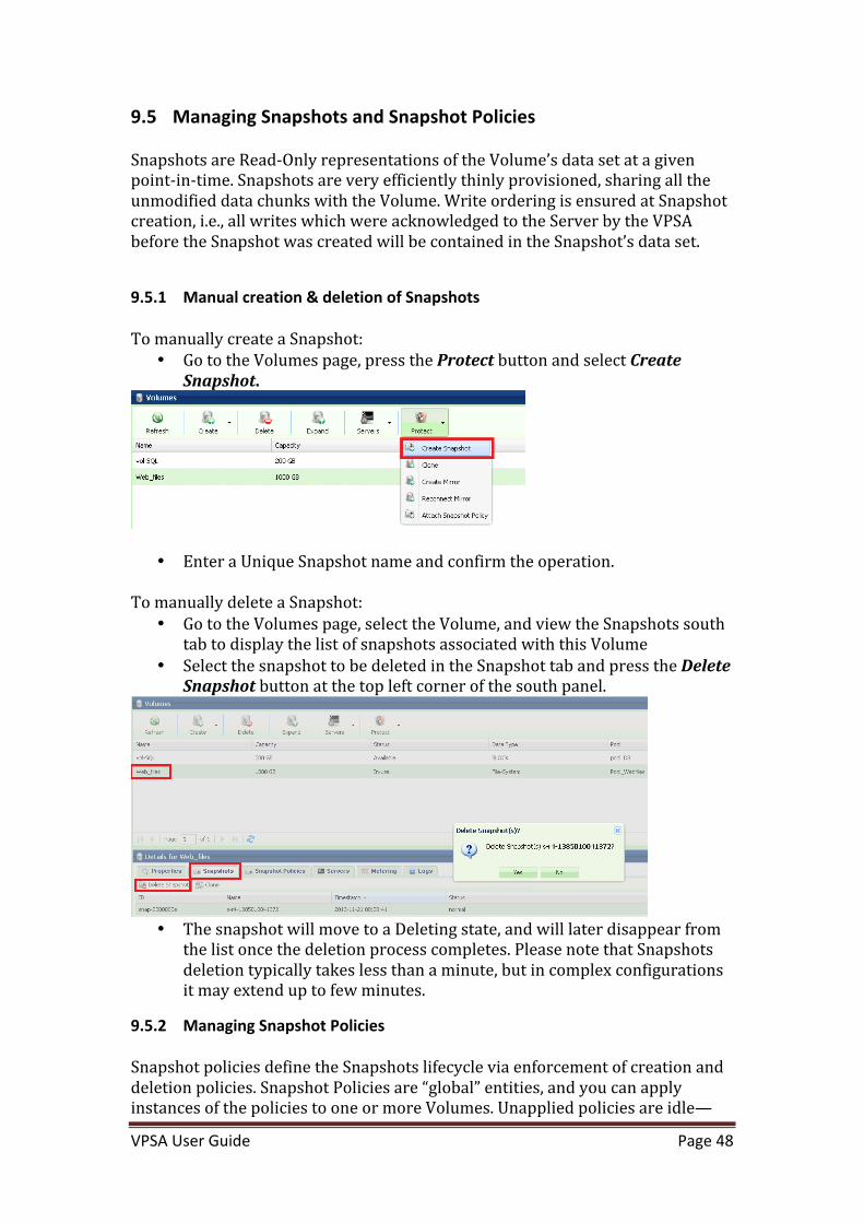
9.5.1 Manual creation & deletion of Snapshots To manually create a Snapshot:
• Go to the Volumes page, press the Protect button and select Create Snapshot.
• Enter a Unique Snapshot name and confirm the operation. To manually delete a Snapshot:
• Go to the Volumes page, select the Volume, and view the Snapshots south tab to display the list of snapshots associated with this Volume
• Select the snapshot to be deleted in the Snapshot tab and press the Delete Snapshot button at the top left corner of the south panel.
• The snapshot will move to a Deleting state, and will later disappear from
the list once the deletion process completes. Please note that Snapshots deletion typically takes less than a minute, but in complex configurations it may extend up to few minutes.
9.5.2 Managing Snapshot Policies Snapshot policies define the Snapshots lifecycle via enforcement of creation and deletion policies. Snapshot Policies are “global” entities, and you can apply instances of the policies to one or more Volumes. Unapplied policies are idle—

VPSA User Guide Page 49
they do not consume any resources and never create any snapshots. A few points to consider:
• You can apply a Snapshot policy to one or more Volumes. • You can apply multiple Snapshot Policies to a Volume. • If two or more snapshot policies are scheduled to create a Snapshot at the
same time on the same Volume, only a single snapshot will be created. That snapshot will be deleted only when all relevant delete polices approve its deletion.
• Snapshot creation time is a “rounded” time, regardless of the policy creation time. For example, if you created a Snapshot Policy at 9:02 which has a creation policy to create a snapshot every 10 minutes, the Snapshots will be created at 9:10, 9:20, 9:30 etc. (not at 9:12, 9:22, 9:32 etc.).
• You can decide whether empty snapshots are to be created or not. I.e. if the time has come to create a Snapshot according to the Creation Policy but no data has changed since the previous Snapshot, should a new and empty Snapshot be created.
• Few Snapshots Policies are predefined in the VPSA. To create a new Snapshot Policy:
• Go to the Snapshot Polices page and press the Create button. • Provide a meaningful name to the Policy. • Select the appropriate Creation Policy from the drop down list. • Define the number of Snapshots to retain in the deletion policy. • Allows Empty Snapshot Creation – Set this checkbox if you’d like
snapshots to be created according to the creation policy even if no data was modified since the previous snapshot.
• If you will be using this policy for Remote Mirroring, you can define a different number of Snapshots to retain on the DR site. This field is optional and defaults to the above deletion policy.
To Edit a Snapshot Policy
• Go to the Snapshot Polices page, select the Policy and press the Edit button.
• You can edit all of the Snapshot Policy’s attributes: Name, Creation Policy, Deletion Policy, and Allow Empty Snapshots rules.
• Note: You can modify a Snapshot Policy even when it is active on one or more Volumes. The modifications in the Policy’s behavior will be reflected on all relevant Volumes.

VPSA User Guide Page 50
• If you reduce the number of snapshots to retain for a Snapshot Policy that is active on one or mode Volumes, it will trigger the deletion of all snapshots that no longer meet the new Deletion Policy.
To Apply a Snapshot Policy on a Volume
• Go to the Volumes page, select the Volume and select Protect-‐>Attach Snapshot Policy from the menu.
• Select the Snapshot Policy to apply to the Volume, and press the Submit button.
To detach a Snapshot Policy from a Volume
• Go to the Volumes page, select the Volume, and press the Snapshot Policies south tab to view the Volume’s applied Snapshot Policies.
• Select the Snapshot Policy to delete, and press the Detach Policy button on the top left corner of the south panel.
• You will be prompted to decide whether or not to delete all the Volume’s Snapshots associated with this Policy.
Pause\Resume a Snapshot Policy You can pause an active Volume Snapshot Policy. New Snapshots will not be created. Existing Snapshots are not affected. Pausing a Snapshot Policy on one Volume has no impact on other Volumes that have this Policy active as well.

VPSA User Guide Page 51
• To pause a Snapshot Policy, go to the Volumes page, select the Volume, and press the Snapshot Policies tab on the south panel to view the Volume’s active Snapshot Policies.
• Select the Snapshot Policy and press the Pause Policy button on the top left corner of the south panel.
• The Policy will move to Paused status. • To resume a Policy: The Pause\Resume button toggles according to the
Policy status. Select a Policy in Paused state and press the Resume Policy button. The Policy Status will move to active.
Note: When the Enterprise Suite is disabled, all active Snapshot Policies are immediately paused, and when the Enterprise Suite is re-‐enabled, policies are resumed.
9.6 Cloning a Volume
Cloning a Volume is the process of creating a Read\Write zero-‐capacity replica of a Volume, with an identical data set as it exists in the Volume, in a selected point-‐in-‐time (which can be the time the Clone is created, or one of the existing Snapshots point-‐in-‐time). The result of the Cloning operation is a new Volume. The two Volumes now share all of the non-‐modified chunks. Only upon a first-‐write to a chunk, a Copy-‐On-‐Write occurs which allocates a new chunk and breaks the chunk sharing. You can create an unlimited number of Clones of a given Volume, either for the same data set (from the same Snapshot) or with different data sets. Clones are independent from each other, from the source Volume and from the Snapshots from which they were created. For example, you can delete the original Volume and\or Snapshot and leave the Cloned Volume unaffected. You can also modify Volume attributes of each Clone independently. You can only create clones within the Pool where the original Volume resides. To create a new Clone Go to The Volumes page, select the Volume to be cloned, and press the Protect-‐>Clone button.
• Enter the Cloned Volume name. • Select the point-‐in-‐time Snapshot which you wish to replicate its data set.
If you wish clone the current data set of the Volume, don’t select any Snapshot and,
• Submit the operation.

VPSA User Guide Page 52
• Alternatively, you can go to The Volumes page, select the Volume to be cloned, press the Snapshots tab at the south panel, select the desired point-‐in-‐time Snapshot, and press the Clone button at the top left corner of the south panel.
• Enter the new cloned Volume name.
The newly created Clone will appear as a regular Volume in the Volume list.
The Export name of a cloned Share will be identical to the Cloned Share display name.

VPSA User Guide Page 53
9.7 Managing Encrypted Volumes
Encryption management of Data-‐at-‐Rest (data on the Disk Drives) is done by the VPSA on a per-‐Volume basis, i.e., some Volumes can be encrypted while others cannot. A VPSA generates a random 128-‐bit unique Volume Encryption Key per encrypted Volume, and uses the Advanced Encryption Standard (AES) to encrypt and decrypt the Volume data. The Volume Encryption Keys are stored on disk as ciphertext, using AES with a 128-‐bit Master Encryption Key, which is generated from a user-‐supplied Master Encryption Password. The User owns the Master Encryption Password. It is never stored on any persistent media. Instead, only its SHA1 hash-‐sum is saved on disk for password validation. Since it is virtually impossible to restore the Master Encryption Password from the SHA1 hash-‐sum, you are fully responsible to retain and protect the Master Encryption Password. During VPSA operation, the Master Encryption Password itself is held in kernel memory of the VPSA. Core-‐dumping any User Mode process within the VPSA will not reveal the Master Encryption Key. The above method ensures that encrypted Data-‐at-‐Rest cannot be accessed without explicitly knowing the user-‐supplied Master Encryption Password, thus providing you full protection if you opt for Data-‐at-‐Rest Volumes encryption. Encryption attribute of Volumes cannot be changed! If you’d like to encrypt the data of a non-‐encrypted Volume or vice versa, you will need to create a new Volume and Copy the data. To create a Master Encryption Password, go to the Controllers page, and press the Encryption button. Read the instructions and warning. Type your Password and Submit the request.

VPSA User Guide Page 54
Store your Master Encryption Password in a secured place To create an Encrypted Volume, follow the steps in section 8.1 -‐ Creating and Deleting a Volume.
Encrypted Volumes are displayed with the icon.
9.8 Viewing Volume Properties
The Volumes Page displays the list of Volumes (Block and NAS) in the VPSA. Select a Volume and see its detailed information in the following south panel tabs:
Properties Each Volume includes the following properties:

VPSA User Guide Page 55
Property Description
ID An internally assigned unique ID.
Name User assigned name. Can be modified anytime.
Virtual Capacity Capacity of the Volume as seen by the attached Servers.
Available Capacity Free capacity of the NAS Share.
Mapped Capacity The used capacity (allocated from the Pool) of the Volume excluding its Snapshots and Clones
Data Copies Capacity
The used capacity (allocated from the Pool) of the Volume including its Snapshots and Clones
Status • Creating – Initializing Volume’s metadata. • Deleting – In process of deleting the Volume and
updating data chunks references. • Partial\Failed – The Volume is inaccessible due
to lower construct failure (on Pool or RAID Group level).
• Available – The Volume is healthy but is not attached to any Server.
• In-‐use – The Volume is healthy and is attached to one or more Servers.
Data Type • “Block” for Block Volume. • “File-‐system” for NAS Shares.
Pool The Pool name where this Volume is provisioned.
Server(s) Server Name attached to the Volume. Multiple(X) will be displayed when X servers are attached.
NFS Export Path The NFS Share export path to be used when mounting it.
SMB Export Path The SMB Share export path to be used when connecting to it from a Windows Server.
Access Type Access protocols which are used by the Servers which are attached to a NAS Share: NFS, SMB, or Multiple.
atime Update Yes\No – Indicates whether to update access time of NAS Share files and directories on every access, including read-‐access.

VPSA User Guide Page 56
SMB Only Yes\No – enable\disable locking optimizations
SMB Guest Access Yes\No – Allow\Block anonymous user access
Encrypted Yes\No
Extended Windows ACLs
Yes\No
Directory Creation Mask
Default directory umask value
File Creation Mask Default file umask value
Map archive Yes\No -‐ Maps the windows archive bit to the unix execute bit.
Optimized for serial small IO workload
Yes\No
Extended Metering Yes\No – Enabling extended metering
WWID SCSI unique World-‐wide ID. Use this value on Linux Servers to identify the Volume device when multipathing is configured.
Created Date & time when the Volume was created.
Modified Date & time when the Volume was last modified. Snapshots Lists the point-‐in-‐time Snapshots of this Volume. If you retain many Snapshots per Volume, you may want to use the Snapshot Filtering tool to find a specific Snapshot. For more details check here. Snapshot Policies
List of the Snapshot Policies which are attached to the selected Volume. The following Properties are provided per Snapshot Policy: Attribute Description
Name Display Name.

VPSA User Guide Page 57
Status Active or Paused.
Type The VPSA application controlling the Policy: • Snapshot Manager • Remote Mirroring
Create Policy Frequency of Snapshot creation.
Delete Policy Number of Snapshots to retain.
Dest. Delete Policy
Number of Snapshots to retain on Remote Mirror destination Volume.
For more details on Snapshot Policies management, check here. Servers Lists the Servers to which the Volume is attached. For block Volumes, the Lun Number associated with each Server is displayed. Metering The Metering Charts provide live metering of the IO workload associated with the selected Volume. The charts display the metering data as it was captured in the past 20 “Intervals.” An Interval length can be one of the following: 1 Second, 1 Minute, 10 Minutes, or 1 Hour. The Auto button lets you see continues updated live metering info (refreshed every 3 sec). The following charts are displayed: Chart Description
IOPs The Number of Read and Write SCSI commands issued to the selected Volume from all attached Servers.
Bandwidth (MB\s)
Total throughput (in MB) of Read and Write SCSI issued to the selected Volume from all attached Servers.
IO Time (ms) Average response time of all Read and Write SCSI issued to the selected Volume from all attached Servers.
Logs Displays all event logs associated with this Volume.
9.9 Filtering Snapshots
With VPSA you can create many snapshots on every Volume. Snapshots can be created manually, or by using Snapshot Policies, or by Remote Mirroring.
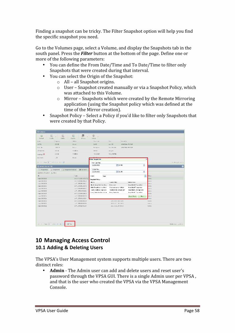
VPSA User Guide Page 58
Finding a snapshot can be tricky. The Filter Snapshot option will help you find the specific snapshot you need. Go to the Volumes page, select a Volume, and display the Snapshots tab in the south panel. Press the Filter button at the bottom of the page. Define one or more of the following parameters:
• You can define the From Date/Time and To Date/Time to filter only Snapshots that were created during that interval.
• You can select the Origin of the Snapshot: o All – all Snapshot origins. o User – Snapshot created manually or via a Snapshot Policy, which
was attached to this Volume. o Mirror – Snapshots which were created by the Remote Mirroring
application (using the Snapshot policy which was defined at the time of the Mirror creation).
• Snapshot Policy – Select a Policy if you’d like to filter only Snapshots that were created by that Policy.
10 Managing Access Control 10.1 Adding & Deleting Users
The VPSA’s User Management system supports multiple users. There are two distinct roles:
• Admin -‐ The Admin user can add and delete users and reset user’s password through the VPSA GUI. There is a single Admin user per VPSA , and that is the user who created the VPSA via the VPSA Management Console.
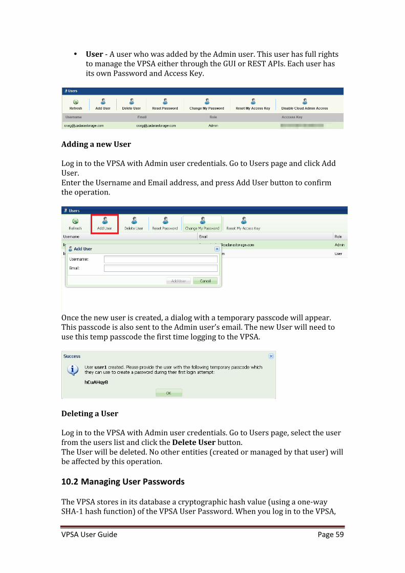
VPSA User Guide Page 59
• User -‐ A user who was added by the Admin user. This user has full rights to manage the VPSA either through the GUI or REST APIs. Each user has its own Password and Access Key.
Adding a new User Log in to the VPSA with Admin user credentials. Go to Users page and click Add User. Enter the Username and Email address, and press Add User button to confirm the operation.
Once the new user is created, a dialog with a temporary passcode will appear. This passcode is also sent to the Admin user’s email. The new User will need to use this temp passcode the first time logging to the VPSA.
Deleting a User Log in to the VPSA with Admin user credentials. Go to Users page, select the user from the users list and click the Delete User button. The User will be deleted. No other entities (created or managed by that user) will be affected by this operation.
10.2 Managing User Passwords
The VPSA stores in its database a cryptographic hash value (using a one-‐way SHA-‐1 hash function) of the VPSA User Password. When you log in to the VPSA,

VPSA User Guide Page 60
the entered password’s hash value is compared with the one stored in the database. Changing your password Log in to the VPSA, go to the Users page and click Change my Password button.
Enter your current password, a new password and confirm the new password. Click Change Password to submit the operation. Note: This operation is available to Admin User and to all regular Users. If you log as the Admin User and see the full list of the available VPSA Users, the Change my Password button will be enabled only when your Admin User is selected. Resetting User Password This operation is available only to the Admin User. You can reset any User’s password. A new temporary passcode will be created and sent to the Admin User email. The user will be requested to set a new password on next log in. Log in to the VPSA with Admin User credentials. Go to Users page, select a user from the users list and click Reset Password button Resetting API Key Zadara Storage employs a session-‐based authentication mechanism as a means to identify a user for every HTTP request to a VPSA. You initiate a session by logging in with the VPSA User Password. Upon successful authentication, a Secret API Token is sent back to the client application, for any subsequent REST API communication with the VPSA to identify the authenticated user and validate the session. At any time, you can generate a new Secret API Token, thus invalidating the previous token and any sessions using it. Go to the Users page, and press the Reset My Access Key button.

VPSA User Guide Page 61
Disable Cloud Admin Access
By default Zadara Storage Cloud Admins can access the VPSA to assist with troubleshooting and general support issues. You can disable this access by choosing “Disable Cloud Admin Access”.
10.3 Managing NAS Users Access Control
10.3.1 Creating NAS Users By default, "root" user and group, at the NFS client, are mapped to "root" user and group in the VPSA NFS server. All other client-‐side users are mapped to user "nobody" and group "nogroup." In order to set a basic NAS authentication so that users and groups at the client will be mapped to the corresponding users and groups at the VPSA NFS server, perform the following steps:
• Go to VPSA GUI > Controllers and press the NFS Domain button. The NFS Domain dialog will appear:

VPSA User Guide Page 62
• Enter NFS domain name identical to the domain name set in the Client and press the Update button. Typically, the default domain name on the Linux client side is "localdomain" and therefore this is also the default value in the VPSA.
NOTE1: In a Linux client, the domain name is usually set in the /etc/idmap.conf file. It is mandatory to have this value set. NOTE2: Make sure idmapd service is running (In Ubuntu idmapd service. In RedHat rpcidmapd) and that /sys/module/nfs/parameters/nfs4_disable_idmapping is set to “N” (to make it persistent set: GRUB_CMDLINE_LINUX_DEFAULT="nfs.nfs4_disable_idmapping=N” in /etc/default/grub and then run update-‐grub).
• Go to VPSA GUI >NAS Users, and press the Create button. a. Set the user name. b. Check NFS authentication. c. Select an NFS UID (in the range 1-‐999,999). d. If you wish to grant this user access to SMB shares as well, check
the SMB check-‐box and provide the User SMB Password (to be used later when mounting a share on a Windows Client).
10.3.2 Creating SMB Users • Go to VPSA GUI >NAS Users, and click the Create button. • Set the user name. • Check SMB authentication. • Provide the User SMB Password. You will be asked to provide this user
name and SMB password when mapping a network drive on the Windows Client
• If you wish to grant this user access to NFS shares as well, check the NFS check-‐box and select an NFS UID on the range of 1-‐999,999.

VPSA User Guide Page 63
10.3.3 Editing SMB Users Password It is possible to edit the password of an SMB User at any time. Go to NAS Users page and select Edit SMB Password:
• To change the SMB Password, enter a new SMB Password, confirm the
password and click the Change Password button • If the User is also defined with an NFS ID, you can select Remove
Password to erase the user SMB password.
10.4 Creating NAS Groups
You can create and view NAS Groups via the NAS Groups page. To create an NAS Group, go to the NAS Groups page and select Create:

VPSA User Guide Page 64
Enter a valid NAS Group Name. If you are creating a NFS group also add a valid NFS Group ID (on the range of 1-‐999,999) which matches the Group Name and ID on your Linux Server.
10.5 Enabling Active Directory Authentication
By joining the VPSA to the Active Directory (AD), users can use the same set of username and password that are stored in the AD to login the SMB shares.
10.5.1 Joining the VPSA to Active Directory To join the VPSA to a Microsoft Active Directory, Go to VPSA GUI > Domain Security, and click the Join button.
• In the opened dialog, fill out the following information:

VPSA User Guide Page 65
o Active Directory Server Name o Domain Name o Domain NetBIOS Name o Administrator Name (of the domain) o Administrator Password o Up to three DNS server IPs.
§ The IPs must be the same as the DNS server of your Active Directory, the three DNS entries are redundant to each other.
• Click the Submit button and confirm the following warning message requesting to ensure proper permissions of files and folders created on the VPSA shares prior to joining the AD:
NOTE: The joining of the VPSA to the active Directory may fail if the time on both the VPSA and the Active Directory Domain Controller is out of sync by more than a few minutes. Sync the time and try again. Different time zones are not an issue.
10.5.2 Changing Active Directory DNS You can update the DNS servers associated with your Active Directory without leaving the domain by selecting Change DNS
10.5.3 Leaving an Active Directory To leave the Active Directory, Go to VPSA GUI > Domain Security, and click the Leave button (Join & Leave are a toggled button).
Enter the Domain Administrator’s Name and Password and press submit.

VPSA User Guide Page 66
confirm the following warning message requesting to ensure proper permissions of files and folders created using AD, before leaving it:
11 Managing Remote Mirroring VPSA Asynchronous Remote Mirroring provides the ability to replicate your VPSA’s data asynchronously to a different pool in the same VPSA, a different VPSA, either locally, within the same Zadara Cloud, or remotely to a VPSA located in a remote region or even a different cloud provider. You can replicate a single source volume to any number of remote (or local) mirrors. Asynchronous Mirroring has minimal impact on IO throughout & response time from the Server perspective since the Server IO returns immediately after being written to the local VPSA storage (without waiting for acknowledge from the remote VPSA as it is required with Synchronous Mirroring). Later, the data is synchronized to the Remote VPSA “in the background.” The VPSA Remote Mirroring is Snapshot-‐based, meaning that only modified data chunks between two point-‐in-‐time Snapshots are synchronized. This has some major advantages:
• If a file\block was modified several times between two consecutive snapshots, only the last change will be synchronized, thus saving bandwidth.
• Snapshots are crash-‐consistent, thus at the Remote Site you always have crash-‐consistent point-‐in-‐time data set of your application.
• You can easily create many Read\Write Clones of your remote data at various point-‐in-‐time snapshots for Test & Dev.
The VPSA manages checkpoints to track the sync progress within a Volume\Snapshot. In case of a transport failure (line failure, VPSA failure etc), the VPSA has a clear checkpoint where to resume the sync. Remote VPSA communication is strongly authenticated and secured using cryptographic protocols that are designed to provide communication security over the Internet. Mirrored data is encrypted before being shipped to a remote VPSA in a different region. For efficient bandwidth utilization, Mirrored data is compressed before being shipped to the remote VPSA in different region.

VPSA User Guide Page 67
You can establish a many-‐to-‐many remote mirroring relationship for different Volumes between different VPSAs, i.e. a VPSA can mirror Volumes to many remote VPSAs and be at the same time the Destination VPSA for other Volumes in any other VPSA.
11.1 Creating a Local Mirror
To create a Local Mirror, go to the Mirroring page, and click the Create button.
On the next screen pick your local VPSA and the pool you want to replicate to. You cannot replicate to the same pool as the source volume is in.

VPSA User Guide Page 68
On the last screen pick the snapshot policies you want to replicate and click Submit.
11.2 Connect to a remote VPSA
The first step for building a DR plan is to establish a trusted relationship between your VPSAs.

VPSA User Guide Page 69
If the VPSAs are located in different Zadara Storage Clouds, you will need to first assign each VPSA a Public IP. See here for more details. Go to the Remote VPSAs page and click the Discover button.
Enter the following details:
• Remote VPSA IP Address: o If the remote VPSA is located in a different Zadara Storage Cloud
on a remote Region: § Enter the remote VPSA Public IP address. You can find it in
the VPSA details in the Management console or in the remote VPSA GUI, under Controllers-‐>Public IP.
§ Check the “Discover remote VPSA through Public IP” checkbox.
o If the other VPSA is located in the same Zadara Storage Cloud: § Enter the remote VPSA Management IP address. § Don’t check the “Discover remote VPSA through Public IP”
checkbox. • Username & Password – For authentication against the remote VPSA,
you are required to enter the username and password of a valid user in the remote VPSA. A cryptographic hash value (using a one-‐way SHA-‐1 hash function) of the entered password is sent to the remote VPSA.
11.3 Viewing remote VPSA Properties

VPSA User Guide Page 70
You can view all the remote VPSAs for which this VPSA has established a trusted relationship. For each VPSA the following details are provided:
• Remote ID – The VPSA ID of the remote VPSA. • Name – The name of the remote VPSA. • Provider – The name of the Cloud Provider where the remote VPSA is
located. • Software Version. • IP – Public or Management IP through which the VPSAs are connected. • Pool list – Each VPSA publishes the list of Pools that can be used to
provision the remote Volume. o Note: This list is not updated automatically. Click the Update
button to update the remote Pools info from the remote VPSA.
11.4 Creating a Remote Mirror
You can create the Remote Mirror from the Remote Mirroring page, by clicking Create. You will see a similar dialog:

VPSA User Guide Page 71
Name the mirror, remote volume name and select the source volume.
Choose the Destination VPSA, WAN Optimization v. I/O Performance Optimization (see below), and the destination pool. Click Next. WAN Optimization v. I/O Performance Optimization The VPSA supports selection between “I/O” and “WAN” data synchronization optimization. When “I/O” is selected, the VPSA synchronizes modified Pool
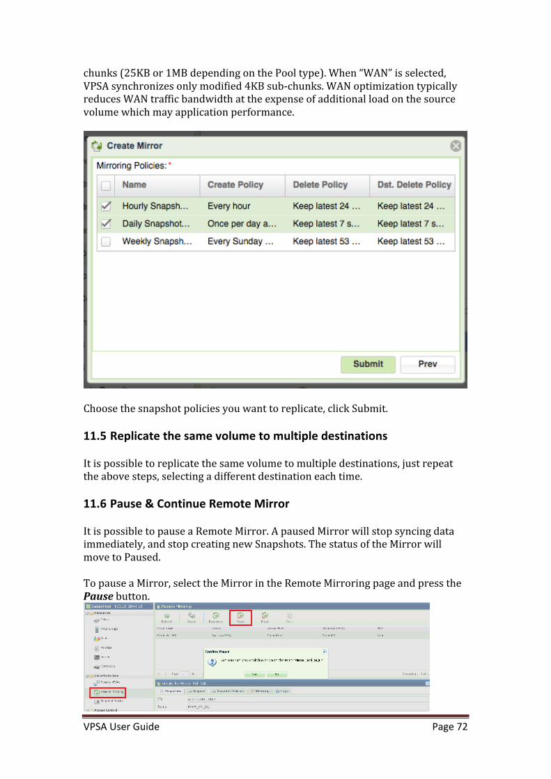
VPSA User Guide Page 72
chunks (25KB or 1MB depending on the Pool type). When “WAN” is selected, VPSA synchronizes only modified 4KB sub-‐chunks. WAN optimization typically reduces WAN traffic bandwidth at the expense of additional load on the source volume which may application performance.
Choose the snapshot policies you want to replicate, click Submit.
11.5 Replicate the same volume to multiple destinations
It is possible to replicate the same volume to multiple destinations, just repeat the above steps, selecting a different destination each time.
11.6 Pause & Continue Remote Mirror
It is possible to pause a Remote Mirror. A paused Mirror will stop syncing data immediately, and stop creating new Snapshots. The status of the Mirror will move to Paused. To pause a Mirror, select the Mirror in the Remote Mirroring page and press the Pause button.

VPSA User Guide Page 73
To Continue the Mirror operation, select the Mirror in the Remote Mirroring page and press the Continue button.
11.7 Managing Mirror Lifecycle
The Mirror controls the Remote Volume. It cannot be attached to any Server, nor can it be modified outside the scope of the Mirror. Hence it is treated as a special kind of “Dest Volume.” You can view Mirror destination Volumes on the “Dest Volumes” tab on the Pool Page, but they do not appear in the Volumes page.
11.7.1 Clone Destination Volume for Dev & Test of Remote Mirror For Dev & Test of the Remote Mirror, you can Clone the destination Volume using the data set of any Snapshot that was completely synced. You cannot create a Clone of the Snapshot that is currently being synced. The Cloned Volume is independent of the Destination Volume or the Mirror (i.e., you can delete both the Destination Volume and the Mirror and the Cloned Volume will not be affected). To Clone a Mirrored Destination Volume, go to the Remote Mirroring page on the Destination VPSA. Select a Mirror, and click the Clone button.

VPSA User Guide Page 74
• Select the point-‐in-‐time Snapshot which contains the data set that you wish to clone. The VPSA will assign a name to the Cloned Volume which is a concatenation of the Dest Mirror Volume name & the timestamp of the selected Snapshot. You can modify this name at any time.
• You can find the newly created Volume in the Volume Page:
11.7.2 Breaking a Mirror Breaking a Mirror is the process of deleting the Mirroring relationship between the Source Volume and the Destination Volume, while leaving sufficient information for future Mirror reconnect. The Destination Volume then becomes a “regular” Volume and the source and the destination Volumes are now independent. A mirror can be broken from the source or from the destination VPSAs. You can perform a future Mirror reconnect in both directions. To break a Mirror, go to the Remote Mirroring page, select a Mirror, and click the Break button. After confirming the operation, the Mirror Object in the Remote Mirroring page will disappear from the source and the destination VPSAs.
11.7.3 Reconnecting a Mirror As previously described, the VPSA “leaves” sufficient metadata on each Volume after it breaks a Mirror, for future possible Reconnect of the Mirror relationship. This metadata allows the VPSA to identify a remote Volume on a Remote VPSA, which used to have a Mirroring relationship anytime in the past, with a given Volume, and find the most recent Snapshot that is in-‐sync on both Volumes. This

VPSA User Guide Page 75
then enables it to reconnect the Mirror relationship and resume the sync process from the most updated data set. Mirror reconnect can be done in any direction, regardless of the previous Mirror direction. This provides the required flexibility for a DR plan. In case of a suspected source site disaster, you can break the Mirror, assign the Destination Volume to an application server, and work on the DR site. Once the source site is back, you can decide in which direction to resume the mirroring relationship. Note: When resuming Mirroring, the VPSA identifies the most recent point-‐in-‐time Snapshot that is completely in-‐sync on both source and destination Volumes. Any data that was written on the destination Volume after this snapshot will be deleted! To Reconnect a Mirror:
• Go to the Volumes Page, select the Volume you wish to act as the Source Volume of the Mirror, and click the Protect-‐>Reconnect Mirror button. Alternately, you can go to the Remote Mirroring Page and click Reconnect, and select the Source Volume.
• Select the Remote VPSA that contains a Volume that used to be a mirror pair of the selected Source Volume in the past.
• Press the Find Remote Volumes button. The VPSA will query the Remote VPSA and display suggested Remote Volumes which can be Destination Volumes of the Mirror, with the following info:
o Remote Volume name. o New Data – There is new data on the Remote Volume which was
written after the last sync point and which needs to be deleted to reconnect the Mirror.
o Last Sync – The timestamp of the most recent Snapshot. Any data written on the Source Volume after that timestamp will be synchronized to the remote Volume.
o Snaps to Del – Number of snapshots to delete on the Remote Volume. Please note that it is possible that empty Snaps need to be deleted while no new data is lost on the Remote Volume.

VPSA User Guide Page 76
• Press Continue. • Enter a name for the new Mirror. • Select Snapshot Policies for the new Mirror. • Press Submit to Reconnect the Mirror.
Note: Reconnect Mirror is blocked in the following cases:
• The Destination Volume is attached to a Server • The Destination Volume has active Snapshot Policies
11.8 Viewing Remote Mirror Properties
Remote Mirroring Page displays the list of Remote Mirrors that the VPSA participates in either as the Source or the Destination. Mirrors are not symmetric and hence the info displayed is slightly different between Mirrors, which the VPSA is the source of, and those that it is the destination of. Select a Mirror and check the detailed information in the following south panel tabs:

VPSA User Guide Page 77
Properties Each Remote Mirror includes the following properties: Property Description
ID An internally assigned unique ID.
Name User assigned name. Can be modified anytime.
Status • Idle – Mirror has nothing to Sync. • Failed • Paused • Syncing (X%) – Transferring the modified
data of the “Current Snapshot” to the remote Volume. X% stands for the syncing location inside the Snapshoot.
• Ready to sync/Syncing (X%) – Same as “Syncing” but at the destination VPSA.
Current Snapshot The most recently synced snapshot.
RPO Return Point Objective – This is the timestamp of the most recent fully synchronized Snapshot.
Optimization I/O Performance or WAN optimization
Created Date & time when the Mirror was created.
Modified Date & time when the Mirror was last modified.
Source VPSA\Provider The name of the Cloud Provider where the source VPSA resides.
Source VPSA\VPSA Source VPSA name.
Source VPSA\Pool Pool name where the Source Volume is provisioned. This parameter is available only at the source VPSA.
Source VPSA\Volume Source Mirror Volume name.
Destination VPSA\Provider
The name of the Cloud Provider where the destination VPSA resides.
Destination VPSA\ VPSA Destination VPSA name.
Destination VPSA\Provider
Pool name where the destination Volume is provisioned.
Destination VPSA\ Pool Destination Mirror Volume name.

VPSA User Guide Page 78
Snapshots Lists the point-‐in-‐time Snapshots of the Mirror on this VPSA. Please note that Mirror supports retaining different numbers of Snapshots on the source and the destination VPSAs. Each VPSA will display its own managed list. If you retain many Snapshots, you may want to use the Snapshot Filtering tool to find a specific Snapshot. For more details check here. Snapshot Policies List of active Snapshot Policies used by this Mirror to manage Snapshots on the source Volume and the destination Volume of the Mirror.
Source VPSA manages the Mirror Snapshots Policies; therefore modifications of the Mirror Snapshots Policies are allowed only on the Source VPSA. The source VPSA will update the Remote VPSA regarding any change in the Dest Delete Policy. You may make modifications while the Policy is active on a Mirror, and changes will be effective immediately. For example, if you change the policy to retain fewer snapshots, some older snapshots will be deleted immediately. The following info is provided per Snapshot Policy on the Source VPSA:
• Create Policy – Minimum time between Snapshots. • Delete Policy – How many snapshots to retain on Source Volume. • Dest Delete Policy – How many snapshots to retain on the Destination
Volume. The following info is provided per Snapshot Policy on the Destination VPSA:
• Create Policy – N\A. • Delete Policy – How many snapshots to retain on the Destination
Volume. This value is identical to the “Dest Delete Policy” on the Source VPSA.
• Dest Delete Policy – N\A. Metering The Mirror Metering Chart provides live info of the Mirror transfer throughput associated with the selected Remote Mirror. You can view the Mirror metering info on the source or the destination VPSA. The charts display the metering data as it was captured in the past 20 “Intervals.” An Interval length can be one of the following: 1 Second, 1 Minute, 10 Minutes, or 1 Hour. The Auto button lets you see continues updated live metering info (refreshed every 3 sec).

VPSA User Guide Page 79
Logs Displays all event logs associated with this Remote Mirror
12 Managing TechSupport Tickets You can manage your Zadara TechSupport tickets directly from your VPSA. Any support request is redirected to the Zadara Support portal at http://support.zadarastorage.com/home.
To Open a Support Ticket
• Go to the Tickets page and click Create. • Enter the Ticket Subject and description and press Submit. • A ticket will be created and a set of logs (ZSnap) will be uploaded to the
Zadara portal for analysis of the issue.
To Manage Support Tickets
• You can view the list of open support tickets, displaying the ticket number, date, status, and subject per ticket.
• You can Comment on a ticket or Add Zsnap to an existing ticket. • Finally, if you feel an issue is resolved, you can close it.