zeledyne versalux - hartung glass industries
TRANSCRIPT

Product Catalog

cover (left to right) :
1) Seneca Casino , VERSALUX®
BLUE, GREEN AND GREEN 2000;
architect: JCJ Architecture;
fabricator: Viracon; Glazier: CBO
Glass ; 2) Dudley Tower, Wausau,
Wisconsin; VERSALUX® BLUE
2000. fabricator: Custom Glass
Products of Schofield; Glazier:
Corcoran Glass; Wes Thompson
Photography 3) University of
Phoenix, VERSALUX® GREEN 2000R;
architects: Gromatzky Dupree
& Associates Southwest LLC,
Tucson, AZ; fabricator: Oldcastle
Glass, Phoenix, AZ; Glazier:
Glass Unlimited, Tucson, AZ.; Wes
Thompson Photography
Below: Las Olas Riverhouse, Fort
Lauderdale, FL, VERSALUX® BLUE
fabricator: Prelco; Glazier: Gamma;
Wes Thompson Photography
rich Heritage, new VisionZeledyne is a new company with a long and successful history. The original company began in 1919 when Henry Ford set up large-scale production facilities to manufacture glass for his Model T’s.
Today, Zeledyne is building upon that legacy. Headquartered in Allen Park, MI, with float and fabrication facilities in Tulsa, OK, Nashville, TN and Juarez, Mexico, we are committed to excellence in automotive and architectural glass quality and performance. Customers demanding product reliability and commitment to on-time delivery, at a fair market price, will recognize Zeledyne as a company uniquely positioned to meet these needs in the global market.
Independent and flexible, Zeledyne is able to quickly adapt to changing market demands while maintaining the highest standards of reliability and consistency. All Zeledyne manufacturing facilities are certified to ISO14001, the international environmental management standard, and to ISO9001, the international float glass quality standard. All Versalux products are manufactured with a minimum of 30% post-industrial recycled content. Although Zeledyne enjoys a rich history of dependable products, we won’t rest on our laurels. Our new vision is a promise to look toward the future….growing and changing to meet our customers’ needs, and providing them with the most reliable and innovative glass products and services in the world.
ZELEDYnE - ProDUctS WitH ViSion
Product Availability Chart 4Tinted Products 5Tinted Reflective Products 11Turtle Glass 16Technical Information 17Opacifying Options 26
index
a Greater Depth of colorWhether you’re a design professional, developer, fabricator or glazing contractor, you’ll be pleasantly surprised at how Versalux enhances the possibilities for your commercial or residential project.
Versalux is available in blue, green, grey and bronze providing a beautiful appearance and reducing glare. Compared to uncoated clear glass, tinted Versalux reduces heat gain and UV light transmission.
■ Versalux 2000 is offered in blue, green and grey, providing deeper richer tones and enhanced solar performance compared to Versalux.
■ Versalux R (formerly Versalux RC) is available in blue, green, grey and bronze. A reflective coating is applied to the Versalux tinted substrates to further enhance solar performance.
■ Versalux 2000R is produced when a pyrolytic reflective coating is applied to Versalux Blue 2000 and Green 2000 to block even more solar energy, including harmful ultraviolet rays.
■ Versalux 2000T provides a brighter blue or deeper green appearance by applying a titanium-based pyrolytic coating to Versalux Blue 2000 and Green 2000.
1
Where Vision meets Design
�
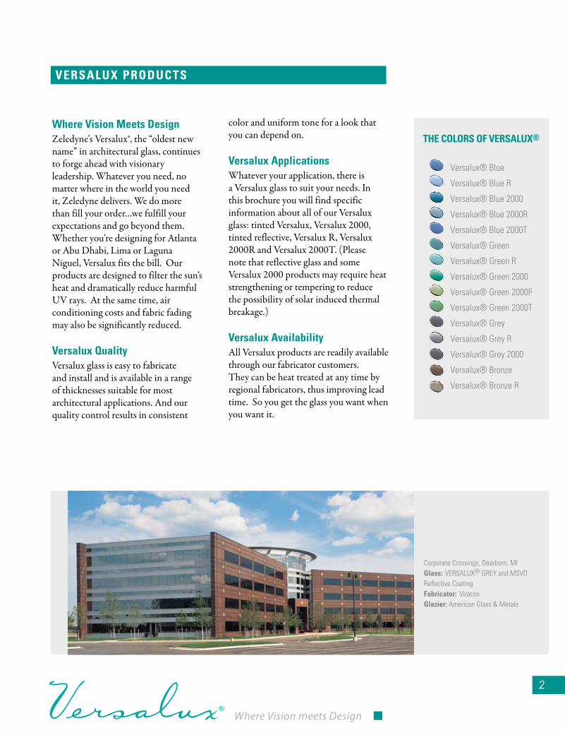
Where Vision Meets DesignZeledyne's Versalux®, the “oldest new name” in architectural glass, continues to forge ahead with visionary leadership. Whatever you need, no matter where in the world you need it, Zeledyne delivers. We do more than fill your order…we fulfill your expectations and go beyond them.Whether you’re designing for Atlanta or Abu Dhabi, Lima or Laguna Niguel, Versalux fits the bill. Our products are designed to filter the sun’s heat and dramatically reduce harmful UV rays. At the same time, air conditioning costs and fabric fading may also be significantly reduced.
Versalux QualityVersalux glass is easy to fabricate and install and is available in a range of thicknesses suitable for most architectural applications. And our quality control results in consistent
color and uniform tone for a look that you can depend on.
Versalux ApplicationsWhatever your application, there is a Versalux glass to suit your needs. In this brochure you will find specific information about all of our Versalux glass: tinted Versalux, Versalux 2000, tinted reflective, Versalux R, Versalux 2000R and Versalux 2000T. (Please note that reflective glass and some Versalux 2000 products may require heat strengthening or tempering to reduce the possibility of solar induced thermal breakage.)
Versalux Availability All Versalux products are readily available through our fabricator customers. They can be heat treated at any time by regional fabricators, thus improving lead time. So you get the glass you want when you want it.
VersAlux ProDucts
Versalux® Blue 2000R
Versalux® Blue 2000T
Versalux® Blue R
Versalux® Green R
Versalux® Grey R
Versalux® Bronze R
Versalux® Green 2000R
Versalux® Green 2000T
Versalux® Blue 2000
Versalux® Blue
Versalux® Green
Versalux® Grey
Versalux® Bronze
Versalux® Green 2000
Versalux® Grey 2000
the colors of VersAlux®
Corporate Crossings, Dearborn, MI Glass: VERSALUX® GREY and MSVD Reflective Coatingfabricator: ViraconGlazier: American Glass & Metals

�
for more information call 800-��1-�607 or go to zeledyne.com
Zeledyne’s Versalux color palette can dramatically improve and update most architectural retrofit and restoration projects. Our wide range of tinted and reflective tinted glass products can give aging buildings a new, inviting look.
With retrofit projects, there is frequently great latitude in glass selection. So you can creatively use colors and reflective coatings to achieve aesthetic goals while still conforming to mandates of the HVAC system.
Imagine the possibilities. Versalux products are available in hues of bronze, grey, green and blue along with a variety of visible light transmittances, shading coefficients and U-values in fabricated products to offer broad freedom in design. Moreover, Versalux products can be post heat treated, bent, laminated and fabricated into insulated glass.
Versalux products also reduce the transmission of harmful ultraviolet and near infrared rays while permitting variable amounts of daylight to enter through vision areas. In fact, when assembled in insulated units with clear or Low-E coated glass, many Versalux products are spectrally selective.*
On some retrofit projects, using Versalux products may actually lower heating and cooling costs and reduce HVAC capacity requirements.
Before After
Prizm Building, Tulsa, OKGlass: VERSALUX® BLUE 2000TGlazier: American Glass and Metal
retrofIt AND restorAtIoN
turn out-Dated Into up-to-Date
*Spectrally Selective Glazing Products have Visible Light Transmission of >40% and LSG ratio of >1.25 as outlined by the Federal Energy Management Program (DOE/EE-0173 Federal Technology Alert.)
DoWNloAD sPecs
You can download our specs at
www.zeledyne.com. Check out
our new website for an in-depth
view of Versalux products and
current technical specifications.
WWW.zeleDyNe.coM
Reglazing Process

Where Vision meets Design
�
All Versalux® products are manufactured in conformance with applicable provisions of ASTM C 1036 - 2001 (The American Society for Testing And Materials ASTM C 1036 - 2001 Standard Specification for Flat Glass.) Many Versalux products may be key components used by window fabricators when attaining “Energy Star” status for glazing assemblies.
ProDuct AVAIlABIlIty
THICKNESSES AVAILABLECOLOR1/4”, 5/16” (6, 8mm)
1/8”, 1/4”, 5/16” (3, 6, 8mm)
1/8”, 1/4” (3, 6mm)
1/4”, 5/16” (6, 8mm)
1/8”, 5/32“, 3/16”, 1/4” (3, 4, 5, 6mm)
1/8”, 5/32“, 3/16”, 1/4” (3, 4, 5, 6mm)
1/8”, 5/32”, 3/16“, 1/4” (3, 4, 5, 6mm)
Versalux® Blue 2000
Versalux® Blue
Versalux® Green
Versalux® Grey
Versalux® Bronze
Versalux® Green 2000
Versalux® Grey 2000
tinted Glass
THICKNESSES AVAILABLECOLOR
Versalux® Blue 2000R 1/4” (6mm)
1/4” (6mm)
1/4”, 5/16” (6, 8mm)
1/4” (6mm)
1/4” (6mm)
1/4” (6mm)
5/32”, 1/4” (4, 6mm)
5/32”, 3/16“, 1/4” (4, 5, 6mm)
Versalux® Blue 2000T
Versalux® Blue R
Versalux® Green R
Versalux® Grey R
Versalux® Bronze R
Versalux® Green 2000R
Versalux® Green 2000T
reflective Glass
Any of the above substrates may be available in additional thicknesses by special order. Check with your Zeledyne Regional Sales Manager for availability, minimum requirements and lead time.
Versalux products are available from qualified fabricators that fabricate sophisticated architectural glass products that comply with design professionals’ specifications. Available products are indicated above. Please contact your Zeledyne Regional Sales Manager or Architectural Support Manager for names of fabricators in your area.
Product Availability
115 East Crossroads Parkway, Bolingbrook, ILGlass: VERSALUX® BLUE 2000TDeveloper: IDIArchitect: Sparks Architects

Versalux blocks up to 80%¹ of the sun’s ultraviolet rays, substantially reduc-ing fading of most carpets, draperies, upholstery and artwork. It’s available in a wide variety of light transmittance levels and is designed to significantly reduce air conditioning costs for both residential and commercial applica-tions. With Zeledyne Versalux, you’ll help keep occupants cool while keeping expenses down.
The Versalux 2000 series is available in a range of thicknesses to accommodate most residential and architectural needs. It provides richer, deeper tones of blue, green and grey and is designed with improved solar-heat reduction properties for better performance than ever. And remember, all Versalux products give enhanced thermal performance when fabricated into insulated glass units. (See charts, pages 7-10.)
tINteD
looking Good outside, feeling Good Inside Versalux heat absorbing glass products not only enhance the exterior appearance of a building, they also raise interior energy efficiency while reducing solar glare. Versalux also substantially re-radiates the solar energy that it absorbs to the exterior and can reduce energy costs. And the soft, natural hues harmonize with today’s building materials giving a pleasing, contemporary look to both new and existing structures.
So with the combination of distinctive colors (two blues, two greens, two greys and bronze), plus excellent solar control properties and a wide range of visible light transmittances, it’s no wonder that Versalux colors have become a popular choice among the world’s leading architects and design professionals.
Specifying Zeledyne Versalux is obviously a decision you can feel good about. So call your regional sales manager or architectural support manager today. Visit our website at www.zeledyne.com for current contact information.
you can see the light Without taking the heat
North Scottsdale Corporate Center, Phoenix, AZGlass: VERSALUX® Blue R fabricator: Oldcastle-PhoenixGlazier: Romanoski Glass, Phoenix, Arizona
¹From LBNL WiNDOW 5.2 V5.2.17 COMPuTER ANALySiS. (300-380 nanometers.)

tinted MonolithicVersalux® Performance Characteristics - Monolithic Glass
It is recommended these products be heat treated (heat strengthened or fully tempered) to withstand solar induced thermal stresses. See Footnotes Page 26
Calculated by LBNL WINDOW 5.2 v5.2.17 COMPUTER PROGRAM
tINteD MoNolIthIc
News-Journal Center, Daytona Beach, FLGlass: VERSALUX® Blue 2000Architects: Baker Barrios Architects, Orlandofabricator: EFCO

@ Air Space Filling: Light Bands Air Filled – Dark Bands Argon Filled It is recommended these products be heat treated (heat strengthened or fully tempered) to withstand solar induced thermal stresses. See Footnotes Page 26
Versalux® Performance Characteristics - Tinted insulated Glass - inboard Lite Clear/Both Lites identical Thickness Except 5/16" (8mm) has 1/4" (6mm) interior Lite of Clear Float Glass.
7
tinted Insulated w/ clear
777
tINteD INsulAteD W/cleAr
Calculated by LBNL WINDOW 5.2 v5.2.17 COMPUTER PROGRAM

@ Air Space Filling: Light Bands Air Filled – Dark Bands Argon Filled It is recommended these products be heat treated (heat strengthened or fully tempered) to withstand solar induced thermal stresses.
See Footnotes Page 26
Versalux® Performance Characteristics - Tinted insulated Glass - Pyrolytic Low Emissivity Coated Clear Glass in identical Thickness of the Tinted Substrate (Except 5/16" (8mm) has 1/4" (6mm) Low E Coated Glass) Emissivity of Coated Surface is .156 - .158 & Total Solar Reflectance is 11% - 12%. Low Emissivity Coating on 3rd Glass Surface from Building Exterior.
88
tinted Insulated w/ Pyrolytic low-e
tINteD INsulAteD W/PyrolytIc loW-e
Calculated by LBNL WINDOW 5.2 v5.2.17 COMPUTER PROGRAM

@ Air Space Filling: Light Bands Air Filled – Dark Bands Argon FilledIt is recommended tinted glass products on this page be heat treated (heat strengthened or fully tempered) to withstand solar induced thermal stress.See Footnotes Page 26
Versalux® Performance Characteristics - Tinted insulated Glass - MSVD (Sputter) Low Emissivity Coated Clear Glass in identical Thickness of the Tinted Substrate (Except 5/16" (8mm) has 1/4" (6mm) Low E Coated Glass) Emissivity of Coated Surface is .043 & Total Solar Reflectance of 43%. Low Emissivity Coating on 3rd Glass Surface from Building Exterior.
�
for more information call 800-��1-�607 or go to zeledyne.com
��
tinted Insulated w/MsVD (sputter) low-e, third surface coating
�
tINteD INsulAteD W/MsVD (sPutter) loW-e, thIrD surfAce coAtING
Calculated by LBNL WINDOW 5.2 v5.2.17 COMPUTER PROGRAM
Where Vision meets Design
10
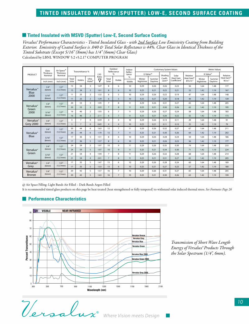
Versalux® Performance Characteristics - Tinted insulated Glass - with 2nd Surface Low Emissivity Coating from Building Exterior. Emissivity of Coated Surface is .040 & Total Solar Reflectance is 44%. Clear Glass in identical Thickness of the Tinted Substrate (Except 5/16" (8mm) has 1/4" (6mm) Clear Glass)
Transmission of Short Wave Length Energy of Versalux® Products Through the Solar Spectrum (1/4", 6mm).
10
tinted Insulated with MsVD (sputter) low-e, second surface coating
@ Air Space Filling: Light Bands Air Filled – Dark Bands Argon FilledIt is recommended tinted glass products on this page be heat treated (heat strengthened or fully tempered) to withstand solar induced thermal stress. See Footnotes Page 26
Performance characteristics
tINteD INsulAteD W/MsVD (sPutter) loW-e, secoND surfAce coAtING
Calculated by LBNL WINDOW 5.2 v5.2.17 COMPUTER PROGRAM

11
for more information call 800-��1-�607 or go to zeledyne.com
The outstanding UV and solar heat blocking capabilities of Versalux reflec-tive glass coatings make it an ideal choice for protection against over-exposure to sunlight. In fact, Versalux reflective glass can block over 93% of the sun’s damaging ultraviolet rays.¹ For even greater protection, choose Ver-salux 2000R, which blocks up to 97% of solar ultraviolet rays. You not only reduce air conditioning costs, but also guard against premature fading of fabrics and breakdown of plastic materials. Meanwhile, most plants and greenery flourish as vigorously as ever. For wide-range design flexibility, along with protection against solar heat and UV rays, Versalux reflective glass is the perfect choice in pyrolytically-coated glass.
Glass with flexibility Versalux reflective glass is also tops in versatility. Just like annealed, uncoated glass, it can be cut, drilled, laminated or made into insulated glass units with-out damaging the reflective surface. Versalux reflective glass can be heat-strengthened or tempered by regional fabricators. This flexibility can pay off with reduced lead times for both initial job requirements and replacement orders.
reflectIVe serIes
¹From LBNL WiNDOW 5.2 V5.2.17 COMPuTER ANALySiS. (300-380 nanometers.)
All Zeledyne reflective glass products, which include three blues, three greens, grey and bronze, are available in 1/4" (6mm) thickness. Additionally, special production thicknesses including 5/16" (8mm) are available in select colors. Your Zeledyne representative can fill you in on all the details. And to see how improved thermal performance is available with all Versalux reflective glass products when fabricated into insulated glass units, just see the charts on pages 13-15.
Glass with the right chemistry You’ll find that Versalux reflective glass products are compatible with most construction sealants. They are also compatible with the silicones, polysul-fides and urethanes commonly used in insulated glass manufacturing. Specific questions on compatibility should be directed to the sealant manufacturer. Versalux R & T products can be glazed with the reflective coating facing outdoors (1st surface) or indoors (2nd surface). As with all glass surfaces, the potential for problems caused by surrounding materials such as possible staining from weathering steel or concrete should be addressed prior to installation.
the Versalux reflective Glass Warranty All Versalux reflective glass products carry a 10-year coating limited warran-ty to the direct purchaser. To get a copy, just ask your Zeledyne representative.
Versalux reflective Glass — A clear reflection of your cost-saving skills
building photos hereAl Taawoun Towers - TIGERS Properties, Sharjah, UAEGlass: VERSALUX® BLUE 2000RAlum. contractor: TIGER Aluminium

reflective Monolithic
Versalux® Reflective Glass Performance Characteristics - Monolithic Glass
It is recommended these products be heat treated (heat strengthened or fully tempered) to withstand solar induced thermal stresses.
See Footnotes Page 26
reflectIVe MoNolIthIc
Phoenix on the Bay, Orange Beach, ALGlass: VERSALUX® GREEN 2000RArchitects: John M. Senkarik & AssociatesGlazier: Pensacola GlassEFCO WindowsWES THOMPSON PHOTOGRAPHY
Calculated by LBNL WINDOW 5.2 v5.2.17 COMPUTER PROGRAM

1�1�
reflective Insulated with clear
1�
Versalux® Performance Characteristics - Reflective insulated Glass: inboard Lite 1/4" (6mm) Clear Float Glass.
@ Air Space Filling: Light Bands Air Filled – Dark Bands Argon Filled
** May require heat treating to withstand solar induced thermal stresses when the reflective coating is glazed towards building interior. It is recommended these products be heat treated (heat strengthened or fully tempered) to withstand solar induced thermal stresses.
See Footnotes Page 26
1�
for more information call 800-��1-�607 or go to zeledyne.com
1�1�1�
reflectIVe INsulAteD WIth cleAr
Calculated by LBNL WINDOW 5.2 v5.2.17 COMPUTER PROGRAM

1�
reflective Insulated with Pyrolytic low-e
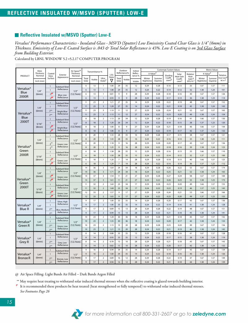
Versalux® Performance Characteristics - Reflective insulated Glass - Pyrolytic Low Emissivity Coated Clear Glass is 1/4" (6mm) in Thickness. Low Emissivity Coating on 3rd Glass Surface from Building Exterior. Emissivity of Low-E Coated Surface is .157 & Total Solar Reflectance is 11%.
@ Air Space Filling: Light Bands Air Filled – Dark Bands Argon Filled
** May require heat treating to withstand solar induced thermal stresses when the reflective coating is glazed towards building interior. It is recommended these products be heat treated (heat strengthened or fully tempered) to withstand solar induced thermal stresses.
See Footnotes Page 26
reflectIVe INsulAteD W/PyrolytIc loW-e
Calculated by LBNL WINDOW 5.2 v5.2.17 COMPUTER PROGRAM
Where Vision meets Design
1�
reflectIVe INsulAteD W/MsVD (sPutter) loW-e
1515
reflective Insulated w/MsVD (sputter) low-e
15
Versalux® Performance Characteristics - insulated Glass - MSVD (Sputter) Low Emissivity Coated Clear Glass is 1/4" (6mm) in Thickness. Emissivity of Low-E Coated Surface is .043 & Total Solar Reflectance is 43%. Low E Coating is on 3rd Glass Surface from Building Exterior.
@ Air Space Filling: Light Bands Air Filled – Dark Bands Argon Filled
** May require heat treating to withstand solar induced thermal stresses when the reflective coating is glazed towards building interior. It is recommended these products be heat treated (heat strengthened or fully tempered) to withstand solar induced thermal stresses.
See Footnotes Page 26
Calculated by LBNL WINDOW 5.2 v5.2.17 COMPUTER PROGRAM
15
for more information call 800-��1-�607 or go to zeledyne.com

turtle GlAss
16
florida Model lighting ordinance for Marine turtle Protection (“turtle Glass”)
* Complies with Florida Model Lighting Ordinance for Marine Turtle Protection (Florida Statutes, Section 161.163, Chp 62B-55.) ** May require heat treating to withstand solar induced thermal stresses when the reflective coating is glazed towards building interior. It is recommended these products be heat treated (heat strengthened or fully tempered) to withstand solar induced thermal stresses. See Footnotes on Page 26
Development along the Florida coast-line requires special consideration when designing and constructing a building – the safety of indigenous marine turtle hatchlings. It has been
discovered that light shining brightly from buildings within line of sight of the seashore attracts marine turtle hatchlings away from their natural environment at sea.
Due to the phenomena, the Florida Model Lighting Ordinance for Marine Turtle Protection requires architectural glass to transmit no more than 45% of the light from inside coastal buildings. Originally, Versalux® Blue 2000 was intended to transmit more than 45% of interior light, but research indicated that
a darker blue glass would not only better serve environmental needs, it would be more attrac-tive. The resulting Versalux® Blue 2000, by transmitting only 43% of light, complies with the coastal lighting code and has been specified for numer-ous Florida Atlantic Ocean and Gulf Coast buildings. Since the introduction of Versalux® Blue 2000, additional products have been developed by Zeledyne that comply with the ordinance as shown in the chart below.
Calculated by LBNL WINDOW 5.2 v5.2.17 COMPUTER PROGRAM
Where Vision meets Design
16

17
for more information call 800-��1-�607 or go to zeledyne.com
techNIcAl INforMAtIoN
Product AvailabilityAll Zeledyne Versalux® products are readily available and can be field fabricated by regional independent fabricators to reduce lead times and minimize construction delays.
As with any glass product manufactured with a coating, it is recommended that a mock-up be viewed by the design professional and building owner prior to final product selection. All Zeledyne Float Glass types meet manufacturing tolerances within applicable provisions of ASTM C 1036-2001 Standard Specification For Flat Glass.
It should be noted that all warranty statements disclaim any Zeledyne liability for breakage, replacement
costs, and incidental, special, or consequential damages.
tempering considerationsBlue, green, grey, and bronze tinted glass have heat-absorbing character-istics and retain heat as part of the absorption process. Zeledyne Versalux reflective glass, with the coating on the second surface of heat-absorbing glass, absorbs increased amounts of solar en-ergy and may require heat-strengthen-ing or tempering to reduce the possibil-ity of thermal breakage.
uniform load DataDesign professionals should review and adhere to all applicable national, state, and local building codes and regula-tions when selecting glass design load factors.
Glass supported on four sides(uniform load kPa)
3000
100
50
0
200150100500
2000
1000
50004000300020001000
1/4, 6.0mm60 Sec Duration Equivalent
Design Load (psf,kPa)Probability of Failure:
8 per 1000
Plat
e W
idth
(Inc
hes,
mm
)
Plate Length (Inches, mm)
43
2.52
1.51.25
1
.75
.5
(kPa) 80
6050
40
3025
20
15
10
(psf)
Glass supported on four sides (uniform Load kPa)
chart A
uniform load Data: Additional factors ■ Type of Exposure ■ Building Height ■ Orientation ■ Wind Gusting ■ Shape ■ Safety Glazing Requirements

uniform load/Glass strength tables Charts A and C may be used to deter-mine the adequacy of a glass substrate of the indicated thicknesses to with-stand a uniform static load for a 60 second duration. The wind load build-ings are exposed to is neither static nor uniform. It is the design professional’s responsibility to translate a project’s specified wind or design loads into uniform static loads of a 60 second duration equivalent.
four-side support Chart A may be used to determine maximum permissible annealed glass sizes at Indicated Design Loads expressed in Uniform Pounds Per Sq. Ft. for 1/4" (6.0mm) thick glass. This four-side support chart is based on glass supported on all four sides, a design factor of 2.5, and a probability of failure rate of 8 lites per 1,000.
Example: Glass Size: 65" x 90" • Locate the 90" line on the horizontal scale. • Determine the location of the 65" dimension between the 60" and 70" lines on the vertical scale. • Locate the intersection of a vertical line emanating from the 90" location on the horizontal scale and a horizon-tal line drawn from the location of 65" on the vertical scale. • Draw a line from the 0 point at the junction of the horizontal and vertical scales until it intersects the previously determined point (between the 20 lb. and the 25 lb. lines.) • Interpolate the point between the 20 lb. and 25 lb. lines. • Maximum load example lite of glass will withstand with probability of fail-ure rate of 8 lites per 1,000 is 22 PSF.
The dotted lines on the chart indicate points at which center of glass deflection will be 3/4" or greater. Strength of glass charts for additional thick-nesses of glass may be found in ASTM E 1300 - 94 Stan-dard Practice for Determin-ing the Maximum Thickness and Type of Glass to Resist a Specified Load. ASTM E 1300-94 is available from the American Society for Testing and Materials, 1916 Race St., Philadelphia, PA 19103.
four-side support Assuming annealed mono-lithic glass to have a factor of 1, the multiplying factors shown in Chart B may be used to determine the approximate uni-form load strength of further fabricated glass.*
Multiplying factors should not be used in combination, nor should they be used with the two-side support chart. Heat strengthened and fully tempered glass will withstand greater uniform loads than annealed glass. Deflection characteristics, however, are the same for identical thicknesses of annealed, heat strengthened, or annealed substrates.
National and local building codes and regulations for wind load and safety requirements set forth the minimums that must be met, but do not necessarily represent the most current product avail-ability for wind load factors.
GANA (Glass Association of North America) “Glazing Manual, 2004 edi-tion/ASCE Standard 7-95” and many other publications offer insight into the many facets constituting design load. 18
* All lites must be identical thickness of annealed lite.
techNIcAl INforMAtIoN
GlAss tyPe
Monolithic Fully Tempered 4.0
2.0
7.2
3.6
1.8
Insulated Glass (Both Lites Heat Strengthened)
Insulated Glass (Both Lites Annealed)
Monolithic Heat Strengthened
Insulated Glass (Both Lites Fully Tempered)
MultIPlyINGfActor
Center of glass deflection under specified loads must additionally be considered in selection proper glass thicknesses and types. Data for laminated glass products may be located in ASTM E 1300 - 94.
Multiplying Factor of Glass Types
chart B

1�
for more information call 800-��1-�607 or go to zeledyne.com
techNIcAl INforMAtIoN
two-side support Glazing that is framed or otherwise supported on only two opposite horizontal (sill and head) sides must be considered separately from four-side support-ed glazing in determin-ing the correct glass thickness to meet the specified uniform load. For this condition, glass strength is dependent only on the glass thick-ness and the length of the unsupported span. For two-sided support conditions, only mono-lithic annealed or tem-pered glass should be used. Using tempered
glass in lieu of annealed glass of the same thickness increases the allowable unsupported span by a factor of two.** The proper glass thickness to meet the desired uniform load for a given unsup-ported span can be selected by referring to the two-side support graph.
Glass deflection under wind loading is more pronounced with two-side sup-ported glass. A glass thickness that is sufficient to meet a given uniform load may exhibit deflection that is aestheti-cally unacceptable or psychologically bothersome to building occupants. Deflection can be reduced only by increasing the thickness for a given size lite of glass.
thermal stresses When glass is exposed to sunlight, solar energy is absorbed, causing the glass
temperature to rise. The rate at which glass temperature rises is dependent on the type and thickness of glass used. If the glass is not properly thermally isolated from the glass-framing system, or if it is glazed directly into a high heat capacity material such as concrete, the temperature of the glass edges may be significantly lower than that of the center portion of the glass.
Glass, like most materials, expands with increased temperature levels. The hotter center portion of the glass ex-pands more than the cooler glass edges, creating thermally-induced stresses at the glass edges. Thermal stresses are normally greatest at the center of each edge, diminishing toward the corners
Higher thermal stress may cause glass breakage unless proper cutting and glazing practices are followed. Proper design of the glazing system (reference Glazing Guidelines on Page 24) can reduce thermal and mechanical stresses. The ability of Versalux® products to re-sist breakage, due to both thermal and mechanical stresses, depends to a great degree on the edge strength of the glass. Clean-cut edges provide the greatest possible strength in glazed, tinted or reflective glass.
Under abnormal conditions where thermal stress increases breakage risk, resistance to thermal stress of a lite of glass can be increased by heat treating the substrate (heat strengthened or fully tempered). Heat treating also improves the glass product’s ability to withstand higher uniform loads (refer to uniform load data above). Although heat treating the glass increases its strength, it does not alter
** Applications using this factor must be closely evaluated to ensure anticipated center of glass deflection at the specified design load is limited to an acceptable degree.
GlAss suPPorteD oN tWo oPPosIte sIDes(uNIforM loAD kPa)
uNIforM loAD psiMAxIMuM uNsuPPorteD sPAN Vs. test Pressure
unsu
ppor
ted
span
– In
ches
unsu
ppor
ted
span
– M
eter
s
10 25 30 40 5015
0.6150
2.5
4.03.0
2.0
1.5
1.0
0.5
125
100908070605040
3025
20
15
10
0.8 1.0 1.5 2.0
3/4" (19 mm)5/8" (15 mm)1/2" (12 mm)3/8" (10 mm)
Glass Supported on Two Opposite Sides
chart c

Where Vision meets Design
�0
its deflection characteristics. Annealed, heat strengthened, and fully tempered substrates of the same thickness size will deflect under load at the same rate.
The thickness of a glass substrate may have to be increased for a given uniform load to limit center line deflection to an acceptable degree. Fully tempered glass, on occasion, can experience spontaneous breakage due to melting inclusions which can occur during the glass making process. Although the risk of spontaneous breakage is remote, architects and design professionals should consider other alternatives if glass fallout is a concern.
Interior heat trapsA heat trap on the interior surface of the glass exists when there is inad-equate air circulation to properly remove heat that can build up behind the glass. This condition can cause temperature differences within the lite of glass and subsequent thermal stresses that may not be acceptable with annealed glass. Spandrels: An example of a se-vere heat trap condition would be the spandrel area of a building. The space behind a lite of spandrel glass is blocked off to prevent airflow between floors. The temperature in this space will continue to rise when the spandrel glass is subjected to solar loading. It is for this reason that spandrel glass is tempered to increase the resistance of the glass to thermal breakage. Vision Areas: In vision areas, there is generally air movement across the inboard surface of the glass. If this air movement is restricted to a great
degree, a heat trap situation similar to that created in the spandrel area can occur. Suspended Ceiling Soffits: Suspended ceiling soffits must be positioned well to the room side to allow for natural convection. If the building design is such that natural convection cannot be provided, the head area should include vents that pro-vide a minimum of one square inch of ventila-tion for each inch of glass width, or the glass should be heat treated (Chart D). Interior Shading De-vices and Heat Outlets: The positioning of interior shading devices is a very important con-sideration in achieving adequate air movement across the inte-rior surface of the glass. Draperies, roller shades, or venetian blinds should be po-sitioned away from the glass to prevent restriction of airflow. A minimum clear-ance of 2" (50mm) should be provided between the inboard glass surface and the shading device. Also, a clearance must be provided between the shading device and the glass-framing members. A minimum clearance of 1-1/2" (38mm) should be provided at the top and bottom of the shading device to ensure adequate air movement. (Chart D)
If these clearances cannot be provided, in the case of venetian blinds, a lockout device should be used to limit the rotation of the blinds. This lockout device acts as a positive stop to prevent the blinds from being completely closed. For horizontal venetian blinds, the
VISION GLASS
2" (50MM)MINIMUM CLEARANCE
1-1/2" MINIMUM CLEARANCETOP & BOTTOM
POSITIVE VENTILATIONAT HEAD
SHADING DEVICEHEAT OUTLET
HEAT TRAP
techNIcAl INforMAtIoN
chArt DMinimum Clearance
�1
for more information call 800-��1-�607 or go to zeledyne.com
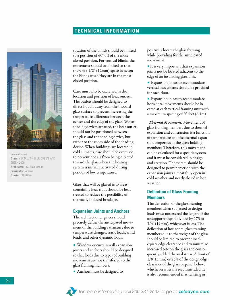
rotation of the blinds should be limited to a position of 60° off of the most closed position. For vertical blinds, the movement should be limited so that there is a 1/2" (12mm) space between the blinds when they are in the most closed position.
Care must also be exercised in the location and position of heat outlets. The outlets should be designed to direct hot air away from the inboard glass surface to prevent increasing the temperature difference between the center and the edge of the glass. When shading devices are used, the heat outlet should not be positioned between the glass and the shading device, but rather to the room side of the shading device. When buildings are located in cold climates, care should be exercised to prevent hot air from being directed toward the glass when the heating system is initially activated during periods of low temperature.
Glass that will be glazed into areas containing heat traps should be heat treated to reduce the possibility of thermally induced breakage.
expansion Joints and Anchors The architect or engineer should precisely define the anticipated move-ment of the building’s structure due to temperature changes, static loads, wind loads, and other dynamic loads.
■ Window or curtain wall expansion joints and anchors should be designed so that loads due to types of building movement are not transferred to the glass framing members.■ Anchors must be designed to
positively locate the glass framing while providing for the anticipated movement.■ It is very important that expansion joints not be located adjacent to the edge of an insulating glass unit.■ Expansion joints to accommodate vertical movements should be provided for each floor.■ Expansion joints to accommodate horizontal movements should be lo-cated at each vertical framing unit with a maximum spacing of 20 feet (6.1m).
Thermal Movement: Movement of glass framing members due to thermal expansion and contraction is a function of temperature and the thermal expan-sion properties of the glass-holding members. Therefore, this movement can be calculated for a specific system and it must be considered in design and erection. The system should be designed to permit erection with the expansion joints almost fully open in cold weather and nearly closed in hot weather.
Deflection of Glass framing Members The deflection of the glass framing members when subjected to design loads must not exceed the length of the unsupported span divided by 175 or 3/4" (19mm), whichever is less. The deflection of horizontal glass framing members due to the weight of the glass should be limited to prevent inad-equate edge clearance and to minimize increased bite on the glass and conse-quently added thermal stress. A limit of 1/8" (3mm) or 25% of the design edge clearance of the glass or panel below, whichever is less, is recommended. It is also recommended that twisting or
techNIcAl INforMAtIoN
Seneca CasinoGlass: VERSALUX® BLUE, GREEN, AND GREEN 2000Architects: JCJ Architecturefabricator: ViraconGlazier: CBO Glass

Where Vision meets Design
��
points, they can be moved so that the end closest to the vertical glass edge is within a distance equal to 1/8 the glass width or 6" (152mm), whichever is greater.
Each setting block should be sized to provide 0.1" of length per square foot (27mm per square meter) of glass area, but not less than 4" (102mm) of length.
The setting block should be 1/16" (1.6mm) less than full channel width or be positively located in the glazing channel to provide proper support for the entire glass thickness at all times. The height of the setting blocks should pro-vide the recommended nominal bite and minimum edge clearance for the glass.
When a lockstrip gasket glazing system is used, each setting block should be sized to provide 0.4" of length per square foot (109mm per square meter) of glass area, but not less than 4" (102mm) of length. The height of the setting block should be recommended by the lockstrip gasket manufacturer.
edge, face & Bite clearances The glazing system must provide adequate edge and face clearance to properly cushion the glass, to thermally and mechanically isolate the glass from the glass-framing members, and prevent glass-to-metal contact.
techNIcAl INforMAtIoN
chArt eDeflection of Glass Framing Members
QFC Tower, Doha, QatarGlass: VERSALUX® BLUE 2000TAluminum contractor: ALU NASA Aluminium
A-EDGE CLEARANCE
C-FACE CLEARANCE
B-BITE
CC
B
A
rotation of the horizontal members due to the dead weight of the glass be limited to 1" from the horizontal plane (Chart E).
Glass openings The glass framing system must both structurally support and adequately cushion the glass. To prevent mechani-cal and thermal stresses on the glass, the framing system should provide openings that are within specified tolerances for squareness, corner offset and bow. These tolerances are listed below: ■ Squareness - 1/8" (3mm) difference in the lengths of the diagonals. ■ Corner Offset - 1/32" (0.8mm) maximum offset at corners. ■ Bow - 1/16" (1.6mm) bow in a 4 ft. (1.22m) length of framing.
If variations from these tolerances are anticipated, details of the system should be submitted to a Zeledyne Glass representative for technical review. If job site conditions are found to ± outside these tolerances, correc-tions must be made before the open-ings are glazed.
setting Blocks Glass should be set on two identical setting blocks with a Shore A duro-meter hardness of 85+5.
The setting blocks should always be equidistant from the center line of the glass. The setting blocks prefer-ably should be centered at the bottom quarter points of the glass. When the wall design does not allow the setting blocks to be positioned at the quarter
−

��
for more information call 800-��1-�607 or go to zeledyne.com
The glazing system must also provide a nominal bite on the glass that will pro-vide adequate glass retention without excessive glass coverage. Excessive glass coverage can increase thermal stresses at the glass edge. Clearances and bite recommended for Zeledyne’s architec-tural glass products are shown in Chart F. (Note: Unshimmed glazing tapes should not be used.)
Glass spacersFace clearance for the glass should be provided by a continuous gasket or spacer of neoprene or an equivalent material. The use of intermittent shims should be discouraged. The Shore A durometer hardness of the continuous spacer will be determined by the practical requirements of the glazing system. In a wet-seal system, a low durometer material may be used to position the glass in the glazing channel and provide a backup for the sealant. In
a tape glazing system, a high durometer material may be used to apply adequate pressure to a preshimmed glazing tape.
edge BlocksGlass should be centered both verti-cally and horizontally in the opening. The glass must be free to “float” in the opening to prevent movement in the glass-framing members from being transmitted directly to the glass and creating mechanical stresses. For large lites or insulating glass units, edge blocks should be used to prevent lateral “walking” of the glass. This “walk-ing” occurs due to relative movement between the glass and the frame caused by the different thermal expansion and contraction characteristics of the materials. The edge blocks should be a minimum of 3" (76mm) in length. The blocks should be placed in the vertical channel width. They should be made of 55+5 Shore A durometer hardness neoprene and should be sized to pro-vide a nominal 1/8" (3mm) clearance between the block and the edge of the glass.
Weep systemsThe glazing system must be designed to prevent the accumulation of moisture in the glazing channel for prolonged periods. The weep system should in-corporate enough weep holes to ensure adequate drainage. When the weep sys-tem consists of weep holes at the sill in a location that can be wetted by driven rain, the holes should be equivalent to three 3/8" (9.5mm) diameter holes. One hole should be located at the center of the sill and one at each end between the jamb and setting block. When a lockstrip gasket system is used,
techNIcAl INforMAtIoN
GlAsstyPe
GlAssthIcKNess
INches
“A ”MINIMuM e DGe
cleArANce(INch)
“B”NoMINAl
BIte(INch)
“c”MINIMuM fAce
cleArANce(INch)
Monolithic
Insulating
3/32 2.5 1/8 1/4 1/16
1/8 3.0 1/8 1/4 1/8
5/32 4.0 3/16 5/16 1/8
3/16 5.0 3/16 5/16 1/8
1/4 6.0 1/4 3/8 1/8
3/8 10.0 5/16 7/16 3/16
1/2 12.0 3/8 7/16 1/4
1/4 6.0 1/4 3/8 3/16
1/2 12.0 1/8 1/2 1/8
5/8 15.0 1/8 1/2 1/8
3/4 19.0 1/4 1/2 3/16
1 25.0 1/4 1/2 3/16
Spandrel
MM
chArt fClearance and Bite Recommendations

Where Vision meets Design
��
an adequate weep system and auxiliary sealant around the entire periphery, or a combination of both, must be used.
Glass handling, cleaning & MaintenanceCare must be exercised in the handling and glazing of glass to prevent damage to the glass edge. The glass must not contact the glass framing member or the surrounding structure during the glazing operation. Glass edge damage can also occur when the glass is rotated or “pitched” on its corner on hard surfaces. For insulating glass units, it is recommended that a “rolling block” be used on the corner of the glass by the glazier when rotating the unit. The “rolling block” minimizes the possibil-ity of damaging the corner of the glass by distributing the weight of the unit along the edges rather than concentrat-ing the weight at the corner.
Versalux® glass products may be cleaned periodically using a soft, clean, grit-free cloth. To remove built-up grime and smudges, most commercial glass cleaning solutions work well. Both Versalux glass and coatings are very durable when proper cleaning techniques are employed. Glass sur-faces must be protected from scratches and should not be cleaned by mechan-ical buffers or any metallic scraper. Detailed cleaning instructions for Versalux products are available from Zeledyne upon request.
WatershedWhen a sealant filler is used over a gasket or glazing tape to provide a watershed, the sealant should not
extend more than 1/16" (1.6mm) above the metal sight line. This sealant filler increases the effective bite on the glass, which can increase thermal stress. Build-ing overhangs, surrounding structures, trees and shrubbery can create a variety of exterior shading patterns on glass in a building. This exterior shading can create varying degrees of thermal edge stress in the glass.The maximum thermal stress occurs when 25% or less of an individual glass lite is shaded and when the shaded area includes more than 25% of the lite’s perimeter. Generally, horizontal, vertical, and diagonal shading patterns are not as critical as shading that includes combina-tions of these shading patterns. Double diagonal shading that creates a pattern that is “V” shaped in nature with the center of the “V” located at the center of a glass edge is generally the most critical shading pattern.
Chart G shows some typical shading patterns that can be created in a build-ing. These are labeled “Acceptable,” “Marginal,” and “Harmful.” These draw-ings and designations can serve as a guide to the severity of thermal stress created by various exterior shading patterns. However, if an unusual shading pattern
techNIcAl INforMAtIoN
ACCEPTABLE SHADING MARGINAL SHADING HARMFUL SHADING
chArt GTypical Shading Patterns
Issa TowerGlass: VERSALUX® BLUE 2000Tconsultant: Emaret Al SharqAluminum contractor: Thomas BennetDistributor: Intraco UAE

is anticipated, it is recommended that a representative of Zeledyne be consulted in the design stages for technical review to determine if heat-strengthening or tempering is required.
other factors Heat treating for 3/16" (5mm) or heavier Zeledyne reflective glass or heat-absorbing glass should be considered to avoid breakage under the following con-ditions: glazing applications that induce mechanical stresses on the glass; designs requiring notches to be cut or holes to be drilled in the glass; painted signs or large labels used on the glass.
Glazing GuidelinesThe following glazing guidelines are intended to assist the design professional in developing glass support systems that will minimize the possibility of glass breakage due to thermal and mechanical stresses. In addition, specifiers and users can refer to the most current glazing recommendations published by GANA, AAMA, and IGMA.
As new and unique glazing systems are developed, variations from these guidelines may be justified. In such cases, precise details of the glazing system must be submitted to a Zeledyne representative for review.
The design of a properly functioning glazing system requires consideration of the following: the glass retaining system; the method of erection; the glass type and size; the various component and erection tolerances involved.
The glazing system must adequately support and cushion the glass to mini-mize loads on the glass due to building movements and movement occurring due to expansion and contraction of the glass-holding members.
techNIcAl INforMAtIoN
Silicon Oasis Headquarters, Dubai, UAEGlass: 6mm VERSALUX® BLUE 2000RAlum. contractor: ALICO
■ All Versalux tinted and tinted reflective products can be laminated to achieve greater sound attenuation properties.
■ Refer to GANA (Glass Association of North America) Laminating Division’s Laminated Glass Design Guide, latest edition, or contact architectural glass laminating fabricators for additional information.
sound control

cf = ceramic frit Sc = Water-Based Silicone coating Pf = Polyester film
Federal Technology alert DOE/EE-0173 Spectrally Selective glazings dated August 1998 states: Light to Solar Gain Ratio (LSG) is Visible Light Transmittance ÷ Solar Heat Gain Coefficient. (Spectrally Selective Glazing has a high Tv and low SHGC. The ratio of these parameters, or the light to solar gain ratio LSG=Tv/SHGC), is typically between 1.25 - 2.0". This FTA defines spectrally selective glazings as those that sharply cut off or reduce solar transmission beyond the visible range with a total solar transmission of no less than 0.40 in the visible range.)
@ Air Space Filling: Light Bands Air Filled – Dark Bands Argon Filled.
It is recommended these products be heat treated (heat strengthened or fully tempered) to withstand solar induced thermal stresses.
** These products may require heat treating to withstand solar induced thermal stresses when the reflective coating is glazed towards the building’s interior. (See pages 11-15).
a The Winter Nighttime U/R Values (K Values) are based on an outdoor temperature of 0°F (-17.8°C), an indoor temperature of 70°F (21°C), 15 mph (24km/h) outdoor air speed and no sun. The Summer Daytime U/R Values (K Value) are based on an outdoor temperature of 89°F (32°C), an indoor temperature of 75°F (24°C), a 7.5 mph (12km/h) outdoor air speed and a solar intensity of 248 BTU/Hr. per Ft2 (790 w/m2.)
b Shading Coefficient is the ratio of solar heat gain through a glass or glass and shading combination compared to that of unshaded 1/8" (3.0mm) clear float glass at normal incidence. The shading coefficient of 1/8" (3.0mm) clear float glass is 1.00.
c Solar Heat Gain Coefficient is the solar heat gain through glass relative to the incident solar radiation. SHGC is equal to approximately 86% of the shading coefficient.
d Relative Heat Gain is the combination of solar heat gain (transmitted and that amount of absorbed energy that is conducted or convected to the interior) and heat transfer due to the indoor/outdoor temperature differential. (Based on an ASHRAE solar heat gain factor of 200 BTU/Hr. per Ft2. (637 w/m2) and outdoor air 14°F (7.8°C) warmer than indoor air with no shading devices.)
e From LBNL WINDOW 5.2 V5.2.17 COMPUTER ANALySIS (300-380 nanometers.) Environmental conditions assumed: NFRC 100-2001 Summer and NFRC 100-2001 winter.
Performance data represents center of glass values calculated under the guidelines of LBNL WINDOW 5.2 V5.2.17 COMPUTER ANALySIS, assuming an air mass of 1.5.
Footnotes Apply to Tinted and Reflective Versalux® Monolithic, Insulated with Clear and Insulated with Low-E
* Edge deletion of silicone coating required, contact manufacturer for additional information.
GLASS SURFACE(When Viewed From Exterior)
SECOND (2)
CF, SC or PF CF, SC or PFCF or SCUncoated Surface
CF, SC or PF SCN/AReflective Coated Surface
Versalux Tinted Versalux R Versalux T
MONOLITHIC
GLASS SURFACE(When Viewed From Exterior)
SECOND (2)
THIRD (3)
FOURTH (4)
CF or SC*CF or SC*
CF or SC* CF or SC*
CF or SC*CF or SC*
CF or SC*
Uncoated Surface
Clear Glass
Clear Glass CF, SC or PF CF, SC or PFCF or SC
SC*N/AReflective Coated Surface
Versalux Tinted Versalux R Versalux T
INSULATED GLASS ( Inter ior L i te Clear)
E X T E R I O R L I T E
��
Popular opacifying options for 2nd, 3rd, or 4th Glass Surfaces of Spandrels
oPacifYinG oPtionS
26

Zeledyne 5555 South 129th East Ave., Tulsa, OK 74134P.O. Box 555, Tulsa, OK 74102 Telephone: (800) 331-2607 • FAX: (918) 254-5244
contact information
Ken Schraufnagle(313) 755-4352Fax: (313) [email protected]
Jeff Kaiser (262) 896-9103 Fax: (262) [email protected]
Bill Rooks(615) 350-5692Fax: (615) [email protected]
Craig Closser 303-840-4845 Fax: (918) [email protected]
Freda Sterling(480) 816-6672 Fax: (480) [email protected]
regional Sales managers
AK, AR, AZ, CA, CO, HI, IA, ID, KS MT, NM, NV, OK, MN, MO, NE, ND, SD, OR, TX, UT, WA, WY, Western Canada
Nord Petersen (817) 807-6028 Fax: (817) 244-9663 [email protected]
Margaret RussellAL, CT, DC, DE, FL, GA, IL, IN, KY, LA, MA, MD, ME, MI, MS, NC, NH, NJ, NY, OH, PA, RI, SC, TN, VA, VT, WI, WV, Eastern Canada
(770) 993-6978 TF (800) 838-1036 [email protected]
architectural Support managers
international Sales manager
(313) 755-4352 Fax: (313) 755-5986 [email protected] Schraufnagle
national Sales manager(313) 755-0621 Fax: (313) 755-5986 [email protected] Staffileno
order Entry and customer Service (800) 331-2607 • (918) 254-5202 • (918) 254-5203 • (918) 254-5204 FAX: (918) 254-5244EMAIL: [email protected]
The product specifications and descriptions used in this brochure were in effect at the time of publication. Zeledyne reserves the right to change product specifications without notice and without incurring obligation. See your Zeledyne Representative for the most up-to-date information on product availability and specification data.