zemel natphys plus supp 10
TRANSCRIPT

8/3/2019 Zemel NatPhys Plus Supp 10
http://slidepdf.com/reader/full/zemel-natphys-plus-supp-10 1/21
ARTICLESPUBLISHED ONLINE: 21 MARCH 2010 | DOI: 10.1038/NPHYS1613
Optimal matrix rigidity for stress-fibre
polarization in stem cellsA. Zemel1*†, F. Rehfeldt2,3*, A. E. X. Brown2, D. E. Discher4 and S. A. Safran5
The shape and differentiated state of many cell types are highly sensitive to the rigidity of the microenvironment. The physicalmechanisms involved, however, are unknown. Here, we present a theoretical model and experiments demonstrating that thealignment of stress fibres within stem cells is a non-monotonic function of matrix rigidity. We treat the cell as an active elasticinclusion in a surrounding matrix, allowing the actomyosin forces to polarize in response to elastic stresses developed in thecell. The theory correctly predicts the monotonic increase of the cellular forces with the matrix rigidity and the alignment of stress fibres parallel to the long axis of cells. We show that the anisotropy of this alignment depends non-monotonically onmatrix rigidity and demonstrate it experimentally by quantifying the orientational distribution of stress fibres in stem cells.These findings offer physical insight into the sensitivity of stem-cell differentiation to tissue elasticity and, more generally,introduce a cell-type-specific parameter for actomyosin polarizability.
Recent research has shown that the regulation of importantcellular processes, such as proliferation, differentiation andapoptosis, is controlled by the mechanical properties and
geometry of the cells and their environment1–11. Cell differentiationand other cellular processes have been shown to reach an optimumin a range of matrix rigidities that is characteristic of the nativetissue environment4–8; the rigidity of the environment can directthe shape and lineage specification of human mesenchymal stemcells7 (hMSCs). When plated on substrates with a rigidity thatmimics that of brain, muscle and bone, stem cells expresseddifferentiation markers corresponding to these tissue cells aftera few days and showed maximum expression on the respectivesubstrates. Significant differences in cell morphology, however,emerge within the first 24 h. The extent of cell elongation (aspect
ratio) depended non-monotonically on the rigidity of the matrix7
,adopting the characteristic polarized morphology of muscle cellsonly when placedon a matrixwith a rigidity that matched thetypicalstiffness of muscle tissue (E ≈ 10 kPa).
Here, we focus on the alignment of the contractile, actomyosinstress fibres in the cytoskeleton of adhering cells (Fig. 1) becausethey were shown to have an essential role in the active,mechanosensitivity of cells12, particularly in the determination of cell shape13 and differentiation14. We predict theoretically anddemonstrate experimentally that the matrix rigidity and the cellshape regulate the polarization of stress fibres in cells, and dictatethe preferential alignment of the stress fibres along the long axisof the cell15–17. We show that the alignment of stress fibres in stemcells depends non-monotonically on the matrix rigidity, attaining a
maximum value when thecell andmatrix rigidity aresimilar.We model the cell as an active, elastic inclusion in an infinite,homogeneous and isotropic medium and consider both two-dimensional (2D) and 3D geometries. The theory includes boththe passive forces arising from the elasticity of the cell andthe surrounding medium as well as the active forces generatedand regulated by the cells; this extends the treatment of passive
1Institute of Dental Sciences, Faculty of Dental Medicine, and the Fritz Haber Center for Molecular Dynamics, the Hebrew University-Hadassah Medical
Center, Jerusalem 91120, Israel, 2Department of Physics and Astronomy, University of Pennsylvania, Philadelphia, Pennsylvania 19104, USA, 3III.
Physikalisches Institut, Georg-August-Universität, 37077 Göttingen, Germany, 4Graduate Group of Physics and Astronomy, University of Pennsylvania,
Philadelphia, Pennsylvania 19104, USA, 5Department of Materials and Interfaces, Weizmann Institute of Science, Rehovot 76100, Israel. *These authors
contributed equally to this work. †e-mail: [email protected].
inclusions in solids to living matter. We show that a smallasymmetry in the early-time shape of an adhering cell (seeSupplementary Fig. S2) results in a symmetry breaking of theelastic stress in the cell that in turn, may direct the spontaneouspolarization of the stress-fibres in the cell. We invoke the use of an active cell polarizability that reflects the feedback between theelastic stresses in the cell and the active forces that the cell generatesto predict the anisotropic polarization of the forces in the cell anditsdependence on thecell shape andelastic characteristics.
Experiments were carried out to systematically analyse thealignment of stress fibres in hMSCs as a function of the cellshape and the rigidity of the environment. Cells were culturedon substrates of varying stiffness and sorted by their aspectratio. We show a quantitative analysis of stress-fibre polarization
in cells by staining for both actin and non-muscle myosin IIa(NMMIIa) and applying a segmentation algorithm to map theirspatial organization in the cell.
Our results suggest a generic mechanical coupling between thecell shape, the rigidity of the surroundings and the organizationof stress fibre in the cytoskeleton of stem cells. This identifiesa mechanical property of cells—stress-fibre polarization—that ismaximized at an optimal substrate rigidity, analogous to theoptimal rigidity found in stem-cell differentiation (for exam-ple, to muscle cells).
Theory of cell adhesion and actomyosin polarization
The anchoring of a cell to the extracellular matrix as well asthe active spreading of a cell on a surface involves a shape and
volume deformation that produces elastic stresses in the cell andthe matrix17–22. Nascent protein adhesion complexes (often termedfocal complexes12) that anchor the cell to the surrounding matrixgrow in response to these forces23 providing mechanical support forstronger, organized and more prominent actomyosinstress fibres inthe cell. The theory shows how the adhesion-induced stresses caninitiate a feedback that controls the amount and alignment of the
NATURE PHYSICS | ADVANCE ONLINE PUBLICATION | www.nature.com/naturephysics 1
8/3/2019 Zemel NatPhys Plus Supp 10
http://slidepdf.com/reader/full/zemel-natphys-plus-supp-10 2/21
ARTICLES NATURE PHYSICS DOI: 10.1038/NPHYS1613
χ
r = 1.67 3.30 2.30
S = 0.08 0.63 0.58
a b c
d e f
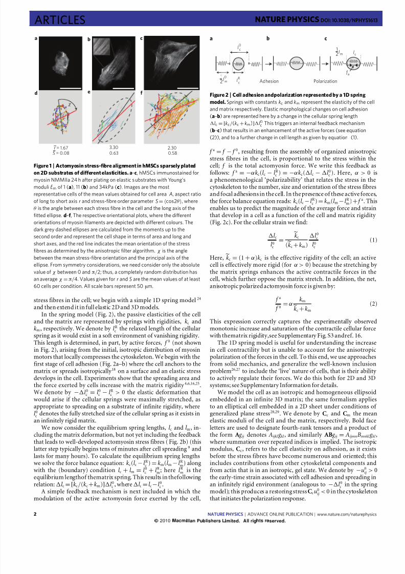
Figure 1 |Actomyosin stress-fibre alignment in hMSCs sparsely plated
on 2D substrates of different elasticities. a–c, hMSCs immunostained for
myosin NMMIIa 24 h after plating on elastic s ubstrates with Young’s
moduli E m of 1 (a), 11 (b) and 34kPa (c). Images are the most
representative cells of the mean values obtained for cell area A, aspect ratio
of long to short axis r and stress-fibre order parameter S= cos2θ, whereθ is the angle between each stress fibre in the cell and the long axis of the
fitted ellipse. d–f , The respective orientational plots, where the different
orientations of myosin filaments are depicted with different colours. The
dark grey dashed ellipses are calculated from the moments up to the
second order and represent the cell shape in terms of area and long and
short axes, and the red line indicates the mean orientation of the stress
fibres as determined by the anisotropic filter algorithm. χ is the angle
between the mean stress-fibre orientation and the principal axis of the
ellipse. From symmetry considerations, we need consider only the absolute
value of χ between 0 and π/2; thus, a completely random distribution has
an average χ =π/4. Values given for r and S are the mean values of at least
60 cells per condition. All scale bars represent 50 µm.
stress fibres in the cell; we begin with a simple 1D spring model24
and then extend it in full elastic 2D and 3D models.In the spring model (Fig. 2), the passive elasticities of the cell
and the matrix are represented by springs with rigidities, kc andkm, respectively. We denote by l Rc the relaxed length of the cellularspring as it would exist in a soft environment of vanishing rigidity.This length is determined, in part, by active forces, f 0 (not shownin Fig. 2), arising from the initial, isotropic distribution of myosinmotors that locally compresses the cytoskeleton. We begin with thefirst stage of cell adhesion (Fig. 2a–b) where the cell anchors to thematrix or spreads isotropically 18 on a surface and an elastic stressdevelops in the cell. Experiments show that the spreading area andthe force exerted by cells increase with the matrix rigidity 4,6,16,25.We denote by −l 0c = l 0c − l Rc > 0 the elastic deformation that
would arise if the cellular springs were maximally stretched, asappropriate to spreading on a substrate of infinite rigidity, wherel 0c denotes the fully stretched size of the cellular spring as it exists inan infinitely rigid matrix.
We now consider the equilibrium spring lengths, l c and l m, in-cluding the matrix deformation, but not yet including the feedbackthat leads to well-developed actomyosin stress fibres (Fig. 2b) (thislatter step typically begins tens of minutes after cell spreading9 andlasts for many hours). To calculate the equilibrium spring lengthswe solve the force balance equation: kc(l c − l Rc ) = km(l m − l Rm) alongwith the (boundary) condition l c + l m = l 0c + l Rm; here l Rm is theequilibrium lengthof thematrix spring. This results in thefollowingrelation: l c =[kc/(kc +km)]l 0c , where l c = l c −l 0c .
A simple feedback mechanism is next included in which themodulation of the active actomyosin force exerted by the cell,
Adhesion Polarization
l0
c
l0
m lR
c
f a
a b c
1
2
lm l
c
1
2
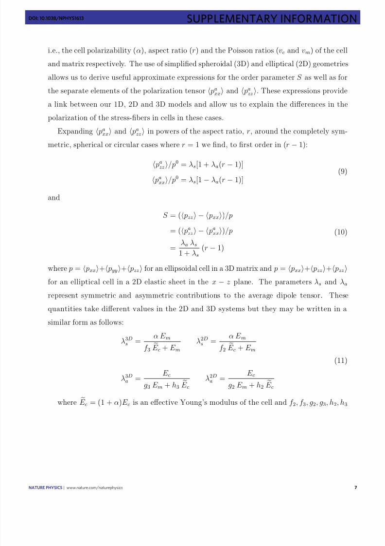
Figure 2 | Cell adhesion andpolarization represented by a 1D spring
model. Springs with constants kc and km represent the elasticity of the cell
and matrix respectively. Elastic morphological changes on cell adhesion
(a–b) are represented here by a change in the cellular spring length
lc = [kc/(kc +km)]l0c This triggers an internal feedback mechanism
(b–c) that results in an enhancement of the active forces (see equation
(2)), and to a further change in cell length as given by equation (1).
f a = f − f 0, resulting from the assembly of organized anisotropicstress fibres in the cell, is proportional to the stress within thecell; f is the total actomyosin force. We write this feedback asfollows: f a = −αkc(l c − l Rc ) = −αkc(l c − l 0c ). Here, α > 0 isa phenomenological ‘polarizability’ that relates the stress in thecytoskeleton to the number, size and orientation of the stress fibresand focal adhesions in the cell. In the presence of these active forces,
the force balance equation reads: kc(l c − l Rc ) = km(l m − l Rm)+ f a. Thisenables us to predict the magnitude of the average force and strainthat develop in a cell as a function of the cell and matrix rigidity (Fig. 2c). For the cellular strain we find:
l c
l 0c=
kc
(kc +km)
l 0cl 0c
(1)
Here, kc = (1 + α)kc is the effective rigidity of the cell; an activecell is effectively more rigid (for α > 0) because the stretching by the matrix springs enhances the active contractile forces in thecell, which further oppose the matrix stretch. In addition, the net,anisotropic polarized actomyosin force is given by:
f a
f 0= α kmkc +km
(2)
This expression correctly captures the experimentally observedmonotonic increase and saturation of the contractile cellular forcewith thematrix rigidity,see Supplementary Fig. S3 andref. 16.
The 1D spring model is useful for understanding the increasein cell contractility but is unable to account for the anisotropicpolarization of the forces in the cell. To this end, we use approachesfrom solid mechanics, and generalize the well-known inclusionproblem26,27 to include the ‘live’ nature of cells, that is their ability to actively regulate their forces. We do this both for 2D and 3Dsystems; see Supplementary Information for details.
We model the cell as an isotropic and homogeneous ellipsoid
embedded in an infinite 3D matrix; the same formalism appliesto an elliptical cell embedded in a 2D sheet under conditions of generalized plane stress28,29. We denote by Cc and Cm the meanelastic moduli of the cell and the matrix, respectively. Bold faceletters are used to designate fourth-rank tensors and a product of the form A g ij denotes Aijkl g kl , and similarly AB g ij = AijmnBmnkl g kl ,where summation over repeated indices is implied. The isotropicmodulus, Cc, refers to the cell elasticity on adhesion, as it existsbefore the stress fibres have become numerous and oriented; thisincludes contributions from other cytoskeletal components andfrom actin that is in an isotropic, gel state. We denote by −u0
ij > 0the early-time strain associated with cell adhesion and spreading inan infinitely rigid environment (analogous to −l 0c in the springmodel); this produces a restoring stress Ccu0
ij < 0 in the cytoskeletonthat initiates the polarization response.
2 NATURE PHYSICS | ADVANCE ONLINE PUBLICATION | www.nature.com/naturephysics

8/3/2019 Zemel NatPhys Plus Supp 10
http://slidepdf.com/reader/full/zemel-natphys-plus-supp-10 3/21
NATURE PHYSICS DOI: 10.1038/NPHYS1613 ARTICLES
The active actomyosin forces in the cytoskeleton are modelledby a local distribution of ‘force dipoles’30–32 that arise from theequal and opposite forces exerted by myosin motors at two nearby pointson actin filaments. These arerepresentedby a tensorquantity pij, which is the average (active) dipole density per unit volume.We assume that these force dipoles polarize in response to thelocal stress in the cell, changing their magnitude and orientationfrom their average, isotropic initial value p0
ij. We denote by
pa
ij
= pij
− p0
ij
, the anisotropic polarization tensor of the force
dipoles in the cytoskeleton and in analogy to the spring model, weassume a feedback response of the form:
paij = −αCc(uc
ij −u0ij ) (3)
where α denotes the active cellular polarizability (see Supplemen-tary Information) and Cc(uc
ij −u0ij ) is the mean stress developed in
the cell26. The strain and the forces that develop in the cell becauseof this feedback response are given by the self-consistent solution of the elastic equations along with the feedback effect of equation ( 3).This predicts that thestrain andthe cell force aregiven by:
ucij =[
A(Sm −I)+I]u0
ij (4)
and
paij = −αCc
A(Sm −I)u0ij (5)
withA = [I+Sm(Cc −Cm)C−1m ]−1; I is the unit tensor. The quantity Cc = (I+α)Cc is the effective elastic modulus of the cell (analogous
tok in the spring model). This tensor embodies the ‘live’ propertiesof cells through the cell polarizability, α. The tensor, Sm, is theEshelby tensor26,27, a function of the cell shape and the Poisson ratioof thematrix. Equations (4) and(5) (which generalizeequations (1)and (2) of the spring model) allow us to explore the relationshipbetween the cell shape and the polarization of the forces, and topredict how anisotropic stress fibres first arise. The establishmentof cell shape and polarization of stress fibres occur on a timescale of hours to days, during which the elastic properties of cytoskeleton
and cell shape vary. However, the final steady state of the cellemerges from an early-time breaking of symmetry, the origin andmechanical consequencesof which aredescribed by ourmodel.
Predictions and experimental observations
Experimentally, focal adhesions and stress fibres have been shownto grow and develop parallel to the direction of an appliedforce33, consistent with the more general observation that cellstend to polarize in the direction of stronger elastic resistance34.We thus consider the simplest model in which a cell respondsto stresses by locally modulating its active actomyosin forcesonly in directions parallel to the local stress. In this case, theisotropic fourth-rank tensor, α, can be replaced by a single positivescalar quantity, α, and pa
ij = −αCcucij (see equation (3)). In the
Supplementary Information we discuss an alternative form forα
,but the conclusions of the main body of the article are unalteredin that model as well.
To illustrate how the shape of the cell alone can be responsiblefor the polarization anisotropy, we assume, for simplicity, andin line with experiments18 that the initial-time adhesion-inducedstress, Ccu0
ij , is isotropic, includingthe contributionarising from theearly-time force dipoles, p0
xx = p0 yy = p0
zz = p0. Nevertheless,the global shape change (elongation of the cell) that accompaniesthe polarization of stress fibres in the cell may involve furtheraxial stretching of the cytoskeleton. This effect is considered below,but we first focus on the consequences of the isotropic forcesexerted by the cell. Although the actual proportion of isotropicdipolar forces, p0
ij, in the total stress exerted by the cell, Ccu0ij ,
is unknown, for simplicity, and without loss of generality we use
0.1
0.2
0.5
2
5
r = 10r = 10
5
2
1
2z x
¬0.1
0
0.1
E m /E c
E m /E c
0
0.1
0.2
0.3
0.4
0.5
0.01 1 1000
3
⟨ p
a i i ⟩ / p 0
¬0.2
0.2
O r d e r p a r a m e t e r
⟨ p
a z z
¬ p
a x x
⟩ / p
O r d e r p a r a m e t e r
⟨ p
a z z
¬ p
a x x
⟩ / p
0.01 1 100
E m /E c
E m /E c
0.01 1 100
0.01 1 100
1
2
⟨ p
a i i ⟩ / p 0
0
3a b
c d
Figure 3 | Cell polarization as a function of the ratio of Young’s modulus
of thematrix, E m, and the cell, E c, inboth our 2Dand 3Dmodels. The
plots are shown for different values of the cellular aspect ratio, r. a,b, The
normalized average dipole elements pazz (solid lines) and pa
xx (dashed
lines) corresponding to the forces in the directions that are respectivelyparallel (z) and perpendicular (ˆ x) to the long axis of the cell (dark grey:
r= 5, light grey: r= 2) for our 3D (a) and 2D (b) models. c,d, The
calculated orientational order parameter of the stress fibres that is given by
the normalized difference (pazz−pa
xx)/p for our 3D (c) and 2D (d)
models. The colour coding indicates the aspect ratio. In this plot, the
Poisson ratio of the matrix and the cellular domain are taken to be
νm = 0.45 and νc = 0.3 and the magnitude of the polarizability is α = 3.
Ccu0ij = p0
ij in the calculations presented below. We model cellsin 3D as spheroids with long-axis (taken to be in the z direction)length c and short-axis (taken to be in the x – y plane) radius a.Similarly, in our 2D model the cell is modelled by an ellipse withlong and short axes c and a respectively; in both cases r = c /a is the
aspect ratio of the cell.Figure 3 shows our results for both the 2D and 3D systems.Figure 3a,b shows the normalized dipole elements pa
zz / p0 and pa
xx / p0, as a functionof the ratio of Young’smodulus of the matrixand the cell, Em/Ec, for two values of the aspect ratio r . Consistentwith experiment16, our 1D spring model and our estimate of thetotal myosin content in the stress fibres (Supplementary Fig. S3),we find that the magnitude of the cellular forces in both the x and z directions increases monotonically with the rigidity of thematrix up to the same saturation value, pa
zz / p0 = pa xx / p0 = α. For
intermediate values of the matrix rigidity, the matrix tractions thatoppose the cellular forces turn out to be stronger along the longaxis of the cell. This fact, which is entirely due to the anisotropicshape of the cell, is responsible for the stronger polarization of the
forces along the long axis of thecell. Thus, for rod-like cells orientedparallel to the z axis, we find that pazz > pa
xx . The preferentialalignment of stress fibres (as well as of the sarcomeres in musclecells) parallel to the long axis of cells is a common experimentalobservation15–17, which hasnot been explainedtheoretically.
Our theory shows that the polarization of the stress fibresin the cell should depend non-monotonically on the matrixrigidity. To illustrate this behaviour, Fig. 3c,d plots the normalizeddifference, S = ( pzz − pzz )/ p = ( pa
zz − pa xx )/ p, which can be
shown to be equal to the orientational order parameter of thedipoles; here p is the trace of the mean dipole tensor, pij. Inboth 2D and 3D we find the same, generic, Lorentzian type(that is, a Lorentzian multiplied by the linear factor Em/Ec) of functional dependence for S as a function of Young’s moduli ratio:S=
a(Em/Ec)/[b((Em
−E0)/Ec)2
+1], where a,b,E0 are complicated
NATURE PHYSICS | ADVANCE ONLINE PUBLICATION | www.nature.com/naturephysics 3

8/3/2019 Zemel NatPhys Plus Supp 10
http://slidepdf.com/reader/full/zemel-natphys-plus-supp-10 4/21
ARTICLES NATURE PHYSICS DOI: 10.1038/NPHYS1613
functions of the aspect ratio, cell polarizability, Poisson ratio of thecell and matrix and dimensionality of the system.
We find that the polarization of the forces in the cell ismaximal at an optimal ratio of the matrix and cell rigidities,(Em/Ec). The explanation for this important feature is as follows.Consider the two extreme limits of a cell in an infinitely rigidand infinitely soft matrix. In the former case, because the matrixexerts strong tractions that completely oppose the initial, isotropic,inward pulling forces of the cell, f 0
i
=Ccu0
ij n j , the early-time
(tensile) stressthat develops, Cc(uc ,0ij −u0ij )=−Ccu0
ij , is also isotropic(see Supplementary Equation (6)); this results in an isotropicpolarization of the stress fibres because pa
ij = σ cij /α (whereσ cij = Cc(uc
ij −u0ij )). In the opposite limit of an infinitely soft matrix,
the matrix resistance, and consequently the cellular stress, drops tozero in all directions, thus providing no orientational cue for thepolarization of stress fibres in the cell. Between these two limits,the forces in different directions increase with different rates withthe matrix rigidity as seen in Fig. 3a,b. As the saturation values areindependent of direction, the difference in the polarization, paralleland perpendicular to the long axis of the cell, has a maximum at acertain value of the matrix rigidity.
Interestingly, we predict that the optimal ratio, (Em/Ec), scalesas
∼
√ 1
+α (see Supplementary Information). As α is, in general a
cell-type-specific parameter, this scaling suggests that different celltypes would possess a different level of sensitivity to the anisotropy of the stress in the cell. In addition, our theory shows that thestress-fibre polarization in 2D is larger by a factor of ≈2 comparedwith 3D. In 3D the cell is surrounded by a matrix that morestrongly suppresses the anisotropy of the elastic stress in the cell.In the Supplementary Information we present a more quantitativeanalysis of these arguments.
Thus far we considered the sole effect of the stress anisotropy that results from the cell shape. This gives rise to a non-monotonicdependence of stress-fibre polarization on the matrix rigidity.The stress-fibre polarization however is often accompanied by asimultaneous narrowing and elongation of the cell; see Fig. 1. Tomodel the consequences of the stress associated with cell elongation
we include an axial contribution to the early-time elastic stress Ccu0
ijexerted by thecell andcalculateits effecton thepolarization of stressfibres in the cell. We note that this is an approximation becausethe cell shape changes continuously but nevertheless it capturesan important elastic consequence of cell spreading anisotropy. Wethus write Ccu0
ij = p0(δij +ηδiz δ jz ), where the second term is an axialstress along the z axis—the direction of cell elongation. Like theseparate elements of the stress tensor σ c xx and σ czz in the previouscase, the stress resulting from this axial contribution increases withthe matrix rigidity. Figure 4a shows the predicted effect of this axialstress on the polarization of the stress fibres in the cell. Ratherthan dropping to zero as the matrix rigidity increases, the orderparameter saturates to a finite value given by ηα/(ηα + d + dα),where d = 2,3 is the dimensionality.
To test the predictions of our model we imaged actin andNMMIIa in hMSCs sparsely grown on substrates of differentelasticities (Fig. 1a–c). The overall aspect ratio r of the cell and theorientation of the contractile stress fibres have been determined;to quantify the polarization response we calculated the orderparameter S = cos2θ, where θ is the angle between each stressfibre in the cell and the long axis of the fitted ellipse. See theMethods section for details.
Cells imaged 1 h after plating on the substrate showed aspectratios, r , slightly greater than unity (see Supplementary Fig. S2),and although some stress fibres had already developed, there was nosignificant polarization, yielding order parameters S close to zero.This situationchanges 4 h after plating thecells; theorderparameterS increases and shows a non-monotonic behaviour as a function of the matrix rigidity, as shown inthe inset of Fig. 4b.
Shape change
Glass
S
4 h
= 1η
η =0
Anisotropic
spreading
Isotropic
spreading
0
0.2
0.4
0.6
0.8
1.0
1 10 100 1,000
E m (kPa)
0
0.2
0.4
r = 2.5
r = 3.5
r = 1.5
Glass1 100
0.1
0.2
0.3
S
0
0.4
0.01 0.10 1 10 100
E m /E c
a
b
Figure 4 | The effect of axial cell elongation on stress-fibre polarization
and experimental values of the order parameter S for different elastic
substrates. a, A calculation of the 2D order parameter as a function of the
matrix rigidity, for two cases: the cell spreads isotropically on the substrate,
η = 0 (black curve); the cell spreads anisotropically on the substrate, η = 1
(grey curve), see the text. The two illustrations left of the curves show topviews over the cell, before (shown as blank) and after (shown as shaded)
cell spreading. In the asymmetric spreading case, r corresponds to the cell
shape in an infinitely rigid matrix. For both curves we used r= 2,α = 2 and
Poisson ratios as in Fig. 3. b, The experimental values of the stress-fibre
order parameter, S= cos2θ, 24 h after plating the cells, for the three
groups of cells (of aspect ratios r= 1.5,2.5,3.5) as a function of Young’s
modulus of the matrix, E m;θ is the angle between each stress fibre in the
cell and the long axis of the fitted ellipse. Within each of the different
groups, S is maximal for E m = 11 kPa and generally increases with aspect
ratio r, in agreement with our theoretical predictions. The error bars denote
the standard error of the mean and theory curves (dotted lines) calculated
from the simplified expansion of S (Supplementary Information) are shown
to guide the eye.
After 24 h, both the morphology of the cells and cytoskeletalorganization are significantly different ( p < 0.05) on the substratesof 1, 11 and 34 kPa. Figure 1b,e shows that cells on the 11 kPasubstrate, which has a rigidity comparable to that of the cells,show an elongated, spindle-like morphology and a closer alignmentof the stress fibres with the long axis of the cell, as predictedby our model. In contrast, the cells on the 1 kPa (Figure 1a,d)and 34kPa (Figure 1c,f) substrates are more isotropic in theiroverall shape and their stress fibres are less well aligned with thelong axis of the cell.
Figure 4b shows the mean values of the order parameter, S, fordifferent substrate elasticities Em, 24 h after the cells were plated onthe substrate. As a result of the natural variation of the shape of thecells, we regrouped the cells for each matrix elasticity Em according
4 NATURE PHYSICS | ADVANCE ONLINE PUBLICATION | www.nature.com/naturephysics

8/3/2019 Zemel NatPhys Plus Supp 10
http://slidepdf.com/reader/full/zemel-natphys-plus-supp-10 5/21
NATURE PHYSICS DOI: 10.1038/NPHYS1613 ARTICLES
Table 1 |Order parameter S and standard error of the mean (s.e.m.) for cell groups of different aspect ratiosr on substrates of
different elasticities E m.
E m 1 kPa
S±s.e.m.
5 kPa
S±s.e.m.
11 kPa
S±s.e.m.
20kPa
S±s.e.m.
34 kPa
S±s.e.m.
Glass
S±s.e.m.
r= 1.5 0.07±0.01 0.19 ±0.06 0.38±0.08 0.33±0.05 0.30±0.05 0.12±0.06
r= 2.5 0.22±0.06 0.54±0.04 0.54±0.04 0.55 ±0.07 0.43±0.06 0.44±0.06
r=
3.5 0.23±
0.09 0.58±
0.06 0.68±
0.06 0.70±
0.03 0.56±
0.07 0.58±
0.03
to their different aspect ratios r = 1.5, 2.5 and 3.5. For each of these subgroups, the order-parameter plots show a non-monotonicdependence on the matrix rigidity and in general S is higher forcells with a higher aspect ratio r . The non-monotonic dependencehowever is most pronounced forcellswith a lowaspect ratio,r =1.5.For the groups with a higher aspect ratio, the curves saturate tohigher values. This is likely to reflect the axial stress resulting fromthe concurrent cell elongation, as predicted by our model. Oursimplified models thus capture the correct qualitative behaviour of stress-fibre polarization in stem cells as seen in Figs 3 and 4. Ourfindings thus suggest a mechanism that allows stem cells to adoptdifferent internal structures in different mechanical environments
and may provide a physical basis for the mechanosensitivity of stem-cell differentiation7.
MethodsElastic polyacrylamide gels with Young’s elastic moduli Em of 1, 5, 11, 20 and34 kPa were prepared as reported elsewhere7,35,36. In addition, hyaluronic acidgels with a stiffness of 5 and 20 kPa and glass slides were prepared as describedearlier7. The elasticity of the matrix was verified by force indentation measurementswith an atomic force microscope (MFP-3D, Asylum Research) using a modifiedHertz model. We carried out force indentation curves at 10 different spots (10curves each) to ensure a homogeneous elastic modulus Em throughout the wholegel. For cell adhesion, collagen type I (rat tail, BD Biosciences) was covalently attached to the hydrogels and to amino-silane-coated glass with the bifunctionalcrosslinker Sulfo-SANPAH (Pierce) assuring the same ligand density on substratesof different stiffnesses. Scanning force microscopy of the surface after coating
revealed a homogeneous smooth surface without structured inhomogeneities.hMSCs, obtained from Lonza, were cultured in standard tissue-culture-treatedplastic flasks (Corning) using MSC growth medium (low-glucose DMEM(Invitrogen) supplemented with 10% fetal bovine serum (Sigma) and 1%penicillin/streptomycin (Invitrogen)). Cells were plated on the substrates at500cells cm−2 to ensure sparse cultures. For immunostaining and imaging, the cellswere fixed with a 10% solution of formaldehyde (Sigma) in PBS and subsequently permeabilized with a 0.5% solution of Triton X 100 (Sigma) in PBS. NMMIIa wasimmunostained with a primary antibody produced in rabbit (Sigma) followed by a secondary antibody (Alexa Fluor 488 donkey anti-rabbit IgG, Invitrogen) andF-actin was visualized usingrhodaminephalloidin(Fluka). The nucleus was stainedwith a Hoechst stain (no. 33342, Invitrogen). Fluorescence images were taken onan inverted microscope (IX 71, Olympus) equipped with a ×20 phase-contrastobjective using a ×1.6 post-magnification lens. To obtain unbiased cell images,single nuclei were located that looked healthy and had no close neighbours.Only then actin and NMMIIa images were taken. Supplementary Fig. S1 showsa composite fluorescence image (A) and the raw fluorescence intensity image
of NMMIIa (B) that is used to determine cytoskeletal organization. To obtainsufficient statistics at least60 cells per condition wereanalysed.
Image analysis. Cell area, orientation and the long and short axes of the cellwere computed from the moments up to the second order of the thresholdedbinary image of the cell using NIH ImageJ37; the aspect ratio r is the ratio of thelong axis to the short axis.
Segmentation and orientation analysis of cell stress fibres was carried out usinga custom automated image analysis algorithm written in Mathematica (WolframResearch). The segmentation uses a series of elongated Laplace of Gaussian (eLoG)kernels38. Theseare generatedfromn anisotropicGaussiansof theform
G = 1
2πσ x σ y
exp
−
x 2
2σ x
+ y 2
2σ y
that are each rotated in steps of π/n, where n goes from 0 to π−π/n. For the resultspresented here we used n
=15. The Gaussian kernels are then convolved with a
Laplacian filter given by
L =
0 −1 0−1 4 −1
0 −1 0
The n eLoG kernels are each convolved with the original images producingn response images. The maximum over the n response images at each xy pixel isthen used to create a single maximum response image. The segmentation shownin Supplementary Fig. S1C is the maximum response image after it has beenthresholded using the Otsu method39, which determines a threshold based only onthe image intensity histogram and so does not introduce any experimenter bias.Finally, connected circular spots with a diameter greater than 10 pixels are removedfromthe thresholded imageto reduce the contribution of bright non-fibrous pointsin the original image that lead to isotropic spots to the filtered image because the
response of each eLoG kernel survives the threshold if the intensity in the originalimage is sufficiently high. The rotation angle of the filter that gave the maximumresponse at each pixel is taken as that pixel’s orientation and is represented as thedifferent colours. The average fibre orientation and orderparameterare determinedfromthe histogram of the individual pixelorientations.
To compare the alignment of the stress fibres for a single cell shape, the cellswere regrouped according to their aspect ratios and the averaged orientationalorder parameter of the stress fibres S has been determined for each of these groups.Thesevaluesare plotted in Fig. 4b and are listedin Table 1.
To determine the amount of NMMIIa, we used thresholded binary images of the determined stress fibres as a mask for the fluorescence images of NMMIIa. Thetotal intensity after multiplication of the mask with the fluorescence image givesan estimate of the active contractile NMMIIa in stress fibres without including thediffuse background intensity from cytosolic NMMIIa. This is a measure of the totalamount of contractile dipoles in the cell that increases with increasing substratestiffness (see Supplementary Fig. S3).
Received 22 January 2009; accepted 4 February 2010;published online 21 March 2010
References1. O’Neill, C., Jordan, P. & Ireland, G. Evidence for two distinct mechanisms of
anchorage stimulation in freshly explanted and 3t3 swiss mouse fibroblasts.Cell 44, 489–496 (1986).
2. Chen, C. S., Mrksich, M., Huang, S., Whitesides, G. M. & Ingber, D. E.Geometric control of cell life and death. Science 276, 1425–1428 (1997).
3. McBeath, R., Pirone, D. M., Nelson, C. M., Bhadriraju, K. & Chen, C. S. Cellshape, cytoskeleton tension, and roha regulate stem cell lineage commitment.Dev. Cell 6, 483–495 (2004).
4. Engler, A. J. etal . Myotubesdifferentiate optimally on substrateswith tissue-likestiffness: Pathological implications for soft or stiff microenvironments.
J. Cell Biol. 166, 877–887 (2004).5. Yeung, T. et al . Effects of substrate stiffness on cell morphology, cytoskeletal
structure, and adhesion. Cell Motil. Cytoskeleton 60, 24–34 (2005).6. Discher, D. E., Janmey, P. & Wang, Y. Tissue cells feel and respond to the
stiffness of their substrate. Science 310, 1139–1143 (2005).7. Engler, A. J., Sen, S., Sweeney, H. L. & Discher, D. E. Matrix elasticity directs
stem cell lineage specification. Cell 126, 677–689 (2006).8. Georges, P. C., Miller, W. J., Meaney, D. F., Sawyer, E. S. & Janmey, P. A.
Matrices with compliance comparable to that of brain tissue selectneuronal over glial growth in mixed cortical cultures. Biophys. J. 90,3012–3018 (2006).
9. Cai,Y. etal . Cytoskeletal coherencerequires myosin-IIAcontractility. J.CellSci.123, 413–423 (2010).
10. Bhattacharya, D., Talwar, S., Mazumder, A. & Shivashankar, G. V.Spatio-temporal plasticity in chromatin organization in mouse celldifferentiation and during drosophila embryogenesis. Biophys. J. 96,3832–3839 (2009).
11. Wang, N., Tytell, J. D. & Ingber, D. E. Mechanotransduction at a distance:Mechanically coupling the extracellular matrix with the nucleus. Nat. Rev. Mol.Cell Biol. 10, 75–82 (2009).
NATURE PHYSICS | ADVANCE ONLINE PUBLICATION | www.nature.com/naturephysics 5

8/3/2019 Zemel NatPhys Plus Supp 10
http://slidepdf.com/reader/full/zemel-natphys-plus-supp-10 6/21
ARTICLES NATURE PHYSICS DOI: 10.1038/NPHYS1613
12. Bershadsky, A., Kozlov, M. & Geiger, B. Adhesion-mediatedmechanosensitivity: A time to experiment, and a time to theorize.Curr. Opin. Cell Biol. 18, 472–481 (2006).
13. Iba, T. & Sumpio, B. Morphological response of human endothelial cellssubjected to cyclic strain in vitro. Microvasc. Res. 42, 245–254 (1991).
14. Rodriguez, J. P., Gonzalez, M., Rios, S. & Cambiazo, V. Cytoskeletalorganization of human mesenchymal stem cells (msc) changes during theirosteogenic differentiation. J. Cell. Biochem. 93, 721–731 (2004).
15. Curtis, A., Aitchison, G. & Tsapikouni, T. Orthogonal (transverse)arrangements of actin in endothelia and fibroblasts. J. R. Soc. Interface 3,753–756 (2006).
16. Ghibaudo, M. et al . Traction forces and rigidity sensing regulate cell functions.Soft Matter 4, 1836–1843 (2008).
17. Kumar, S. etal . Viscoelasticretraction ofsinglelivingstress fibresand itsimpacton cell shape, cytoskeletal organization, and extracellular matrix mechanics.Biophys. J. 90, 3762–3773 (2006).
18. Dubin-Thaler, B. J. et al . Quantification of cell edge velocities and tractionforces reveals distinct motility modules during cell spreading. PLOS One 3,e3735 (2008).
19. Griffin, M. A. et al . Patterning, prestress, and peeling dynamics of myocytes.Biophys. J. 86, 1209–1222 (2004).
20. Wang, N. et al . Cell prestress. i. Stiffness and prestress are closely associated inadherent contractile cells. Am. J. Physiol. Cell Physiol. 282, C606–C616 (2002).
21. Wang, N., Ostuni, E., Whitesides, G. M. & Ingber, D. E. Micropatterningtractional forces in living cells. Cell Motil. Cyto. 52, 97–106 (2002).
22. Chicurel, M. E., Chen, C. S. & Ingber, D. E. Cellular control lies in the balanceof forces. Curr. Opin. Cell Biol. 10, 232–239 (1998).
23. Balaban, N. Q. et al . Force and focal adhesion assembly: A close relationship
studied using elastic micropatterned substrates. Nature Cell Biol. 3,466–472 (2001).
24. Schwarz, U. S., Erdmann, T. & Bischofs, I. B. Focal adhesions asmechanosensors: The two-spring model. Biosystems 83, 225–232 (2006).
25. Grinnell, F. Fibroblast-collagen-matrix contraction: Growth-factor signallingand mechanical loading. Trends Cell Biol. 10, 362–365 (2000).
26. Eshelby, J. D. The determination of elastic field of an ellipsoidal inclusion, andrelated problems. Proc. R. Soc. A 241, 376–396 (1957).
27. Mura, T. Micromechanics of Defects in Solids (Kluwer Academic, 1991).28. Landau, L. D. & Lifshitz, E. M. Theory of Elasticity 3rd edn (Course of
Theoretical Physics, Vol. 7, Reed Educational and ProfessionalPublishing, 1986).
29. Jaswon, M. A. & Bhargava, R. D. Two-dimensional elastic inclusion problems.Proc. Camb. Phil. Soc. 57, 669–680 (1961).
30. Siems, R. Mechanical interactions of point defects. Phys. Status Solidi 30,645–658 (1968).
31. Schwarz, U. S. & Safran, S. A. Elastic interactions of cells. Phys. Rev. Lett. 88,048102 (2002).
32. Carlsson, A. E. Contractile stress generation by actomyosin gels. Phys. Rev. E74, 051912 (2006).
33. Riveline, D. et al . Focal contacts as mechanosensors: Externally applied localmechanical force induces growth of focal contacts by an mdia1-dependent androck-independent mechanism. J. Cell Biol. 153, 1175–1185 (2001).
34. Schwarz, U. S. & Bischofs, I. B. Physical determinants of cell organization insoft media. Med. Eng. Phys. 27, 763–772 (2005).
35. Pelham, R. J. & Wang, Y. L. Cell locomotion and focal adhesions are regulatedby substrate flexibility. Proc. Natl Acad. Sci. USA 94, 13661–13665 (1997).
36. Engler, A. J., Rehfeldt, F., Sen, S. & Discher, D. E. Microtissue Elasticity: Measurements by Atomic Force Microscopy and its Influence on Cell Differentiation Vol. 83, 521–545 (Academic, 2007).
37. Rasband, W. S. ImageJ US National Institute of Health, Bethesda, Maryland,USA, <http://rsb.info.nih.gov/ij/>, 1997–2007.
38. Haralick, R. & Shapiro, L. Computer and Robot Vision Vol. 1(Addison-Wesley, 1992).
39. Otsu, N. Threshold selection method from grey-level histograms. IEEE Trans.Syst. Man Cybernetics 9, 62–66 (1979).
AcknowledgementsWe thank R. De, R. Paul and N. Gov for many useful discussions. We are grateful to
the Israel Science Foundation, the Clore Center for Biological Physics, the Schmidt
Minerva Center and an EU Network grant for their support. F.R. gratefully acknowledges
financial support through the Feodor Lynen fellowship of the Alexander von HumboldtFoundation. D.E.D. thanks NFS and NIH. A.E.X.B. was supported by a scholarship from
theNatural Sciences andEngineering Research Council of Canada.
Author contributionsA.Z. andS.A.S.developedthe theory.F.R.,A.E.X.B.and D.E.D.designedthe experiments;
F.R. carried out the experiments; A.E.X.B. wrote the image analysis algorithm. All authors
analysed the data and wrote the paper.
Additional informationThe authors declare no competing financial interests. Supplementary information
accompanies this paper on www.nature.com/naturephysics.Reprints and permissions
information is available online at http://npg.nature.com/reprintsandpermissions.
Correspondenceand requests formaterialsshould be addressed to A.Z.
6 NATURE PHYSICS | ADVANCE ONLINE PUBLICATION | www.nature.com/naturephysics

8/3/2019 Zemel NatPhys Plus Supp 10
http://slidepdf.com/reader/full/zemel-natphys-plus-supp-10 7/21
SUPPLEMENTARY INFORMATIONdoi: 10.1038/nPHYS1613
nature PHYSicS | www.nature.com/naturephysics 1
Optimal matrix rigidity for stress fiber polarization in stem cells
A. Zemel1,∗,†, F. Rehfeldt2,3,†, A. E. X. Brown2, D. E. Discher4, and S. A. Safran5
1Institute of Dental Sciences, Faculty of Dental Medicine,
and the Fritz Haber Center for Molecular Dynamics,
the Hebrew University-Hadassah Medical Center, Jerusalem, 91120, Israel.
2Department of Physics and Astronomy,
University of Pennsylvania, Philadelphia, PA 19104, USA
3 III. Physikalisches Institut, Georg-August-Universit¨ at, 37077 G¨ ottingen, Germany
4Graduate Group of Physics and Astronomy,
University of Pennsylvania, Philadelphia, PA 19104, USA and
5Department of Materials and Interfaces,
Weizmann Institute of Science, Rehovot 76100, Israel.
∗ corresponding author† both authors contributed equally: AZ (theory) and FR (experiment)

8/3/2019 Zemel NatPhys Plus Supp 10
http://slidepdf.com/reader/full/zemel-natphys-plus-supp-10 8/21
2 nature PHYSicS | www.nature.com/naturephysics
SUPPLEMENTARY INFORMATION doi: 10.1038/nPHYS1613
I. SUPPORTING INFORMATION
A. Detailed description of the elastic model
Recently Dubin-Thaler et al. [1] reported a detailed account of the morphological changes
and tension generation in the cell front during the first minutes of cell spreading on a surface.
Our focus here is on these stages of cell adhesion and the subsequent processes that lead
to the polarization of stress-fibers in the cell. The anchoring and spreading of a cell to
the surrounding matrix involves a shape and volume change in the cell that due to the
mechanical coupling of the cell to the matrix, produces an elastic stress in the matrix that
in turn, modulates the strain in the cell and the matrix [1–6]. A similar effect occurs in a
solid when some part of it, an elastic inclusion, undergoes a shape or volume transformation,
due to a phase transition, thermal expansion, or other chemical change and thereby produces
a stress field in the solid and the inclusion [7]. The formalism presented below is general
and accounts for both our 2D and 3D models. For clarity however, we first discuss the
calculations for the 3D case and follow this by a discussion of the 2D situation.
We denote by Cc and Cm the (fourth rank) elastic moduli tensors of the cell and the
matrix respectively. We use bold face letters to designate fourth-rank tensors and a product
of the form Agij to denote Aijklgkl, and similarly ABgij = AijmnBmnklgkl, where summation
over repeated indices is implied (in the 2D model the summation is restricted to the x−z
plane).
We denote by −u0ij the early-time, isotropic strain associated with the anchoring and
spreading of the cell in an infinitely rigid matrix. The negative sign is chosen because
the stress Cc u0
ij associated with cell adhesion generates an inward restoring force Cc u0
ijn j
that tends to contract the cell; the unit vector n signifies an outward normal to the cell
surface. If the cell is removed from the matrix and placed in solution, it undergoes the free
transformation strain, u0
ij, and reverts back to its original (elastically undeformed) size. Wedefine the state in which the cell is fully stretched, but where the matrix is in its equilibrium,
(as yet) undeformed, state as the state of zero displacement. This provides the reference
state from which all strains defined hereafter are measured [7, 8] and is consistent with the
way cellular forces are measured experimentally [4, 9]. We note that the force Cc u0
ijn j and
the strain u0ij include a contribution from the early-time distribution of myosin motors that

8/3/2019 Zemel NatPhys Plus Supp 10
http://slidepdf.com/reader/full/zemel-natphys-plus-supp-10 9/21
nature PHYSicS | www.nature.com/naturephysics 3
SUPPLEMENTARY INFORMATIONdoi: 10.1038/nPHYS1613
locally compress the cytoskeleton [1]; see below.
We now calculate the elastic strain developed in a cell that adheres to a compliant matrix.
To this end we assume that the cell is first fully stretched to its maximum size, as it exists
in a rigid environment that cannot deform, and then calculate the strain resulting in the
cell, u
c,0
ij , once the forces are allowed to relax in the cell and the matrix. The strain, u
0
ij,is independent of the elasticity of the matrix and in general, can be isotropic and also
independent of the cell shape. This is similar to the case of passive, elastic inclusions that
undergo a phase transformation or other chemical modification that result in a shape or
volume change that is not of elastic origin [7]. In contrast, the actual instantaneous strain
in the cell, uc,0ij , that develops when the cell adheres to a compliant matrix, depends on both
the elastic moduli of the cell, Cc, and the matrix, Cm, as well as on the cell shape.
To quantify the strain,uc,0
ij , we follow the usual treatment of inclusions in solids. Tosimplify the calculation we model the cell as an ellipsoidal, homogeneous and isotropic,
inclusion in an infinite 3D matrix. In this case, an important simplification applies, the
strain distribution within the inclusion is uniform [7, 8]. For the simple case that Cm = Cc
we have: uc,0ij = Su0
ij, where S is the well-known Eshelby tensor that is calculated in models
of passive, elastic inclusions. This tensor is a known function of the inclusion shape and the
Poisson ratio of the matrix [7, 8]. For the more general case where the cell and the medium
have different elastic properties one denotes S by Sm
and generalizes the original Eshelby
result to write the strain in the cell as [7, 10–12] :
uc,0ij = [A (Sm − I) + I] u0
ij (1)
with
A = [I+ Sm(Cc −Cm) C−1m ]−1 (2)
Here, I, denotes the fourth-rank identity tensor I ijkl = 1
2(δikδ jl + δilδ jk); the subscript in
Sm implies that the Eshelby tensor is a function of the Poisson ratio of the matrix; the
fourth-rank tensor, A, is often termed the strain-concentration tensor [10, 13].
We now propose that this initial stretch of the cell provides a mechanical cue that dictates
the development and alignment of stress-fibers in the cell at the onset of cell adhesion. The
active forces that act on the cell surface arise from a distribution of equal and opposite
forces within the cell volume that are locally exerted on the actin fibers by myosin . These
elastic, “force dipoles” [14–16] each occupy a very small volume on the scale of the cell and

8/3/2019 Zemel NatPhys Plus Supp 10
http://slidepdf.com/reader/full/zemel-natphys-plus-supp-10 10/21
4 nature PHYSicS | www.nature.com/naturephysics
SUPPLEMENTARY INFORMATION doi: 10.1038/nPHYS1613
we assume that the cell contains a uniform distribution of these dipoles. The elastic dipoles
are tensor quantities that have units of energy since the dipole magnitude is given by the
product of the force exerted and the distance between the two points (related to the size of
the myosin molecule), that produce the equal and opposite forces. One index of this tensor
signifies the direction of the force and the other index signifies the direction of the vectorthat represents the two points at which the myosin exerts its forces along the stress-fiber
[15]. We thus define the average dipole per unit volume, pij, (equivalent to a force per unit
area) exerted by the acto-myosin elastic, dipolar forces in any volume element within the
cell. We assume that these force-dipoles polarize in response to the local stress in the cell,
changing their magnitude and orientation from their average, isotropic initial value p0ij.
We thus assume a feedback response of the form:
paij = −αCc (ucij − u0ij) (3)
where, paij = pij − p0ij, is the polarization tensor. The tensor α determines the
response of the cell to the mean cytoskeleton stress, given by: σcij = Cc(uc
ij − u0ij). The
cytoskeleton stress, σcij is the steady-state stress that is a result of both: (i) the matrix
forces that act on the cell and (ii) the polarization of the acto-myosin forces in the cell
that develop after cell adhesion. It must thus be calculated in a self-consistent manner.
The tensor α is termed the cell polarizability tensor, because it determines the extent of
cell polarization in response to strains within the cell that arise from forces external to the
cell, in our case, due to the matrix elasticity. In general, α is a fourth-rank tensor whose
elements may be cell-type specific. We argue below that in general, the components of α
are positive and the minus sign in front of α in Eq. 3 reflects the fact that cells increase
their contractility in response to a greater elastic resistance [17, 18].
Since both the active forces due to acto-myosin activity, f ai = paijn j , and the passive
forces, f ci = Ccu
cijn j, due to the elasticity of the cell and the matrix, are linearly related to the
strain in the cytoskeleton, we can define a set of effective material quantities that accounts
for both the passive and active responses. To do this, we note that for an ellipsoidal cell, the
elastic field and consequently the polarization paij are uniform. This allows us to write the
force balance equation at the cell/matrix interface: (Cc (ucij −u0ij) −Cm um
ij )n j = f ai . By use
of Eq. 3 and the relationship between the active force and the dipole strength: f ai = paijn j,

8/3/2019 Zemel NatPhys Plus Supp 10
http://slidepdf.com/reader/full/zemel-natphys-plus-supp-10 11/21
nature PHYSicS | www.nature.com/naturephysics 5
SUPPLEMENTARY INFORMATIONdoi: 10.1038/nPHYS1613
we may rewrite this boundary condition as follows :
Cc (ucij − u0ij) n j = Cm um
ij n j (4)
with
Cc = (I+α)Cc (5)
For comparison, immediately after cell adhesion (Fig. 2b), when the long-term, active polar-
ization response of the cell has not yet been established, there are no feedback effects; this is
equivalent to setting α = 0 in the equation. In this initial time regime, the boundary con-
ditions are those of passive inclusions in an elastic matrix: Cc (uc,0ij − u0ij) n j = Cm u
m,0ij n j.
Thus, the effective elastic moduli, Cc, renormalize the passive moduli, Cc, of the cell to
include the active (linear) polarization response of the force dipoles.
We are now in position to write formal expressions for the mean strain in the cell, ucij, that
drives the reorganization of the stress-fibers and focal adhesions, as well as for the increase
in the mean value of the local, elastic force dipole per unit volume (force per unit area) that
are produced by active cells in 3D matrices. Making use of Eqs. 1– 3, and replacing Cc by
the effective moduli Cc we obtain :
ucij = [A (Sm − I) + I] u0ij (6)
and
paij = −αCcA (Sm − I) u0ij (7)
where
A = [I+ Sm(Cc −Cm) C−1m ]−1 (8)
The theory shows that for the polarization response of Fig. 2c to develop, cell adhesion
(Fig. 2b) must result in a finite cell deformation, u0ij. We note that in our 3D model,
which assumes that the cell is uniformly adhered to the matrix, the cell must be somewhatcompressible for the isotropic force distribution, f 0(s), to induce a finite cell deformation,
u0ij, associated with adhesion. In the results presented below, we assume that the cell itself
is somewhat compressible as predicted both by theoretical and experimental studies on cells
[19, 20].
The expression for paij is similar to that of Eq. 2 for the spring model; in both cases, the
cell forces show the same general behavior as the modulus of the matrix is varied. In the

8/3/2019 Zemel NatPhys Plus Supp 10
http://slidepdf.com/reader/full/zemel-natphys-plus-supp-10 12/21
6 nature PHYSicS | www.nature.com/naturephysics
SUPPLEMENTARY INFORMATION doi: 10.1038/nPHYS1613
limits of very soft and very rigid matrices, the active, elastic response of the cells becomes
more and more isotropic. In the extreme case of an infinitely rigid matrix, Cm →∞, neither
the cell nor the matrix can be deformed (so long as the cell is adhered to the matrix); hence, if
a cell pulls equally in all directions, p0xx
= p0zz
= p0yy
, the matrix must be resisting these
isotropic forces in exactly the same manner to maintain a zero deformation of the system.
In this situation, the matrix stresses are identical in all directions and as a consequence
the cell cannot distinguish a directional cue that develops in the cell or matrix due to its
asymmetric shape. Similarly, in the opposite extreme case of an infinitely soft matrix, the
matrix resistance in all directions drops to zero; in that case as well, all directions are
essentially identical for the cell and both the magnitude and orientation of its response is
zero. Between these two limits, the forces in different directions increase with different rates
with the matrix rigidity and as a result, the difference between them shows a maximum.
The previous discussion is also applicable to an active, elliptical cell embedded in an
infinite 2D sheet of matrix under conditions of generalized plane-stress [21], that is, assuming
that the cell and the matrix are in the x−z plane, we have the following boundary condition
σyy = σxy = σzy = 0. As in the 3D case, the elastic field in the cell is uniform and Eqs. 3-5
hold but with a 2D version of the Eshelby tensor, which is a known function of the cell
shape and matrix Poisson ratio [22]. This allows us to solve the problem analytically and to
compare the polarization response of cells in two- and three-dimensions. Our model applies
to substrates whose thickness is smaller than the cell size. The experimental situation is
therefore intermediate between our 2D and 3D calculations. However, our prediction of a
peak in the polarization anisotropy as a function of the matrix rigidity is robust since as
discussed in the results section, and the section below, the same, simple Lorentzian form for
the dependence on the matrix rigidity is predicted in both 2D and 3D.
B. Approximate expressions for the polarization tensor
In the main body of the text we noted the following, generic Lorentzian-type of form of
the dependence of the order parameter S on the matrix rigidity: S = aE m/[b(E m−E 0)2+1].
The parameters a,b,E 0 relate to the hight of the peak, its width and the optimal value of
the matrix modulus, E m
, respectively (for large b, E 0 = E m
); these are different for the 2D
and 3D systems and are complicated functions (particularly in 3D) of the model parameters,
8/3/2019 Zemel NatPhys Plus Supp 10
http://slidepdf.com/reader/full/zemel-natphys-plus-supp-10 13/21
nature PHYSicS | www.nature.com/naturephysics 7
SUPPLEMENTARY INFORMATIONdoi: 10.1038/nPHYS1613
i.e., the cell polarizability (α), aspect ratio (r) and the Poisson ratios (vc and vm) of the cell
and matrix respectively. The use of simplified spheroidal (3D) and elliptical (2D) geometries
allows us to derive useful approximate expressions for the order parameter S as well as for
the separate elements of the polarization tensor paxx
and pazz
. These expressions provide
a link between our 1D, 2D and 3D models and allow us to explain the differences in the
polarization of the stress-fibers in cells in these cases.
Expanding paxx and pazz in powers of the aspect ratio, r, around the completely sym-
metric, spherical or circular cases where r = 1 we find, to first order in (r − 1):
pazz/p0 = λs[1 + λa(r − 1)]
paxx/p0 = λs[1 − λa(r − 1)](9)
and
S = ( pzz − pxx)/p
= ( pazz − paxx)/p
=λa λs
1 + λs
(r − 1)
(10)
where p = pxx+ pyy+ pzz for an ellipsoidal cell in a 3D matrix and p = pxx+ pzz+ pzz
for an elliptical cell in a 2D elastic sheet in the x − z plane. The parameters λs and λa
represent symmetric and asymmetric contributions to the average dipole tensor. These
quantities take different values in the 2D and 3D systems but they may be written in a
similar form as follows:
λ3Ds =
α E m
f 3 E c + E mλ2Ds =
α E m
f 2 E c + E m
λ3D
a=
E c
g3 E m + h3 E cλ2D
a=
E c
g2 E m + h2 E c
(11)
where E c = (1 + α)E c is an effective Young’s modulus of the cell and f 2, f 3, g2, g3, h2, h3

8/3/2019 Zemel NatPhys Plus Supp 10
http://slidepdf.com/reader/full/zemel-natphys-plus-supp-10 14/21
8 nature PHYSicS | www.nature.com/naturephysics
SUPPLEMENTARY INFORMATION doi: 10.1038/nPHYS1613
are functions of the Poisson ratios of the cell, vc, and the matrix, vm, as follows:
f 3 = (1 + vm)/(2 − 4vc)
f 2 = (1 + vm)/(1 − vc)
g3 =
(1 + vc)(7 − 5vm)
(3 − 3vm)(1 + vm)
h3 =2(1 + vm)(4 − 5vm)
(3 − 3vm)(1 + vm)
g2 =1 + vc
2
h2 =3 − vm
2
(12)
In the symmetric case, r = 1 (of a circular cell in 2D, or of a sphere in 3D), we find
pazz/p0 = paxx/p0 = λs and the orientational anisotropy order parameter, S = 0. The
parameter, λs, has the same functional form as a function of the matrix elastic moduli as
the pre-factor in Eq. 2 of the spring model. It is this quantity that accounts for the monotonic
and isotropic, increase of the cellular forces with the matrix rigidity E m. However, inspection
of Eq. 11 shows that for r = 1 pazz and paxx differ from each other by a factor that depends
on λa. This factor, appears with a plus sign in the expression for pazz, and with a negative
sign in the the expression for paxx; it then follows that, pazz > paxx for r > 1 and vice
versa. Thus, λa is the important factor that is responsible for the asymmetric development
of stress-fibers in asymmetrically shaped cells. Eq. 11 shows that λa decreases with the
matrix rigidity while λs increases with E m. The balance between these tendencies thus
determines the optimal rigidity (E m/E c) for cell polarization. Solving ∂S/∂ (E m/E c) = 0
we find: (E m/E c)2D,3D =
f 2,3 g2,3h2,3
(1 + α). This equation is exact for the 2D case while in
3D it is limited to r ≈ 1. This is because the 2D system is more symmetric with respect to
r = 1. In the 3D system, changing the aspect ratio from r < 1 to r > 1 is associated with a
change from an oblate spheroid to a prolate spheroid, while in a 2D system it is equivalent
to rotation of the coordinate system by 90 degrees. Indeed we find that in 3D (E m/E c)
decreases slowly with r while in 2D it is fixed as seen in Fig. 3. We also find that for large
values of r, the orientational order parameter S scales as 1/r2 in 3D while in 2D it scales as
1/r.
Finally, Fig. 3 predicts that the magnitude of the order parameter, S , and the range of
matrix rigidities that give rise to cell polarization are larger for cells in a 2D system. By
analyzing the values of the prefactors of E m and E c in Eq. 11 we find that the reason for

8/3/2019 Zemel NatPhys Plus Supp 10
http://slidepdf.com/reader/full/zemel-natphys-plus-supp-10 15/21
nature PHYSicS | www.nature.com/naturephysics 9
SUPPLEMENTARY INFORMATIONdoi: 10.1038/nPHYS1613
the higher polarization in the 2D system is due to a higher effective rigidity , g3 E m, of the
matrix in the 3D system. The higher effective rigidity of the 3D matrix maintains a more
isotropic stress field in the cell, σcij = paij/α, compared to the 2D system under otherwise
same conditions. We thus conclude that the 3D environment of a cell suppresses the effect
of the cell shape in the regulation of the stress-fibers polarization in the cell.
C. The Polarizability Tensor
We conclude that the polarization response (Fig. 2c) expressed by α occurs after the
initial stages of cell adhesion (of Fig. 2b). At this still early stage, the cytoskeleton can
be described as an isotropic continuum of a network of protein filaments that fill the entire
cell volume (cf. [23]). So long as the cytoskeleton can be approximated as being isotropic,the polarizability tensor will also be an isotropic tensor that is characterized by only two
independent parameters; similar considerations apply to the elastic moduli tensor C and the
effective moduli tensor Cc = (I + α)Cc. The breaking of symmetry of the cell polarization
that arises in our model, originates in the anisotropy in the cell shape, that influences the
force response, as we show below. (Of course at later times than those considered here, both
the cell shape as well as the polarizability may show further changes.)
Even for an isotropic system, however, the polarizability tensor, α, may reflect two
different, generic types of responses to stresses and strains in the cytoskeleton: (i) a parallel
response, in which an average strain, in say, the z direction, gives rise to additional formation
of stress-fibers and strengthening of focal adhesions in that direction and only in that
direction and (ii) a perpendicular response, in which a given stress or strain also affects
the focal adhesions and stress-fibers in the perpendicular direction; these may be either
degraded, enhanced or left un-changed. These two responses are described, respectively, by
the two independent elements of the polarizability tensor, α = αiijj and α⊥ = αiiii.
The relation between these two parameters may reflect different mechanisms by which
a cell rearranges its force distribution in response to stresses or strains in the cytoskeleton.
In the main body of the paper, we considered the scenario that more likely describes the
early time nature of the polarization response of Fig. 2c: the parallel mechanism, (i) above.
Nevertheless, different polarization processes can occur in different cell types, or even in the
same cell but on different time scales and in different stages of the cell cycle. For exam-

8/3/2019 Zemel NatPhys Plus Supp 10
http://slidepdf.com/reader/full/zemel-natphys-plus-supp-10 16/21
10 nature PHYSicS | www.nature.com/naturephysics
SUPPLEMENTARY INFORMATION doi: 10.1038/nPHYS1613
ple, muscle striation has been described as the late-time reorganization of myosin molecules
whose distribution changes, on a time scale of several weeks, from one that is fairly homoge-
neous, to one that is more aligned and anisotropically organized [24]. These changes occur
much after focal adhesions and stress-fibers within the cell have already well established in
the cell.
In the model treated in the body of the paper, we assumed that α⊥ = 0 and α = α > 0.
This describes the (idealized) situation in which stress-fibers and focal adhesions assem-
ble/dissassemble only in the direction in which the cytoskeleton is deformed; no coupling
between different directions is allowed. In this case, the number of stress-fibers locally in-
creases (α > 0) in parallel to a tensile stress in the cytoskeleton. We term this type of
polarization response – induced polarization – in analogy to the induced polarization of non
polar molecules in an electric field [25]. Obviously, there is a limit to which this process can
occur and the stress-fiber and focal adhesion density cannot become infinitely large. But
such saturation effects are important only at very late times that are outside the scope of
our work.
Another possible scheme of polarization response is one that we term orientational polar-
ization – analogous to the orientational polarization of polar molecules [25]. This describes
a situation in which the entire contractile machinery within the cell, including the stress-
fibers and focal adhesions, effectively rotate in response to an externally-imposed structuraldeformation in the cytoskeleton. Alternatively, one may picture an effective orientational
response of the cytoskeleton as arising from the reorganization of the microscopic contractile
elements (such as the single actin/myosin connections and the individual proteins of the fo-
cal adhesions) that results in a reduction of those elements that were initially perpendicular
to the strain with a subsequent increase in the elements that are parallel to the strain. In
this scheme, the overall magnitude of the force is fixed and there are only changes in the
relative strength in the parallel and perpendicular directions. Such an idealized, polarizationresponse is characterized by a polarization tensor that obeys: α = −2α⊥ > 0. One can
readily show that this type of polarization response also gives rise to a maximum in the
polarization anisotropy as a function of the ratio of the elastic moduli of the medium and
the cell, similar to that plotted in Fig. 3, for the case of the induced polarization mechanism.

8/3/2019 Zemel NatPhys Plus Supp 10
http://slidepdf.com/reader/full/zemel-natphys-plus-supp-10 17/21
nature PHYSicS | www.nature.com/naturephysics 11
SUPPLEMENTARY INFORMATIONdoi: 10.1038/nPHYS1613
Starting with Eq. 3 we have:
− pazz
= α⊥ σc
xx+ α⊥ σ
c
yy+ α σ
c
zz
= 2α⊥ σc
xx+ α σ
c
zz
= −α σ
c
xx + α σ
c
zz
= α(σc
zz− σ
c
xx)
(13)
In the “induced polarization” case we had:
− pazz
= α σc
zz
− paxx
= α σc
xx
(14)
Thus, plotting the difference, pazz
− paxx
, in the induced polarization case is equivalent
to plotting pazz in the orientational polarization case; because both describe an asymmetric
polarization response of the cell to the anisotropic resistance of the surrounding matrix.
[1] Dubin-Thaler, B. J. et al. Quantification of cell edge velocities and traction forces reveals
distinct motility modules during cell spreading. PLOS One 3, e3735 (2008).
[2] Kumar, S. et al. Viscoelastic retraction of single living stress fibers and its impact on cell
shape, cytoskeletal organization, and extracellular matrix mechanics. Biophys. J. 90, 3762–
3773 (2006).
[3] Griffin, M. A. et al. Patterning, prestress, and peeling dynamics of myocytes. Biophys. J 86,
1209–1222 (2004).
[4] Wang, N. et al. Cell prestress. i. stiffness and prestress are closely associated in adherent
contractile cells. Am. J. Physiol. Cell Physiol. 282, C606–C616 (2002).
[5] Wang, N., Ostuni, E., Whitesides, G. M. & Ingber, D. E. Micropatterning tractional forces
in living cells. Cell Motil. Cyto. 52, 97–106 (2002).
[6] Chicurel, M. E., Chen, C. S. & Ingber, D. E. Cellular control lies in the balance of forces.
Curr. Opin. Cell Biol. 10, 232–239 (1998).
[7] Mura, T. Micromechanics of defects in solids (Kluwer Academic Publishers, 1991).
[8] Eshelby, J. D. The determination of elastic field of an ellipsoidal inclusion, and related prob-
lems. Proc. Roy. Soc. A 241, 376–396 (1957).

8/3/2019 Zemel NatPhys Plus Supp 10
http://slidepdf.com/reader/full/zemel-natphys-plus-supp-10 18/21
12 nature PHYSicS | www.nature.com/naturephysics
SUPPLEMENTARY INFORMATION doi: 10.1038/nPHYS1613
[9] Tan, J. L. et al. Cells lying on a bed of microneedles: An approach to isolate mechanical force.
Proc. Natl. Acad. Sci. USA 100, 1484–1489 (2003).
[10] Benveniste, Y. A new approach to the application of mori-tanaka’s theory in composite
materials. Mechan. Matr 6, 147–157 (1987).
[11] Nemat-Nasser, S. & Hori, M. Micromechanics: overall properties of heterogeneous materials(North Holland, 1999).
[12] Zemel, A. & Safran, S. A. Active self-polarization of contractile cells in asymmetrically shaped
domains. Phys. Rev. E. 76, 021905 (2007).
[13] Tucker, C. L. & Liang, E. Stiffness predictions for unidirectional short-fiber composites: review
and evaluation. Comp. Sci. Tech. 59, 655–671 (1999).
[14] Siems, R. Mechanical interactions of point defects. Physica Status. Solidi. 30, 645–658 (1968).
[15] Schwarz, U. S. & Safran, S. A. Elastic interactions of cells. Phys. Rev. Lett. 88, 048102
(2002).
[16] Carlsson, A. E. Contractile stress generation by actomyosin gels. Phys. Rev. E 74, 051912
(2006).
[17] Saez, A., Buguin, A., Silberzan, P. & Ladoux, B. Is the mechanical activity of epithelial cells
controlled by deformations or forces ? Biophys. Lett. 89, L52–L54 (2005).
[18] Discher, D. E., Janmey, P. & Wang, Y. Tissue cells feel and respond to the stiffness of their
substrate. Science 310, 1139–1143 (2005).
[19] Paul, R., Heil, P., Spatz, J. P. & Schwarz, U. S. Propagation of mechanical stress through the
actin cytoskeleton toward focal adhesions: model and experiment. Biophys. J. 94, 1470–1482
(2008).
[20] Boal, D. Mechanics of the cell (Cambridge University Press, Cambridge, UK., 2002).
[21] Landau, L. D. & Lifshitz, E. M. Theory of elasticity , vol. 7 of Course of theoretical physics
(Reed Educational and Professional Publishing Ltd, 1986), 3rd edn.
[22] Jaswon, M. A. & Bhargava, R. D. Two-dimensional elastic inclusion problems.
Proc. Comb. Phil. Soc. 57, 669–680 (1961).
[23] Deshpande, V. S., McMeeking, R. M. & Evans, A. G. A bio-chemo-mechanical model for cell
contractility. Proc. Natl. Acad. Sci. 103, 14015–14020 (2006).
[24] Engler, A. J. et al. Myotubes differentiate optimally on substrates with tissue-like stiffness:
pathological implications for soft or stiff microenvironments. J. Cell Biol. 166, 877–887 (2004).
[25] Kittel, C. Introduction to solid state physics (John Wiley and Sons, 1986), 6th edn.

8/3/2019 Zemel NatPhys Plus Supp 10
http://slidepdf.com/reader/full/zemel-natphys-plus-supp-10 19/21
nature PHYSicS | www.nature.com/naturephysics 13
SUPPLEMENTARY INFORMATIONdoi: 10.1038/nPHYS1613
Supplementary Figure 1
composite
A
NMM IIa
B
segmented
C
FIG. 1: A) Composite fluorescence image of actin (red), NMMIIa (green)
and the nucleus (blue). B) Raw fluorescence intensity image of NMMIIa
used for segmentation analysis. C) Orientational map of the NMMIIa
filaments where different colors represent different orientational angles.
From these maps the order parameter S is calculated.

8/3/2019 Zemel NatPhys Plus Supp 10
http://slidepdf.com/reader/full/zemel-natphys-plus-supp-10 20/21
14 nature PHYSicS | www.nature.com/naturephysics
SUPPLEMENTARY INFORMATION doi: 10.1038/nPHYS1613
Supplementary Figure 2
r = 1.3 1.2 1.2
S = 0.04 0.06 0.07
E m = 1kPa 34 kPa11kPa
1
h o u r
FIG. 2: Immunofluorescence images of NMMIIa in hMSCs on elastic
substrates of 1, 11, and 34 kPa 1hour after plating. Cells are nearly
circular but have an aspect ratio slightly larger than unity, indicating
slight deviations from perfect symmetry.

8/3/2019 Zemel NatPhys Plus Supp 10
http://slidepdf.com/reader/full/zemel-natphys-plus-supp-10 21/21
SUPPLEMENTARY INFORMATIONdoi: 10.1038/nPHYS1613
Supplementary Figure 3
1.4
1.2
1.0
.8
.6
.4
glass403020100
m y o s i n f i b e r i n t e n s i t y [ a
. u . ]
E m [kPa]
FIG. 3: Total myosin intensity in cytoskeletal stress-fibers. The myosin
intensity in actomyosin stress-fibers rises with increasing substrate elas-
ticity E m and plateaus around 34 kPa consistent with our theoretical
model.