zeno fire engl - wieland-dental-systems.comwieland-dental-systems.com/.../wdent_zenofire_eng.pdf ·...
TRANSCRIPT

8 3 20800 - Z E N O® T E C
9 3 6 6
Hotline:
5350
22f.0
0.09
/06
WIELAND i-mes GmbHDental Solutions Im Leibolzgraben 1636132 Eiterfeld, GermanyFon +49 66 72 / 898 -180Fax +49 66 72 / 898 -188

ZENO® Fire
Operating instructionsfor the high-temperature sinterfurnace

3
Table of contents
� 1 Setting up ....................................................
� 2 Quick start guide ........................................
� 3 Components ................................................3.1 Main switch ................................................3.2 Door switch ..................................................3.3 Platform door ................................3.4 Program selector buttons ................3.5 Workpiece tray ................................3.6 Cooling air intake ............................3.7 Operating volume ............................
� 4 Loading the furnace ....................................
� 5 Program controlEurotherm 2408 ..........................................
� 6 Troubleshooting ..........................................
� 7 Technical specifications................................
� 8 Appendix ......................................................
page 5
page 5
page 5page 5page 5page 5page 6page 6page 6page 6
page 7
page 7
page 16
page 16
page 16

4
Program control unitEurotherm 2408
Fig. 2-1
Program selectorbuttons
Door switch
Main switch
Cooling air intake
AConnection socket forlaptop or PC
Workpiece tray
Platform door
5
1 Setting upThe furnace should be installed and put into operation by serviceengineers from the WIELAND i-mes company who will instruct theoperator in its use.
� EPower supply: 230 V/16 A, max. power consumption 2.5 kW(cable exit is on the rear left of the furnace), a separate fuseis recommended.
� The furnace may not be connected to an extension lead.
� The table or supporting surface must be able to bear a weightof 100 kg.
� A surface area of 106 cm in width and 60 cm in depth is requi-red. (This includes the minimum distance of 20 cm on each side).The height of the furnace is approx. 75 cm.
� The furnace must be operated in a well-ventilated location.
� If the firing cycle is to be monitored by the ZENO® Fire Controlsoftware, space must be available near the furnace(preferably to the right) for a PC or laptop. The cable exit fromthe furnace is at the front right.
If the intended location of the furnace does not already meet theserequirements, it must be modified accordingly.
2 Quick start guide� Switch on the furnace at the main switch (Fig. 2-1).
� Lower the platform door fully by pressing the door switch(down arrow)
� Turn over the standard support.
� Turn over the polished support.
� Distribute the dental work to be sintered evenly on the polishedsupport and make a note of the position of each item. Use onlymaterial of a single type (e. g. ZENO® Zr).
� Position the workpiece cover.
� Raise the platform door fully by pressing the door switch(up arrow).
� Launch the required sinter program by pressing the appropriateprogram selector button (1 for ZENO® Zr). If installed, thefurnace monitoring software ZENO® Fire Control starts automatically.(Do not forget to switch on the PC or laptop).
� To interrupt a program, press any of the program selector buttonsfor four seconds.
� When the program cycle is complete and the temperature has fallen below 200 °C the platform door can be lowered again.
� Exercise caution when removing the sintered work.Hot surfaces may cause burns.
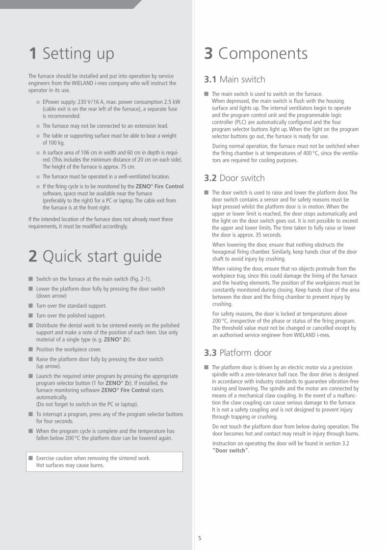
3 Components3.1 Main switch
� The main switch is used to switch on the furnace.When depressed, the main switch is flush with the housingsurface and lights up. The internal ventilators begin to operateand the program control unit and the programmable logiccontroller (PLC) are automatically configured and the fourprogram selector buttons light up. When the light on the programselector buttons go out, the furnace is ready for use.
During normal operation, the furnace must not be switched whenthe firing chamber is at temperatures of 400 °C, since the ventila-tors are required for cooling purposes.
3.2 Door switch
� The door switch is used to raise and lower the platform door. Thedoor switch contains a sensor and for safety reasons must bekept pressed whilst the platform door is in motion. When theupper or lower limit is reached, the door stops automatically andthe light on the door switch goes out. It is not possible to exceedthe upper and lower limits. The time taken to fully raise or lowerthe door is approx. 35 seconds.
When lowering the door, ensure that nothing obstructs thehexagonal firing chamber. Similarly, keep hands clear of the doorshaft to avoid injury by crushing.
When raising the door, ensure that no objects protrude from theworkpiece tray, since this could damage the lining of the furnaceand the heating elements. The position of the workpieces must beconstantly monitored during closing. Keep hands clear of the areabetween the door and the firing chamber to prevent injury bycrushing.
For safety reasons, the door is locked at temperatures above200 °C, irrespective of the phase or status of the firing program.The threshold value must not be changed or cancelled except byan authorised service engineer from WIELAND i-mes.
3.3 Platform door
� The platform door is driven by an electric motor via a precisionspindle with a zero-tolerance ball race. The door drive is designedin accordance with industry standards to guarantee vibration-freeraising and lowering. The spindle and the motor are connected bymeans of a mechanical claw coupling. In the event of a malfunc-tion the claw coupling can cause serious damage to the furnace.It is not a safety coupling and is not designed to prevent injurythrough trapping or crushing.
Do not touch the platform door from below during operation. Thedoor becomes hot and contact may result in injury through burns.
Instruction on operating the door will be found in section 3.2"Door switch".
3.4 Program selector buttons
� The program selector buttons are used to launch the requiredprogram. When the firing program is running, the correspondingprogram selector button lights up.
Pressing any program selector button for four seconds interruptsthe firing program and resets the program control unit and theprogrammable logic controller (PLC).
In the event of a system error, all program selector buttons flashsimultaneously once per second. Should this occur, please call theZENO® Tec hotline.
3.5 Workpiece tray
� The workpiece holder is hexagonal in design and measures120 mm from side to side and 140 mm from corner to corner.The three vertical supports hold the standard support.
Ensure that no objects protrude over the sides of the workpieceholder. Only products supplied or approved by WIELAND i-mesmay be placed on the workpiece holder. Ensure that the work-piece holder, the furnace lining and the heating element are notsubjected to extreme physical or chemical conditions which maydamage them.
The insulation of the furnace consists of oxide ceramic filamentsvacuum formed into plates and is intended exclusively for the firingof oxide ceramics such as yttrium stabilised zirconium oxide(Y2O3-ZrO2) or aluminium oxide (Al2O3). Organic binding agents,alkalis, chlorides, nitrides and other salts can corrode the insulationand the heating elements and may seriously damage them bycausing chemical reactions resulting in a reduction of the meltingpoint.
The use of incorrect firing auxiliaries and inserting chemicallyaggressive items into the furnace may invalidate the guarantee.Please consult a member of our specialist team before using anyauxiliaries other than those approved or supplied by WIELANDi-mes.
You will find instructions and procedure for loading the furnace insections 3.7 "Operating volume" and section 4 "Loading thefurnace".
3.6 Cooling air intake
� Air vents are fitted on both sides of the furnace housing. Theinternal ventilators draw in cool air through these vents duringoperation.
The cooling air vents must not be obstructed or covered. Observethe minimum distance of 20 cm on each side to cold items ofequipment and at least 1 m all round to hot equipment. Theeffects of any hot equipment must be investigated on a case-by-case basis.
For safety reasons, the insulation and cooling system of the fur-naces is designed so that the surface temperature of the housingand the firing chamber does not exceed 60 °C if cooling air ofmax. 25 °C is drawn in without obstruction through the air vents.
Ambient temperatures of 30 °C or more, cooling air which isheated by an external heat source or covered or obstructed airintake vents can lead to excessive surface temperatures which inturn increase the danger of injury from burns on contact, maycause the furnace to overheat and consequently result in minoror serious damage to the furnace and in extreme cases, fire.
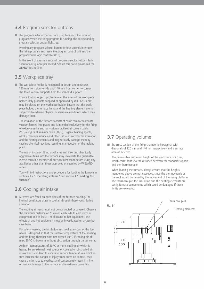
3.7 Operating volume
� the cross section of the firing chamber is hexagonal withdiagonals of 120 mm and 140 mm respectively and a surfacearea of 125 cm2.
The permissible maximum height of the workpiece is 5.5 cm,which corresponds to the distance between the standard supportand the thermocouple.
When loading the furnace, always ensure that the heightsmentioned above are not exceeded, since the thermocouple orthe roof would be raised by the movement of the rising platform.The thermocouple, the insulation and the heating elements arecostly furnace components which could be damaged if theselimits are exceeded.
6
Heating elements
ThermocouplesFig. 3-1
7
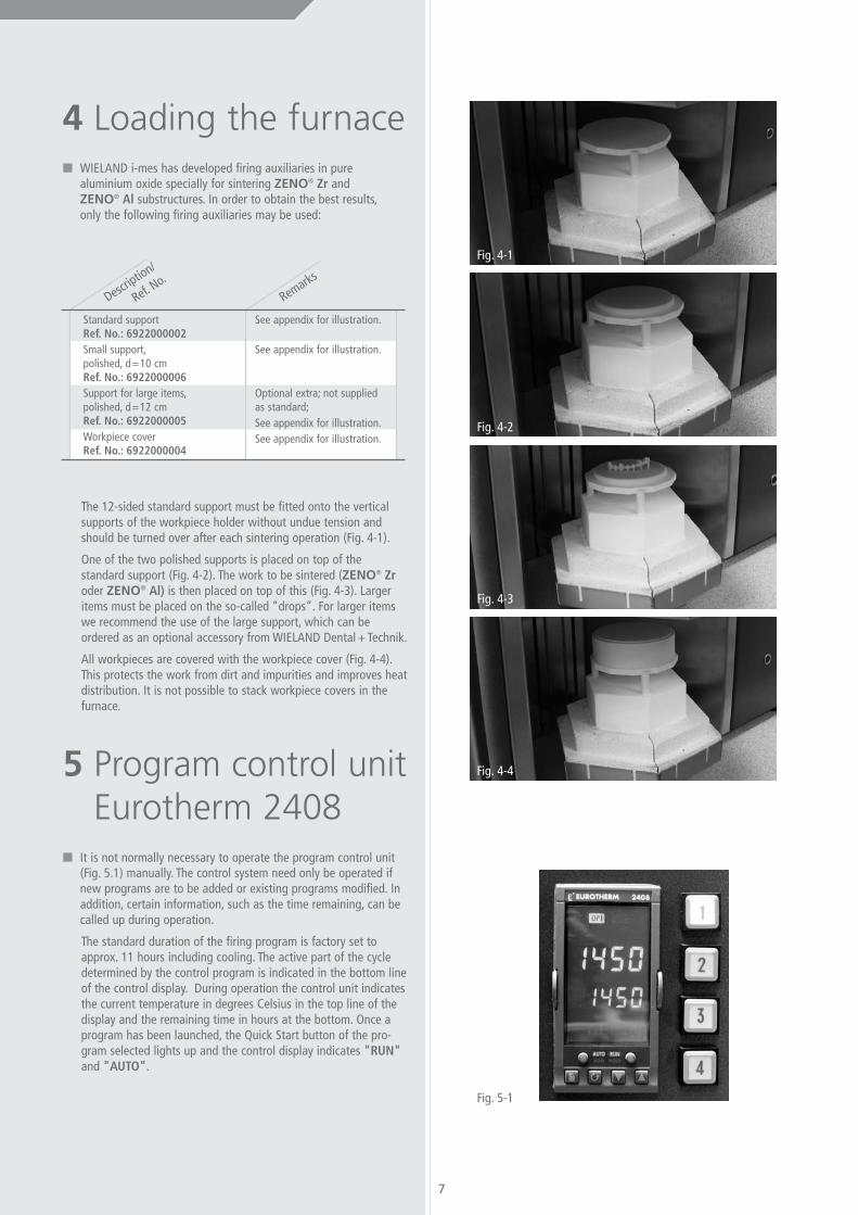
4 Loading the furnace� WIELAND i-mes has developed firing auxiliaries in pure
aluminium oxide specially for sintering ZENO® Zr andZENO® Al substructures. In order to obtain the best results,only the following firing auxiliaries may be used:
The 12-sided standard support must be fitted onto the verticalsupports of the workpiece holder without undue tension andshould be turned over after each sintering operation (Fig. 4-1).
One of the two polished supports is placed on top of thestandard support (Fig. 4-2). The work to be sintered (ZENO® Zroder ZENO® Al) is then placed on top of this (Fig. 4-3). Largeritems must be placed on the so-called “drops”. For larger itemswe recommend the use of the large support, which can beordered as an optional accessory from WIELAND Dental + Technik.
All workpieces are covered with the workpiece cover (Fig. 4-4).This protects the work from dirt and impurities and improves heatdistribution. It is not possible to stack workpiece covers in thefurnace.
5 Program control unitEurotherm 2408
� It is not normally necessary to operate the program control unit(Fig. 5.1) manually. The control system need only be operated ifnew programs are to be added or existing programs modified. Inaddition, certain information, such as the time remaining, can becalled up during operation.
The standard duration of the firing program is factory set toapprox. 11 hours including cooling. The active part of the cycledetermined by the control program is indicated in the bottom lineof the control display. During operation the control unit indicatesthe current temperature in degrees Celsius in the top line of thedisplay and the remaining time in hours at the bottom. Once aprogram has been launched, the Quick Start button of the pro-gram selected lights up and the control display indicates "RUN"and "AUTO".
Remarks
Description/
Ref. No.
See appendix for illustration.
See appendix for illustration.
Optional extra; not suppliedas standard;See appendix for illustration.See appendix for illustration.
Standard supportRef. No.: 6922000002Small support,polished, d=10 cmRef. No.: 6922000006Support for large items,polished, d=12 cmRef. No.: 6922000005Workpiece coverRef. No.: 6922000004
Fig. 4-1
Fig. 4-2
Fig. 4-3
Fig. 4-4
Fig. 5-1

� The following tables are intended as an introduction to thesystematic handling of the program control unit illustrated on the basis of the factory-set standard program.
Display
Remarks
Button
Temperature 1,450 °C, remaining time 2.8 hours;top level display
Temperature in degrees Celsius (displayed only briefly)Press button twice within 2 seconds
Output power 56.2 %Furnace operating at 56.2 % of its maximum output power
Set pointTarget temperature set to 1,450 °C
Press buttons together to enter top level display;temperature 1,450 °C, time remaining 2.8 hours
Calling up the furnace parameters during operation
2 x in 2 seconds
Display
Remarks
Button
Temperature 1,450 °C, time remaining 2.8 hours;top level display
Temperature in degrees Celsius (displayed only briefly)Press button twice within 2 seconds
Run ListList of operating parameters
Program 1 (programs 1 to 4 can be displayed;currently program 1)
Program Set pointThe target temperature is set to 1,450 °C
Cycle number 0 (number of cycles remaining)No further program launch upon termination of program
Segment 2 (segments 1 to 16 can be displayed)Segment 2 is currently running
Segment type Dwell (hold segment type)Hold segment (may also be a ramp: STYP/RAMP)
Segment time hour (remaining time of segment in hours)(Displays for one second only and changes automatically.)
Segment time 1.8The remaining time of the segment is 1.8 hours
Program time hour (remaining program time in hours)(Displays for one second only and changes automatically.)
Program time 4.1The remaining program time is 4.1 hours
Press buttons together to return to top level displayTemperature 1,450 °C; time remaining 2.8 hours; top level display
Calling up the operating parameters during operation
2 x in 2 seconds
Wait for 2 seconds
Wait for 2 seconds

9
Display
Remarks
Button
Temperature 1,450 °C; time remaining 2.8 hours);top level display
Temperature in degrees Celsius (displayed only briefly)Press button twice within 2 seconds
Run ListList of operating parameters
Program listList of program parameters
Program 1 (Programs 1 to 4 can be displayed)Program 1 is currently running. (Compare with illuminated buttons 1 to 4)
The program number of the program to be checked can be selectedby using the “up” and “down” arrows
Hold back offThe hold back or “target value brake” is switched off (e.g. for large furnaces)
Hold back value 0The “target value brake” is set to 0
Ramp unit hourDisplays ramps as a factor in degrees Celsius per hour
Dwell unit hourDisplays the dwell (holding) time in hours
Cycle number 1Cycle number 1 is selected and the program is set to run once
Segment number 1Displays the parameters and values of segment 1
Type ramp rate in degrees Celsius per hour.The segment is a ramp; the value is a rate
Target 900The target value is 900 degrees Celsius (“… up to a value of …)
Rate 600.0The rate is 600 °C per hour (“… at a rate of …”)
Segment number 2Displays the parameters and values of segment 2
Type dwellThe segment is a dwell or holding time
Duration hourThe duration of the dwell time in hours. Displays for one second only then changes automatically
Duration 0.5The dwell time is 30 minutes
Segment number 3Displays the values and parameters of segment 3
Type ramp rateThe type ramp rate in degrees Celsius per hour. The segment is a ramp; the value is a rate
Target 1450The target temperature of the ramp is 1450 °C (“… up to the value of …”)
Calling up the program parameters during program execution
2 x in 2 seconds
or
10
Display
Remarks
Button
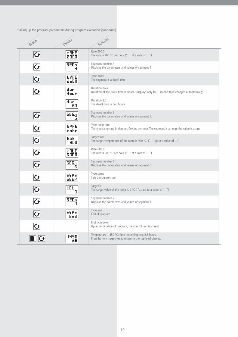
Rate 200.0The rate is 200 °C per hour (“… at a rate of …”)
Segment number 4Displays the parameters and values of segment 4
Type dwellThe segment is a dwell time
Duration hourDuration of the dwell time in hours. (Displays only for 1 second then changes automatically)
Duration 2.0The dwell time is two hours
Segment number 5Displays the parameters and values of segment 5.
Type ramp rateThe type ramp rate in degrees Celsius per hour. The segment is a ramp; the value is a rate
Target 900The target temperature of the ramp is 900 °C. (“… up to a value of …”)
Rate 600.0The rate is 600 °C per hour (“… at a rate of …”)
Segment number 6Displays the parameters and values of segment 6
Type setupSets a program step.
Target 0The target value of the ramp is 0 °C ( “… up to a value of …”)
Segment number 7Displays the parameters and values of segment 7
Type endEnd of program
End type dwellUpon termination of program, the control unit is at rest
Temperature 1,450 °C; time remaining, e.g. 2.8 hours.Press buttons together to return to the top level display.
Calling up the program parameters during program execution (continued)

11
Display
Remarks
Button
20 / 0.0Furnace temperature is 20 °C; time remaining is 0.0 hours
Temperature in degrees Celsius (only displayed briefly)Press button twice within two seconds
run / LiStLists the operating parameters
ProG / LiStLists the program parameters
PrG.n / 1Program number 1
Use the arrow buttons to select program 1.Display flashes to confirm.
Entering the programming level
2 x in 2 seconds
Display
Remarks
Button
Hb / OFFHold back / off
Use the arrow buttons to set the target value hold back function to OFFDisplay flashes once to confirm
Hb V / 0Use the arrow buttons to set the holdback value to 0
Display flashes once to confirm
rmP.U / HourUse the arrow buttons to setthe ramp unit to Hour
Display flashes once to confirm
dwL.U / HourUse the arrow buttons to setthe dwell unit to Hour
Display flashes once to confirm
CYC.n / 1Use the arrow buttons to setthe cycle number to 1
Display flashes once to confirm
Entering program parameters
or
or
or
or
or
or

12
Display
Remarks
Button
SEG.n / 1Segment number 1
Use arrow buttons to select segment 1Display flashes once to confirm
tYPE / rmP.rType = ramp rate
Use arrow buttons to set to rmP.rDisplay flashes once to confirm
tGt / 900Target = 900 °C
Use arrow buttons to set to 900Display flashes once to confirm
rAtE / 600.0Rate = 600 °C per hour
Use arrow buttons to set to 600Display flashes once to confirm
Entering values for segment 1 ramp
or
or
or
or
Display
Remarks
Button
SEG.n / 2Segment number 2
Use arrow buttons to select segment 2Display flashes once to confirm
tYPE / dwEllType = dwell
Use arrow buttons to set type to dwEllDisplay flashes once to confirm
dur / HourDuration hour
Displays only for 1 second and changes automatically
dur / 0.5Duration 0.5 hours = 30 minutes
Use arrow buttons to set to 0.5Display flashes once to confirm
Entering values for segment 2 dwell time
or
or
or

13
Display
Remarks
Button
SEG.n / 3Segment number 3
Use arrow buttons to select segment 3.Display flashes once to confirm.
tYPE / rmP.rType = ramp rate
Use arrow buttons to set to rmP.r.Display flashes once to confirm.
tGt / 1450Target = 1450 °C
Use arrow buttons to set to 1450Display flashes once to confirm.
rAtE / 200.0Rate = 200 °C per hour
Use arrow buttons to set to 200.Display flashes once to confirm.
Entering values for segment 3 ramp
or
or
or
or
Display
Remarks
Button
SEG.n / 4Segment number 4
Use arrow buttons to select segment 4.Display flashes once to confirm.
tYPE / dwEllType = dwell
Use arrow buttons to set to dwEll.Display flashes once to confirm.
dur / HourDuration unit = hour
Displays only for one second then changes automatically.
dur / 2.0Duration = 2 hours
Use arrow buttons to set to 2.0.Display flashes once to confirm.
Entering values for segment 4 dwell
or
or
or

14
Display
Remarks
Button
SEG.n / 5Segment number 5
Use arrow buttons to select segment 5Display flashes once to confirm
tYPE / rmP.rType = ramp rate
Use arrow buttons to set to rmP.rDisplay flashes once to confirm
tGt / 900Target = 900 °C
Use arrow buttons to set to 900Display flashes once to confirm
rAtE / 600.0Rate = 600 °C per hour
Use arrow buttons to set to 600Display flashes once to confirm
Entering values for segment 5 ramp
or
or
or
or
or
or
or
or
15
Display
Remarks
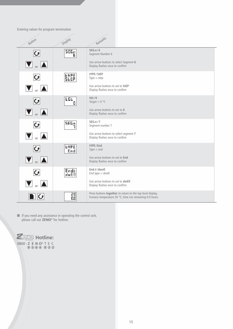
Button
SEG.n / 6Segment Number 6
Use arrow buttons to select Segment 6Display flashes once to confirm
tYPE / StEPType = step
Use arrow buttons to set to StEPDisplay flashes once to confirm
tGt / 0Target = 0 °C
Use arrow buttons to set to 0Display flashes once to confirm
SEG.n / 7Segment number 7
Use arrow buttons to select segment 7Display flashes once to confirm
tYPE / EndType = end
Use arrow buttons to set to EndDisplay flashes once to confirm
End.t / dwellEnd type = dwell
Use arrow buttons to set to dwEllDisplay flashes once to confirm
Press buttons together to return to the top level display.Furnace temperature 20 °C; time run remaining 0.0 hours.
Entering values for program termination
or
or
� If you need any assistance in operating the control unit,please call our ZENO® Tec hotline:
8 3 20800 - Z E N O® T E C
9 3 6 6
Hotline:

16
7 Technicalspecifications
1720 °C
1.25 litres
120/140 x 100 mm
230 V
16 A
2.5 kW
Maximum temperature
Net volume
Net dimensions, diameter x height
Power supply
Maximum power consumption
Maximum output
8 Appendix� Fig. 8-1:
Standard supportRef. No.: 6922000002
� Fig. 8-2:Small support, polished, d=10 cmRef. No.: 6922000006
� Fig. 8-3:Support for large items, polished, d=12 cmRef. No.: 6922000005
� Fig. 8-4:Workpiece coverRef. No.: 6922000004
6 Troubleshooting� In the event of a problem with the furnace, please call our
ZENO® Tec hotline
With your assistance, most faults can be identified on thetelephone and many can be rectified by the user acting on our instructions.
In all other cases of faults occurring or repair becomingnecessary, a visit from our service engineer is required.
Fig. 8-1
Fig. 8-2
Fig. 8-3
Fig. 8-4
8 3 20800 - Z E N O® T E C
9 3 6 6
Hotline: