zeolites in voc abatement and industrial waste gas ... · zeolites in voc abatement and industrial...
TRANSCRIPT
Claudia Arnold: “Zeolites in VOC Abatement and Industrial Waste Gas Purification.” From: “Zeolites in Chemical Engineering”, ISBN 978-3-902655-08-0
Zeolites in VOC Abatement and Industrial Waste GasPurification
Scope of this chapter
The scope of this chapter is not to give a guide on adsorber design or adsorption technique, nor to be a general waste gas purification manual. There are other excellent sources for this kind of information, see e. g. [1], [2]. Instead, the most important points specific to the use ofzeolites in adsorptive waste gas purification shall be covered.
When, and when not, zeolites are suited
The scope of any waste gas purification technique is to decontaminate a given exhaust air stream down to the legally required threshold value and to do this with as little negative effect on the upstream processes as possible. Adsorption (with any adsorbent) is only one of many methods of waste gas purification. The alternatives to adsorption will not be discussed here. Inshort, adsorption is usually chosen when one or several of the following conditions apply:
• The concentration of the contaminants is too low for cost-effective combustion or con-densation, yet too high for biological abatement techniques of any kind.
• Combustion of the contaminant(s) is problematic, e. g. for halogenated or nitrogen-con-taining compounds, or their biodegradability is low.
• The chemical nature of the contaminant renders it unsuitable for catalytic oxidation, biological abatement or for scrubbing.
• The waste gas stream is of fluctuating concentrations, or is laden with volatile organic compounds only sporadically.
There are many adsorbents on the market, their prices ranging from cents per kilogram up to more than a hundred Euros. Some adsorbents, like zeolites, polymeric resins and some acti-vated carbon qualities, can be regenerated in situ by a dedicated regeneration system built into the plant. Activated carbon, if regenerated at all, is mostly shipped back to the producer tobe reactivated there. Other adsorbents, like clay minerals and simple carbon qualities, are not regenerated at all.
Chemical stability
Zeolites for “normal” waste gas purification – that is, purification of air with its ambient mois-ture present – are so-called hydrophobic zeolites and cost between 20 and 35 Euros/kg. Their high prime cost makes in situ-regeneration mandatory. This will limit their application to such volatile organic compounds that will come off the zeolite with relative ease, and to such condi-tions that will not in any way harm the adsorbent. Accordingly, zeolites are suitable adsorbentsfor
• volatile molecules, like most solvents, with a boiling point well below 200 °C
• molecules that are stable, do not polymerize and are not prone to chemical reactions in the adsorbed state
• molecules that are stable to acids, since all hydrophobic zeolites, not only the avowed catalysts, have acidic centers
• molecules to which hydrophobic zeolites are stable. This excludes especially alkaline compounds such as amines (which are very often rather high-boiling, too). These com-ponents have to be removed prior to adsorption, which is usually achieved by a liquid
(c) Dr. Arnold Chemie-Beratung 2014 www.arnold-chemie.de
Claudia Arnold: “Zeolites in VOC Abatement and Industrial Waste Gas Purification.” From: “Zeolites in Chemical Engineering”, ISBN 978-3-902655-08-0
scrub.
Size exclusion
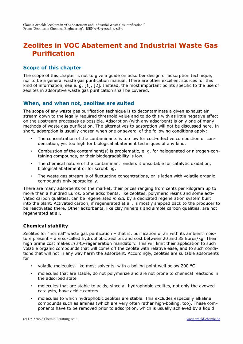
Due to the microporous structure of the zeolites, molecules that are too big for the pore size will be excluded. Though a very small amount of adsorption might still occur on the surface and binder portion of the adsorbent, such zeolite-adsorbate-combinations are usually not suit-able. For some examples of size exclusion, refer to fig. 1. This chart ends with the zeolite Faujasite, whose pore windows have a diameter of 0,9 nm. Accordingly, branched C12 to C14-compounds are among the largest molecules that can be adsorbed, and waste gas streams containing larger molecules can be ruled out.
Though so-called mesoporous zeolites(materials with pore sizes around 2 nm and larger) exist, they are not yetavailable in technical quantities. Moreover, it is only at rather high partial pressures that their superior maximum adsorption capacity can be utilized. In adsorption experiments with benzene, MCM-41 exhibited a maximum adsorption capacity that was three times that of hydrophobic zeolite Y, but only at vapor saturation point, corresponding to 320 g/m³. At 10% of this concentration (32 g/m³), the adsorption capacity of MCM-41 had dropped far below that of zeolite Y [12]. This effect is due to the fact that the inner surface of MCM-41 is lower than that of zeolite Y, while its pore volume is higher.
Aerosols
Conditions that are not suitable for waste gas purification with zeolites include waste gas streams that, due to the presence of aerosols, require too much mechanical pretreatment. Aerosols may come in various forms, or any mixtures thereof:
• Solid particles cover the zeolite pellets with an
impenetrable (and often sticky) coat. Over time, solid aerosols can block significant portions of the space between the zeolite particles.
• Droplets of liquid water will lead to mechanical destruction of the zeolite pellets. Thoughthe zeolites themselves are hydrophobic, their binder (mostly clay) is not. Soaking of the particles can lead to their bursting during regeneration at high temperatures. Too much moisture on the pellets – anything that leads to condensation – also favors recrystallization of the clay binder, leading to a significant reduction of its mesopore volume and, therefore, its transport properties [52], [53].
(c) Dr. Arnold Chemie-Beratung 2014 www.arnold-chemie.de
Fig. 1: Zeolite pore sizes and kinetic diameter of molecules
Claudia Arnold: “Zeolites in VOC Abatement and Industrial Waste Gas Purification.” From: “Zeolites in Chemical Engineering”, ISBN 978-3-902655-08-0
• Liquid droplets formed of solvent will lead to a local “overloading” of the zeolite, the worst consequence of this being self-ignition. These effects will be discussed in more detail later.
Basic types of adsorption apparatus
Fixed bed adsorbers
Though more sophisticated systems exist, fixed beds are still the working horses of adsorption technology. Their construction is rather simple, the attrition of the zeolite low (but not zero). The drawback of this plant type is the need for redundancy – in most cases, at least two beds will be needed to provide continuous waste gas purification.
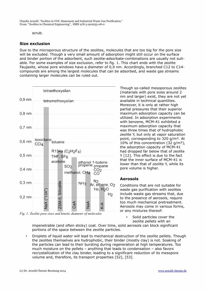
Fig. 2 shows a typical double bed adsorption unit in a simplified form. Double beds are usu-ally needed if working hours are longer than one shift per day. One adsorber is used for pol-lution control, while the other is being regene-rated. In this design, the waste gas stream passes a particle filter, then (only in some ca-ses) a simple activated carbon or zeolite filter that is not regenerated and serves to smooth out concentration peaks. In the next step the gas stream passes the zeolite filter, after which it can go directly to the stack.
To regenerate an adsorber bed, hot gas is blown through it, with a lower volumetric flow than during the adsorption phase. To avoid ignition, the hot gas can be nitrogen. In the depicted example however, the concentrated desorbate is to be oxidized on a catalyst bed, therefore air is needed as the desorption gas. The desorption conditions are adjusted so that the catalyst works autothermally, without the need for additional fuel gas, but that the desorbate's concentration remains well below
explosion limit (usually at 25% below). Concentration ratios of about 1:6 are the most typical. Special measures have to be taken to avoid the hazard of fires.
After the concentrated desorbate passes the catalyst, it goes through a recuperator to help warm up fresh desorption gas. After this, it is discharged via the stack.
If there is abundant time before the adsorber must go into operation again, it can be left to cool on its own. In insulated adsorbers containing two to three tons of material this can take a day or two. In most cases, cooling of the bed will be forced by blowing fresh air through it.
Rotary wheels
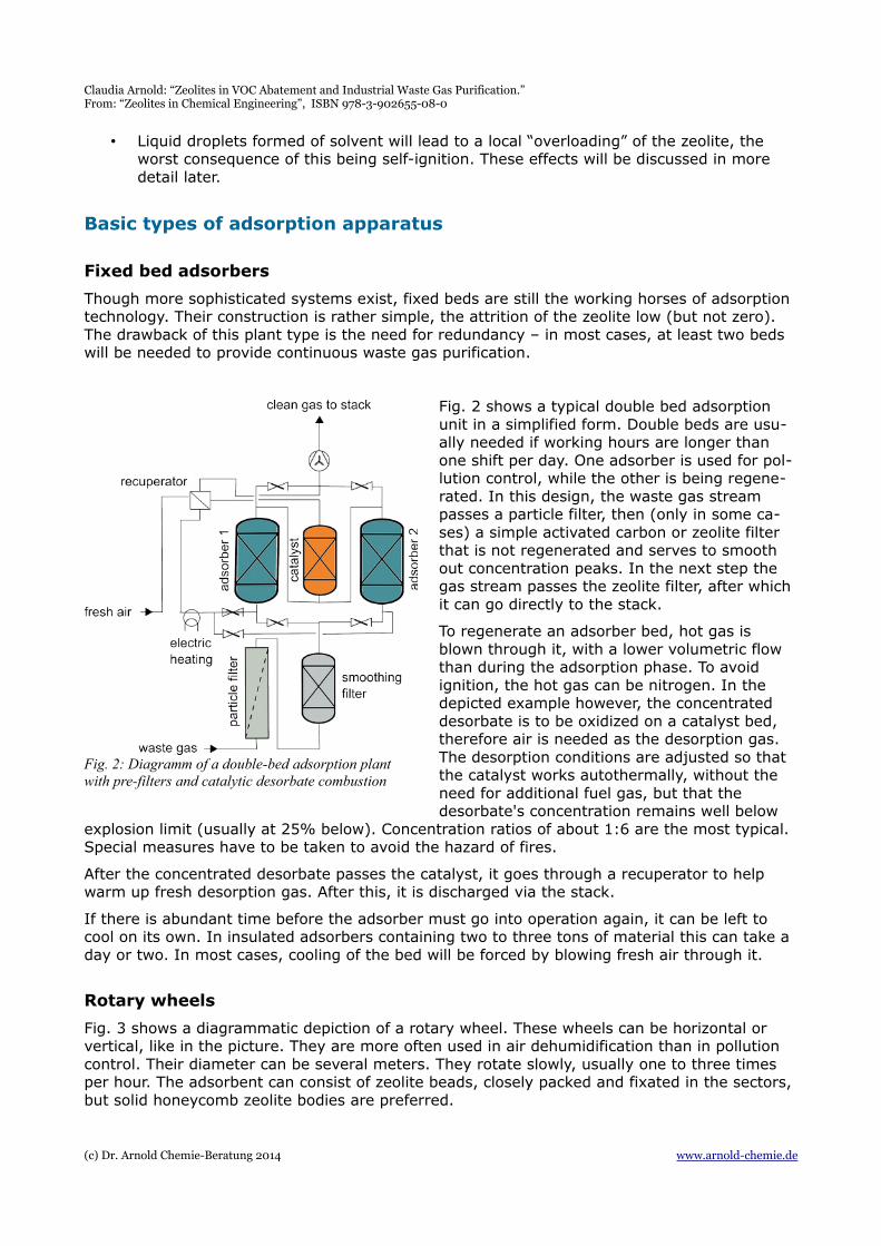
Fig. 3 shows a diagrammatic depiction of a rotary wheel. These wheels can be horizontal or vertical, like in the picture. They are more often used in air dehumidification than in pollution control. Their diameter can be several meters. They rotate slowly, usually one to three times per hour. The adsorbent can consist of zeolite beads, closely packed and fixated in the sectors, but solid honeycomb zeolite bodies are preferred.
(c) Dr. Arnold Chemie-Beratung 2014 www.arnold-chemie.de
Fig. 2: Diagramm of a double-bed adsorption plant with pre-filters and catalytic desorbate combustion
Claudia Arnold: “Zeolites in VOC Abatement and Industrial Waste Gas Purification.” From: “Zeolites in Chemical Engineering”, ISBN 978-3-902655-08-0
At least one quarter of the wheel is usually dedicated to re-generation by hot gas desorpti-on and subsequent cooling. The desorbate is a concentrate, like in the case of a fixed bed, and has to be treated by a suitable method.
The remaining three quarters of the wheel form the operating adsorption part. The wheel moves continuously (in some more ambitious designs it jumpsto the next sector and then stands still), the regeneration hoods covering and uncovering one sector after the other. The speed of rotation has to be
adjusted so that no individual sector stays within the polluted gas stream too long, because this would lead to breakthrough.
While the adsorption wheel offers the advantage of a quasi-continuous operation, there are several drawbacks to this design:
• The hoods that move over the sectors should seal the air passages formed thereby to avoid the mixing of polluted exhaust air with desorption air, as this reduces the effectiv-ity. Technically, this is not easy and is rarely achieved. It is achieved only roughly if the wheel moves continuosly.
• The individual sectors of the wheel (which can be viewed as individual fixed bed adsor-bers) are shallow. The adsorption wheel is not very fit to deal with concentration peaks which tend to break through rather quickly. Some adjustments can be made by increas-ing the speed of the wheel, but this is limited by the maximum achievable regeneration and cooling rate.
These are the reasons why rotary wheels are not preferred for environmental technology, but rather for dehumidification, because in the latter case, a breakthrough here and there and in-consistent effectivity are not so threatening.
Necessary data for adsorber design and zeolite selection
The technical data necessary for adsorber design are the same as for any other adsorbents andcontain numbers such as volumetric flow rate, inlet temperature and hours of operation.
Volumetric flow
As with any adsorbent, the volumetric flow determines the necessary cross sectional area of the adsorbent filter. With most zeolites, acceptable superficial velocities are between 0,01 and 0,9 m/s. With lower superficial velocities, the flow becomes laminar instead of turbulent, lead-ing to decreased mass transfer into the zeolite particle and increased hazard of self-ignition. Above 0,9 m/s, the actual flow speed in the pinched areas between single pellets can exceed the speed of sound, leading to their mechanical destruction over time. Depending on the thick-ness of the zeolite layer, the fixed bed might also fluidize, which is undesirable, as it destroys the pellets through attrition.
(c) Dr. Arnold Chemie-Beratung 2014 www.arnold-chemie.de
Fig. 3: Wheel-type adsorption unit
Claudia Arnold: “Zeolites in VOC Abatement and Industrial Waste Gas Purification.” From: “Zeolites in Chemical Engineering”, ISBN 978-3-902655-08-0
The acceptable volumetric flow varies slightly with the shape of the pellets. Today, zeolite pel-lets for fixed bed applications are mostly in the shape of almost perfectly spherical beads in rather uniform sizes (e. g. 1 -2 mm and 2 – 5 mm fractions), but other shapes, such as the irregularly rotund clots known from silica gel, small rods and more complicated shapes, like tri-lobed rods, are also on the market. The shape will influence the pressure drop, the superficial velocity at which turbulent flow sets in, and the point at which sonic destruction begins. For exact information, one has to apply to the manufacturer.
Temperature and relative humidity
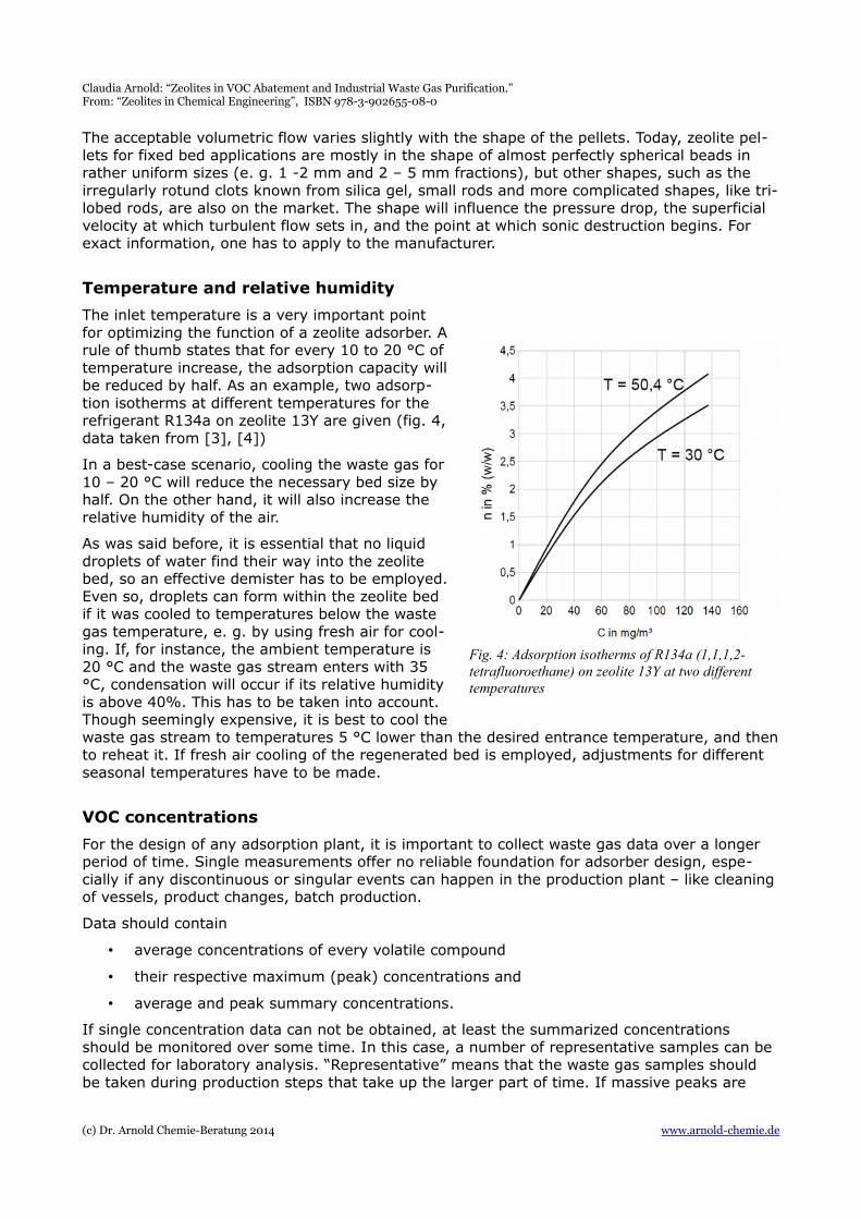
The inlet temperature is a very important pointfor optimizing the function of a zeolite adsorber. Arule of thumb states that for every 10 to 20 °C oftemperature increase, the adsorption capacity willbe reduced by half. As an example, two adsorp-tion isotherms at different temperatures for therefrigerant R134a on zeolite 13Y are given (fig. 4,data taken from [3], [4])
In a best-case scenario, cooling the waste gas for10 – 20 °C will reduce the necessary bed size byhalf. On the other hand, it will also increase therelative humidity of the air.
As was said before, it is essential that no liquiddroplets of water find their way into the zeolitebed, so an effective demister has to be employed.Even so, droplets can form within the zeolite bedif it was cooled to temperatures below the wastegas temperature, e. g. by using fresh air for cool-ing. If, for instance, the ambient temperature is20 °C and the waste gas stream enters with 35°C, condensation will occur if its relative humidityis above 40%. This has to be taken into account.Though seemingly expensive, it is best to cool thewaste gas stream to temperatures 5 °C lower than the desired entrance temperature, and thento reheat it. If fresh air cooling of the regenerated bed is employed, adjustments for different seasonal temperatures have to be made.
VOC concentrations
For the design of any adsorption plant, it is important to collect waste gas data over a longer period of time. Single measurements offer no reliable foundation for adsorber design, espe-cially if any discontinuous or singular events can happen in the production plant – like cleaningof vessels, product changes, batch production.
Data should contain
• average concentrations of every volatile compound
• their respective maximum (peak) concentrations and
• average and peak summary concentrations.
If single concentration data can not be obtained, at least the summarized concentrations should be monitored over some time. In this case, a number of representative samples can be collected for laboratory analysis. “Representative” means that the waste gas samples should be taken during production steps that take up the larger part of time. If massive peaks are
(c) Dr. Arnold Chemie-Beratung 2014 www.arnold-chemie.de
Fig. 4: Adsorption isotherms of R134a (1,1,1,2-tetrafluoroethane) on zeolite 13Y at two different temperatures
Claudia Arnold: “Zeolites in VOC Abatement and Industrial Waste Gas Purification.” From: “Zeolites in Chemical Engineering”, ISBN 978-3-902655-08-0
expected to occur, the design has to accommodate these, otherwise breakthrough events will become a daily occurrence.
Chemical and physicochemical properties of the VOCs
The most important questions about any chemical to be adsorbed on zeolite– besides its gen-eral adsorption behavior – are:
• Is the chemical volatile enough to be desorbed within a cost-effective temperature range?
• Will it harm the zeolite?
• Will it react on the zeolite, leading to fouling or reactive hazards?
The first question is answered easily by finding the molecule's boiling point and vapor pressuredata (MSDSs – material safety data sheets - are good sources for this type of information).
As to the second question, hydrophobic zeolites are harmed almost exclusively by alkaline sub-stances only, that is to say, amines, nitrogen containing heterocyclic compounds and some others. The pH of a compound or of its aqueous solution is indicated on an MSDS and can serve to give an idea of its damaging potential to the zeolite.
The third question is more difficult to answer, and likewise difficult to test experimentally. Poly-merizations, reactions on zeolite or the formation of hot spots with concurring thermal run-aways unhappily are subject to “Finagle's Law”. Finagle's Law, or the “demo effect”, means thatit will not be easy to reproduce the incidents reliably on laboratory scale, since the conditions within the bed are not understood in enough detail. A production-size plant may run without interruption for years, and then, seemingly without any outward reason, an incident occurs. However, there are some substances and some adsorber configurations for which reactive ha-zards are larger than for others. These will be discussed in detail later.
Adsorption and co-adsorption data
To achieve the highest adsorption capacity for the zeolite mass and volume one packs into one's adsorbers, the best zeolite for the application, or the best mixture of zeolites, has to be chosen. The necessary informations are contained in adsorption isotherms, or adsorption capacity data, for single zeolite-adsorbate pairs.
Normally manufacturers give the adsorption capacity of a zeolite as “maximal capacity” or “total capacity”. This is the adsorption capacity measured under a rather concentrated vapor ofthe solvent in question. These maximal capacities may be as high as 30% (w/w), which soundsgood, but can be very misleading.
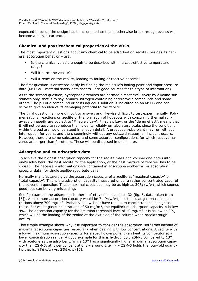
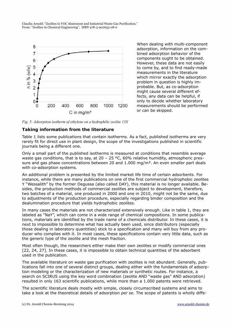
See for example the adsorption isotherm of ethylene on zeolite 13X (fig. 5, data taken from [5]). A maximum adsorption capacity would be 7,4%(w/w), but this is at gas phase concen-trations above 700 mg/m³. Probably one will not have to adsorb concentrations as high as those. For waste gas concentrations of 50 mg/m³, the equilibrium adsorption capacity is below 4%. The adsorption capacity for the emission threshold level of 20 mg/m³ it is as low as 2%, which will be the loading of the zeolite at the exit side of the column when breakthrough occurs.
This simple example shows why it is important to consider the adsorption isotherms instead of maximal adsorption capacities, especially when dealing with low concentrations. A zeolite with a lower maximum adsorption capacity for a specific component can beat its competitor at a lower concentration range. A good example for this is hydrophobic ZSM-5 compared to 13Y with acetone as the adsorbent: While 13Y has a significantly higher maximal adsorption capa-city than ZSM-5, at lower concentrations – around 2 g/m³ – ZSM-5 holds the four-fold quanti-ty, that is, 8%(w/w) vs. 2%(w/w) [6].
(c) Dr. Arnold Chemie-Beratung 2014 www.arnold-chemie.de
Claudia Arnold: “Zeolites in VOC Abatement and Industrial Waste Gas Purification.” From: “Zeolites in Chemical Engineering”, ISBN 978-3-902655-08-0
When dealing with multi-component adsorption, information on the com-bined adsorption behavior of the components ought to be obtained. However, these data are not easily to come by, and to find ready-made measurements in the literature which mirror exactly the adsorption problem in question is highly im-probable. But, as co-adsorption might cause several different ef-fects, any data can be helpful, if only to decide whether laboratory measurements should be performed or can be skipped.
Taking information from the literature
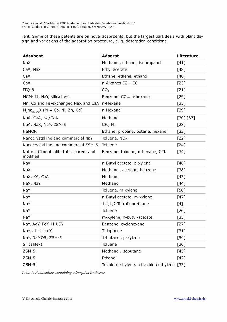
Table 1 lists some publications that contain isotherms. As a fact, published isotherms are very rarely fit for direct use in plant design, the scope of the investigations published in scientific journals being a different one.
Only a small part of the published isotherms is measured at conditions that resemble average waste gas conditions, that is to say, at 20 – 25 °C, 60% relative humidity, atmospheric pres-sure and gas phase concentrations between 20 and 1.000 mg/m³. An even smaller part deals with co-adsorption systems.
An additional problem is presented by the limited market life time of certain adsorbents. For instance, while there are many publications on one of the first commercial hydrophobic zeolitesY “Wessalith” by the former Degussa (also called DAY), this material is no longer available. Be-sides, the production methods of commercial zeolites are subject to development, therefore, two batches of a material, one produced in 2000 and one in 2010, might not be the same, due to adjustments of the production procedure, especially regarding binder composition and the dealumination procedure that yields hydrophobic zeolites.
In many cases the materials are not characterized extensively enough. Like in table 1, they arelabeled as “NaY”, which can come in a wide range of chemical compositions. In some publica-tions, materials are identified by the trade name of a chemicals distributor. In these cases, it isnext to impossible to determine what has actually been used, since distributors (especially those dealing in laboratory quantities) stick to a specification and many will buy from any pro-ducer who complies with it. In most cases, these specifications contain very little data, such asthe generic type of the zeolite and the mesh fraction.
Most often though, the researchers either make their own zeolites or modify commercial ones [22, 24, 27]. In these cases, it is impossible to obtain technical quantities of the adsorbent used in the publication.
The available literature on waste gas purification with zeolites is not abundant. Generally, pub-lications fall into one of several distinct groups, dealing either with the fundamentals of adsorp-tion modeling or the characterization of new materials or synthetic routes. For instance, a search on SCIRUS using the key word combination (zeolite AND “waste gas” AND adsorption) resulted in only 163 scientific publications, while more than a 1.000 patents were retrieved.
The scientific literature deals mostly with simple, closely circumscribed systems and aims to take a look at the theoretical details of adsorption per se. The scope of patents is wholly diffe-
(c) Dr. Arnold Chemie-Beratung 2014 www.arnold-chemie.de
Fig. 5: Adsorption isotherm of ethylene on a hydrophilic zeolite 13X
Claudia Arnold: “Zeolites in VOC Abatement and Industrial Waste Gas Purification.” From: “Zeolites in Chemical Engineering”, ISBN 978-3-902655-08-0
rent. Some of these patents are on novel adsorbents, but the largest part deals with plant de-sign and variations of the adsorption procedure, e. g. desorption conditions.
Adsobent Adsorpt Literature
NaX Methanol, ethanol, isopropanol [41]
CaA, NaX Ethyl acetate [48]
CaA Ethane, ethene, ethanol [40]
CaA n-Alkanes C2 – C6 [23]
ITQ-6 CO2 [21]
MCM-41, NaY, silicalite-1 Benzene, CCl4, n-hexane [29]
Mn, Co and Fe-exchanged NaX and CaA n-Hexane [35]
MxNa87-2xX (M = Co, Ni, Zn, Cd) n-Hexane [39]
NaA, CaA, Na/CaA Methane [30] [37]
NaA, NaX, NaY, ZSM-5 CF4, N2 [28]
NaMOR Ethane, propane, butane, hexane [32]
Nanocrystalline and commercial NaY Toluene, NO2 [22]
Nanocrystalline and commercial ZSM-5 Toluene [24]
Natural Clinoptilolite tuffs, parent and modified
Benzene, toluene, n-hexane, CCl4 [34]
NaX n-Butyl acetate, p-xylene [46]
NaX Methanol, acetone, benzene [38]
NaX, KA, CaA Methanol [43]
NaX, NaY Methanol [44]
NaY Toluene, m-xylene [58]
NaY n-Butyl acetate, m-xylene [47]
NaY 1,1,1,2-Tetrafluorethane [4]
NaY Toluene [26]
NaY m-Xylene, n-butyl-acetate [25]
NaY, AgY, PdY, H-USY Benzene, cyclohexane [27]
NaY, all-silica-Y Thiophene [31]
NaY, NaMOR, ZSM-5 1-butanol, p-xylene [54]
Silicalite-1 Toluene [36]
ZSM-5 Methanol, isobutane [45]
ZSM-5 Ethanol [42]
ZSM-5 Trichloroethylene, tetrachloroethylene [33]
Table 1: Publications containing adsorption isotherms
(c) Dr. Arnold Chemie-Beratung 2014 www.arnold-chemie.de
Claudia Arnold: “Zeolites in VOC Abatement and Industrial Waste Gas Purification.” From: “Zeolites in Chemical Engineering”, ISBN 978-3-902655-08-0
Selecting the best zeolite for a pollution control problem
Using a dedicated quality for adsorption purposes
It may sound trite to say “Use a quality expressly designed for adsorption purposes”, but it hashappened more than once that an acidic zeolitic catalyst has accidentally been used for pollu-tion control. With any but the most stable VOCs which do not require high desorption tempera-tures (e. g. propane) this is an almost certain recipe for disaster, leading to quick fouling and/ or self-ignition of the zeolite bed.
Size exclusion
If adsorption data for all the VOCs in question are available, there is of course no need to check size exclusion separately. In multi-purpose plants, zeolite 13Y is very much preferred as an adsorbent since it has the largest pores and will exclude the least number of components.
On the other hand, bigger is not automatically better. Small pores show larger enthalpies of adsorption for a given molecule. If a significant quantity of smaller molecules is present, such as methanol or acetone, adding some ZSM-5 to the mixture should be considered, as it is very effective at lower concentrations. Two different zeolites can be used in a mixed bed, or in sepa-rate beds, placing the variety with smaller pores upstream.
If in doubt, size exclusion can be checked into by looking up the kinetic diameter of the mole-cule in a database or handbook. Kinetic diameters can vary very much, depending upon the method for determination that has been used. Alternatively, the molecule can be modeled in a molecular editor and “measured”. This method gives an idea of its size, but is not very accu-rate. Longish molecules, like n-alkanes, might falsely present themselves as being easily ad-sorbable, while in reality their adsorption and diffusion into the zeolite pores is excessively slow due to the high probability of balled-up conformations.
The temperature also makes a difference, as a rising temperature increases both the effective zeolite pore size and the kinetic diameter of molecules, albeit not with the same rate. Therefore, a temperature window of adsorption might exist. These cases are rare, but can account for some of the differences between several sets of literature data.
If in doubt, it will always be best to find – or measure – adsorption isotherm data for the selec-tion of a suitable pore size.
Waste gas humidity
Normally, only hydrophobic zeolites are chosen for pollution control purposes. This excludes zeolite A varieties and some other types which can not be prepared in hydrophobic form. Hy-drophobic zeolites can handle moisture up to 95%. While at these high moisture contents theiradsorption capacity will drop somewhat, unlike activated carbon they do not show pore con-densation and pore blockage, thus the mass transport into the pores remains unhindered [49] (see [59] for adsorption isotherms of water on zeolite Y and activated carbon).
Theoretically, if only dry nitrogen and organic solvents, no ambient air, pass the adsorption unit, hydrophilic molecular sieve could be used. It is much less expensive than the hydrophobictype (10 – 30% of its price, depending on the specification), has very good adsorption proper-ties for a large range of organic molecules and a better resistance to alkaline substances.
In real life, though, one would have to exclude the ambient air most strictly, since water wouldaccumulate on the zeolite over time, reducing the adsorption capacity to zero [38]. Regenerat-ion would require temperatures well above 200 °C to expel the water effectively. Ambient moisture diffuses into the adsorption unit even against the direction of the gas stream. There-fore, only in some few exotic cases hydrophilic molecular sieve is used for waste gas purificat-
(c) Dr. Arnold Chemie-Beratung 2014 www.arnold-chemie.de
Claudia Arnold: “Zeolites in VOC Abatement and Industrial Waste Gas Purification.” From: “Zeolites in Chemical Engineering”, ISBN 978-3-902655-08-0
ion purposes. It is more commonly used in applications where a gas volume (e. g. argon) is to be regenerated within a closed circuit.
Pellet size
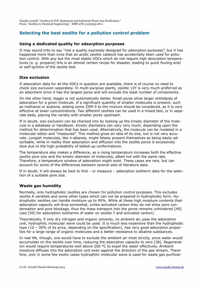
The tolerable pressure drop will be the most important factor when selecting the adsor-bent particle size. Though it feels counter-intuitive, the pellet size itself has a rather small influence on the diffusion time into thezeolite. This is due to the fact that the zeo-lite particles embedded in the binder matrix are of the same size, roughly 1 µm. Though one would think that larger particles need a longer time to be utilized “to the core”, in fact the longest distance of molecular diffu-sion is through the transport pores of the binder, which are meso- or macropores. Fig. 6 gives a schematic depiction of zeolite par-ticles with nanopores, embedded in a binder particle with mesopores.
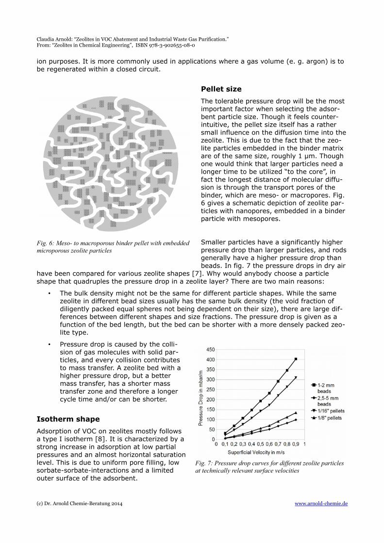
Smaller particles have a significantly higher pressure drop than larger particles, and rodsgenerally have a higher pressure drop than beads. In fig. 7 the pressure drops in dry air
have been compared for various zeolite shapes [7]. Why would anybody choose a particle shape that quadruples the pressure drop in a zeolite layer? There are two main reasons:
• The bulk density might not be the same for different particle shapes. While the same zeolite in different bead sizes usually has the same bulk density (the void fraction of diligently packed equal spheres not being dependent on their size), there are large dif-ferences between different shapes and size fractions. The pressure drop is given as a function of the bed length, but the bed can be shorter with a more densely packed zeo-lite type.
• Pressure drop is caused by the colli-sion of gas molecules with solid par-ticles, and every collision contributesto mass transfer. A zeolite bed with ahigher pressure drop, but a bettermass transfer, has a shorter masstransfer zone and therefore a longercycle time and/or can be shorter.
Isotherm shape
Adsorption of VOC on zeolites mostly followsa type I isotherm [8]. It is characterized by astrong increase in adsorption at low partialpressures and an almost horizontal saturationlevel. This is due to uniform pore filling, lowsorbate-sorbate-interactions and a limitedouter surface of the adsorbent.
(c) Dr. Arnold Chemie-Beratung 2014 www.arnold-chemie.de
Fig. 6: Meso- to macroporous binder pellet with embedded microporous zeolite particles
Fig. 7: Pressure drop curves for different zeolite particles at technically relevant surface velocities
Claudia Arnold: “Zeolites in VOC Abatement and Industrial Waste Gas Purification.” From: “Zeolites in Chemical Engineering”, ISBN 978-3-902655-08-0
However, this is not true for all organic molecules. With some rather volatile molecules, like methanol or methylene chloride, zeolite 13Y shows a more Henry-like behavior, that is, wide ranges of partial pressures in which there is an almost linear dependence between partial pres-sure and adsorption.
As an additional factor, the quantity of binder, which is at least around 5%, can amount to 12 –15% in specially stabilized zeolite beads. The binder (mostly clay) shows an entirely different adsorption behavior and overlays the pure zeolite isotherm to some degree.
It follows that the macroscopic shape of the adsorption isotherm can vary for a given organic molecule, not only with different zeolite types, but also with zeolites of the same type by dif-ferent manufacturers. As was already stated above, it is not the zeolite with the highest maxi-mum adsorption capacity that is best for a given application, but the one with the highest ad-sorption capacity at the expected concentration range in the waste gas.
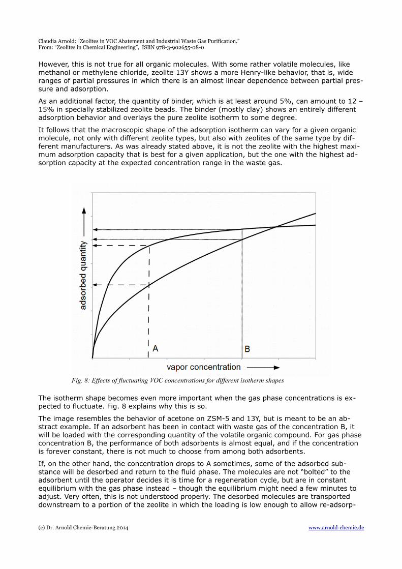
The isotherm shape becomes even more important when the gas phase concentrations is ex-pected to fluctuate. Fig. 8 explains why this is so.
The image resembles the behavior of acetone on ZSM-5 and 13Y, but is meant to be an ab-stract example. If an adsorbent has been in contact with waste gas of the concentration B, it will be loaded with the corresponding quantity of the volatile organic compound. For gas phaseconcentration B, the performance of both adsorbents is almost equal, and if the concentration is forever constant, there is not much to choose from among both adsorbents.
If, on the other hand, the concentration drops to A sometimes, some of the adsorbed sub-stance will be desorbed and return to the fluid phase. The molecules are not “bolted” to the adsorbent until the operator decides it is time for a regeneration cycle, but are in constant equilibrium with the gas phase instead – though the equilibrium might need a few minutes to adjust. Very often, this is not understood properly. The desorbed molecules are transported downstream to a portion of the zeolite in which the loading is low enough to allow re-adsorp-
(c) Dr. Arnold Chemie-Beratung 2014 www.arnold-chemie.de
Fig. 8: Effects of fluctuating VOC concentrations for different isotherm shapes
Claudia Arnold: “Zeolites in VOC Abatement and Industrial Waste Gas Purification.” From: “Zeolites in Chemical Engineering”, ISBN 978-3-902655-08-0
tion. This leads to a blurring of the mass transfer zone, which in turn leads to earlier break-through. The effect is much stronger in Henry-like isotherms than in type I isotherms, providedthe concentration range in question does not reach into the descending portion of the latter.
Co-adsorption effects
Only as a rare exception the waste gas purification plant will have to deal with one pollutant only. In most cases, there will be two, three or more solvents that make up the bulk mass, andsometimes a host of other organic molecules may appear in the waste gas part-time.
It is due to these complicated set-ups that “real” modeling of adsorption behavior is seldom used in adsorption plant design for pollution control. Mass and energy balance equations whichcan be drawn up for constant gas streams with simple compositions are impossible to formu-late – and to solve – for an adsorber that is to serve a multi-purpose plant. For an overview of adsorption models published in the literature refer to [1].
Nevertheless, the list of chemical substances should be looked over to see whether there are cases in which unwanted co-adsorption effects are probable.
Sometimes, two or more chemical species do not interact noticeably with one another on the zeolite and compete only passively for adsorption space: No co-adsorption effect is visible, breakthrough curves for a single component look as if the zeolite bed was diluted with inert material, breakthrough curves for the sum of organic compounds look like those for single compounds. This will be the case if the components have similar adsorption isotherms and do not tend to form complexes with one another.
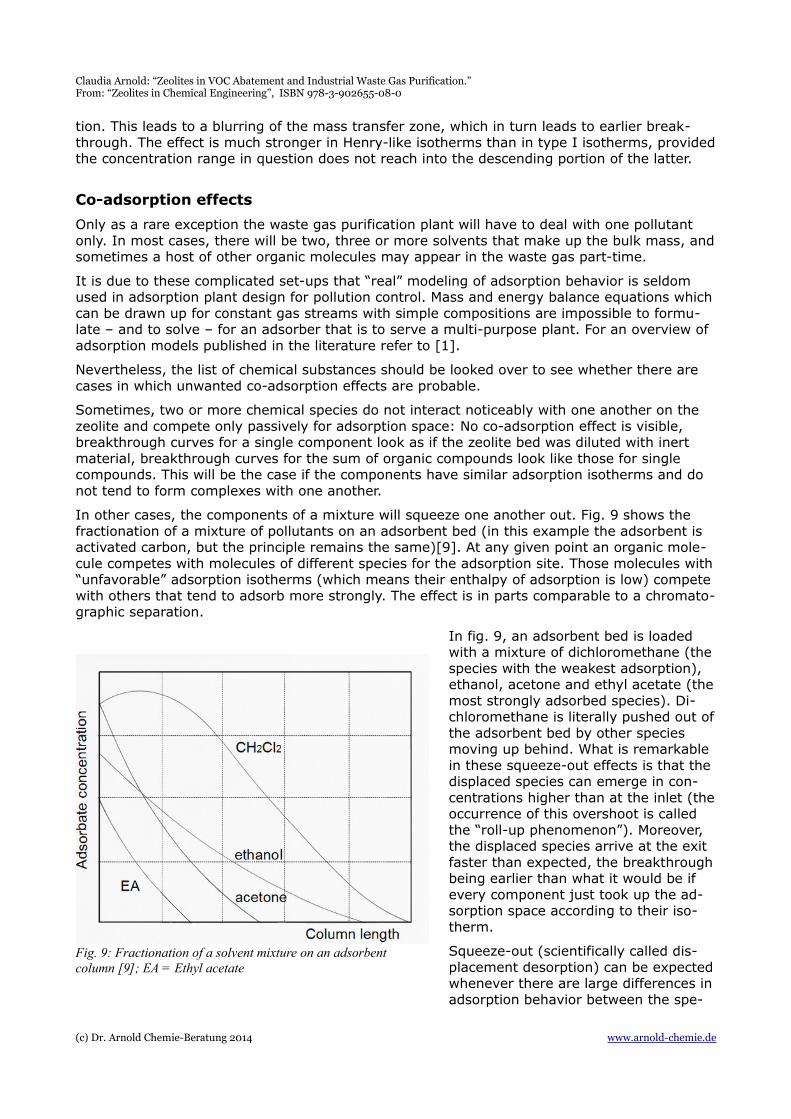
In other cases, the components of a mixture will squeeze one another out. Fig. 9 shows the fractionation of a mixture of pollutants on an adsorbent bed (in this example the adsorbent is activated carbon, but the principle remains the same)[9]. At any given point an organic mole-cule competes with molecules of different species for the adsorption site. Those molecules with“unfavorable” adsorption isotherms (which means their enthalpy of adsorption is low) compete with others that tend to adsorb more strongly. The effect is in parts comparable to a chromato-graphic separation.
In fig. 9, an adsorbent bed is loaded with a mixture of dichloromethane (thespecies with the weakest adsorption), ethanol, acetone and ethyl acetate (themost strongly adsorbed species). Di-chloromethane is literally pushed out ofthe adsorbent bed by other species moving up behind. What is remarkable in these squeeze-out effects is that the displaced species can emerge in con-centrations higher than at the inlet (theoccurrence of this overshoot is called the “roll-up phenomenon”). Moreover, the displaced species arrive at the exit faster than expected, the breakthroughbeing earlier than what it would be if every component just took up the ad-sorption space according to their iso-therm.
Squeeze-out (scientifically called dis-placement desorption) can be expectedwhenever there are large differences inadsorption behavior between the spe-
(c) Dr. Arnold Chemie-Beratung 2014 www.arnold-chemie.de
Fig. 9: Fractionation of a solvent mixture on an adsorbent column [9]; EA = Ethyl acetate
Claudia Arnold: “Zeolites in VOC Abatement and Industrial Waste Gas Purification.” From: “Zeolites in Chemical Engineering”, ISBN 978-3-902655-08-0
cies. Roll-up can occur where the displaced component has a (quasi)linear dependency bet-ween concentration and adsorption quantity.
In rare cases co-adsorption of two components leads to an increased adsorption capacity for both. However, this is more of a lab curiosity. For instance, water displaces carbon dioxide froma Ca-A (hydrophilic 5 Å Type A) [10], but in 13X (hydrophilic faujasite), the adsorption capacityfor both components is increased through co-adsorption [11]. What happens is that water and carbon dioxide form a complex for which there is only room enough in the larger pores of the 13 Å zeolite. In the narrower pores of Ca-A the complex cannot form, and the species com-pete.
As a rule, it is not safe to transfer isotherms of single substance adsorption systems to binary, ternary or more complex systems. Not only is every extrapolation unsafe in itself, but the exis-tence of additional species in the system changes the behavior of the adsorbate. While the so-called carrier gas is usually left out in the treatment of adsorption (except as a medium for the transport of energy and mass), there is in fact no such thing as a neutral carrier gas that does not interact with the adsorbent.
What can be done to cope with the effects of co-adsorption? Not much in the case of multi-purpose plants, where almost any combination of solvents can enter the adsorbent bed, meet-ing with any other organic species left there from previous waste gas quantities. One possible solution is to build extra security into the beds, making them deeper, but paying extra with higher prime cost, increased pressure drop and prolonged regeneration times. Another, more energy-efficient, method is to keep additional zeolite beds ready for use as a standby, e. g. three beds instead of two, with two beds in regular use and one for backup.
If regular combinations of VOCs contain mixtures of volatile solvents with Henry-like isothermsand higher boiling organic compounds (that is to say, if methanol, acetone, methylene chlorideor other solvents with similar adsorption behavior are regularly used in larger amounts), roll-up will be encountered regularly. In this case, a larger security has to be designed into the plant. It pays to have dynamic adsorption isotherms with model adsorbers with a diameter of at least 7 – 10 cm measured. They may cost several thousand Euros per run, but this is cheap in comparison with a plant that is designed too large, causing high prime cost and excessive energy consumption. Certainly isotherm measurements are less expensive than a plant that is designed too small, necessitating costly on-site expansions.
Dynamics of the adsorption process
No adsorber that has to comply to emission threshold levels is utilized to its maximal capacity, there is always an unused portion. This LUB (length of unused bed) is determined by the shapeof the mass transfer zone, which in turn is determined by mass transfer velocity.
As was said before for co-adsorption effects, it will rarely be possible to determine the LUB by mathematical models. So, a security of 30 – 40% is added to the quantity determined by ad-sorption capacity calculations.
Conditions that favor mass transfer, reduce longitudinal diffusion and therefore lead to a narrow mass transfer zone are:
• Gas stream superficial velocity that stays within the given limits for a zeolite particle type, the superficial velocity being neither too slow (which leads to laminar flow and a sharp drop in mass transfer rate) nor too fast (which would increase longitudinal diffu-sion and reduce contact time)
• Effective dispersion of the gas stream over the whole abutting face at the column inlet. For this, a layer of corundum or ceramic balls is usually recommended. As a girder, corrugated, perforated metal sheets are suitable. They are better than flat grids, as they fix the beads to their place during thermal expansion, reducing attrition. As an ad-ditional advantage, the area open for gas flow is larger than with flat grids.
(c) Dr. Arnold Chemie-Beratung 2014 www.arnold-chemie.de
Claudia Arnold: “Zeolites in VOC Abatement and Industrial Waste Gas Purification.” From: “Zeolites in Chemical Engineering”, ISBN 978-3-902655-08-0
• Diligent filling of the adsorber. A rough, loose filling might contain channels. Channels lead to early, sometimes instantaneous breakthrough.
• Isothermal conditions. In pollution control, this is normally not a problem, since the waste gas streams are diluted and the heat of adsorption is small.
If possible, concentration peaks should be avoided, as they greatly disturb the established cycle times. What happens when a concentration peak enters the adsorbent bed can be gauged by the adsorption isotherm shape of the component [1]:
• If it is concave, like type III or type V-isotherms, higher concentrations are adsorbed disproportionately better, so that the peak is contained for some time. Waste gas of lower concentration that follows the peak will push the zone of high adsorption through the bed, blurring it.
• If it is has the shape of a type I isotherm, that is, convex with an extended plateau, a zone of high adsorption will extend through the bed almost with the speed of superficialvelocity, until the partial pressure in the gas phase has dropped sufficiently. The ensu-ing waste gas with lower concentration will push the highly laden zone forward if its concentration is so low as to lay in the ascending portion of the isotherm.
How to make laboratory experiments scalable
In many cases, it is best to make laboratory experiments before doing the lay-out of the actualplant. Either because there is no adsorption data at all to be found, or because co-adsorption effects need to be elucidated, or fouling is apprehended. There are mainly three types of ex-periments that can be performed:
• measurement of adsorption and co-adsorption isotherms
• TPD (thermo-programmed desorption spectroscopy)
• dynamic experiments on the bench scale that can be scaled up more or less directly.
The first will cost around 100 € per measurement, or a little more, depending on the laborato-ry, while bench-scale experiments can amount to 2.000 € per experiment, or more, since they require the presence of a lab technician for long times and cannot be fully automated. Iso-therms and TPD are performed on small samples of the zeolite, while a dynamic bench-scale experiment (or sometimes even at pilot plant scale) is performed on an actual column, for which an artificial polluted feed gas has to be generated, and whose effluents are monitored byan FID monitor and frequent gas chromatography runs. While the small scale experiments givedata on equilibrium adsorption behavior, the dynamic experiment also shows the kinetic of the adsorption process, lumping the effects of pressure drop, particle size and shape, temperature,diffusion in the bed and co-adsorption behavior. All in all, it delivers the desired break-through curve, which can be directly transformed to the design of the plant itself.
Laboratory adsorption experiments are useful for determining the equilibrium adsorption be-havior of single components and can tell whether co-adsorption with a given combination is competitive. TPD is essentially a monitoring of the thermal desorption procedure and shows at which temperature desorption, or any other energy-consuming reaction takes place, which could indicate coking. TPD can be combined with other tests on the used sample, like BET sur-face determination or microporosimetry, which give further information on whether pore block-age has occurred. Differential weighing before adsorption and after TPD shows whether there are measurable deposits left on the sample, or whether a decrease in surface is rather due to disruption of the structure or pore blockage.
Dynamic experiments are rarely performed because of their price and the few pilot plants and labs that offer them, but they can be the last resort in complicated situation where all else fails. It should be noted that adsorbent samples of dynamic experiments can also be taken intothe analytical laboratory, e. g. for TPD.
(c) Dr. Arnold Chemie-Beratung 2014 www.arnold-chemie.de
Claudia Arnold: “Zeolites in VOC Abatement and Industrial Waste Gas Purification.” From: “Zeolites in Chemical Engineering”, ISBN 978-3-902655-08-0
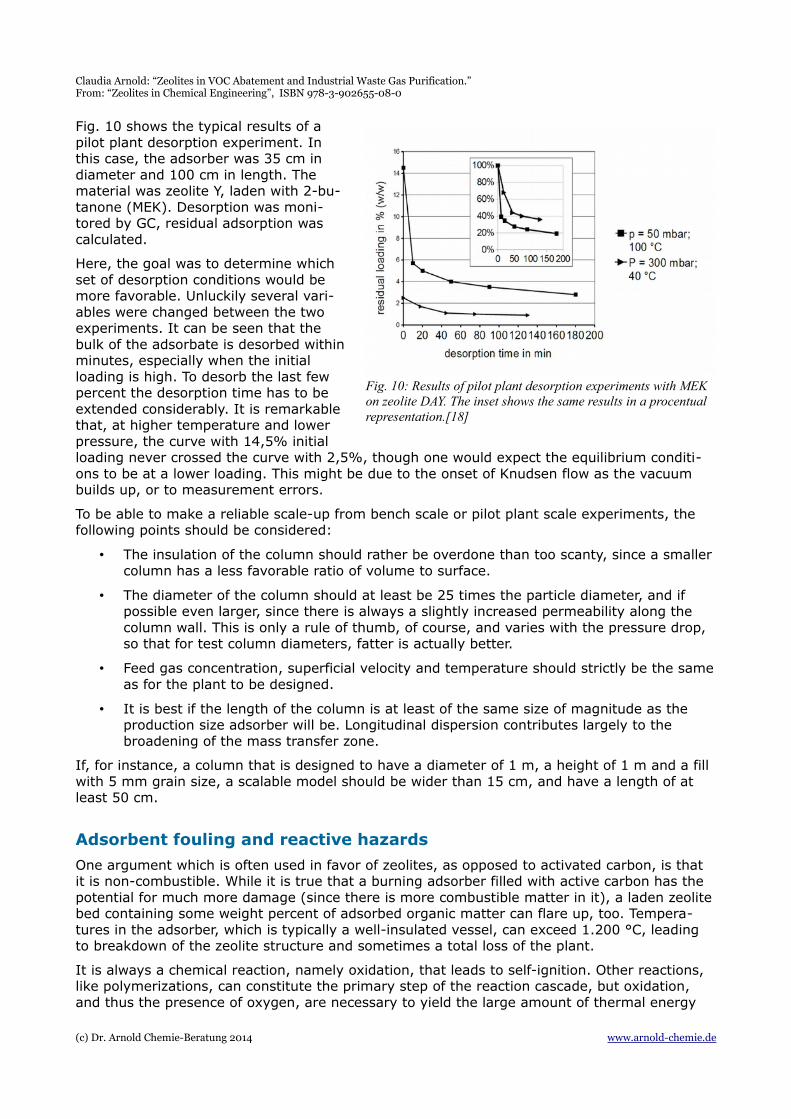
Fig. 10 shows the typical results of apilot plant desorption experiment. Inthis case, the adsorber was 35 cm indiameter and 100 cm in length. Thematerial was zeolite Y, laden with 2-bu-tanone (MEK). Desorption was moni-tored by GC, residual adsorption wascalculated.
Here, the goal was to determine whichset of desorption conditions would bemore favorable. Unluckily several vari-ables were changed between the twoexperiments. It can be seen that thebulk of the adsorbate is desorbed withinminutes, especially when the initialloading is high. To desorb the last fewpercent the desorption time has to beextended considerably. It is remarkablethat, at higher temperature and lowerpressure, the curve with 14,5% initialloading never crossed the curve with 2,5%, though one would expect the equilibrium conditi-ons to be at a lower loading. This might be due to the onset of Knudsen flow as the vacuum builds up, or to measurement errors.
To be able to make a reliable scale-up from bench scale or pilot plant scale experiments, the following points should be considered:
• The insulation of the column should rather be overdone than too scanty, since a smallercolumn has a less favorable ratio of volume to surface.
• The diameter of the column should at least be 25 times the particle diameter, and if possible even larger, since there is always a slightly increased permeability along the column wall. This is only a rule of thumb, of course, and varies with the pressure drop, so that for test column diameters, fatter is actually better.
• Feed gas concentration, superficial velocity and temperature should strictly be the sameas for the plant to be designed.
• It is best if the length of the column is at least of the same size of magnitude as the production size adsorber will be. Longitudinal dispersion contributes largely to the broadening of the mass transfer zone.
If, for instance, a column that is designed to have a diameter of 1 m, a height of 1 m and a fill with 5 mm grain size, a scalable model should be wider than 15 cm, and have a length of at least 50 cm.
Adsorbent fouling and reactive hazards
One argument which is often used in favor of zeolites, as opposed to activated carbon, is that it is non-combustible. While it is true that a burning adsorber filled with active carbon has the potential for much more damage (since there is more combustible matter in it), a laden zeolitebed containing some weight percent of adsorbed organic matter can flare up, too. Tempera-tures in the adsorber, which is typically a well-insulated vessel, can exceed 1.200 °C, leading to breakdown of the zeolite structure and sometimes a total loss of the plant.
It is always a chemical reaction, namely oxidation, that leads to self-ignition. Other reactions, like polymerizations, can constitute the primary step of the reaction cascade, but oxidation, and thus the presence of oxygen, are necessary to yield the large amount of thermal energy
(c) Dr. Arnold Chemie-Beratung 2014 www.arnold-chemie.de
Fig. 10: Results of pilot plant desorption experiments with MEK on zeolite DAY. The inset shows the same results in a procentual representation.[18]
Claudia Arnold: “Zeolites in VOC Abatement and Industrial Waste Gas Purification.” From: “Zeolites in Chemical Engineering”, ISBN 978-3-902655-08-0
needed for a thermal runaway.
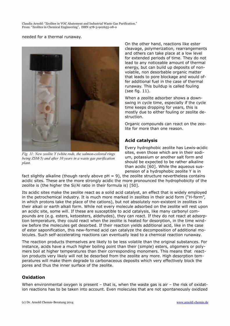
On the other hand, reactions like ester cleavage, polymerization, rearrangementsand others can take place at a low level for extended periods of time. They do not lead to any noticeable amount of thermal energy, but can build up deposits of non-volatile, non desorbable organic matter that leads to pore blockage and would of-fer additional fuel in the case of thermal runaway. This buildup is called fouling (see fig. 11).
When a zeolite adsorber shows a down-swing in cycle time, especially if the cycle time keeps dropping for years, this is mostly due to either fouling or zeolite de-struction.
Organic compounds can react on the zeo-lite for more than one reason.
Acid catalysis
Every hydrophobic zeolite has Lewis-acidicsites, even those which are in their sodi-um, potassium or another salt form and should be expected to be rather alkaline than acidic [60]. While the aqueous sus-pension of a hydrophobic zeolite Y is in
fact slightly alkaline (though rarely above pH = 9), the zeolite structure nevertheless contains acidic sites. These are the more strongly acidic the more pronounced the hydrophobicity of the zeolite is (the higher the Si/Al ratio in their formula is) [50].
Its acidic sites make the zeolite react as a solid acid catalyst, an effect that is widely employed in the petrochemical industry. It is much more marked in zeolites in their acid form (“H-form”, in which protons take the place of the cations), but not absolutely non-existent in zeolites in their alkali or earth alkali form. While not every molecule adsorbed on the zeolite will rest uponan acidic site, some will. If these are susceptible to acid catalysis, like many carbonyl com-pounds are (e.g. esters, ketoesters, aldehydes), they can react. If they do not react at adsorp-tion temperature, they could react when the zeolite is heated for desorption, in the time wind-ow before the molecules get desorbed. If their reaction yields additional acid, like in the case of ester saponification, this new-formed acid can catalyze the decomposition of additional mo-lecules. Such self-accelerating reactions can eventually lead to a chemical reaction runaway.
The reaction products themselves are likely to be less volatile than the original substances. Forinstance, acids have a much higher boiling point than their (simple) esters, oligomers or poly-mers boil at higher temperatures than their corresponding monomers. This means that react-ion products very likely will not be desorbed from the zeolite any more. High desorption tem-peratures will make them degrade to carbonaceous deposits which very effectively block the pores and thus the inner surface of the zeolite.
Oxidation
When environmental oxygen is present – that is, when the waste gas is air – the risk of oxidat-ion reactions has to be taken into account. Even molecules that are not spontaneously oxidized
(c) Dr. Arnold Chemie-Beratung 2014 www.arnold-chemie.de
Fig. 11: New zeolite Y (white rods, the salmon-colored rings being ZSM-5) and after 10 years in a waste gas purification plant.
Claudia Arnold: “Zeolites in VOC Abatement and Industrial Waste Gas Purification.” From: “Zeolites in Chemical Engineering”, ISBN 978-3-902655-08-0
by ambient air can become more susceptible to oxidation in their adsorbed state. Physisorptionmeans that the molecule forms one or several partial bonds towards the zeolite surface, for which it “pays” by a weakening of some other of its own chemical bonds. A weakened chemicalbond is a bond activated for reactions.
At best, oxidation reactions lead to other volatile compounds and not much thermal energy, in which case they might go unnoticed. On the other hand, they can lead to polymeric or other-wise non-volatile compounds, which would lead to fouling. However, the worst case would be athermal runaway of the oxidation reaction that leads to high temperatures in the adsorber – a so-called autoignition of the bed.
Thermal runaway and autoignition
Those general rules of thumb which are formulated to quickly gauge the reactive hazard of chemical reactions are usually designed for reactions in the liquid state [13], they do not applyfor solid beds. While a lot of work has been dedicated to thermal runaways in carbon beds (seefor example [14]), less is being published on behalf of zeolites. Generally speaking, two factorsmust be present for autoignition to occur. These are: exothermic reactions taking place on the
bed, and too low or irregular gas flow.
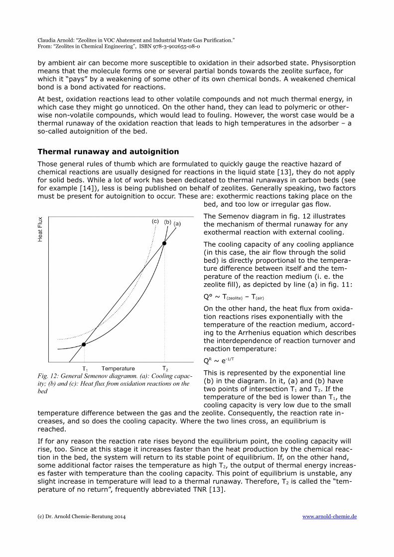
The Semenov diagram in fig. 12 illustrates the mechanism of thermal runaway for any exothermal reaction with external cooling.
The cooling capacity of any cooling appliance (in this case, the air flow through the solid bed) is directly proportional to the tempera-ture difference between itself and the tem-perature of the reaction medium (i. e. the zeolite fill), as depicted by line (a) in fig. 11:
Q° ~ T(zeolite) – T(air)
On the other hand, the heat flux from oxida-tion reactions rises exponentially with the temperature of the reaction medium, accord-ing to the Arrhenius equation which describesthe interdependence of reaction turnover andreaction temperature:
QR ~ e-1/T
This is represented by the exponential line (b) in the diagram. In it, (a) and (b) have two points of intersection T1 and T2. If the temperature of the bed is lower than T1, the cooling capacity is very low due to the small
temperature difference between the gas and the zeolite. Consequently, the reaction rate in-creases, and so does the cooling capacity. Where the two lines cross, an equilibrium is reached.
If for any reason the reaction rate rises beyond the equilibrium point, the cooling capacity will rise, too. Since at this stage it increases faster than the heat production by the chemical reac-tion in the bed, the system will return to its stable point of equilibrium. If, on the other hand, some additional factor raises the temperature as high T2, the output of thermal energy increas-es faster with temperature than the cooling capacity. This point of equilibrium is unstable, any slight increase in temperature will lead to a thermal runaway. Therefore, T2 is called the “tem-perature of no return”, frequently abbreviated TNR [13].
(c) Dr. Arnold Chemie-Beratung 2014 www.arnold-chemie.de
Fig. 12: General Semenov diagramm. (a): Cooling capac-ity; (b) and (c): Heat flux from oxidation reactions on the bed
Claudia Arnold: “Zeolites in VOC Abatement and Industrial Waste Gas Purification.” From: “Zeolites in Chemical Engineering”, ISBN 978-3-902655-08-0
All this is valid for constant concentrations of the reactants in the bed. However, accidental oxi-dation reactions do not start evenly distributed all over the bed, but rather in small, local nests. These so-called “hot-spots” can form wherever inhomogeneities of the gas flow have given rise to a local build-up of organic substances on the zeolite. If the heat released by the oxidation reaction is not transmitted fully to the surrounding, these hot-spots can slowly in-crease in temperature and then spread, which is tantamount to an increase of the reactant concentration [16] (for a general study of autoignition in bulk goods see [61]). This shifts the curve of QR = f(T) upwards (line (c) in the diagram in fig. 12).
It is now easily visible that when the reactant concentration rises high enough – that is, when the hot-spots spread far enough – there will be only one point of intersection left, and that will be a point of no return.
While it is next to impossible to predict precisely the occurrence of thermal runaways, the ob-servation of some rules makes them at least less probable.
• The most important rule is to never shut down a laden adsorber. This would give any hot spots ample time to develop, using up the residual oxygen in the system, with no cooling to quench their formation. When (e. g. after a weekend close-down) the adsor-ber is reopened and a thermal desorption cycle started, the inflow of additional oxygen can lead to spontaneous autoignition – the case of a typical “Monday fire” [1]. There-fore, any laden adsorber should be desorbed directly as soon as it goes offline. Nor should a partially laden adsorber be left for later use, especially if it would stand still forlonger time.
• Equally important is it to take measures to ensure an even gas flow, with no dead angles in the zeolite fill. This is achieved by a correct design of the bed's inflow and by maintaining a turbulent flow. The flow is turbulent if the pressure drop exceeds 230 Pa/m [15].
• Structural fire prevention includes built-in flame arresters and temperature monitoring. Temperature monitoring should comprise at least two measuring points per adsorber, more being better, since their function is to detect any unusual temperature profiles [14]. If detected early, oxidation reactions can be quenched with little or no damage to the plant. Flame arresters prevent a flame from spreading out of the pipes they block, but of course do not prevent the ignition itself.
Though some classes of organic compounds (especially sulfur compounds with sulfur in low oxidation numbers) have gained a certain notoriety for being especially prone to autoignition, in fact no such tendency is known from the literature.
Heat of adsorption
Can the heat of adsorption be responsible for autoignition? In waste gas purification settings, usually not. While in bulk separators, like in ethanol – water separation, temperatures can rise up to 120 °C [17] and limit the maximum water concentration in the feed, the VOC concentrat-ions in waste gas purification plants are usually rather low and the gas flow is maximized, so that the temperature in the adsorption zone does not rise more than a few degrees centigrade.
Adsorption enthalpy data are not easy to come by, but for a first assesment of the thermal energy to be expected, the condensation enthalpy of the compound can be used, as they are usually within the same range of magnitude [19].
For an exemplary calculation the following data shall be used:
Heat capacity of the zeolite: Cp(Zeolite) = 0,92 kJ/(kg * K) [15]
Feed concentration of ethanol: C = 5 g/m³
Adsorption capacity under the given conditions: θ ≈ 5 g/100 g zeolite Y [6]
(c) Dr. Arnold Chemie-Beratung 2014 www.arnold-chemie.de
Claudia Arnold: “Zeolites in VOC Abatement and Industrial Waste Gas Purification.” From: “Zeolites in Chemical Engineering”, ISBN 978-3-902655-08-0
Condensation enthalpy of ethanol: ΔHv = 0,93 kJ/g [20]
Heat capacity of air under the conditions in the adsorber : Cp(air) ≈ 1,3 kJ/m³*K [20]
On the assumption that the generated thermal energy is evenly distributed between air and zeolite, it follows that the temperature rise is
ΔT = (C * ΔHv)/(Cp(air) * mair + Cp(Zeolite) * m(zeolite))
Inserting the given figures results in a temperature increase of 2,6 K for the zeolite bed and the air at maximum. This is only an order of magnitude, since superficial velocity and other factors will also influence the generation and distribution of thermal energy, but it shows that itis not the adsorption enthalpy that leads to a critical rise of temperature, but that unwanted chemical reactions, mainly oxidation reactions, are the real culprits.
… during peak concentrations
What about peak concentrations, would they yield sufficient enthalpy to cause thermal run-away?
At 20 °C, the saturation concentration of ethanol is 112 g/m³, the adsorption capacity of the zeolite at this concentration and temperature is approaching 16 g/100g (more exact figures not being available). The same calculation as above yields a temperature increase of roughly 53 K if the thermal energy was dispersed equally between the 1 m³ of air and the 0,7 kg of zeolite necessary to adsorb the ethanol.
Naturally the adsorbate and therefore the thermal energy will be spread out over a wider part of the bed, but this approximate calculation shows that concentration peaks do indeed cause significant thermal effects.
Desorption
In contrast to most activated carbon adsorbers, zeolite-filled adsorbers are almost always re-generated in situ. This necessitates a desorption periphery and consumes energy – the largest part of energy consumption of a zeolite plant goes into desorption, unless waste heat at an ap-propriate level is available (e. g. from a subsequent combustion of the VOCs). On the other hand, the adsorbent remains in place for many years, reducing the cost for disposal and ex-change. While a zeolite plant has a much higher primary cost than an activated carbon adsor-ber, its life cycle costs are lower if the plant stays in operation for two to six years (this de-pends largely on the amount of VOC to be adsorbed).
Desorption must be performed by shifting the thermodynamic conditions of the zeolite to a point where the adsorption is lower. This is mostly done by increasing the temperature of the bed (TSA = temperature swing adsorption), but can also be done by reducing the partial pres-sure of the adsorbate (called PSA – pressure swing adsorption – if done by lowering the overallpressure). A combination of both is also possible.
Mostly rather simple, idealized models are used to determine the regeneration conditions. The reality is more complicated, though. See for example [56] for the effect of additional paramet-ers on PSA performance, [57] for a detailed discussion of various desorption methods includinginert and displacement purge or chromatographic cycles.
The difference between the two loadings of the zeolite – at breakthrough point and after deso-rption is finished – is called the working capacity of the adsorber. It is usually much smaller than the actual adsorption capacity of the zeolite, since desorption is never pushed to the pointof an absolutely clean adsorbent. This would consume too much energy. During plant design, acompromise between working capacity and energy consumption has to be found [2].
Like with activated carbon, desorption by displacement with water vapor is also possible [51], but is not used much.
(c) Dr. Arnold Chemie-Beratung 2014 www.arnold-chemie.de
Claudia Arnold: “Zeolites in VOC Abatement and Industrial Waste Gas Purification.” From: “Zeolites in Chemical Engineering”, ISBN 978-3-902655-08-0
Solvent recovery
In many cases, the adsorber is used chiefly as a concentrator for a VOC oxidation unit, e. g. a catalytic combustion. While the desorbed solvents can be recovered, there are some factors which interfere with an economical reuse of the regenerate:
• The mixture obtained can be useless as such, and/or impossible to redistill adequately.
• The quality requirements for the solvent can be such as to prohibit the use of the re-generate in the production.
• There is no refrigerating plant on site.
• The concentrations in the desorbate are so low that condensation becomes inefficient.
• There is use for the waste heat generated by incineration.
Then again, if combustion becomes impractical, as it is with halogenated solvents, if only one solvent is used, if it is of value in the production process, solvent regeneration should be con-sidered. If the solvent is to be reused, a PSA (pressure swing adsorption) should be employed to save energy on the subsequent cooling step [55], and to minimize decomposition products in the regenerate.
The refrigeration process will consist of two steps, one around 1 °C to get the moisture out, and one at lower temperatures to condense the bulk of the solvent. The temperature of the second cooling step has to be calculated from the physical properties of the solvent. Rarely willthe resulting gas stream be clean enough to be sent to the stack directly, but will have to be looped into the adsorption plant. The solvent still contains some water and decomposition products and will have to be redistilled.
Outlook
Since the first hydrophobic zeolites appeared on the market in the early 1990s, the scope of adsorption technology has changed significantly. While some solvents, like carbon tetrachlor-ide, have more or less disappeared, other molecules, e. g. carbon dioxide [62], have become the new targets.
New materials are needed to target more demanding adsorption tasks. The current reseach leans heavily towards mesoporous materials [63] [64], which tend to have better mass transport properties that microporous zeolites. They can be zeolite-like in composition like the MCM material class [65] or derived from microporous zeolites by post-synthesis treatment [66]. While these materials have much higher maximal adsorption capacities for VOC than the “classic” Na-Y, the adsorption at typical waste gas concentrations is much lower than with zeo-lites [12]. They are not yet on the market in bulk quantities.
On the other side, there are attempts to reduce costs by utilizing the much cheaper natural zeolites for waste gas purification [67], as yet not very successful due to the varying composit-ion and comparatively low purity of these materials.
While research is very active, it is to be expected that well-established materials like Na-Y will reign the field of industrial adsorptive waste gas purification for the next years to come.
1. Bathen, D. and M. Breitbach (2001). Adsorptionstechnik, Springer Verlag Heidelberg.
2. Knaebel, K. S., "How To" Guide for Adsorber Design. Whitepaper, Adsorption Research, Inc., Dublin, Ohio 43016, http://www.research.umbc.edu/~dfrey1/ench445/Adsor-berDes2.pdf
(c) Dr. Arnold Chemie-Beratung 2014 www.arnold-chemie.de
Claudia Arnold: “Zeolites in VOC Abatement and Industrial Waste Gas Purification.” From: “Zeolites in Chemical Engineering”, ISBN 978-3-902655-08-0
3. Savitz, S., F. R. Siperstein, et al. (1999). "Adsorption of Hydrofluorocarbons HFC-134 and HFC-134A on X and Y Zeolites: Effect of Ion-Exchange on Selectivity and Heat of Adsorption." J. Phys. Chem. B 103(39): 8283-8289.
4. Lin, S. H. L., Ruey C., Adsorption of 1,1,1,2-tetrafluoroethane by various adsorbents. Journal of Environmental Engineering 1999, 125 (11), 1048-1053.
5. Calleja, G.; Jimenez, A.; Pau, J.; Dominguez, L.; Perez, P., Multicomponent adsorption equilibrium of ethylene, propane, propylene and CO"2 on 13X zeolite. Gas Separation and Purification 1994, 8 (4), 247-256.
6. Data given by Zeochem AG, 2001
7. Data: UOP GmbH, Grace, Zeochem AG. Data are a compilation from several manufac-turer's sources and can therefore only give an idea.
8. Meininghaus, C. K. W. Hydrophobe Zeolithe zur selektiven Sorption von flüchtigen or-ganischen Lösungsmitteldämpfen. ETH Zürich, Zürich, 1998.
9. Rafflenbeul, R., Fortschritte in der Adsorptionstechnologie. Chemie Ingenieur Technik 1996, 68 (11), 1413-1423.
10.Giacobbe, F. W., Adsorption of very low level carbon dioxide impurities in oxygen on a 13X molecular sieve. Gas Separation and Purification 1991, 5 (1), 16.
11.Rege, S. U.; Yang, R. T., A novel FTIR method for studying mixed gas adsorption at low concentrations: H2O and CO2 on NaX zeolite and γ-alumina. Chemical Engineering Sci-ence 2001, 56 (12), 3781-3796.
12.Zhao, X. S.; Ma, Q.; Lu, G. Q., VOC Removal: Comparison of MCM-41 with Hydrophobic Zeolites and Activated Carbon. Energy Fuels 1998, 12, 1051-1054.
13.See for example “Thermische Sicherheit chemischer Prozesse”, Merkblatt R 004, BG Chemie, 2002.
14.Hofelich, T. C.; LaBarge, M. S.; Drott, D. A., Prevention of thermal runaways in carbon beds. Journal of Loss Prevention in the Process Industries 1999, 12, 517-523.
15.Data given by Zeochem AG, 2009.
16.Krause, U.; Schmidt, M.; Lohrer, C. in “Computations on the coupled heat and mass transfer during fires in bulk materials, coal deposits and waste dumps.” COMSOL Multi-physics User's Conference, Frankfurt, Federal Institute for Materials Research and Test-ing (BAM), D. I. R. S. a. S., Ed. Frankfurt, 2005.
17.Ben-Shebil, S. M., Effect of heat of adsorption on the adsorptive drying of solvents at equilibrium in a packed bed of zeolite. Chemical Engineering Journal 74(3), 197-204.
18.Data were measured in 1995 during an actual project and are reproduced with permis-sion from Omega Technology GmbH (Wilhelmshaven).
19. IUPAC 2001, “Chemisorption and Physisorption”, report available online under http://old.iupac.org/reports/2001/colloid_2001/manual_of_s_and_t/node16.html
20.D. R. Lide (editor), CRC Handbook of Chemistry and Physics, 76th Ed. 1996, CRC Press Boca Raton.
21.Zukal, A., I. Dominguez, et al. (2009). "Functionalization of delaminated zeolite ITQ-6 for the adsorption of carbon dioxide." Langmuir 25(17): 10314-10321.
22.Song, W., G. Li, et al. (2005). "Development of improved materials for environmental applications: nanocrystalline NaY zeolites." Environ Sci Technol 39(5): 1214-1220.
23.Roma, F., J. L. Riccardo, et al. (2005). "Statistical thermodynamics models for poly-atomic adsorbates: application to adsorption of n-paraffins in 5A zeolite." Langmuir
(c) Dr. Arnold Chemie-Beratung 2014 www.arnold-chemie.de
Claudia Arnold: “Zeolites in VOC Abatement and Industrial Waste Gas Purification.” From: “Zeolites in Chemical Engineering”, ISBN 978-3-902655-08-0
21(6): 2454-2459.
24.Song, W., R. E. Justice, et al. (2004). "Synthesis, characterization, and adsorption prop-erties of nanocrystalline ZSM-5." Langmuir 20(19): 8301-8306.
25.El Brihi, T., J. N. Jaubert, et al. (2003). "VOCs isotherms on day zeolite by static and dynamic methods: experiments and modelling." Environ Technol 24(10): 1201-1210.
26.Dutour, S., J. Nokerman, et al. (2004). "Simultaneous determination of mass and calori-metric adsorption data of volatile organic compounds on microporous media in the low relative pressure range." Meas. Sci. Technol. 15: 185-194.
27.Takahashi, A. and R. T. Yang (2002). "New adsorbents for purification: Selective re-moval of aromatics." AiChE Journal 48(7): 1457-1468.
28.Singh, S., H. Tezel, et al. (2002). "Adsorption of tetrafluoromethan and nitrogen by various adsorbents." Separation Science and Technolgy 37(12): 2763-2784.
29.Zhao, X. S., Q. Ma, et al. (1998). "VOC Removal: Comparison of MCM-41 with Hy-drophobic Zeolites and Activated Carbon." Energy Fuels 12: 1051-1054.
30.Garcia-Perez, E., D. Dubbeldam, et al. (2006). "Influence of cation Na/Ca ratio on ad-sorption in LTA 5A: a systematic molecular simulation study of alkane chain length." J Phys Chem B Condens Matter Mater Surf Interfaces Biophys 110(47): 23968-23976.
31. Ju, S. G., Y. P. Zeng, et al. (2006). "Computer simulation of the adsorption of thiophene in all-silica y and na-y." Langmuir 22(20): 8353-8358.
32. Liu, B. and B. Smit (2006). "Molecular simulation of adsorption of alkanes in sodium MOR-type zeolites using a new force field." Phys Chem Chem Phys 8(15): 1852-1857.
33.Ahunbay, M. G. (2007). "Molecular simulation of adsorption and diffusion of chlorinated alkenes in ZSM-5 zeolites." J Chem Phys 127(4): 044707.
34.Elizalde-Gonzalez, M. P. and M. A. Perez-Cruz (2007). "Interaction between organic vapors and clinoptilolite-mordenite rich tuffs in parent, decationized, and lead ex-changed forms." J Colloid Interface Sci 312(2): 317-325.
35.Diaz, E., S. Ordonez, et al. (2005). "Comparative study on the gas-phase adsorption of hexane over zeolites by calorimetry and inverse gas chromatography." J Chromatogr A 1095(1-2): 131-137.
36.Song, W., R. E. Justice, et al. (2004). "Size-dependent properties of nanocrystalline sili-calite synthesized with systematically varied crystal sizes." Langmuir 20(11): 4696-4702.
37.Palomino, M., A. Corma, et al. (2009). "New Insights on CO(2)-Methane Separation Using LTA Zeolites with Different Si/Al Ratios and a First Comparison with MOFs." Lang-muir.
38.Tao, W.-H., T. Yang, et al. (2007). "Effect of Moisture on the Adsorption of Volatile Or-ganic Compounds by Zeolite 13X." Journal of Environmental Engineering 130(10): 1210-1216.
39.Hercigonja, R., V. Dondur, et al. (2005). "A study of the adsorption thermodynamics of n-hexane on ion-exchanged X zeolites." J Serb Chem Soc 70(12): 1409-1418.
40.Schachtl, M. and A. Mersmann (1988). Adsorption und Desorption im adiabaten und isothermen Festbett Reaktionstechnik und Stoffaustauschtechnik in dispersen Zweiphasensystemen. DECHEMA. 114: 175-191, 110f, 111.
41.Wu, C.-Y., T.-W. Chung, et al. (2006). "Dynamic determination of the concentration of volatile alcohols in a fixed bed of zeolite 13X by FT-IR." J Hazard Mater 137(2): 893-898.
(c) Dr. Arnold Chemie-Beratung 2014 www.arnold-chemie.de
Claudia Arnold: “Zeolites in VOC Abatement and Industrial Waste Gas Purification.” From: “Zeolites in Chemical Engineering”, ISBN 978-3-902655-08-0
42.Barthos, R., A. Szechenyi, et al. (2006). "Decomposition and aromatization of ethanol on ZSM-based catalysts." J Phys Chem B Condens Matter Mater Surf Interfaces Biophys 110(43): 21816-21825.
43.Aittomaki, A. and M. Harkonen (1986). "Zeolite heat pump - adsorption of methanol in synthetic zeolites 13X, 4A and 5A." International Journal of Refrigeration 9(4): 240-244.
44.Plant, D. F., A. Simperler, et al. (2006). "Adsorption of methanol on zeolites X and Y. An atomistic and quantum chemical study." J Phys Chem B Condens Matter Mater Surf In-terfaces Biophys 110(12): 6170-6178.
45.Ng, Y. L., R. Yan, et al. (2004). "Volatile organic compound adsorption in a gas-solid flu-idized bed." Water Sci Technol 50(4): 233-240.
46.Noack, M., A. Dittmar, et al. (2007). "Thermische Regenerierung von Zeolithpulver Typ X aus der VOC-Luftreinigung." Chemie Ingenieur Technik 79(6): 883-889.
47.El Brihi, T., J. N. Jaubert, et al. (2003). "VOCs isotherms on day zeolite by static and dynamic methods: experiments and modelling." Environ Technol 24(10): 1201-1210.
48.Ghoshal, S. D. M. A. K. (2006). "Comparison of Adsorption of Ethyl Acetate on ActivatedCarbon and Molecular Sieves 5A and 13X." J. Chem. Eng. Data 51(4): 1185-1189.
49.Khan, F. I. and A. Kr. Ghoshal (2000). "Removal of Volatile Organic Compounds from polluted air." Journal of Loss Prevention in the Process Industries 13(6): 527.
50. Mota, C. J. A., D. L. Bhering, et al. (2004). "A DFT Study of the Acidity of Ultrastable Y Zeolite: Where is the Bronstedt/Lewis Acid Synergism?" Angew Chem 116: 3112-3115.
51. J. Küntzel, R. H., Th. Melin, (1999). "Regeneration of Hydrophobic Zeolites with Steam."Chemical Engineering & Technology 22(12): 991-994.
52. “Effects of Contaminants on Molecular Sieves”, Technical Application/Information Bul-letin by GRACE Davison
53.R. E. Trent, “Fundamentals of Molecular Sieve Design”, presented at the American Insti-tute of Chemical Engineers Spring National Meeting. Houston, Texas, 1992. Published asa brochure by Zeochem AG.
54.Takeuchi, Y., H. lwamoto, et al. (1995). "Adsorption of 1-butanol and p-xylene vapor and their mixtures with high silica zeolites." Separations Technology 5(1): 23-34.
55.EPA Technical Bulletin No. 456/F-99-004 (1999)
56. “Pressure Swing Adsorption−Solvent Vapor Recovery: Process Dynamics and ParametricStudy.” Yujun Liu and, James A. Ritter, Industrial & Engineering Chemistry Research 1996, 35 (7), 2299-2312
57. “Gas-Adsorption Processes: State of the Art”. Keller, G. E., Industrial Gas Separations. 1983, 145-169
58. “Determining Volatile Organic Compounds' Adsorption Isotherms on Dealuminated Y Zeolite and Correlation with Different Models.” El Brihi, T.; Jaubert, J.-N.; Barth, D; Perrin, L. Journal of Chemical & Engineering Data 2002 47 (6), 1553-1557
59. “Adsorption Equilibria of Water Vapor on Activated Carbon and DAY Zeolite.” Min-Bae Kim, Young-Ki Ryu, Chang-Ha Lee, Journal of Chemical & Engineering Data 2005, 50 (3), 951-955.
60.Wu, X. (2004). Acidity and catalytic activity of zeolite catalysts bound with silica and alumina.
61.Krause, U., M. Schmidt, et al. (2005). “Computations on the coupled heat and mass transfer during fires in bulk materials, coal deposits and waste dumps.” COMSOL Multi-
(c) Dr. Arnold Chemie-Beratung 2014 www.arnold-chemie.de
Claudia Arnold: “Zeolites in VOC Abatement and Industrial Waste Gas Purification.” From: “Zeolites in Chemical Engineering”, ISBN 978-3-902655-08-0
physics User's Conference, Frankfurt.
62. “Comparison of Activated Carbon and Zeolite 13X for CO2 Recovery from Flue Gas by Pressure Swing Adsorption.” K. T. Chue, J. N. Kim, Y. J. Yoo, S. H. Cho, R. T. Yang, In-dustrial & Engineering Chemistry Research 1995 34 (2), 591-598
63.Ciambelli, P. and D. Sannino (2007). Special issue : comparing zeolites and novel micro and mesoporous materials, Springer.
64.Galarneau, A. (2001). Zeolites and mesoporous materials at the dawn of the 21st cen-tury : proceedings of the 13th International Zeolite Conference, Montpellier, France, 8-13 July 2001. Amsterdam ; London, Elsevier.
65.Weber, A. (2003). Synthese, Charakterisierung und katalytische Eigenschaften von Ze-olithen mit ungewöhnlicher Porenarchitektur. Fachbereich Chemie. Kaiserslautern, Tech-nischen Universität Kaiserslautern. Dr rer nat: 181.
66. Janssen, A. H., A. J. Koster, et al. (2002). "On the Shape of the Mesopores in Zeolite Y: A Three-Dimensional Transmission Electron Microscopy Study Combined with Texture Analysis." J Phys Chem B 106: 11905-11909.
67.Ackley, M. W., S. U. Rege, et al. (2003). "Application of natural zeolites in the purifica-tion and separation of gases." Microporous and Mesoporous Materials 61(1-3): 25-42.
(c) Dr. Arnold Chemie-Beratung 2014 www.arnold-chemie.de