zero setting psb protection_cbip
TRANSCRIPT

ZERO SETTING POWER SWING BLOCKING PROTECTION
BY - JYOTIRMOY
CHANDRAKANTH
SURJIT
BADAL

DEFINITION : POWER SWING
A power swing is a system phenomenon that is observed when the phase angle of one power source starts to vary in time with respect to another source on the same network
A power swing is stable when, following a disturbance, the rotation speed of all machines returns to synchronous speed
A power swing is unstable when, following a disturbance, one or more machines do not return to synchronous speed. The generator torque angle reaches 180 degrees, the machine is said to have slipped a pole, reached an out-of-step(OOS) condition, or lost synchronism.
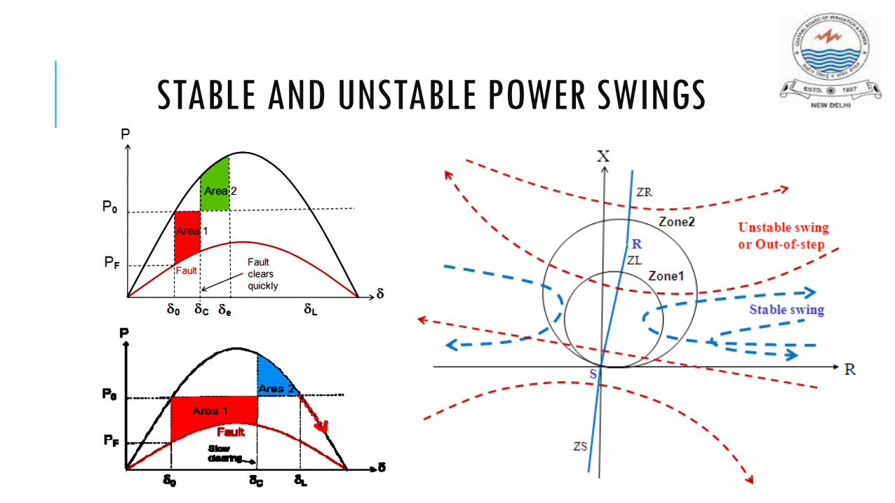
STABLE AND UNSTABLE POWER SWINGS
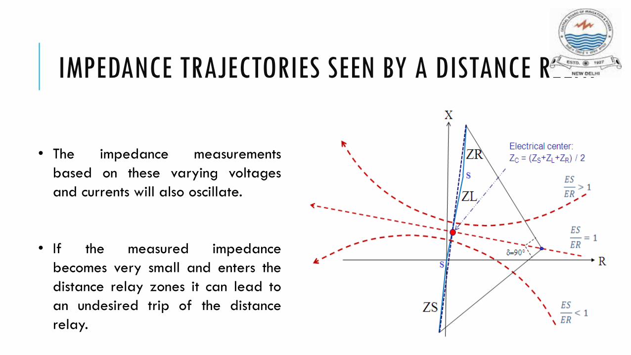
IMPEDANCE TRAJECTORIES SEEN BY A DISTANCE RELAY
• The impedance measurements
based on these varying voltages
and currents will also oscillate.
• If the measured impedance
becomes very small and enters the
distance relay zones it can lead to
an undesired trip of the distance
relay.

IMPEDANCE TRAJECTORIES FOR VARIOUS RATIOS OF |ES/ER|

JUSTIFICATION FOR POWER SWING DETECTION
PSB signal ensures security of relay elements that are prone to operate during power swings
OST signal separates power system at predetermined locations to avoid network collapse during unstable power swings
CONVENTIONAL POWER SWING DETECTION METHODS
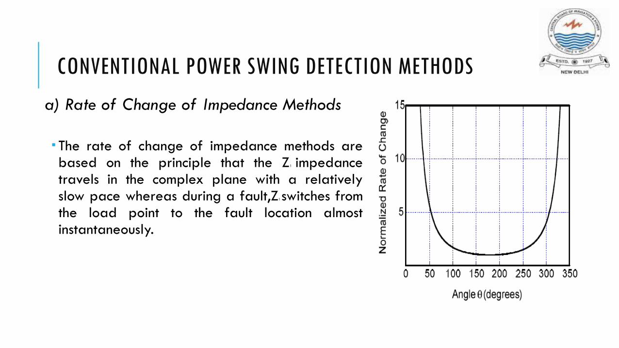
a) Rate of Change of Impedance Methods
The rate of change of impedance methods arebased on the principle that the Z1 impedancetravels in the complex plane with a relativelyslow pace whereas during a fault,Z1switches fromthe load point to the fault location almostinstantaneously.

RATE OF CHANGE OF IMPEDANCE METHODS
Blinder Scheme
Single Blinder : detects an unstable power swing when the time interval required to cross the distance between the right and left blinders exceeds a minimum time setting
Double Blinder : During a power swing, the single-blinder element measures the time interval ∆T that it takes the Z1 trajectory to cross the distance between the outer and inner blinders. When this measured time interval is longer than a set time delay, a power swing is declared.

CONVENTIONAL POWER SWING DETECTION METHODS
b) Concentric Characteristic Schemes
Principle:
After an outer characteristic has been crossed bythe Z1 impedance, a timer is started and theinterval of time before the inner characteristic isreached is measured. A power swing is detectedwhen the time interval is longer than a set timedelay.


NON-TRADITIONAL METHODS FOR DETECTING POWER SWINGS
Continuous superimposed ΔI
The superimposed current method compares the present values of currents with a buffer that is taken two cycles earlier.
A delta current ΔI is detected if the difference is greater than 5% of the nominal current. A continuous ΔI measurement for three cycles indicates a power swing condition and asserts PSB
Can detect very fast power swings that are hard to detect with conventional schemes especially for heavy load conditions. On the other hand, very slow slip rates below 0.1Hz, where the ΔI between two cycles is less than the threshold of 5% nominal current, are hard to detect with the ΔI method

NON-TRADITIONAL METHODS FOR DETECTING POWER SWINGS
Continuous Impedance Calculation
Monitors the progression in the complex plane
Power swing is declared when the criteria for all three loop impedances have been fulfilled: continuity, monotony, and smoothness.
Continuity verifies that the trajectory is not motionless
Monotony verifies that the trajectory does not change direction
smoothness verifies that there are no abrupt changes in the trajectory

SWING CENTRE VOLTAGE METHOD
SCV is defined as the voltage at the location of a two source equivalent system where the voltage value is zero when the angles between the two sources are 180 degrees apart.
Voltage Phasor Diagram of a Two-Machine System

FEATURES OF SCV
Under normal load conditions, the magnitude of the SCV is constant.
Magnitude of the SCV changes between 0 and 1 p.u of system nominal voltage
SCV during an OOS condition
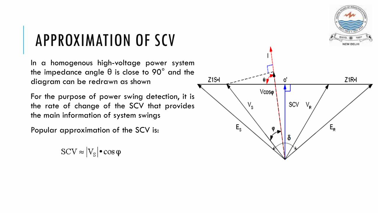
APPROXIMATION OF SCVIn a homogenous high-voltage power systemthe impedance angle θ is close to 90° and thediagram can be redrawn as shown
For the purpose of power swing detection, it isthe rate of change of the SCV that providesthe main information of system swings
Popular approximation of the SCV is:
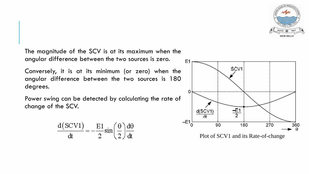
The magnitude of the SCV is at its maximum when theangular difference between the two sources is zero.
Conversely, it is at its minimum (or zero) when theangular difference between the two sources is 180degrees.
Power swing can be detected by calculating the rate ofchange of the SCV.
Plot of SCV1 and its Rate-of-change

BASIC POWER-SWING BLOCKING LOGIC FUNCTION

DEPENDABLE POWER-SWING BLOCKING FUNCTION
The purpose of the dependable power-swing detector is to supply a temporary DPSB signal that will assert the PSB bit to compensate for the pickup delay of the slope detector.
This will happen particularly after a lasting external fault has been cleared and the network embarks into a power-swing situation.
Eg: long-lasting fault right behind or at the remote end of a transmission line on a marginally stable network

SCV1 SLOPE DETECTOR FUNCTION
Rate of change of SCV1 must be above a minimumthreshold (Min_dSCV1)
The magnitude of the SCV1 must be within amaximum (Thr_Hi) and a minimum (Thr_Low) threshold
The positive-sequence impedance measured by thedistance relay must reside within a starter zone.
Output of the slope detector is blocked any timeSCV1 is above a Max_dSCV1) or the absolute valueof the discontinuity detector is above Thr_d2SCV1.

PRINCIPLE OF SWING-CENTER VOLTAGE DERIVATIVES
Used by the slope detector and swingsignature detector logic functions
Second-order time derivative takes a veryhigh value every time a discontinuity ispresent in the signal
All values of derivatives are computed inper-unit volts per cycle (V (pu)/cycle)

SWING-SIGNATURE DETECTION PRINCIPLE
Complements the slope detector
Based on the fact that if a fault detector picks upduring a power swing, no discontinuity will bepresent on the SCV1 signal prior to the detectionbecause the fault detection is not the result of areal fault
An algorithm that distinguishes between a powerswing and a real fault at the moment the outmostdistance element, to be blocked by the swingdetection, picks up
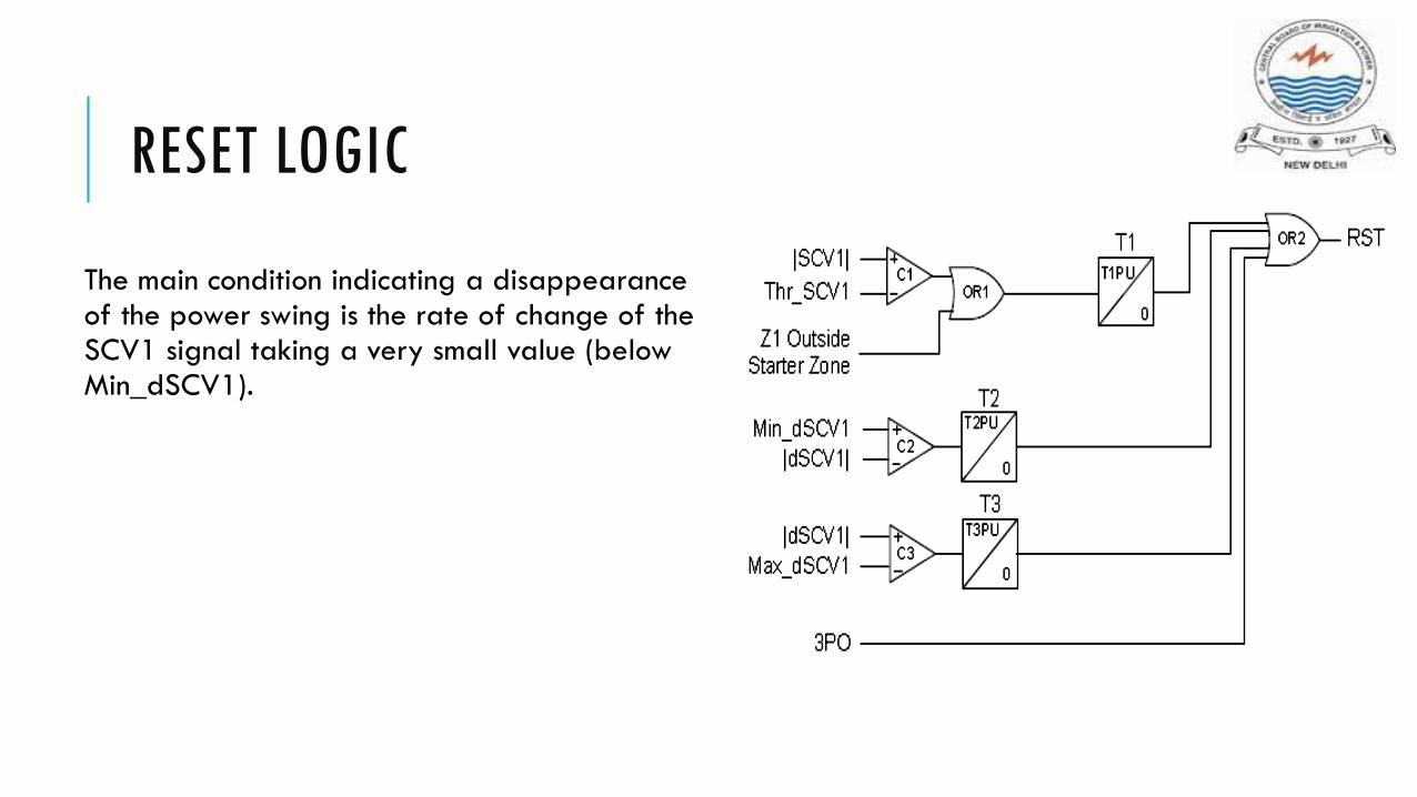
RESET LOGIC
The main condition indicating a disappearance of the power swing is the rate of change of the SCV1 signal taking a very small value (below Min_dSCV1).
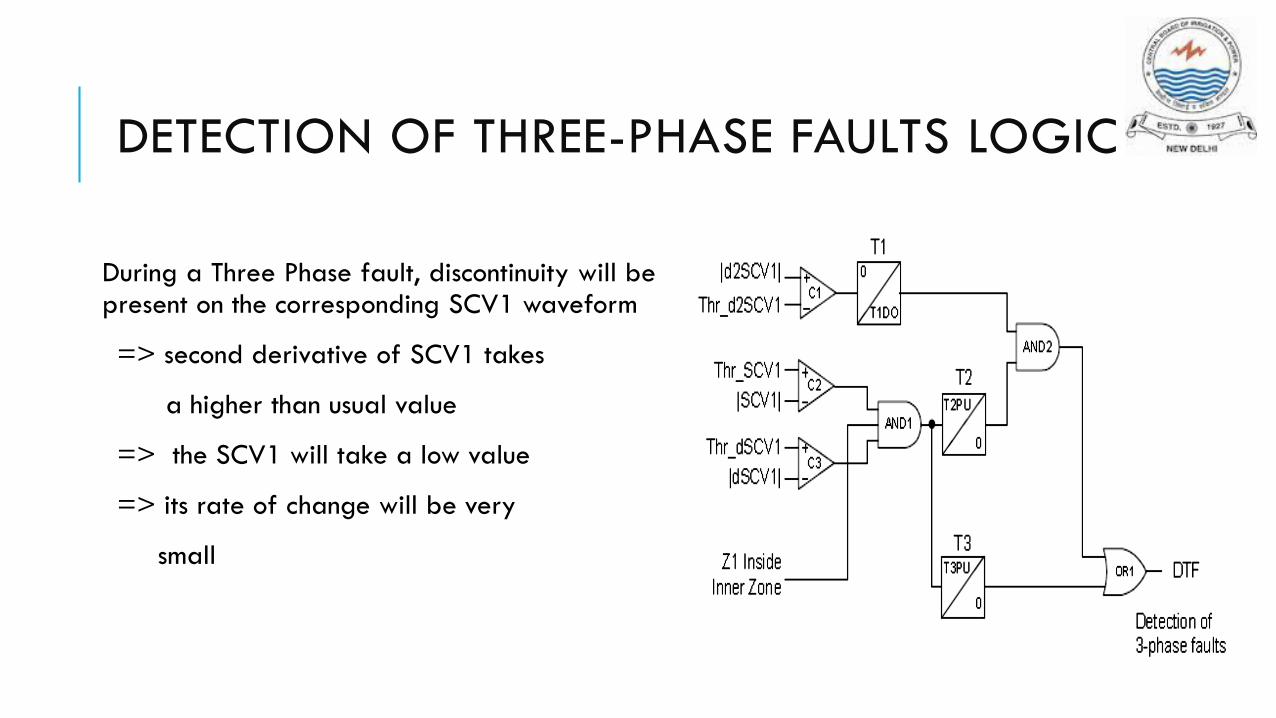
DETECTION OF THREE-PHASE FAULTS LOGIC
During a Three Phase fault, discontinuity will bepresent on the corresponding SCV1 waveform
=> second derivative of SCV1 takes
a higher than usual value
=> the SCV1 will take a low value
=> its rate of change will be very
small
ADVANTAGES OF SCV METHOD
The SCV is independent of the system source and line impedances and is, therefore, particularly attractive for use in a no-setting power-swing blocking function
The SCV is bounded with a lower limit of zero and an upper limit of one per unit, regardless of system impedance parameters.
The magnitude of the SCV relates directly to δ
