zhejiang flashforge 3d technology co., ltd. creator pro...
TRANSCRIPT

www.ff3dp.com
ZHEJIANG FLASHFORGE 3D TECHNOLOGY CO., LTD.
Creator Pro Start-up Guide

www.ff3dp.com
i
Contents 1 What's Included in the Box? 2
2 Un-boxing 2
3 Initial Hardware Installation 5
4 Software Installation 7
5 USB Connection & Temperature Setting 12
6 Filament 16
6.1 Install Filament 16
6.2 Feeding the Filament Using the LCD Screen 17
6.3 Withdrawing the Filament Using LCD Screen 18
6.4 Feeding the Filament Using Replicator G Control Panel 18
6.5 Setting Parameters 19
7 Initial Print 19
8 Dual Extruder Print 22

www.ff3dp.com
1
PRECAUTIONS: Please make sure to read this page carefully prior to setting up and operating the Creator Pro.
The Creator Pro is very sensitive to static electricity, so please make sure you contact a grounded object before operating the machine.
Before repairing or making any alterations to the Creator Pro, it is essential that the machine is turned off and the power cord is unplugged.
The Creator Pro operates at very high temperature; allow the nozzle, the extruded plastic and heating plate to cool before touching.
Some plastic filaments may give off a little odor when heated. Because of this, the machine should always operate in a well-ventilated area.
Do not wear gloves when operating or repairing, as entanglement may occur and cause injury.
Do not leave the machine unattended when in operation.
WARNING Flashforge sets the power supply to default 230v before leaving factory. If voltage in your location is between 90v to 132v, please switch the power setting from 230v to 115v before you plug in the power. Failure to do so will damage the motherboard. You can find the power source at the bottom of Creator Pro. The red box is where the power setting is located:

2
1 What's Included in the Box?
Along with your Creator Pro 3D printer, the box also contains the following: In the two long boxes on the top of the package, you’ll find: • Power cord x 1pc, • USB A to B cable x 1pc, • Sensor Line x 1pc, • Filament guide tube x 2 pcs. • Filament spool holder x 2 pcs. In the Creator Pro Acrylic Accessory box: ● Acrylic sheet x6 pc ● Handle x1 pc ● Accessory bag x1 pcs An accessory box on the top of the Creator Pro: • Dual extruder heads x 1pc, • 4G SD card x 1 pc, • Blue tape x 1 pc, • Bolt, hex wrench and screws kit x 1 bag.
Under Creator Pro’s build platform, there are 2 rolls filament: • White ABS filament x 1kg (2.2pounds), • Blue PLA filament x 1kg (2.2pounds),
2 Un-boxing The Creator Pro was carefully packaged at FLASHFORGE manufacturing facility. Please follow the unboxing steps laid out below.
! First, put the box on the floor in a clean and flat surface. Remove the top two long boxes and set them aside. You will find a power cord, 1 USB A to B cable, 1 sensor line and 2 filament guide tubes in these two long boxes.
CAUTION
Handle the package and its contents with extra care; do not use any unnecessary force.
Do not remove the thin yellow film from the heating plate. It is heat resistant tape that improves the adhesion of the extruded plastic to the plate.
Do not remove the wrapping around the nozzle. It consists of a ceramic fiber fabric and heat resistant tape that helps to keep the nozzle at a constant temperature.
3
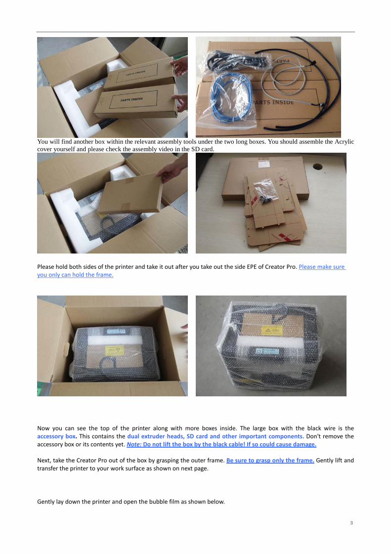
You will find another box within the relevant assembly tools under the two long boxes. You should assemble the Acrylic cover yourself and please check the assembly video in the SD card.
Please hold both sides of the printer and take it out after you take out the side EPE of Creator Pro. Please make sure you only can hold the frame.
Now you can see the top of the printer along with more boxes inside. The large box with the black wire is the accessory box. This contains the dual extruder heads, SD card and other important components. Don't remove the accessory box or its contents yet. Note: Do not lift the box by the black cable! If so could cause damage. Next, take the Creator Pro out of the box by grasping the outer frame. Be sure to grasp only the frame. Gently lift and transfer the printer to your work surface as shown on next page. Gently lay down the printer and open the bubble film as shown below.

4
Now, open the accessory box and remove the accessory sleeve. You will find the dual extruder heads in the protective packaging along with the black cable, carefully remove it and place it on your work surface. Remove the cardboard packing material and take the accessory box from the printer, set it aside for later.
The build platform should now be visible. It is an aluminum plate covered in a thin polyamide film. This is the surface that your objects will be printed on. Note: Remember not remove the film. The next step is to raise the build platform; there are two ways to do this: 1. Turn the screw which is behind the rotating platform. 2. Grasp the printing platform with one hand on each side, raising it slowly and keeping it level.
Stop once the platform is just shy of the bronze nozzle. Now you can see two rolls filaments we offer for free, you can get them easily after removeing the rest packaging.

5
3 Initial Hardware Installation
To do this, begin by carefully placing the Creator Pro on one of its sides so that the bottom is exposed. You will see the Creator Pro’s power supply. Using a flathead screwdriver switch the red power supply switch so that it displays 115v, as shown below. Now you are ready to install the extruder. You'll need two M3*12 screws from the kit found in the accessory box, and the appropriate hex wrench. First, lower the build platform by using one of the methods described in the previous section. Holding the extruder by both sides, take it out of the accessory sleeve and position it on the extruder seat with the fan facing forward. Align the screw holes and fasten with the two short silver screws.
WARNING Flashforge sets the power supply to default 230v before leaving factory. If voltage in your location is between 90v to 132v, please switch the power setting from 230v to 115v before you plug in the power. Failure to do so will damage the motherboard. You can find the power source at the bottom of Creator Pro. The red box is where the power setting is located:

6
Install the side fan duct. To do this, find the side fan duct and attach it onto the left side of the extruder set. Secure it
with the supplied M3x8 screw. Tip: place the M3x12 screw through the mounting hole of the extruder seat first. Afterwards, align the extruder set and tighten.
Next is the installation of the spool holder. Install one on each side. The installation of the spool holder is very simple – just insert it into the circular opening and tighten the nut behind. Then install the filament guide tube to the empty spot on the extruder. Place one end of the guide tube into the hole. The hardware installation is almost complete.
Next, with the power switch in the OFF position, confirm that the power cord is plugged into the power outlet next to the power switch.
Now plug the USB A to B cable into the USB B-type port, do not plug the other end in yet. Finally install the filament on the spool holder.

7
Congratulations! You have completed the initial hardware installation! If you're ready to start printing, proceed to the next step: Software Installation.
4 Software Installation
ReplicatorG0040 is the ideal software to use with the dual extruder Creator Pro. It can be downloaded from our official website by following the link below and click on Download. http://replicat.org/download ReplicatorG0040 for Windows users can also be found in the folder of operational software on the SD card, which shipped together with the Creator Pro. Steps for installing your software:
1. Download the appropriate version of ReplicatorG suitable for your system from http://replicat.org/download.
2. From the SD card shipped with your printer, browse to the “information of 3D printer” folder and run the Python installation file and the Python acceleration components.
SPECIAL NOTES TO WIN 8 USERS BEFORE SOFTWARE INSTALLATION Win 8 users please make sure that you have disabled the Driver Signature Enforcement setting before installing the ReplicatorG software. Below is a video link showing you how to accomplish this: http://www.youtube.com/watch?v=NM1MN8QZhnk
8
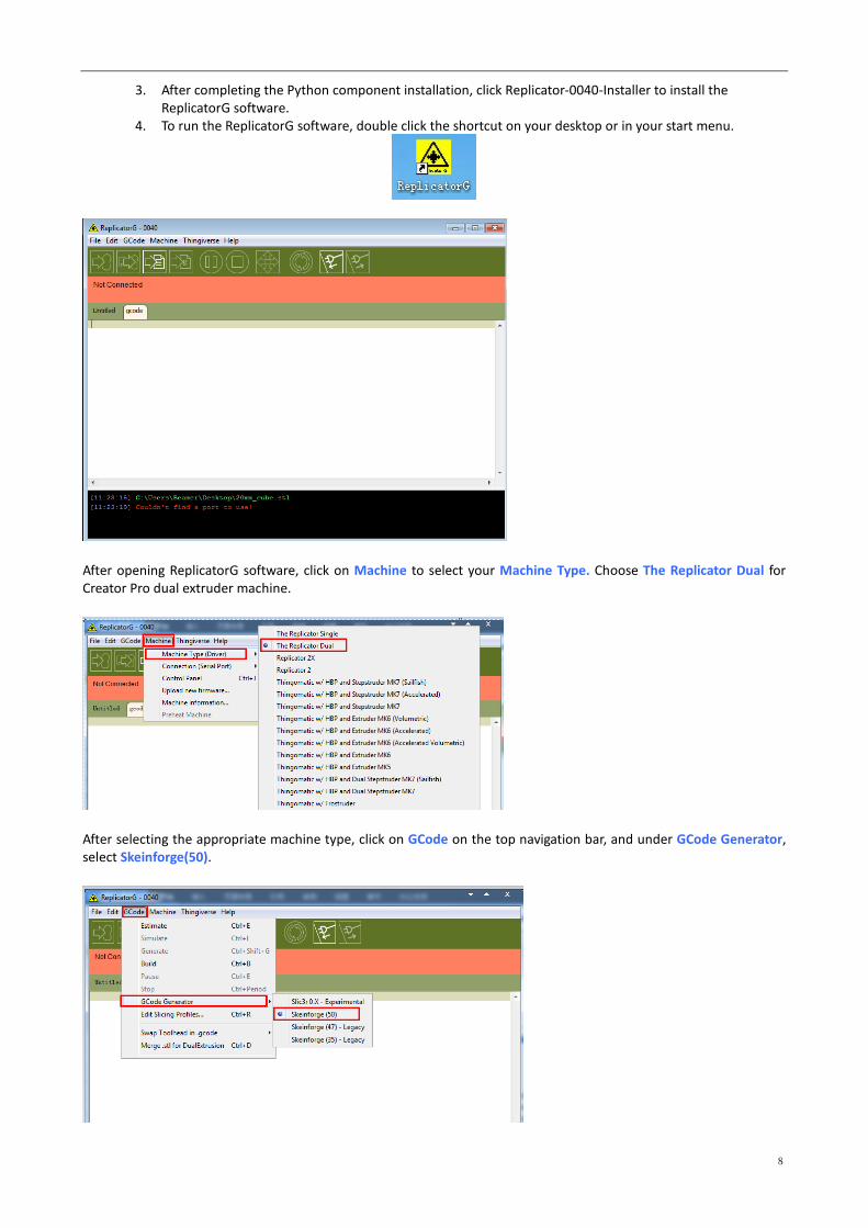
3. After completing the Python component installation, click Replicator-0040-Installer to install the ReplicatorG software.
4. To run the ReplicatorG software, double click the shortcut on your desktop or in your start menu.
After opening ReplicatorG software, click on Machine to select your Machine Type. Choose The Replicator Dual for Creator Pro dual extruder machine.
After selecting the appropriate machine type, click on GCode on the top navigation bar, and under GCode Generator, select Skeinforge(50).

9
The following gives an introduction on how to import files (.STL) into the Replicator G software and then generate Gcode to print your creation. Click File > Open, then browse and select the file (.STL) that you would like to print. Import the file by double-clicking on it. Then the drawing will appear on the Replicator G interface.
When the object is imported you may find that it is not on the virtual build platform or even on the screen, using the function keys indicated by the blue boxes in the illustration above, you can change the camera angle and reposition the object onto the center of the build platform. Once you've done this, the next step is to generate the Gcode. This is achieved by clicking on the button (Generate GCode) at the bottom of the panel.
EXPLANATION OF GCODE SETTINGS A new window will pop up, giving you several options on how the Gcode will be generated:

10
A. Slicing Profile: select Replicator slicing defaults for ABS printing, then select Replicator 2 slicing defaults for PLA printing.
B. This tells the printer which extruder to use for a dual-extruder head printer, either the left or right head can be selected.
C. If your sample will have any hanging surfaces, it is recommended to have support. Select None indicates that there is no
support. Exterior means surface support. Full support means all support.
D. Object infill: where 100% is a solid print, 0% is a hollow object. The recommended setting is 10%; this will save time and
filament. Low infill also can reduce the corners lift up issue during ABS printing.
E. Layer Height: this controls the vertical resolution of the print. The recommended thickness is 0.27mm.
F. Number of shells: this is the wall thickness; it’s usually set at 1.
G. Feedrate is the speed at which the filament is fed into the extruder, and this is usually set between 30 and 100. For ABS
printing, 60 is recommended; for PLA printing, 100 is recommended.
H. Travel feedrate is the speed at which the printer head moves over the base, and it’s usually set between 30 and 120. For
ABS printing, 80 is recommended; for PLA printing, 120 is recommended.
I. Print Temperature is the temperature to which the nozzle is heated. This varies between filament types. Set it to 220 for
the default filament.
After you finished inputting in the settings, click Generate Gcode and the progress bar will appear.
A
B
C
D F
G H I
E
11
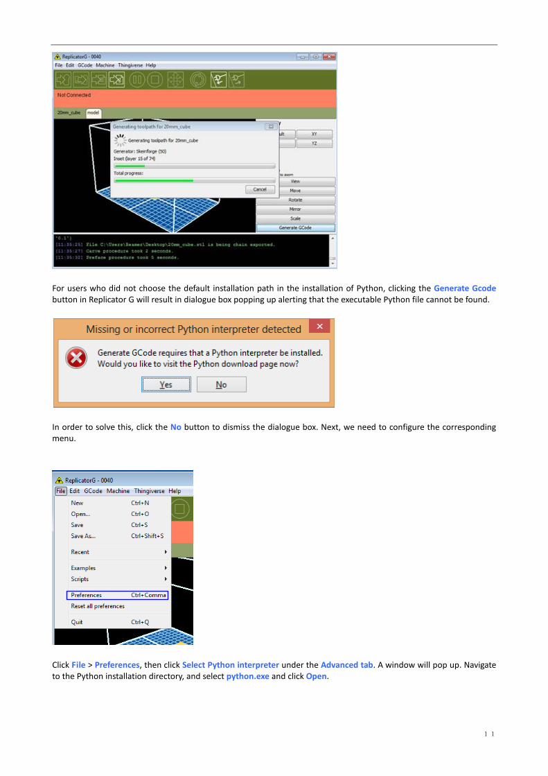
For users who did not choose the default installation path in the installation of Python, clicking the Generate Gcode button in Replicator G will result in dialogue box popping up alerting that the executable Python file cannot be found.
In order to solve this, click the No button to dismiss the dialogue box. Next, we need to configure the corresponding menu.
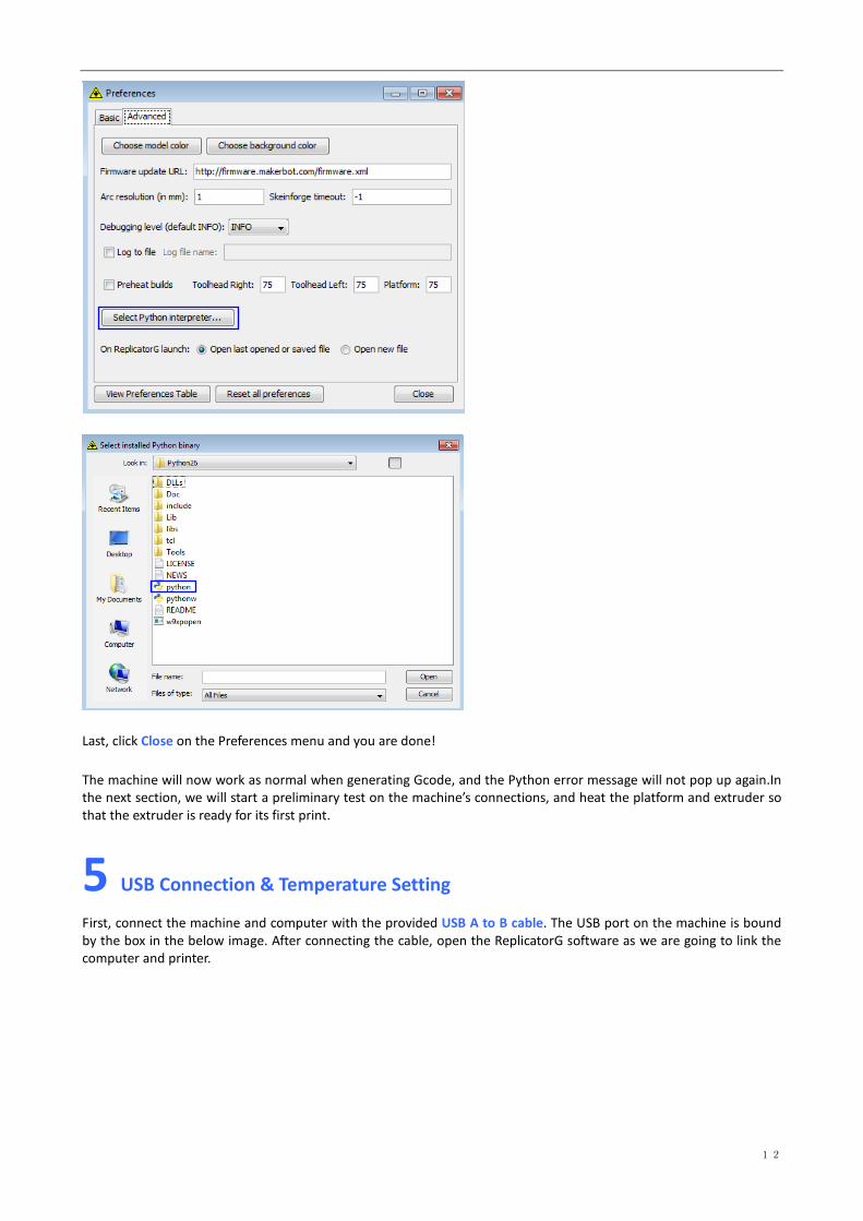
Click File > Preferences, then click Select Python interpreter under the Advanced tab. A window will pop up. Navigate to the Python installation directory, and select python.exe and click Open.
12
Last, click Close on the Preferences menu and you are done! The machine will now work as normal when generating Gcode, and the Python error message will not pop up again.In the next section, we will start a preliminary test on the machine’s connections, and heat the platform and extruder so that the extruder is ready for its first print.
5 USB Connection & Temperature Setting
First, connect the machine and computer with the provided USB A to B cable. The USB port on the machine is bound by the box in the below image. After connecting the cable, open the ReplicatorG software as we are going to link the computer and printer.

13
Inside the ReplicatorG software, click Machine > Connection (serial port) > Rescan serial ports, if no new ports appear then the software driver has not been installed. To install the driver manually, go to My computer and right click on Properties. The basic system parameters appear. Next select Device Manager.
Locate the software driver shown in the blue box above. Right click and select Update Driver Software.

14
Click Browse my computer for driver software to find the location of ReplicatorG0040 on your system.
Click FTDI USB Drivers in the driver folder before confirmation and click OK. The drivers will then be installed. The next step is to link the printer. Rescan the serial ports and select the one that appears on your machine (on our test machine the port was COM10, but different computers vary).

15
Now we can link the machine to the computer. Click on the printer connect icon highlighted in blue :
If the printer connect icon turns dim, as shown in the illustration below, the printer has successfully connected to the computer. Next we need to preheat the extruder and build platform.
In the same set of menu, click on the cross-shaped icon and a new interface will appear.

16
Input the following target values: 220°C for the extruder and 115°C for the heating platform. After entering the values, the platform will start to warm up. When the extruder temperature reaches 50°C, the cooling fan will be activated and the current temperature value will display to the right as shown below.
6 Filament
To make the process of feeding or withdrawing the filament easy, please follow the next few steps carefully: After inserting the filament into the feeding hole, do not push it further until the extruder temperature reaches 200°C or more. Once the machine reaches this point, you will feel the filament being pulled into the extruder head.
6.1 Install Filament
First, remove the filament guide tube from the extruder head.

17
When you have removed the guide tube you can remove the filament that is inside the guide tube. To avoid any blockages during printing, please ensure that the two threads are loaded from the middle. There are two wire trays, one runs clockwise and the other one runs counter - clockwise, as shown below:
There are two ways of feeding the filament into the extruder head, one is using the LCD screen on the printer itself and the other is by using the control panel on the Replicator G software.
6.2 Feeding the Filament Using the LCD Screen
1. Turn on the Creator Pro; the display will indicate: ▶ Print from SD Preheat Utilities
2. Using the directional arrows to the right of the screen, press the page down key to scroll to the next page. The display will show:
Preheat ▶ Utilities Info and Settings
3. Select Utilities; press the OK key of the keypad. The display will show: Monitor Mode ▶ Filament loading Preheat Setting Level Build Plate

18
Feed operation with LCD screen
4. Select Filament loading; press the OK key of the keypad. The display will show: ▶ Load Right Unload Right Load Left Unload Left
5. Select the appropriate side of the extruder you wish to load(Left or Right for models with dual extruders). Press the OK key again on the keypad. The display will indicate: I'm heating up my extruder!” At this time, the temperature of the right nozzle is being heated up. When the temperature of the nozzle reaches its target temperature, pressing the OK key on the keypad, and the nozzle should start extruding material. If not, keep pressing the OK key unit it does.
6.3 Withdrawing the Filament Using LCD Screen
1) Turn on the Creator Pro, the display will indicate: Build from SD ▶ Preheat Utilities 2) Using the directional arrows to the right of the screen, press page down key to scroll to the next page and
select Preheat, Press OK key on the keypad, then you will see: ▶ Start Preheat Right Tool OFF Left Tool OFF Platform OFF 3) Press page down key to select Left Tool (or Right Tool), click OK key, you will see: ▶Start Preheat Right Tool ON Left Tool ON Platform OFF 4) Press page up key back to Start Preheat, and Press OK key, you will see: Heating: R Extruder: 033/230C L Extruder: 033/230C Platform: 024
This means the left extruder is heating up, when it reaches 220°C. First push in the filament a little bit until you see
filament come out of the nozzle, then pull it out quickly. This will ensure you have withdrawn the filament inside the
nozzle successfully.
6.4 Feeding the Filament Using Replicator G Control Panel
The following can only be performed while the printer is connected to the computer. Open the Replicator G software, click the icon in the red box, this is the control panel icon. The dialogue box shown below will then pop up.
CAUTION
If you just finished your printing or already extruded the filament and want to withdraw the filament, at this moment, the extruder is still over 200°C, first push the filament in a little further, and then directly pull it out.
If you want to change another color filament, first you need to withdraw filament and then load in. Please do as following shown to avoid filament jam.

19
To heat the right extruder and feed material, click the right extruder on the upper right corner of the control panel and manually modify the temperature in the “Right Target” setting for the extruder temperature control changing the temperature to 220°C. A red line will be plotted in the temperature map. When the actual (Current) temperature reaches 220°C you can pull the filament out.
6.5 Setting Parameters
Before generating Gcode, specific parameters can be set up to customize various aspects of the print. An explanation to each of the settings can be found in the EXPLANATION OF GCODE SETTINGS.
7 Initial Print
First, make sure that you’ve completed all the steps in the Un-boxing and Hardware Setup section.
1. Your dual extruder heads should be bolted in place, 2. Your filament guide tubes is connected, 3. Your filament is mounted on the spool holders.
Once all these have been completed, you can plug in your power supply. If everything is ready, then turn on the power switch on the back of your Creator Pro. Every printer will be leveled before shipped out, but we can’t ensure that the platform won’t move during delivery, so it will be better to level platform before you begin to print. We will put one SD card within the 3D printer,there is a file named PlateLeveling.x3g.Put the SD card into the slot,choose Print from SD ,click OK,then choose PlateLeveling.x3gand click it, you will see the content below:Find the 3 knobs on the bottom of the platform and tighten four or five turns.I'm going to move the extruder to various positions for adjustment.In each position, we will need to adjust 2 knobs at the same time. Nozzles are at the right height when you can just slide a sheet of paper between the nozzle and the platform. Grab a sheet of paper to assist us. Please wait.You will find 3 knobs under the platform,the extruder will move to different locations, in everylocation, you need to rotate2 knobs toadjust.You can put one piece of paper between nozzle and platform,ifwhen you move the paper and can feel thefriction(which means you can move the paper but it can’t be scratched ), then level finished During the process, what you should do is only click OK continuely, the screen will go to next page; and you also only
CAUTION
Creator Pro has been leveled perfectly before leaving factory. However, it will get unleveled during long distance shipping, please do level the build plate again before starting a print. See below in instruction.

20
need to click OK, the extruder will move to next point. Attention please: when the 2 knobs level finished, you only need to click Print Another Copy, then the extruder will continue to the third point, four points can be level finished
Now, let’s start the initial print. Click File > Examples and then select the 20mm_Calibration_Box.stl. The preview interface will then appear along with a virtual impression of the 20mm cube on the virtual printer bed. On the preview interface click Move > Center and Put on platform so that the sample will be printed on the center of the build plate.
21
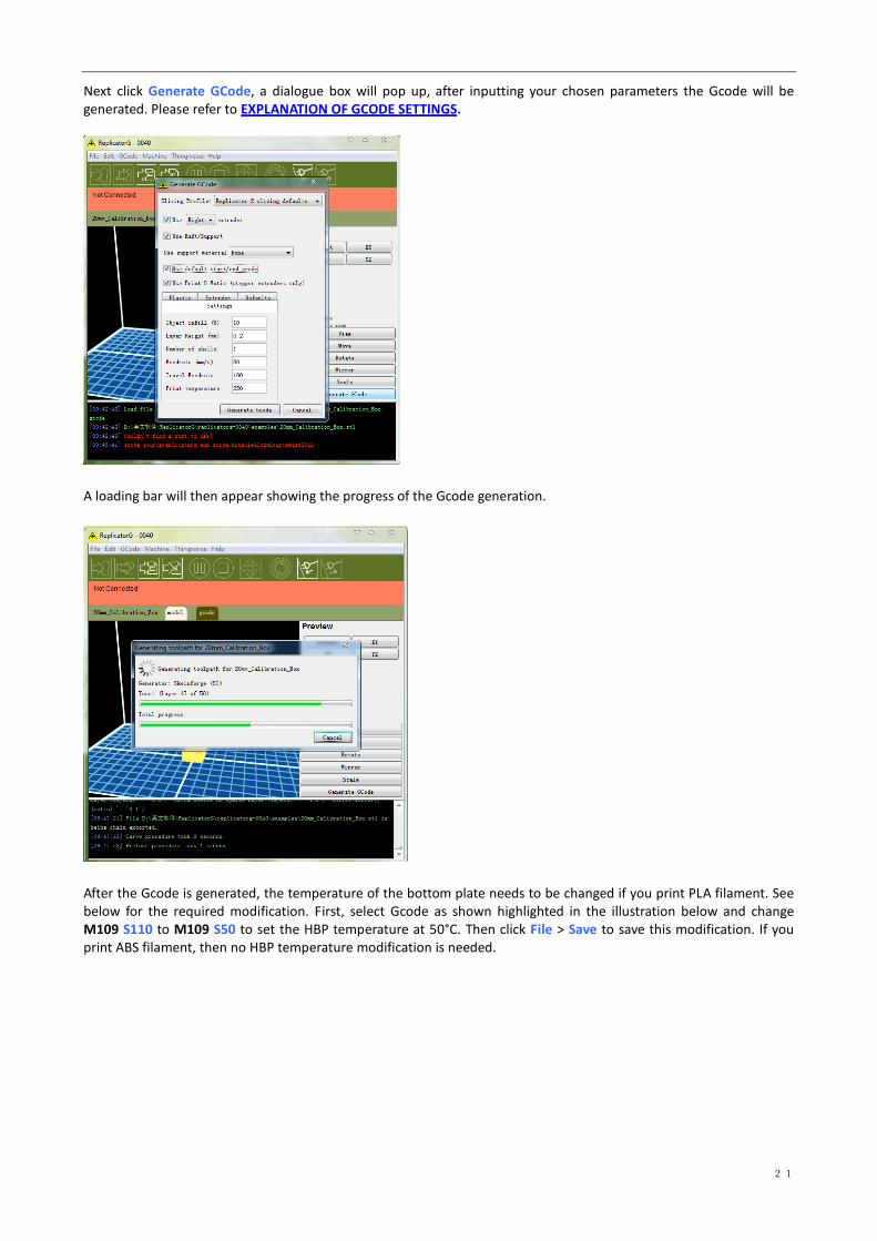
Next click Generate GCode, a dialogue box will pop up, after inputting your chosen parameters the Gcode will be generated. Please refer to EXPLANATION OF GCODE SETTINGS.
A loading bar will then appear showing the progress of the Gcode generation.
After the Gcode is generated, the temperature of the bottom plate needs to be changed if you print PLA filament. See below for the required modification. First, select Gcode as shown highlighted in the illustration below and change M109 S110 to M109 S50 to set the HBP temperature at 50°C. Then click File > Save to save this modification. If you print ABS filament, then no HBP temperature modification is needed.

22
If you have connected Replicator G Creator Pro printer, click the left most button on the green bar near the top of the screen. The Gcode has now been sent to the printer and the object will start printing shortly. If not, please refer to USB Connection & Temperature Setting to connect.
8 Dual Extruder Print
Open ReplicatorG and select Gcode > Merge .stl for Dual Extrusion. You will see following:

23
Click on the first Browse button to locate and select the file for left extruder; and then click on the second Browse button for right extruder. For example, you can find the examples folder in its installation path. Open the folder examples select Two_color_world_a.stl for left extruder and repeat the process for the right extruder as shown below:
Now you need to save it to the desktop with the suffix format .gcode. Click Merge, two dialogue boxes will then pop up. NOTE: Do not check "the 'use raft/support' option. If you want to print dual colors with PLA filament, then perform the following settings:
24
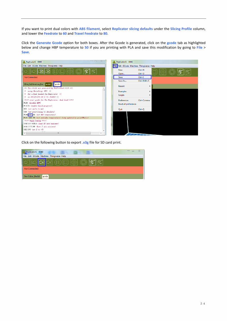
If you want to print dual colors with ABS filament, select Replicator slicing defaults under the Slicing Profile column, and lower the Feedrate to 60 and Travel Feedrate to 80. Click the Generate Gcode option for both boxes. After the Gcode is generated, click on the gcode tab as highlighted below and change HBP temperature to 50 if you are printing with PLA and save this modification by going to File > Save.
Click on the following button to export .x3g file for SD card print.