zhihan xu, matt proctor, ilia voloh - umn ccaps xu, matt proctor, ilia voloh ... = 180 (ex ternal f...
TRANSCRIPT

Zhihan Xu, Matt Proctor, Ilia Voloh
- GE Digital Energy
Mike Lara - SNC-Lavalin
Presented by: Terrence Smith GE Digital Energy

CT fundamentals – Circuit model, excitation curve, simulation model
CT saturation – AC saturation, DC saturation
Simplified CT saturation analysis
Effects of CT saturation on 87L
Techniques to improve CT saturation tolerance for 87L applications
CT saturation analysis tool for 87L
2
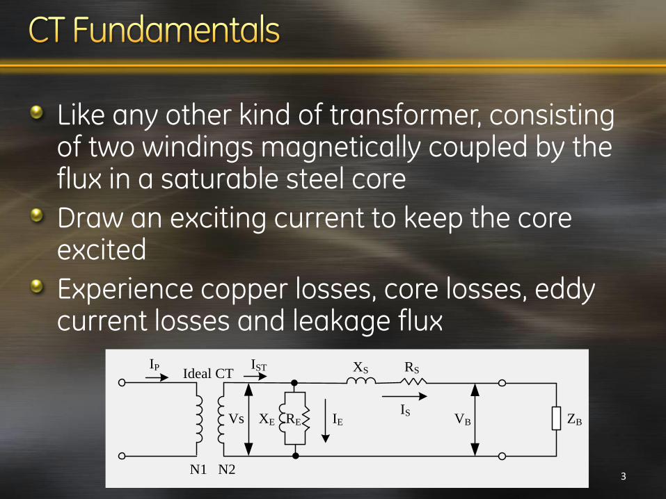
Like any other kind of transformer, consisting of two windings magnetically coupled by the flux in a saturable steel core
Draw an exciting current to keep the core excited
Experience copper losses, core losses, eddy current losses and leakage flux
N1 N2
IP IST
ISIEVs XE RE VB
XS RS
ZB
Ideal CT
3

More practical way to represent the CT steady-state performance
10-5
10-4
10-3
10-2
10-1
100
101
10-2
10-1
100
101
102
103
Exciting Current (A, rms)
Excitin
g V
olta
ge
(V
, rm
s)
Knee point voltage (148V) per IEEE
Saturation voltage
CT Ratio: 2500/5A
Secondary resistance: 0.782 ohm
Knee point voltage (157V)
per IEC
Provided by manufacturers
Verified during field tests
4

IEEE PSRC model
Assume the single-valued saturation curve
Ignore curve in the below-knee-point region
Actual curve
Simplified Curve
10A
Excitation Current (A, rms)
Exci
tati
on V
olt
age
(V, rm
s)
VsSlope=1/S
5

Steady state saturation
Caused by the symmetrical current with no DC component
0.015 0.02 0.025 0.03 0.035 0.04 0.045 0.05-1.5
-1
-0.5
0
0.5
1
1.5
Ti me ( s)
Current (pu of fault)
Saturated Secondary
Current (15-65kA)
Ratio Current
CT Ratio: 800/5
Burden: 2 ohms
Vs@10A: 303 V
DC offset: 0%
SSX ZIV
To avoid AC saturation
6

Transient saturation
Caused by DC component in the fault current, unipolar half wave current or remnant flux in the CT
To avoid DC saturation
0.02 0.03 0.04 0.05 0.06 0.07 0.08
-1
-0.5
0
0.5
1
1.5
2
2.5
Ti me ( s)
Current (pu of fault)
Saturated Secondary
Current (15-65kA)
Ratio Current
CT Ratio: 800/5
Burden: 2 ohms
Vs@10A: 303 V
DC offset: 100%
)1(R
XZIV SSX
7

High primary fault current
Excessive secondary burden
Heavy DC offset in current
Large percent remanence
8

Nonlinear exciting current during saturation affects the performance of current-based protection elements
0.02 0.04 0.06 0.08 0.1 0.12 0.14-1.5
-1
-0.5
0
0.5
1
1.5
2
Time (s)
Sa
tura
ted
Cu
rre
nt a
nd
Ma
gn
itu
de
(p
u o
f fa
ult)
Ip=15kA
Ip=65kA
0.02 0.04 0.06 0.08 0.1 0.12 0.140
20
40
60
80
100
120
Time (s)
An
gle
Sh
ift (d
eg
ree, le
ad
ing)
Ip=15kA
Ip=65kA
9

Exact same samples during unsaturation
Saturated current samples are zero during saturation
Saturation is repeated each half cycle with the same pattern
0 0.005 0.01 0.015 0.02 0.025 0.03 0.035-1.5
-1
-0.5
0
0.5
1
1.5
Ti me ( s)
Current (pu)
Ideal Current
Saturated Current
No dc offset
The time to saturation longer than half cycle is not considered since 87 function operates at high speed
10

-0.01 -0.005 0 0.005 0.01 0.015 0.02 0.025 0.030
0.2
0.4
0.6
0.8
1
Time (s)
Ma
gn
itu
de
(p
u)
Ideal Current
Saturated Current
-0.01 -0.005 0 0.005 0.01 0.015 0.02 0.025 0.03-100
-90
-80
-70
-60
-50
-40
-30
-20
-10
0
Time (s)
An
gle
(d
eg
ree
)
Ideal Current
Saturated Current
Time to saturation: 2.86 ms @ 60Hz
Magnitude: 0.3 pu of ideal
Angle: leading ideal by 51.3° 11

Adjust time to saturation from 0 to 0.5 cycle M
ag
nitu
de
(α
, p
u o
f id
ea
l)A
ng
le S
hift fro
m Id
ea
l (β, d
eg
ree
, lea
din
g)
RM
S (
pu
of id
ea
l)
5 10 15 20 25 300
0.2
0.4
0.6
0.8
1
Time to saturation (1/64 cyc)
5 10 15 20 25 300
20
40
60
80
100
12
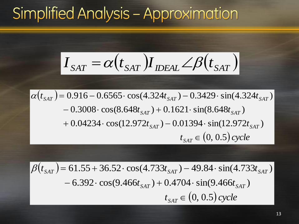
SATIDEALSATSAT tItI
cyclet
tt
tt
ttt
SAT
SATSAT
SATSAT
SATSATSAT
5.0,0
)12.972sin(01394.0)12.972cos(04234.0
)648.8sin(1621.0)648.8cos(3008.0
)324.4sin(3429.0)324.4cos(6565.0916.0
cyclet
tt
ttt
SAT
SATSAT
SATSATSAT
5.0,0
)466.9sin(4704.0)466.9cos(392.6
)733.4sin(84.49)733.4cos(52.3655.61
13

Consider internal faults in a two-terminal line
Traditional percentage differential plane is analyzed
))(()(
SATPSATR
PL
tKItI
II
γ is an angle difference tolerance factor
K is a magnitude difference tolerance factor Different fault current level at the remote end
Different CT performance between two CTs
Model difference between simplified saturation and real saturation
Other errors caused by DC offset, asymmetrical saturation, etc.
14

87L operates correctly if
15
))(()(1
))(()(
SATSATP
SATPSATPRLDIFF
tKtI
tKItIIII
KtI
KItIIII
SATP
PSATPRLRES
)(1
)(
2
1
)()cos(211
2
SLPK
KK
K
KKDF
1
)()cos(21 2
Define Dependability Factor

16
87L correctly operates on internal faults if DF > 0.7, that is, SLP2 need to be set less than 0.7
γ (degree)
Time to saturation (1/64 cyc)
0
20
5 10 15 20 25 30
0.86
0.88
0.9
0.92
0.94
0.96
0.98
1
De
pe
nd
ab
ility
Fa
cto
r
K=1
γ (degr
ee)
Time to saturation (1/64 cyc)
-20
0
205 10 15 20 25 30
0.7
0.75
0.8
0.85
0.9
0.95
1
De
pe
nd
ab
ility
Fa
cto
r
K=10

17
)180)(()(
SATPSATR
PL
tKItI
II
))(()(1
)180)(()(
SATSATP
SATPSATPRLDIFF
tKtI
tKItIIII
KtI
KItIIII
SATP
PSATPRLRES
)(1
)(
87L misoperates if
1
12
)()cos(21
12
)(1 2
KSLP
KK
KSLP
K
K
KKSF
1
)()cos(21 2
Define Security Factor

18
There exists misoperation if time to saturation is less than 2.6 ms when SLP2 is set to 0.7
5 10 15 20 25 300
0.1
0.2
0.3
0.4
0.5
0.6
0.7
0.8
0.9
1
Ti me t o sat ur at i on ( 1/ 64 cyc)
Security Factor
K=0.9
K=1.0
K=1.1Misoperations
SLP2=0.7

19
100% Line
Operating Zone
Restraint Zone
Ip=6pu Ip=8pu
tSAT -> 0
0 2 4 6 8 10 12 14 160
2
4
6
8
10
12
14
16
Restraint Current (pu)
Diffe
ren
tia
l C
urr
en
t (p
u)
tSAT -> 0.5 cyc
Misoperations
PKP=0.3
BP=3
SLP1=30%
SLP2=60%
Add a portion of current distortions such as harmonics, saturated CT signal and noise, into the restraint signal; therefore, the restraint region is adaptively increased.
Dynamically switch the differential settings to more secure values to deal with external faults. Normally, the more secure settings would result in the larger restraint region.
Constantly use the transient bias as the additional restraint signal. A delta signal is mixed into the transient bias to increase the restraint signal.
20

Adaptive restraint dynamically adjusts the operating-restraint boundary.
Adaptive decision process is based on an on-line computation of measurement error.
Squared differences between the actual waveform and an ideal sinusoid is a measure of a “goodness of fit” (a measurement error)
21

Dynamically increase the weight of the adaptive restraint portion in the total restraint quantity, but for external faults only
22
arg(ILOC/IREM)=0
(internal fault)
MULT=1
MULT=1
MULT=abs(arg(ILOC/IREM)×5/180
arg(ILOC/IREM)=180(external fault)
MULT=5

23
Total restraint = Traditional restraint
+ Weight factor * Adaptive restraint
Imaginary (ILOC/IREM)
Real (ILOC/IREM)
OPERATE
REST.
Error factor is high
Error factor is low
It is necessary to develop a type of CT saturation analysis tool because
Utility customers are looking for the relay manufacturer recommendations and warranties for the CT selection at their system with particular relay models.
CT selection recommendations are different from one manufacturer to another and there cannot be any standard giving specific recommendations.
24
A practical CT saturation analysis tool is required to
seamlessly incorporate the CT performance and relay system application
utilize the commonly recognized CT model and CT saturation calculation algorithm
simulate the analog/digital signal processing and data calculations exactly existing in the line current differential relay
25
A practical CT saturation analysis tool is able to Analyze reliability of 87L during CT saturation
Evaluate the differential relay security
Investigate the effect of adjusting 87L settings
Choose the proper size of CT
Examine possibility of reducing CT requirement
26

27

28

Based on the simplified saturation analysis, The saturation caused by internal faults will rarely result in the failure to operate
The saturation caused by external faults introduces a spurious differential current that may cause 87L to misoperate.
Adaptive restraint technique used in 87L to tolerate CT errors, reduce CT requirement and improve relay security
Necessity, function requirement, and example of a practical CT saturation analysis tool
29
