zld-systems - xzero · introduction everyone needs water. supplies of water are vital for...
TRANSCRIPT

ZLD-systems
An Overview
Fredrik Tillberg Department of Energy Technology Royal Institute of Technology, KTH Stockholm, 2004
1

Introduction Everyone needs water. Supplies of water are vital for agriculture, industry, recreation and human consumption. One problem that the water industry faces is disposal of concentrate from advanced water treatment processes. This report discusses Zero Liquid Discharge(ZLD) systems, one possible solution to concentrate disposal. ZLD disposal is the only option currently available in many inland regions where surface water, sewer, and deep well injection disposal are prohibited. A ZLD-system can produce a clean stream from industrial wastewater suitable for reuse in the plant and a concentrate stream that can be disposed, or further reduced to a solid. Furthermore, the prevalent technologies used for ZLD-systems and different types of components in a ZLD-system are being described as well as the possibility of integrating Xzero’s MD-technology into a ZLD-system. An overview of interesting competitors and their technologies are also presented.
2

Contents Contents...................................................................................................................................... 3 Field of application..................................................................................................................... 4 Different ZLD-systems .............................................................................................................. 4
Designing a ZLD-system ................................................................................................... 5 General guidelines.............................................................................................................. 5 General ZLD-system in a power plant ............................................................................... 6 Ionics’ EnChem. A ZLD-solution for the semiconductor industry.................................... 7 Tenergys’ plating waste water recovery system ................................................................ 8
Description of components......................................................................................................... 9 RO ...................................................................................................................................... 9 EDR.................................................................................................................................... 9 Evaporator .......................................................................................................................... 9 Crystallizer ....................................................................................................................... 10 Spray dyer ........................................................................................................................ 11
Integrating Xzero’s MD-technology into a ZLD-system......................................................... 12 Example of a ZLD-system containing a MD-module...................................................... 13
Appendix 1 – Picture and CAD-model of the MD-module ..................................................... 14 Appendix 2 – CAD designs of the MD-module....................................................................... 15
3

Field of application Most industries use water in different processes in some way. However, the waste stream is widely varying in different industries. One of the main problems when designing a ZLD system is how to describe the waste stream. The contamination of the water (the feed chemistry), the flow rate and the purity demand of the water are other factors that are essential when designing a ZLD-system. Because the waste stream is so varying it is impossible to design a general ZLD-system. Every ZLD-system is unique and has to be custom made each time. Today most of the ZLD facilities are primarily industrial and power plant applications. Typical waste streams that produce large volumes of wastewater include cooling tower blowdown, gas scrubbler blowdown, ion-exchange regeneration effluent and rinses, plant washdown and rain water runoff, and process wastes. Typical industries producing these wastewaters are listed below:
• Semiconductor manufacturing • Power industry • Printed circuit board manufacturing • Plating and metal finishing • Food and beverage
As an example one can mention that a typical semiconductor fab consumes 1-2 million litres ultra pure water (UPW) per day. And the feed water flow to be treated in a power plant can be 1000 gpm (gallons per minute). These large quantities of water demands advanced water treatment technology. Different ZLD-systems For over 30 years vapor compression evaporation has been the most useful technology to achieve zero liquid discharge. Evaporation recovers about 95 % of a wastewater as distillate for reuse. Waste brine can then be reduced to solids in a crystallizer/dewatering device. However, evaporation alone can be an expensive option when flow rates are considerable. One way to solve this problem is to integrate membrane processes with evaporation. These technologies are nowadays often combined to provide complete ZLD-systems. The most common membrane processes used so far are reverse osmosis (RO) and electrodialysis reversal (EDR). By combining these technologies with evaporation and crystallization ZLD-systems have become less expensive. They are however combined differently depending on the circumstances, see chapter general guidelines. Together with these components, a variety of other well-known water treatment technologies are used in ZLD-systems for pre-treatment and polishing treatment. These treatments are:
• pH adjustment • degasifier • mixed/separate bed • oil/water separator • neutralization • oxidation (UV, ozone, sodium hypochlorite)
4

• dissolved air flotation (DAF) • carbon adsorption • anaerobic or aerobic digestion
The variation of ZLD-systems are, as previously mentioned, endless. Below, I have tried to display a couple of ZLD-systems applied in different industries. The power plant system, see figure 1, is the most general system, while the other two, see figure 2 and 3, are commercial ZLD-systems from two water treatment companies.
Designing a ZLD-system As mentioned before, characterizing the waste stream is difficult yet essential when designing a ZLD-system. It is important to start off with a realistic estimate of composition, feed chemistry and flow rate. A poorly described waste stream will likely lead to a design which is far from its optimum. The system will either be too large and expensive or too small to achieve the required separation. The selection of the waste water flow rate typically determines the size and therefore the initial capital cost of the ZLD-system. But how do one characterize a waste stream? For existing plants, waste stream compositions can be measured directly, preferably on multiple occasions to characterize a range of compositions. Depending on the process, the feed chemistry may change occasionally, and it is of great importance that one has this in consideration. The most common measurements today include organics, for example, chemical oxygen demand (COD), biochemical oxygen demand (BOD), total organic carbon (TOC) and inorganics (anions, cations, silica).
General guidelines If the water flow rate is small, not many components are necessary. The following general guidelines are accepted today:
• Below 10 gpm of feed – crystallizers and/or spray dyers can be combined. • 10 – 50 gpm of feed – use a crystallizer alone. • 50 – 100 gpm of unsaturated feed – use an RO/EDR/crystallizer combination. • 50 – 100 gpm of saturated feed – use an evaporator/crystallizer combination. • 100 – 500 gpm of feed – either an RO/crystallizer or an evaporator/crystallizer
combination may be the most economical. • 500 – 1000 gpm of feed – all three should be used
5
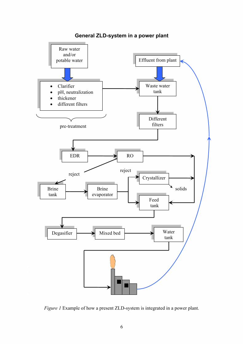
General ZLD-system in a power plant
I ett ZLD-system krävs idag alltid ett första steg där de organiska ämnena först separeras från vattnet. Vanligaste metoder:
• Anaerobic or aerobic digestion, (biological/chemical oxygen demand, BOD,COD) • Ultra/Micro/Nano-filtration • Carbon adsorption • Oxidation (ultraviolet, ozone, sodium hyphochlorite) • Dissolved air flotation (DAF) • Oil/water separator • Stripping, either with air or steam • Softening (chemical or ion exchange) Steg 2, ta bort oorganiska/övrigt material: Vanligaste metoderna:
• RO, Reverse Osmosis • EDR/ED, Electrodialysis Reverse, Electrodialysis • Evaporation • Crystallization
Vad bestämmer uppbyggnaden av ZLD-systemet? • amount of water needed. Few gallons per minute to millions of gallons each day for industries. • flow rate • the feed chemistry, general guidelines: 1. 10-50 gpm of feed – use a crystallizer alone 2. 50-100 gpm of unsaturated feed – use an RO/crystallizer combination; and 50-100 gpm of
saturated feed – use an evaporator/crystallizer combination. 3. 100-500 gpm of feed, either an RO/crystallizer combination may be the most economical. 4. 500-1000 gpm of feed, all three should be used, even if the potentially scaling salts must be
removed by chemical precipitation in front of the RO process. Up to now, resins, membranes, reverse osmosis, electro dialysis, chemichal/physical treatments were used. Even if all those technologies coming from the water treatment field proved to be rather effective, they do involve high costs in term of maintenance, energy and manpower. And they simply cannot face sudden variations in the flowrate and in the consumption of the water to be treated. What is more, they produce a very big volume of wastes (solutions and sludges containing high amounts of pollutants, deactivated or poisoned resins, etc.), which are extremely difficult and expensive to be Figure 1 Example of how a present ZLD-system is integrated in a power plant.
• Clarifier
Figure 1 Example of how a present ZLD-system is integrated in a power plant.
• pH, neutralization er • thicken• different filters
Waste water tank
pre-treatment
Effluent from plant
Raw water and/or
potable water
Different filters
EDR RO
Brine evaporator
Brine tank
Feed tank
Crystallizer reject
reject
solids
Mixed bed Water tank
Degasifier
6

Ionics’ EnChem. A ZLD-solution for the semiconductor industry Ionic claims that their water treatment system, the EnChem, removes more than 99% of the contaminating materials. The EnChem technology is also capable of reducing water usage during the semiconductor manufacturing process by up to 85% through reclaim. Ionics’ EnChem technology is a low pressure water treatment solution. It is specifically designed to reduce water consumption and operating costs. Figure 2 shows how the system works. clean water press solids
Reaction tank
Filtration
Backflush
Settling tank
RO pH
polymer
Feed influent
Figure 2 Ionics’ ZLD-system for the semiconductor industry The water to be treated has to go through four steps; through the reaction tank, on to the filtration, on to the backflush and finally to de-watering. Each step is described below: Step 1. Reaction step. Influent waste water is pH adjusted, then mixed with organic and inorganic coagulent additives. The polymers react with the contaminants to form spheres. The reaction is complete in a few minutes. Step 2. Filtration. The filtration is accomplished through low pressure membranes. The clean water then exits the top of the filter while solids are retained on the filter membrane. Operating pressures remain below 15 psi (1 bar). Step 3. Backflush. The membranes are pulsed to remove solids and then solids are pumped to a settling tank. Step 4. Solids formation/De-watering. Solids are pumped to a holding tank for further settling. Conventional filter presses can be used to further separate and de-water solids. Overflow filter press water is returned to the reaction tank.
7
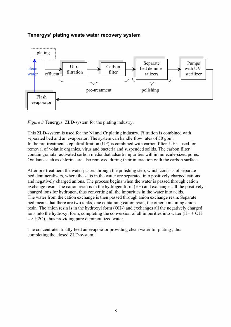
Tenergys’ plating waste water recovery system clean water effluent pre-treatment polishing
plating
Flash evaporator
Ultra filtration
Carbon filter
Separate bed demine-
ralizers
Pumps with UV-sterilizer
Figure 3 Tenergys’ ZLD-system for the plating industry. This ZLD-system is used for the Ni and Cr plating industry. Filtration is combined with separated bed and an evaporator. The system can handle flow rates of 50 gpm. In the pre-treatment step ultrafiltration (UF) is combined with carbon filter. UF is used for removal of volatile organics, virus and bacteria and suspended solids. The carbon filter contain granular activated carbon media that adsorb impurities within molecule-sized pores. Oxidants such as chlorine are also removed during their interaction with the carbon surface. After pre-treatment the water passes through the polishing step, which consists of separate bed demineralizers, where the salts in the water are separated into positively charged cations and negatively charged anions. The process begins when the water is passed through cation exchange resin. The cation resin is in the hydrogen form (H+) and exchanges all the positively charged ions for hydrogen, thus converting all the impurities in the water into acids. The water from the cation exchange is then passed through anion exchange resin. Separate bed means that there are two tanks, one containing cation resin, the other containing anion resin. The anion resin is in the hydroxyl form (OH-) and exchanges all the negatively charged ions into the hydroxyl form, completing the conversion of all impurities into water (H+ + OH- --> H2O), thus providing pure demineralized water. The concentrates finally feed an evaporator providing clean water for plating , thus completing the closed ZLD-system.
8
Description of components
RO Reverse osmosis is a process where water is pressurized so that it passes through a semi-permeable membrane, leaving dissolved inorganic salts and silica behind. As a rough guide to performance, RO can produce a concentrate containing 30000 ppm total dissolved solids (TDS). Two problems with RO are that organics will seriously foul RO systems and that RO requires a feed stream that is free of suspended solids. Because of this it is advisable to remove organics from wastewater before it enters the RO, so extensive front-end filtration equipment is required. Some membranes are pH and temperature sensitive, so pH control and feed equalization may be necessary. RO is also quite energy-intensive. The advantage of RO over evaporation is that the life cycle costs of RO are about half those of evaporators.
EDR Electrodialysis reversal (EDR) is a membrane process in which electrolytes migrate across charge-selective membranes in response to an electrical field. In EDR, the polarity of the electrodes is reversed several times an hour and the fresh water and the concentrated wastewater are exchanged within the membrane stack to remove fouling and scaling. EDR differs from RO in that the ions are removed and the water is left behind, whereas in RO, the water is removed and the ions are left behind. Because of this, silica and dissolved organics are not removed with an EDR process, which is an important aspect to remember when the clean stream is reused. Like RO, EDR requires solids and organics removal from the feed for reliable operation.
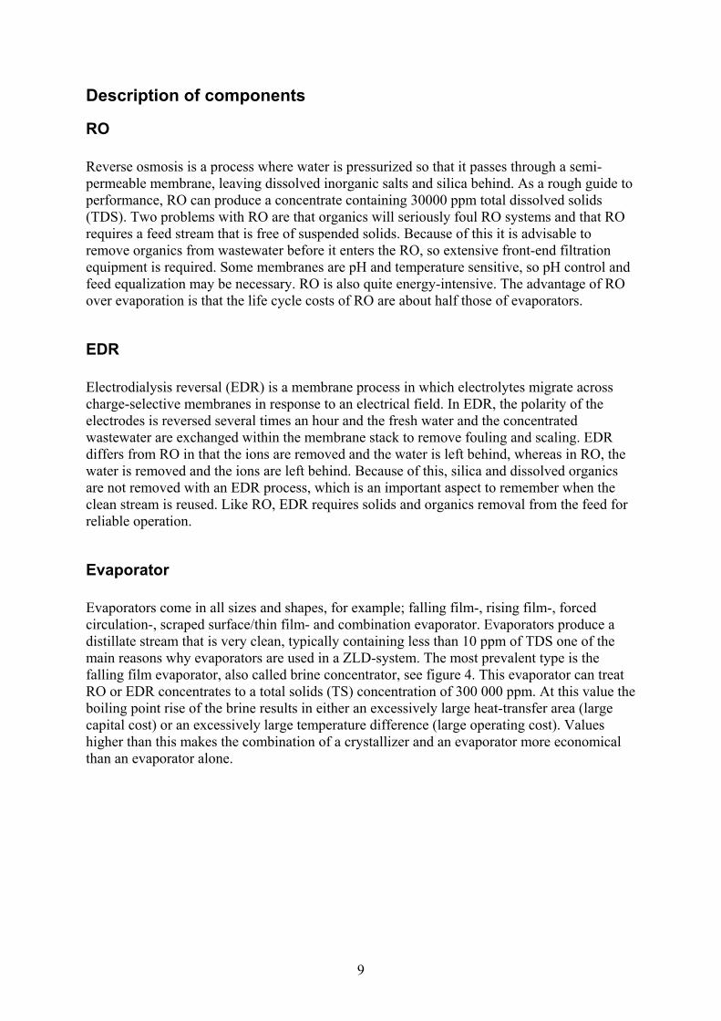
Evaporator Evaporators come in all sizes and shapes, for example; falling film-, rising film-, forced circulation-, scraped surface/thin film- and combination evaporator. Evaporators produce a distillate stream that is very clean, typically containing less than 10 ppm of TDS one of the main reasons why evaporators are used in a ZLD-system. The most prevalent type is the falling film evaporator, also called brine concentrator, see figure 4. This evaporator can treat RO or EDR concentrates to a total solids (TS) concentration of 300 000 ppm. At this value the boiling point rise of the brine results in either an excessively large heat-transfer area (large capital cost) or an excessively large temperature difference (large operating cost). Values higher than this makes the combination of a crystallizer and an evaporator more economical than an evaporator alone.
9
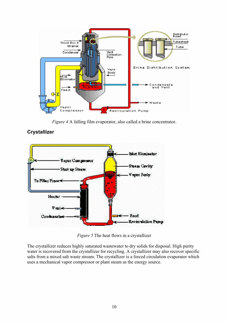
Figure 4 A falling film evaporator, also called a brine concentrator.
Crystallizer
Figure 5 The heat flows in a crystallizer
The crystallizer reduces highly saturated wastewater to dry solids for disposal. High purity water is recovered from the crystallizer for recycling. A crystallizer may also recover specific salts from a mixed salt waste stream. The crystallizer is a forced circulation evaporator which uses a mechanical vapor compressor or plant steam as the energy source.
10
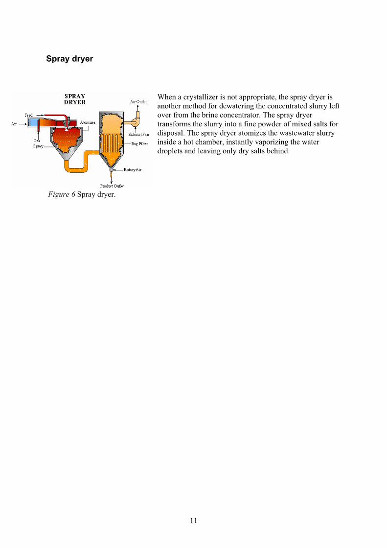
Spray dryer
When a crystallizer is not appropriate, the spray dryer is another method for dewatering the concentrated slurry left over from the brine concentrator. The spray dryer transforms the slurry into a fine powder of mixed salts for disposal. The spray dryer atomizes the wastewater slurry inside a hot chamber, instantly vaporizing the water droplets and leaving only dry salts behind.
Figure 6 Spray dryer.
11
Integrating Xzero’s MD-technology into a ZLD-system Membranes are expected to play critical roles in future ZLD solutions. Membrane technologies are available in a range of configurations and operating modes, and can be pressure or vacuum-driven, or use electrical potential as the driving force as in the case of EDR membranes. The membrane technologies commercially available today consist of the following: • Microfiltration (MF) membranes – used for removal of suspended solids and bacteria. • Ultrafiltration (UF) membranes – used for volatile organics and virus removal, as well as the removal capabilities listed for MF membranes. • Nanofiltration (NF) membranes – used for water softening and sulfate removal. • Reverse osmosis (RO) membranes – used for salt removal for brackish and seawater. • Electrodialysis reversal (EDR) membranes – used for salt removal for brackish water. The prevalent membrane technologies used to day in ZLD-systems are RO and EDR. These technologies have as described in chapter ‘description of components’ both advantages and disadvantages. One possible solution instead of RO and EDR is MD technology. The advantages with MD are as follows:
• Less complicated than its competitors. • not pH or chemical sensitive leading to fewer steps for pre-treatment. • not so sensitive for changes in the feed chemistry. • the purity and quality of the water is constantly higher.
One possible disadvantage:
• big costs. Figure 7 shows a possible integration of the MD technology into a ZLD-system.
12

Example of a ZLD-system containing a MD-module
pre-treatment Figure 7 The MD technology integrated into a ZLD-system. solids
Filter Degasifier MD Polishing
loop
Crystallizer Evaporator
Effluent
Figure 8 The MD-module connected to a degasifier.
13
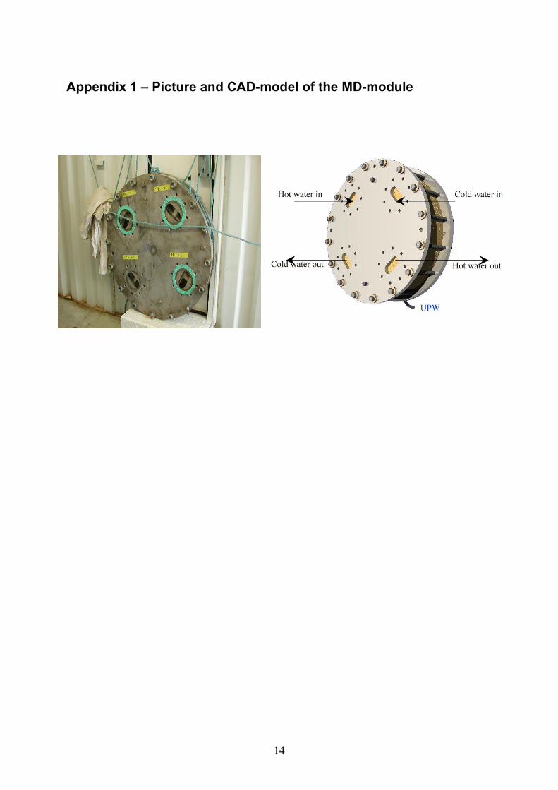
Appendix 1 – Picture and CAD-model of the MD-module
14

Appendix 2 – CAD designs of the MD-module
Frontal view Side view
Back view
15