zomeworks - cloud object storage | store & retrieve ... schedule 40 – 8” nominal • heavier...
TRANSCRIPT

UTRF-Series Track Racks™
Assembly Instructions
1011A Sawmill Road NW, PO Box 25805, Albuquerque, NM 87125 USA(505) 242-5354 / (800) 279-6342 / FAX (505) 243-5187
E-mail: [email protected]
ZOMEWORKS

Thanks!
Thank you for your purchase of a Zomeworks Track Rack™. The Zomeworks Track Rack is an ingenious and economical way to increase the annual output of photovoltaic modules by an average of 25% over those mounted on a fixed array.
Tracker Operation
The Track Rack™ changes its orientation to the sun by shifting a mass of refrigerant between canisters on the east and west sides through a copper tube located at the southern-most end of the canisters. Aluminum “shadow plates” vary the amount of sunlight hitting both canisters. When the rack is not directly facing the sun, the canister farther from the sun absorbs more heat and builds pressure. This forces the fluid to move to the other canister, resulting in movement of the rack. Tracking is the result of a constant search for equilibrium. This process is effective throughout a very wide temperature range, and works well even in hazy and intermittent light conditions.
Choosing A Location
Choose a location where the tracker will receive clear, unobstructed light throughout the day. Keep in mind that the Sun rises and sets north of east and west in the summer, and rises and sets south of east and west in the winter. It is particularly important that your Track Rack™ receive morning light that is unshaded by structures, trees, bushes, etc. As the rack starts the day facing west (the position as of the previous sunset), clear morning light is required to “flip” the rack to the east. Morning shadows will delay wake-up time.
Trackers and Wind
The shock absorbers are the first line of defense for the Track Rack™ against wind. They prevent sudden gusts from pushing the rack off-course, as well as restricting any violent movement that may harm the rack and modules. The shocks yield to a constant force by design, thus promoting tracking and, as a result, will be affected in a constant wind-loading situation. The bumper bolt/s are the second failsafe in the structure. They prevent catastrophic failure from occurring by limiting the overall travel of the Track Rack™.

Part Names
1) Gimbal2) Axle Tube3) Seasonal Adj. Bar4) Shock Mounting Arm5) Truss Tube6) Rail Slider7) Canister Slider8A) Canister Set8B) Transfer Tube9) Mounting Rail10) Shock Absorber11) Counterweight Arm12) 25 lb Counterweight13) Shadow Plates14) Storm Collar
Recommended Tools:
• (2ea) Adjustable 12” Crescent Wrenches• (2ea) 1-1/8”, 15/16”, 3/4”, 9/16”, and 7/16”
Open-End Wrenches• Tape Measure• Rubber Mallet (to protect finish)• (2ea) 6' Stepladders
• 15' Rope (medium weight)• Permanent Marker• 5/32” Allen Wrench (provided)• Ratchet Straps for Storm Collar (or similar)• Two Sawhorses (not required, but useful)
Pole Installation
Zomeworks can only provide general guidelines for the design and installation of the mounting pole. Our recommended hole diameters and depths are based on “typical soils”. For installations in sandy or muddy areas, for tall mounting poles, or for any situation different than what is described in these instructions, you should consult a local structural engineer. Large trackers can receive very high wind loads – so a sufficiently strong pole and foundation is crucial. The height of the pole must provide adequate ground clearance for the rack and mounted modules. Zomeworks can provide assistance for spacing multiple racks to avoid shading.
NOTE: ZOMEWORKS CORPORATION ASSUMES NO LIABILITY FOR THE STRUCTURAL INTEGRITY OF THE POLE AND ITS INSTALLATION. SOIL AND WIND CONDITIONS VARY. IF THERE IS ANY DOUBT, CONSULT WITH A LOCAL STRUCTURAL ENGINEER. TALK TO YOUR CERTIFYING ENGINEER BEFORE THE POLE IS INSTALLED!
• The correct pipe (to be provided by customer) is as follows:UTRF-064, UTRF-090, UTRF-120 Schedule 40 – 6” nominal

UTRF-168 Schedule 40 – 8” nominal
• Heavier steel pipe (sch 80 or sch 120) can be used as long as outer diameter is 6.625”
or 8.625” respectively.• Using the chart provided below, find the MINIMUM acceptable pole height above your
finished grade. The suggested pole heights will provide approximately 3' of ground clearance with the largest module arrays installed. It is strongly recommended that the pole height meet our minimum specifications.
• The MINIMUM recommended hole depth is 1/3 the total length of the pole – 1/3 in the ground, 2/3 above the ground.
For example: 10' above grade, 5' below grade – 15' total length.
• Center pipe in hole, use a level or plumb line to insure pipe is vertical.• Fill the hole with concrete (3000 psi minimum strength), and recheck verticality.• The pipe may be filled with concrete for added strength (only to approximate ground
level)• Allow concrete and pipe to set for a MINIMUM of 36 hours before installing Track
Rack™
Rack Assembly Instructions
Attaching Gimbal to Pole
• Place Gimbal on top of pole.• Orient Gimbal so that 3/4” x 2” bolts are facing
true south (adjust for magnetic declination)• Tighten bolts to 75-100 ft-lbs torque in turns
to insure both are tight.
MOUNTING POLE RECOMMENDATIONSModel UTR-020 UTRK-040 UTRF-064 UTRF-090 UTRF-120 UTRF-168
Sch 40 SteelPipe (A) 2 12" (3" OD) 3" (3 12" OD) 6" (6 58" OD) 6" (6 58" OD) 6" (6 58" OD) 8" (8 58" OD)
Minimum PoleHeight (B) 76" 84" 96" 108" 120" 144"
Minimum PoleDepth (C) 38" 42" 48" 54" 60" 72"
GroundClearance at
45° Tilt36" 23" 26" 21" 24" 33"
Minimum HoleDiameter (D) 18"Ø 18"Ø 24"Ø 24"Ø 24"Ø 30"Ø
Maximum RackDimensions (as
viewed fromabove)
67" E-W44" N-S
124" E-W48" N-S
124" E-W80" N-S
146" E-W128" N-S
146" E-W150" N-S
169" E-W192" N-S
Capacity(Module Area) 20 ft² 40 ft² 64 ft² 90 ft² 120 ft² 168 ft²
C
B
D
A
SLOPE AWAYFROM POLE
FOR DRAINAGE

3/8” ALL-THREAD ROD CAN BE INSTALLED TO PROVIDE ADDITIONAL RESISTANCE TO UPLIFT AND TWIST. THIS MAY ALSO BE A REQUIREMENT OF THE PERMITTING AUTHORITY.
• With Gimbal oriented properly (set bolts pointed true south), use pre-drilled 7/16” holes as a guide to drill through the pipe on both sides.
• Slide the all-thread through the Gimbal and pipe, using two 3/8” hex nuts on both sides to fix it in place.
Attaching Shock Mounting Arm(s) to Axle
• If using one Shock Mounting Arm mount on north-facing end of Axle as shown.
• Bolt Shock Mounting Arm to Axle using 1/2” x 1-3/4” hex bolts, flat washers, and Nylock nuts.
• Notice orientation of Shock Mounting Arm. The two welded pieces of round are designed to “wrap” around the tab on the Axle.
• Torque fasteners to approximately 80 ft-lbs. This is a high-stress junction and should be checked periodically.
• If using two Shock Mounting Arms, repeat installation on south end of Axle.
Attaching Axle to Gimbal
• Orient the Axle so that the Shock Mounting Arm(s) are hanging below.
• Align the center hole (3/4”) of the Axle with the holes on the Gimbal tabs.
• Insert the 3/4” x 6” hex bolt and flat washer on the side opposite the small welded tab (see diagram).
• The full size 3/4” hex nut goes on first and fits tightly against the welded tab to prevent spinning.
• The jam nut (thinner) goes on top of the regular hex nut.
• When the rack is fully assembled, the bolt and jam nut must be tightened to approximately 100-120 ft-lbs.
• For the purposes of assembly, it is only necessary to tighten the bolt / nuts lightly.
• First tighten bolt then, while preventing bolt from turning, tighten jam nut.

Installing Seasonal Adjustment Arm
• Bolt Seasonal Adjustment Arm to Axle and Gimbal as shown.• Notice holes are offset to one side – the “thin” side faces the Gimbal.• For the purpose of installing subsequent
components, set axle to 7.5 degree tilt.• After final assembly and adjustment, tighten bolts
to 75 ft-lbs.
Bumper Bolt Installation
• The Bumper Bolt Assembly consists of a 1”-8 x 6” hex bolt, a Ø2-1/2” x 4-1/2” rubber bumper, and a 1” hex jam nut.
• Screw the 1” bolt into the Shock Mounting Arm until the jam nut touches the square nut as shown.
• The rubber bumper does not need to be tightened between the bolt head and the jam nut. It should be able to twist easily.
• Tighten the jam nut to at least 150+ ft-lbs torque. This is a high stress component and should be checked periodically.
• If applicable, install Bumper Bolt on second Shock Mounting Arm.
Installing Truss Tubes
• Using 5/32” Allen wrench provided, make sure that the set screws on each Truss Tube bearing are backed out.
• Install Brass Spacer on north end of axle (if not already installed). This spacer prevents the Truss Tube from eventually making contact with the end plate of the Axle, which will inhibit tracking.
• Slide Truss Tube on to the north end of the Axle until the bearing is snug against the

bushing and axle end cap. Tighten set screws.• Refer to the drawing provided with the instruction packet or to the table below. The
required dimension is the center-to-center distance between the two Truss Tubes.
UTRF-064 42 3/4”UTRF-090 62 3/4”
UTRF-120, UTRF-168 74 3/4”
• Slide second Truss Tube on to the south end of the Axle. Using a tape measure, space the southern Truss Tube so that the center-to-center distance (as measured from the square tube sections) is correct. Tighten set screws. Adjustments may need to be made when installing subsequent components.
• Note: The correct orientation of the Truss Tubes is with the square tube hanging below the Axle and the bearings facing away from each other.
• Note: At this point the Truss Tubes may be quite a bit out of alignment. This is because the bearings are designed to “swivel” in their housing. This feature allows the bearings to tolerate misalignment and also prevents flex in the rack from damaging the bearings.
Pre-Installing Sliders
• Depending on the specific configuration of your rack, it will come with different sizes and quantities of Sliders. The two types of Sliders are shown below.
• Some rack configurations may include a set of Extruded Rail-type Sliders that are designed to mount on the reinforced midsection of the Truss Tube. The square tube section of these sliders is noticeably wider.
• If your rack comes with the wider Extruded Rail Sliders, install those first. The correct orientation is with the tab on the top side of the Truss Tube. The included drawing may specify whether the tab should be on the left or right side. If this is the case, install as directed. If not, the orientation is not critical.
• Next, install any regular-size Extruded Rail Sliders.
• Finally, install the four Canister Sliders so that the outside edges are flush with the ends of the Truss Tube. The correct orientation on the UTRF-168, UTRF-120, and UTRF-064 is with the tabs on the top side and the overhanging section

of the tabs facing towards the middle of the rack. On the UTRF-090 the Slider tab will point towards the outside. See drawing.
• Bolts should be tight enough to clamp securely on to the Truss Tube without crushing the square tube wall.
• With bolts adequately pre-loaded, tighten jam nuts.• Extruded Rail Sliders will be aligned and tightened in a later step.
Locking Bar
• The Locking Bar is a 25” long piece of 2” x 2” x 1/8” steel angle (with bolts) that is provided to assist with assembly and can be used to immobilize the rack in anticipation of high-wind events or if the rack needs to be fixed in place.
• The Locking Bar takes the place of one of the shocks.
• Some customers / installers prefer to use the Locking Bar for assembly, while others prefer the convenience of being able to move the rack into different positions.
• Install as shown.
Canister Installation
• Important Note: Fluid is driven between canisters via 1/4” copper tube. When removing the Canister Set from the package and when straightening the transfer tube, be careful to not crimp it. We recommend that at least two people handle the canisters to prevent any damage.
• Orient the Canister Set so that the unit with the wake-up fin is on the west side of the rack (with the wake-up fin underneath the rack). The transfer tube is designed to enter from the bottom (underside) of each canister.
• Bolt the Canister Set to the Canister Sliders with the 3/8” hardware provided. See drawing below.

• Before fully tightening bolts, align the rack visually to remove any twist and by measuring across the diagonals as shown. This will make the rails and modules easier to install.
• With rack aligned, tighten bolts.
* - Some rack configurations (UTRF-064, UTRF-090 only) come with a Protector Angle. This is a long section of steel angle that spans between both canisters and protects the copper tube when rail length is insufficient to do so. If this is provided with your rack, install it now.
Extruded Mounting Rail Installation
• Description: The Zomeworks Extruded Rail is designed to be mounted to the sliders using 3/8” round-head, square-neck bolts. The edges of the extrusion are different – one side has a slot to accommodate standard 1/4” hex bolts and the other *5/16” hex bolts (see diagram at right). When installing rails on to the Truss Tube pay attention to this orientation!
*- Zomeworks only provides 1/4” hardware for modules. For specific modules, 5/16” hardware can be supplied by the customer / installer.
• In order to mount the Extruded Rails in the correct spot, use a permanent marker to layout the position of the Rail Sliders. This can be done a couple of ways:
Method 1: Find the center of the Extruded Rail. Mark lines the “Half Distance” away on both sides of center. Refer to the table below to find the correct distance. These marks will coincide with the centerline spacing of the Truss Tubes.
Rack Model Truss Tube Spacing
Half Distance
UTRF-064 42 3/4” 21 3/8”UTRF-090 62 3/4” 31 3/8”
UTRF-120, UTRF-168 74 3/4” 37 3/8”
Method 2: Take a look at the layout drawing provided in the instruction packet. There is a dimension showing the distance from the cut end of the Extruded Rail to the centerline location of the Rail Slider. With the Extruded Rail in the correct orientation –

the 3/8” slot facing the outside edge of the Rail Slider, and either the 1/4” or 5/16” slot on top (depending on hardware used) – mark a line.
Pre-Installing Mounting Hardware
• Now that the Extruded Rails have been marked, slide the provided module mounting hardware (1/4” or 5/16” x 5/8” hex bolts) into the tracks at the approximate mounting locations. It is only necessary to locate the bolts in the general area of the module frame holes – this will make the installation of the modules easier. Also slide two 3/8” round head bolts to the center of the marked lines.
Installing Rails on Truss Tubes
• Using the marked lines as a guide, align the Extruded Rail to the Rail Sliders. Install one flat washer and Nylock nut. Loosely tighten the nut.
• In the process of installing the rails, use a measuring tape to verify that the rails are square and parallel with the rack.
Installing Modules
• The first module should be installed flush with the edge of both Extruded Rails. Make any required adjustments to get the hex bolts lined up with the module mounting holes before installing the hex nut. Once the module is in place, tighten backing nut to no more than 75 in-lb (6.25 ft-lb) torque. When installing subsequent modules, refer to the layout drawing for the correct spacing between modules, this is usually 1/4” to 1/2”.
• When all modules have been installed, verify that everything is square and the modules are equidistant from the center axle. Tighten hardware if necessary.
• Use the zip-ties provided to route the copper transfer tube along the backside of the modules.
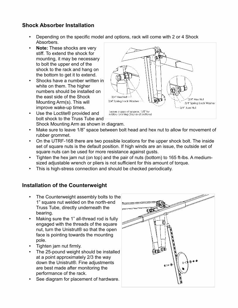
Shock Absorber Installation
• Depending on the specific model and options, rack will come with 2 or 4 Shock Absorbers.
• Note: These shocks are very stiff. To extend the shock for mounting, it may be necessary to bolt the upper end of the shock to the rack and hang on the bottom to get it to extend.
• Shocks have a number written in white on them. The higher numbers should be installed on the east side of the Shock Mounting Arm(s). This will improve wake-up times.
• Use the Loctite® provided and bolt shock to the Truss Tube and Shock Mounting Arm as shown in diagram.
• Make sure to leave 1/8” space between bolt head and hex nut to allow for movement of rubber grommet.
• On the UTRF-168 there are two possible locations for the upper shock bolt. The inside set of square nuts is the default position. If high winds are an issue, the outside set of square nuts can be used for more resistance against gusts.
• Tighten the hex jam nut (on top) and the pair of nuts (bottom) to 165 ft-lbs. A medium-sized adjustable wrench or pliers is not sufficient for this amount of torque.
• This is high-stress connection and should be checked periodically.
Installation of the Counterweight
• The Counterweight assembly bolts to the 1” square nut welded on the north-end Truss Tube, directly underneath the bearing.
• Making sure the 1” all-thread rod is fully engaged with the threads of the square nut, turn the Unistrut® so that the open face is pointing towards the mounting pole.
• Tighten jam nut firmly.• The 25-pound weight should be installed
at a point approximately 2/3 the way down the Unistrut®. Fine adjustments are best made after monitoring the performance of the rack.
• See diagram for placement of hardware.

Installing Shadow Plates
• Shadow Plates come in four pieces (2 pieces on UTRF-064). The plate that has a Zomeworks sticker is designed to be installed on the NE corner of the rack.
• Install the Shadow Plates so that the ends of the plates are even with the ends of the Canisters and they overlap by approximately 2” in the middle.
• Using the 1/4” round-head bolts, lock washers, and wide flat washers provided, install as shown.
Installing Storm Collar
• The Storm Collar offers additional protection from high wind / storm events and can also be used when building or maintaining the rack. The collar is an anchor point for running ropes or ratchet straps (to be provided by the customer) from the four corners of the rack.
• The installation height of the Storm Collar is not critical – we recommend 36” to 48” above the ground level for easy access.
Balancing and Counterweight Adjustments
• Balancing and set-up is crucial to getting the most out of your Track Rack™• Start by ensuring that the module rails are installed equidistant from the center axle. • Pay attention to balance when installing additional components (inverters, wires /
conduit, etc.)• Track Racks™ will work within a range of Counterweight adjustments.

• If the tracker is not going through the full travel range, raise the Counterweight.
• Keeping the Counterweight low will make the tracker more stable in wind.
• Provided that additional stability is not required for gusty winds, the optimal Counterweight position results in the Truss Tube lightly touching the Bumper Bolt at the beginning and end of the day (when all Freon has been shifted).
Seasonal Adjustments
• Trackers can be tilted in one position or adjusted seasonally to increase output. Adjusting tilt throughout the year can add approximately 3-6% to the annual output (will vary with location, climate, etc).
• If setting the rack for one year-round setting, the tilt should be close to the latitude.
For example: In Albuquerque, NM (latitude 35.1° N) a tracker should be tilted close to 35° (as measured from horizontal). The Seasonal Adjustment Bar offers positions of 30° and 37.5° – either of these settings will work well.
• If adjusting the rack throughout the year, adjust the tilt so that the sun hits the surface of the modules as close to a right angle as possible.
• A good compromise is to adjust the rack to a tilt of latitude + 15° (or max.) around the fall equinox (September 22th) and latitude – 15° (or min.) around the spring equinox (March 20th).
Maintenance
• Bearings with grease zerks should be lubricated with a general-purpose bearing grease twice a year.
• Paint touch-up will be necessary to prevent rusting. Sand off all rust prior to painting. Use a high-quality enamel or Rustoleum® type paint.
• If the Track Rack™ is installed in a corrosive climate, check the axle and bearings frequently for rust or corrosion; you may need to grease the bearings 3 to 4 times per year and keep the axle coated with grease or a corrosion inhibitor.
• Check the Shock bolts, Shock Mounting Arm bolts, and Bumper bolts twice a year and tighten if necessary. Also check the Axle pivot bolt and Seasonal Adj. Bar bolts. Loose bolts increase wear on mating parts and introduce the potential for failure.
• Inspect the pivot bolt area of the Axle-Gimbal junction for wear. Signs of excessive movement may indicate that the bolt has worn down. Another indication of wear is that the bolt, even when tightened properly, repeatedly comes loose. If this is the case, replace the bolt.
COUNTERWEIGHTPOSITION
LOWER
HIGHER
• MORE STABLE• LESS MOVEMENT
• MORE MOVEMENT• (POSSIBLE) FASTER
WAKE-UP• MORE EASILY BLOWN
OFF-COURSE• "SEARCHING" FOR SUN
• FULL MOVEMENT WITHFULL SHIFT OFREFRIGERANT
• GOOD STABILITY• REASONABLE WAKE-UP
TIMES

PROPER MAINTENANCE IS THE RESPONSIBILITY OF THE CUSTOMER!
HIGH WINDS: Trackers should be tied in horizontal position if high-wind events are anticipated. The Storm Collar can be used in conjunction with tie-down straps or the Locking Bar can be used.
EXTREME COLD: In cold weather the fluid in the shocks thickens and can increase wake-up times. In very cold temperatures (< -10F°), trackers may cease to track. In these conditions we recommend tying the tracker in a fixed due-south position at the steepest tilt angle.
F-Series Tracker Troubleshooting
• TRACKER SITS LEVEL, LEANS TO ONE SIDE, OR DOES NOT MOVE
1. Manually move tracker through its entire range of motion. Check for any mechanical interference, for example: wiring, tree branches, protruding bolts, etc. and correct if necessary.
2. Check Shadow Plates for proper installation. The tracker will not work without them.3. Be sure the Track Rack™ is pointing south (in the Northern Hemisphere) and the
copper transfer tube is mounted on the south (lower) end of the frame, and is not crimped in any way.
4. Check for any wiring that may stop the Track Rack™ from turning freely. Also check if wiring and junction boxes, etc. are balanced about center axle.
5. A shock absorber might be sticking. On a calm sunny day remove the shocks at the Truss Tube. If it tracks without shocks, call Zomeworks. The shock may be defective.
6. The Track Rack™ moves when sunlight warms one canister which then forces liquid into the other canister. You may simulate the sunlight's effect by warming the lower canister with a hair dryer or carefully with a hand torch (alternately, the upper canister can be cooled with wet towels or water spray). Within 10 minutes the tracker should begin to rotate toward the cooler canister. If the tracker does not move, and you have checked the assembly for free movement, the Canisters may have lost their charge. Call Zomeworks tech support.
• TRACKER IS SLOW TO WAKE UP
1. Check that your tracker is getting full, early morning sun shining underneath the framework. The wake-up fin (under the west-side canister) must see the sun.
2. Check that modules and electrical components are balanced over the center axle.3. Check that bearings are lubricated and move easily. NOTE: If the Track Rack™ is
installed in a corrosive climate, check the axle and bearings frequently for rust / corrosion.
4. The UTRF-168 has two positions for the upper shock absorber bolts. The inner set of welded nuts should offer sufficient protection for most installations along with slightly quicker wake-up times. (However, in gusty locations the two outer welded nuts will offer more protection against wind)
5. The shock absorbers may be sticking when collapsed or extended. Remove the shock bolt at the Truss Tube and check the shock motion for “stick”. If the tracker wakes-up

without the shocks, they may be defective. IMPORTANT: Do not leave the tracker defenseless without shocks – a strong wind could easily damage it. The rack can easily be tied down by using the Storm Collar and customer-provided tie-downs or ratchet straps.
• TRACKER DOES NOT HIT THE BUMPER STOPS
1. Trackers are very effective even if they don't track all the way to the bumper stop. The bumper stops are set for approximately 90° of rotation.
2. To increase the amount of rotation, raise the counterweight. NOTE: Raising the counterweight also makes the tracker slightly less stable in wind. For optimum tracking and stability, the Truss Tube should be only be resting lightly on the bumper bolt at the beginning and ending of the day. If the tracker rotates further to one side than the other, this may indicate that it is imbalanced left to right. This can be fixed by making small adjustments to the position of the mounting rails / modules.
• GENERAL SUMMARY
1. For proper performance, trackers must be assembled correctly.2. The Track Rack™ should rotate smoothly throughout the entire range, with the only
drag supplied by the shock absorbers. If friction or interference is noted, check assembly against instructions and make required corrections.
3. Photovoltaic modules should be mounted as shown in the module layout diagram and as described in the instructions. Balance is critical!
4. There must be a minimum of 2” from the edge of the solar module to the Canister. Insufficient space will interfere with tracking.
5. The Track Rack™ must be in a location that maintains a clear line-of-sight to the sun throughout the day, and during different seasons. Shadows cast in the early-morning light can significantly delay the wake-up time.
6. If high winds or severe storms are expected, securing the rack in a horizontal position with straps is the best way to prevent damage.
7. Zomeworks Track Racks™ will move in the wind, much as trees do. This motion is expected and does not harm the tracker or its performance. Unless a tracker is blown far off the sun and stays there, the output is hardly affected. Overall, Track Racks™ far exceed the performance of a fixed array.
ZOMEWORKS TRACK RACK™ LIMITED WARRANTY
Zomeworks Corporation guarantees, to the original owner, its Track Rack™ passive solar tracker and fixed racks against defects in materials and workmanship for TEN YEARS from date of purchase. Shock absorbers and bearings are warranted against defects in materials and workmanship for TWO YEARS from date of purchase.
This warranty is limited to the repair or replacement of the Track Rack™ or fixed rack in compliance with the instructions provided by Zomeworks.

Some problems can be solved with a simple on-site adjustment. Please contact Zomeworks Corporation at the address and phone number below before returning your product. You must have an RMA number to return the product for warranty repair. If possible, return only the parts that are defective or damaged. Reuse your original packing material, if it's available, or call the factory for further instructions.
IT IS THE OWNER'S RESPONSIBILITY TO CHECK FOR DAMAGED OR MISSING PARTS IMMEDIATELY UPON RECIEPT OF THE TRACK RACK™ OR FIXED RACK. Freight claims are time sensitive and require immediate notice. If the packaging is damaged, write this on the receipt (freight bill) and have the driver initial this. Use this information to contact your freight carrier when damage is noticed.
Upon receipt of a defective part(s), freight pre-paid, Zomeworks will determine whether the defect was caused in manufacturing. If so, the part(s) will be repaired or replaced at no charge to the customer, and will be returned freight pre-paid. If the damage is not a manufacturing defect, the factory will contact the customer before any repairs are made. Original owners should contact their dealer if immediate replacement part(s) are needed. Individuals contacting Zomeworks Corporation desiring immediate replacement part will be required to provide Zomeworks Corporation with a valid credit card number to be charged for the replacement part(s). Zomeworks Corporation will credit the valid card upon receipt of the warranted returned part(s) from the individual.
This warranty does not cover rusting of the steel due to a corrosive environment (such as salt air). Standard Track Racks™ and fixed racks are painted mild steel and will require maintenance. It is the owner's responsibility to maintain the paint on the rack in order to protect the steel against corrosion. For corrosive environments, Zomeworks Corporation can manufacture the mounting racks with an epoxy primer.
Limitations on Warranty
The above ten-year and two-year warranties are the only warranties and remedies provided by Zomeworks to user. Zomeworks disclaims all implied warranties of merchantability and fitness. In no event shall Zomeworks be liable for consequential or incidental losses or damages under any theory of liability, except to the extent that this limitation is found to be unenforceable under applicable state law. Some states do not allow the exclusion or limitation of incidental or consequential damages, so this exclusion may not apply to you. This warranty gives you specific legal rights, and you may also have other rights that vary from state to state.
1011 Sawmill Rd. NW, PO Box 25805, Albuquerque, NM 87125 USA(505) 242-5354 / (800) 279-6342 / FAX (505) 243-5187
E-mail [email protected]
For product and purchase inquiries contact:
www.ecodirect.com | 888-899-3509