zone 1 atex / iecex hazardous location air … 1 atex / iecex hazardous location air conditioners...
TRANSCRIPT

Zone 1 ATEX / IECEx Hazardous Location
Air Conditioners
Operation and Installation Manual
Units are suitable for use in ATEX and IECEx Zone 1 Hazardous Locations, or Nonhazardous Locations Only.
*** IMPORTANT ***
For safe and satisfactory operation, please read this manual before installation and follow the instructions for installation and operation of this system. Keep this manual for future reference.
- 2 - QD-ENG-62 Rev.1
TABLE OF CONTENTS
Preservation Instructions Page 3 Preparing the Enclosure Page 3 Installation Mechanical Page 4 Fig. 1 Page 5
Fig. 2 Page 6 Fig. 3 Page 7 Electrical Page 8 Fig. 4 & 5 Page 9 Fig. 6 Page 10 Electrical Operation Page 10
Operating Your System Page 10 Operation of Thermostat Page 11
Fig. 7 & 8 Page 12
Service and Maintenance Page 13 Schematic Wiring Diagrams
Drawing 1 Page 14 Trouble Shooting Page 15 Trouble Shooting Check List Page 15 Warranty Page 16 Sample Label Page 17
- 3 - QD-ENG-62 Rev.1
Preservation Instructions
Standard Shipping Instruction Air conditioner should be received crated and banded to pallet with plastic banding, a minimum of 2 bands, and wrapped with an outer protective clear plastic membrane material. Verify product is as identified on the packing list. Included in the shipment with the air conditioner will be:
1. Operation manual 2. Mounting hardware 3. Two bolts with washer for replacing lifting lugs after final installation.
Unpacking Inspection Air conditioner should arrive banded to pallet in the proper upright position. See arrows on the packaging for verification. If the shipping container has been damaged or marred in any way, check for scratches, dents, loose hardware, presence of oil or any other irregularities. Any evidence of damage should be noted on the freight bill. The freight carriers claim procedure should be followed. Ice Qube cannot accept responsibility for damages that occur during shipping.
Caution: It is recommended using gloves and protective eyewear when unpacking.
Handling and Storage The air conditioner and packaging will be in excess of 300 lbs. Use handling equipment of sufficient load rating. At all times, maintain the air conditioner in its proper upright position.
It is recommended the air conditioner be stored in the original packaging in a secure area where it will not be damaged. If the packaging is to be removed, use lifting lugs to move the air conditioner. Before use, check that lifting lugs on top of the air conditioner are secure and have not loosened during shipment.
The storage space should be designated inventory area used for similar type equipment or components. Storage temperature should be in the range of -40 to 60°C with a relative humidity of 0 to 95%.
Preparing the Enclosure
Ice Qube air conditioning systems have been designed to be lighter in weight for easy installation. Wall mount units have been designed with a simple “two stud” alignment feature to make initial fastening to the enclosure quick and easy. A few modifications must be made to your enclosure to provide proper air flow, maintain enclosure integrity and assure secure installation. Required modifications will vary with air conditioner model.
1. Determine the location of the Ice Qube system on your enclosure.
2. Upon deciding the installation location of the Ice Qube system on the enclosure, use the cut-out drawing that
has been packaged with your system to modify the enclosure surface to accommodate mounting of the air conditioner. Be sure that the Ice Qube system will be mounted level and that the inlet and outlet of the cold air stream will not be restricted by equipment or shelving within the enclosure. Also check that the air flow of the warm air stream will not be affected or restricted by surroundings. Be sure to protect any equipment located within the enclosure from debris produced during the installation process.
3. Slide the mounting studs through the matching holes in the enclosure and check to see that all openings are
aligned. (Top mount units do not have mounting studs.) 4. After checking that all opening and bolt holes are in alignment, mount the Ice Qube system onto the
enclosure and fasten it using the nuts and bolts provided with your system. Check to be sure all fasteners have been tightened securely and the gasket material is in place to maintain enclosure integrity. You are now ready to operate your Ice Qube system.

- 4 - QD-ENG-62 Rev.1
Mechanical Installation Instructions Please read entire document before beginning installation. Ice Qube air conditioners have been designed to be lighter in weight and compact for easy installation. Wall or side mounted units have been designed with a simple “two stud” alignment feature to make installation onto the space or enclosure quick and easy.
Pre-Installation Checks Before you begin the installation, modifications to the mounting surface will be required to provide for air flow access to the controller and electrical customer interface.
1. Check the model specification drawing or cut-out drawing that mounting surface modifications meet the requirements of the air conditioner model.
2. Check that gasket has been properly installed on the enclosure side of the air conditioner. 3. Check that the mounting surface and enclosure will support the weight of the air conditioner and
will not become unstable causing bodily harm or equipment damage. Refer to system specifications for model weights.
4. Check that model location will not restrict air intake and exhaust inside and outside the enclosure.
Installation
Note: Safety protective clothing such as helmet, gloves and shoes are recommended. Air Conditioning Unit (ACU) has been shipped with lifting lugs for use with mobile lifting equipment. Use lifting equipment with sufficient load rating. See specifications for model weight.
1. Check that lifting lugs on top of ACU are secure to the air conditioner. (SEE FIG. 1) 2. Connect rigging from the lifting equipment to the lifting lug eyelets. 3. Position the ACU so that the two mounting studs are in alignment with the top two 0.5” (12.7 mm)
holes in the enclosure surface. Move the ACU so that the mounting studs are inserted through and into these holes in the enclosure. (FIG. 1)
4. From the opposite side, hand tighten the (2) M10-1.5 nylon lock nuts onto the studs. Next, install the (8 or 10) M6 X 20 MM bolts hand tight. Number of bolts varies with model.
5. With a wrench, tighten the 2 nuts and bolts until the gasket between the ACU and the enclosure is compressed to a maximum thickness of 1/8” (3.175 mm). Check the entire perimeter of the gasket enclosure interface for compression and seal.
6. Release tension and remove from the lifting lugs the rigging from the lifting equipment. 7. Remove the lifting lugs and replace with the two lifting lug plugs, M10 X 16 MM with nylon
washer, included in the installation hardware kit. Proper installation is required to maintain ACU seal integrity. Save lifting lugs for future use. (FIG. 2)
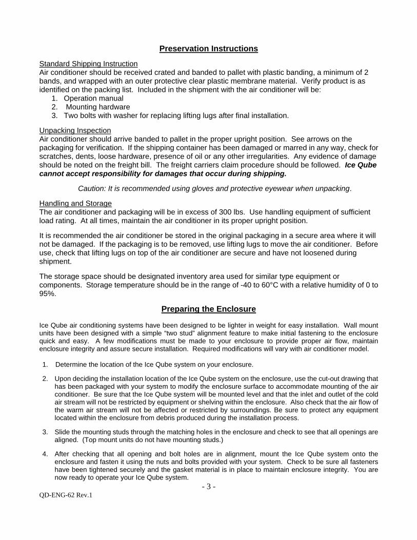
8. Models that require maintaining a positive purge pressure or closed loop will require fill of the condensate trap. Carefully and slowly pour 8.0 ounces (250 mL) of clean water into the drain pan located on rear of unit. Look for label marking. Some water may drain from the condensate overflow nipple on the side of the unit during this procedure. (FIG. 3)
9. Mechanical installation is complete. Continue with electrical connection.
Note: the evaporator compartment maintains a maximum IP66 rating while the condenser compartment is limited to IP65.

- 5 - QD-ENG-62 Rev.1
Figure 1 Alignment of ACU w/modified enclosure
Nylock Nut M10-1.25
M6 x 20MM Bolts (8)
Lifting Lugs
Mounting Studs

- 6 - QD-ENG-62 Rev.1
Figure 2 ACU installed on enclosure
- 7 - QD-ENG-62 Rev.1
Figure 3
Slowly pour 8.0 oz (250 mL) of water into drain pan to fill Ø5” (Ø127mm) loop.
There may be some water exiting the drain when filling.
Drain Loop

- 8 - QD-ENG-62 Rev.1
Electrical Installation Instruction
Please read the entire instruction before beginning the electrical connections to the ACU. Ice Qube air conditioners have been designed for easy electrical power connection at one location on the enclosure side of the air conditioner. The Air Conditioning Unit (ACU) components have been designed to operate at a range of voltage from 220 to 240 volts at 50 Hz.
***Warning: Electrical Shock and Explosion Hazard!*** Electrical connection should only be completed by a qualified technician. Compliance with all safety and electrical codes are required. Contact local authority having jurisdiction as required. Do not connect while the circuit is energized. Turn off circuit breaker and install lock out. The area is to be free of ignitable concentration of gases.
Pre-Installation Checks
1. Check ACU model label or specification for power requirements. 2. Check the designated ACU power supply for adequate and proper electrical power
requirements. 3. Check that wire routing to the ACU will not interfere with or become damaged by other
components.
Electrical Installation
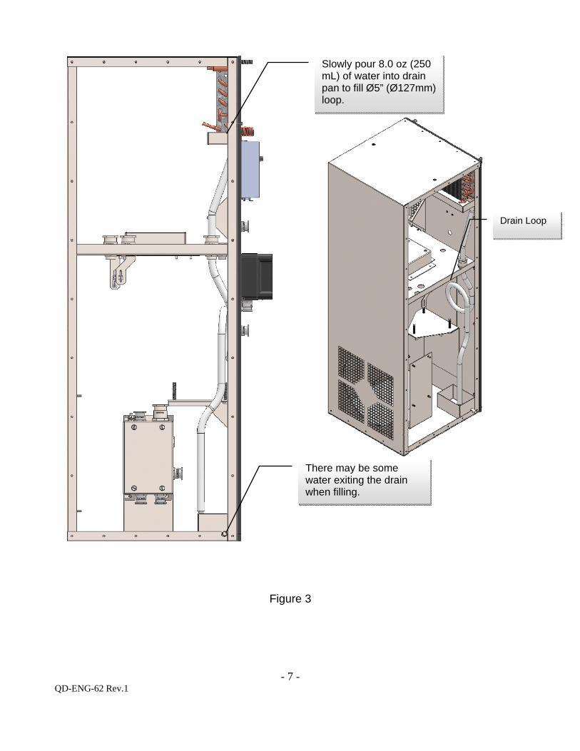
1. Check that ACU designated power supply is de-energized and locked out. 2. Locate Customer Interface electrical junction box on enclosure side of air conditioner. (FIG. 4) 3. Remove the four junction box cover bolts. Remove the cover, being careful not to damage the
cover perimeter gasket. (FIG. 5) 4. Loosen bottom nut of gland on the right side of the junction box to allow for power cable entry.
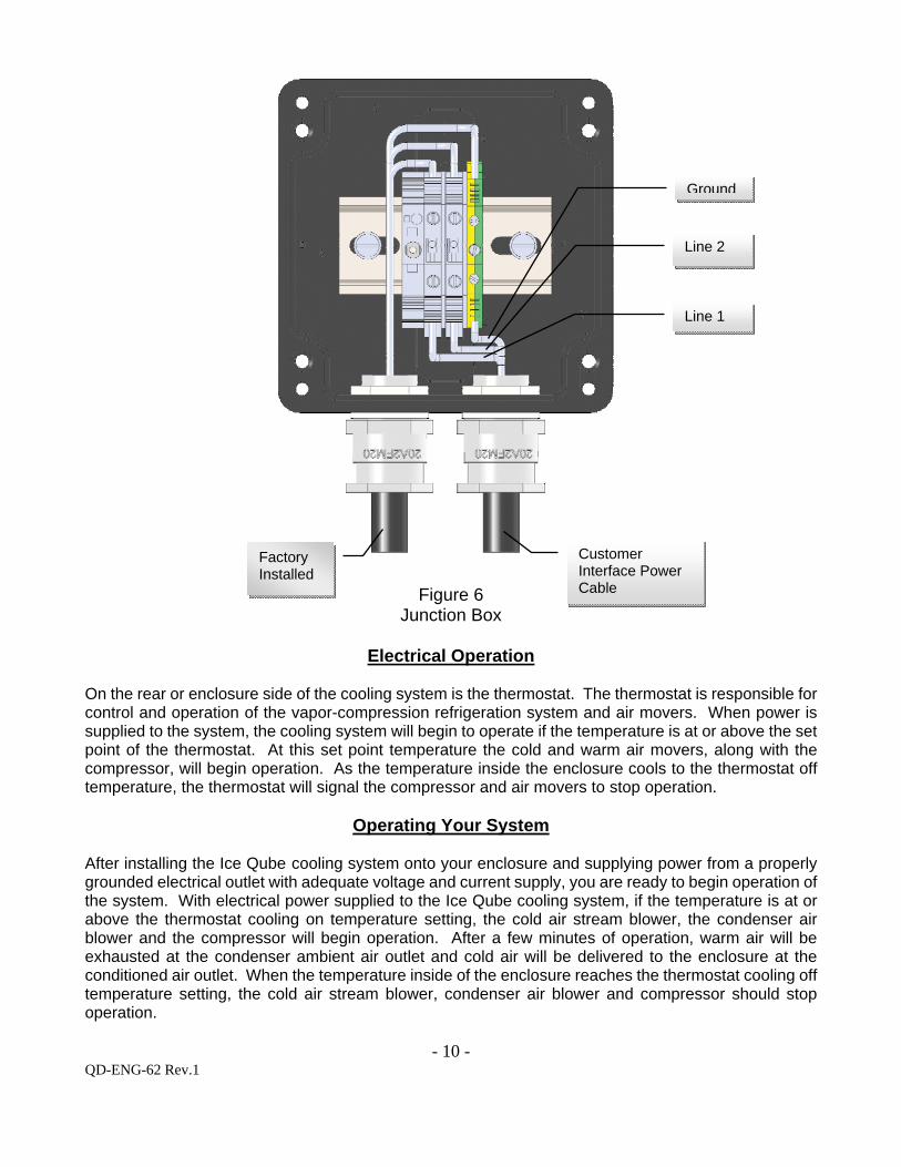
Power cable must be selected to meet power requirements of installed model and provide seal in the 20mm cable gland. Recommended conductor size is 4mm (12 gauge). (FIG. 6) Cable type should be a flexible conduit that is effectively clamped to prevent twisting and pulling.
5. Remove outer jacket from power cable to allow sufficient length of the three conductor wire for attachment to terminal blocks inside the junction box.
6. Strip inner jacket of the wires a length of 10mm. Remove any clear plastic coating. 7. Insert wires into the terminal blocks as shown, Line 1, Line 2 and Ground. After inserting wire,
tighten terminal block screws to 1.0 Nm (8.8 in-lbs). Check that wires are secure in terminal block and are connected to correct terminals.
Note: Two equipment ground studs with ring terminals are available, one near the customer interface and another near the flame proof enclosure.
8. Position power cable so that cable outer jacket will form seal in the cable gland. 9. Tighten bottom nut of gland until resistance is felt on the power cable. 10. Carefully position wires inside the junction box so they will not interfere with cover replacement. 11. Check that junction box gasket has not been damaged. Position junction box cover on the
junction box so that holes in box and cover are aligned. 12. Install the four junction bolts hand tight, then torque to 2.7 Nm (24 in-lbs) using a crossing
pattern. The system is now ready for operation.
- 9 - QD-ENG-62 Rev.1
Figure 4 Typical ACU enclosure Figure 5
Side view
Customer interface junction box
Cover Bolts (4)
- 10 - QD-ENG-62 Rev.1
Figure 6
Junction Box
Electrical Operation
On the rear or enclosure side of the cooling system is the thermostat. The thermostat is responsible for control and operation of the vapor-compression refrigeration system and air movers. When power is supplied to the system, the cooling system will begin to operate if the temperature is at or above the set point of the thermostat. At this set point temperature the cold and warm air movers, along with the compressor, will begin operation. As the temperature inside the enclosure cools to the thermostat off temperature, the thermostat will signal the compressor and air movers to stop operation.
Operating Your System
After installing the Ice Qube cooling system onto your enclosure and supplying power from a properly grounded electrical outlet with adequate voltage and current supply, you are ready to begin operation of the system. With electrical power supplied to the Ice Qube cooling system, if the temperature is at or above the thermostat cooling on temperature setting, the cold air stream blower, the condenser air blower and the compressor will begin operation. After a few minutes of operation, warm air will be exhausted at the condenser ambient air outlet and cold air will be delivered to the enclosure at the conditioned air outlet. When the temperature inside of the enclosure reaches the thermostat cooling off temperature setting, the cold air stream blower, condenser air blower and compressor should stop operation.
Factory Installed
Customer Interface Power Cable
Ground
Line 2
Line 1
- 11 - QD-ENG-62 Rev.1
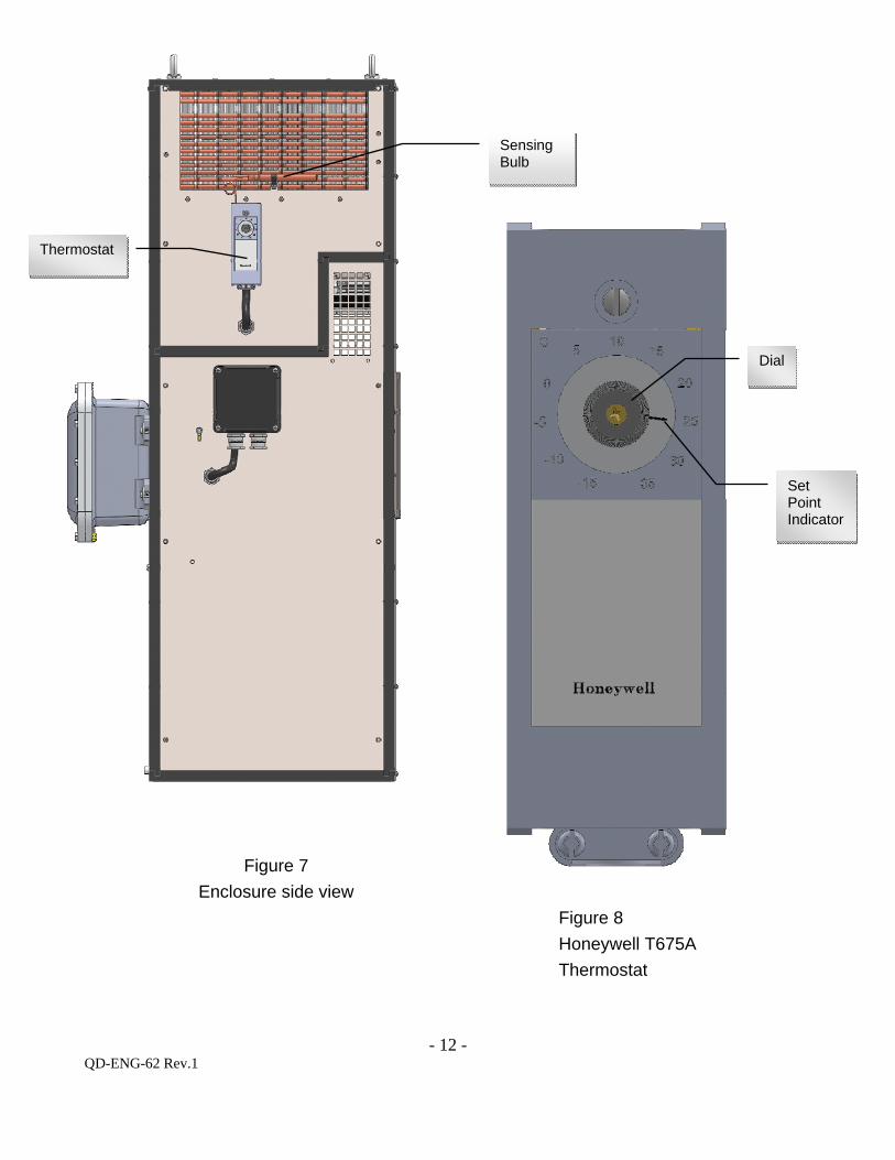
Operating the Cooling Thermostat The purpose of the thermostat (T675A) is to cycle on and off the cooling system as required from the heat produced by the equipment within the enclosure to prevent heat fatigue thus extending the life of the electronic equipment. The thermostat is located on the enclosure side of the air conditioner below the warm air return. The thermostat temperature sensing bulb is located in the warm stream of air returning to the air conditioner from the enclosure. On the face of the thermostat, you will see an adjustment knob within a temperature range of -15 to 35°C (5 to 95°F). To adjust the operating temperature of the thermostat, gently turn the knob until the pointer is aligned with the desired temperature of the enclosure. This is the temperature at which the cooling system will begin cooling. The thermostat has a factory set differential of 2.8°C (5°F). The unit will stop cooling when the enclosure temperature is 2.8°C (5°F) below the cooling on setting, indicated by the pointer. The unit will automatically begin to cool again when the internal temperature of the enclosure reaches the cooling on set point.
Ex: Set Point 25º C (77º F) Cooling on temperature 22.2º C (72º F) Cooling off temperature
Note: It is NOT recommended to set the controller at a set point below 20ºC (68ºF). Settings below this temperature may cause the evaporator coil to freeze.
Product complies with the following standards: IEC 60079-0:2011 IEC 60079-1:2007 IEC 60079-7:2006 IEC 60079-11:2011
EN 60079-0:2012 + A11:2013 EN 60079-1:2007 EN 60079-7:2007 EN 60079-11:2012
- 12 - QD-ENG-62 Rev.1
Figure 7
Enclosure side view
Figure 8
Honeywell T675A
Thermostat
Thermostat
Sensing Bulb
Dial
Set Point Indicator
- 13 - QD-ENG-62 Rev.1
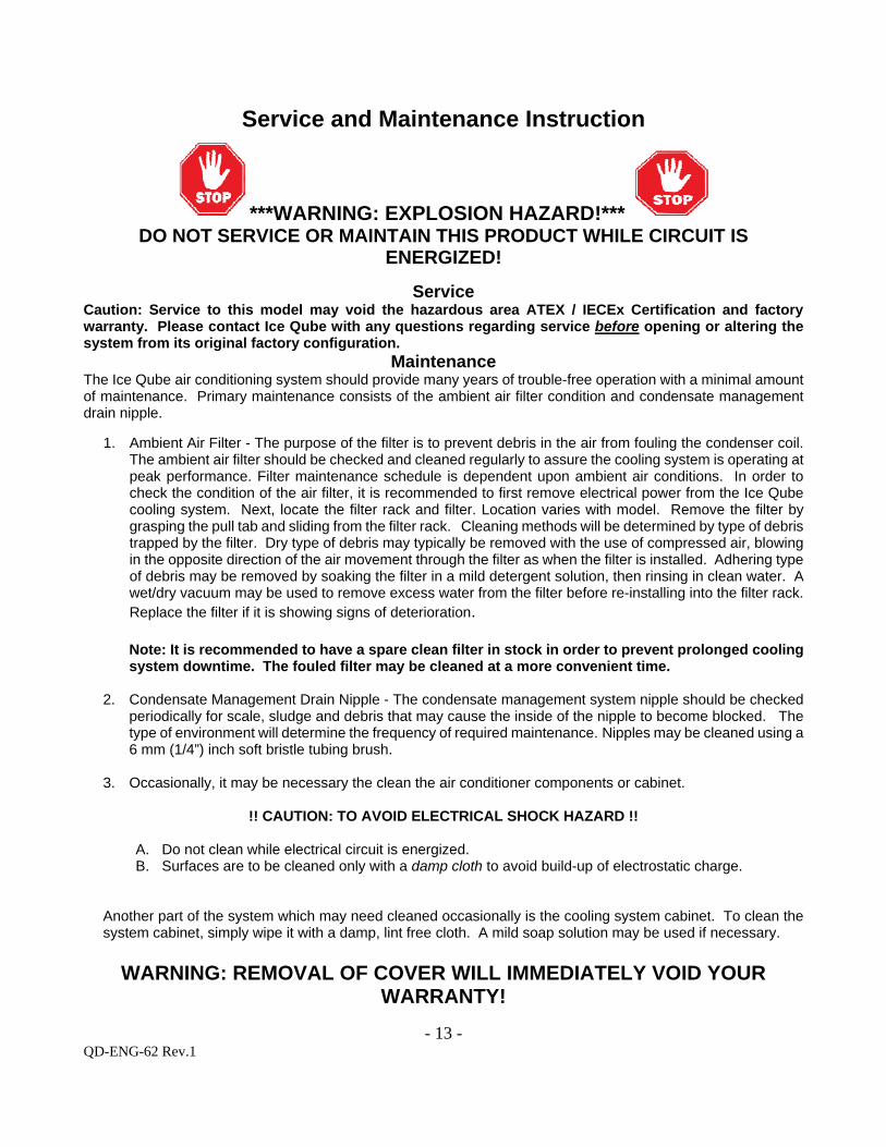
Service and Maintenance Instruction
***WARNING: EXPLOSION HAZARD!*** DO NOT SERVICE OR MAINTAIN THIS PRODUCT WHILE CIRCUIT IS
ENERGIZED!
Service Caution: Service to this model may void the hazardous area ATEX / IECEx Certification and factory warranty. Please contact Ice Qube with any questions regarding service before opening or altering the system from its original factory configuration.
Maintenance The Ice Qube air conditioning system should provide many years of trouble-free operation with a minimal amount of maintenance. Primary maintenance consists of the ambient air filter condition and condensate management drain nipple.
1. Ambient Air Filter - The purpose of the filter is to prevent debris in the air from fouling the condenser coil. The ambient air filter should be checked and cleaned regularly to assure the cooling system is operating at peak performance. Filter maintenance schedule is dependent upon ambient air conditions. In order to check the condition of the air filter, it is recommended to first remove electrical power from the Ice Qube cooling system. Next, locate the filter rack and filter. Location varies with model. Remove the filter by grasping the pull tab and sliding from the filter rack. Cleaning methods will be determined by type of debris trapped by the filter. Dry type of debris may typically be removed with the use of compressed air, blowing in the opposite direction of the air movement through the filter as when the filter is installed. Adhering type of debris may be removed by soaking the filter in a mild detergent solution, then rinsing in clean water. A wet/dry vacuum may be used to remove excess water from the filter before re-installing into the filter rack. Replace the filter if it is showing signs of deterioration. Note: It is recommended to have a spare clean filter in stock in order to prevent prolonged cooling system downtime. The fouled filter may be cleaned at a more convenient time.
2. Condensate Management Drain Nipple - The condensate management system nipple should be checked
periodically for scale, sludge and debris that may cause the inside of the nipple to become blocked. The type of environment will determine the frequency of required maintenance. Nipples may be cleaned using a 6 mm (1/4”) inch soft bristle tubing brush.
3. Occasionally, it may be necessary the clean the air conditioner components or cabinet.
!! CAUTION: TO AVOID ELECTRICAL SHOCK HAZARD !!
A. Do not clean while electrical circuit is energized. B. Surfaces are to be cleaned only with a damp cloth to avoid build-up of electrostatic charge.
Another part of the system which may need cleaned occasionally is the cooling system cabinet. To clean the system cabinet, simply wipe it with a damp, lint free cloth. A mild soap solution may be used if necessary.
WARNING: REMOVAL OF COVER WILL IMMEDIATELY VOID YOUR WARRANTY!
- 14 - QD-ENG-62 Rev.1
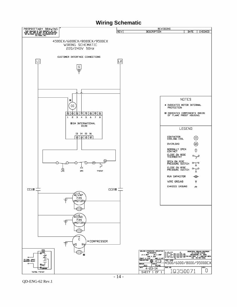
Wiring Schematic
- 15 - QD-ENG-62 Rev.1
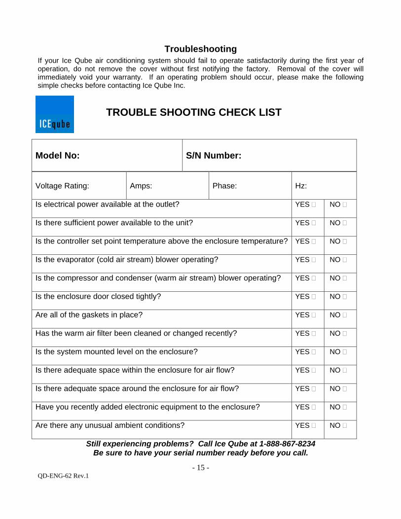
Troubleshooting
If your Ice Qube air conditioning system should fail to operate satisfactorily during the first year of operation, do not remove the cover without first notifying the factory. Removal of the cover will immediately void your warranty. If an operating problem should occur, please make the following simple checks before contacting Ice Qube Inc.
TROUBLE SHOOTING CHECK LIST
Model No:
S/N Number:
Voltage Rating:
Amps:
Phase:
Hz:
Is electrical power available at the outlet?
YES NO
Is there sufficient power available to the unit?
YES NO
Is the controller set point temperature above the enclosure temperature?
YES NO
Is the evaporator (cold air stream) blower operating?
YES NO
Is the compressor and condenser (warm air stream) blower operating?
YES NO
Is the enclosure door closed tightly?
YES NO
Are all of the gaskets in place?
YES NO
Has the warm air filter been cleaned or changed recently?
YES NO
Is the system mounted level on the enclosure?
YES NO
Is there adequate space within the enclosure for air flow?
YES NO
Is there adequate space around the enclosure for air flow?
YES NO
Have you recently added electronic equipment to the enclosure?
YES NO
Are there any unusual ambient conditions?
YES NO
Still experiencing problems? Call Ice Qube at 1-888-867-8234 Be sure to have your serial number ready before you call.
- 16 - QD-ENG-62 Rev.1
Standard Warranty Policy Ice Qube, Inc. ("Ice Qube") warrants that the products manufactured by Ice Qube (the "Products") are free of defects in material and workmanship which impair the operation of the Products, under normal and proper use and service, for a period of one (1) year from the date of shipment FCA from Ice Qube’s facility located in Greensburg, Pennsylvania (the "Standard Warranty"). In order for this Standard Warranty to apply, the Product(s) must be installed and operated according to and consistent with the following conditions:
Operation within the rated voltage on the label of the Product;
Frequency variation no greater than +/- 3 HZ from rated frequency on the label of the Product;
Ambient temperature must not exceed operating temperature range on the label of the Product;
Maximum cooling capacity not to exceed rating (BTU/HR) as rated on the label of the Product; and
The Product must be installed, maintained and operated consistent with the terms and conditions set forth in the operation manual. THIS STANDARD WARRANTY DOES NOT COVER THE FOLLOWING:
Ice Qube assumes no liability beyond the repair or replacement of its own Products. In no event shall Ice Qube be liable for any incidental, special, indirect, consequential or similar damages incurred by any purchaser, owner, possessor, assignee or successor in interest or any other third party having any interest in any Product as the result of any breach of this Standard Warranty, including but not limited to loss of profit or revenues, damages for loss of use of the Products, damage to property, both real and personal, claims of third parties, including personal injury or death on account of use of the Products or failure of Ice Qube to warn against or instruct on or adequately warn against or instruct on, the dangers of the Products or the safe and proper use of the Products, whether or not customer has been advised of the potential for such damages.
Ice Qube's total liability for customer's claims from any cause whatsoever, whether arising under contract, warranty, tort (including negligence), strict liability, products liability or any other theory of liability, will be limited to the lesser of customer's actual damages or the price paid by customer to Ice Qube for the Products (not including applicable taxes, duties and freight charges) that are the subject of customer's claim.
THE WARRANTY SET FORTH HEREIN IS STRICTLY LIMITED TO ITS TERMS AND IS IN LIEU OF ALL OTHER WARRANTIES, GUARANTEES, EXPRESS OR IMPLIED, ARISING BY OPERATION OF LAW, COURSE OF DEALING, CUSTOM, USAGE OF TRADE OR OTHERWISE, SPECIFICALLY EXCLUDING ANY IMPLIED WARRANTIES OF MERCHANTABILITY OR FITNESS FOR A PARTICULAR PURPOSE OR USE.
1. The warranty and remedies for breach of warranty provided for in this Standard Warranty extend only to the original installation and do not
cover, and Ice Qube will neither assume responsibility, nor be liable, for the following:
misapplication of its Products or the erroneous selection of an inappropriate Product by a non-authorized Ice Qube representative;
use of the Product for other than its designed purpose or operating conditions;
operation or storage in harsh, oily, corrosive or other abnormal environments without the proper filtration, sealing, protective coatings and/or weather protection;
damage to the hermetic system resulting from continuous operation with dirty or clogged air filters or improper or negligent maintenance;
use of refrigerant other than designated on the label of the Product;
customer modification or abuse;
shipping damage or other accidental damage (It is Ice Qube’s standard policy that freight claims are the responsibility of the customer if the Product is not refused at delivery);
repair, damage or service of the Product caused by anyone except personnel authorized by Ice Qube;
cracked or broken hermetic tubing, brazed joints or other internal damage caused by shipping or mishandling;
damage caused by shipping units attached to an enclosure;
any and all damage, breakage, malfunction or other like conditions or defects resulting from noncompliance with the standard operation, care, installation, maintenance and use of the Product as set forth in the operation manual for such Product;
any cause beyond the control of Ice Qube, including without limitation conditions caused by movement, settlement or structural defects of the environment in which the Products are installed;
- 17 - QD-ENG-62 Rev.1
fire, wind, hail, flood, lightning or other acts of God;
any damage to the finish of the Products after they leave Ice Qube's facility;
any discoloration or spotty appearance of the Products;
return freight and shipping charges, along with applicable duties and other like fees and charges, for the return of the Product to Ice Qube (such amounts are the sole responsibility of the customer);
failure to process or inaccurate processing of time-sensitive information and/or mechanisms; or
Exposure to harmful chemicals, pollutants or other foreign matter or energy. 2. All returns must have a RMA number and must be marked with the RMA number on the bill of lading and on the packaging.
3. Upon resale, customer agrees to extend to its customers no greater warranties, and limit its liability and remedies to the same extent, as
those set forth herein.
4. All Product literature is for illustrative purposes only and does not contain a warranty of any kind.
5. Ice Qube's advice relating to the technical usage of the Products or the intellectual property rights of others, whether provided orally or in writing or through the provision of test results, is given in accordance with Ice Qube's best knowledge at that time, but shall at all times be deemed to be non-binding. Such advice does not relieve customer from the obligation, and customer accepts full responsibility, to confirm for itself the suitability of the Products for their intended purpose(s).
Remedies
Customer's sole and exclusive remedy, and Ice Qube's only obligation for breach of warranty hereunder shall be, at Ice Qube's option, in its sole discretion, to (i) repair or replace the defective Product which fails within the one (1) year warranty period, free of charge, provided that customer promptly notifies Ice Qube of such failure and, after receipt of prior written authorization and return authorization number from Ice Qube, which will be given or withheld at Ice Qube's sole discretion, returns such Product to Ice Qube, Inc., 141 Wilson Avenue, Greensburg, PA 15601, USA or such other place as requested by Ice Qube, freight prepaid, and thereupon Ice Qube finds such to be defective or (ii) issue a credit equal to the price of the defective Product which fails within the one (1) year warranty period. Customer must pay all related costs of repair or replacement, including removal, installation or reinstallation costs. Ice Qube's personnel must be granted access to inspect the Products claimed to be defective at the site of their installation or use. Products repaired or replaced and designs corrected under this Standard Warranty are warranted only for the remainder of the original warranty period.