zoomlocktm flame-free refrigerant fittings · c. zoomlock fittings cannot be assembled using viega...
TRANSCRIPT

ZoomLockTM Flame-Free Refrigerant FittingsForm P-528, Engineering Specification, February 2018
FLAME-FREE REFRIGERANT FITTINGS

PART 1: GENERAL1.0 SUMMARY
A. ZoomLock flame-free refrigerant fittings are specially designed to join HVAC/R copper tubes without brazing. ZoomLock is intended for HVAC/R applications.
B. ZoomLock copper fittings include two pre installed o-rings. The system is assembled only using the Parker approved ZoomLock Klauke® or RIDGID® approved pressing jaws to create a permanent leak proof joint.
C. ZoomLock fittings cannot be assembled using Viega ProPress jaws. The installer shall be mindful that the crimp location of a ZoomLock fitting is in a different location than the ProPress fittings.
D. ZoomLock fittings and Klauke pressing tools and jaws are sold by your nearest authorized Parker Hannifin or Sporlan Division wholesaler.
E. ZoomLock RIDGID pressing jaws are sold by your nearest authorized Parker Hannifin or Sporlan Division wholesaler. RIDGID tools are sold by your nearest RIDGID authorized wholesaler.
PART 2: PRODUCTS2.0 REFERENCES
A. UL 207: Standard for Refrigerant-Containing Components and Accessories, Nonelectrical
B. UL 109: Standard for Tube Fittings for Flammable and Combustible Fluids, Refrigeration Services, and Marine Use. Vibration Test 8.1
C. ASME B31.5: Refrigeration Piping and Heat Transfer Components
D. ASTM B75: Standard Specification for Seamless Copper Tube
E. ASTM B88: Standard Specification for Seamless Copper Water Tube
F. ASTM B743: Standard Specification for Seamless Copper Tube in Coils
G. ASTM B280: Standard Specification for Seamless Copper Tube for Air Conditioning and Refrigeration Field Service
H. EN 12735-1: Copper and Copper Alloys. Seamless, round copper tubes for air conditioning and refrigeration. Tubes for piping systems
I. ASHRAE – 15: Safety Standard for Refrigeration Systems
J. ICC-ES, PMG-1296: Division 23 00 00-Heating, Ventilation and Air Conditioning
K. ICC: International Mechanical Code (IMC)
L. ICC: International Residential Code (IRC)
M. IAPMO: Uniform Mechanical Code (UMC)
N. CRN (Canadian Registration Number): #0A18303.5C
O. Parker Catalog K-1, ZoomLock Engineering Submittal
2.1 PRODUCT PARAMETERS
A. Applications: HVAC/R, Glycol and Non-Potable Water
B. Continuous Operating Temperature: 250°F (121°C)
C. O-Ring Temperature Rating: -40 to 300°F (-40 to 149°C)
D. Maximum Rated Pressure: 700 psi (48 bar)
E. Minimum Burst Pressure: 2,100 psi (145 bar)
F. Vacuum Pressure Capability: 20 micron
G. Maximum Leak Rate: 0.1 oz Helium per Year
H. Vibration Resistance: Conforms to UL 109
2.2 APPROVED REFRIGERANTS AND OILS
A. For the latest approved refrigerants refer to www.sporlanonline.com/ZoomLock
2.3 QUALITY ASSURANCE
A. All qualified installers shall be trained on the safe installation of ZoomLock flame-free refrigerant fittings. They should also be licensed within the jurisdiction.
B. ZoomLock fittings shall be installed using the proper tools and pressing jaws defined by the manufacturer.
C. Installation of HVAC/R copper tubing shall conform to the requirements of the International Mechanical and Residential Codes and Uniform Mechanical Code.
2.4 DELIVERY, STORAGE AND HANDLING
A. Do not stack boxes on top of ZoomLock fittings weighing more than 20 lbs.
B. When using a knife for unpacking, take special care not to scratch copper tubing or ZoomLock fittings since this can lead to leaks.
C. ZoomLock fittings and copper tubing shall be shipped to the job site in such a manner to protect the tubing and fittings. ZoomLock fittings and tubing shall not be roughly handled during shipment. Tubing and fittings shall be unloaded with reasonable care.
D. Protect the stored products from moisture, dirt and debris. Maintain elevated above grade. Do not exceed the structural capacity of the floor when stored inside.
2.5 PROJECT CONDITIONS
A. Allow the Klauke tool to reach ambient temperature if it is stored for prolonged periods of time at extreme temperatures. The ZoomLock Klauke tool’s operating temperature is 14° to 104°F. The RIDGID RP-200-B operating temperature is 15°F to 122°F and the RP-210-B operating temperature is 15°F to 140°F. Both RIDGID tools work with the Compact Series RIDGID jaws.
2.6 WARRANTY
A. ZoomLock fittings shall be free from defects in material and workmanship. The warranty shall only be applicable to the ZoomLock fittings installed in accordance with the installation instructions.
B. ZoomLock product warranty is maintained in Catalog K-1 ZoomLock Engineering Submittal.
Page 2 / ZoomLock Engineering Specification
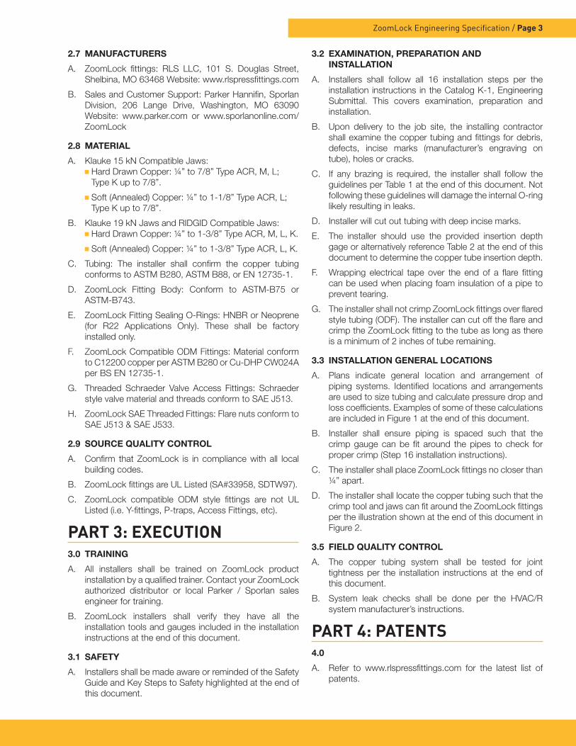
2.7 MANUFACTURERS
A. ZoomLock fittings: RLS LLC, 101 S. Douglas Street, Shelbina, MO 63468 Website: www.rlspressfittings.com
B. Sales and Customer Support: Parker Hannifin, Sporlan Division, 206 Lange Drive, Washington, MO 63090 Website: www.parker.com or www.sporlanonline.com/ZoomLock
2.8 MATERIAL
A. Klauke 15 kN Compatible Jaws: Hard Drawn Copper: ¼” to 7/8” Type ACR, M, L;
Type K up to 7/8”.
Soft (Annealed) Copper: ¼” to 1-1/8” Type ACR, L; Type K up to 7/8”.
B. Klauke 19 kN Jaws and RIDGID Compatible Jaws: Hard Drawn Copper: ¼” to 1-3/8” Type ACR, M, L, K.
Soft (Annealed) Copper: ¼” to 1-3/8” Type ACR, L, K.
C. Tubing: The installer shall confirm the copper tubing conforms to ASTM B280, ASTM B88, or EN 12735-1.
D. ZoomLock Fitting Body: Conform to ASTM-B75 or ASTM-B743.
E. ZoomLock Fitting Sealing O-Rings: HNBR or Neoprene (for R22 Applications Only). These shall be factory installed only.
F. ZoomLock Compatible ODM Fittings: Material conform to C12200 copper per ASTM B280 or Cu-DHP CW024A per BS EN 12735-1.
G. Threaded Schraeder Valve Access Fittings: Schraeder style valve material and threads conform to SAE J513.
H. ZoomLock SAE Threaded Fittings: Flare nuts conform to SAE J513 & SAE J533.
2.9 SOURCE QUALITY CONTROL
A. Confirm that ZoomLock is in compliance with all local building codes.
B. ZoomLock fittings are UL Listed (SA#33958, SDTW97).
C. ZoomLock compatible ODM style fittings are not UL Listed (i.e. Y-fittings, P-traps, Access Fittings, etc).
PART 3: EXECUTION3.0 TRAINING
A. All installers shall be trained on ZoomLock product installation by a qualified trainer. Contact your ZoomLock authorized distributor or local Parker / Sporlan sales engineer for training.
B. ZoomLock installers shall verify they have all the installation tools and gauges included in the installation instructions at the end of this document.
3.1 SAFETY
A. Installers shall be made aware or reminded of the Safety Guide and Key Steps to Safety highlighted at the end of this document.
3.2 EXAMINATION, PREPARATION AND INSTALLATION
A. Installers shall follow all 16 installation steps per the installation instructions in the Catalog K-1, Engineering Submittal. This covers examination, preparation and installation.
B. Upon delivery to the job site, the installing contractor shall examine the copper tubing and fittings for debris, defects, incise marks (manufacturer’s engraving on tube), holes or cracks.
C. If any brazing is required, the installer shall follow the guidelines per Table 1 at the end of this document. Not following these guidelines will damage the internal O-ring likely resulting in leaks.
D. Installer will cut out tubing with deep incise marks.
E. The installer should use the provided insertion depth gage or alternatively reference Table 2 at the end of this document to determine the copper tube insertion depth.
F. Wrapping electrical tape over the end of a flare fitting can be used when placing foam insulation of a pipe to prevent tearing.
G. The installer shall not crimp ZoomLock fittings over flared style tubing (ODF). The installer can cut off the flare and crimp the ZoomLock fitting to the tube as long as there is a minimum of 2 inches of tube remaining.
3.3 INSTALLATION GENERAL LOCATIONS
A. Plans indicate general location and arrangement of piping systems. Identified locations and arrangements are used to size tubing and calculate pressure drop and loss coefficients. Examples of some of these calculations are included in Figure 1 at the end of this document.
B. Installer shall ensure piping is spaced such that the crimp gauge can be fit around the pipes to check for proper crimp (Step 16 installation instructions).
C. The installer shall place ZoomLock fittings no closer than ¼” apart.
D. The installer shall locate the copper tubing such that the crimp tool and jaws can fit around the ZoomLock fittings per the illustration shown at the end of this document in Figure 2.
3.5 FIELD QUALITY CONTROL
A. The copper tubing system shall be tested for joint tightness per the installation instructions at the end of this document.
B. System leak checks shall be done per the HVAC/R system manufacturer’s instructions.
PART 4: PATENTS4.0
A. Refer to www.rlspressfittings.com for the latest list of patents.
ZoomLock Engineering Specification / Page 3

Page 4 / ZoomLock Engineering Specification
⚠WARNING – USER RESPONSIBILITYFailure or improper selection or improper use of the products described herein or related items can cause death, personal injury and property damage.
This document and other information from Parker Hannifin Corporation, its subsidiaries and authorized distributors provide product or system options for further investigation by users having technical expertise.
The user, through its own analysis and testing, is solely responsible for making the final selection of the system and components and assuring that all performance, endurance, maintenance, safety and warning requirements of the application are met. The user must analyze all aspects of the application, follow applicable industry standards, and follow the information concerning the product in the current product catalog and in any other materials provided from Parker or its subsidiaries or authorized distributors.
To the extent that Parker or its subsidiaries or authorized distributors provide component or system options based upon data or specifications provided by the user, the user is responsible for determining that such data and specifications are suitable and sufficient for all applications and reasonably foreseeable uses of the components or systems.
For safety information see the Safety Guide at www.parker.com/safety or call 1-800-CParker.
Crimp Bands
O-Ring FlangeO-Ring
KEY STEPS FOR SAFETY
Crimp Bands
O-Ring FlangeO-Ring
Crimp Bands
O-Ring FlangeO-Ring
Crimp Bands
O-Ring FlangeO-Ring
MARK TUBE DEPTH
CHECK TUBE DEPTH
CHECK FOR “RLS” MARK AFTER CRIMP
CHECK CRIMP WITH CRIMP GAUGE
BEFORE SELECTING OR USING ANY OF THESE PRODUCTS, IT IS IMPORTANT THAT YOU READ AND FOLLOW THE INSTALLATION INSTRUCTIONS.
• Fittings thrown off at high speed.
• High velocity fluid discharge.
• Explosion or burning of the conveyed fluid.
• Electrocution from high voltage electric power lines.
• Contact with suddenly moving or falling objects that are controlled by the conveyed fluid.
• Injections by high-pressure fluid discharge.
• Dangerously whipping copper line.
• Contact with conveyed fluids that may be hot, cold, toxic or otherwise injurious.
• Sparking or explosion caused by static electricity buildup or other sources of electricity.
• Sparking or explosion from flammable liquids.
FAILURE TO FOLLOW INSTALLATION INSTRUCTIONS, IMPROPER SELECTION OR IMPROPER USE OF ZOOMLOCK FITTINGS AND RELATED ACCESSORIES (“PRODUCTS”) CAN CAUSE DEATH, PERSONAL INJURY AND PROPERTY DAMAGE. POSSIBLE CONSEQUENCES OF FAILURE, IMPROPER SELECTION OR IMPROPER USE OF THESE PRODUCTS INCLUDE BUT ARE NOT LIMITED TO:
WARNING
PARKER SAFETY GUIDE FOR SELECTING AND USING ZoomLock FITTINGS AND RELATED ACCESSORIES
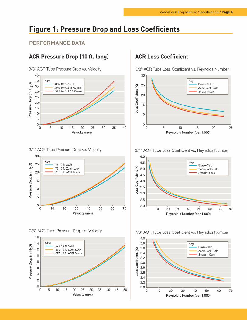
PERFORMANCE DATA
3/8” ACR Tube Pressure Drop vs. Velocity
0
5
10
15
20
25
30
35
40
45
0 5 10 15 20 25 30 35 40
Pre
ssur
e D
rop
(in.
H2O
)
Velocity (m/s)
Key:.375 10 ft. ACR .375 10 ft. ZoomLock .375 10 ft. ACR Braze
3/4” ACR Tube Pressure Drop vs. Velocity
0
5
10
15
25
20
30
0 10 20 30 40 50 60 70
Pre
ssur
e D
rop
(in.
H2O
)
Velocity (m/s)
Key:.75 10 ft. ACR .75 10 ft. ZoomLock .75 10 ft. ACR Braze
7/8” ACR Tube Pressure Drop vs. Velocity
0
2
14
12
10
8
6
4
16
0 5 10 15 2520 30 35 40 45 50
Pre
ssur
e D
rop
(in.
H2O
)
Velocity (m/s)
Key:.875 10 ft. ACR .875 10 ft. ZoomLock .875 10 ft. ACR Braze
3/8” ACR Tube Loss Coefficient vs. Reynolds Number
5
10
15
20
25
30
0 252015105
Loss
Co
effic
ient
(K)
Reynold’s Number (per 1,000)
Key:Braze-Calc ZoomLock-Calc Straight-Calc
3/4” ACR Tube Loss Coefficient vs. Reynolds Number
2.0
5.5
5.0
4.5
4.0
3.5
3.0
2.5
6.0
0 807060504010 20 30
Loss
Co
effic
ient
(K)
Reynold’s Number (per 1,000)
Key:Braze-Calc ZoomLock-Calc Straight-Calc
7/8” ACR Tube Loss Coefficient vs. Reynolds Number4.0
3.8
3.6
3.4
3.2
3.02.8
2.6
2.4
2.22.0
0 20 30 40 50 60 7010
Loss
Co
effic
ient
(K)
Reynold’s Number (per 1,000)
Key:Braze-Calc ZoomLock-Calc Straight-Calc
ACR Pressure Drop (10 ft. long) ACR Loss Coefficient
Figure 1: Pressure Drop and Loss Coefficients
ZoomLock Engineering Specification / Page 5

Table 1: Minimum Safe Distance to Braze from ZoomLock Fittings
Figure 2: Space Considerations Around ZoomLock Fittings
Table 2: Minimum Insertion Depth to Mark Tubing
Page 6 / ZoomLock Engineering Specification
MINIMUM DISTANCE FROM ZOOMLOCK FITTING TO BRAZE
Tube Diameter Inches Millimeters
1/4 to 1/2 5 127
5/8 7 178
3/4 8 203
7/8 9 229
1 9 229
1-1/8 11 279
1-3/8 14 356
MINIMUM INSERTION DEPTH
Fitting Size Inches Millimeters
1/4 1 24
5/16 1 24
3/8 1 24
1/2 1-1/4 32
5/8 1-1/4 32
3/4 1-1/4 32
7/8 1-1/4 32
1 1-1/4 32
1-1/8 1-1/4 32
1-3/8 1-1/2 38
The envelope of 11” x 7” is recommended around fittings. The illustration below shows closed space around the fitting with one end open. It assumes a 4” centerline between fittings and a max 1-3/8” couplings. A minimum of 2.25” from the back wall surface is required. You need 2-1/2” between couplings for jaws if the tool is coming up from below the fittings to crimp. We realize there are many configurations, so please contact your local Parker sales engineer with any questions.
7” Allow Room for Tool
11” Opening to Allow Room for Tool2.25” 4”
3”

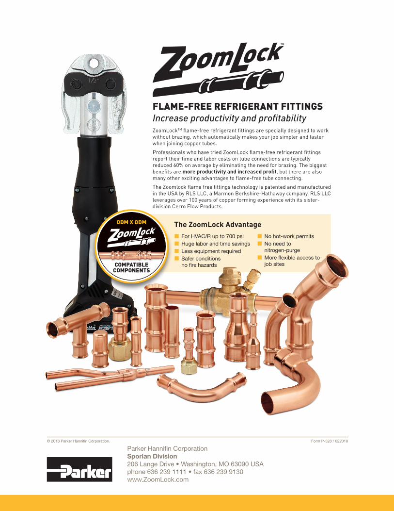
The ZoomLock Advantage
FLAME-FREE REFRIGERANT FITTINGSIncrease productivity and profitabilityZoomLockTM flame-free refrigerant fittings are specially designed to work without brazing, which automatically makes your job simpler and faster when joining copper tubes.
Professionals who have tried ZoomLock flame-free refrigerant fittings report their time and labor costs on tube connections are typically reduced 60% on average by eliminating the need for brazing. The biggest benefits are more productivity and increased profit, but there are also many other exciting advantages to flame-free tube connecting.
The Zoomlock flame free fittings technology is patented and manufactured in the USA by RLS LLC, a Marmon Berkshire-Hathaway company. RLS LLC leverages over 100 years of copper forming experience with its sister-division Cerro Flow Products.
■■ For HVAC/R up to 700 psi■■ Huge labor and time savings■■ Less equipment required■■ Safer conditions no fire hazards
■■ No hot-work permits■■ No need to nitrogen-purge■■ More flexible access to job sites
ODM X ODM
COMPATIBLECOMPONENTS
Parker Hannifin CorporationSporlan Division206 Lange Drive • Washington, MO 63090 USAphone 636 239 1111 • fax 636 239 9130www.ZoomLock.com
Form P-528 / 022018 © 2018 Parker Hannifin Corporation.