zs8a 2-wire telecontrol system - ees · zs8a 2-wire telecontrol system 28.06.2010 fw-zs8a-db-uk-003...
TRANSCRIPT
ZS8A 2-wire telecontrol system
FW-ZS8A-DB-UK-00328.0
6.20
10 Datenblatt
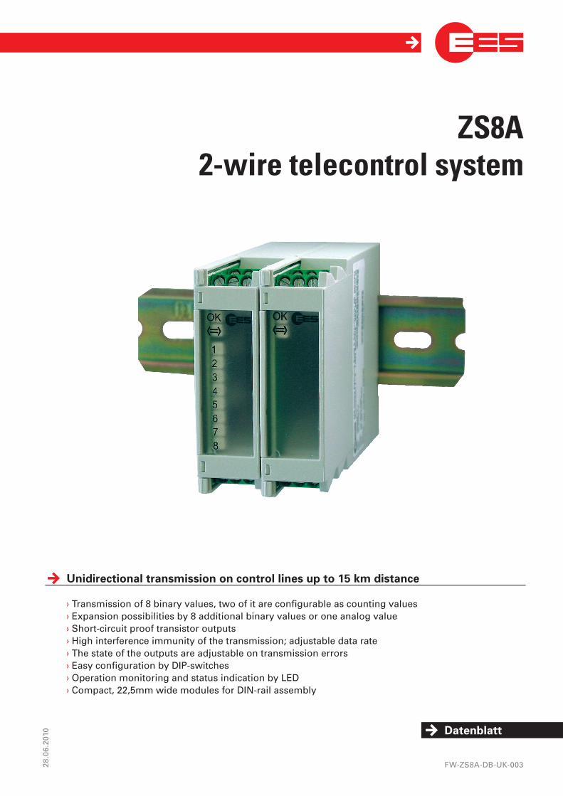
Unidirectionaltransmissiononcontrollinesupto15kmdistance
› Transmission of 8 binary values, two of it are configurable as counting values› Expansion possibilities by 8 additional binary values or one analog value› Short-circuit proof transistor outputs› High interference immunity of the transmission; adjustable data rate› The state of the outputs are adjustable on transmission errors› Easy configuration by DIP-switches› Operation monitoring and status indication by LED› Compact, 22,5mm wide modules for DIN-rail assembly
Page 2 of 8
ZS8A
Modeofoperation2-wiretransmission
The two-wire transmission system ZS8A was especially designed for cable-saving and immune to disturbance transmission of messages, commands and analog values over control lines with up to 15 km distance.The ZS8A system has no certain demand on the quality of the used cable for transmission, it has a high disturbance immunity against couplings from supply or signalling lines run in parallel. Therefore it is suitable for signal transmission in branched water / wastewater plants, industrial facilities and railway plants as well as building automation.
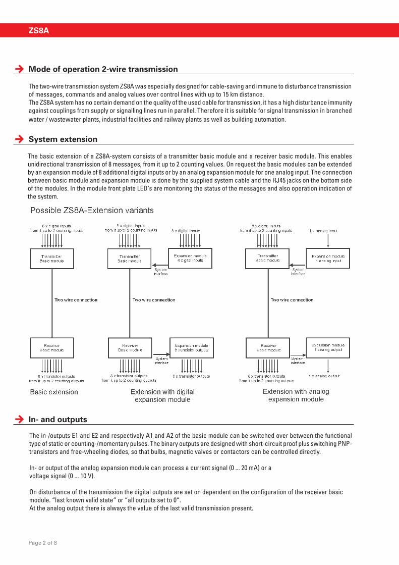
The basic extension of a ZS8A-system consists of a transmitter basic module and a receiver basic module. This enables unidirectional transmission of 8 messages, from it up to 2 counting values. On request the basic modules can be extended by an expansion module of 8 additional digital inputs or by an analog expansion module for one analog input. The connection between basic module and expansion module is done by the supplied system cable and the RJ45 jacks on the bottom side of the modules. In the module front plate LED‘s are monitoring the status of the messages and also operation indication of the system.
Systemextension
In-andoutputs
The in-/outputs E1 and E2 and respectively A1 and A2 of the basic module can be switched over between the functional type of static or counting-/momentary pulses. The binary outputs are designed with short-circuit proof plus switching PNP-transistors and free-wheeling diodes, so that bulbs, magnetic valves or contactors can be controlled directly.
In- or output of the analog expansion module can process a current signal (0 ... 20 mA) or avoltage signal (0 ... 10 V).
On disturbance of the transmission the digital outputs are set on dependent on the configuration of the receiver basic module. “last known valid state“ or “all outputs set to 0“.At the analog output there is always the value of the last valid transmission present.

Page 3 of 8
telecontrollIngoncontrollIneS
Modeofoperation2-wiretransmission
Every usual signal cable is suitable as transmission wire, in which the maximum loop restistance must not be exceeded. The bridgeable distance depends on the quality of the cable and the form and quantity of possibly noise interferences.
To adapt the ZS8A on the different application cases ( type of transmission cable, distance of transmission and the speed requirements for transmission ), the data transmission rate is adjustable by DIP-switches. With lower baud rates larger distances and higher immunity against disturbances can be achieved.
The data transmission of the ZS8A is done by digital telegrams coded with a checksum. The receiver module can safely recognize disturbed, faulty telegrams and also reject them. Possible disturbances result in a delayed transmission or interruption of the connection, but do not lead to falsified output values.
The ZS8A always transmits the actual state of the inputs at the time of inquiry. The minimum pulse width / pause, which is needed for a safe transmission of a change of state, depends on the actual set transmission baud rate (see table). For transmission of short pulses the inputs E1 and E2 and refering outputs A1 and A2 of the basic modules can be used for safe counting value transmission. Counting values are summed at the transmitter module until the next inquiry and transmitted as counter reading. The receiver module issues the difference of successive received counter readings in form of a pulse sequence, so that no counting pulses can be lost.
Duration of a transmission cycle in dependence of the set baud rateBaud rate [Baud] 1200 2400 4800 9600Distance of two telegrams [ms](Transmission cycle) 120 60 30 15
Minimum pulsewidth /-pause [ms]for the transmission of binary values 120 60 50 50
Note: The ZS8A-series is a further development of the approved previous ZS8-system. Both systems have identical terminal assignments and similar dimensions. However existing ZS8-modules can not be replaced through ZS8A-modules or be combined with them.

Page of 8
ZS8A
BlockdiagramoftheZS8A-modules

Page 5 of 8
telecontrollIngoncontrollIneS
terminalassignment
Term
inal
ZS8A-
GS8D
E
GS8D
A
EMG8
DE
EMG8
DA
EM1A
E
EM1A
A
1 L+ L+ L+2 L- L- L-3 2-wire A1 A14 C A2 C A25 E1 A3 E1 A36 E2 A4 E2 A47 E3 A5 E3 A58 E4 2-wire E49 E5 2-wire E510 E6 A6 E6 A6 GND GND11 E7 A7 E7 A7 0 ... 20 mA 0 ... 20 mA12 E8 A8 E8 A8 0 ... 10 V 0 ... 10 V
DIP-Switches
Top view
Bottom view
System bus-connector
Dimensions
Dimensions are validfor all ZS8A-modules
Dimensions in mm

Page 6 of 8
ZS8A
technicaldata
Nominal operating voltage UB 24 V DC
Operating voltage range 20 ... 32 V DC Power consumption at UB 24 V DC 32 V DC Transmitter basic module max. 1,0 W max. 1,3 W Expansion module digital input max. 0,4 W max. 0,4 W Expansion module analog input max. 0,3 W max. 0,4 W Receiver basic module max. 1,4 W max. 2,3 W + load current Expansion module digital output max. 1,4 W max. 2,3 W + load current Expansion module analog output max. 0,4 W max. 0,5 W
Digital inputsInput voltage 16 ... 35 V DC*Input resistance approx. 10 kΩmin. pulse width-/pause 50 msmax. count rate (basic module E1/E2) 10 Hz
Transistor outputsLoad on Transistor outputs max. 500 mA Total current of all outputs max. 1,6 APulse width -/pause (basic module A1/A2) 40 ms or 500 ms adjustableCounting rate (basic module A1/A2) 12,5 Hz or 1 Hz adjustable
Analog I/O Resolution 8 Bit Accuracy of the analog value Input signal +- 2 % of the scale Voltage signal 0 ... 10 V Input resistance 100 kΩ Minimum load resistance (output) 1 kΩ Current signal 0 ... 20 mA Current input burden 100 Ω Maximum output burden 500 Ω Galvanic isolation Insulation voltage (effective): Transmitter: Digital inputs against supply circuit 2,5 kV DC Receiver: 2-wire against supply circuit 2,5 kV DC
EM Compatibility Interference immunity DIN EN 61000-4-2:2001-12 DIN EN 61000-4-3:2008-06 DIN EN 61000-4-4:2005-07 DIN EN 61000-4-5:2007-06 DIN EN 61000-4-6:2008-04 DIN EN 61000-4-12:2007-08 Noise radiation DIN EN 61000-3-3:2006-06 DIN EN 55011:2007-11Signal transmission Two-wire level maximum UB / 25 mA Loop resistance maximum 10 kΩ Transmission rate (adjustable) 1200, 2400, 4800 or 9600 Baud
Page of 8
telecontrollIngoncontrollIneS
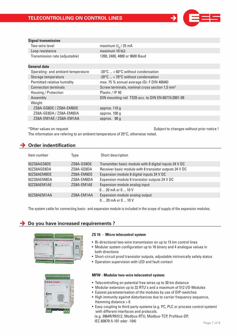
ZS 16 - Micro telecontrol system
• Bi-directional two-wire transmission on up to 15 km control lines• Modular system configuration up to 16 binary and 4 analogue values in both directions• Short-circuit proof transistor outputs, adjustable intrinsically safety status • Operation supervision with LED and fault contact
Doyouhaveincreasedrequirements?
orderindentification
Item number Type Short description
92ZS8AGS8DE ZS8A-GS8DE Transmitter basic module with 8 digital inputs 24 V DC92ZS8AGE8DA ZS8A-GE8DA Receiver basic module with 8 transistor outputs 24 V DC92ZS8AEM8DE ZS8A-EM8DE Expansion module 8 digital inputs 24 V DC 92ZS8AEM8DA ZS8A-EM8DA Expansion module 8 transistor outputs 24 V DC92ZS8AEM1AE ZS8A-EM1AE Expansion module analog input
0 ... 20 mA or 0 ... 10 V92ZS8AEM1AA ZS8A-EM1AA Expansion module analog output 0 ... 20 mA or 0 ... 10 V
The system cable for connecting basic- and expansion module is included in the scope of supply of the expansion modules.
MFW - Modular two-wire telecontrol system:
• Telecontrolling on potential free wires up to 30 km distance• Modular extension up to 32 RTU's and a maximum of 512 I/O-Modules• Easiest parameterisation of the modules by use of DIP-switches• High immunity against disturbances due to carrier frequency sequence, Hamming distance > 6• Easy coupling to third party systems (e.g. PC, PLC or process control system) with different interfaces and protocols. (e.g. 3964R/RK512, Modbus-RTU, Modbus-TCP, Profibus-DP, IEC 60870-5-101 oder -104)
Signal transmission Two-wire level maximum UB / 25 mA Loop resistance maximum 10 kΩ Transmission rate (adjustable) 1200, 2400, 4800 or 9600 Baud
General data Operating- and ambient temperature -20°C ... + 60°C without condensation Storage temperature -20°C ... + 70°C without condensation Permitted relative humidity max. 75 % annual average (Gr. F DIN 40040) Connection terminals Screw terminals, nominal cross section 1,5 mm2
Housing / Protection Plastic / IP 40 Assembly DIN mounting rail TS35 acc. to DIN EN 60715:2001-09 Weight ZS8A-GS8DE / ZS8A-EM8DE approx. 110 g ZS8A-GE8DA / ZS8A-EM8DA approx. 100 g ZS8A-EM1AE / ZS8A-EM1AA approx. 90 g
*Other values on request Subject to changes without prior notice !The information are refering to an ambient temperature of 25°C, otherwise noted.

contact
Elektra Elektronik GmbH & Co Störcontroller KG | Hummelbühl 7-9 | 71522 Backnang | GermanyTel. +49 (0) 7191.182-0 | Fax. +49 (0) 7191.182-200 | [email protected] | www.ees-online.de
Uninterruptible power supplies
CBS - Capacitor Backed 24 V power supply
• Broad input voltage 115 ... 230 V AC• Nominal output current 2 A• High life time: 30 years @ 30° Celsius • Maintenance-free by long-lasting ultra capacitors• Energy storage for 500 or 1000 J
PLG 60 - Accumulator buffered 24 V power supply
• Input voltage range 90 ... 264 V AC 127 ... 370 V DC• Output nominal current 1,25 A• Usable for lead and gel accumulators with capacities of 1.2 Ah up to 38 Ah• High efficiency by microcontroller supported loading and discharging of the accumulator• Higher accumulator life time by an optional temperature sensor
ZS8A2-wIretrAnSMISSIonSySteM
Power supplies
WSN 0,9/24 Wide range switching power supply
• Compact 22,5 mm thin power supply • Input voltage range nominal 100 ... 240 V AC 110 ... 220 V DC • Output voltage 24 V DC • Rated output current 0,9 A
WSN 60 Wide range switching power supply • Input voltage range nominal 90 .... 264 V AC • Output voltage 24 V DC • Rated output current 2,5 A
youwillfindasuitablepowersupplywithinouraccessoriesportfolio.