zssoldierpilewall - zsoil
TRANSCRIPT

ZSsoldierPileWall�A standalone module of ZSoil.PC 3Dfor soldier pile walls
USER GUIDEEdition 2019, 2019-08-06
ZACE Services Ltd. © 1985-2019
Zace Services Ltd, Software engineering
P.O.Box 2, CH-1015 Lausanne
Switzerland
(T) +41 21 802 46 05
(F) +41 21 802 46 06
http://www.zsoil.com,
hotline: [email protected]
since 1985

Contents
Table of Contents 1
ZSSOLDIERPILEWALL 1
1.1 OVERVIEW . . . . . . . . . . . . . . . . . . . . . . . . . . . . . . . . . . 1
1.2 FEATURES . . . . . . . . . . . . . . . . . . . . . . . . . . . . . . . . . . 2
1.3 MODELING SOIL BEHAVIOR . . . . . . . . . . . . . . . . . . . . . . . . . 3
1.3.1 Preconsolidation history . . . . . . . . . . . . . . . . . . . . . . . . 3
GETTING STARTED 5
2.1 GENERAL SETTINGS . . . . . . . . . . . . . . . . . . . . . . . . . . . . . 5
2.2 MAIN WINDOW . . . . . . . . . . . . . . . . . . . . . . . . . . . . . . . . 8
AUTOMATIC REPORTING 11
TUTORIALS 13
4.1 TUTORIAL 1 - ANCHORED SOLDIER PILE WALL . . . . . . . . . . . . . 13
4.1.1 Retaining system . . . . . . . . . . . . . . . . . . . . . . . . . . . . 15
4.1.2 Excavation stages . . . . . . . . . . . . . . . . . . . . . . . . . . . 19
4.1.3 Soil properties . . . . . . . . . . . . . . . . . . . . . . . . . . . . . 22
4.1.4 Boreholes . . . . . . . . . . . . . . . . . . . . . . . . . . . . . . . . 24
4.1.5 Running calculations . . . . . . . . . . . . . . . . . . . . . . . . . . 25
4.1.6 Automatic reporting . . . . . . . . . . . . . . . . . . . . . . . . . . 28
4.2 TUTORIAL 2 - EXCAVATION IN CLAYEY SOIL . . . . . . . . . . . . . . . 30
4.2.1 Retaining system . . . . . . . . . . . . . . . . . . . . . . . . . . . . 32
4.2.2 Excavation stages . . . . . . . . . . . . . . . . . . . . . . . . . . . 36
4.2.3 Soil properties . . . . . . . . . . . . . . . . . . . . . . . . . . . . . 39
4.2.4 Boreholes . . . . . . . . . . . . . . . . . . . . . . . . . . . . . . . . 41
4.2.5 Running calculations . . . . . . . . . . . . . . . . . . . . . . . . . . 42

4.2.6 Automatic reporting . . . . . . . . . . . . . . . . . . . . . . . . . . 45
APPENDICES 47
Appendix A.1: Automatic report for Tutorial 1 . . . . . . . . . . . . . . . . . . . 48
Appendix A.2: Automatic report for Tutorial 2 . . . . . . . . . . . . . . . . . . . 70
REFERENCES 93

ZSsoldierPileWall
ZSsoldierPileWall is a standalone application to analyze excavations protected by soldier pilewalls, based on the ZSOIL.PC 3D [7] FEM software. The program can alternatively be usedas a pre-preprocessing template within ZSoilr in order to speed-up data generation.
1.1 OVERVIEW
ZSsoldierPileWall� is a 3D FEM calculator basing on the ZSOIL.PC 3D software, designed tocarry out detailed analyses of excavations protected by soldier pile walls. It includes a coupledformulation for fully- and partially saturated two-phase media and advanced constitutive lawsfor soils. ZSsoldierPileWall� analyzes excavation sequences including intermediate stabilityand thermal expansion checks.
In addition ZSsoldierPileWall� 2019 offers:
• a user-friendly graphical interface
• simplified overall input strategy
• automated and user-configured, ready to print reporting
ZSsoldierPileWall� offers a variety of supporting systems which can be associated with exca-vations:
• soldier pile walls (piles with steel profiles, RC piles, steel profiles)
• tiebacks - anchors, nails
• internal bracing - struts
Finite element models which are generated by ZSsoldierPileWall� , can be opened with thestandard version of Z Soilr(*.inp file). This allows the models to be modified in order to an-alyze specific conditions which are not handled in the template, and then recalculated. More-over, results of the completed analyzes, can be visualized using the ZSoilr post-processor,whenever some specific outputs are requested.

ZSsoldierPileWall - USER GUIDE
Window 1-1: General view of the user interfaceZ Soil.PC
Window 1-1
1.2 FEATURES
ZSsoldierPileWall� offers the following capabilities:
• fast pre-processing of box-shaped excavations based on automatic finite element meshgeneration, including volumetric locking-free finite elements (eight node BBAR, EAS) andan advanced mesh tying technique used to connect dense (in the zone close to the retainingwall) and coarse (at a certain distance from the retaining wall) meshes with a very highlevel of accuracy
• modeling Soldier Piles (RC piles, full or partial length piles with embedded steel profiles,or steel profiles), lagging material (wood, concrete or any other), anchors, micropiles (asanchors with a very short free length), and struts
• accounting for surface loads
• advanced soil modeling using the Hardening-Soil model [4, 5], which is commonly recog-nized and accepted by the geotechnical community (refer to [3] for comprehensive descrip-tions on theory, parameter selection and examples of case studies). The model is extendedto account for strong stiffness variation in the range of small-strains [1].
• fully coupled (consolidation) or weakly coupled steady-state analyses including the effectsof partial saturation in soil (soil water retention curve model by van Genuchten [6]) - forthe theory, refer to [7].
• intermediate stability checks based on incremental tanφ− c reduction algorithm
2

1.3. MODELING SOIL BEHAVIOR
1.3 MODELING SOIL BEHAVIOR
In ZSsoldierPileWall� , soil behavior can be described by two commonly accepted constitutivemodels:
• [Hardening Soil model] (HS) - this model includes many macroscopic phenomena that areexhibited by soils for complex stress paths that are encountered during deep excavations.Therefore, it is highly recommended for simulation of excavation problems. In this model,the soil strength resistance is defined by the Mohr-Coulomb criterion.
• [Mohr-Coulomb] - this model has limited ability to reproduce soil behavior in serviceabilitystate analysis mainly due to unique, stress independent, stiffness modulus E which controlsloading and unloading stress paths. It can be useful for simple stability analyzes, but willnot accurately represent the deformations resulting from an excavation.
Both models require the definition of stiffness, strength and dilatancy, but the HS modelalso requires the effective stress history to be defined. This can be done by setting theoverconsolidation ratio (OCR) or preoverburden pressure (qPOP ). In the case of sands, atshallow depths, it is safe to assume OCR=1 or slightly above 1.0. For sandy layers placedbelow clayey layers one may assume similar level of overconsolidation as in clayey overlyinglayer. A detailed explanation of this matter is given in the foregoing subsection 1.3.1.
1.3.1 Preconsolidation history
The stress history in HS model can be defined in two ways:
• through the [Overconsolidation ratio] yielding a constant OCR profile:OCR = σvc/σ
′v0 where σvc is the vertical preconsolidation stress and σ′v0 denotes the
effective vertical stress.
• through the [Preoverburden pressure] yielding a variable OCR profile (OCR decreases withincreasing depth):qPOP = σvc − σ′v0
� The preoverburden pressure is useful to describe a varying OCR profile for superficiallayers of natural soils subject to mechanical overconsolidation or dessication.
With regards to the initial stress state, the coefficient of in− situ earth pressure at rest canbe defined ([Initial Ko State]) with the following methods:
• Manual
• Automatic if on �X[Auto evaluation K0]
[Auto evaluation K0] uses the commonly applied relationship from [2], which implies that K0
in natural soils increases with overconsolidation:
K0 = KNC0 OCRsinφ′ (1.1)
171201 3

ZSsoldierPileWall - USER GUIDE
The maximal admissible value of K0 is limited by the coefficient of passive earth pressure Kp:
Kp = tan2
(45o +
φ
2
)=
1 + sinφ
1− sinφ(1.2)
Window 1-2: Preconsolidation history and resulting K0 profile for given qPOP
Z Soil.PC
Window 1-2
4

GETTING STARTED
2.1 GENERAL SETTINGS
The application starts with the General settings dialog which enables one to select type ofthe predefined soldier pile wall technology (soldier beam as RC pile, full/partial length pilewith a steel profile or steel profile only), elements of the supporting system (anchors and/orstruts), fully coupled or steady state driver to carry out the analysis in the real time with arequested FE mesh density.
The General settings dialog box can be invoked at any time from the main toolbar Settingsof ZSsoldierPileWall� .
Window 2-1: Preselection of project settings
Z Soil.PC
Window 2-1

ZSsoldierPileWall - USER GUIDE
The setup components of General settings are as follows:
Wall type defines soldier pile wall type (this is the only option available in this template)
Construction technology defines construction type of the soldier pile
• [RC pile] - soldier pile is constructed as a reinforced concrete pile
• [Concrete pile stiffened by a steel profile] - soldier pile is constructed as a concrete pilewith an embedded steel profile
• [Steel profile embedded in concrete pile] - soldier pile is constructed as a steel profileembedded in a concrete pile (constructed till the bottom of excavation)
• [Steel profile only] - soldier pile is constructed as a steel profile driven into soil
Supporting system enables one to select preferable supporting components to be used
• [Anchors] - tie-back elements that consist of a pre-stressed cable/bar (Free length), anda pressurized concrete bulb in the soil (Bonded length); the anchor’s bond length shouldbe placed behind the potential slip surface in the subsoil. For details see Section 4-7. NB.micropiles (possibly prestressed) can be modeled as anchors with a very short free length
• [Struts] - structural components designed to resist outward-facing support compressionwhich can be modeled using:
- [Rigid support] with an infinite Stiffness of the spring, i.e. k = ∞ (horizontal dis-placement blocked)
- [Fictitious spring] defined by Spring stiffness: k and Prestress force F0
Drainage conditions define type of analysis to be carried out during the numerical simula-tion of excavation.
• [Single-phase] - ignores the presence of the ground water in the soil; partial saturationeffect is not considered in the simulation. This analysis applies whenever [Ground watertable] is inactive in the selected borehole.
• [Two-phase Steady state] - deformations are uniquely determined from the stress ob-tained for a fully dissipated excess pore pressure field meaning that the analysis is time in-dependent (recommended for modeling excavations in highly-permeable soils, e.g. sandsand gravels). A partially-saturated soil effect (suction) can be obtained only above theground water table behind the wall whereas inside the trench null pressures are imposedat the soil surface at each excavation stage. The steady state analysis is available onlyif [Ground water table] is �Xin the active borehole.
• [Two-phase Consolidation] considers soil behavior that is strongly dependent on time,especially for clayey soils with low permeability. It accounts for undrained or partially-drained conditions that can develop behind the soldier pile wall, as well as partially-saturated zone at the bottom of the excavation (effect of high suction build up belowthe excavation bottom in low-permeable soils). Consolidation analysis is available onlyif the [Ground water table] option is �Xin the active borehole.
6

2.1. GENERAL SETTINGS
� Quasi-undrained conditions can be obtained in low permeable soils (k = 10−9 −10−11 [m/s]) by setting fictitiously short time durations of excavation stages, i.e. 1day. In such a case, the undrained shear strength Su will be obtained as a functionof the current stress magnitude, σ′ = (σ′v, σ
′h), effective strength parameters (friction
angle φ′, cohesion c).
FE mesh density enables one to adapt the density of the finite element mesh with respectto the geometry of the analyzed problem
• [Automatic]
• [Coarse]
• [Medium]
• [Fine]
� Use [Coarse] mesh for preliminary calculations.� Using [Fine] meshes for relatively large models may lead to long computation time.
171201 7
ZSsoldierPileWall - USER GUIDE
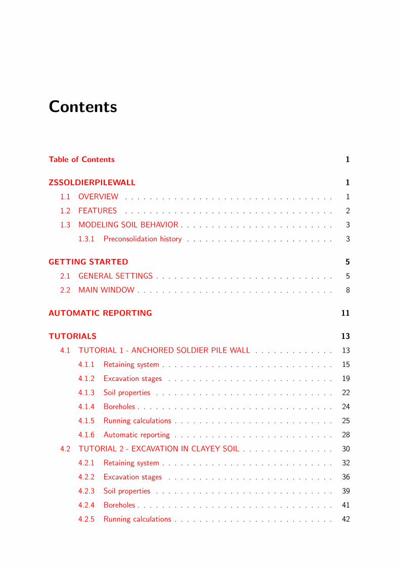
2.2 MAIN WINDOW
Window 2-2: Main screen of the application
Z Soil.PC
Window 2-2
TOP MENU consists of the following drop-down menus:
File : standard file operations such as [Open], [Save], [Save as]
� Project data are saved in *.inpw files and can easily be modified with a standard text editor.
Settings : enables one to set up general and detailed model components
- [General settings] (described already in section 2.1)
- [Detailed settings]
- [Type of analysis] ( [Single phase] / [Consolidation] / [Steady-state] )
- [Duration of excavation stages after wall installation]
- [Duration of consolidation after completing the excavation]
- [Number of computational steps for each excavation stage]
- [Mesh density] ( [Automatic] / [Coarse] / [Medium] / [Fine] )
To see an example please refer to Win. 4-2.
Subsoil : consists of three options
- [Materials] (to set up material data for subsoil layers)
- [Boreholes] (to set up boreholes stratigraphy; many boreholes may be defined, howeveronly one can be selected as active)
8

2.2. MAIN WINDOW
- [Import materials] (to import soil data from the standard ZSoil input files)
Run analysis : automatically generates the 3D FE model and runs the ZSoilr calculationmodule
Report : automatic and user-configured [Report content], ready to print reporting; theproject details, as well as the company logo can be specified in [Report Settings]
� By pressing [Run analysis], ZSsoldierPileWall� stores the data in the *.inpw fileand generates the finite element model which is saved in the standard ZSoilr format- *.inp file. It means that the model can be opened, modified, and recalculated withthe standard version of Z Soilr. Moreover, ZSoilr can be used anytime for datapost-processing if more demanding analyzes or graphical outputs are required.
Help : gives quick access to this User Guide
171201 9

ZSsoldierPileWall - USER GUIDE
MAIN SCREEN of the application (Win.2-2) consists of the following functional elementswhich allow the user to:
Borehole : define a set of boreholes, their coordinates and stratigraphy, ground water tablelevel in each borehole and select current active borehole; list of soil layers must be set firstin order to reuse them when editing borehole stratigraphy
Soldier pile wall : define soldier pile wall technology, geometry, material data for theselected soldier pile type and lagging
Loads : specify [Dead load] or [Live load] which will be acting on the terrain surface
� [Dead load] can be used to simulate moderately inclined terrain or an embankmentbehind the wall; therefore it exists already in the initial state, whereas [Live load] isgradually applied starting from the initial state until wall installation; it can be used tosimulate extra loading due to construction works.
+ Anchor : add new Anchors, tie-back support elements, and define their characteristics
+ Strut : add new Struts, outwards-facing support elements, and define their characteris-tics
+ Buttress : add and define characteristics of an outwards-facing elastic slab which isintroduced at the excavation bottom right behind the excavation front that advances inthe out-of-plane direction
Exc. : define the excavation depth
L : define height of the soldier pile
H , B1, B2: define horizontal dimensions of the model
Timeline : [STAGE: N] and duration of stages
Timeline slider : interactively previewing excavation stages
� EXC.END ÷ END stage is meaningful and visible only for [Consolidation] analysis.
10
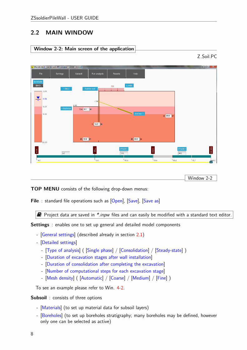
AUTOMATIC REPORTING
Results are synthesized in an automatically-generated report. The contents can easily beconfigured using the [Report content] dialog. The ready-to-print document consists of:
- the graphical representation of the geometry and the FE model
- general settings of the project including a summary of applied elements
- the properties of materials and members
- user-configured results, cf. Win. 3-2
Window 3-1: Report settings
Z Soil.PC
� Author, company name and its logo can be set up under [Results/Report settings]
� The resulting report header will look like
Window 3-1
ZSsoldierPileWall - USER GUIDE
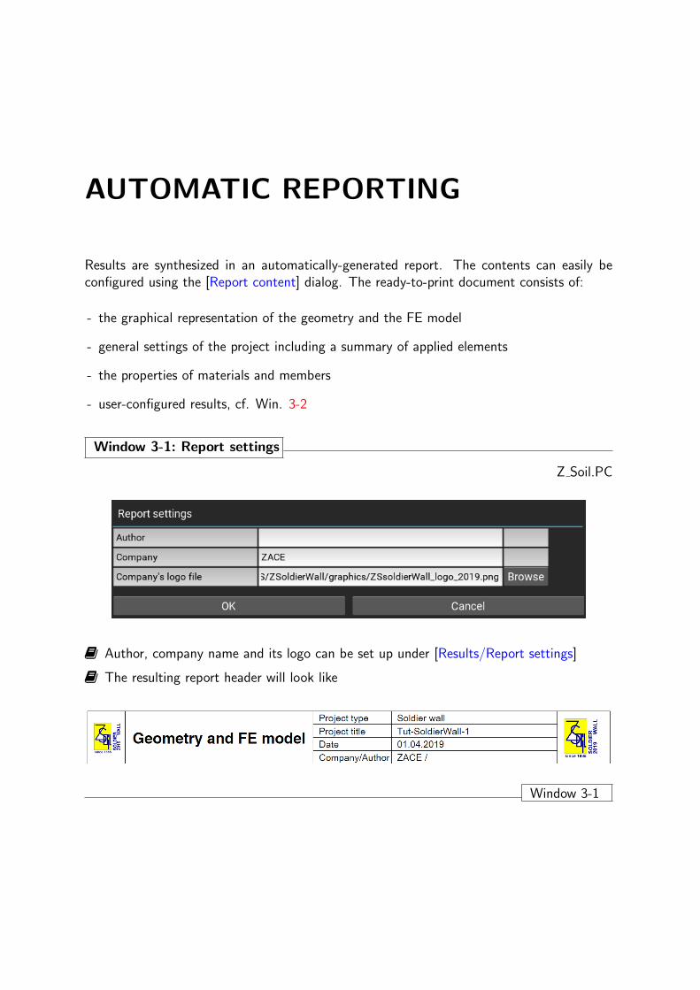
Window 3-2: Setting report content
Z Soil.PC
� Report content can be set up under [Results/Report content]
� Some options that are not meaningful are not considered
� It is recommended to print color maps of displacements and displacement vectors forpreliminary calculations in order to verify model kinematics, correctness of domain size(preferably null displacements in outer boundary elements), or length of tie-back supportelements (anchor’s bonded length outside of a potential slip surface), etc.
Window 3-2
12

TUTORIALS
4.1 TUTORIAL 1 - ANCHORED SOLDIER PILE WALL
Please open the first tutorial file via [File][Open tutorials]: TUT-SoldierWall-1.inpw
In this example, a 10m deep excavation problem in sandy subsoil is analyzed. The excavationis realized using an anchored soldier pile wall in which soldier piles are formed as ContinuousFlight Auger (CFA) reinforced concrete (RC) piles with wooden lagging. One row of pre-stressed anchors is installed at a depth 4m. Subsoil consists of two sandy layers (Sand 1 toa depth of 12m, then Sand2). As the water table is located below the excavation bottomand all sandy soil layers are highly permeable an uncoupled hydro-mechanical analysis is car-ried out. In this tutorial, the effect of strong soil stiffness variation in the regime of smallstrains is considered. The corresponding data without the small strain extension is kept inTUT-SoldierWall-1-HSstd.inpw file.
Window 4-1: Project setup
Z Soil.PC
� Assuming a central plane-of-symmetry (X-Z), half of the 30m wide trench is modeled
� The external boundaries of the model are put sufficiently far from the soldier pile wall toreduce their influence on the resulting sectional forces in the wall and its deformations, aswell as subsoil deformations.

ZSsoldierPileWall - USER GUIDE
Window 4-1
Window 4-2: General SettingsZ Soil.PC
� Here we define that the soldier pile is formed as RC pile while the supporting system mayconsist of anchors and/or struts (in the main screen buttons for both support types will bepresent). Mesh density is assumed as automatic and uncoupled two-phase analysis will becarried out.
Window 4-2
Window 4-3: Detailed SettingsZ Soil.PC
� In this window we define the duration of all excavation works. Other parameters are setalready in major settings and some of them (like impermeable barrier) are not considered.
Window 4-3
14

4.1. TUTORIAL 1 - ANCHORED SOLDIER PILE WALL
4.1.1 Retaining system
The retaining system consists of 12m long CFA RC piles (φ 60cm), installed with 2.5m spacing(see win.4-4 and 4-5), wooden lagging (see win.4-6) and one row of prestressed anchors forwhich the characteristics are presented in Win.4-7.
Window 4-4: Soldier pile wall technology
Z Soil.PC
A
� Here we can choose one of the possible constructions of soldier beams (RC pile, concretepile (full length) with an embedded steel profile, concrete pile (till bottom of excavation)with an embedded steel profile. steel profile only), length, spacing and installation absolutetime
� To select one of possible soldier pile wall types unroll combo-box A .
Window 4-4
171201 15

ZSsoldierPileWall - USER GUIDE
Window 4-5: Soldier pile characteristics
Z Soil.PC
A
� Here we define pile diameter, its unit weight, mechanical properties depending on theselected class of concrete
� To select proper concrete class unroll combo-box A ; mechanical properties are set upaccording to the EC2 standard
� It is possible to define user defined material
� Skin friction coefficient is computed as µ = Rint tanφ′ (φ′ is an effective soil friction
angle).
Window 4-5
16

4.1. TUTORIAL 1 - ANCHORED SOLDIER PILE WALL
Window 4-6: Lagging characteristics
Z Soil.PC
AB
� Here we define lagging material type (unroll combo-box A ) which can be wood, concreteor user defined. For selected wood or concrete class mechanical properties are set accordingto the standards (EC2).
� Lagging-soil interface friction coefficient is computed as µ = Rint tanφ′ (φ′ is an effective
soil friction angle).
Window 4-6
171201 17
ZSsoldierPileWall - USER GUIDE
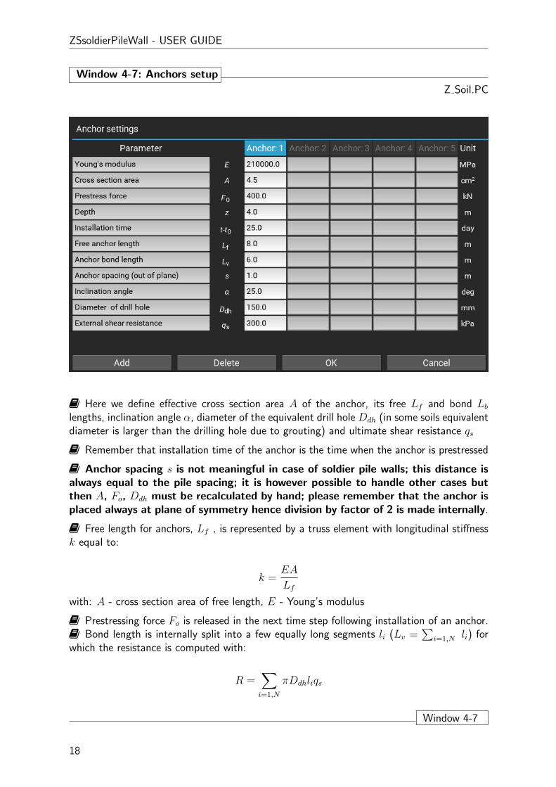
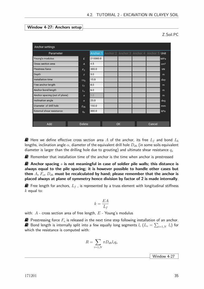
Window 4-7: Anchors setup
Z Soil.PC
� Here we define effective cross section area A of the anchor, its free Lf and bond Lblengths, inclination angle α, diameter of the equivalent drill hole Ddh (in some soils equivalentdiameter is larger than the drilling hole due to grouting) and ultimate shear resistance qs
� Remember that installation time of the anchor is the time when the anchor is prestressed
� Anchor spacing s is not meaningful in case of soldier pile walls; this distance isalways equal to the pile spacing; it is however possible to handle other cases butthen A, Fo, Ddh must be recalculated by hand; please remember that the anchor isplaced always at plane of symmetry hence division by factor of 2 is made internally.
� Free length for anchors, Lf , is represented by a truss element with longitudinal stiffnessk equal to:
k =EA
Lf
with: A - cross section area of free length, E - Young’s modulus
� Prestressing force Fo is released in the next time step following installation of an anchor.� Bond length is internally split into a few equally long segments li (Lv =
∑i=1,N li) for
which the resistance is computed with:
R =∑i=1,N
πDdhliqs
Window 4-7
18

4.1. TUTORIAL 1 - ANCHORED SOLDIER PILE WALL
4.1.2 Excavation stages
Window 4-8: Control of excavation stages
Z Soil.PC
A.1 A.1
-� endbeginning A.2
� Each intermediate construction stage can be configured by clicking [STAGE:N] button
( A.1 ) (see Win. 4-9 for more details)
� All construction sequences can be verified by moving the slider A.2 along time line (seeWin. 4-10).
Window 4-8
171201 19
ZSsoldierPileWall - USER GUIDE
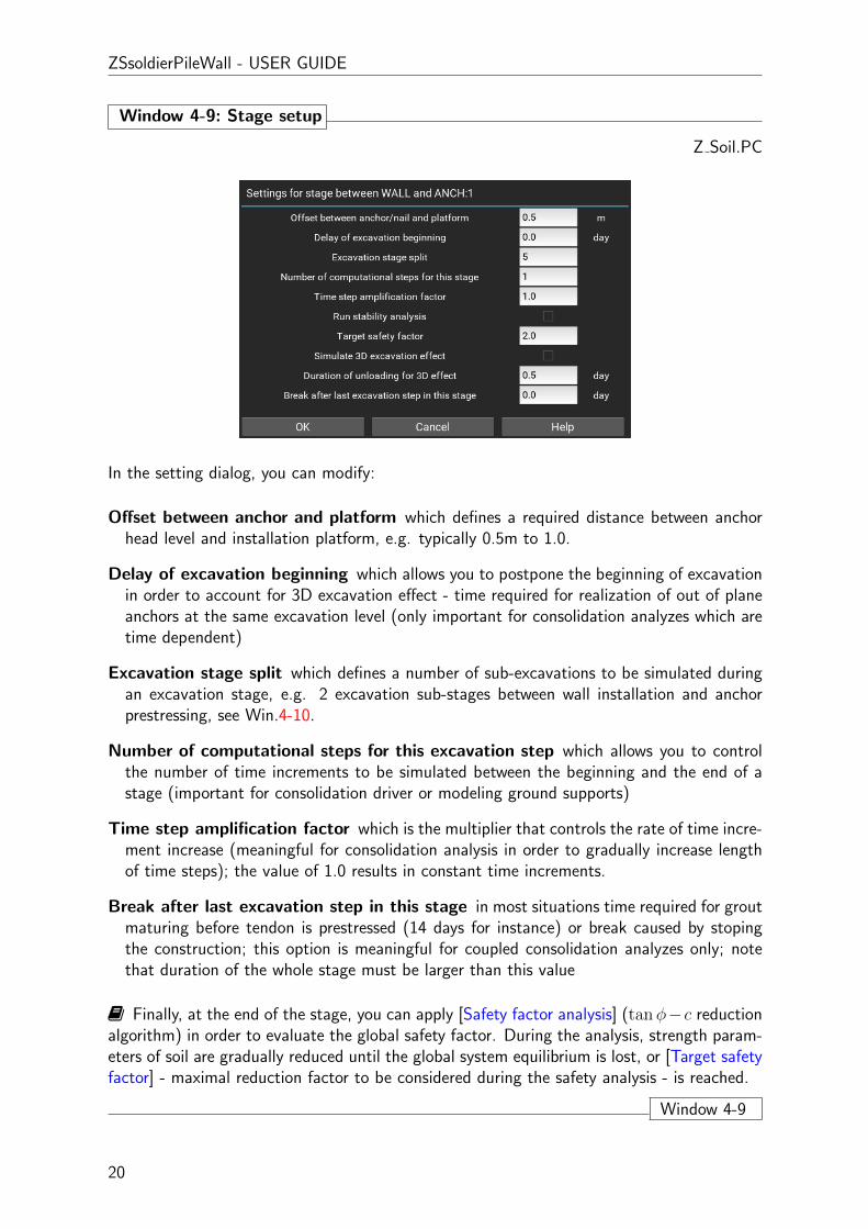
Window 4-9: Stage setup
Z Soil.PC
In the setting dialog, you can modify:
Offset between anchor and platform which defines a required distance between anchorhead level and installation platform, e.g. typically 0.5m to 1.0.
Delay of excavation beginning which allows you to postpone the beginning of excavationin order to account for 3D excavation effect - time required for realization of out of planeanchors at the same excavation level (only important for consolidation analyzes which aretime dependent)
Excavation stage split which defines a number of sub-excavations to be simulated duringan excavation stage, e.g. 2 excavation sub-stages between wall installation and anchorprestressing, see Win.4-10.
Number of computational steps for this excavation step which allows you to controlthe number of time increments to be simulated between the beginning and the end of astage (important for consolidation driver or modeling ground supports)
Time step amplification factor which is the multiplier that controls the rate of time incre-ment increase (meaningful for consolidation analysis in order to gradually increase lengthof time steps); the value of 1.0 results in constant time increments.
Break after last excavation step in this stage in most situations time required for groutmaturing before tendon is prestressed (14 days for instance) or break caused by stopingthe construction; this option is meaningful for coupled consolidation analyzes only; notethat duration of the whole stage must be larger than this value
� Finally, at the end of the stage, you can apply [Safety factor analysis] (tanφ−c reductionalgorithm) in order to evaluate the global safety factor. During the analysis, strength param-eters of soil are gradually reduced until the global system equilibrium is lost, or [Target safetyfactor] - maximal reduction factor to be considered during the safety analysis - is reached.
Window 4-9
20

4.1. TUTORIAL 1 - ANCHORED SOLDIER PILE WALL
Window 4-10: Preview of excavation stages
Z Soil.PC
-� endbeginning A.2
� Excavation stages can easily be previewed and verified by moving the bottom slider A.2- in the horizontal direction.
Window 4-10
171201 21
ZSsoldierPileWall - USER GUIDE
4.1.3 Soil properties
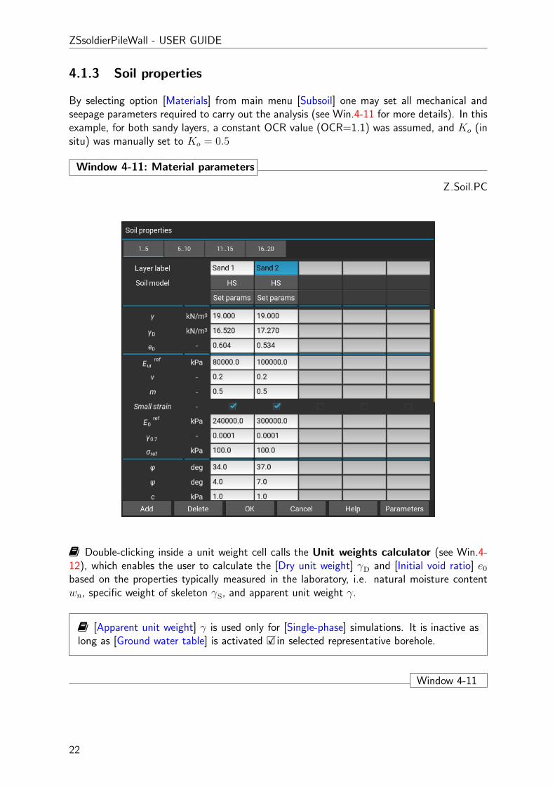
By selecting option [Materials] from main menu [Subsoil] one may set all mechanical andseepage parameters required to carry out the analysis (see Win.4-11 for more details). In thisexample, for both sandy layers, a constant OCR value (OCR=1.1) was assumed, and Ko (insitu) was manually set to Ko = 0.5
Window 4-11: Material parameters
Z Soil.PC
� Double-clicking inside a unit weight cell calls the Unit weights calculator (see Win.4-12), which enables the user to calculate the [Dry unit weight] γD and [Initial void ratio] e0based on the properties typically measured in the laboratory, i.e. natural moisture contentwn, specific weight of skeleton γS, and apparent unit weight γ.
� [Apparent unit weight] γ is used only for [Single-phase] simulations. It is inactive aslong as [Ground water table] is activated �Xin selected representative borehole.
Window 4-11
22
4.1. TUTORIAL 1 - ANCHORED SOLDIER PILE WALL
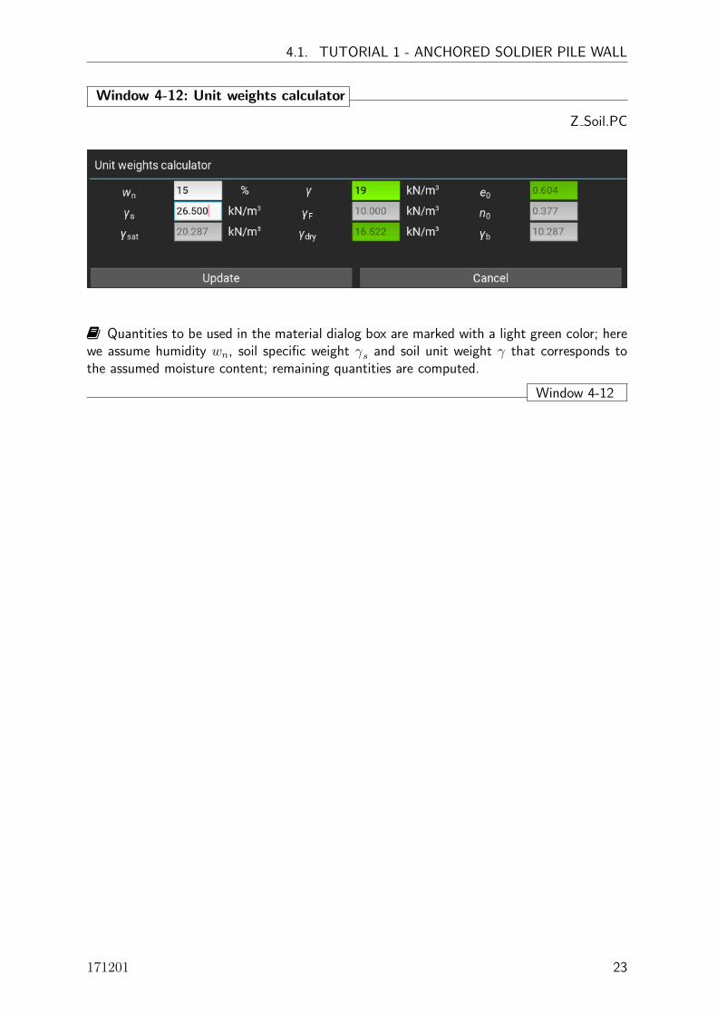
Window 4-12: Unit weights calculator
Z Soil.PC
� Quantities to be used in the material dialog box are marked with a light green color; herewe assume humidity wn, soil specific weight γs and soil unit weight γ that corresponds tothe assumed moisture content; remaining quantities are computed.
Window 4-12
171201 23

ZSsoldierPileWall - USER GUIDE
4.1.4 Boreholes
The Boreholes dialog enables the user to define a set of boreholes. However, only one ofthem can be selected as active in the foregoing computation. Each borehole is characterizedby its label, coordinates (not used so far), water level and subsoil stratigraphy. In this tutorialonly one borehole is defined (BH-0) with active water table set at depth 9m.
Window 4-13: Handling boreholes dataZ Soil.PC
• [New] - creates a new borehole sheet; once the data is complete press button [Add]; the[Add] action will add new borehole to the list
• [Add] - adds newly created borehole to the list (active exclusively after [New] action)
• [Update] - modifies data in the currently edited borehole
• [Delete] - removes current borehole
• [Insert], [Remove] - two actions available when editing stratification sheet ([Insert] addsnew row to the sheet above selected cell, [Remove] removes row with selected cell)
• [Status] - can be [Active] or [Inactive] for edited borehole; only one borehole can be setas active
• [Current borehole] - list of declared boreholes; the current borehole is shown in the cellnext to this text cell
� List of soil layers must be set first, otherwise it is impossible to set up borehole stratification
� By changing soil label under [Materials] borehole stratification may become undefined(user is warned in that case)
Window 4-13
24

4.1. TUTORIAL 1 - ANCHORED SOLDIER PILE WALL
4.1.5 Running calculations
Once the model is completed, calculations can be carried out. [Run analysis] automaticallygenerates the FE model (Win.4-14), and simulates construction/excavation steps using thegenuine ZSoilr calculation module.
Window 4-14: Automatically generated FE model
Z Soil.PC
� Stress and displacement compatibility between fine and coarse meshes of the FE modelare handled by a highly accurate mesh tying technique available within ZSoil module.
Window 4-14
171201 25

ZSsoldierPileWall - USER GUIDE
Window 4-15: Computation progress
Z Soil.PC
� Status of computation can be traced on the screen (see fig. above). In the case of a diver-gence for a given nonlinear solver, the calculation module automatically switches to anotheravailable solver (available solvers are: Newton-Raphson, BFGS, Initial Stiffness, AcceleratedInitial Stiffness).
� Nonlinear solver can manually be switched by the user using the button [Skip to nextnonl. solver], if the previous computation showed that the current solver is inefficient.
� In some difficult-to-converge cases, a modification of the tolerances for the right-hand side(TOL RHS) and energies (TOL E) can be made during computation (e.g. due to oscillations).However, it is not recommended to increase TOL RHS over 2%, or TOL E over 0.2%. Thisis recommended only for expert users.
Window 4-15
26

4.1. TUTORIAL 1 - ANCHORED SOLDIER PILE WALL
Window 4-16: Log of completed analysis
Z Soil.PC
� At the end of computation, an analysis log shows the computational status for eachexcavation macro stage. Typically, three status statements can be expected:
Computation completed which means that the system finished in equilibrium and compu-tation was successfully completed
Computation not completed due to divergence of computation (e.g. excessive soil/walldeformations or failure of anchor’s bond length)
Computation interrupted by the user if the computational module was stopped by theuser.
� In the summary of the analysis, you can configure the [Report content], or directly [Openreport]. For detailed automatic reporting refer to Section 2-2.
Window 4-16
171201 27

ZSsoldierPileWall - USER GUIDE
4.1.6 Automatic reporting
Window 4-17: Making the report
Z Soil.PC
� The report in pdf format is produced using option [Results/Open report]; this may take1 ÷ 2 minutes
� The automatic report produced for this first tutorial is given in Appendix 1.
� In addition, the Excel file labeled Tut-SoldierWall-1.xls is produced and contains en-velopes of sectional forces in the soldier piles (see Win.4-18).
Window 4-17
28

4.1. TUTORIAL 1 - ANCHORED SOLDIER PILE WALL
Window 4-18: Soldier beam envelopes in the xls format
Z Soil.PC
� Three sheets are produced; the first one contains the envelope of bending moments pluscorresponding axial and shear forces; the second contains the envelope of shear forces pluscorresponding bending moments and axial forces and the third one contains the envelope ofaxial forces plus corresponding bending moments and shear forces
Window 4-18
171201 29

ZSsoldierPileWall - USER GUIDE
4.2 TUTORIAL 2 - EXCAVATION IN CLAYEY SOIL
Please open the second tutorial file via [File][Open tutorials]: TUT-SoldierWall-2.inpw
In this example, a 6 m deep excavation in clayey subsoil is analyzed. The excavation isrealized using an anchored soldier pile wall in which soldier piles are formed as HEB 240 steelprofiles embedded in concrete piles (φ = 60 cm)(with spacing 2.2m) and wooden lagging.One row of prestressed anchors is installed at a depth of 3m. Subsoil consists of two layers(Sand 1 until a depth of 2m, then Clay 1). In order to obtain safe prediction we assume thatclayey layer is fully saturated and the initial pore water pressure is distributed hydrostaticalystarting from zero at a depth of 2m. As the clayey soil layer has a relatively low permeabilitythe consolidation analysis has to be carried out to reproduce properly the soil behavior. Inthis example time is a real parameter, therefore we have to carefully define duration of allconstruction stages.
Window 4-19: Project setup
Z Soil.PC
� Assuming a central plane-of-symmetry (X-Z), half of the 30m wide trench is modeled
� The external boundaries of the model are put sufficiently far from the soldier pile wall toreduce their influence on the resulting sectional forces, in the wall, and its deformations, aswell as subsoil deformations.
Window 4-19
30

4.2. TUTORIAL 2 - EXCAVATION IN CLAYEY SOIL
Window 4-20: General Settings
Z Soil.PC
� Here we define that the soldier pile is formed as a steel profile embedded in a concretepile (full length) while the supporting system may consist of anchors and/or struts (in themain screen buttons for both support types will be present). Mesh density is assumed asautomatic and two-phase consolidation analysis is to be carried out.� Seepage elements enabling the free outflow of water from clayey layer will automaticallybe defined on soil element faces being in contact with the wooden lagging (note that for lowpermeable soils outflow is negligible but pore pressure dissipation takes place)� If concrete or user defined lagging is defined, then the interface between the lagging andsubsoil is defined as impermeable (no seepage elements)
Window 4-20
Window 4-21: Detailed Settings
Z Soil.PC
171201 31

ZSsoldierPileWall - USER GUIDE
� In this window we define duration of all excavation works. Other parameters are setalready in major settings while some of them (like impermeable barrier) are not considered.� As the time is a real parameter, prior to anchor prestressing we need to wait until theanchor grout is sufficiently matured (14 days approximately)
Window 4-21
4.2.1 Retaining system
The retaining system consists of 9 m long EU HEB 240 steel profiles embedded in concretepiles (φ 60cm), installed with 2.2m spacing (see win.4-22 and 4-23), wooden lagging (seewin.4-26) and one row of prestressed anchors for which the characteristics are presented inWin.4-27.
Window 4-22: Soldier pile wall technology
Z Soil.PC
A
� Here we can choose one of the possible type of soldier piles (RC pile, concrete pile (fulllength) with an embedded steel profile, concrete pile (till bottom of excavation) with anembedded steel profile, steel profile only), length, spacing and installation time
� To select one of possible soldier pile wall types unroll combo-box A .
Window 4-22
32

4.2. TUTORIAL 2 - EXCAVATION IN CLAYEY SOIL
Window 4-23: Pile characteristics
Z Soil.PC
A
� Here we define pile diameter, its unit weight, mechanical properties depending on theselected class of concrete
� To select proper concrete class expand combo-box A ; mechanical properties are set upaccording to the EC2 standard
� It is possible to define user defined material
� Skin friction coefficient is computed as µ = Rint tanφ′ (φ′ is an effective soil friction
angle).
Window 4-23
Window 4-24: Characteristics of steel profile embedded in pile
Z Soil.PC
A
� Here we define steel profile to be embedded in pile (HEB 240 from EU data base)
� To select proper steel database and profile press buton A
� Skin friction coefficient is not meaningful in this case as profile is not in contact withsubsoil
Window 4-24
171201 33

ZSsoldierPileWall - USER GUIDE
Window 4-25: Selecting steel profile from databasesZ Soil.PC
ABCD
E
� Button A enables one to select steel profile from databases or custom setup
� In case of selecting steel profile from databases button B enables one to select one of
the predefined databases, button C selecting class of profiles while D selecting sectiondimensions; all profile geometrical characteristics are put in read only mode (grayed color) in
cells E
� In case of custom setup all geometrical characteristics must be defined in cells E
Window 4-25
Window 4-26: Lagging characteristicsZ Soil.PC
AB
� Here we define lagging material type (unroll combo-box A ) which can be wood, concreteor user defined. For selected wood or concrete class mechanical properties are set accordingto the standards (EC2).
� Lagging-soil interface friction coefficient is computed as µ = Rint tanφ′ (φ′ is an effective
soil friction angle).
Window 4-26
34
4.2. TUTORIAL 2 - EXCAVATION IN CLAYEY SOIL
Window 4-27: Anchors setup
Z Soil.PC
� Here we define effective cross section area A of the anchor, its free Lf and bond Lblengths, inclination angle α, diameter of the equivalent drill hole Ddh (in some soils equivalentdiameter is larger than the drilling hole due to grouting) and ultimate shear resistance qs
� Remember that installation time of the anchor is the time when anchor is prestressed
� Anchor spacing s is not meaningful in case of soldier pile walls; this distance isalways equal to the pile spacing; it is however possible to handle other cases butthen A, Fo, Ddh must be recalculated by hand; please remember that the anchor isplaced always at plane of symmetry hence division by factor of 2 is made internally.
� Free length for anchors, Lf , is represented by a truss element with longitudinal stiffnessk equal to:
k =EA
Lf
with: A - cross section area of free length, E - Young’s modulus
� Prestressing force Fo is released in the next time step following installation of an anchor.� Bond length is internally split into a few equally long segments li (Lv =
∑i=1,N li) for
which the resistance is computed with:
R =∑i=1,N
πDdhliqs
Window 4-27
171201 35

ZSsoldierPileWall - USER GUIDE
4.2.2 Excavation stages
Window 4-28: Control of excavation stages
Z Soil.PC
A.1 A.1
-� endbeginning A.2
� Each intermediate construction stage can be configured by clicking [STAGE:N] button
( A.1 ) (see Win. 4-29 for more details)
� All construction sequences can be verified by moving the slider A.2 along the timeline(see Win. 4-30)
� The gray zone in the timeline for STAGE:1 (t=6..20) means that for 14 days the excavationis stopped while anchor grout is in stage of maturing
� The next zone in the timeline for STAGE:2 (t=20..21) means that in this period of timeexcavation does not takes place and anchors prestressing is carried out
� At the end of all excavation steps, the analysis is continued for another 120 days; thisis important because deformations can still occur during this period due to pore pressuredissipation (forces in anchors are growing too)
Window 4-28
36

4.2. TUTORIAL 2 - EXCAVATION IN CLAYEY SOIL
Window 4-29: Stage setup
Z Soil.PC
In the setting dialog, you can modify:
Offset between anchor and platform which defines the required distance between theanchor head level and the installation platform, e.g. typically 0.5m to 1.0.
Delay of excavation beginning which allows you to postpone the beginning of the exca-vation in order to account for 3D excavation effect - time required for realization of outof plane anchors at the same excavation level (important for time dependent consolidationanalysis)
Excavation stage split which defines a number of sub-excavations to be simulated duringan excavation stage, e.g. 2 excavation sub-stages between wall installation and anchorprestressing, see Win.4-30.
Number of computational steps for this excavation step which allows you to controlthe number of time increments to be simulated between the beginning and the end of astage (important for consolidation driver or modeling ground supports)
Time step amplification factor which is the multiplier that controls the rate of time incre-ment increase (meaningful for consolidation analysis in order to gradually increase lengthof time steps); the value of 1.0 results in constant time increments.
Break after last excavation step in this stage in most situations time required for groutmaturing before tendon is prestressed (14 days for instance) or break caused by stopingthe construction; this option is meaningful for coupled consolidation analyzes only; notethat duration of the whole stage must be larger than this value
� Finally, at the end of the stage, you can apply [Safety factor analysis] (tanφ−c reductionalgorithm) in order to evaluate the global safety factor. During the analysis, strength param-eters of soil are gradually reduced until the global system equilibrium is lost, or [Target safetyfactor] - maximal reduction factor to be considered during the safety analysis - is reached.
Window 4-29
171201 37

ZSsoldierPileWall - USER GUIDE
Window 4-30: Preview of excavation stages
Z Soil.PC
-� endbeginning A.2
� Excavation stages can easily be previewed and verified by moving the bottom slider A.2- in the horizontal direction.
Window 4-30
38
4.2. TUTORIAL 2 - EXCAVATION IN CLAYEY SOIL
4.2.3 Soil properties
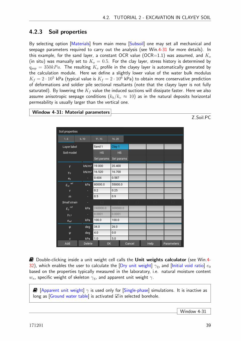
By selecting option [Materials] from main menu [Subsoil] one may set all mechanical andseepage parameters required to carry out the analysis (see Win.4-31 for more details). Inthis example, for the sand layer, a constant OCR value (OCR=1.1) was assumed, and Ko
(in situ) was manually set to Ko = 0.5. For the clay layer, stress history is determined byqpop = 350kPa. The resulting Ko profile in the clayey layer is automatically generated bythe calculation module. Here we define a slightly lower value of the water bulk modulusKf = 2 · 105 kPa (typical value is Kf = 2 · 106 kPa) to obtain more conservative predictionof deformations and soldier pile sectional resultants (note that the clayey layer is not fullysaturated). By lowering the Kf value the induced suctions will dissipate faster. Here we alsoassume anisotropic seepage conditions (kh/kv ≈ 10) as in the natural deposits horizontalpermeability is usually larger than the vertical one.
Window 4-31: Material parametersZ Soil.PC
� Double-clicking inside a unit weight cell calls the Unit weights calculator (see Win.4-32), which enables the user to calculate the [Dry unit weight] γD and [Initial void ratio] e0based on the properties typically measured in the laboratory, i.e. natural moisture contentwn, specific weight of skeleton γS, and apparent unit weight γ.
� [Apparent unit weight] γ is used only for [Single-phase] simulations. It is inactive aslong as [Ground water table] is activated �Xin selected borehole.
Window 4-31
171201 39

ZSsoldierPileWall - USER GUIDE
Window 4-32: Unit weights calculator
Z Soil.PC
� Quantities to be used in the material dialog box are marked with a light green color; herewe assume humidity wn, soil specific weight γs and soil unit weight γ that correspond to theassumed moisture content; remaining quantities are computed.
Window 4-32
40

4.2. TUTORIAL 2 - EXCAVATION IN CLAYEY SOIL
4.2.4 Boreholes
The Boreholes dialog enables the user to define a set of boreholes. However, only one ofthem can be selected as active in the foregoing computation. Each borehole is characterizedby its label, coordinates (not used so far), water level and subsoil stratigraphy. In this tutorialonly one borehole is defined (BH-0) with active water table set at depth 2 m.
Window 4-33: Handling boreholes dataZ Soil.PC
• [New] - creates a new borehole sheet; once the data is complete press button [Add]; the[Add] action will add new borehole to the list
• [Add] - adds newly created borehole to the list (active exclusively after [New] action)
• [Update] - modifies data in the currently edited borehole
• [Delete] - removes current borehole
• [Insert], [Remove] - two actions available when editing stratification sheet ([Insert] addsnew row to the sheet above selected cell, [Remove] removes row with selected cell)
• [Status] - can be [Active] or [Inactive] for edited borehole; only one borehole can be setas active so far
• [Current borehole] - list of declared boreholes; the current borehole is shown in the cellnext to this text cell
� List of soil layers must be set first, otherwise it is impossible to set up borehole stratification
� By changing soil label under [Materials] borehole stratification may become undefined(user is warned in that case)
Window 4-33
171201 41

ZSsoldierPileWall - USER GUIDE
4.2.5 Running calculations
Once the model is completed, calculations can be carried out. [Run analysis] automaticallygenerates the FE model (Win.4-34), and simulates construction/excavation steps using thegenuine ZSoilr calculation module.
Window 4-34: Automatically generated FE model
Z Soil.PC
� Stress and displacement compatibility between fine and coarse meshes of the FE modelare handled by a highly accurate mesh tying technique available within ZSoil module.
Window 4-34
42
4.2. TUTORIAL 2 - EXCAVATION IN CLAYEY SOIL
Window 4-35: Computation progress
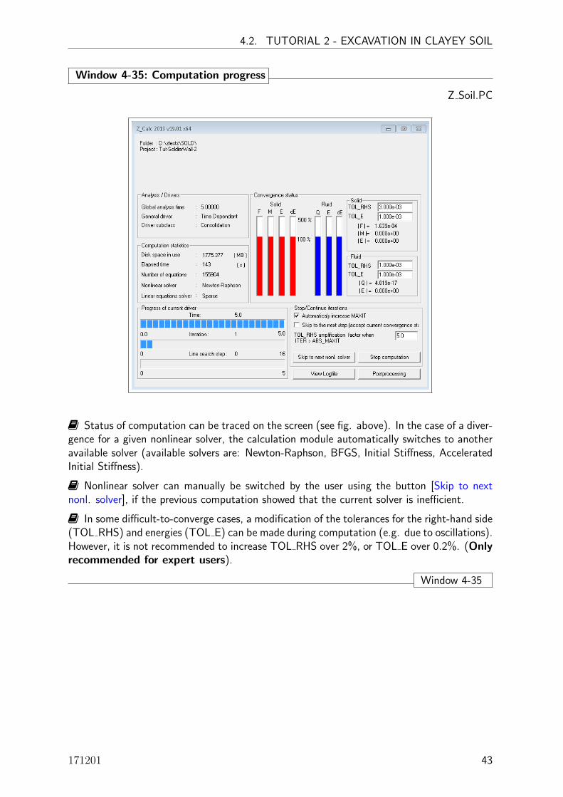
Z Soil.PC
� Status of computation can be traced on the screen (see fig. above). In the case of a diver-gence for a given nonlinear solver, the calculation module automatically switches to anotheravailable solver (available solvers are: Newton-Raphson, BFGS, Initial Stiffness, AcceleratedInitial Stiffness).
� Nonlinear solver can manually be switched by the user using the button [Skip to nextnonl. solver], if the previous computation showed that the current solver is inefficient.
� In some difficult-to-converge cases, a modification of the tolerances for the right-hand side(TOL RHS) and energies (TOL E) can be made during computation (e.g. due to oscillations).However, it is not recommended to increase TOL RHS over 2%, or TOL E over 0.2%. (Onlyrecommended for expert users).
Window 4-35
171201 43

ZSsoldierPileWall - USER GUIDE
Window 4-36: Log of completed analysis
Z Soil.PC
� At the end of the computation, an analysis log shows the computational status for eachexcavation macro stage. Typically, three status statements can be expected:
Computation completed which means that the system finished in equilibrium and compu-tation was successfully completed
Computation not completed due to divergence of the computation (e.g. excessive soil/walldeformations or failure of anchor’s bond length)
Computation interrupted by the user if the computational module was stopped by theuser.
� In the summary of the analysis, you can configure the [Report content], or directly [Openreport]. For detailed automatic reporting refer to Section 2-2.
Window 4-36
44

4.2. TUTORIAL 2 - EXCAVATION IN CLAYEY SOIL
4.2.6 Automatic reporting
Window 4-37: Making the report
Z Soil.PC
� The report in pdf format is produced using the option [Results/Open report]; this maytake 1 to 2 minutes
� The automatic report produced for this first tutorial is given in Appendix 1.
� In addition, the Excel file labeled Tut-SoldierWall-2.xls is produced and contains en-velopes of sectional forces in the soldier piles.
Window 4-37
171201 45

ZSsoldierPileWall - USER GUIDE
Window 4-38: Soldier beam envelopes in the xls format
Z Soil.PC
� Three sheets are produced; the first one contains the envelope of bending moments pluscorresponding axial and shear forces; the second contains the envelope of shear forces pluscorresponding bending moments and axial forces and the third one contains the envelope ofaxial forces plus corresponding bending moments and shear forces
Window 4-38
46

Appendices

ZSsoldierPileWall - USER GUIDE
Appendix A.1: Automatic report for Tutorial 1
48

Geometry and FE modelProject type Soldier pile wallProject title Tut-SoldierPileWall-1Date 06.08.2019Company/Author ZACE / Author
ZSsoldierPileWall - soldier pile wall (FE) calculator - v19.03 : Tut-SoldierPileWall-1.inpw v.19.03 Page 1
0.00m
12.00
20.00m
9.00
L=12.0m
Lf=8.0m, α=25⁰Lv=6.0m
Anchor 1: F₀=400kN
4.00
10kN/m²
H=2
0.0m
B₁=15.0m B₂=30.0m
8.0m
4.2. TUTORIAL 2 - EXCAVATION IN CLAYEY SOIL
171201 49

Wall and supportingsystem characteristics
Project type Soldier pile wallProject title Tut-SoldierPileWall-1Date 06.08.2019Company/Author ZACE / Author
ZSsoldierPileWall - soldier pile wall (FE) calculator - v19.03 : Tut-SoldierPileWall-1.inpw v.19.03 Page 2
Wall characteristicsProperty Symbol Unit Value
Detailed construction type Standard RC pile
Length L m 12.0
Spacing (out of plane) s m 2.5
Installation time t0
day 5.0
Profile(s)
Pile
Class of concrete - C20/25
Young's modulus E MPa 30000.0
Poisson's coefficient ν - 0.2
Diameter d cm 60.0
Unit weight γ kN/m3 24.0
Soil-pile interface friction coeff. ratio Rint
- 1.0
Lagging
Material type - Wood
Class of material - C22
Thickness t cm 10.0
Young's modulus E MPa 10000.0
Poisson's coefficient ν - 0.2
Unit weight γ kN/m3 4.1
Technological gap in soil-lagging interface gi
cm 0.0
Soil-lagging interface friction ratio Rint
- 0.6
AnchorsProperty Symbol Unit ANCHOR 1
Free anchor length Lf
m 8.0
Anchor bond length Lv
m 6.0
Depth z m 4.0
Young's modulus E MPa 210000.0
Cross section area A cm2 4.5
Prestress force F0
kN 400.0
Inclination angle α deg 25.0
Anchor spacing (out of plane) s m 1.0
Diameter of drill hole Ddh
mm 150.0
ZSsoldierPileWall - USER GUIDE
50

Wall and supportingsystem characteristics
Project type Soldier pile wallProject title Tut-SoldierPileWall-1Date 06.08.2019Company/Author ZACE / Author
ZSsoldierPileWall - soldier pile wall (FE) calculator - v19.03 : Tut-SoldierPileWall-1.inpw v.19.03 Page 3
Property Symbol Unit ANCHOR 1
External shear resistance qs
kPa 300.0
Installation time t-t0
day 25.0
4.2. TUTORIAL 2 - EXCAVATION IN CLAYEY SOIL
171201 51

General settingsProject type Soldier pile wallProject title Tut-SoldierPileWall-1Date 06.08.2019Company/Author ZACE / Author
ZSsoldierPileWall - soldier pile wall (FE) calculator - v19.03 : Tut-SoldierPileWall-1.inpw v.19.03 Page 4
Analysis settingsProperty Unit Value
Type of analysis Two-phase Steady state
Duration of excavation stages after wall installation [day] 50.0
Duration of consolidation after completing the excavation [day] 120.0
Number of computational steps for each excavation stage [-] 1
FE mesh density Automatic
ZSsoldierPileWall - USER GUIDE
52

Construction stagesProject type Soldier pile wallProject title Tut-SoldierPileWall-1Date 06.08.2019Company/Author ZACE / Author
ZSsoldierPileWall - soldier pile wall (FE) calculator - v19.03 : Tut-SoldierPileWall-1.inpw v.19.03 Page 5
IN SITU - WALL WALL - ANCH:1ANCH:1 -EXC.END
Analysis status Completed Completed Completed
Offset between anchor/nail and platform 0.5 [m]
Delay of excavation beginning 0.0 [day] 1.0 [day]
Excavation stage split 5 5
Number of computational steps for this stage 1 1
Time step amplification factor 1.0 1.0
Break after last excavation step in this stage 0.0 [day]
4.2. TUTORIAL 2 - EXCAVATION IN CLAYEY SOIL
171201 53
ZSsoldierPileWall - soldier pile wall (FE) calculator - v19.03 : Tut-SoldierPileWall-1.inpw v.19.03 Page 6
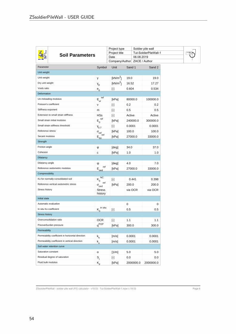
Soil ParametersProject type Soldier pile wallProject title Tut-SoldierPileWall-1Date 06.08.2019Company/Author ZACE / Author
Parameter Symbol Unit Sand 1 Sand 2
Unit weight
Unit weight γ [kN/m3] 19.0 19.0
Dry unit weight γD
[kN/m3] 16.52 17.27
Voids ratio e0
[-] 0.604 0.534
Deformation
Un-/reloading modulus Eur
ref [kPa] 80000.0 100000.0
Poisson's coefficient ν [-] 0.2 0.2
Stiffness exponent m [-] 0.5 0.5
Extension to small strain stiffness HSs [-] Active Active
Small strain initial modulus E0ref [kPa] 240000.0 300000.0
Small strain stiffness threshold γ0.7
[-] 0.0001 0.0001
Reference stress σref
[kPa] 100.0 100.0
Secant modulus E50
ref [kPa] 27000.0 33000.0
Strength
Friction angle φ [deg] 34.0 37.0
Cohesion c [kPa] 1.0 1.0
Dilatancy
Dilatancy angle ψ [deg] 4.0 7.0
Reference oedometric modulus Eoed
ref [kPa] 27000.0 33000.0
Compressibility
Ko for normally-consolidated soil K0NC [-] 0.441 0.398
Reference vertical oedometric stress σoed
ref [kPa] 200.0 200.0
Stress history Stresshistory
via OCR via OCR
Initial state
Automatic evaluation 0 0
In situ Ko coefficient K0in situ [-] 0.5 0.5
Stress history
Overconsolidation ratio OCR [-] 1.1 1.1
Preoverburden pressure qPOP [kPa] 300.0 300.0
Permeability
Permeability coefficient in horizontal direction kh
[m/s] 0.0001 0.0001
Permeability coefficient in vertical direction kv
[m/s] 0.0001 0.0001
Soil water retention curve
Saturation constant α [1/m] 5.0 5.0
Residual degree of saturation Sr
[-] 0.0 0.0
Fluid bulk modulus KF
[kPa] 2000000.0 2000000.0
ZSsoldierPileWall - USER GUIDE
54

ZSsoldierPileWall - soldier pile wall (FE) calculator - v19.03 : Tut-SoldierPileWall-1.inpw v.19.03 Page 7
Wall head/tip horizontalmovement time history
Project type Soldier pile wallProject title Tut-SoldierPileWall-1Date 06.08.2019Company/Author ZACE / Author
4.2. TUTORIAL 2 - EXCAVATION IN CLAYEY SOIL
171201 55
ZSsoldierPileWall - soldier pile wall (FE) calculator - v19.03 : Tut-SoldierPileWall-1.inpw v.19.03 Page 8
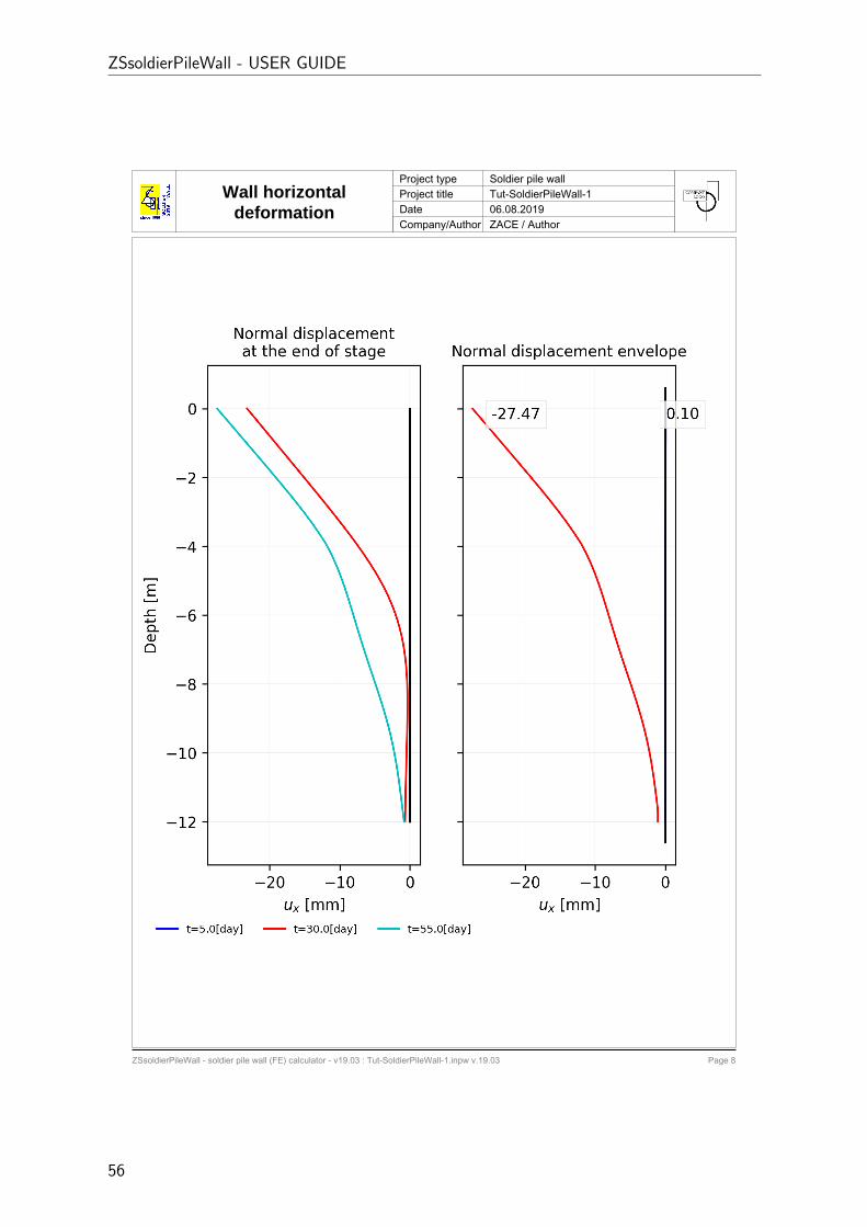
Wall horizontaldeformation
Project type Soldier pile wallProject title Tut-SoldierPileWall-1Date 06.08.2019Company/Author ZACE / Author
ZSsoldierPileWall - USER GUIDE
56
ZSsoldierPileWall - soldier pile wall (FE) calculator - v19.03 : Tut-SoldierPileWall-1.inpw v.19.03 Page 9
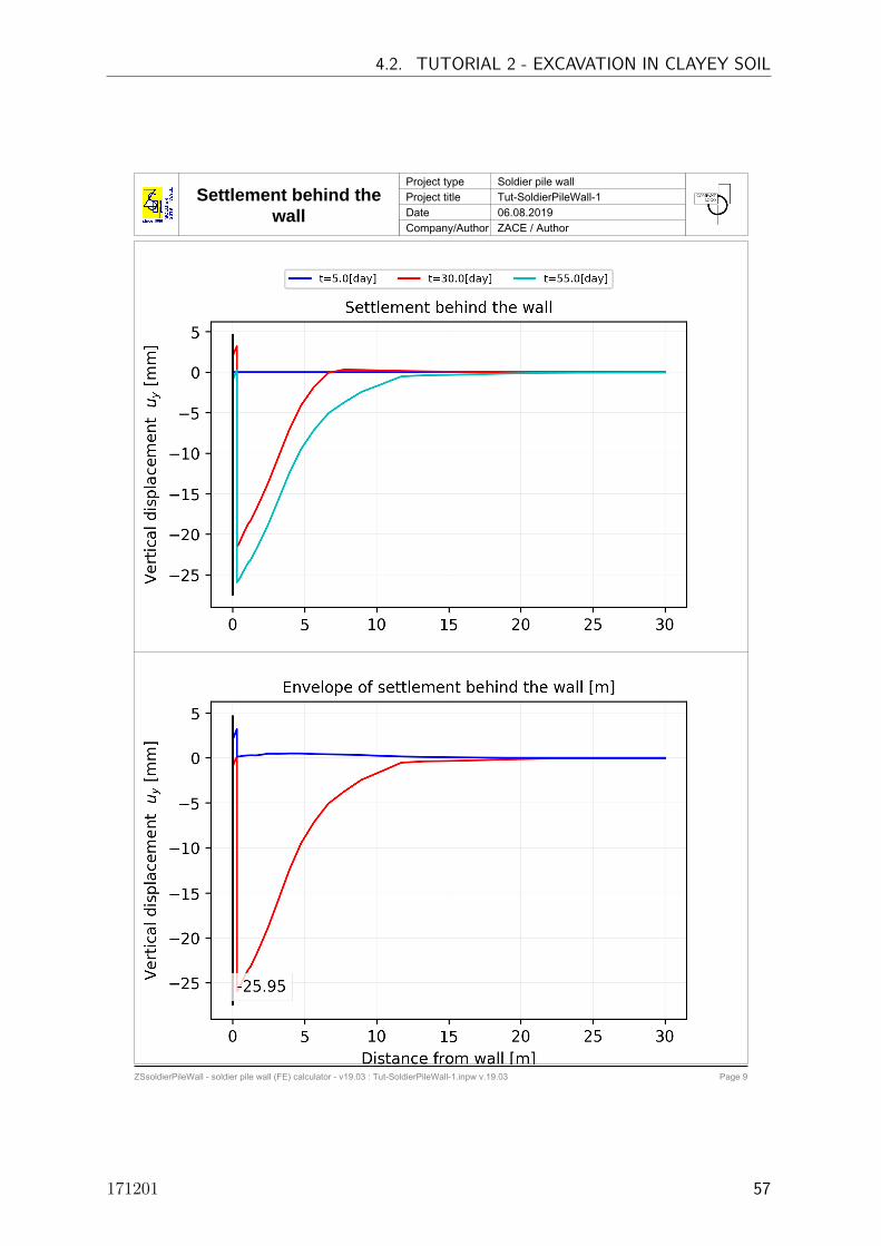
Settlement behind thewall
Project type Soldier pile wallProject title Tut-SoldierPileWall-1Date 06.08.2019Company/Author ZACE / Author
4.2. TUTORIAL 2 - EXCAVATION IN CLAYEY SOIL
171201 57

ZSsoldierPileWall - soldier pile wall (FE) calculator - v19.03 : Tut-SoldierPileWall-1.inpw v.19.03 Page 10
Sectional forcesProject type Soldier pile wallProject title Tut-SoldierPileWall-1Date 06.08.2019Company/Author ZACE / Author
ZSsoldierPileWall - USER GUIDE
58
ZSsoldierPileWall - soldier pile wall (FE) calculator - v19.03 : Tut-SoldierPileWall-1.inpw v.19.03 Page 11
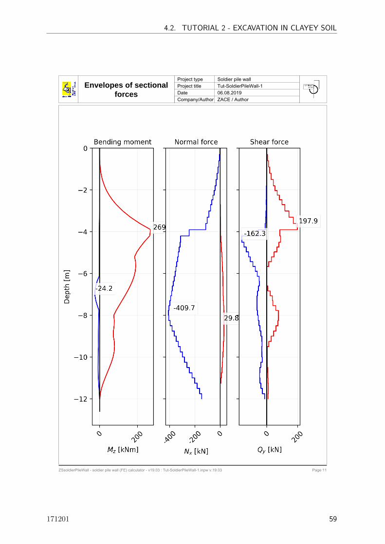
Envelopes of sectionalforces
Project type Soldier pile wallProject title Tut-SoldierPileWall-1Date 06.08.2019Company/Author ZACE / Author
4.2. TUTORIAL 2 - EXCAVATION IN CLAYEY SOIL
171201 59

Envelopes of sectionalforces
Project type Soldier pile wallProject title Tut-SoldierPileWall-1Date 06.08.2019Company/Author ZACE / Author
ZSsoldierPileWall - soldier pile wall (FE) calculator - v19.03 : Tut-SoldierPileWall-1.inpw v.19.03 Page 12
Depth [m] Mz+ [kNm] Mz- [kNm] Qy+ [kN] Qy- [kN] Nx+ [kN] Nx- [kN]
-0.00 0.00 -0.23 1.24 0.00 0.00 -1.79-0.30 0.02 -0.25 1.24 0.00 0.00 -1.79-0.30 0.02 -0.25 4.66 0.00 0.00 -5.97-0.60 0.97 -0.19 4.66 0.00 0.00 -5.97-0.60 0.97 -0.19 10.77 0.00 0.00 -10.89-0.90 3.15 0.00 10.77 0.00 0.00 -10.89-0.90 3.15 0.00 18.15 0.00 0.00 -17.25-1.20 7.42 0.00 18.15 0.00 0.00 -17.25-1.20 7.42 0.00 28.66 0.00 0.00 -25.01-1.50 14.64 0.00 28.66 0.00 0.00 -25.01-1.50 14.64 0.00 42.06 -1.13 0.00 -33.14-1.80 25.85 0.00 42.06 -1.13 0.00 -33.14-1.80 25.85 0.00 53.36 -2.10 0.00 -40.87-2.02 36.62 0.00 53.36 -2.10 0.00 -40.87-2.03 36.62 0.00 67.44 -2.61 0.00 -48.65-2.25 50.55 0.00 67.44 -2.61 0.00 -48.65-2.25 50.55 0.00 81.70 -2.88 0.00 -56.91-2.48 67.59 0.00 81.70 -2.88 0.00 -56.91-2.47 67.59 0.00 98.79 -2.95 0.04 -65.59-2.70 88.29 0.00 98.79 -2.95 0.04 -65.59-2.70 88.29 0.00 117.59 -2.83 0.93 -75.84-3.00 121.64 0.00 117.59 -2.83 0.93 -75.84-3.00 121.64 0.00 143.68 -5.39 1.86 -88.82-3.30 162.39 -0.31 143.68 -5.39 1.86 -88.82-3.30 162.39 -0.31 172.31 -7.94 2.71 -102.76-3.60 211.63 -0.84 172.31 -7.94 2.71 -102.76-3.60 211.63 -0.84 197.92 -9.25 3.46 -115.06-3.90 269.47 -1.23 197.92 -9.25 3.46 -115.06-3.90 269.47 -1.23 84.95 -54.59 4.10 -246.04-4.20 265.11 -1.50 84.95 -54.59 4.10 -246.04-4.20 265.11 -1.50 89.51 -162.27 5.58 -313.02-4.50 235.25 -1.66 89.51 -162.27 5.58 -313.02-4.50 235.25 -1.66 79.25 -147.83 8.40 -316.76-4.73 215.51 -1.71 79.25 -147.83 8.40 -316.76-4.73 215.51 -1.71 65.10 -133.08 10.75 -324.30-4.97 197.48 -1.72 65.10 -133.08 10.75 -324.30-4.97 197.48 -1.72 47.84 -118.20 12.96 -330.57-5.20 185.14 -1.69 47.84 -118.20 12.96 -330.57-5.20 185.14 -1.69 29.65 -106.42 15.00 -336.75-5.43 190.20 -1.64 29.65 -106.42 15.00 -336.75-5.43 190.20 -1.64 11.98 -90.55 16.86 -343.48-5.67 191.30 -1.57 11.98 -90.55 16.86 -343.48-5.67 191.30 -1.57 0.20 -74.56 18.50 -349.96-5.90 188.65 -1.49 0.20 -74.56 18.50 -349.96-5.90 188.65 -1.49 0.27 -61.49 19.92 -356.66-6.13 182.59 -1.92 0.27 -61.49 19.92 -356.66-6.13 182.59 -1.92 0.32 -49.04 21.10 -363.66-6.37 173.53 -12.38 0.32 -49.04 21.10 -363.66-6.37 173.53 -12.38 0.36 -48.04 22.04 -370.46-6.60 162.03 -19.92 0.36 -48.04 22.04 -370.46-6.60 162.03 -19.92 5.60 -53.64 22.74 -377.61-6.83 148.71 -24.19 5.60 -53.64 22.74 -377.61-6.83 148.71 -24.19 22.63 -59.59 23.17 -384.75-7.07 134.12 -24.12 22.63 -59.59 23.17 -384.75-7.07 134.12 -24.12 36.51 -62.97 24.60 -391.48-7.30 118.82 -19.73 36.51 -62.97 24.60 -391.48-7.30 118.82 -19.73 39.23 -63.88 26.51 -398.28-7.53 103.36 -12.17 39.23 -63.88 26.51 -398.28-7.53 103.36 -12.17 58.53 -62.61 28.02 -404.53
ZSsoldierPileWall - USER GUIDE
60

Envelopes of sectionalforces
Project type Soldier pile wallProject title Tut-SoldierPileWall-1Date 06.08.2019Company/Author ZACE / Author
ZSsoldierPileWall - soldier pile wall (FE) calculator - v19.03 : Tut-SoldierPileWall-1.inpw v.19.03 Page 13
Depth [m] Mz+ [kNm] Mz- [kNm] Qy+ [kN] Qy- [kN] Nx+ [kN] Nx- [kN]-7.77 88.24 -3.08 58.53 -62.61 28.02 -404.53-7.77 88.24 -3.08 74.32 -59.63 29.07 -409.70-8.00 75.17 -3.84 74.32 -59.63 29.07 -409.70-8.00 75.17 -3.84 75.71 -55.25 29.59 -406.79-8.25 77.70 -4.77 75.71 -55.25 29.59 -406.79-8.25 77.70 -4.77 72.89 -50.07 29.76 -395.98-8.50 77.00 -5.39 72.89 -50.07 29.76 -395.98-8.50 77.00 -5.39 60.37 -44.23 29.52 -380.40-8.75 73.49 -5.75 60.37 -44.23 29.52 -380.40-8.75 73.49 -5.75 44.72 -37.97 28.83 -364.11-9.00 72.66 -5.88 44.72 -37.97 28.83 -364.11-9.00 72.66 -5.88 28.99 -31.54 27.68 -347.85-9.25 77.84 -5.83 28.99 -31.54 27.68 -347.85-9.25 77.84 -5.83 13.71 -30.89 26.07 -331.48-9.50 79.31 -5.66 13.71 -30.89 26.07 -331.48-9.50 79.31 -5.66 2.84 -32.14 23.97 -315.06-9.75 77.14 -6.80 2.84 -32.14 23.97 -315.06-9.75 77.14 -6.80 3.31 -31.41 21.39 -298.66
-10.00 71.48 -7.35 3.31 -31.41 21.39 -298.66-10.00 71.48 -7.35 3.73 -29.35 19.14 -281.96-10.25 62.84 -7.37 3.73 -29.35 19.14 -281.96-10.25 62.84 -7.37 4.10 -39.38 16.79 -264.01-10.50 52.27 -7.71 4.10 -39.38 16.79 -264.01-10.50 52.27 -7.71 5.68 -44.68 13.71 -244.25-10.75 40.89 -7.39 5.68 -44.68 13.71 -244.25-10.75 40.89 -7.39 6.97 -45.95 9.86 -223.31-11.00 29.59 -6.36 6.97 -45.95 9.86 -223.31-11.00 29.59 -6.36 8.44 -43.67 5.19 -202.32-11.25 19.17 -4.82 8.44 -43.67 5.19 -202.32-11.25 19.17 -4.82 9.98 -37.87 0.00 -182.13-11.50 10.38 -2.96 9.98 -37.87 0.00 -182.13-11.50 10.38 -2.96 10.42 -28.14 0.00 -162.74-11.75 4.15 -1.06 10.42 -28.14 0.00 -162.74-11.75 4.15 -1.06 8.36 -13.63 0.00 -146.08-12.00 1.92 0.00 8.36 -13.63 0.00 -146.08
4.2. TUTORIAL 2 - EXCAVATION IN CLAYEY SOIL
171201 61

Envelopes - Bendingmoment
Project type Soldier pile wallProject title Tut-SoldierPileWall-1Date 06.08.2019Company/Author ZACE / Author
ZSsoldierPileWall - soldier pile wall (FE) calculator - v19.03 : Tut-SoldierPileWall-1.inpw v.19.03 Page 14
Bending moment with corresponding Shear force and Axial forceDepth [m] Mz+ [kNm] Qy [kN] Nx [kN] Mz- [kNm] Qy [kN] Nx [kN]
-0.00 0.00 0.00 0.00 -0.23 0.97 -1.79-0.30 0.02 1.24 -1.68 -0.25 0.97 -1.79-0.30 0.02 3.71 -4.75 -0.25 4.60 -5.97-0.60 0.97 3.71 -4.75 -0.19 1.15 -4.46-0.60 0.97 6.56 -6.70 -0.19 3.59 -7.69-0.90 3.15 6.56 -6.70 0.00 0.00 0.00-0.90 3.15 2.55 -4.78 0.00 0.00 0.00-1.20 7.42 18.12 -14.55 0.00 0.00 0.00-1.20 7.42 28.66 -20.80 0.00 0.00 0.00-1.50 14.64 28.66 -20.80 0.00 0.00 0.00-1.50 14.64 42.06 -27.08 0.00 0.00 0.00-1.80 25.85 42.06 -27.08 0.00 0.00 0.00-1.80 25.85 53.36 -32.87 0.00 0.00 0.00-2.02 36.62 53.36 -27.67 0.00 0.00 0.00-2.03 36.62 67.44 -32.45 0.00 0.00 0.00-2.25 50.55 67.44 -32.45 0.00 0.00 0.00-2.25 50.55 81.70 -37.38 0.00 0.00 0.00-2.48 67.59 81.70 -37.38 0.00 0.00 0.00-2.47 67.59 98.79 -42.38 0.00 0.00 0.00-2.70 88.29 98.79 -42.38 0.00 0.00 0.00-2.70 88.29 117.59 -47.91 0.00 0.00 0.00-3.00 121.64 117.59 -47.91 0.00 0.00 0.00-3.00 121.64 143.68 -54.95 0.00 0.00 0.00-3.30 162.39 143.68 -54.95 -0.31 -2.53 1.86-3.30 162.39 172.31 -62.51 -0.31 -2.13 2.71-3.60 211.63 172.31 -62.51 -0.84 -2.13 2.71-3.60 211.63 197.92 -67.68 -0.84 -1.69 3.46-3.90 269.47 197.92 -67.68 -1.23 -1.69 3.46-3.90 269.47 -16.29 -180.55 -1.23 -1.26 4.10-4.20 265.11 -16.29 -180.55 -1.50 -1.26 4.10-4.20 265.11 -110.15 -232.30 -1.50 -0.87 4.62-4.50 235.25 -110.15 -232.30 -1.66 -0.87 4.62-4.50 235.25 -98.32 -217.48 -1.66 -0.57 4.97-4.73 215.51 -91.49 -226.49 -1.71 -0.57 4.97-4.73 215.51 -79.54 -223.04 -1.71 -0.34 5.19-4.97 197.48 -79.54 -223.04 -1.72 -0.34 5.19-4.97 197.48 -70.45 -217.45 -1.72 -0.16 5.33-5.20 185.14 47.84 -71.93 -1.69 -0.16 5.33-5.20 185.14 29.65 -65.82 -1.69 -0.01 5.39-5.43 190.20 29.65 -65.82 -1.64 -0.01 5.39-5.43 190.20 11.98 -59.83 -1.64 0.11 5.35-5.67 191.30 11.98 -59.83 -1.57 0.11 5.35-5.67 191.30 -4.71 -53.99 -1.57 0.20 5.23-5.90 188.65 -4.71 -53.99 -1.49 0.20 5.23-5.90 188.65 -20.14 -48.29 -1.49 0.27 5.01-6.13 182.59 -20.14 -48.29 -1.92 -2.96 19.92-6.13 182.59 -33.83 -42.67 -1.92 -2.09 21.10-6.37 173.53 -33.83 -42.67 -12.38 -43.78 -363.66-6.37 173.53 -45.05 -37.24 -12.38 -26.22 -370.46-6.60 162.03 -45.05 -37.24 -19.92 -26.22 -370.46-6.60 162.03 -53.64 -31.97 -19.92 -11.69 -377.61-6.83 148.71 -53.64 -31.97 -24.19 -11.69 -377.61-6.83 148.71 -59.59 -26.92 -24.19 7.02 -384.75-7.07 134.12 -59.59 -26.92 -24.12 7.02 -384.75-7.07 134.12 -62.97 -22.28 -24.12 25.64 -391.48-7.30 118.82 -62.97 -22.28 -19.73 25.64 -391.48-7.30 118.82 -63.88 -18.01 -19.73 39.23 -398.28-7.53 103.36 -63.88 -18.01 -12.17 39.23 -398.28-7.53 103.36 -62.61 -14.06 -12.17 58.53 -404.53
ZSsoldierPileWall - USER GUIDE
62

Envelopes - Bendingmoment
Project type Soldier pile wallProject title Tut-SoldierPileWall-1Date 06.08.2019Company/Author ZACE / Author
ZSsoldierPileWall - soldier pile wall (FE) calculator - v19.03 : Tut-SoldierPileWall-1.inpw v.19.03 Page 15
Depth [m] Mz+ [kNm] Qy [kN] Nx [kN] Mz- [kNm] Qy [kN] Nx [kN]-7.77 88.24 -62.61 -14.06 -3.08 0.88 22.70-7.77 88.24 -59.63 -10.34 -3.08 1.08 21.85-8.00 75.17 27.11 -323.41 -3.84 -3.95 29.07-8.00 75.17 15.52 -308.86 -3.84 -2.40 29.59-8.25 77.70 15.52 -308.86 -4.77 -2.40 29.59-8.25 77.70 2.47 -294.34 -4.77 -1.16 29.76-8.50 77.00 2.47 -294.34 -5.39 -1.16 29.76-8.50 77.00 -9.83 -279.64 -5.39 -0.06 29.52-8.75 73.49 -9.83 -279.64 -5.75 -0.06 29.52-8.75 73.49 -19.96 -264.62 -5.75 0.88 28.83-9.00 72.66 44.72 -364.11 -5.88 0.88 28.83-9.00 72.66 28.99 -347.85 -5.88 1.67 27.68-9.25 77.84 28.99 -347.85 -5.83 1.67 27.68-9.25 77.84 13.71 -331.48 -5.83 2.31 26.07-9.50 79.31 13.71 -331.48 -5.66 -5.23 22.08-9.50 79.31 -1.36 -315.06 -5.66 -2.49 21.76-9.75 77.14 -1.36 -315.06 -6.80 -2.49 21.76-9.75 77.14 -15.98 -298.66 -6.80 -0.05 20.79
-10.00 71.48 -15.98 -298.66 -7.35 -0.05 20.79-10.00 71.48 -29.35 -281.96 -7.35 2.12 19.14-10.25 62.84 -29.35 -281.96 -7.37 2.12 19.14-10.25 62.84 -39.38 -264.01 -7.37 4.04 16.79-10.50 52.27 -39.38 -264.01 -7.71 -0.29 -44.86-10.50 52.27 -44.68 -244.25 -7.71 3.09 -42.15-10.75 40.89 -44.68 -244.25 -7.39 3.09 -42.15-10.75 40.89 -45.95 -223.31 -7.39 5.95 -40.27-11.00 29.59 -45.95 -223.31 -6.36 5.95 -40.27-11.00 29.59 -43.67 -202.32 -6.36 8.11 -39.29-11.25 19.17 -43.67 -202.32 -4.82 8.11 -39.29-11.25 19.17 -37.87 -182.13 -4.82 9.42 -39.30-11.50 10.38 -37.87 -182.13 -2.96 9.42 -39.30-11.50 10.38 -28.14 -162.74 -2.96 9.56 -40.41-11.75 4.15 -28.14 -162.74 -1.06 8.32 -8.70-11.75 4.15 -13.63 -146.08 -1.06 6.87 -15.31-12.00 1.92 6.19 -82.34 0.00 0.00 0.00
4.2. TUTORIAL 2 - EXCAVATION IN CLAYEY SOIL
171201 63

Envelopes - Shear forceProject type Soldier pile wallProject title Tut-SoldierPileWall-1Date 06.08.2019Company/Author ZACE / Author
ZSsoldierPileWall - soldier pile wall (FE) calculator - v19.03 : Tut-SoldierPileWall-1.inpw v.19.03 Page 16
Shear force with corresponding Bending moment and Axial forceDepth [m] Qy+ [kN] Mz [kNm] Nx [kN] Qy- [kN] Mz [kNm] Nx [kN]
-0.00 1.24 -0.20 -1.68 0.00 0.00 0.00-0.30 1.24 0.02 -1.68 0.00 0.00 0.00-0.30 4.66 -0.12 -5.36 0.00 0.00 0.00-0.60 4.66 0.73 -5.36 0.00 0.00 0.00-0.60 10.77 0.37 -10.89 0.00 0.00 0.00-0.90 10.77 2.50 -10.89 0.00 0.00 0.00-0.90 18.15 2.50 -17.25 0.00 0.00 0.00-1.20 18.15 6.40 -17.25 0.00 0.00 0.00-1.20 28.66 7.42 -20.80 0.00 0.00 0.00-1.50 28.66 14.64 -20.80 0.00 0.00 0.00-1.50 42.06 14.64 -27.08 -1.13 3.96 -3.17-1.80 42.06 25.85 -27.08 -1.13 3.50 -3.17-1.80 53.36 25.75 -27.67 -2.10 3.50 -2.31-2.02 53.36 36.62 -27.67 -2.10 2.98 -2.31-2.03 67.44 36.62 -32.45 -2.61 2.98 -1.52-2.25 67.44 50.55 -32.45 -2.61 2.38 -1.52-2.25 81.70 50.55 -37.38 -2.88 2.38 -0.73-2.48 81.70 67.59 -37.38 -2.88 1.75 -0.73-2.47 98.79 67.59 -42.38 -2.95 1.75 0.04-2.70 98.79 88.29 -42.38 -2.95 1.13 0.04-2.70 117.59 88.29 -47.91 -2.83 1.13 0.93-3.00 117.59 121.64 -47.91 -2.83 0.35 0.93-3.00 143.68 121.64 -54.95 -5.39 20.79 -8.45-3.30 143.68 162.39 -54.95 -5.39 18.87 -8.45-3.30 172.31 162.39 -62.51 -7.94 18.87 -4.82-3.60 172.31 211.63 -62.51 -7.94 16.28 -4.82-3.60 197.92 211.63 -67.68 -9.25 16.28 -1.24-3.90 197.92 269.47 -67.68 -9.25 13.36 -1.24-3.90 84.95 100.29 -73.93 -54.59 242.91 -246.04-4.20 84.95 123.50 -73.93 -54.59 225.08 -246.04-4.20 89.51 123.50 -80.47 -162.27 225.08 -313.02-4.50 89.51 147.27 -80.47 -162.27 176.33 -313.02-4.50 79.25 147.27 -83.81 -147.83 176.33 -316.76-4.73 79.25 162.88 -83.81 -147.83 141.47 -316.76-4.73 65.10 162.88 -77.98 -133.08 141.47 -324.30-4.97 65.10 175.98 -77.98 -133.08 109.50 -324.30-4.97 47.84 175.98 -71.93 -118.20 109.50 -330.57-5.20 47.84 185.14 -71.93 -118.20 81.12 -330.57-5.20 29.65 185.14 -65.82 -106.42 81.12 -336.75-5.43 29.65 190.20 -65.82 -106.42 55.38 -336.75-5.43 11.98 190.20 -59.83 -90.55 55.38 -343.48-5.67 11.98 191.30 -59.83 -90.55 33.22 -343.48-5.67 0.20 -1.57 5.23 -74.56 33.22 -349.96-5.90 0.20 -1.49 5.23 -74.56 14.73 -349.96-5.90 0.27 -1.49 5.01 -61.49 14.73 -356.66-6.13 0.27 -1.40 5.01 -61.49 -0.85 -356.66-6.13 0.32 -1.40 4.69 -49.04 129.20 -175.13-6.37 0.32 -1.31 4.69 -49.04 117.85 -175.13-6.37 0.36 -1.31 4.27 -48.04 117.85 -165.20-6.60 0.36 -1.22 4.27 -48.04 106.74 -165.20-6.60 5.60 42.69 -338.82 -53.64 162.03 -31.97-6.83 5.60 42.84 -338.82 -53.64 148.71 -31.97-6.83 22.63 42.84 -344.23 -59.59 148.71 -26.92-7.07 22.63 47.09 -344.23 -59.59 134.12 -26.92-7.07 36.51 47.09 -348.55 -62.97 134.12 -22.28-7.30 36.51 54.95 -348.55 -62.97 118.82 -22.28-7.30 39.23 -19.73 -398.28 -63.88 118.82 -18.01-7.53 39.23 -12.17 -398.28 -63.88 103.36 -18.01-7.53 58.53 -12.17 -404.53 -62.61 103.36 -14.06
ZSsoldierPileWall - USER GUIDE
64

Envelopes - Shear forceProject type Soldier pile wallProject title Tut-SoldierPileWall-1Date 06.08.2019Company/Author ZACE / Author
ZSsoldierPileWall - soldier pile wall (FE) calculator - v19.03 : Tut-SoldierPileWall-1.inpw v.19.03 Page 17
Depth [m] Qy+ [kN] Mz [kNm] Nx [kN] Qy- [kN] Mz [kNm] Nx [kN]-7.77 58.53 0.05 -404.53 -62.61 88.24 -14.06-7.77 74.32 0.05 -409.70 -59.63 88.24 -10.34-8.00 74.32 16.31 -409.70 -59.63 73.84 -10.34-8.00 75.71 16.31 -406.79 -55.25 73.84 -6.76-8.25 75.71 34.12 -406.79 -55.25 59.54 -6.76-8.25 72.89 34.12 -395.98 -50.07 59.54 -3.44-8.50 72.89 50.63 -395.98 -50.07 46.52 -3.44-8.50 60.37 50.63 -380.40 -44.23 46.52 -0.43-8.75 60.37 63.62 -380.40 -44.23 34.95 -0.43-8.75 44.72 63.62 -364.11 -37.97 34.95 2.25-9.00 44.72 72.66 -364.11 -37.97 24.93 2.25-9.00 28.99 72.66 -347.85 -31.54 24.93 4.56-9.25 28.99 77.84 -347.85 -31.54 16.50 4.56-9.25 13.71 77.84 -331.48 -30.89 60.50 -234.40-9.50 13.71 79.31 -331.48 -30.89 52.34 -234.40-9.50 2.84 -5.62 23.97 -32.14 52.34 -220.01-9.75 2.84 -5.30 23.97 -32.14 43.91 -220.01-9.75 3.31 -5.30 21.39 -31.41 43.91 -206.12
-10.00 3.31 -4.87 21.39 -31.41 35.67 -206.12-10.00 3.73 -4.87 18.33 -29.35 71.48 -281.96-10.25 3.73 -4.35 18.33 -29.35 62.84 -281.96-10.25 4.10 -4.35 14.80 -39.38 62.84 -264.01-10.50 4.10 -3.74 14.80 -39.38 52.27 -264.01-10.50 5.68 -6.91 13.71 -44.68 52.27 -244.25-10.75 5.68 -6.06 13.71 -44.68 40.89 -244.25-10.75 6.97 -6.06 9.86 -45.95 40.89 -223.31-11.00 6.97 -4.89 9.86 -45.95 29.59 -223.31-11.00 8.44 -5.99 -52.32 -43.67 29.59 -202.32-11.25 8.44 -4.52 -52.32 -43.67 19.17 -202.32-11.25 9.98 -4.52 -50.61 -37.87 19.17 -182.13-11.50 9.98 -2.66 -50.61 -37.87 10.38 -182.13-11.50 10.42 -2.66 -50.02 -28.14 10.38 -162.74-11.75 10.42 -0.67 -50.02 -28.14 4.15 -162.74-11.75 8.36 -0.67 -50.75 -13.63 4.15 -146.08-12.00 8.36 1.12 -50.75 -13.63 1.17 -146.08
4.2. TUTORIAL 2 - EXCAVATION IN CLAYEY SOIL
171201 65

Envelopes - Axial forceProject type Soldier pile wallProject title Tut-SoldierPileWall-1Date 06.08.2019Company/Author ZACE / Author
ZSsoldierPileWall - soldier pile wall (FE) calculator - v19.03 : Tut-SoldierPileWall-1.inpw v.19.03 Page 18
Axial force with corresponding Shear force and Bending momentDepth [m] Nx+ [kN] Qy [kN] Mz [kNm] Nx- [kN] Qy [kN] Mz [kNm]
-0.00 0.00 0.00 0.00 -1.79 0.97 0.00-0.30 0.00 0.00 0.00 -1.79 0.97 0.00-0.30 0.00 0.00 0.00 -5.97 4.60 0.00-0.60 0.00 0.00 0.00 -5.97 4.60 0.00-0.60 0.00 0.00 0.00 -10.89 10.77 0.00-0.90 0.00 0.00 0.00 -10.89 10.77 0.00-0.90 0.00 0.00 0.00 -17.25 18.15 0.00-1.20 0.00 0.00 0.00 -17.25 18.15 0.00-1.20 0.00 0.00 0.00 -25.01 28.57 0.00-1.50 0.00 0.00 0.00 -25.01 28.57 0.00-1.50 0.00 0.00 0.00 -33.14 41.75 0.00-1.80 0.00 0.00 0.00 -33.14 41.75 0.00-1.80 0.00 0.00 0.00 -40.87 52.78 0.00-2.02 0.00 0.00 0.00 -40.87 52.78 0.00-2.03 0.00 0.00 0.00 -48.65 66.05 0.00-2.25 0.00 0.00 0.00 -48.65 66.05 0.00-2.25 0.00 0.00 0.00 -56.91 79.11 0.00-2.48 0.00 0.00 0.00 -56.91 79.11 0.00-2.47 0.04 -2.95 1.75 -65.59 95.02 1.75-2.70 0.04 -2.95 1.13 -65.59 95.02 1.13-2.70 0.93 -2.83 1.13 -75.84 111.85 1.13-3.00 0.93 -2.83 0.35 -75.84 111.85 0.35-3.00 1.86 -2.53 0.35 -88.82 135.51 0.35-3.30 1.86 -2.53 -0.31 -88.82 135.51 -0.31-3.30 2.71 -2.13 -0.31 -102.76 160.36 -0.31-3.60 2.71 -2.13 -0.84 -102.76 160.36 -0.84-3.60 3.46 -1.69 -0.84 -115.06 183.43 -0.84-3.90 3.46 -1.69 -1.23 -115.06 183.43 -1.23-3.90 4.10 -1.26 -1.23 -246.04 -54.59 -1.23-4.20 4.10 -1.26 -1.50 -246.04 -54.59 -1.50-4.20 5.58 -9.29 10.39 -313.02 -162.27 10.39-4.50 5.58 -9.29 7.56 -313.02 -162.27 7.56-4.50 8.40 -8.60 7.56 -316.76 -147.83 7.56-4.73 8.40 -8.60 5.54 -316.76 -147.83 5.54-4.73 10.75 -7.79 5.54 -324.30 -133.08 5.54-4.97 10.75 -7.79 3.72 -324.30 -133.08 3.72-4.97 12.96 -6.86 3.72 -330.57 -118.20 3.72-5.20 12.96 -6.86 2.14 -330.57 -118.20 2.14-5.20 15.00 -5.88 2.14 -336.75 -106.42 2.14-5.43 15.00 -5.88 0.78 -336.75 -106.42 0.78-5.43 16.86 -4.88 0.78 -343.48 -90.55 0.78-5.67 16.86 -4.88 -0.33 -343.48 -90.55 -0.33-5.67 18.50 -3.89 -0.33 -349.96 -74.56 -0.33-5.90 18.50 -3.89 -1.23 -349.96 -74.56 -1.23-5.90 19.92 -2.96 -1.23 -356.66 -61.49 -1.23-6.13 19.92 -2.96 -1.92 -356.66 -61.49 -1.92-6.13 21.10 -2.09 -1.92 -363.66 -43.78 -1.92-6.37 21.10 -2.09 -2.42 -363.66 -43.78 -2.42-6.37 22.04 -1.32 -2.42 -370.46 -26.22 -2.42-6.60 22.04 -1.32 -2.75 -370.46 -26.22 -2.75-6.60 22.74 -0.66 -2.75 -377.61 -11.69 -2.75-6.83 22.74 -0.66 -2.95 -377.61 -11.69 -2.95-6.83 23.17 -0.12 -2.95 -384.75 7.02 -2.95-7.07 23.17 -0.12 -3.06 -384.75 7.02 -3.06-7.07 24.60 -9.41 3.17 -391.48 25.64 3.17-7.30 24.60 -9.41 0.82 -391.48 25.64 0.82-7.30 26.51 -7.43 0.82 -398.28 39.23 0.82-7.53 26.51 -7.43 -1.10 -398.28 39.23 -1.10-7.53 28.02 -5.61 -1.10 -404.53 58.53 -1.10
ZSsoldierPileWall - USER GUIDE
66

Envelopes - Axial forceProject type Soldier pile wallProject title Tut-SoldierPileWall-1Date 06.08.2019Company/Author ZACE / Author
ZSsoldierPileWall - soldier pile wall (FE) calculator - v19.03 : Tut-SoldierPileWall-1.inpw v.19.03 Page 19
Depth [m] Nx+ [kN] Qy [kN] Mz [kNm] Nx- [kN] Qy [kN] Mz [kNm]-7.77 28.02 -5.61 -2.63 -404.53 58.53 -2.63-7.77 29.07 -3.95 -2.63 -409.70 74.32 -2.63-8.00 29.07 -3.95 -3.84 -409.70 74.32 -3.84-8.00 29.59 -2.40 -3.84 -406.79 75.71 -3.84-8.25 29.59 -2.40 -4.77 -406.79 75.71 -4.77-8.25 29.76 -1.16 -4.77 -395.98 72.89 -4.77-8.50 29.76 -1.16 -5.39 -395.98 72.89 -5.39-8.50 29.52 -0.06 -5.39 -380.40 60.37 -5.39-8.75 29.52 -0.06 -5.75 -380.40 60.37 -5.75-8.75 28.83 0.88 -5.75 -364.11 44.72 -5.75-9.00 28.83 0.88 -5.88 -364.11 44.72 -5.88-9.00 27.68 1.67 -5.88 -347.85 28.99 -5.88-9.25 27.68 1.67 -5.83 -347.85 28.99 -5.83-9.25 26.07 2.31 -5.83 -331.48 13.71 -5.83-9.50 26.07 2.31 -5.62 -331.48 13.71 -5.62-9.50 23.97 2.84 -5.62 -315.06 -1.36 -5.62-9.75 23.97 2.84 -5.30 -315.06 -1.36 -5.30-9.75 21.39 3.31 -5.30 -298.66 -15.98 -5.30
-10.00 21.39 3.31 -4.87 -298.66 -15.98 -4.87-10.00 19.14 2.12 -7.35 -281.96 -29.35 -7.35-10.25 19.14 2.12 -7.37 -281.96 -29.35 -7.37-10.25 16.79 4.04 -7.37 -264.01 -39.38 -7.37-10.50 16.79 4.04 -6.91 -264.01 -39.38 -6.91-10.50 13.71 5.68 -6.91 -244.25 -44.68 -6.91-10.75 13.71 5.68 -6.06 -244.25 -44.68 -6.06-10.75 9.86 6.97 -6.06 -223.31 -45.95 -6.06-11.00 9.86 6.97 -4.89 -223.31 -45.95 -4.89-11.00 5.19 7.73 -4.89 -202.32 -43.67 -4.89-11.25 5.19 7.73 -3.54 -202.32 -43.67 -3.54-11.25 0.00 0.00 0.00 -182.13 -37.87 0.00-11.50 0.00 0.00 0.00 -182.13 -37.87 0.00-11.50 0.00 0.00 0.00 -162.74 -28.14 0.00-11.75 0.00 0.00 0.00 -162.74 -28.14 0.00-11.75 0.00 0.00 0.00 -146.08 -13.63 0.00-12.00 0.00 0.00 0.00 -146.08 -13.63 0.00
4.2. TUTORIAL 2 - EXCAVATION IN CLAYEY SOIL
171201 67
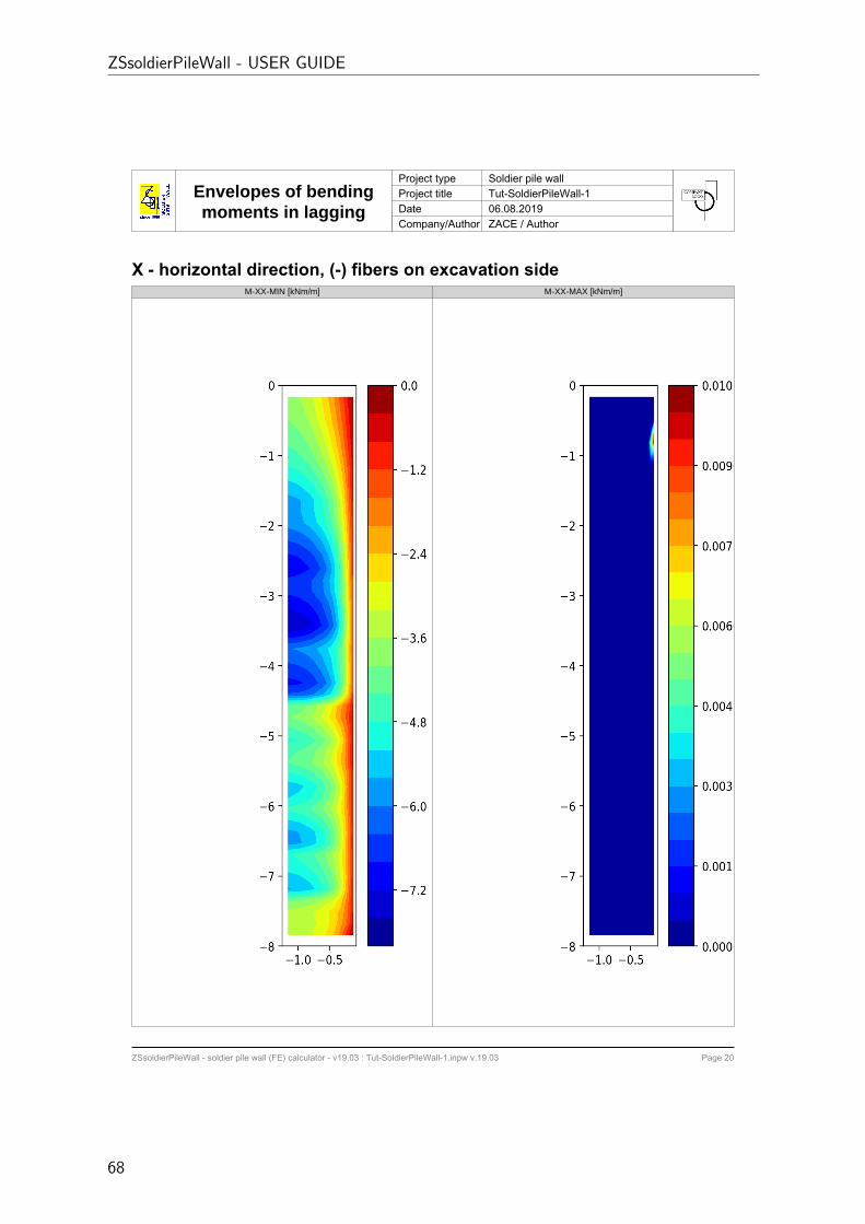
Envelopes of bendingmoments in lagging
Project type Soldier pile wallProject title Tut-SoldierPileWall-1Date 06.08.2019Company/Author ZACE / Author
ZSsoldierPileWall - soldier pile wall (FE) calculator - v19.03 : Tut-SoldierPileWall-1.inpw v.19.03 Page 20
X - horizontal direction, (-) fibers on excavation sideM-XX-MIN [kNm/m] M-XX-MAX [kNm/m]
ZSsoldierPileWall - USER GUIDE
68
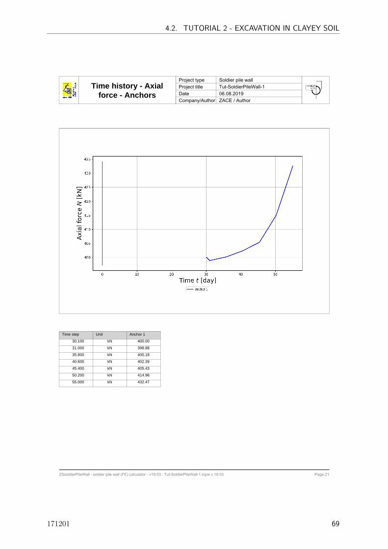
Time history - Axialforce - Anchors
Project type Soldier pile wallProject title Tut-SoldierPileWall-1Date 06.08.2019Company/Author ZACE / Author
ZSsoldierPileWall - soldier pile wall (FE) calculator - v19.03 : Tut-SoldierPileWall-1.inpw v.19.03 Page 21
Time step Unit Anchor 1
30.100 kN 400.00
31.000 kN 398.88
35.800 kN 400.18
40.600 kN 402.39
45.400 kN 405.43
50.200 kN 414.96
55.000 kN 432.47
4.2. TUTORIAL 2 - EXCAVATION IN CLAYEY SOIL
171201 69

ZSsoldierPileWall - USER GUIDE
Appendix A.2: Automatic report for Tutorial 2
70

Geometry and FE modelProject type Soldier pile wallProject title Tut-SoldierPileWall-2Date 06.08.2019Company/Author ZACE / Author
ZSsoldierPileWall - soldier pile wall (FE) calculator - v19.03 : Tut-SoldierPileWall-2.inpw v.19.03 Page 1
0.00m
2.00
20.00m
2.00
L=9.0m
Lf=8.0m, α=25⁰Lv=6.0m
Anchor 1: F₀=300kN
3.00
10kN/m²
H=2
0.0m
B₁=15.0m B₂=30.0m
6.0m
4.2. TUTORIAL 2 - EXCAVATION IN CLAYEY SOIL
171201 71

Wall and supportingsystem characteristics
Project type Soldier pile wallProject title Tut-SoldierPileWall-2Date 06.08.2019Company/Author ZACE / Author
ZSsoldierPileWall - soldier pile wall (FE) calculator - v19.03 : Tut-SoldierPileWall-2.inpw v.19.03 Page 2
Wall characteristicsProperty Symbol Unit Value
Detailed construction type Pile strengthened by a profile
Length L m 9.0
Spacing (out of plane) s m 2.2
Installation time t0
day 5.0
Profile(s)
Selected profile - EU-HEB-240
Profile flange width b mm 200.0
Young's modulus E MPa 200000.0
Poisson's coefficient ν - 0.2
Cross section area A cm2 105.986
Momentum of inertia I cm4 11259.3
Unit weight γ kN/m3 78.5
Soil-beam interface friction coeff. ratio Rint
- 0.6
Pile
Class of concrete - C20/25
Young's modulus E MPa 30000.0
Poisson's coefficient ν - 0.2
Diameter d cm 60.0
Unit weight γ kN/m3 24.0
Soil-pile interface friction coeff. ratio Rint
- 1.0
Lagging
Material type - Wood
Class of material - C22
Thickness t cm 10.0
Young's modulus E MPa 10000.0
Poisson's coefficient ν - 0.2
Unit weight γ kN/m3 4.1
Technological gap in soil-lagging interface gi
cm 0.0
Soil-lagging interface friction ratio Rint
- 0.6
ZSsoldierPileWall - USER GUIDE
72

Wall and supportingsystem characteristics
Project type Soldier pile wallProject title Tut-SoldierPileWall-2Date 06.08.2019Company/Author ZACE / Author
ZSsoldierPileWall - soldier pile wall (FE) calculator - v19.03 : Tut-SoldierPileWall-2.inpw v.19.03 Page 3
AnchorsProperty Symbol Unit ANCHOR 1
Free anchor length Lf
m 8.0
Anchor bond length Lv
m 6.0
Depth z m 3.0
Young's modulus E MPa 210000.0
Cross section area A cm2 4.5
Prestress force F0
kN 300.0
Inclination angle α deg 25.0
Anchor spacing (out of plane) s m 1.0
Diameter of drill hole Ddh
mm 150.0
External shear resistance qs
kPa 300.0
Installation time t-t0
day 15.0
4.2. TUTORIAL 2 - EXCAVATION IN CLAYEY SOIL
171201 73

General settingsProject type Soldier pile wallProject title Tut-SoldierPileWall-2Date 06.08.2019Company/Author ZACE / Author
ZSsoldierPileWall - soldier pile wall (FE) calculator - v19.03 : Tut-SoldierPileWall-2.inpw v.19.03 Page 4
Analysis settingsProperty Unit Value
Type of analysis Two-phase Consolidation
Duration of excavation stages after wall installation [day] 29.0
Duration of consolidation after completing the excavation [day] 120.0
Number of computational steps for each excavation stage [-] 2
FE mesh density Automatic
ZSsoldierPileWall - USER GUIDE
74

Construction stagesProject type Soldier pile wallProject title Tut-SoldierPileWall-2Date 06.08.2019Company/Author ZACE / Author
ZSsoldierPileWall - soldier pile wall (FE) calculator - v19.03 : Tut-SoldierPileWall-2.inpw v.19.03 Page 5
IN SITU - WALL WALL - ANCH:1ANCH:1 -EXC.END
Analysis status Completed Completed Completed
Offset between anchor/nail and platform 0.5 [m]
Delay of excavation beginning 0.0 [day] 1.0 [day]
Excavation stage split 5 4
Number of computational steps for this stage 2 2
Time step amplification factor 1.0 1.0
Break after last excavation step in this stage 14.0 [day]
EXC.END - END
Analysis status Completed
Offset between anchor/nail and platform
Delay of excavation beginning
Excavation stage split
Number of computational steps for this stage 20
Time step amplification factor 1.1
Break after last excavation step in this stage
4.2. TUTORIAL 2 - EXCAVATION IN CLAYEY SOIL
171201 75

ZSsoldierPileWall - soldier pile wall (FE) calculator - v19.03 : Tut-SoldierPileWall-2.inpw v.19.03 Page 6
Soil ParametersProject type Soldier pile wallProject title Tut-SoldierPileWall-2Date 06.08.2019Company/Author ZACE / Author
Parameter Symbol Unit Sand 1 Clay 1
Unit weight
Unit weight γ [kN/m3] 19.0 20.4
Dry unit weight γD
[kN/m3] 16.52 16.7
Voids ratio e0
[-] 0.604 0.587
Deformation
Un-/reloading modulus Eur
ref [kPa] 80000.0 55000.0
Poisson's coefficient ν [-] 0.2 0.25
Stiffness exponent m [-] 0.5 0.9
Extension to small strain stiffness HSs [-] Inactive Inactive
Small strain initial modulus E0ref [kPa] 240000.0 300000.0
Small strain stiffness threshold γ0.7
[-] 0.0001 0.0001
Reference stress σref
[kPa] 100.0 100.0
Secant modulus E50
ref [kPa] 27000.0 12000.0
Strength
Friction angle φ [deg] 34.0 26.0
Cohesion c [kPa] 1.0 5.0
Dilatancy
Dilatancy angle ψ [deg] 4.0 0.0
Reference oedometric modulus Eoed
ref [kPa] 27000.0 12000.0
Compressibility
Ko for normally-consolidated soil K0NC [-] 0.441 0.562
Reference vertical oedometric stress σoed
ref [kPa] 200.0 200.0
Stress history Stresshistory
via OCR via qPOP
Initial state
Automatic evaluation 0 1
In situ Ko coefficient K0in situ [-] 0.5 0.586
Stress history
Overconsolidation ratio OCR [-] 1.1 1.1
Preoverburden pressure qPOP [kPa] 300.0 350.0
Permeability
Permeability coefficient in horizontal direction kh
[m/s] 0.0001 1e-09
Permeability coefficient in vertical direction kv
[m/s] 0.0001 1e-10
Soil water retention curve
Saturation constant α [1/m] 5.0 0.1
Residual degree of saturation Sr
[-] 0.0 0.0
Fluid bulk modulus KF
[kPa] 200000.0 200000.0
ZSsoldierPileWall - USER GUIDE
76

ZSsoldierPileWall - soldier pile wall (FE) calculator - v19.03 : Tut-SoldierPileWall-2.inpw v.19.03 Page 7
Wall head/tip horizontalmovement time history
Project type Soldier pile wallProject title Tut-SoldierPileWall-2Date 06.08.2019Company/Author ZACE / Author
4.2. TUTORIAL 2 - EXCAVATION IN CLAYEY SOIL
171201 77
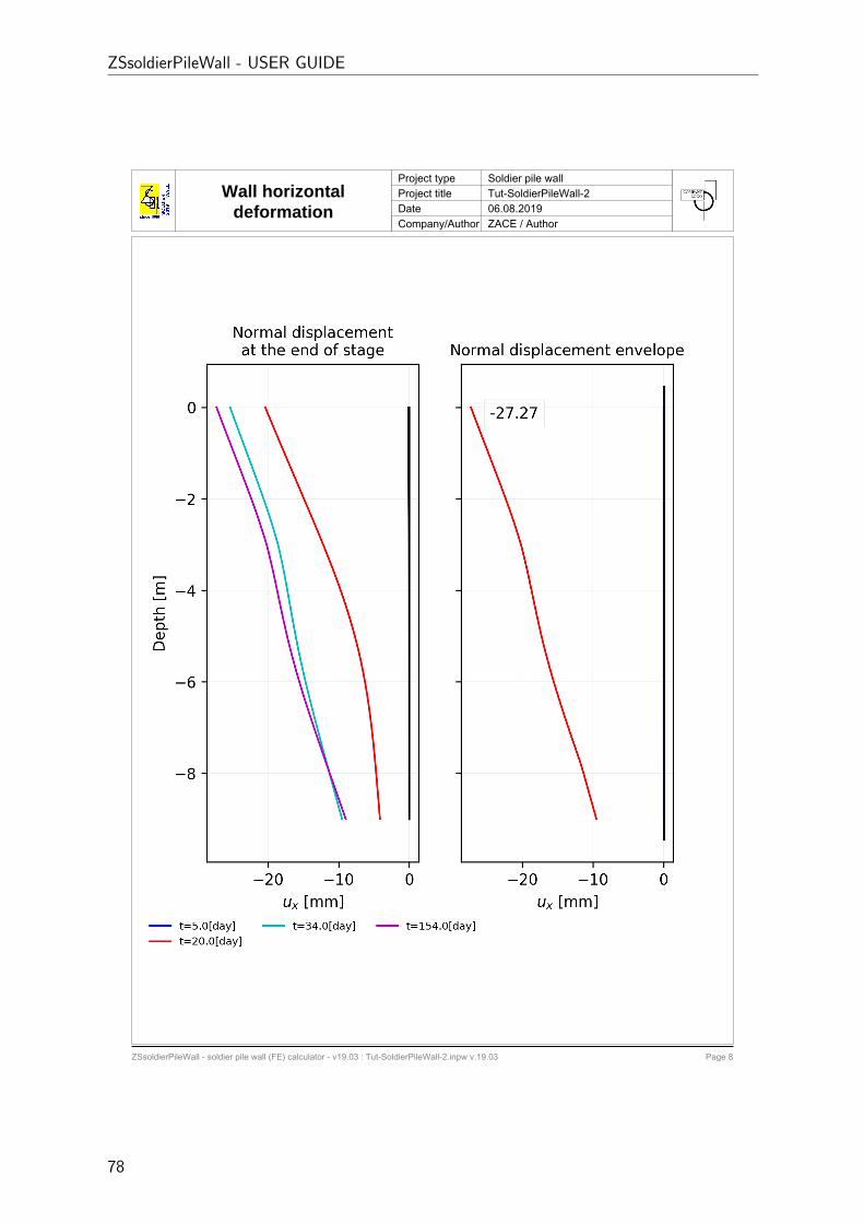
ZSsoldierPileWall - soldier pile wall (FE) calculator - v19.03 : Tut-SoldierPileWall-2.inpw v.19.03 Page 8
Wall horizontaldeformation
Project type Soldier pile wallProject title Tut-SoldierPileWall-2Date 06.08.2019Company/Author ZACE / Author
ZSsoldierPileWall - USER GUIDE
78

ZSsoldierPileWall - soldier pile wall (FE) calculator - v19.03 : Tut-SoldierPileWall-2.inpw v.19.03 Page 9
Settlement behind thewall
Project type Soldier pile wallProject title Tut-SoldierPileWall-2Date 06.08.2019Company/Author ZACE / Author
4.2. TUTORIAL 2 - EXCAVATION IN CLAYEY SOIL
171201 79

ZSsoldierPileWall - soldier pile wall (FE) calculator - v19.03 : Tut-SoldierPileWall-2.inpw v.19.03 Page 10
Sectional forcesProject type Soldier pile wallProject title Tut-SoldierPileWall-2Date 06.08.2019Company/Author ZACE / Author
ZSsoldierPileWall - USER GUIDE
80

ZSsoldierPileWall - soldier pile wall (FE) calculator - v19.03 : Tut-SoldierPileWall-2.inpw v.19.03 Page 11
Envelopes of sectionalforces
Project type Soldier pile wallProject title Tut-SoldierPileWall-2Date 06.08.2019Company/Author ZACE / Author
4.2. TUTORIAL 2 - EXCAVATION IN CLAYEY SOIL
171201 81

Envelopes of sectionalforces
Project type Soldier pile wallProject title Tut-SoldierPileWall-2Date 06.08.2019Company/Author ZACE / Author
ZSsoldierPileWall - soldier pile wall (FE) calculator - v19.03 : Tut-SoldierPileWall-2.inpw v.19.03 Page 12
Depth [m] Mz+ [kNm] Mz- [kNm] Qy+ [kN] Qy- [kN] Nx+ [kN] Nx- [kN]
-0.00 0.02 -0.45 3.81 -0.49 0.00 -2.46-0.23 0.91 -0.71 3.81 -0.49 0.00 -2.46-0.23 0.91 -0.71 10.50 0.00 0.00 -5.16-0.47 3.31 -0.98 10.50 0.00 0.00 -5.16-0.47 3.31 -0.98 18.57 0.00 0.00 -8.80-0.70 7.50 -0.93 18.57 0.00 0.00 -8.80-0.70 7.50 -0.93 26.64 0.00 0.00 -13.11-0.93 13.43 -0.72 26.64 0.00 0.00 -13.11-0.93 13.43 -0.72 36.83 -0.35 0.00 -17.94-1.17 21.62 0.00 36.83 -0.35 0.00 -17.94-1.17 21.62 0.00 48.42 -1.24 0.00 -22.98-1.40 32.45 0.00 48.42 -1.24 0.00 -22.98-1.40 32.45 0.00 59.66 -2.57 0.00 -28.21-1.63 45.81 0.00 59.66 -2.57 0.00 -28.21-1.63 45.81 0.00 73.55 -3.64 0.00 -33.81-1.87 62.29 -0.06 73.55 -3.64 0.00 -33.81-1.87 62.29 -0.06 88.24 -4.40 0.00 -39.55-2.10 82.09 -0.99 88.24 -4.40 0.00 -39.55-2.10 82.09 -0.99 101.05 -5.12 0.00 -44.84-2.33 104.63 -2.03 101.05 -5.12 0.00 -44.84-2.33 104.63 -2.03 117.09 -5.36 0.00 -50.68-2.57 130.55 -2.96 117.09 -5.36 0.00 -50.68-2.57 130.55 -2.96 134.70 -5.19 0.00 -57.08-2.80 160.66 -3.74 134.70 -5.19 0.00 -57.08-2.80 160.66 -3.74 111.73 -5.23 0.00 -82.48-3.03 186.16 -4.35 111.73 -5.23 0.00 -82.48-3.03 186.16 -4.35 55.16 -164.43 0.00 -207.80-3.27 162.91 -4.80 55.16 -164.43 0.00 -207.80-3.27 162.91 -4.80 62.08 -148.83 0.00 -209.13-3.50 146.01 -5.11 62.08 -148.83 0.00 -209.13-3.50 146.01 -5.11 60.67 -137.84 0.00 -211.01-3.71 133.21 -5.27 60.67 -137.84 0.00 -211.01-3.71 133.21 -5.27 55.97 -125.74 0.00 -217.02-3.92 120.67 -5.33 55.97 -125.74 0.00 -217.02-3.92 120.67 -5.33 48.63 -112.25 0.00 -221.52-4.12 109.71 -5.36 48.63 -112.25 0.00 -221.52-4.13 109.71 -5.36 39.87 -100.43 0.00 -225.76-4.33 104.91 -21.30 39.87 -100.43 0.00 -225.76-4.33 104.91 -21.30 31.18 -84.74 0.00 -230.11-4.54 110.18 -39.51 31.18 -84.74 0.00 -230.11-4.54 110.18 -39.51 22.82 -67.98 0.00 -234.97-4.75 113.77 -54.35 22.82 -67.98 0.00 -234.97-4.75 113.77 -54.35 14.25 -53.65 0.00 -239.87-4.96 115.62 -66.22 14.25 -53.65 0.00 -239.87-4.96 115.62 -66.22 5.36 -35.35 0.00 -244.33-5.17 115.67 -74.37 5.36 -35.35 0.00 -244.33-5.17 115.67 -74.37 7.22 -28.14 0.00 -249.45-5.38 113.92 -78.57 7.22 -28.14 0.00 -249.45-5.38 113.92 -78.57 10.35 -27.11 0.00 -254.53-5.58 110.48 -79.40 10.35 -27.11 0.00 -254.53-5.58 110.48 -79.40 21.19 -26.94 0.00 -258.97-5.79 105.47 -75.99 21.19 -26.94 0.00 -258.97-5.79 105.47 -75.99 39.21 -27.15 0.00 -263.81-6.00 99.05 -69.30 39.21 -27.15 0.00 -263.81-6.00 99.05 -69.30 43.49 -32.69 0.00 -263.90-6.25 90.20 -60.14 43.49 -32.69 0.00 -263.90-6.25 90.20 -60.14 46.15 -37.72 0.00 -257.76-6.50 80.37 -50.30 46.15 -37.72 0.00 -257.76-6.50 80.37 -50.30 45.10 -40.70 0.00 -250.34
ZSsoldierPileWall - USER GUIDE
82

Envelopes of sectionalforces
Project type Soldier pile wallProject title Tut-SoldierPileWall-2Date 06.08.2019Company/Author ZACE / Author
ZSsoldierPileWall - soldier pile wall (FE) calculator - v19.03 : Tut-SoldierPileWall-2.inpw v.19.03 Page 13
Depth [m] Mz+ [kNm] Mz- [kNm] Qy+ [kN] Qy- [kN] Nx+ [kN] Nx- [kN]-6.75 69.86 -40.81 45.10 -40.70 0.00 -250.34-6.75 69.86 -40.81 42.08 -41.73 0.00 -242.11-7.00 59.13 -32.05 42.08 -41.73 0.00 -242.11-7.00 59.13 -32.05 38.08 -41.16 0.00 -233.38-7.25 48.58 -24.18 38.08 -41.16 0.00 -233.38-7.25 48.58 -24.18 33.58 -39.31 0.00 -224.18-7.50 38.52 -17.29 33.58 -39.31 0.00 -224.18-7.50 38.52 -17.29 28.48 -36.41 0.00 -214.46-7.75 29.20 -11.54 28.48 -36.41 0.00 -214.46-7.75 29.20 -11.54 23.07 -32.61 0.00 -204.19-8.00 20.84 -7.00 23.07 -32.61 0.00 -204.19-8.00 20.84 -7.00 17.62 -27.96 0.00 -193.34-8.25 13.64 -3.65 17.62 -27.96 0.00 -193.34-8.25 13.64 -3.65 12.44 -22.43 0.00 -181.99-8.50 7.82 -1.47 12.44 -22.43 0.00 -181.99-8.50 7.82 -1.47 8.05 -15.87 0.00 -170.17-8.75 3.64 -0.24 8.05 -15.87 0.00 -170.17-8.75 3.64 -0.24 6.76 -8.12 0.00 -159.76-9.00 1.63 0.00 6.76 -8.12 0.00 -159.76
4.2. TUTORIAL 2 - EXCAVATION IN CLAYEY SOIL
171201 83
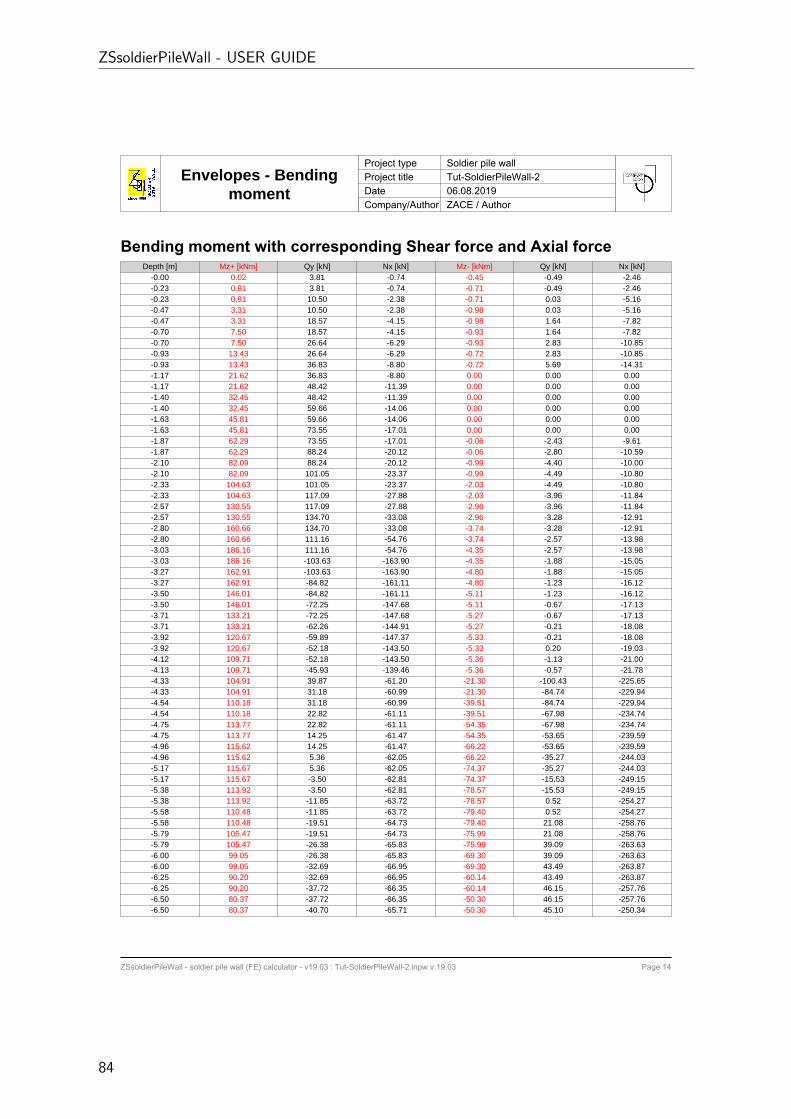
Envelopes - Bendingmoment
Project type Soldier pile wallProject title Tut-SoldierPileWall-2Date 06.08.2019Company/Author ZACE / Author
ZSsoldierPileWall - soldier pile wall (FE) calculator - v19.03 : Tut-SoldierPileWall-2.inpw v.19.03 Page 14
Bending moment with corresponding Shear force and Axial forceDepth [m] Mz+ [kNm] Qy [kN] Nx [kN] Mz- [kNm] Qy [kN] Nx [kN]
-0.00 0.02 3.81 -0.74 -0.45 -0.49 -2.46-0.23 0.91 3.81 -0.74 -0.71 -0.49 -2.46-0.23 0.91 10.50 -2.38 -0.71 0.03 -5.16-0.47 3.31 10.50 -2.38 -0.98 0.03 -5.16-0.47 3.31 18.57 -4.15 -0.98 1.64 -7.82-0.70 7.50 18.57 -4.15 -0.93 1.64 -7.82-0.70 7.50 26.64 -6.29 -0.93 2.83 -10.85-0.93 13.43 26.64 -6.29 -0.72 2.83 -10.85-0.93 13.43 36.83 -8.80 -0.72 5.69 -14.31-1.17 21.62 36.83 -8.80 0.00 0.00 0.00-1.17 21.62 48.42 -11.39 0.00 0.00 0.00-1.40 32.45 48.42 -11.39 0.00 0.00 0.00-1.40 32.45 59.66 -14.06 0.00 0.00 0.00-1.63 45.81 59.66 -14.06 0.00 0.00 0.00-1.63 45.81 73.55 -17.01 0.00 0.00 0.00-1.87 62.29 73.55 -17.01 -0.06 -2.43 -9.61-1.87 62.29 88.24 -20.12 -0.06 -2.80 -10.59-2.10 82.09 88.24 -20.12 -0.99 -4.40 -10.00-2.10 82.09 101.05 -23.37 -0.99 -4.49 -10.80-2.33 104.63 101.05 -23.37 -2.03 -4.49 -10.80-2.33 104.63 117.09 -27.88 -2.03 -3.96 -11.84-2.57 130.55 117.09 -27.88 -2.96 -3.96 -11.84-2.57 130.55 134.70 -33.08 -2.96 -3.28 -12.91-2.80 160.66 134.70 -33.08 -3.74 -3.28 -12.91-2.80 160.66 111.16 -54.76 -3.74 -2.57 -13.98-3.03 186.16 111.16 -54.76 -4.35 -2.57 -13.98-3.03 186.16 -103.63 -163.90 -4.35 -1.88 -15.05-3.27 162.91 -103.63 -163.90 -4.80 -1.88 -15.05-3.27 162.91 -84.82 -161.11 -4.80 -1.23 -16.12-3.50 146.01 -84.82 -161.11 -5.11 -1.23 -16.12-3.50 146.01 -72.25 -147.68 -5.11 -0.67 -17.13-3.71 133.21 -72.25 -147.68 -5.27 -0.67 -17.13-3.71 133.21 -62.26 -144.91 -5.27 -0.21 -18.08-3.92 120.67 -59.89 -147.37 -5.33 -0.21 -18.08-3.92 120.67 -52.18 -143.50 -5.33 0.20 -19.03-4.12 109.71 -52.18 -143.50 -5.36 -1.13 -21.00-4.13 109.71 -45.93 -139.46 -5.36 -0.57 -21.78-4.33 104.91 39.87 -61.20 -21.30 -100.43 -225.65-4.33 104.91 31.18 -60.99 -21.30 -84.74 -229.94-4.54 110.18 31.18 -60.99 -39.51 -84.74 -229.94-4.54 110.18 22.82 -61.11 -39.51 -67.98 -234.74-4.75 113.77 22.82 -61.11 -54.35 -67.98 -234.74-4.75 113.77 14.25 -61.47 -54.35 -53.65 -239.59-4.96 115.62 14.25 -61.47 -66.22 -53.65 -239.59-4.96 115.62 5.36 -62.05 -66.22 -35.27 -244.03-5.17 115.67 5.36 -62.05 -74.37 -35.27 -244.03-5.17 115.67 -3.50 -62.81 -74.37 -15.53 -249.15-5.38 113.92 -3.50 -62.81 -78.57 -15.53 -249.15-5.38 113.92 -11.85 -63.72 -78.57 0.52 -254.27-5.58 110.48 -11.85 -63.72 -79.40 0.52 -254.27-5.58 110.48 -19.51 -64.73 -79.40 21.08 -258.76-5.79 105.47 -19.51 -64.73 -75.99 21.08 -258.76-5.79 105.47 -26.38 -65.83 -75.99 39.09 -263.63-6.00 99.05 -26.38 -65.83 -69.30 39.09 -263.63-6.00 99.05 -32.69 -66.95 -69.30 43.49 -263.87-6.25 90.20 -32.69 -66.95 -60.14 43.49 -263.87-6.25 90.20 -37.72 -66.35 -60.14 46.15 -257.76-6.50 80.37 -37.72 -66.35 -50.30 46.15 -257.76-6.50 80.37 -40.70 -65.71 -50.30 45.10 -250.34
ZSsoldierPileWall - USER GUIDE
84

Envelopes - Bendingmoment
Project type Soldier pile wallProject title Tut-SoldierPileWall-2Date 06.08.2019Company/Author ZACE / Author
ZSsoldierPileWall - soldier pile wall (FE) calculator - v19.03 : Tut-SoldierPileWall-2.inpw v.19.03 Page 15
Depth [m] Mz+ [kNm] Qy [kN] Nx [kN] Mz- [kNm] Qy [kN] Nx [kN]-6.75 69.86 -40.70 -65.71 -40.81 45.10 -250.34-6.75 69.86 -41.73 -65.00 -40.81 42.08 -242.11-7.00 59.13 -41.73 -65.00 -32.05 42.08 -242.11-7.00 59.13 -41.16 -64.20 -32.05 38.08 -233.38-7.25 48.58 -41.16 -64.20 -24.18 38.08 -233.38-7.25 48.58 -39.31 -63.32 -24.18 33.58 -224.18-7.50 38.52 -39.31 -63.32 -17.29 33.58 -224.18-7.50 38.52 -36.41 -62.35 -17.29 28.48 -214.46-7.75 29.20 -36.41 -62.35 -11.54 28.41 -214.28-7.75 29.20 -32.61 -61.31 -11.54 23.04 -204.02-8.00 20.84 -32.61 -61.31 -7.00 23.04 -204.02-8.00 20.84 -27.96 -60.20 -7.00 17.62 -193.18-8.25 13.64 -27.96 -60.20 -3.65 17.62 -193.18-8.25 13.64 -22.43 -59.01 -3.65 12.44 -181.84-8.50 7.82 -22.43 -59.01 -1.47 10.36 -171.87-8.50 7.82 -15.87 -57.77 -1.47 6.93 -160.39-8.75 3.64 -15.87 -57.77 -0.24 6.36 -157.09-8.75 3.64 -8.12 -56.51 -0.24 5.94 -147.08-9.00 1.63 6.76 -159.64 0.00 0.00 0.00
4.2. TUTORIAL 2 - EXCAVATION IN CLAYEY SOIL
171201 85

Envelopes - Shear forceProject type Soldier pile wallProject title Tut-SoldierPileWall-2Date 06.08.2019Company/Author ZACE / Author
ZSsoldierPileWall - soldier pile wall (FE) calculator - v19.03 : Tut-SoldierPileWall-2.inpw v.19.03 Page 16
Shear force with corresponding Bending moment and Axial forceDepth [m] Qy+ [kN] Mz [kNm] Nx [kN] Qy- [kN] Mz [kNm] Nx [kN]
-0.00 3.81 0.02 -0.74 -0.49 -0.45 -2.46-0.23 3.81 0.91 -0.74 -0.49 -0.71 -2.46-0.23 10.50 0.91 -2.38 0.00 0.00 0.00-0.47 10.50 3.31 -2.38 0.00 0.00 0.00-0.47 18.57 3.31 -4.15 0.00 0.00 0.00-0.70 18.57 7.50 -4.15 0.00 0.00 0.00-0.70 26.64 7.50 -6.29 0.00 0.00 0.00-0.93 26.64 13.43 -6.29 0.00 0.00 0.00-0.93 36.83 13.43 -8.80 -0.35 1.36 -6.47-1.17 36.83 21.62 -8.80 -0.35 1.23 -6.47-1.17 48.42 21.62 -11.39 -1.24 1.87 -7.99-1.40 48.42 32.45 -11.39 -1.24 1.51 -7.99-1.40 59.66 32.45 -14.06 -2.57 1.51 -8.69-1.63 59.66 45.81 -14.06 -2.57 0.88 -8.69-1.63 73.55 45.81 -17.01 -3.64 0.88 -9.35-1.87 73.55 62.29 -17.01 -3.64 0.02 -9.35-1.87 88.24 62.29 -20.12 -4.40 0.02 -10.00-2.10 88.24 82.09 -20.12 -4.40 -0.99 -10.00-2.10 101.05 82.09 -23.37 -5.12 2.48 -14.27-2.33 101.05 104.63 -23.37 -5.12 1.25 -14.27-2.33 117.09 104.63 -27.88 -5.36 1.25 -15.09-2.57 117.09 130.55 -27.88 -5.36 -0.04 -15.09-2.57 134.70 130.55 -33.08 -5.19 -0.04 -15.96-2.80 134.70 160.66 -33.08 -5.19 -1.29 -15.96-2.80 111.73 158.78 -55.55 -5.23 7.07 -20.47-3.03 111.73 184.44 -55.55 -5.23 5.74 -20.47-3.03 55.16 43.76 -54.74 -164.43 151.53 -207.80-3.27 55.16 55.29 -54.74 -164.43 113.52 -207.80-3.27 62.08 55.29 -60.58 -148.83 113.52 -209.13-3.50 62.08 67.96 -60.58 -148.83 79.42 -209.13-3.50 60.67 67.96 -64.46 -137.84 79.42 -211.01-3.71 60.67 78.84 -64.46 -137.84 50.57 -211.01-3.71 55.97 78.84 -62.89 -125.74 50.57 -217.01-3.92 55.97 89.12 -62.89 -125.74 23.79 -217.01-3.92 48.63 89.12 -61.82 -112.25 23.79 -221.47-4.12 48.63 97.90 -61.82 -112.25 0.02 -221.47-4.13 39.87 97.90 -61.20 -100.43 0.02 -225.65-4.33 39.87 104.91 -61.20 -100.43 -21.30 -225.65-4.33 31.18 104.91 -60.99 -84.74 -21.30 -229.94-4.54 31.18 110.18 -60.99 -84.74 -39.51 -229.94-4.54 22.82 110.18 -61.11 -67.98 -39.51 -234.74-4.75 22.82 113.77 -61.11 -67.98 -54.35 -234.74-4.75 14.25 113.77 -61.47 -53.65 -54.35 -239.59-4.96 14.25 115.62 -61.47 -53.65 -66.22 -239.59-4.96 5.36 115.62 -62.05 -35.35 -63.65 -244.33-5.17 5.36 115.67 -62.05 -35.35 -71.82 -244.33-5.17 7.22 -14.10 -226.94 -28.14 69.21 -119.71-5.38 7.22 -13.85 -226.94 -28.14 63.42 -119.71-5.38 10.35 -13.85 -228.06 -27.11 65.63 -119.20-5.58 10.35 -13.40 -228.06 -27.11 60.06 -119.20-5.58 21.19 -79.21 -258.97 -26.94 60.06 -116.02-5.79 21.19 -75.76 -258.97 -26.94 54.57 -116.02-5.79 39.21 -75.76 -263.81 -27.15 54.57 -112.73-6.00 39.21 -69.04 -263.81 -27.15 49.09 -112.73-6.00 43.49 -69.30 -263.87 -32.69 99.05 -66.95-6.25 43.49 -60.14 -263.87 -32.69 90.20 -66.95-6.25 46.15 -60.14 -257.76 -37.72 90.20 -66.35-6.50 46.15 -50.30 -257.76 -37.72 80.37 -66.35-6.50 45.10 -50.30 -250.34 -40.70 80.37 -65.71
ZSsoldierPileWall - USER GUIDE
86
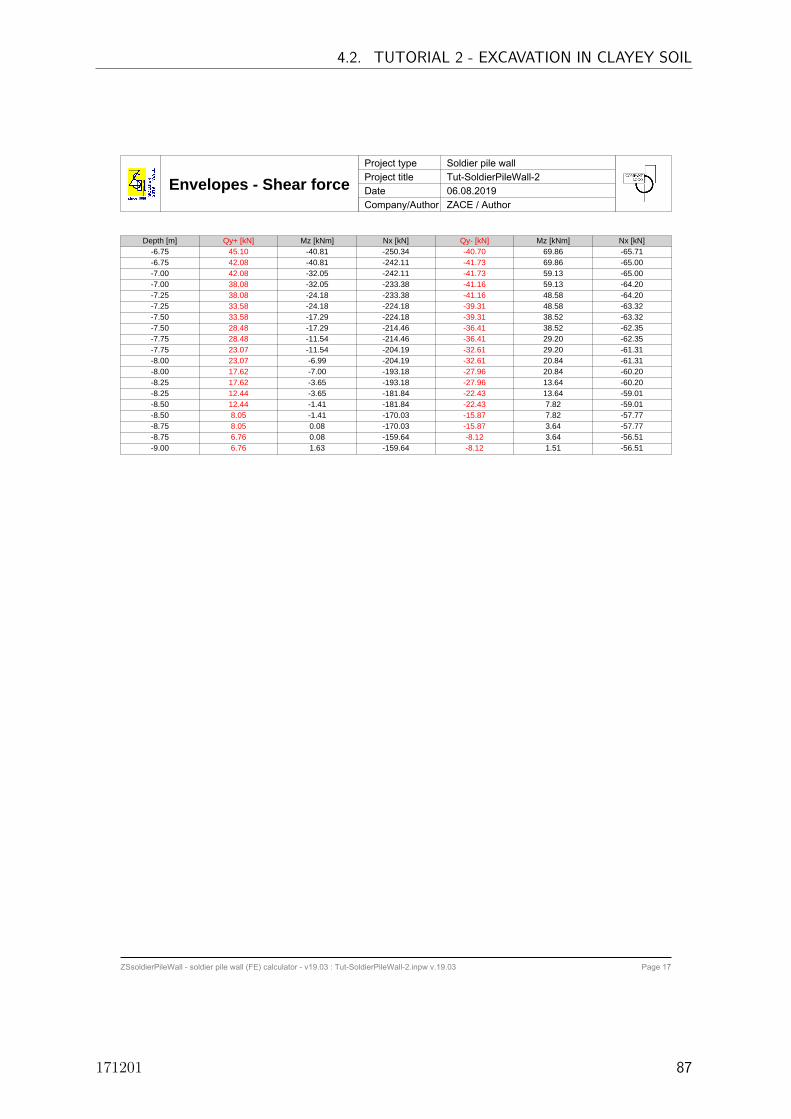
Envelopes - Shear forceProject type Soldier pile wallProject title Tut-SoldierPileWall-2Date 06.08.2019Company/Author ZACE / Author
ZSsoldierPileWall - soldier pile wall (FE) calculator - v19.03 : Tut-SoldierPileWall-2.inpw v.19.03 Page 17
Depth [m] Qy+ [kN] Mz [kNm] Nx [kN] Qy- [kN] Mz [kNm] Nx [kN]-6.75 45.10 -40.81 -250.34 -40.70 69.86 -65.71-6.75 42.08 -40.81 -242.11 -41.73 69.86 -65.00-7.00 42.08 -32.05 -242.11 -41.73 59.13 -65.00-7.00 38.08 -32.05 -233.38 -41.16 59.13 -64.20-7.25 38.08 -24.18 -233.38 -41.16 48.58 -64.20-7.25 33.58 -24.18 -224.18 -39.31 48.58 -63.32-7.50 33.58 -17.29 -224.18 -39.31 38.52 -63.32-7.50 28.48 -17.29 -214.46 -36.41 38.52 -62.35-7.75 28.48 -11.54 -214.46 -36.41 29.20 -62.35-7.75 23.07 -11.54 -204.19 -32.61 29.20 -61.31-8.00 23.07 -6.99 -204.19 -32.61 20.84 -61.31-8.00 17.62 -7.00 -193.18 -27.96 20.84 -60.20-8.25 17.62 -3.65 -193.18 -27.96 13.64 -60.20-8.25 12.44 -3.65 -181.84 -22.43 13.64 -59.01-8.50 12.44 -1.41 -181.84 -22.43 7.82 -59.01-8.50 8.05 -1.41 -170.03 -15.87 7.82 -57.77-8.75 8.05 0.08 -170.03 -15.87 3.64 -57.77-8.75 6.76 0.08 -159.64 -8.12 3.64 -56.51-9.00 6.76 1.63 -159.64 -8.12 1.51 -56.51
4.2. TUTORIAL 2 - EXCAVATION IN CLAYEY SOIL
171201 87

Envelopes - Axial forceProject type Soldier pile wallProject title Tut-SoldierPileWall-2Date 06.08.2019Company/Author ZACE / Author
ZSsoldierPileWall - soldier pile wall (FE) calculator - v19.03 : Tut-SoldierPileWall-2.inpw v.19.03 Page 18
Axial force with corresponding Shear force and Bending momentDepth [m] Nx+ [kN] Qy [kN] Mz [kNm] Nx- [kN] Qy [kN] Mz [kNm]
-0.00 0.00 0.00 0.00 -2.46 -0.49 0.00-0.23 0.00 0.00 0.00 -2.46 -0.49 0.00-0.23 0.00 0.00 0.00 -5.16 0.03 0.00-0.47 0.00 0.00 0.00 -5.16 0.03 0.00-0.47 0.00 0.00 0.00 -8.80 16.81 0.00-0.70 0.00 0.00 0.00 -8.80 16.81 0.00-0.70 0.00 0.00 0.00 -13.11 24.41 0.00-0.93 0.00 0.00 0.00 -13.11 24.41 0.00-0.93 0.00 0.00 0.00 -17.94 33.77 0.00-1.17 0.00 0.00 0.00 -17.94 33.77 0.00-1.17 0.00 0.00 0.00 -22.98 44.03 0.00-1.40 0.00 0.00 0.00 -22.98 44.03 0.00-1.40 0.00 0.00 0.00 -28.21 53.45 0.00-1.63 0.00 0.00 0.00 -28.21 53.45 0.00-1.63 0.00 0.00 0.00 -33.81 64.83 0.00-1.87 0.00 0.00 0.00 -33.81 64.83 0.00-1.87 0.00 0.00 0.00 -39.55 76.67 0.00-2.10 0.00 0.00 0.00 -39.55 76.67 0.00-2.10 0.00 0.00 0.00 -44.84 86.82 0.00-2.33 0.00 0.00 0.00 -44.84 86.82 0.00-2.33 0.00 0.00 0.00 -50.68 100.11 0.00-2.57 0.00 0.00 0.00 -50.68 100.11 0.00-2.57 0.00 0.00 0.00 -57.08 114.76 0.00-2.80 0.00 0.00 0.00 -57.08 114.76 0.00-2.80 0.00 0.00 0.00 -82.48 83.89 0.00-3.03 0.00 0.00 0.00 -82.48 83.89 0.00-3.03 0.00 0.00 0.00 -207.80 -164.43 0.00-3.27 0.00 0.00 0.00 -207.80 -164.43 0.00-3.27 0.00 0.00 0.00 -209.13 -148.83 0.00-3.50 0.00 0.00 0.00 -209.13 -148.83 0.00-3.50 0.00 0.00 0.00 -211.01 -137.84 0.00-3.71 0.00 0.00 0.00 -211.01 -137.84 0.00-3.71 0.00 0.00 0.00 -217.02 -125.62 0.00-3.92 0.00 0.00 0.00 -217.02 -125.62 0.00-3.92 0.00 0.00 0.00 -221.52 -112.13 0.00-4.12 0.00 0.00 0.00 -221.52 -112.13 0.00-4.13 0.00 0.00 0.00 -225.76 -100.32 0.00-4.33 0.00 0.00 0.00 -225.76 -100.32 0.00-4.33 0.00 0.00 0.00 -230.11 -84.41 0.00-4.54 0.00 0.00 0.00 -230.11 -84.41 0.00-4.54 0.00 0.00 0.00 -234.97 -67.76 0.00-4.75 0.00 0.00 0.00 -234.97 -67.76 0.00-4.75 0.00 0.00 0.00 -239.87 -53.57 0.00-4.96 0.00 0.00 0.00 -239.87 -53.57 0.00-4.96 0.00 0.00 0.00 -244.33 -35.35 0.00-5.17 0.00 0.00 0.00 -244.33 -35.35 0.00-5.17 0.00 0.00 0.00 -249.45 -15.51 0.00-5.38 0.00 0.00 0.00 -249.45 -15.51 0.00-5.38 0.00 0.00 0.00 -254.53 0.54 0.00-5.58 0.00 0.00 0.00 -254.53 0.54 0.00-5.58 0.00 0.00 0.00 -258.97 21.19 0.00-5.79 0.00 0.00 0.00 -258.97 21.19 0.00-5.79 0.00 0.00 0.00 -263.81 39.21 0.00-6.00 0.00 0.00 0.00 -263.81 39.21 0.00-6.00 0.00 0.00 0.00 -263.90 43.45 0.00-6.25 0.00 0.00 0.00 -263.90 43.45 0.00-6.25 0.00 0.00 0.00 -257.76 46.15 0.00-6.50 0.00 0.00 0.00 -257.76 46.15 0.00-6.50 0.00 0.00 0.00 -250.34 45.10 0.00
ZSsoldierPileWall - USER GUIDE
88

Envelopes - Axial forceProject type Soldier pile wallProject title Tut-SoldierPileWall-2Date 06.08.2019Company/Author ZACE / Author
ZSsoldierPileWall - soldier pile wall (FE) calculator - v19.03 : Tut-SoldierPileWall-2.inpw v.19.03 Page 19
Depth [m] Nx+ [kN] Qy [kN] Mz [kNm] Nx- [kN] Qy [kN] Mz [kNm]-6.75 0.00 0.00 0.00 -250.34 45.10 0.00-6.75 0.00 0.00 0.00 -242.11 42.08 0.00-7.00 0.00 0.00 0.00 -242.11 42.08 0.00-7.00 0.00 0.00 0.00 -233.38 38.08 0.00-7.25 0.00 0.00 0.00 -233.38 38.08 0.00-7.25 0.00 0.00 0.00 -224.18 33.58 0.00-7.50 0.00 0.00 0.00 -224.18 33.58 0.00-7.50 0.00 0.00 0.00 -214.46 28.48 0.00-7.75 0.00 0.00 0.00 -214.46 28.48 0.00-7.75 0.00 0.00 0.00 -204.19 23.07 0.00-8.00 0.00 0.00 0.00 -204.19 23.07 0.00-8.00 0.00 0.00 0.00 -193.34 17.62 0.00-8.25 0.00 0.00 0.00 -193.34 17.62 0.00-8.25 0.00 0.00 0.00 -181.99 12.42 0.00-8.50 0.00 0.00 0.00 -181.99 12.42 0.00-8.50 0.00 0.00 0.00 -170.17 8.01 0.00-8.75 0.00 0.00 0.00 -170.17 8.01 0.00-8.75 0.00 0.00 0.00 -159.76 6.72 0.00-9.00 0.00 0.00 0.00 -159.76 6.72 0.00
4.2. TUTORIAL 2 - EXCAVATION IN CLAYEY SOIL
171201 89

Envelopes of bendingmoments in lagging
Project type Soldier pile wallProject title Tut-SoldierPileWall-2Date 06.08.2019Company/Author ZACE / Author
ZSsoldierPileWall - soldier pile wall (FE) calculator - v19.03 : Tut-SoldierPileWall-2.inpw v.19.03 Page 20
X - horizontal direction, (-) fibers on excavation sideM-XX-MIN [kNm/m] M-XX-MAX [kNm/m]
ZSsoldierPileWall - USER GUIDE
90
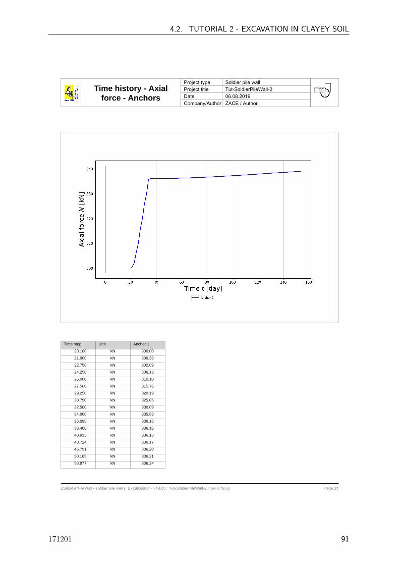
Time history - Axialforce - Anchors
Project type Soldier pile wallProject title Tut-SoldierPileWall-2Date 06.08.2019Company/Author ZACE / Author
ZSsoldierPileWall - soldier pile wall (FE) calculator - v19.03 : Tut-SoldierPileWall-2.inpw v.19.03 Page 21
Time step Unit Anchor 1
20.100 kN 300.00
21.000 kN 300.33
22.750 kN 302.09
24.250 kN 306.13
26.000 kN 310.10
27.500 kN 315.76
29.250 kN 320.19
30.750 kN 325.85
32.500 kN 330.09
34.000 kN 335.83
36.095 kN 336.16
38.400 kN 336.16
40.935 kN 336.18
43.724 kN 336.17
46.791 kN 336.20
50.165 kN 336.21
53.877 kN 336.24
4.2. TUTORIAL 2 - EXCAVATION IN CLAYEY SOIL
171201 91

Time history - Axialforce - Anchors
Project type Soldier pile wallProject title Tut-SoldierPileWall-2Date 06.08.2019Company/Author ZACE / Author
ZSsoldierPileWall - soldier pile wall (FE) calculator - v19.03 : Tut-SoldierPileWall-2.inpw v.19.03 Page 22
Time step Unit Anchor 1
57.960 kN 336.29
62.451 kN 336.37
67.391 kN 336.45
72.826 kN 336.57
78.803 kN 336.70
85.379 kN 336.86
92.612 kN 337.07
100.568 kN 337.31
109.320 kN 337.58
118.947 kN 337.91
129.537 kN 338.29
141.186 kN 338.66
154.000 kN 339.09
154.000 kN 339.19
ZSsoldierPileWall - USER GUIDE
92

References
REFERENCES
[1] T. Benz. Small-strain stiffness of soils and its numerical consequences. Phd, Universitat Sttutgart, 2007.2
[2] F. Kulhawy and P. Mayne. Manual on estimating soil properties for foundation design. Technical report,Electric Power Research Institute (EPRI), 1980. 3
[3] R. Obrzud and A. Truty. The hardening soil model - a practical guidebook. Technical Report Technicalreport ZSoil.PC 100701, Zace Sevices Ltd, 2012. 2
[4] T. Schanz. Zur modellierung des mechanischen verhaltens von reibungsmaterialien. Mitt. Inst. fA¼rGeotechnik, Universitat Stuttgart, 1998, 45, 1998. 2
[5] T. Schanz, P. Vermeer, and P. Bonier, editors. Formulation and verification of the Hardening Soil model.Beyond 2000 in Computational Geotechnics. Balkema, Rotterdam, 1999. 2
[6] M. van Genuchten. A closed-form equation for predicting the hydraulic conductivity of unsaturated soils.Soil Sci. Soc. Am. J, 44:892–898, 1980. 2
[7] ZSoil. User manual ZSoil.PC v2018, Soil, Rock and Structural Mechanics in dry or partially saturatedmedia. ZACE Services Ltd, Software Engineering, Lausanne, Switzerland, 1985-2018. 1, 2