zudar - final stability booklet
TRANSCRIPT

ZUDAR
FINAL STABILITY BOOKLET
FOR PILOT BOAT
CREATE BY: Jakub Handke
SHIP PROJECT Wojciech Kotłowski
ul. Łucznicza 15/5
71-472 Szczecin
POLAND
CHECKED BY: Wojciech Kotłowski
LATEST AMENDMENT: 22-May-17
DOCUMENT NUMBER -
REVISION NUMBER: -A
Rev A – Hydrostatic for trim +/- 0,25m added
LR001.1.2013.12
EXAMINED
This plan has been examined and given the status as shown in the Design Appraisal Document (DAD) number below:
Date: Initials:
Marine, Hamburg Technical Support Office Statutory - STAT
HTS/STAT 28586-17June-06, 2017 KWo
Lloyd's Register EMEA

This is a copy of an electronic document. In the event of any conflict or ambiguity between the copy and the electronic document,which is retained and published by Lloyd's Register, the original electronic and certified version shall always prevail.
LR No. 8683080
STATEMENT OF COMPLIANCE Ship Name: ZUDAR Shipbuilder: Ostsee-Werft K.Vertens GMBH, year of refit 2016 Yard Number: - This is to certify:
STABILITY INFORMATION The stability information contained in the Final Stability Booklet: FINAL STABILITY BOOKLET ZUDAR dated 22 May 2017 Has been examined in accordance with: The 2008 IS Code – International Code on Intact Stability And found to comply. THE PROVISION OF ADEQUATE STABILITY, AT ALL TIMES, REMAINS THE MASTER'S RESPONSIBILITY. No alteration or revision shall be made to any part of this document without prior approval by Lloyd’s Register. Number of pages: .58 + Appendix Signed: Klaas Wolters for Lloyd's Register EMEA Place: Hamburg Date: 06 June 2017
Lloyd's Register, its affiliates and subsidiaries and their respective officers, employees or agents are, individually and collectively, referred to in this clause as the ‘Lloyd's Register Group’. The Lloyd's Register Group assumes no responsibility and shall not be liable to any person for any loss, damage or expense caused by reliance on the information or advice in this document or howsoever provided, unless that person has signed a contract with the relevant Lloyd's Register Group entity for the provision of this information or advice and in that case any responsibility or liability is exclusively on the terms and conditions set out in that contract.
LR031.1.2013.12
Lloyd's Register EMEA
Klaas WoltersHamburg Technical Support Office
This is a copy of an electronic document. In the event of any conflict or ambiguity between the copy and the electronic document,which is retained and published by Lloyd's Register, the original electronic and certified version shall always prevail.
FINAL ACCEPTANCE OF ACTUAL ITEM(S) DEPEND(S) ON SATISFACTORY SURVEY AND TESTING
Lloyd's Register EMEA
Is a member of Lloyd’s Register group
Lloyd's Register Group Limited, its affiliates and subsidiaries and their respective officers, employees or agents are, individually and collectively, referred to in this clause as
'Lloyd's Register'. Lloyd's Register assumes no responsibility and shall not be liable to any person for any loss, damage or expense caused by reliance on the information or
advice in this document or howsoever provided, unless that person has signed a contract with the relevant Lloyd's Register entity for the provision of this information or
advice and in that case any responsibility or liability is exclusively on the terms and conditions set out in that contract.
Form 6438MARCHN (2016.05)
Document no: HTS/STAT 28586-17
Issue number 00
Page 1 of 3
Design Appraisal Document
Lloyd's Register EMEA Date
Hamburg Technical Support Office 06 June 2017
Am Sandtorkai 41
20457 Hamburg Quote this reference on all future communications
Telephone +49 (0)40 328107 - 0 Fax +49 (0)40 328107 - 480 HPC/1750054/28586-17/KWo
E-mail: [email protected]
Lotsbetrieb GmbH MV
Pilot Vessel – ZUDAR
IMO 8683080
Final Stability Booklet
Flag: Germany
1. The document(s) listed in paragraph 1 of the appendix has/have been examined for compliance
with:
The 2008 IS Code – International Code on Intact Stability
and has been found to comply from stability aspects in conjunction with the moulded summer
draught of 1.239m. Further it has been assigned an approval status as indicated in the appendix
and subject to the following comments:-
2. Stability Booklet
2.1 The sea-going loading conditions have been examined for compliance with the applicable stability
criteria and have been found to meet the requirements.
2.2 The provision of adequate stability remains the Master’s responsibility, at all times.
2.3 This appraisal document is to be kept on board together with the approved final stability booklet.
2.4 It is assumed that there are no down-flooding points other than the relevant openings listed
under para 2.2. of the approved document listed under paragraph 1 of the appendix.
2.5 The vessel is allowed to operate under the sea going loading conditions shown in the Stability
Booklet. Any further loading condition under which the vessel intends to operate need to be
calculated and checked in terms of intact stability.
2.6 Compliance with the IMO weather criterion according to the 2008 IS code Part A, Ch. 2, 2.3.1.2.
is not demonstrated.
2.7 No alteration or revision shall be made to any part of the listed document(s) without prior
approval by Lloyd’s Register.
2.8 The KG limit curves listed under chapter 5 of the approved document listed under paragraph 1 of
the appendix, have not been verified and are filed for information only.

This is a copy of an electronic document. In the event of any conflict or ambiguity between the copy and the electronic document,which is retained and published by Lloyd's Register, the original electronic and certified version shall always prevail.
Document no: HTS/STAT 28586-17
Issue number 00
Page 2 of 3
Lloyd's Register EMEA Date
Hamburg Technical Support Office 06 June 2017
Am Sandtorkai 41
20457 Hamburg Quote this reference on all future communications
Telephone +49 (0)40 328107 - 0 Fax +49 (0)40 328107 - 480 HPC/1750054/28586-17/KWo
E-mail: [email protected]
FINAL ACCEPTANCE OF ACTUAL ITEM(S) DEPEND(S) ON SATISFACTORY SURVEY AND TESTING
Lloyd's Register EMEA
Is a member of Lloyd’s Register group
Lloyd's Register Group Limited, its affiliates and subsidiaries and their respective officers, employees or agents are, individually and collectively, referred to in this clause as
'Lloyd's Register'. Lloyd's Register assumes no responsibility and shall not be liable to any person for any loss, damage or expense caused by reliance on the information or
advice in this document or howsoever provided, unless that person has signed a contract with the relevant Lloyd's Register entity for the provision of this information or
advice and in that case any responsibility or liability is exclusively on the terms and conditions set out in that contract.
Form 6438CHN (2016.05)
3. Light ship details (based on inclining experiment)
3.1 The appraisal is based on the following lightship particulars:
Light ship weight: 23.270 tonnes
Longitudinal centre of gravity (LCG): 6.510 meters fwd. of AP
Vertical centre of gravity (VCG): 1.810 meters above BL
Transversal centre of gravity (TCG): 0.000 meters at CL
Klaas Wolters Specialist Statutory Services Hamburg Technical Support Office Lloyd's Register EMEA T +49 (0)40 328107-137 E [email protected]
Delete page break if only one page is required.
LR031.1.2013.12
Lloyd's Register EMEA
Klaas WoltersHamburg Technical Support Office

This is a copy of an electronic document. In the event of any conflict or ambiguity between the copy and the electronic document,which is retained and published by Lloyd's Register, the original electronic and certified version shall always prevail.
Document no: HTS/STAT 28586-17
Issue number 00
Page 3 of 3
Lloyd's Register EMEA Date
Hamburg Technical Support Office 06 June 2017
Am Sandtorkai 41
20457 Hamburg Quote this reference on all future communications
Telephone +49 (0)40 328107 - 0 Fax +49 (0)40 328107 - 480 HPC/1750054/28586-17/KWo
E-mail: [email protected]
Appendix
FINAL ACCEPTANCE OF ACTUAL ITEM(S) DEPEND(S) ON SATISFACTORY SURVEY AND TESTING
Lloyd's Register EMEA
Is a member of Lloyd’s Register group
Lloyd's Register Group Limited, its affiliates and subsidiaries and their respective officers, employees or agents are, individually and collectively, referred to in this clause as
'Lloyd's Register'. Lloyd's Register assumes no responsibility and shall not be liable to any person for any loss, damage or expense caused by reliance on the information or
advice in this document or howsoever provided, unless that person has signed a contract with the relevant Lloyd's Register entity for the provision of this information or
advice and in that case any responsibility or liability is exclusively on the terms and conditions set out in that contract.
Form 6438CHN (2016.05)
1. The documents listed below have been examined
Document No. Rev. Title Status Date
(2017-05-22) A Final Stability Booklet B 06-Jun-2017
2. The documents listed below have been considered together with the submitted documents in the appraisal
Document No. Rev. Title
(2017-05-30) A Hydrostatic Data
Appraisal Status Key
B Examined and amended for compliance with the rule s and regulations as stated under item 1. Of this DAD

ZUDAR - Stability Booklet
2
TABLE OF CONTENTS
Table of Contents ................................................................................................................................................................................ 2
1. Compulsory Information ............................................................................................................................................................ 4
1.1. General ship description.................................................................................................................................................... 4
1.2. Use of the booklet ............................................................................................................................................................. 4
1.3. Master’s shipboard procedures ........................................................................................................................................ 5
1.4. Special notes...................................................................................................................................................................... 7
2. Vessel description ...................................................................................................................................................................... 8
2.1. Frame of reference (and metric conversions) ................................................................................................................... 8
2.2. Key points .......................................................................................................................................................................... 8
2.3. Fluid densities in use ......................................................................................................................................................... 8
3. Stability Criteria .......................................................................................................................................................................... 9
4. Tanks and Compartments ........................................................................................................................................................ 10
4.1. Tanks .......................................................................................................................................................................... 10
5. KG LIMITING ............................................................................................................................................................................. 13
5.1. Limiting KG - trim -0,25m (by bow) ............................................................................................................................. 13
5.2. Limiting KG - trim -0,2m (by bow) ............................................................................................................................... 14
5.3. Limiting KG - trim -0,15m (by bow) ............................................................................................................................. 15
5.4. Limiting KG - trim -0,1m (by bow) ............................................................................................................................... 16
5.5. Limiting KG - trim -0,05m (by bow) ............................................................................................................................. 17
5.6. Limiting KG - trim 0..................................................................................................................................................... 18
5.7. Limiting KG - trim 0,05m (by stern) ............................................................................................................................. 19
5.8. Limiting KG - trim 0,1m (by stern) ............................................................................................................................... 20
5.9. Limiting KG - trim 0,15m (by stern) ............................................................................................................................. 21
5.10. Limiting KG - trim 0,2m (by stern) ............................................................................................................................... 22
1.1. Limiting KG - trim 0,25m (by stern) ............................................................................................................................. 23
6. Stability Loading Conditions ..................................................................................................................................................... 24
6.1. SUMARY LOADING CONDITIONS ..................................................................................................................................... 24
6.2. Standard Loadcases ......................................................................................................................................................... 25
6.2.1. Lightship – not sea going condition ................................................................................................................... 25
6.2.2. Departure 100% of Consumables – sea going condition ............................................................................... 27
6.2.3. Midway 50% of Consumables – sea going condition ..................................................................................... 29
6.2.4. Arrival 10% of Consumables – sea going condition ....................................................................................... 31
7. Hydrostatics Data ..................................................................................................................................................................... 33
7.2. Hydrostatics VALUES ....................................................................................................................................................... 33
7.2.1. Hydrostatics – trim -0,25m (by bow) ...................................................................................................................... 33
7.2.2. Hydrostatics – trim -0,2m (by bow) ........................................................................................................................ 35
7.2.3. Hydrostatics - trim -0,15m (by bow) ....................................................................................................................... 37
7.2.4. Hydrostatics - trim -0,1m (by bow) ......................................................................................................................... 39
7.2.5. Hydrostatics - trim -0,05m (by bow) ....................................................................................................................... 41

ZUDAR - Stability Booklet
3
7.2.6. Hydrostatics - trim 0m ............................................................................................................................................ 43
7.2.7. Hydrostatics - trim 0,05m (by stern) ....................................................................................................................... 45
7.2.8. Hydrostatics - trim 0,1m (by stern) ......................................................................................................................... 47
7.2.9. Hydrostatics - trim 0,15m (by stern) ....................................................................................................................... 49
7.2.10. Hydrostatics - trim 0,2m (by stern) ......................................................................................................................... 51
7.2.1. Hydrostatics - trim 0,25m (by stern) ....................................................................................................................... 53
8. Tank Calibrations ...................................................................................................................................................................... 55
8.1. Tank Calibrations - Fuel ............................................................................................................................................... 55
8.2. Tank Calibrations - Fresh Water .................................................................................................................................. 56
9. Plans/diagrams to insert in the report ..................................................................................................................................... 57
9.1. Tank Definition: ........................................................................................................................................................... 57
9.2. General Arrangement ................................................................................................................................................. 58

ZUDAR - Stability Booklet
4
1. COMPULSORY INFORMATION
1.1. GENERAL SHIP DESCRIPTION
Ship Name ZUDAR
IMO Number 8683080
International Call Sign DKCL2
Owners Lotsbetrieb GmbH MV
Builders Ostsee-Werft K.Vertens G.m.b.H
Year of conversion 2016
Year of build 1983
Length overall 17,30m
Breadth, moulded 4,10m
Depth, moulded 2,07m
Class Society Lloyd's Register
Flag State Germany
Building Number -
1.2. USE OF THE BOOKLET
This stability booklet comprises part of the ship’s data and must be kept on board the vessel at all times. It must be complete,
legible and readily available for use. If this booklet should be lost or become unusable, a replacement copy must be obtained
immediately. This handbook remains valid until revoked by a subsequent handbook or directive.
The loading conditions shown in this booklet represent typical service conditions. It is emphasised that a separate calculation is
necessary for all differing conditions of loading. Master’s Shipboard procedures are to be followed at all times.
ZUDAR - Stability Booklet
5
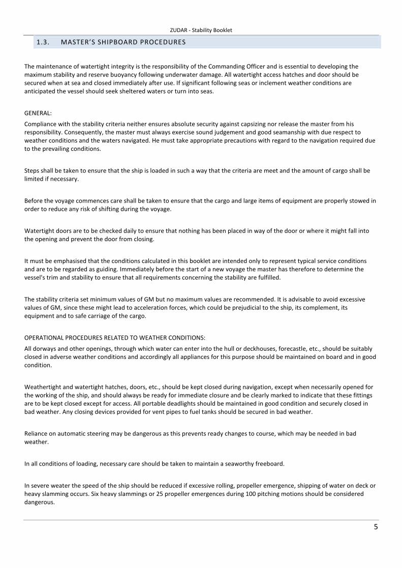
1.3. MASTER’S SHIPBOARD PROCEDURES
The maintenance of watertight integrity is the responsibility of the Commanding Officer and is essential to developing the
maximum stability and reserve buoyancy following underwater damage. All watertight access hatches and door should be
secured when at sea and closed immediately after use. If significant following seas or inclement weather conditions are
anticipated the vessel should seek sheltered waters or turn into seas.
GENERAL:
Compliance with the stability criteria neither ensures absolute security against capsizing nor release the master from his
responsibility. Consequently, the master must always exercise sound judgement and good seamanship with due respect to
weather conditions and the waters navigated. He must take appropriate precautions with regard to the navigation required due
to the prevailing conditions.
Steps shall be taken to ensure that the ship is loaded in such a way that the criteria are meet and the amount of cargo shall be
limited if necessary.
Before the voyage commences care shall be taken to ensure that the cargo and large items of equipment are properly stowed in
order to reduce any risk of shifting during the voyage.
Watertight doors are to be checked daily to ensure that nothing has been placed in way of the door or where it might fall into
the opening and prevent the door from closing.
It must be emphasised that the conditions calculated in this booklet are intended only to represent typical service conditions
and are to be regarded as guiding. Immediately before the start of a new voyage the master has therefore to determine the
vessel's trim and stability to ensure that all requirements concerning the stability are fulfilled.
The stability criteria set minimum values of GM but no maximum values are recommended. It is advisable to avoid excessive
values of GM, since these might lead to acceleration forces, which could be prejudicial to the ship, its complement, its
equipment and to safe carriage of the cargo.
OPERATIONAL PROCEDURES RELATED TO WEATHER CONDITIONS:
All dorways and other openings, through which water can enter into the hull or deckhouses, forecastle, etc., should be suitably
closed in adverse weather conditions and accordingly all appliances for this purpose should be maintained on board and in good
condition.
Weathertight and watertight hatches, doors, etc., should be kept closed during navigation, except when necessarily opened for
the working of the ship, and should always be ready for immediate closure and be clearly marked to indicate that these fittings
are to be kept closed except for access. All portable deadlights should be maintained in good condition and securely closed in
bad weather. Any closing devices provided for vent pipes to fuel tanks should be secured in bad weather.
Reliance on automatic steering may be dangerous as this prevents ready changes to course, which may be needed in bad
weather.
In all conditions of loading, necessary care should be taken to maintain a seaworthy freeboard.
In severe weater the speed of the ship should be reduced if excessive rolling, propeller emergence, shipping of water on deck or
heavy slamming occurs. Six heavy slammings or 25 propeller emergences during 100 pitching motions should be considered
dangerous.

ZUDAR - Stability Booklet
6
Special attention should be paid when a ship is sailing in following or quartering seas because dangerous phenomena such as
parametric resonance, broaching to, deductions of stability on the wave crest, and excessive rolling may occur singularly, in
sequence or simultaneously in a multiple combination, creating a threat of capsize. Particularly dangerous is the situation when
the wavelength is of the order of 1.0 to 1.5 ship's length. A ship's speed and/or course should be altered appropriatly to avoid
the abovementioned phenomena.
When cargo is loaded/discharged at sea, great care must be taken to maintain the ship in a stable condition. The trim limitation
and minimum freeboard requirements should be maintained.
When liquid cargo is to be discharged, as soon as pumping commences a full free surface will exist in those tanks being pumped
and effect of this on the stability should be taken into account;
Deck Cargo Securing Arrangements
Care should be taken that the disposition of deck cargo or equipment does not impede the operation of doors, hatches or other
weathertight or watertight closures.
When loading deck cargo or equipment, care should be taken to avoid any obstruction of freeing ports or drainage
arrangements.
Before leaving port, care should be taken that the cargo and equipment has been properly stowed and lashed so as to minimise
the possibility of shifting at sea, under the effect of rolling and pitching.
GENERAL PRECAUTIONS AGAINST SHIP SINKING IN CASE OF DAMAGE:
The number of tanks containing slack liquids should be kept to a minimum.
Where port and starboard cargo or service tanks are cross coupled, such connections should be closed at sea to minimise the
reduction in stability.
Compliance with the limits indicated in this booklet does not ensure immunity against capsizing regardless of the
circumstances or absolve the master from his responsibilities. The master should therefore exercise good seamanship having
regards to the season of the year, weather forecast and the navigational zone and should take appropriate action as to speed
and course warranted by the prevailing circumstances.

ZUDAR - Stability Booklet
7
1.4. SPECIAL NOTES
- Tank usage and free surface moments:
Provided a tank is completely filled with liquid no movement of the liquid is possible and the effect on the ship’s stability is
precisely the same as if the tank contained solid material. Immediately a quantity of liquid is withdrawn from the tank the
situation changes completely and the stability of the ship is adversely affected by what is known as the ‘free surface effect’. This
adverse effect on the stability is referred to as a ‘loss in GM’ or as a ‘virtual rise in VCG’ and is calculated as follows:
Loss of GM = Free Surface Mmt Tonnes m/Vessel Displacement(Tonnes) When preparing loading conditions, it is to be noted that free surface effects must be allowed for the maximum number of tanks
which are slack or shortly to become slack in that given loading condition. This will mean that, for departure conditions all main
fuel tanks as well as fresh water tanks are considered to be slack.
The number of slack tanks should be kept to a minimum. Where port and starboard tanks are cross coupled, such connection
should be closed at sea to minimise the reduction in stability. Where ballast tanks are used they should be ‘pressed full’ or
‘empty’ as far as possible. Dirty water in the bilges must be kept to a minimum.
- Gusting conditions:
When sailing in a steady wind the vessel heels to the angle at which the heeling arm curve intersects the GZ curve. When struck
by a gust the heel angle will increase to the intersection of the gust heeling arm curve with the GZ curve. The heeling moment
increases in proportion to the square of the apparent wind speed.
- Calculation of the wind heeling arms:
In the case of the wind pressure based formulation, the wind heeling arm is given by:
where:
is a constant, theoretically unity
is the windage area at height
is the vessel mass
is the wind pressure
is the vertical centre of hydrodynamic resistance to the wind force
In the case of the wind velocity based formulation, the wind heeling arm is given by:
where:
is now effectively an average drag coefficient for the windage area
is the wind speed.
And the other parameters are described as above.
( ))(cos)( φφ n
w g
HhPAaH
∆−=
a
A h
∆
P
H
( ))(cos)(
2
φφ nw g
HhAvaH
∆−=
a
v

ZUDAR - Stability Booklet
8
2. VESSEL DESCRIPTION
2.1. FRAME OF REFERENCE (AND METRIC CONVERSIONS)
The frame of reference is set so that the ship’s characteristics are as follows:
Aft Perpendicular 0 m
Midships 7,75 m
Fwd Perpendicular 15,50 m
Length Between Perpendiculars 15,50 m
Baseline 0 m
The transverse distances are measured from the centerline of the ship, positive on starboard and negative on port. The trim is
measured as the difference between draft at AP and draft at FP; the trim with the stern down is defined as positive. The heel to
starboard is positive, to port is negative.
2.2. KEY POINTS
Name Long. Pos.
m
Offset
m
Height
m
Type
Air Vent PS 2,55 -1,35 2,76 Potential downflooding point
Air Vent SB 2,55 1,35 2,76 Potential downflooding point
Air Vent Aft 0,3 1,6 2,8 Potential downflooding point
2.3. FLUID DENSITIES IN USE
FluidType Nb Fluid Name Relative Density
1 Sea Water 1.025
2 Fresh Water 1.000
3 Diesel 0.850
ZUDAR - Stability Booklet
9
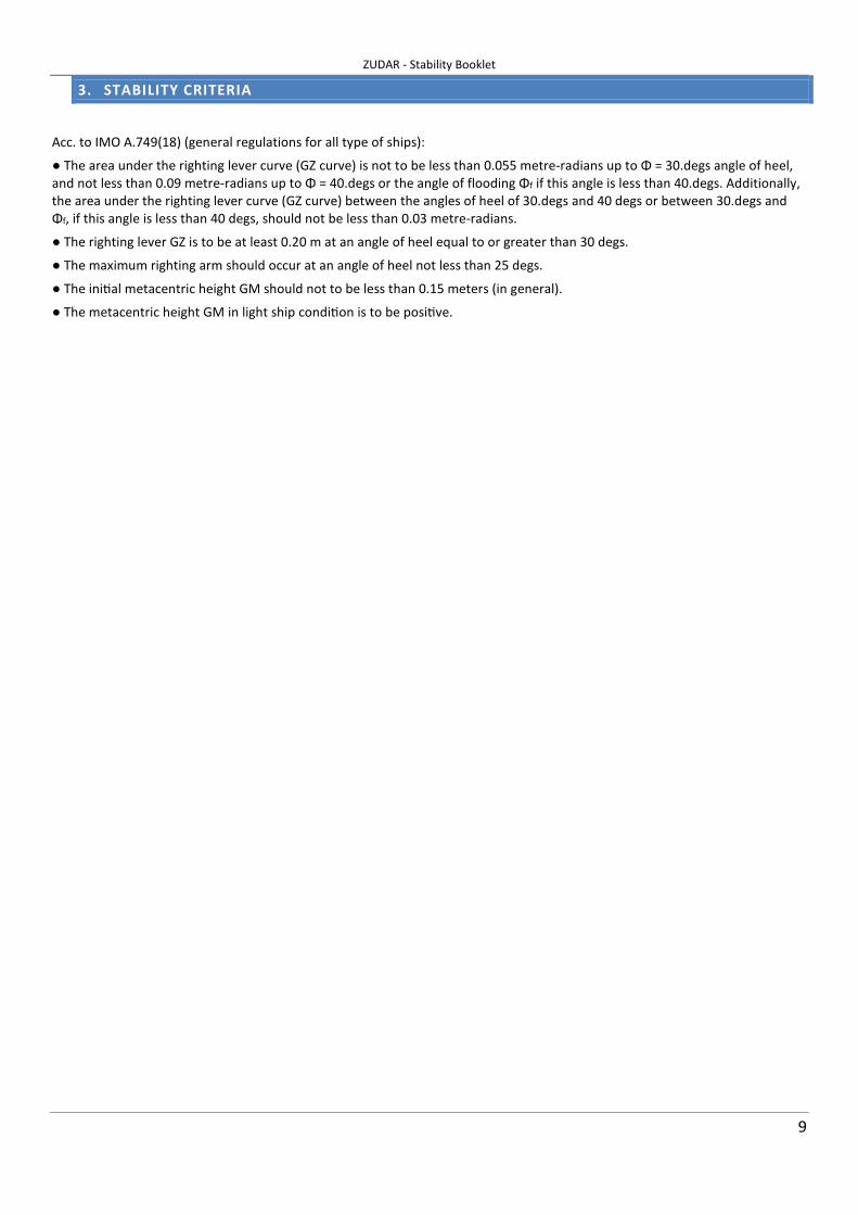
3. STABILITY CRITERIA
Acc. to IMO A.749(18) (general regulations for all type of ships):
● The area under the righting lever curve (GZ curve) is not to be less than 0.055 metre-radians up to Φ = 30.degs angle of heel,
and not less than 0.09 metre-radians up to Φ = 40.degs or the angle of flooding Φf if this angle is less than 40.degs. Additionally,
the area under the righting lever curve (GZ curve) between the angles of heel of 30.degs and 40 degs or between 30.degs and
Φf, if this angle is less than 40 degs, should not be less than 0.03 metre-radians.
● The righting lever GZ is to be at least 0.20 m at an angle of heel equal to or greater than 30 degs.
● The maximum righting arm should occur at an angle of heel not less than 25 degs.
● The ini�al metacentric height GM should not to be less than 0.15 meters (in general).
● The metacentric height GM in light ship condi�on is to be posi�ve.

ZUDAR - Stability Booklet
10
4. TANKS AND COMPARTMENTS
4.1. Tanks

ZUDAR - Stability Booklet
11

ZUDAR - Stability Booklet
12
ZUDAR - Stability Booklet
13
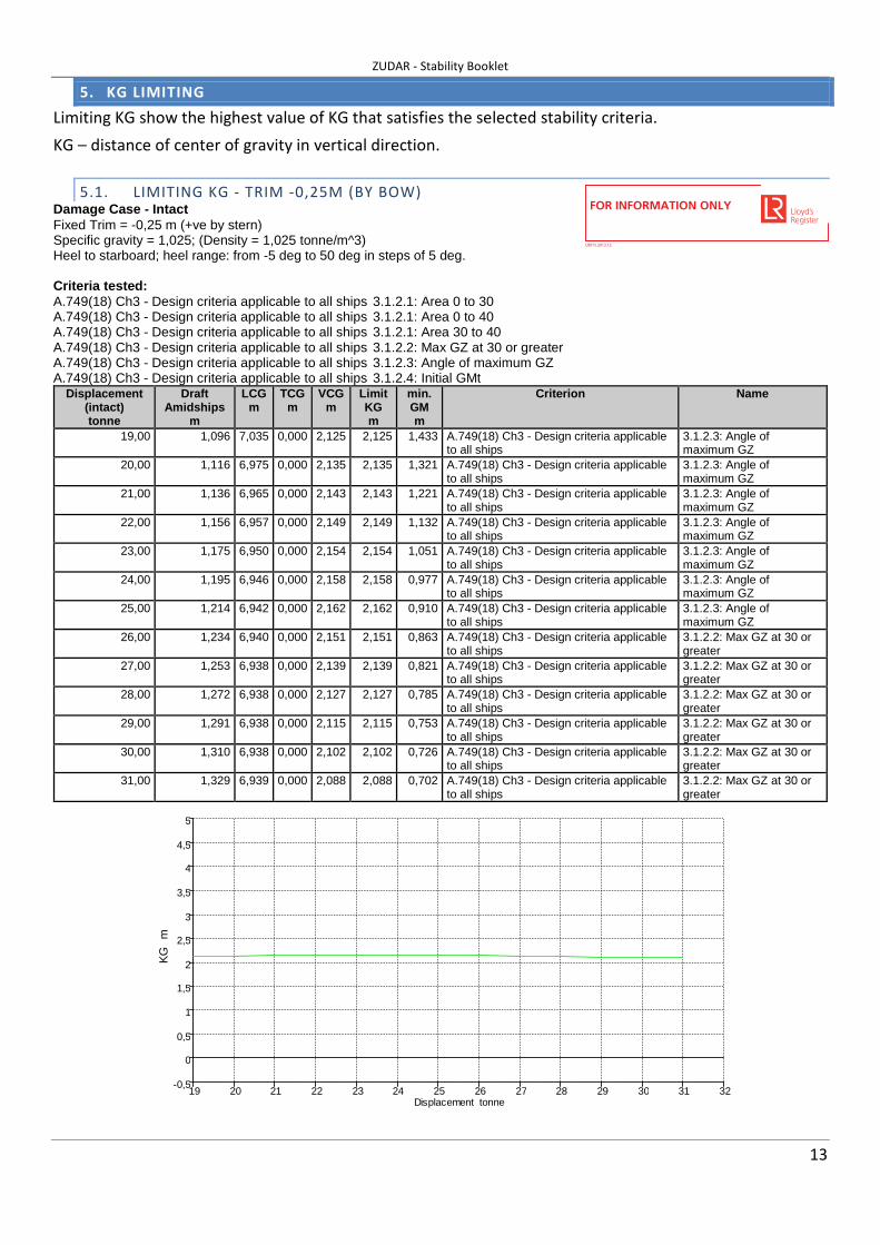
5. KG LIMITING
Limiting KG show the highest value of KG that satisfies the selected stability criteria.
KG – distance of center of gravity in vertical direction.
5.1. LIMITING KG - TRIM -0,25M (BY BOW) Damage Case - Intact Fixed Trim = -0,25 m (+ve by stern) Specific gravity = 1,025; (Density = 1,025 tonne/m^3) Heel to starboard; heel range: from -5 deg to 50 deg in steps of 5 deg. Criteria tested: A.749(18) Ch3 - Design criteria applicable to all ships 3.1.2.1: Area 0 to 30 A.749(18) Ch3 - Design criteria applicable to all ships 3.1.2.1: Area 0 to 40 A.749(18) Ch3 - Design criteria applicable to all ships 3.1.2.1: Area 30 to 40 A.749(18) Ch3 - Design criteria applicable to all ships 3.1.2.2: Max GZ at 30 or greater A.749(18) Ch3 - Design criteria applicable to all ships 3.1.2.3: Angle of maximum GZ A.749(18) Ch3 - Design criteria applicable to all ships 3.1.2.4: Initial GMt
Displacement (intact) tonne
Draft Amidships
m
LCG m
TCG m
VCG m
Limit KG m
min. GM m
Criterion Name
19,00 1,096 7,035 0,000 2,125 2,125 1,433 A.749(18) Ch3 - Design criteria applicable to all ships
3.1.2.3: Angle of maximum GZ
20,00 1,116 6,975 0,000 2,135 2,135 1,321 A.749(18) Ch3 - Design criteria applicable to all ships
3.1.2.3: Angle of maximum GZ
21,00 1,136 6,965 0,000 2,143 2,143 1,221 A.749(18) Ch3 - Design criteria applicable to all ships
3.1.2.3: Angle of maximum GZ
22,00 1,156 6,957 0,000 2,149 2,149 1,132 A.749(18) Ch3 - Design criteria applicable to all ships
3.1.2.3: Angle of maximum GZ
23,00 1,175 6,950 0,000 2,154 2,154 1,051 A.749(18) Ch3 - Design criteria applicable to all ships
3.1.2.3: Angle of maximum GZ
24,00 1,195 6,946 0,000 2,158 2,158 0,977 A.749(18) Ch3 - Design criteria applicable to all ships
3.1.2.3: Angle of maximum GZ
25,00 1,214 6,942 0,000 2,162 2,162 0,910 A.749(18) Ch3 - Design criteria applicable to all ships
3.1.2.3: Angle of maximum GZ
26,00 1,234 6,940 0,000 2,151 2,151 0,863 A.749(18) Ch3 - Design criteria applicable to all ships
3.1.2.2: Max GZ at 30 or greater
27,00 1,253 6,938 0,000 2,139 2,139 0,821 A.749(18) Ch3 - Design criteria applicable to all ships
3.1.2.2: Max GZ at 30 or greater
28,00 1,272 6,938 0,000 2,127 2,127 0,785 A.749(18) Ch3 - Design criteria applicable to all ships
3.1.2.2: Max GZ at 30 or greater
29,00 1,291 6,938 0,000 2,115 2,115 0,753 A.749(18) Ch3 - Design criteria applicable to all ships
3.1.2.2: Max GZ at 30 or greater
30,00 1,310 6,938 0,000 2,102 2,102 0,726 A.749(18) Ch3 - Design criteria applicable to all ships
3.1.2.2: Max GZ at 30 or greater
31,00 1,329 6,939 0,000 2,088 2,088 0,702 A.749(18) Ch3 - Design criteria applicable to all ships
3.1.2.2: Max GZ at 30 or greater
-0,5
0
0,5
1
1,5
2
2,5
3
3,5
4
4,5
5
19 20 21 22 23 24 25 26 27 28 29 30 31 32Displacement tonne
KG
m
LR015.2013.12
FOR INFORMATION ONLY

ZUDAR - Stability Booklet
14
5.2. LIMITING KG - TRIM -0,2M (BY BOW) Damage Case - Intact Fixed Trim = -0,2 m (+ve by stern) Specific gravity = 1,025; (Density = 1,025 tonne/m^3) Heel to starboard; heel range: from -5 deg to 50 deg in steps of 5 deg. Criteria tested: A.749(18) Ch3 - Design criteria applicable to all ships 3.1.2.1: Area 0 to 30 A.749(18) Ch3 - Design criteria applicable to all ships 3.1.2.1: Area 0 to 40 A.749(18) Ch3 - Design criteria applicable to all ships 3.1.2.1: Area 30 to 40 A.749(18) Ch3 - Design criteria applicable to all ships 3.1.2.2: Max GZ at 30 or greater A.749(18) Ch3 - Design criteria applicable to all ships 3.1.2.3: Angle of maximum GZ A.749(18) Ch3 - Design criteria applicable to all ships 3.1.2.4: Initial GMt
Displacement (intact) tonne
Draft Amidships
m
LCG m
TCG m
VCG m
Limit KG m
min. GM m
Criterion Name
19,00 1,093 6,900 0,000 2,118 2,118 1,424 A.749(18) Ch3 - Design criteria applicable to all ships
3.1.2.3: Angle of maximum GZ
20,00 1,113 6,852 0,000 2,128 2,128 1,316 A.749(18) Ch3 - Design criteria applicable to all ships
3.1.2.3: Angle of maximum GZ
21,00 1,133 6,846 0,000 2,137 2,137 1,216 A.749(18) Ch3 - Design criteria applicable to all ships
3.1.2.3: Angle of maximum GZ
22,00 1,153 6,842 0,000 2,145 2,145 1,126 A.749(18) Ch3 - Design criteria applicable to all ships
3.1.2.3: Angle of maximum GZ
23,00 1,172 6,840 0,000 2,152 2,152 1,043 A.749(18) Ch3 - Design criteria applicable to all ships
3.1.2.3: Angle of maximum GZ
24,00 1,192 6,838 0,000 2,159 2,159 0,968 A.749(18) Ch3 - Design criteria applicable to all ships
3.1.2.3: Angle of maximum GZ
25,00 1,212 6,838 0,000 2,165 2,165 0,900 A.749(18) Ch3 - Design criteria applicable to all ships
3.1.2.3: Angle of maximum GZ
26,00 1,231 6,838 0,000 2,172 2,172 0,835 A.749(18) Ch3 - Design criteria applicable to all ships
3.1.2.3: Angle of maximum GZ
27,00 1,250 6,839 0,000 2,181 2,181 0,773 A.749(18) Ch3 - Design criteria applicable to all ships
3.1.2.3: Angle of maximum GZ
28,00 1,269 6,841 0,000 2,187 2,187 0,719 A.749(18) Ch3 - Design criteria applicable to all ships
3.1.2.3: Angle of maximum GZ
29,00 1,289 6,843 0,000 2,187 2,187 0,675 A.749(18) Ch3 - Design criteria applicable to all ships
3.1.2.3: Angle of maximum GZ
30,00 1,308 6,846 0,000 2,177 2,177 0,644 A.749(18) Ch3 - Design criteria applicable to all ships
3.1.2.1: Area 30 to 40
31,00 1,327 6,849 0,000 2,164 2,164 0,620 A.749(18) Ch3 - Design criteria applicable to all ships
3.1.2.1: Area 30 to 40
-0,5
0
0,5
1
1,5
2
2,5
3
3,5
4
4,5
5
19 20 21 22 23 24 25 26 27 28 29 30 31 32Displacement tonne
KG
m
LR015.2013.12
FOR INFORMATION ONLY

ZUDAR - Stability Booklet
15
5.3. LIMITING KG - TRIM -0,15M (BY BOW) Damage Case - Intact Fixed Trim = -0,15 m (+ve by stern) Specific gravity = 1,025; (Density = 1,025 tonne/m^3) Heel to starboard; heel range: from -5 deg to 50 deg in steps of 5 deg. Criteria tested: A.749(18) Ch3 - Design criteria applicable to all ships 3.1.2.1: Area 0 to 30 A.749(18) Ch3 - Design criteria applicable to all ships 3.1.2.1: Area 0 to 40 A.749(18) Ch3 - Design criteria applicable to all ships 3.1.2.1: Area 30 to 40 A.749(18) Ch3 - Design criteria applicable to all ships 3.1.2.2: Max GZ at 30 or greater A.749(18) Ch3 - Design criteria applicable to all ships 3.1.2.3: Angle of maximum GZ A.749(18) Ch3 - Design criteria applicable to all ships 3.1.2.4: Initial GMt
Displacement (intact) tonne
Draft Amidships
m
LCG m
TCG m
VCG m
Limit KG m
min. GM m
Criterion Name
19,00 1,090 6,763 0,000 2,111 2,111 1,416 A.749(18) Ch3 - Design criteria applicable to all ships
3.1.2.3: Angle of maximum GZ
20,00 1,110 6,730 0,000 2,120 2,120 1,310 A.749(18) Ch3 - Design criteria applicable to all ships
3.1.2.3: Angle of maximum GZ
21,00 1,130 6,729 0,000 2,131 2,131 1,211 A.749(18) Ch3 - Design criteria applicable to all ships
3.1.2.3: Angle of maximum GZ
22,00 1,150 6,729 0,000 2,141 2,141 1,120 A.749(18) Ch3 - Design criteria applicable to all ships
3.1.2.3: Angle of maximum GZ
23,00 1,169 6,730 0,000 2,151 2,151 1,035 A.749(18) Ch3 - Design criteria applicable to all ships
3.1.2.3: Angle of maximum GZ
24,00 1,189 6,732 0,000 2,161 2,161 0,958 A.749(18) Ch3 - Design criteria applicable to all ships
3.1.2.3: Angle of maximum GZ
25,00 1,209 6,735 0,000 2,171 2,171 0,885 A.749(18) Ch3 - Design criteria applicable to all ships
3.1.2.3: Angle of maximum GZ
26,00 1,228 6,738 0,000 2,185 2,185 0,816 A.749(18) Ch3 - Design criteria applicable to all ships
3.1.2.3: Angle of maximum GZ
27,00 1,247 6,742 0,000 2,195 2,195 0,753 A.749(18) Ch3 - Design criteria applicable to all ships
3.1.2.3: Angle of maximum GZ
28,00 1,267 6,746 0,000 2,199 2,199 0,700 A.749(18) Ch3 - Design criteria applicable to all ships
3.1.2.3: Angle of maximum GZ
29,00 1,286 6,751 0,000 2,189 2,189 0,667 A.749(18) Ch3 - Design criteria applicable to all ships
3.1.2.1: Area 30 to 40
30,00 1,305 6,756 0,000 2,175 2,175 0,640 A.749(18) Ch3 - Design criteria applicable to all ships
3.1.2.1: Area 30 to 40
31,00 1,324 6,761 0,000 2,162 2,162 0,616 A.749(18) Ch3 - Design criteria applicable to all ships
3.1.2.1: Area 30 to 40
-0,5
0
0,5
1
1,5
2
2,5
3
3,5
4
4,5
5
19 20 21 22 23 24 25 26 27 28 29 30 31 32Displacement tonne
KG
m
LR015.2013.12
FOR INFORMATION ONLY

ZUDAR - Stability Booklet
16
5.4. LIMITING KG - TRIM -0,1M (BY BOW) Damage Case - Intact Fixed Trim = -0,1 m (+ve by stern) Specific gravity = 1,025; (Density = 1,025 tonne/m^3) Heel to starboard; heel range: from -5 deg to 50 deg in steps of 5 deg. Criteria tested: A.749(18) Ch3 - Design criteria applicable to all ships 3.1.2.1: Area 0 to 30 A.749(18) Ch3 - Design criteria applicable to all ships 3.1.2.1: Area 0 to 40 A.749(18) Ch3 - Design criteria applicable to all ships 3.1.2.1: Area 30 to 40 A.749(18) Ch3 - Design criteria applicable to all ships 3.1.2.2: Max GZ at 30 or greater A.749(18) Ch3 - Design criteria applicable to all ships 3.1.2.3: Angle of maximum GZ A.749(18) Ch3 - Design criteria applicable to all ships 3.1.2.4: Initial GMt
Displacement (intact) tonne
Draft Amidships
m
LCG m
TCG m
VCG m
Limit KG m
min. GM m
Criterion Name
19,00 1,086 6,629 0,000 2,104 2,104 1,408 A.749(18) Ch3 - Design criteria applicable to all ships
3.1.2.3: Angle of maximum GZ
20,00 1,106 6,610 0,000 2,112 2,112 1,305 A.749(18) Ch3 - Design criteria applicable to all ships
3.1.2.3: Angle of maximum GZ
21,00 1,126 6,613 0,000 2,125 2,125 1,205 A.749(18) Ch3 - Design criteria applicable to all ships
3.1.2.3: Angle of maximum GZ
22,00 1,146 6,617 0,000 2,139 2,139 1,111 A.749(18) Ch3 - Design criteria applicable to all ships
3.1.2.3: Angle of maximum GZ
23,00 1,166 6,622 0,000 2,152 2,152 1,026 A.749(18) Ch3 - Design criteria applicable to all ships
3.1.2.3: Angle of maximum GZ
24,00 1,186 6,627 0,000 2,166 2,166 0,944 A.749(18) Ch3 - Design criteria applicable to all ships
3.1.2.3: Angle of maximum GZ
25,00 1,206 6,633 0,000 2,182 2,182 0,866 A.749(18) Ch3 - Design criteria applicable to all ships
3.1.2.3: Angle of maximum GZ
26,00 1,225 6,639 0,000 2,198 2,198 0,796 A.749(18) Ch3 - Design criteria applicable to all ships
3.1.2.3: Angle of maximum GZ
27,00 1,245 6,645 0,000 2,207 2,207 0,734 A.749(18) Ch3 - Design criteria applicable to all ships
3.1.2.3: Angle of maximum GZ
28,00 1,264 6,652 0,000 2,202 2,202 0,692 A.749(18) Ch3 - Design criteria applicable to all ships
3.1.2.1: Area 30 to 40
29,00 1,283 6,659 0,000 2,188 2,188 0,662 A.749(18) Ch3 - Design criteria applicable to all ships
3.1.2.1: Area 30 to 40
30,00 1,302 6,667 0,000 2,174 2,174 0,636 A.749(18) Ch3 - Design criteria applicable to all ships
3.1.2.1: Area 30 to 40
31,00 1,321 6,674 0,000 2,160 2,160 0,613 A.749(18) Ch3 - Design criteria applicable to all ships
3.1.2.1: Area 30 to 40
2,1
2,11
2,12
2,13
2,14
2,15
2,16
2,17
2,18
2,19
2,2
2,21
19 20 21 22 23 24 25 26 27 28 29 30 31 32Displacement tonne
KG
m
LR015.2013.12
FOR INFORMATION ONLY

ZUDAR - Stability Booklet
17
5.5. LIMITING KG - TRIM -0,05M (BY BOW) Damage Case - Intact Fixed Trim = -0,05 m (+ve by stern) Specific gravity = 1,025; (Density = 1,025 tonne/m^3) Heel to starboard; heel range: from -5 deg to 50 deg in steps of 5 deg. Criteria tested: A.749(18) Ch3 - Design criteria applicable to all ships 3.1.2.1: Area 0 to 30 A.749(18) Ch3 - Design criteria applicable to all ships 3.1.2.1: Area 0 to 40 A.749(18) Ch3 - Design criteria applicable to all ships 3.1.2.1: Area 30 to 40 A.749(18) Ch3 - Design criteria applicable to all ships 3.1.2.2: Max GZ at 30 or greater A.749(18) Ch3 - Design criteria applicable to all ships 3.1.2.3: Angle of maximum GZ A.749(18) Ch3 - Design criteria applicable to all ships 3.1.2.4: Initial GMt
Displacement (intact) tonne
Draft Amidships
m
LCG m
TCG m
VCG m
Limit KG m
min. GM m
Criterion Name
19,00 1,082 6,495 0,000 2,096 2,096 1,400 A.749(18) Ch3 - Design criteria applicable to all ships
3.1.2.3: Angle of maximum GZ
20,00 1,103 6,492 0,000 2,106 2,106 1,297 A.749(18) Ch3 - Design criteria applicable to all ships
3.1.2.3: Angle of maximum GZ
21,00 1,123 6,499 0,000 2,121 2,121 1,196 A.749(18) Ch3 - Design criteria applicable to all ships
3.1.2.3: Angle of maximum GZ
22,00 1,143 6,506 0,000 2,138 2,138 1,101 A.749(18) Ch3 - Design criteria applicable to all ships
3.1.2.3: Angle of maximum GZ
23,00 1,163 6,514 0,000 2,156 2,156 1,012 A.749(18) Ch3 - Design criteria applicable to all ships
3.1.2.3: Angle of maximum GZ
24,00 1,183 6,523 0,000 2,176 2,176 0,926 A.749(18) Ch3 - Design criteria applicable to all ships
3.1.2.3: Angle of maximum GZ
25,00 1,202 6,532 0,000 2,196 2,196 0,846 A.749(18) Ch3 - Design criteria applicable to all ships
3.1.2.3: Angle of maximum GZ
26,00 1,222 6,541 0,000 2,210 2,210 0,776 A.749(18) Ch3 - Design criteria applicable to all ships
3.1.2.3: Angle of maximum GZ
27,00 1,242 6,550 0,000 2,216 2,216 0,719 A.749(18) Ch3 - Design criteria applicable to all ships
3.1.2.1: Area 30 to 40
28,00 1,261 6,559 0,000 2,201 2,201 0,687 A.749(18) Ch3 - Design criteria applicable to all ships
3.1.2.1: Area 30 to 40
29,00 1,280 6,569 0,000 2,187 2,187 0,658 A.749(18) Ch3 - Design criteria applicable to all ships
3.1.2.1: Area 30 to 40
30,00 1,300 6,578 0,000 2,173 2,173 0,632 A.749(18) Ch3 - Design criteria applicable to all ships
3.1.2.1: Area 30 to 40
31,00 1,319 6,587 0,000 2,158 2,158 0,610 A.749(18) Ch3 - Design criteria applicable to all ships
3.1.2.1: Area 30 to 40
2,08
2,1
2,12
2,14
2,16
2,18
2,2
2,22
19 20 21 22 23 24 25 26 27 28 29 30 31 32Displacement tonne
KG
m
LR015.2013.12
FOR INFORMATION ONLY

ZUDAR - Stability Booklet
18
5.6. LIMITING KG - TRIM 0 Damage Case - Intact Fixed Trim = 0 m (+ve by stern) Specific gravity = 1,025; (Density = 1,025 tonne/m^3) Heel to starboard; heel range: from -5 deg to 50 deg in steps of 5 deg. Criteria tested: A.749(18) Ch3 - Design criteria applicable to all ships 3.1.2.1: Area 0 to 30 A.749(18) Ch3 - Design criteria applicable to all ships 3.1.2.1: Area 0 to 40 A.749(18) Ch3 - Design criteria applicable to all ships 3.1.2.1: Area 30 to 40 A.749(18) Ch3 - Design criteria applicable to all ships 3.1.2.2: Max GZ at 30 or greater A.749(18) Ch3 - Design criteria applicable to all ships 3.1.2.3: Angle of maximum GZ A.749(18) Ch3 - Design criteria applicable to all ships 3.1.2.4: Initial GMt
Displacement (intact) tonne
Draft Amidships
m
LCG m
TCG m
VCG m
Limit KG m
min. GM m
Criterion Name
19,00 1,079 6,364 0,000 2,089 2,089 1,393 A.749(18) Ch3 - Design criteria applicable to all ships
3.1.2.3: Angle of maximum GZ
20,00 1,099 6,374 0,000 2,101 2,101 1,287 A.749(18) Ch3 - Design criteria applicable to all ships
3.1.2.3: Angle of maximum GZ
21,00 1,119 6,386 0,000 2,119 2,119 1,187 A.749(18) Ch3 - Design criteria applicable to all ships
3.1.2.3: Angle of maximum GZ
22,00 1,139 6,397 0,000 2,140 2,140 1,089 A.749(18) Ch3 - Design criteria applicable to all ships
3.1.2.3: Angle of maximum GZ
23,00 1,159 6,409 0,000 2,163 2,163 0,994 A.749(18) Ch3 - Design criteria applicable to all ships
3.1.2.3: Angle of maximum GZ
24,00 1,179 6,420 0,000 2,188 2,188 0,905 A.749(18) Ch3 - Design criteria applicable to all ships
3.1.2.3: Angle of maximum GZ
25,00 1,199 6,432 0,000 2,208 2,208 0,826 A.749(18) Ch3 - Design criteria applicable to all ships
3.1.2.3: Angle of maximum GZ
26,00 1,219 6,444 0,000 2,222 2,222 0,758 A.749(18) Ch3 - Design criteria applicable to all ships
3.1.2.3: Angle of maximum GZ
27,00 1,238 6,456 0,000 2,216 2,216 0,713 A.749(18) Ch3 - Design criteria applicable to all ships
3.1.2.1: Area 30 to 40
28,00 1,258 6,467 0,000 2,200 2,200 0,682 A.749(18) Ch3 - Design criteria applicable to all ships
3.1.2.1: Area 30 to 40
29,00 1,277 6,479 0,000 2,186 2,186 0,654 A.749(18) Ch3 - Design criteria applicable to all ships
3.1.2.1: Area 30 to 40
30,00 1,297 6,490 0,000 2,171 2,171 0,629 A.749(18) Ch3 - Design criteria applicable to all ships
3.1.2.1: Area 30 to 40
31,00 1,316 6,502 0,000 2,157 2,157 0,606 A.749(18) Ch3 - Design criteria applicable to all ships
3.1.2.1: Area 30 to 40
2,08
2,1
2,12
2,14
2,16
2,18
2,2
2,22
2,24
19 20 21 22 23 24 25 26 27 28 29 30 31 32Displacement tonne
KG
m
LR015.2013.12
FOR INFORMATION ONLY

ZUDAR - Stability Booklet
19
5.7. LIMITING KG - TRIM 0,05M (BY STERN) Damage Case - Intact Fixed Trim = 0,05 m (+ve by stern) Specific gravity = 1,025; (Density = 1,025 tonne/m^3) Heel to starboard; heel range: from -5 deg to 50 deg in steps of 5 deg. Criteria tested: A.749(18) Ch3 - Design criteria applicable to all ships 3.1.2.1: Area 0 to 30 A.749(18) Ch3 - Design criteria applicable to all ships 3.1.2.1: Area 0 to 40 A.749(18) Ch3 - Design criteria applicable to all ships 3.1.2.1: Area 30 to 40 A.749(18) Ch3 - Design criteria applicable to all ships 3.1.2.2: Max GZ at 30 or greater A.749(18) Ch3 - Design criteria applicable to all ships 3.1.2.3: Angle of maximum GZ A.749(18) Ch3 - Design criteria applicable to all ships 3.1.2.4: Initial GMt
Displacement (intact) tonne
Draft Amidships
m
LCG m
TCG m
VCG m
Limit KG m
min. GM m
Criterion Name
19,00 1,075 6,234 0,000 2,083 2,083 1,383 A.749(18) Ch3 - Design criteria applicable to all ships
3.1.2.3: Angle of maximum GZ
20,00 1,095 6,259 0,000 2,098 2,098 1,277 A.749(18) Ch3 - Design criteria applicable to all ships
3.1.2.3: Angle of maximum GZ
21,00 1,116 6,274 0,000 2,119 2,119 1,173 A.749(18) Ch3 - Design criteria applicable to all ships
3.1.2.3: Angle of maximum GZ
22,00 1,136 6,289 0,000 2,146 2,146 1,071 A.749(18) Ch3 - Design criteria applicable to all ships
3.1.2.3: Angle of maximum GZ
23,00 1,156 6,304 0,000 2,175 2,175 0,973 A.749(18) Ch3 - Design criteria applicable to all ships
3.1.2.3: Angle of maximum GZ
24,00 1,176 6,319 0,000 2,200 2,200 0,885 A.749(18) Ch3 - Design criteria applicable to all ships
3.1.2.3: Angle of maximum GZ
25,00 1,196 6,334 0,000 2,219 2,219 0,807 A.749(18) Ch3 - Design criteria applicable to all ships
3.1.2.3: Angle of maximum GZ
26,00 1,216 6,348 0,000 2,230 2,230 0,742 A.749(18) Ch3 - Design criteria applicable to all ships
3.1.2.1: Area 30 to 40
27,00 1,235 6,362 0,000 2,215 2,215 0,707 A.749(18) Ch3 - Design criteria applicable to all ships
3.1.2.1: Area 30 to 40
28,00 1,255 6,376 0,000 2,199 2,199 0,677 A.749(18) Ch3 - Design criteria applicable to all ships
3.1.2.1: Area 30 to 40
29,00 1,274 6,390 0,000 2,184 2,184 0,649 A.749(18) Ch3 - Design criteria applicable to all ships
3.1.2.1: Area 30 to 40
30,00 1,294 6,404 0,000 2,169 2,169 0,625 A.749(18) Ch3 - Design criteria applicable to all ships
3.1.2.1: Area 30 to 40
31,00 1,313 6,417 0,000 2,155 2,155 0,604 A.749(18) Ch3 - Design criteria applicable to all ships
3.1.2.1: Area 30 to 40
2,08
2,1
2,12
2,14
2,16
2,18
2,2
2,22
2,24
19 20 21 22 23 24 25 26 27 28 29 30 31 32Displacement tonne
KG
m
LR015.2013.12
FOR INFORMATION ONLY

ZUDAR - Stability Booklet
20
5.8. LIMITING KG - TRIM 0,1M (BY STERN) Damage Case - Intact Fixed Trim = 0,1 m (+ve by stern) Specific gravity = 1,025; (Density = 1,025 tonne/m^3) Heel to starboard; heel range: from -5 deg to 50 deg in steps of 5 deg. Criteria tested: A.749(18) Ch3 - Design criteria applicable to all ships 3.1.2.1: Area 0 to 30 A.749(18) Ch3 - Design criteria applicable to all ships 3.1.2.1: Area 0 to 40 A.749(18) Ch3 - Design criteria applicable to all ships 3.1.2.1: Area 30 to 40 A.749(18) Ch3 - Design criteria applicable to all ships 3.1.2.2: Max GZ at 30 or greater A.749(18) Ch3 - Design criteria applicable to all ships 3.1.2.3: Angle of maximum GZ A.749(18) Ch3 - Design criteria applicable to all ships 3.1.2.4: Initial GMt
Displacement (intact) tonne
Draft Amidships
m
LCG m
TCG m
VCG m
Limit KG m
min. GM m
Criterion Name
19,00 1,071 6,106 0,000 2,080 2,080 1,371 A.749(18) Ch3 - Design criteria applicable to all ships
3.1.2.3: Angle of maximum GZ
20,00 1,091 6,145 0,000 2,098 2,098 1,264 A.749(18) Ch3 - Design criteria applicable to all ships
3.1.2.3: Angle of maximum GZ
21,00 1,112 6,164 0,000 2,124 2,124 1,156 A.749(18) Ch3 - Design criteria applicable to all ships
3.1.2.3: Angle of maximum GZ
22,00 1,132 6,183 0,000 2,156 2,156 1,050 A.749(18) Ch3 - Design criteria applicable to all ships
3.1.2.3: Angle of maximum GZ
23,00 1,152 6,201 0,000 2,187 2,187 0,951 A.749(18) Ch3 - Design criteria applicable to all ships
3.1.2.3: Angle of maximum GZ
24,00 1,172 6,219 0,000 2,212 2,212 0,863 A.749(18) Ch3 - Design criteria applicable to all ships
3.1.2.3: Angle of maximum GZ
25,00 1,192 6,237 0,000 2,230 2,230 0,788 A.749(18) Ch3 - Design criteria applicable to all ships
3.1.2.3: Angle of maximum GZ
26,00 1,212 6,254 0,000 2,230 2,230 0,735 A.749(18) Ch3 - Design criteria applicable to all ships
3.1.2.1: Area 30 to 40
27,00 1,232 6,270 0,000 2,214 2,214 0,702 A.749(18) Ch3 - Design criteria applicable to all ships
3.1.2.1: Area 30 to 40
28,00 1,252 6,286 0,000 2,198 2,198 0,672 A.749(18) Ch3 - Design criteria applicable to all ships
3.1.2.1: Area 30 to 40
29,00 1,271 6,302 0,000 2,183 2,183 0,646 A.749(18) Ch3 - Design criteria applicable to all ships
3.1.2.1: Area 30 to 40
30,00 1,291 6,318 0,000 2,168 2,168 0,622 A.749(18) Ch3 - Design criteria applicable to all ships
3.1.2.1: Area 30 to 40
31,00 1,310 6,333 0,000 2,153 2,153 0,601 A.749(18) Ch3 - Design criteria applicable to all ships
3.1.2.1: Area 30 to 40
2,06
2,08
2,1
2,12
2,14
2,16
2,18
2,2
2,22
2,24
19 20 21 22 23 24 25 26 27 28 29 30 31 32Displacement tonne
KG
m
LR015.2013.12
FOR INFORMATION ONLY

ZUDAR - Stability Booklet
21
5.9. LIMITING KG - TRIM 0,15M (BY STERN) Damage Case - Intact Fixed Trim = 0,15 m (+ve by stern) Specific gravity = 1,025; (Density = 1,025 tonne/m^3) Heel to starboard; heel range: from -5 deg to 50 deg in steps of 5 deg. Criteria tested: A.749(18) Ch3 - Design criteria applicable to all ships 3.1.2.1: Area 0 to 30 A.749(18) Ch3 - Design criteria applicable to all ships 3.1.2.1: Area 0 to 40 A.749(18) Ch3 - Design criteria applicable to all ships 3.1.2.1: Area 30 to 40 A.749(18) Ch3 - Design criteria applicable to all ships 3.1.2.2: Max GZ at 30 or greater A.749(18) Ch3 - Design criteria applicable to all ships 3.1.2.3: Angle of maximum GZ A.749(18) Ch3 - Design criteria applicable to all ships 3.1.2.4: Initial GMt
Displacement (intact) tonne
Draft Amidships
m
LCG m
TCG m
VCG m
Limit KG m
min. GM m
Criterion Name
19,00 1,067 5,979 0,000 2,079 2,079 1,357 A.749(18) Ch3 - Design criteria applicable to all ships
3.1.2.3: Angle of maximum GZ
20,00 1,087 6,032 0,000 2,102 2,102 1,248 A.749(18) Ch3 - Design criteria applicable to all ships
3.1.2.3: Angle of maximum GZ
21,00 1,108 6,055 0,000 2,133 2,133 1,136 A.749(18) Ch3 - Design criteria applicable to all ships
3.1.2.3: Angle of maximum GZ
22,00 1,128 6,078 0,000 2,169 2,169 1,026 A.749(18) Ch3 - Design criteria applicable to all ships
3.1.2.3: Angle of maximum GZ
23,00 1,149 6,099 0,000 2,199 2,199 0,930 A.749(18) Ch3 - Design criteria applicable to all ships
3.1.2.3: Angle of maximum GZ
24,00 1,169 6,120 0,000 2,222 2,222 0,844 A.749(18) Ch3 - Design criteria applicable to all ships
3.1.2.3: Angle of maximum GZ
25,00 1,189 6,141 0,000 2,239 2,239 0,771 A.749(18) Ch3 - Design criteria applicable to all ships
3.1.2.3: Angle of maximum GZ
26,00 1,209 6,160 0,000 2,229 2,229 0,729 A.749(18) Ch3 - Design criteria applicable to all ships
3.1.2.1: Area 30 to 40
27,00 1,229 6,179 0,000 2,213 2,213 0,696 A.749(18) Ch3 - Design criteria applicable to all ships
3.1.2.1: Area 30 to 40
28,00 1,248 6,197 0,000 2,197 2,197 0,668 A.749(18) Ch3 - Design criteria applicable to all ships
3.1.2.1: Area 30 to 40
29,00 1,268 6,215 0,000 2,181 2,181 0,642 A.749(18) Ch3 - Design criteria applicable to all ships
3.1.2.1: Area 30 to 40
30,00 1,287 6,233 0,000 2,166 2,166 0,619 A.749(18) Ch3 - Design criteria applicable to all ships
3.1.2.1: Area 30 to 40
31,00 1,307 6,250 0,000 2,150 2,150 0,599 A.749(18) Ch3 - Design criteria applicable to all ships
3.1.2.1: Area 30 to 40
2,06
2,08
2,1
2,12
2,14
2,16
2,18
2,2
2,22
2,24
19 20 21 22 23 24 25 26 27 28 29 30 31 32Displacement tonne
KG
m
LR015.2013.12
FOR INFORMATION ONLY

ZUDAR - Stability Booklet
22
5.10. LIMITING KG - TRIM 0,2M (BY STERN) Damage Case - Intact Fixed Trim = 0,2 m (+ve by stern) Specific gravity = 1,025; (Density = 1,025 tonne/m^3) Heel to starboard; heel range: from -5 deg to 50 deg in steps of 5 deg. Criteria tested: A.749(18) Ch3 - Design criteria applicable to all ships 3.1.2.1: Area 0 to 30 A.749(18) Ch3 - Design criteria applicable to all ships 3.1.2.1: Area 0 to 40 A.749(18) Ch3 - Design criteria applicable to all ships 3.1.2.1: Area 30 to 40 A.749(18) Ch3 - Design criteria applicable to all ships 3.1.2.2: Max GZ at 30 or greater A.749(18) Ch3 - Design criteria applicable to all ships 3.1.2.3: Angle of maximum GZ A.749(18) Ch3 - Design criteria applicable to all ships 3.1.2.4: Initial GMt
Displacement (intact) tonne
Draft Amidships
m
LCG m
TCG m
VCG m
Limit KG m
min. GM m
Criterion Name
19,00 1,062 5,854 0,000 2,082 2,082 1,340 A.749(18) Ch3 - Design criteria applicable to all ships
3.1.2.3: Angle of maximum GZ
20,00 1,083 5,921 0,000 2,110 2,110 1,225 A.749(18) Ch3 - Design criteria applicable to all ships
3.1.2.3: Angle of maximum GZ
21,00 1,104 5,948 0,000 2,146 2,146 1,111 A.749(18) Ch3 - Design criteria applicable to all ships
3.1.2.3: Angle of maximum GZ
22,00 1,124 5,974 0,000 2,181 2,181 1,005 A.749(18) Ch3 - Design criteria applicable to all ships
3.1.2.3: Angle of maximum GZ
23,00 1,145 5,999 0,000 2,210 2,210 0,909 A.749(18) Ch3 - Design criteria applicable to all ships
3.1.2.3: Angle of maximum GZ
24,00 1,165 6,023 0,000 2,232 2,232 0,827 A.749(18) Ch3 - Design criteria applicable to all ships
3.1.2.3: Angle of maximum GZ
25,00 1,185 6,046 0,000 2,244 2,244 0,758 A.749(18) Ch3 - Design criteria applicable to all ships
3.1.2.1: Area 30 to 40
26,00 1,205 6,068 0,000 2,228 2,228 0,723 A.749(18) Ch3 - Design criteria applicable to all ships
3.1.2.1: Area 30 to 40
27,00 1,225 6,089 0,000 2,212 2,212 0,691 A.749(18) Ch3 - Design criteria applicable to all ships
3.1.2.1: Area 30 to 40
28,00 1,245 6,109 0,000 2,195 2,195 0,663 A.749(18) Ch3 - Design criteria applicable to all ships
3.1.2.1: Area 30 to 40
29,00 1,264 6,129 0,000 2,179 2,179 0,638 A.749(18) Ch3 - Design criteria applicable to all ships
3.1.2.1: Area 30 to 40
30,00 1,284 6,149 0,000 2,164 2,164 0,616 A.749(18) Ch3 - Design criteria applicable to all ships
3.1.2.1: Area 30 to 40
31,00 1,303 6,167 0,000 2,148 2,148 0,596 A.749(18) Ch3 - Design criteria applicable to all ships
3.1.2.1: Area 30 to 40
2,08
2,1
2,12
2,14
2,16
2,18
2,2
2,22
2,24
2,26
19 20 21 22 23 24 25 26 27 28 29 30 31 32Displacement tonne
KG
m
LR015.2013.12
FOR INFORMATION ONLY

ZUDAR - Stability Booklet
23
1.1. LIMITING KG - TRIM 0,25M (BY STERN) Damage Case – Intact
Fixed Trim = 0,25 m (+ve by stern)
Specific gravity = 1,025; (Density = 1,025 tonne/m^3)
Heel to starboard; heel range: from -5 deg to 50 deg in steps of 5 deg.
Criteria tested:
A.749(18) Ch3 - Design criteria applicable to all ships 3.1.2.1: Area 0 to 30
A.749(18) Ch3 - Design criteria applicable to all ships 3.1.2.1: Area 0 to 40
A.749(18) Ch3 - Design criteria applicable to all ships 3.1.2.1: Area 30 to 40
A.749(18) Ch3 - Design criteria applicable to all ships 3.1.2.2: Max GZ at 30 or greater
A.749(18) Ch3 - Design criteria applicable to all ships 3.1.2.3: Angle of maximum GZ
A.749(18) Ch3 - Design criteria applicable to all ships 3.1.2.4: Initial GMt Displacement
(intact) tonne
Draft Amidships
m
LCG m
TCG m
VCG m
Limit KG m
min. GM m
Criterion Name
19,00 1,058 5,731 0,000 2,089 2,089 1,318 A.749(18) Ch3 - Design criteria applicable to all ships
3.1.2.3: Angle of maximum GZ
20,00 1,079 5,812 0,000 2,123 2,123 1,200 A.749(18) Ch3 - Design criteria applicable to all ships
3.1.2.3: Angle of maximum GZ
21,00 1,100 5,843 0,000 2,160 2,160 1,084 A.749(18) Ch3 - Design criteria applicable to all ships
3.1.2.3: Angle of maximum GZ
22,00 1,120 5,872 0,000 2,193 2,193 0,982 A.749(18) Ch3 - Design criteria applicable to all ships
3.1.2.3: Angle of maximum GZ
23,00 1,141 5,900 0,000 2,207 2,207 0,903 A.749(18) Ch3 - Design criteria applicable to all ships
3.1.2.2: Max GZ at 30 or greater
24,00 1,161 5,926 0,000 2,193 2,193 0,856 A.749(18) Ch3 - Design criteria applicable to all ships
3.1.2.2: Max GZ at 30 or greater
25,00 1,181 5,951 0,000 2,178 2,178 0,816 A.749(18) Ch3 - Design criteria applicable to all ships
3.1.2.2: Max GZ at 30 or greater
26,00 1,201 5,975 0,000 2,163 2,163 0,780 A.749(18) Ch3 - Design criteria applicable to all ships
3.1.2.2: Max GZ at 30 or greater
27,00 1,221 5,999 0,000 2,147 2,147 0,749 A.749(18) Ch3 - Design criteria applicable to all ships
3.1.2.2: Max GZ at 30 or greater
28,00 1,241 6,021 0,000 2,130 2,130 0,722 A.749(18) Ch3 - Design criteria applicable to all ships
3.1.2.2: Max GZ at 30 or greater
29,00 1,261 6,043 0,000 2,112 2,112 0,700 A.749(18) Ch3 - Design criteria applicable to all ships
3.1.2.2: Max GZ at 30 or greater
30,00 1,281 6,064 0,000 2,094 2,094 0,681 A.749(18) Ch3 - Design criteria applicable to all ships
3.1.2.2: Max GZ at 30 or greater
31,00 1,300 6,085 0,000 2,075 2,075 0,664 A.749(18) Ch3 - Design criteria applicable to all ships
3.1.2.2: Max GZ at 30 or greater
2,06
2,08
2,1
2,12
2,14
2,16
2,18
2,2
2,22
19 20 21 22 23 24 25 26 27 28 29 30 31 32Displacement tonne
KG
m
LR015.2013.12
FOR INFORMATION ONLY

ZUDAR - Stability Booklet
24
6. STABILITY LOADING CONDITIONS
6.1. SUMARY LOADING CONDITIONS
6.2.1. Lightship – not sea going condition
6.2.2. Departure 100% of Consumables – sea going co ndition
6.2.3. Midway 50% of Consumables – sea going condit ion
6.2.4. Arrival 10% of Consumables – sea going condi tion
DISP
t
FO/FW Draft
Midsh.
m
Draft
FW
m
Draft
AP
m
Trim
m
GM
m
6.2.1. 23,27 0,000 1,168 1,192 1,145 -0,047 1,339
6.2.2. 26,38 2,347 1,239 1,344 1,134 -0,211 1,210
6.2.3. 25,21 1,174 1,212 1,283 1,141 -0,142 1,194
6.2.4. 24,26 0,235 1,190 1,233 1,148 -0,085 1,219

ZUDAR - Stability Booklet
25
6.2. STANDARD LOADCASES
6.2.1. Lightship – not sea going condition Free to Trim; Specific gravity = 1,025; (Density = 1,025 tonne/m^3)
Item Name Quantity Unit Mass tonne
Total Mass tonne
Unit Volume m^3
Total Volume m^3
Long. Arm m
Trans. Arm m
Vert. Arm m
Lightship 1 23,270 23,270 6,510 0,000 1,810 Fuel 0% 2,043 0,000 2,376 0,000 9,660 0,000 0,900 Fresh Water 0% 0,304 0,000 0,304 0,000 11,700 0,011 1,000 Total Loadcase 23,270 2,680 0,000 6,510 0,000 1,810 FS correction 0,000 VCG fluid 1,810
Equilibrium data
Draft Amidships m 1,168 KG fluid m 1,810 Displacement t 23,27 BMt m 2,246 Heel deg 0,0 BML m 33,958 Draft at FP m 1,192 GMt corrected m 1,339 Draft at AP m 1,145 GML m 33,052 Draft at LCF m 1,165 KMt m 3,149 Trim (+ve by stern) m -0,047 KML m 34,862 WL Length m 15,535 Immersion (TPc) tonne/cm 0,504 Beam max extents on WL m 3,820 MTc tonne.m 0,496 LCB from zero pt. (+ve fwd) m 6,514 RM at 1deg = GMt.Disp.sin(1) tonne.m 0,544 LCF from zero pt. (+ve fwd) m 6,716 Max deck inclination deg 0,1737 KB m 0,904 Trim angle (+ve by stern) deg -0,1737

ZUDAR - Stability Booklet
26
Stability Calculation – Heel to Starboard
Heel to Starboard
deg 0,0 5,0 10,0 15,0 20,0 25,0 30,0 35,0 40,0 45,0 50,0
GZ m 0,000 0,117 0,230 0,323 0,385 0,421 0,441 0,439 0,418 0,383 0,342 Area under GZ curve from zero heel m.rad
0,0000 0,0051 0,0203 0,0446 0,0757 0,1111 0,1488 0,1874 0,2249 0,2599 0,2916
KB m 0,904 0,912 0,937 0,975 1,019 1,066 1,117 1,166 1,212 1,256 1,302 KG fluid m 1,810 1,810 1,810 1,810 1,810 1,810 1,810 1,810 1,810 1,810 1,810 KN m 0,000 0,275 0,544 0,791 1,004 1,186 1,346 1,477 1,581 1,663 1,728 Max deck inclination deg 0,1712 5,0023 10,0004 15,0000 20,0000 25,0000 30,0002 35,0003 40,0002 45,0001 50,0000 Trim angle (+ve by stern) deg -0,1712 -0,1526 -0,0865 -0,0022 0,0313 -0,0251 -0,1163 -0,1815 -0,1941 -0,1461 -0,0220
Key point Type Freeboard in eqilibrium m
Immersion angle * deg
Deck Edge (freeboard pos = 11,794 m) 0,885 27,7 Air Vent PS Potential downflooding point 1,608 >50 Air Vent SB Potential downflooding point 1,608 >50 Air Vent Aft Potential downflooding point 1,655 >50
* Heel to Starboard Criteria checked for Heel to Starboard
Code Criteria Value Units Actual Status Margin %
A.749(18) Ch3 - Design criteria applicable to all ships 3.1.2.1: Area 0 to 30 0,0550 m.rad 0,1488 Pass +170,54 A.749(18) Ch3 - Design criteria applicable to all ships 3.1.2.1: Area 0 to 40 0,0900 m.rad 0,2249 Pass +149,87 A.749(18) Ch3 - Design criteria applicable to all ships 3.1.2.1: Area 30 to 40 0,0300 m.rad 0,0761 Pass +153,61 A.749(18) Ch3 - Design criteria applicable to all ships 3.1.2.2: Max GZ at 30 or greater 0,200 m 0,443 Pass +121,50 A.749(18) Ch3 - Design criteria applicable to all ships 3.1.2.3: Angle of maximum GZ 25,0 deg 31,8 Pass +27,27 A.749(18) Ch3 - Design criteria applicable to all ships 3.1.2.4: Initial GMt 0,150 m 1,339 Pass +792,67
Criteria checked for Heel to Portside
Code Criteria Value Units Actual Status Margin %
A.749(18) Ch3 - Design criteria applicable to all ships 3.1.2.1: Area 0 to 30 0,0550 m.rad 0,1488 Pass +170,54 A.749(18) Ch3 - Design criteria applicable to all ships 3.1.2.1: Area 0 to 40 0,0900 m.rad 0,2249 Pass +149,87 A.749(18) Ch3 - Design criteria applicable to all ships 3.1.2.1: Area 30 to 40 0,0300 m.rad 0,0761 Pass +153,61 A.749(18) Ch3 - Design criteria applicable to all ships 3.1.2.2: Max GZ at 30 or greater 0,200 m 0,443 Pass +121,50 A.749(18) Ch3 - Design criteria applicable to all ships 3.1.2.3: Angle of maximum GZ 25,0 deg 31,8 Pass +27,27 A.749(18) Ch3 - Design criteria applicable to all ships 3.1.2.4: Initial GMt 0,150 m 1,339 Pass +792,67
-0,2
-0,1
0
0,1
0,2
0,3
0,4
0,5
0,6
0,7
-5 0 5 10 15 20 25 30 35 40 45 50
Max GZ = 0,443 m at 31,8 deg.
3.1.2.4: Initial GMt GM at 0,0 deg = 1,339 m
Heel to Starboard deg.
GZ
m

ZUDAR - Stability Booklet
27
6.2.2. Departure 100% of Consumables – sea going condition Free to Trim; Specific gravity = 1,025; (Density = 1,025 tonne/m^3)
Item Name Quantity Unit Mass tonne
Total Mass tonne
Unit Volume m^3
Total Volume m^3
Long. Arm m
Trans. Arm m
Vert. Arm m
Total FSM*
tonne.m Lightship 1 23,270 23,270 6,510 0,000 1,810 0,000 Crew 2 0,080 0,160 11,000 0,000 3,100 0,000 Pilots 5 0,080 0,400 7,600 0,000 1,700 0,000 Store 1 0,200 0,200 7,500 0,000 1,200 0,000 Fuel 100% 2,043 2,043 2,376 2,376 9,660 0,000 1,447 0,000 Fresh Water 100% 0,304 0,304 0,304 0,304 11,700 0,000 1,360 0,000 Total Loadcase 26,377 2,680 2,680 6,865 0,000 1,778 0,000 FS correction 0,000 VCG fluid 1,778
* Maximum FSM used for tanks
Equilibrium data
Draft Amidships m 1,239 KG fluid m 1,778 Displacement t 26,38 BMt m 2,047 Heel deg 0,0 BML m 32,213 Draft at FP m 1,344 GMt corrected m 1,210 Draft at AP m 1,134 GML m 31,376 Draft at LCF m 1,227 KMt m 2,988 Trim (+ve by stern) m -0,211 KML m 33,151 WL Length m 15,703 Immersion (TPc) tonne/cm 0,518 Beam max extents on WL m 3,827 MTc tonne.m 0,534 LCB from zero pt. (+ve fwd) m 6,876 RM at 1deg = GMt.Disp.sin(1) tonne.m 0,557 LCF from zero pt. (+ve fwd) m 6,887 Max deck inclination deg 0,7783 KB m 0,941 Trim angle (+ve by stern) deg -0,7783
ZUDAR - Stability Booklet
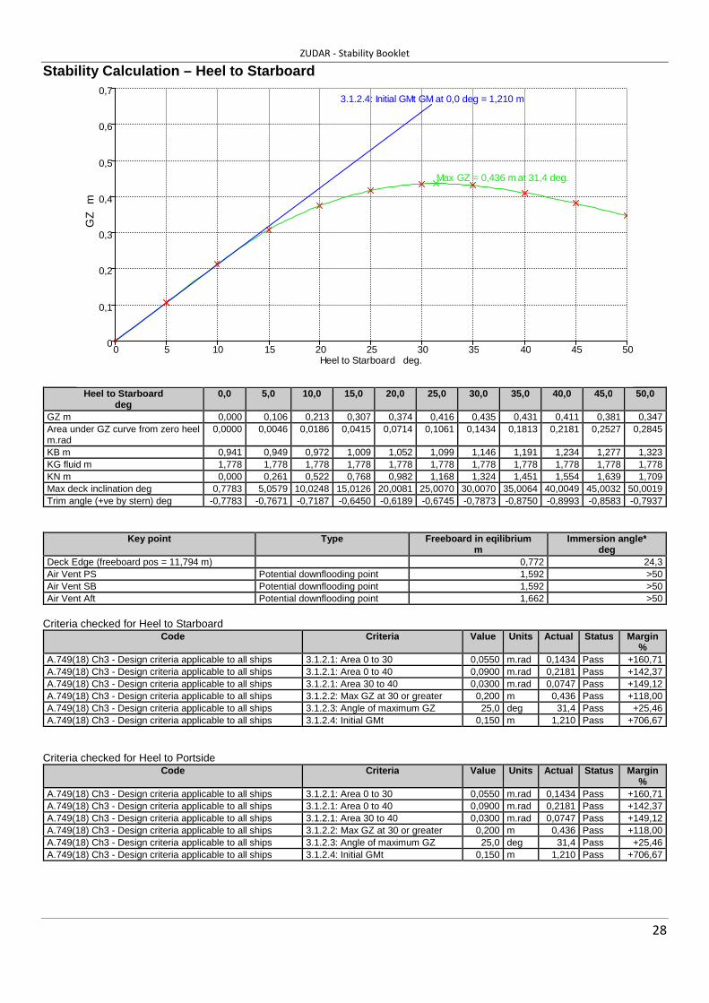
28
Stability Calculation – Heel to Starboard
Heel to Starboard
deg 0,0 5,0 10,0 15,0 20,0 25,0 30,0 35,0 40,0 45,0 50,0
GZ m 0,000 0,106 0,213 0,307 0,374 0,416 0,435 0,431 0,411 0,381 0,347 Area under GZ curve from zero heel m.rad
0,0000 0,0046 0,0186 0,0415 0,0714 0,1061 0,1434 0,1813 0,2181 0,2527 0,2845
KB m 0,941 0,949 0,972 1,009 1,052 1,099 1,146 1,191 1,234 1,277 1,323 KG fluid m 1,778 1,778 1,778 1,778 1,778 1,778 1,778 1,778 1,778 1,778 1,778 KN m 0,000 0,261 0,522 0,768 0,982 1,168 1,324 1,451 1,554 1,639 1,709 Max deck inclination deg 0,7783 5,0579 10,0248 15,0126 20,0081 25,0070 30,0070 35,0064 40,0049 45,0032 50,0019 Trim angle (+ve by stern) deg -0,7783 -0,7671 -0,7187 -0,6450 -0,6189 -0,6745 -0,7873 -0,8750 -0,8993 -0,8583 -0,7937
Key point Type Freeboard in eqilibrium m
Immersion angle * deg
Deck Edge (freeboard pos = 11,794 m) 0,772 24,3 Air Vent PS Potential downflooding point 1,592 >50 Air Vent SB Potential downflooding point 1,592 >50 Air Vent Aft Potential downflooding point 1,662 >50
Criteria checked for Heel to Starboard
Code Criteria Value Units Actual Status Margin %
A.749(18) Ch3 - Design criteria applicable to all ships 3.1.2.1: Area 0 to 30 0,0550 m.rad 0,1434 Pass +160,71 A.749(18) Ch3 - Design criteria applicable to all ships 3.1.2.1: Area 0 to 40 0,0900 m.rad 0,2181 Pass +142,37 A.749(18) Ch3 - Design criteria applicable to all ships 3.1.2.1: Area 30 to 40 0,0300 m.rad 0,0747 Pass +149,12 A.749(18) Ch3 - Design criteria applicable to all ships 3.1.2.2: Max GZ at 30 or greater 0,200 m 0,436 Pass +118,00 A.749(18) Ch3 - Design criteria applicable to all ships 3.1.2.3: Angle of maximum GZ 25,0 deg 31,4 Pass +25,46 A.749(18) Ch3 - Design criteria applicable to all ships 3.1.2.4: Initial GMt 0,150 m 1,210 Pass +706,67
Criteria checked for Heel to Portside
Code Criteria Value Units Actual Status Margin %
A.749(18) Ch3 - Design criteria applicable to all ships 3.1.2.1: Area 0 to 30 0,0550 m.rad 0,1434 Pass +160,71 A.749(18) Ch3 - Design criteria applicable to all ships 3.1.2.1: Area 0 to 40 0,0900 m.rad 0,2181 Pass +142,37 A.749(18) Ch3 - Design criteria applicable to all ships 3.1.2.1: Area 30 to 40 0,0300 m.rad 0,0747 Pass +149,12 A.749(18) Ch3 - Design criteria applicable to all ships 3.1.2.2: Max GZ at 30 or greater 0,200 m 0,436 Pass +118,00 A.749(18) Ch3 - Design criteria applicable to all ships 3.1.2.3: Angle of maximum GZ 25,0 deg 31,4 Pass +25,46 A.749(18) Ch3 - Design criteria applicable to all ships 3.1.2.4: Initial GMt 0,150 m 1,210 Pass +706,67
0
0,1
0,2
0,3
0,4
0,5
0,6
0,7
0 5 10 15 20 25 30 35 40 45 50
Max GZ = 0,436 m at 31,4 deg.
3.1.2.4: Initial GMt GM at 0,0 deg = 1,210 m
Heel to Starboard deg.
GZ
m

ZUDAR - Stability Booklet
29
6.2.3. Midway 50% of Consumables – sea going condition Free to Trim; Specific gravity = 1,025; (Density = 1,025 tonne/m^3)
Item Name Quantity Unit Mass tonne
Total Mass tonne
Unit Volume m^3
Total Volume m^3
Long. Arm m
Trans. Arm m
Vert. Arm m
Total FSM*
tonne.m Lightship 1 23,270 23,270 6,510 0,000 1,810 0,000 Crew 2 0,080 0,160 11,000 0,000 3,100 0,000 Pilots 5 0,080 0,400 7,600 0,000 1,700 0,000 Store 1 0,200 0,200 7,500 0,000 1,200 0,000 Fuel 50% 2,043 1,022 2,376 1,188 9,660 0,000 1,216 1,606 Fresh Water 50% 0,304 0,152 0,304 0,152 11,700 0,000 1,202 0,042 Total Loadcase 25,204 2,680 1,340 6,723 0,000 1,784 1,648 FS correction 0,065 VCG fluid 1,849
* Maximum FSM used for tanks
Equilibrium data
Draft Amidships m 1,212 KG fluid m 1,849 Displacement t 25,21 BMt m 2,117 Heel deg 0,0 BML m 32,776 Draft at FP m 1,283 GMt corrected m 1,194 Draft at AP m 1,141 GML m 31,853 Draft at LCF m 1,204 KMt m 3,043 Trim (+ve by stern) m -0,142 KML m 33,701 WL Length m 15,639 Immersion (TPc) tonne/cm 0,513 Beam max extents on WL m 3,825 MTc tonne.m 0,518 LCB from zero pt. (+ve fwd) m 6,731 RM at 1deg = GMt.Disp.sin(1) tonne.m 0,525 LCF from zero pt. (+ve fwd) m 6,820 Max deck inclination deg 0,5263 KB m 0,926 Trim angle (+ve by stern) deg -0,5263

ZUDAR - Stability Booklet
30
Stability Calculation - Heel to Starboard
Heel to Starboard
deg 0,0 5,0 10,0 15,0 20,0 25,0 30,0 35,0 40,0 45,0 50,0
GZ m 0,000 0,105 0,209 0,297 0,357 0,393 0,408 0,400 0,375 0,339 0,299 Area under GZ curve from zero heel m.rad
0,0000 0,0046 0,0183 0,0405 0,0693 0,1022 0,1373 0,1727 0,2066 0,2378 0,2656
KB m 0,926 0,934 0,959 0,996 1,039 1,086 1,135 1,181 1,225 1,268 1,314 KG fluid m 1,849 1,849 1,849 1,849 1,849 1,849 1,849 1,849 1,849 1,849 1,849 KN m 0,000 0,266 0,530 0,776 0,990 1,174 1,333 1,460 1,563 1,647 1,715 Max deck inclination deg 0,5263 5,0259 10,0100 15,0043 20,0026 25,0025 30,0029 35,0028 40,0022 45,0013 50,0006 Trim angle (+ve by stern) deg -0,5263 -0,5124 -0,4567 -0,3779 -0,3479 -0,4007 -0,5020 -0,5795 -0,5970 -0,5475 -0,4561
Key point Type Freeboard in eqilibrium m
Immersion angle * deg
Deck Edge (freeboard pos = 11,794 m) 0,816 25,7 Air Vent PS Potential downflooding point 1,596 >50 Air Vent SB Potential downflooding point 1,596 >50 Air Vent Aft Potential downflooding point 1,656 >50
* Heel to Starboard Criteria checked for Heel to Starboard
Code Criteria Value Units Actual Status Margin %
A.749(18) Ch3 - Design criteria applicable to all ships 3.1.2.1: Area 0 to 30 0,0550 m.rad 0,1373 Pass +149,63 A.749(18) Ch3 - Design criteria applicable to all ships 3.1.2.1: Area 0 to 40 0,0900 m.rad 0,2066 Pass +129,55 A.749(18) Ch3 - Design criteria applicable to all ships 3.1.2.1: Area 30 to 40 0,0300 m.rad 0,0693 Pass +130,99 A.749(18) Ch3 - Design criteria applicable to all ships 3.1.2.2: Max GZ at 30 or greater 0,200 m 0,409 Pass +104,50 A.749(18) Ch3 - Design criteria applicable to all ships 3.1.2.3: Angle of maximum GZ 25,0 deg 30,5 Pass +21,82 A.749(18) Ch3 - Design criteria applicable to all ships 3.1.2.4: Initial GMt 0,150 m 1,194 Pass +696,00
Criteria checked for Heel to Portside
Code Criteria Value Units Actual Status Margin %
A.749(18) Ch3 - Design criteria applicable to all ships 3.1.2.1: Area 0 to 30 0,0550 m.rad 0,1373 Pass +149,63 A.749(18) Ch3 - Design criteria applicable to all ships 3.1.2.1: Area 0 to 40 0,0900 m.rad 0,2066 Pass +129,55 A.749(18) Ch3 - Design criteria applicable to all ships 3.1.2.1: Area 30 to 40 0,0300 m.rad 0,0693 Pass +130,99 A.749(18) Ch3 - Design criteria applicable to all ships 3.1.2.2: Max GZ at 30 or greater 0,200 m 0,409 Pass +104,50 A.749(18) Ch3 - Design criteria applicable to all ships 3.1.2.3: Angle of maximum GZ 25,0 deg 30,5 Pass +21,82 A.749(18) Ch3 - Design criteria applicable to all ships 3.1.2.4: Initial GMt 0,150 m 1,194 Pass +696,00
0
0,1
0,2
0,3
0,4
0,5
0,6
0,7
0 5 10 15 20 25 30 35 40 45 50
Max GZ = 0,409 m at 30,5 deg.
3.1.2.4: Initial GMt GM at 0,0 deg = 1,194 m
Heel to Starboard deg.
GZ
m

ZUDAR - Stability Booklet
31
6.2.4. Arrival 10% of Consumables – sea going condition Free to Trim; Specific gravity = 1,025; (Density = 1,025 tonne/m^3)
Item Name Quantity Unit Mass tonne
Total Mass tonne
Unit Volume m^3
Total Volume m^3
Long. Arm m
Trans. Arm m
Vert. Arm m
Total FSM*
tonne.m Lightship 1 23,270 23,270 6,510 0,000 1,810 0,000 Crew 2 0,080 0,160 11,000 0,000 3,100 0,000 Pilots 5 0,080 0,400 7,600 0,000 1,700 0,000 Store 1 0,200 0,200 7,500 0,000 1,200 0,000 Fuel 10% 2,043 0,204 2,376 0,238 9,660 0,000 0,992 1,606 Fresh Water 10% 0,304 0,030 0,304 0,030 11,700 0,000 1,063 0,042 Total Loadcase 24,265 2,680 0,268 6,599 0,000 1,804 1,648 FS correction 0,068 VCG fluid 1,872
* Maximum FSM used for tanks
Equilibrium data
Draft Amidships m 1,190 KG fluid m 1,872 Displacement t 24,26 BMt m 2,176 Heel deg 0,0 BML m 33,256 Draft at FP m 1,233 GMt corrected m 1,219 Draft at AP m 1,148 GML m 32,300 Draft at LCF m 1,185 KMt m 3,091 Trim (+ve by stern) m -0,085 KML m 34,171 WL Length m 15,584 Immersion (TPc) tonne/cm 0,508 Beam max extents on WL m 3,823 MTc tonne.m 0,506 LCB from zero pt. (+ve fwd) m 6,605 RM at 1deg = GMt.Disp.sin(1) tonne.m 0,516 LCF from zero pt. (+ve fwd) m 6,764 Max deck inclination deg 0,3153 KB m 0,915 Trim angle (+ve by stern) deg -0,3153

ZUDAR - Stability Booklet
32
Stability Calculation – Heel to Starboard
Heel to Starboard
deg 0,0 5,0 10,0 15,0 20,0 25,0 30,0 35,0 40,0 45,0 50,0
GZ m 0,000 0,107 0,211 0,298 0,356 0,389 0,404 0,395 0,368 0,330 0,287 Area under GZ curve from zero heel m.rad
0,0000 0,0046 0,0186 0,0410 0,0698 0,1024 0,1372 0,1722 0,2056 0,2362 0,2631
KB m 0,915 0,923 0,948 0,985 1,029 1,076 1,126 1,174 1,218 1,262 1,308 KG fluid m 1,872 1,872 1,872 1,872 1,872 1,872 1,872 1,872 1,872 1,872 1,872 KN m 0,000 0,270 0,536 0,783 0,997 1,180 1,340 1,469 1,572 1,654 1,721 Max deck inclination deg 0,3153 5,0088 10,0027 15,0007 20,0003 25,0004 30,0008 35,0009 40,0007 45,0004 50,0001 Trim angle (+ve by stern) deg -0,3153 -0,2976 -0,2363 -0,1529 -0,1187 -0,1684 -0,2615 -0,3284 -0,3376 -0,2846 -0,1658
Key point Type Freeboard in eqilibrium m
Immersion angle * deg
Deck Edge (freeboard pos = 11,794 m) 0,853 26,7 Air Vent PS Potential downflooding point 1,598 >50 Air Vent SB Potential downflooding point 1,598 >50 Air Vent Aft Potential downflooding point 1,651 >50
* Heel to Starboard Criteria checked for Heel to Starboard
Code Criteria Value Units Actual Status Margin %
A.749(18) Ch3 - Design criteria applicable to all ships 3.1.2.1: Area 0 to 30 0,0550 m.rad 0,1372 Pass +149,43 A.749(18) Ch3 - Design criteria applicable to all ships 3.1.2.1: Area 0 to 40 0,0900 m.rad 0,2056 Pass +128,47 A.749(18) Ch3 - Design criteria applicable to all ships 3.1.2.1: Area 30 to 40 0,0300 m.rad 0,0684 Pass +128,11 A.749(18) Ch3 - Design criteria applicable to all ships 3.1.2.2: Max GZ at 30 or greater 0,200 m 0,404 Pass +102,00 A.749(18) Ch3 - Design criteria applicable to all ships 3.1.2.3: Angle of maximum GZ 25,0 deg 30,5 Pass +21,82 A.749(18) Ch3 - Design criteria applicable to all ships 3.1.2.4: Initial GMt 0,150 m 1,219 Pass +712,67
Criteria checked for Heel to Portside
Code Criteria Value Units Actual Status Margin %
A.749(18) Ch3 - Design criteria applicable to all ships 3.1.2.1: Area 0 to 30 0,0550 m.rad 0,1372 Pass +149,43 A.749(18) Ch3 - Design criteria applicable to all ships 3.1.2.1: Area 0 to 40 0,0900 m.rad 0,2056 Pass +128,47 A.749(18) Ch3 - Design criteria applicable to all ships 3.1.2.1: Area 30 to 40 0,0300 m.rad 0,0684 Pass +128,11 A.749(18) Ch3 - Design criteria applicable to all ships 3.1.2.2: Max GZ at 30 or greater 0,200 m 0,404 Pass +102,00 A.749(18) Ch3 - Design criteria applicable to all ships 3.1.2.3: Angle of maximum GZ 25,0 deg 30,5 Pass +21,82 A.749(18) Ch3 - Design criteria applicable to all ships 3.1.2.4: Initial GMt 0,150 m 1,219 Pass +712,67
0
0,1
0,2
0,3
0,4
0,5
0,6
0,7
0 5 10 15 20 25 30 35 40 45 50
Max GZ = 0,404 m at 30,5 deg.
3.1.2.4: Initial GMt GM at 0,0 deg = 1,219 m
Heel to Starboard deg.
GZ
m

ZUDAR - Stability Booklet
33
7. HYDROSTATICS DATA
7.2. HYDROSTATICS VALUES
7.2.1. HYDROSTATICS – TRIM -0,25M (BY BOW)
Damage Case - Intact
Fixed Trim = -0,25 m (+ve by stern)
Specific gravity = 1,025; (Density = 1,025 tonne/m^3)
Draft Amidships
m
Displacement
t
LCB
from zero pt. (+ve fwd) m
VCB
m
LCF
from zero pt. (+ve fwd) m
KMt
m
KML
m
Immersion (TPc)
tonne/cm
MTc
tonne.m
RM at 1deg = GMt.Disp.sin(1)
tonne.m
1,100 19,19 7,002 0,862 6,747 3,537 41,729 0,501 0,504 0,837
1,110 19,68 6,999 0,867 6,762 3,488 41,023 0,502 0,508 0,842
1,120 20,19 6,993 0,873 6,774 3,439 40,287 0,504 0,511 0,846
1,130 20,69 6,988 0,879 6,787 3,392 39,585 0,505 0,515 0,850
1,140 21,20 6,983 0,885 6,799 3,348 38,913 0,507 0,518 0,855
1,150 21,70 6,979 0,890 6,812 3,305 38,275 0,508 0,521 0,859
1,160 22,21 6,976 0,896 6,824 3,264 37,663 0,509 0,525 0,863
1,170 22,72 6,972 0,902 6,836 3,225 37,076 0,511 0,528 0,868
1,180 23,23 6,969 0,908 6,847 3,188 36,510 0,512 0,532 0,872
1,190 23,74 6,967 0,913 6,859 3,153 35,963 0,513 0,535 0,877
1,200 24,26 6,965 0,919 6,868 3,118 35,402 0,514 0,538 0,881
1,210 24,77 6,963 0,925 6,878 3,086 34,896 0,516 0,541 0,886
1,220 25,29 6,961 0,930 6,889 3,055 34,407 0,517 0,545 0,890
1,230 25,81 6,960 0,936 6,898 3,025 33,908 0,518 0,547 0,895
1,240 26,33 6,959 0,941 6,908 2,996 33,446 0,519 0,550 0,900
1,250 26,84 6,958 0,947 6,917 2,969 32,978 0,520 0,553 0,905
1,260 27,37 6,957 0,953 6,926 2,942 32,531 0,521 0,556 0,910
1,270 27,89 6,957 0,958 6,934 2,917 32,095 0,522 0,559 0,915
1,280 28,41 6,956 0,964 6,943 2,894 31,678 0,524 0,562 0,921
1,290 28,93 6,956 0,969 6,950 2,871 31,267 0,525 0,564 0,926
1,300 29,46 6,956 0,975 6,958 2,849 30,859 0,526 0,567 0,931

ZUDAR - Stability Booklet
34
1,1
1,125
1,15
1,175
1,2
1,225
1,25
1,275
1,3
1,325
18 19 20 21 22 23 24 25 26 27 28 29 30
0 10 20 30 40 50 60 70 80 90 100 110 120
6,66 6,69 6,72 6,75 6,78 6,81 6,84 6,87 6,9 6,93 6,96 6,99
0,86 0,87 0,88 0,89 0,9 0,91 0,92 0,93 0,94 0,95 0,96 0,97 0,98
2,4 2,5 2,6 2,7 2,8 2,9 3 3,1 3,2 3,3 3,4 3,5
30 31 32 33 34 35 36 37 38 39 40 41 42
-2 -1,5 -1 -0,5 0 0,5 1 1,5 2 2,5 3 3,5 4
-2 -1,5 -1 -0,5 0 0,5 1 1,5 2 2,5 3 3,5 4
DisplacementMax sect. areaSect. area amidships
Wetted AreaWaterpl. Area
LCBLCFKB
KMtKML
Immersion (TPc)MTc
Displacement t
Dra
ft
m
Area m^2
Long. centre from zero pt. (+ve fw d) m
KB m
KM trans. m
KM long. m
Immersion tonne/cm
Moment to trim tonne.m
1,1
1,125
1,15
1,175
1,2
1,225
1,25
1,275
1,3
1,325
0,3 0,35 0,4 0,45 0,5 0,55 0,6 0,65 0,7 0,75 0,8 0,85
Prismatic coeff. (Cp)
Block coeff. (Cb)
Max Sect. area coeff. (Cm)
Waterpl. area coeff. (Cw p)
Coeff icient
Dra
ft
m

ZUDAR - Stability Booklet
35
7.2.2. HYDROSTATICS – TRIM -0,2M (BY BOW)
Damage Case - Intact
Fixed Trim = -0,2 m (+ve by stern)
Specific gravity = 1,025; (Density = 1,025 tonne/m^3)
Draft Amidships
m
Displacement
t
LCB
from zero pt. (+ve fwd) m
VCB
m
LCF
from zero pt. (+ve fwd) m
KMt
m
KML
m
Immersion (TPc)
tonne/cm
MTc
tonne.m
RM at 1deg = GMt.Disp.sin(1)
tonne.m
1,100 19,34 6,873 0,862 6,717 3,508 41,027 0,499 0,489 0,572
1,110 19,84 6,869 0,868 6,731 3,458 40,287 0,501 0,493 0,569
1,120 20,35 6,866 0,873 6,744 3,411 39,579 0,502 0,496 0,567
1,130 20,85 6,863 0,879 6,756 3,366 38,904 0,503 0,499 0,565
1,140 21,35 6,861 0,885 6,769 3,323 38,258 0,505 0,502 0,562
1,150 21,86 6,859 0,891 6,781 3,282 37,640 0,506 0,505 0,560
1,160 22,37 6,857 0,896 6,794 3,242 37,048 0,508 0,508 0,557
1,170 22,87 6,856 0,902 6,806 3,205 36,481 0,509 0,512 0,555
1,180 23,38 6,855 0,908 6,818 3,169 35,939 0,510 0,515 0,553
1,190 23,89 6,854 0,913 6,830 3,134 35,417 0,512 0,518 0,550
1,200 24,41 6,854 0,919 6,841 3,101 34,909 0,513 0,521 0,548
1,210 24,92 6,854 0,925 6,850 3,069 34,392 0,514 0,524 0,546
1,220 25,43 6,854 0,930 6,862 3,039 33,916 0,515 0,527 0,544
1,230 25,95 6,854 0,936 6,873 3,010 33,460 0,517 0,530 0,541
1,240 26,47 6,855 0,942 6,882 2,982 32,992 0,518 0,532 0,539
1,250 26,99 6,855 0,947 6,892 2,955 32,568 0,519 0,535 0,537
1,260 27,51 6,856 0,953 6,901 2,929 32,130 0,520 0,538 0,535
1,270 28,03 6,857 0,958 6,911 2,905 31,728 0,521 0,541 0,533
1,280 28,55 6,858 0,964 6,919 2,881 31,315 0,522 0,543 0,532
1,290 29,07 6,859 0,970 6,927 2,859 30,915 0,523 0,546 0,530
1,300 29,60 6,860 0,975 6,935 2,837 30,535 0,525 0,548 0,528

ZUDAR - Stability Booklet
36
1,1
1,125
1,15
1,175
1,2
1,225
1,25
1,275
1,3
1,325
15 16 17 18 19 20 21 22 23 24 25 26 27 28 29 30
0 5 10 15 20 25 30 35 40 45 50 55 60 65 70 75
6,575 6,6 6,625 6,65 6,675 6,7 6,725 6,75 6,775 6,8 6,825 6,85 6,875 6,9 6,925 6,95
0,83 0,84 0,85 0,86 0,87 0,88 0,89 0,9 0,91 0,92 0,93 0,94 0,95 0,96 0,97 0,98
2,8 2,85 2,9 2,95 3 3,05 3,1 3,15 3,2 3,25 3,3 3,35 3,4 3,45 3,5 3,55
27 28 29 30 31 32 33 34 35 36 37 38 39 40 41 42
-2,5 -2 -1,5 -1 -0,5 0 0,5 1 1,5 2 2,5 3 3,5 4 4,5 5
-2,5 -2 -1,5 -1 -0,5 0 0,5 1 1,5 2 2,5 3 3,5 4 4,5 5
DisplacementMax sect. areaSect. area amidships
Wetted AreaWaterpl. Area
LCBLCF
KBKMt
KMLImmersion (TPc)
MTc
Displacement t
Dra
ft
m
Area m^2
Long. centre from zero pt. (+ve fw d) m
KB m
KM trans. m
KM long. m
Immersion tonne/cm
Moment to trim tonne.m
1,1
1,125
1,15
1,175
1,2
1,225
1,25
1,275
1,3
1,325
0,3 0,35 0,4 0,45 0,5 0,55 0,6 0,65 0,7 0,75 0,8 0,85
Prismatic coeff. (Cp)
Block coeff. (Cb)
Max Sect. area coeff. (Cm)
Waterpl. area coeff. (Cw p)
Coeff icient
Dra
ft
m

ZUDAR - Stability Booklet
37
7.2.3. HYDROSTATICS - TRIM -0,15M (BY BOW) Damage Case - Intact
Fixed Trim = -0,15 m (+ve by stern)
Specific gravity = 1,025; (Density = 1,025 tonne/m^3)
Draft Amidships
m
Displacement
t
LCB
from zero pt. (+ve fwd) m
VCB
m
LCF
from zero pt. (+ve fwd) m
KMt
m
KML
m
Immersion (TPc)
tonne/cm
MTc
tonne.m
RM at 1deg = GMt.Disp.sin(1)
tonne.m
1,100 19,51 6,744 0,862 6,686 3,476 40,271 0,497 0,484 0,567
1,110 20,01 6,742 0,868 6,701 3,430 39,590 0,499 0,488 0,565
1,120 20,51 6,742 0,874 6,714 3,384 38,910 0,500 0,491 0,563
1,130 21,01 6,741 0,880 6,727 3,341 38,261 0,502 0,494 0,561
1,140 21,51 6,741 0,885 6,740 3,299 37,639 0,503 0,497 0,558
1,150 22,02 6,741 0,891 6,753 3,259 37,043 0,505 0,501 0,556
1,160 22,52 6,741 0,897 6,766 3,221 36,473 0,506 0,504 0,554
1,170 23,03 6,742 0,902 6,778 3,185 35,926 0,508 0,507 0,552
1,180 23,54 6,743 0,908 6,788 3,149 35,366 0,509 0,510 0,549
1,190 24,05 6,744 0,914 6,800 3,115 34,857 0,510 0,513 0,547
1,200 24,56 6,745 0,919 6,812 3,083 34,374 0,511 0,516 0,545
1,210 25,07 6,747 0,925 6,824 3,053 33,907 0,513 0,519 0,543
1,220 25,58 6,748 0,931 6,834 3,023 33,422 0,514 0,522 0,541
1,230 26,10 6,750 0,936 6,845 2,995 32,986 0,515 0,525 0,539
1,240 26,61 6,752 0,942 6,856 2,967 32,562 0,516 0,528 0,537
1,250 27,13 6,754 0,948 6,865 2,941 32,123 0,518 0,531 0,535
1,260 27,65 6,756 0,953 6,875 2,916 31,728 0,519 0,534 0,533
1,270 28,17 6,759 0,959 6,885 2,892 31,324 0,520 0,536 0,531
1,280 28,69 6,761 0,964 6,895 2,869 30,946 0,521 0,539 0,529
1,290 29,21 6,764 0,970 6,903 2,847 30,561 0,522 0,542 0,528
1,300 29,73 6,766 0,975 6,912 2,826 30,202 0,523 0,545 0,526

ZUDAR - Stability Booklet
38
1,0751,1
1,1251,15
1,1751,2
1,2251,25
1,2751,3
1,325
16 17 18 19 20 21 22 23 24 25 26 27 28 29 30
0 5 10 15 20 25 30 35 40 45 50 55 60 65 70
6,575 6,6 6,625 6,65 6,675 6,7 6,725 6,75 6,775 6,8 6,825 6,85 6,875 6,9 6,925
0,84 0,85 0,86 0,87 0,88 0,89 0,9 0,91 0,92 0,93 0,94 0,95 0,96 0,97 0,98
2,8 2,85 2,9 2,95 3 3,05 3,1 3,15 3,2 3,25 3,3 3,35 3,4 3,45
27 28 29 30 31 32 33 34 35 36 37 38 39 40 41
-2,5 -2 -1,5 -1 -0,5 0 0,5 1 1,5 2 2,5 3 3,5 4 4,5
-2,5 -2 -1,5 -1 -0,5 0 0,5 1 1,5 2 2,5 3 3,5 4 4,5
DisplacementMax sect. areaSect. area amidships
Wetted AreaWaterpl. Area
LCBLCF
KBKMt
KMLImmersion (TPc)
MTc
Displacement t
Dra
ft
m
Area m^2
Long. centre from zero pt. (+ve fw d) m
KB m
KM trans. m
KM long. m
Immersion tonne/cm
Moment to trim tonne.m
1,075
1,1
1,125
1,15
1,175
1,2
1,225
1,25
1,275
1,3
1,325
0,3 0,35 0,4 0,45 0,5 0,55 0,6 0,65 0,7 0,75 0,8 0,85
Prismatic coeff. (Cp)
Block coeff. (Cb)
Max Sect. area coeff. (Cm)
Waterpl. area coeff. (Cw p)
Coeff icient
Dra
ft
m

ZUDAR - Stability Booklet
39
7.2.4. HYDROSTATICS - TRIM -0,1M (BY BOW)
Damage Case - Intact
Fixed Trim = -0,1 m (+ve by stern)
Specific gravity = 1,025; (Density = 1,025 tonne/m^3)
Draft Amidships
m
Displacement
t
LCB
from zero pt. (+ve fwd) m
VCB
m
LCF
from zero pt. (+ve fwd) m
KMt
m
KML
m
Immersion (TPc)
tonne/cm
MTc
tonne.m
RM at 1deg = GMt.Disp.sin(1)
tonne.m
1,100 19,69 6,618 0,863 6,655 3,445 39,548 0,496 0,479 0,562
1,110 20,18 6,619 0,869 6,669 3,400 38,867 0,497 0,483 0,560
1,120 20,68 6,620 0,875 6,684 3,357 38,236 0,499 0,486 0,558
1,130 21,18 6,622 0,880 6,698 3,315 37,619 0,500 0,489 0,556
1,140 21,68 6,624 0,886 6,711 3,275 37,019 0,502 0,492 0,554
1,150 22,18 6,626 0,892 6,724 3,237 36,447 0,503 0,496 0,552
1,160 22,69 6,628 0,898 6,735 3,199 35,865 0,504 0,498 0,550
1,170 23,19 6,631 0,903 6,747 3,163 35,333 0,506 0,502 0,548
1,180 23,70 6,633 0,909 6,760 3,130 34,826 0,507 0,505 0,546
1,190 24,21 6,636 0,915 6,772 3,097 34,339 0,509 0,508 0,544
1,200 24,72 6,639 0,920 6,785 3,066 33,871 0,510 0,511 0,542
1,210 25,23 6,642 0,926 6,794 3,036 33,387 0,511 0,514 0,539
1,220 25,74 6,645 0,932 6,806 3,007 32,952 0,513 0,517 0,537
1,230 26,25 6,648 0,937 6,818 2,980 32,535 0,514 0,520 0,536
1,240 26,77 6,652 0,943 6,828 2,953 32,097 0,515 0,523 0,534
1,250 27,28 6,655 0,948 6,839 2,928 31,704 0,516 0,526 0,532
1,260 27,80 6,659 0,954 6,848 2,903 31,293 0,517 0,529 0,530
1,270 28,32 6,662 0,960 6,859 2,880 30,923 0,519 0,532 0,528
1,280 28,84 6,666 0,965 6,869 2,857 30,565 0,520 0,535 0,527
1,290 29,36 6,670 0,971 6,878 2,836 30,192 0,521 0,538 0,525
1,300 29,88 6,673 0,976 6,887 2,815 29,830 0,522 0,540 0,523

ZUDAR - Stability Booklet
40
1,0751,1
1,1251,15
1,1751,2
1,2251,25
1,2751,3
1,325
16 17 18 19 20 21 22 23 24 25 26 27 28 29 30
0 5 10 15 20 25 30 35 40 45 50 55 60 65 70
6,48 6,51 6,54 6,57 6,6 6,63 6,66 6,69 6,72 6,75 6,78 6,81 6,84 6,87 6,9
0,84 0,85 0,86 0,87 0,88 0,89 0,9 0,91 0,92 0,93 0,94 0,95 0,96 0,97 0,98
2,75 2,8 2,85 2,9 2,95 3 3,05 3,1 3,15 3,2 3,25 3,3 3,35 3,4
26 27 28 29 30 31 32 33 34 35 36 37 38 39 40
-2,5 -2 -1,5 -1 -0,5 0 0,5 1 1,5 2 2,5 3 3,5 4 4,5
-2,5 -2 -1,5 -1 -0,5 0 0,5 1 1,5 2 2,5 3 3,5 4 4,5
DisplacementMax sect. areaSect. area amidships
Wetted AreaWaterpl. Area
LCBLCF
KBKMt
KMLImmersion (TPc)
MTc
Displacement t
Dra
ft
m
Area m^2
Long. centre from zero pt. (+ve fw d) m
KB m
KM trans. m
KM long. m
Immersion tonne/cm
Moment to trim tonne.m
1,075
1,1
1,125
1,15
1,175
1,2
1,225
1,25
1,275
1,3
1,325
0,3 0,35 0,4 0,45 0,5 0,55 0,6 0,65 0,7 0,75 0,8 0,85
Prismatic coeff. (Cp)
Block coeff. (Cb)
Max Sect. area coeff. (Cm)
Waterpl. area coeff. (Cw p)
Coeff icient
Dra
ft
m

ZUDAR - Stability Booklet
41
7.2.5. HYDROSTATICS - TRIM -0,05M (BY BOW)
Damage Case - Intact
Fixed Trim = -0,05 m (+ve by stern)
Specific gravity = 1,025; (Density = 1,025 tonne/m^3)
Draft Amidships
m
Displacement
t
LCB
from zero pt. (+ve fwd) m
VCB
m
LCF
from zero pt. (+ve fwd) m
KMt
m
KML
m
Immersion (TPc)
tonne/cm
MTc
tonne.m
RM at 1deg = GMt.Disp.sin(1)
tonne.m
1,100 19,86 6,495 0,865 6,625 3,415 38,827 0,494 0,474 0,556
1,110 20,36 6,498 0,870 6,639 3,371 38,174 0,495 0,478 0,554
1,120 20,85 6,502 0,876 6,654 3,330 37,568 0,497 0,481 0,553
1,130 21,35 6,505 0,882 6,668 3,290 36,977 0,499 0,484 0,551
1,140 21,85 6,509 0,888 6,682 3,251 36,403 0,500 0,488 0,550
1,150 22,35 6,513 0,893 6,695 3,214 35,844 0,502 0,491 0,548
1,160 22,85 6,517 0,899 6,706 3,177 35,290 0,503 0,494 0,545
1,170 23,36 6,522 0,905 6,719 3,143 34,779 0,504 0,497 0,543
1,180 23,86 6,526 0,910 6,732 3,111 34,290 0,506 0,500 0,542
1,190 24,37 6,530 0,916 6,744 3,079 33,820 0,507 0,503 0,540
1,200 24,88 6,535 0,922 6,754 3,048 33,335 0,508 0,506 0,538
1,210 25,39 6,539 0,927 6,767 3,019 32,900 0,510 0,509 0,536
1,220 25,90 6,544 0,933 6,779 2,992 32,481 0,511 0,512 0,534
1,230 26,41 6,548 0,938 6,789 2,965 32,044 0,512 0,515 0,532
1,240 26,92 6,553 0,944 6,800 2,939 31,652 0,514 0,518 0,530
1,250 27,44 6,558 0,950 6,812 2,914 31,277 0,515 0,522 0,529
1,260 27,95 6,563 0,955 6,822 2,890 30,881 0,516 0,524 0,527
1,270 28,47 6,568 0,961 6,833 2,868 30,526 0,517 0,527 0,525
1,280 28,99 6,572 0,966 6,842 2,845 30,152 0,519 0,530 0,524
1,290 29,50 6,577 0,972 6,853 2,824 29,817 0,520 0,533 0,522
1,300 30,03 6,582 0,977 6,862 2,804 29,465 0,521 0,536 0,521

ZUDAR - Stability Booklet
42
1,1
1,125
1,15
1,175
1,2
1,225
1,25
1,275
1,3
1,325
17 18 19 20 21 22 23 24 25 26 27 28 29 30 31
0 5 10 15 20 25 30 35 40 45 50 55 60 65 70
6,32 6,36 6,4 6,44 6,48 6,52 6,56 6,6 6,64 6,68 6,72 6,76 6,8 6,84
0,84 0,85 0,86 0,87 0,88 0,89 0,9 0,91 0,92 0,93 0,94 0,95 0,96 0,97 0,98
2,75 2,8 2,85 2,9 2,95 3 3,05 3,1 3,15 3,2 3,25 3,3 3,35 3,4
25 26 27 28 29 30 31 32 33 34 35 36 37 38 39
-2,5 -2 -1,5 -1 -0,5 0 0,5 1 1,5 2 2,5 3 3,5 4 4,5
-2,5 -2 -1,5 -1 -0,5 0 0,5 1 1,5 2 2,5 3 3,5 4 4,5
DisplacementMax sect. areaSect. area amidships
Wetted AreaWaterpl. Area
LCBLCF
KBKMt
KMLImmersion (TPc)
MTc
Displacement t
Dra
ft
m
Area m^2
Long. centre from zero pt. (+ve fw d) m
KB m
KM trans. m
KM long. m
Immersion tonne/cm
Moment to trim tonne.m
1,1
1,125
1,15
1,175
1,2
1,225
1,25
1,275
1,3
1,325
0,3 0,35 0,4 0,45 0,5 0,55 0,6 0,65 0,7 0,75 0,8 0,85
Prismatic coeff. (Cp)
Block coeff. (Cb)
Max Sect. area coeff. (Cm)
Waterpl. area coeff. (Cw p)
Coeff icient
Dra
ft
m

ZUDAR - Stability Booklet
43
7.2.6. HYDROSTATICS - TRIM 0M Damage Case - Intact
Fixed Trim = 0 m (+ve by stern)
Specific gravity = 1,025; (Density = 1,025 tonne/m^3)
Draft Amidships
m
Displacement
t
LCB
from zero pt. (+ve fwd) m
VCB
m
LCF
from zero pt. (+ve fwd) m
KMt
m
KML
m
Immersion (TPc)
tonne/cm
MTc
tonne.m
RM at 1deg = GMt.Disp.sin(1)
tonne.m
1,100 20,04 6,375 0,867 6,595 3,386 38,130 0,492 0,470 0,551
1,110 20,54 6,380 0,872 6,610 3,343 37,506 0,494 0,473 0,550
1,120 21,03 6,386 0,878 6,624 3,303 36,908 0,495 0,476 0,548
1,130 21,53 6,392 0,884 6,638 3,264 36,334 0,497 0,480 0,546
1,140 22,03 6,397 0,889 6,652 3,227 35,784 0,498 0,483 0,545
1,150 22,52 6,403 0,895 6,665 3,191 35,255 0,500 0,486 0,543
1,160 23,03 6,409 0,901 6,677 3,156 34,728 0,501 0,489 0,541
1,170 23,53 6,415 0,906 6,690 3,123 34,228 0,503 0,492 0,539
1,180 24,03 6,421 0,912 6,703 3,091 33,756 0,504 0,495 0,537
1,190 24,54 6,427 0,918 6,716 3,061 33,300 0,506 0,498 0,536
1,200 25,04 6,433 0,923 6,726 3,031 32,834 0,507 0,501 0,534
1,210 25,55 6,439 0,929 6,738 3,003 32,412 0,508 0,504 0,532
1,220 26,06 6,445 0,934 6,751 2,976 32,007 0,510 0,508 0,530
1,230 26,57 6,451 0,940 6,761 2,950 31,585 0,511 0,510 0,528
1,240 27,08 6,457 0,946 6,773 2,925 31,208 0,512 0,514 0,527
1,250 27,59 6,463 0,951 6,783 2,900 30,813 0,513 0,516 0,525
1,260 28,11 6,469 0,957 6,795 2,877 30,462 0,515 0,520 0,524
1,270 28,62 6,474 0,962 6,805 2,855 30,100 0,516 0,522 0,522
1,280 29,14 6,480 0,968 6,816 2,834 29,760 0,517 0,525 0,521
1,290 29,66 6,486 0,973 6,827 2,813 29,432 0,518 0,529 0,519
1,300 30,18 6,492 0,979 6,836 2,793 29,097 0,520 0,531 0,518

ZUDAR - Stability Booklet
44
1,1
1,125
1,15
1,175
1,2
1,225
1,25
1,275
1,3
1,325
17 18 19 20 21 22 23 24 25 26 27 28 29 30 31
0 5 10 15 20 25 30 35 40 45 50 55 60 65 70
6,15 6,2 6,25 6,3 6,35 6,4 6,45 6,5 6,55 6,6 6,65 6,7 6,75 6,8 6,85
0,84 0,85 0,86 0,87 0,88 0,89 0,9 0,91 0,92 0,93 0,94 0,95 0,96 0,97 0,98
2,7 2,75 2,8 2,85 2,9 2,95 3 3,05 3,1 3,15 3,2 3,25 3,3 3,35 3,4
25 26 27 28 29 30 31 32 33 34 35 36 37 38 39
-2,5 -2 -1,5 -1 -0,5 0 0,5 1 1,5 2 2,5 3 3,5 4 4,5
-2,5 -2 -1,5 -1 -0,5 0 0,5 1 1,5 2 2,5 3 3,5 4 4,5
DisplacementMax sect. areaSect. area amidships
Wetted AreaWaterpl. Area
LCBLCF
KBKMt
KMLImmersion (TPc)
MTc
Displacement t
Dra
ft
m
Area m^2
Long. centre from zero pt. (+ve fw d) m
KB m
KM trans. m
KM long. m
Immersion tonne/cm
Moment to trim tonne.m
1,1
1,125
1,15
1,175
1,2
1,225
1,25
1,275
1,3
1,325
0,3 0,35 0,4 0,45 0,5 0,55 0,6 0,65 0,7 0,75 0,8 0,85
Prismatic coeff. (Cp)
Block coeff. (Cb)
Max Sect. area coeff. (Cm)
Waterpl. area coeff. (Cw p)
Coeff icient
Dra
ft
m

ZUDAR - Stability Booklet
45
7.2.7. HYDROSTATICS - TRIM 0,05M (BY STERN) Damage Case - Intact
Fixed Trim = 0,05 m (+ve by stern)
Specific gravity = 1,025; (Density = 1,025 tonne/m^3)
Draft Amidships
m
Displacement
t
LCB
from zero pt. (+ve fwd) m
VCB
m
LCF
from zero pt. (+ve fwd) m
KMt
m
KML
m
Immersion (TPc)
tonne/cm
MTc
tonne.m
RM at 1deg = GMt.Disp.sin(1)
tonne.m
1,100 20,23 6,258 0,869 6,564 3,355 37,415 0,490 0,465 0,545
1,110 20,72 6,266 0,875 6,579 3,315 36,819 0,492 0,468 0,544
1,120 21,21 6,273 0,880 6,593 3,276 36,246 0,494 0,471 0,542
1,130 21,71 6,281 0,886 6,607 3,238 35,696 0,495 0,475 0,541
1,140 22,20 6,288 0,892 6,621 3,203 35,168 0,497 0,478 0,539
1,150 22,70 6,296 0,897 6,635 3,168 34,660 0,498 0,481 0,538
1,160 23,20 6,303 0,903 6,649 3,135 34,171 0,500 0,484 0,536
1,170 23,70 6,310 0,908 6,663 3,104 33,701 0,501 0,488 0,535
1,180 24,20 6,318 0,914 6,674 3,072 33,221 0,503 0,490 0,533
1,190 24,71 6,325 0,920 6,687 3,043 32,783 0,504 0,494 0,531
1,200 25,21 6,333 0,925 6,700 3,015 32,361 0,505 0,497 0,530
1,210 25,72 6,340 0,931 6,710 2,986 31,926 0,507 0,500 0,528
1,220 26,23 6,347 0,936 6,723 2,960 31,532 0,508 0,503 0,526
1,230 26,73 6,355 0,942 6,733 2,935 31,125 0,509 0,506 0,524
1,240 27,24 6,362 0,947 6,746 2,911 30,760 0,511 0,509 0,523
1,250 27,76 6,369 0,953 6,758 2,887 30,408 0,512 0,512 0,522
1,260 28,27 6,376 0,959 6,768 2,864 30,037 0,513 0,515 0,520
1,270 28,78 6,383 0,964 6,780 2,843 29,709 0,515 0,518 0,519
1,280 29,30 6,390 0,970 6,789 2,822 29,365 0,516 0,521 0,517
1,290 29,81 6,397 0,975 6,799 2,802 29,027 0,517 0,524 0,516
1,300 30,33 6,404 0,981 6,810 2,782 28,726 0,518 0,527 0,515

ZUDAR - Stability Booklet
46
1,1
1,125
1,15
1,175
1,2
1,225
1,25
1,275
1,3
1,325
17 18 19 20 21 22 23 24 25 26 27 28 29 30 31
0 5 10 15 20 25 30 35 40 45 50 55 60 65 70
6,15 6,2 6,25 6,3 6,35 6,4 6,45 6,5 6,55 6,6 6,65 6,7 6,75 6,8 6,85
0,85 0,86 0,87 0,88 0,89 0,9 0,91 0,92 0,93 0,94 0,95 0,96 0,97 0,98 0,99
2,7 2,75 2,8 2,85 2,9 2,95 3 3,05 3,1 3,15 3,2 3,25 3,3 3,35 3,4
24 25 26 27 28 29 30 31 32 33 34 35 36 37 38
-2,5 -2 -1,5 -1 -0,5 0 0,5 1 1,5 2 2,5 3 3,5 4 4,5
-2,5 -2 -1,5 -1 -0,5 0 0,5 1 1,5 2 2,5 3 3,5 4 4,5
DisplacementMax sect. areaSect. area amidships
Wetted AreaWaterpl. Area
LCBLCF
KBKMt
KMLImmersion (TPc)
MTc
Displacement t
Dra
ft
m
Area m^2
Long. centre from zero pt. (+ve fw d) m
KB m
KM trans. m
KM long. m
Immersion tonne/cm
Moment to trim tonne.m
1,1
1,125
1,15
1,175
1,2
1,225
1,25
1,275
1,3
1,325
0,3 0,35 0,4 0,45 0,5 0,55 0,6 0,65 0,7 0,75 0,8 0,85
Prismatic coeff. (Cp)
Block coeff. (Cb)
Max Sect. area coeff. (Cm)
Waterpl. area coeff. (Cw p)
Coeff icient
Dra
ft
m

ZUDAR - Stability Booklet
47
7.2.8. HYDROSTATICS - TRIM 0,1M (BY STERN) Damage Case - Intact
Fixed Trim = 0,1 m (+ve by stern)
Specific gravity = 1,025; (Density = 1,025 tonne/m^3)
Draft Amidships
m
Displacement
t
LCB
from zero pt. (+ve fwd) m
VCB
m
LCF
from zero pt. (+ve fwd) m
KMt
m
KML
m
Immersion (TPc)
tonne/cm
MTc
tonne.m
RM at 1deg = GMt.Disp.sin(1)
tonne.m
1,100 20,42 6,145 0,872 6,534 3,327 36,721 0,489 0,460 0,540
1,110 20,91 6,154 0,877 6,549 3,288 36,152 0,490 0,463 0,538
1,120 21,40 6,163 0,883 6,564 3,250 35,605 0,492 0,467 0,537
1,130 21,89 6,173 0,889 6,578 3,214 35,080 0,494 0,470 0,536
1,140 22,39 6,182 0,894 6,593 3,180 34,575 0,495 0,473 0,534
1,150 22,88 6,191 0,900 6,605 3,145 34,067 0,497 0,476 0,533
1,160 23,38 6,200 0,905 6,619 3,114 33,597 0,498 0,479 0,531
1,170 23,88 6,209 0,911 6,633 3,083 33,145 0,500 0,483 0,530
1,180 24,38 6,217 0,917 6,646 3,054 32,709 0,501 0,486 0,528
1,190 24,88 6,226 0,922 6,658 3,024 32,264 0,502 0,489 0,527
1,200 25,39 6,235 0,928 6,671 2,997 31,857 0,504 0,492 0,525
1,210 25,89 6,243 0,933 6,684 2,971 31,465 0,505 0,495 0,524
1,220 26,40 6,252 0,939 6,695 2,945 31,060 0,507 0,498 0,522
1,230 26,90 6,260 0,944 6,708 2,920 30,694 0,508 0,501 0,521
1,240 27,41 6,269 0,950 6,718 2,896 30,310 0,509 0,504 0,519
1,250 27,92 6,277 0,955 6,730 2,874 29,970 0,511 0,507 0,518
1,260 28,43 6,285 0,961 6,740 2,852 29,621 0,512 0,510 0,516
1,270 28,95 6,294 0,966 6,752 2,831 29,302 0,513 0,513 0,515
1,280 29,46 6,302 0,972 6,762 2,810 28,964 0,514 0,516 0,513
1,290 29,97 6,310 0,977 6,774 2,791 28,665 0,516 0,519 0,512
1,300 30,49 6,318 0,983 6,784 2,772 28,346 0,517 0,522 0,511

ZUDAR - Stability Booklet
48
1,0751,1
1,1251,15
1,1751,2
1,2251,25
1,2751,3
1,325
17 18 19 20 21 22 23 24 25 26 27 28 29 30 31
0 5 10 15 20 25 30 35 40 45 50 55 60 65 70
6,1 6,15 6,2 6,25 6,3 6,35 6,4 6,45 6,5 6,55 6,6 6,65 6,7 6,75 6,8
0,85 0,86 0,87 0,88 0,89 0,9 0,91 0,92 0,93 0,94 0,95 0,96 0,97 0,98 0,99
2,65 2,7 2,75 2,8 2,85 2,9 2,95 3 3,05 3,1 3,15 3,2 3,25 3,3 3,35
23 24 25 26 27 28 29 30 31 32 33 34 35 36 37
-2,5 -2 -1,5 -1 -0,5 0 0,5 1 1,5 2 2,5 3 3,5 4 4,5
-2,5 -2 -1,5 -1 -0,5 0 0,5 1 1,5 2 2,5 3 3,5 4 4,5
DisplacementMax sect. areaSect. area amidships
Wetted AreaWaterpl. Area
LCBLCF
KBKMt
KMLImmersion (TPc)
MTc
Displacement t
Dra
ft
m
Area m^2
Long. centre from zero pt. (+ve fw d) m
KB m
KM trans. m
KM long. m
Immersion tonne/cm
Moment to trim tonne.m
1,075
1,1
1,125
1,15
1,175
1,2
1,225
1,25
1,275
1,3
1,325
0,3 0,35 0,4 0,45 0,5 0,55 0,6 0,65 0,7 0,75 0,8 0,85
Prismatic coeff . (Cp)
Block coeff. (Cb)
Max Sect. area coeff. (Cm)
Waterpl. area coeff. (Cw p)
Coeff icient
Dra
ft
m

ZUDAR - Stability Booklet
49
7.2.9. HYDROSTATICS - TRIM 0,15M (BY STERN) Damage Case - Intact
Fixed Trim = 0,15 m (+ve by stern)
Specific gravity = 1,025; (Density = 1,025 tonne/m^3)
Draft Amidships
m
Displacement
t
LCB
from zero pt. (+ve fwd) m
VCB
m
LCF
from zero pt. (+ve fwd) m
KMt
m
KML
m
Immersion (TPc)
tonne/cm
MTc
tonne.m
RM at 1deg = GMt.Disp.sin(1)
tonne.m
1,100 20,61 6,034 0,875 6,503 3,299 36,030 0,487 0,455 0,534
1,110 21,10 6,045 0,880 6,518 3,261 35,488 0,489 0,458 0,533
1,120 21,59 6,056 0,886 6,534 3,225 34,964 0,490 0,462 0,532
1,130 22,08 6,067 0,892 6,549 3,191 34,463 0,492 0,465 0,530
1,140 22,57 6,078 0,897 6,562 3,156 33,961 0,493 0,468 0,529
1,150 23,07 6,088 0,903 6,576 3,124 33,494 0,495 0,472 0,527
1,160 23,56 6,099 0,908 6,591 3,093 33,045 0,497 0,475 0,526
1,170 24,06 6,109 0,914 6,605 3,064 32,612 0,498 0,478 0,525
1,180 24,56 6,119 0,919 6,617 3,034 32,171 0,499 0,481 0,523
1,190 25,06 6,129 0,925 6,631 3,007 31,767 0,501 0,484 0,522
1,200 25,56 6,139 0,930 6,644 2,981 31,377 0,502 0,488 0,521
1,210 26,07 6,149 0,936 6,655 2,954 30,975 0,504 0,490 0,519
1,220 26,57 6,159 0,941 6,669 2,930 30,610 0,505 0,494 0,518
1,230 27,08 6,168 0,947 6,678 2,906 30,246 0,507 0,497 0,516
1,240 27,58 6,178 0,952 6,691 2,883 29,904 0,508 0,500 0,515
1,250 28,09 6,187 0,958 6,702 2,860 29,545 0,509 0,503 0,513
1,260 28,60 6,196 0,963 6,715 2,839 29,225 0,511 0,506 0,512
1,270 29,11 6,206 0,969 6,725 2,818 28,886 0,512 0,509 0,511
1,280 29,63 6,215 0,974 6,737 2,799 28,586 0,513 0,512 0,510
1,290 30,14 6,224 0,980 6,748 2,779 28,267 0,514 0,514 0,508
1,300 30,65 6,232 0,985 6,756 2,761 27,976 0,516 0,517 0,507

ZUDAR - Stability Booklet
50
1,0751,1
1,1251,15
1,1751,2
1,2251,25
1,2751,3
1,325
17 18 19 20 21 22 23 24 25 26 27 28 29 30 31
0 5 10 15 20 25 30 35 40 45 50 55 60 65 70
5,4 5,5 5,6 5,7 5,8 5,9 6 6,1 6,2 6,3 6,4 6,5 6,6 6,7 6,8
0,85 0,86 0,87 0,88 0,89 0,9 0,91 0,92 0,93 0,94 0,95 0,96 0,97 0,98 0,99
2,6 2,65 2,7 2,75 2,8 2,85 2,9 2,95 3 3,05 3,1 3,15 3,2 3,25 3,3
23 24 25 26 27 28 29 30 31 32 33 34 35 36 37
-2,5 -2 -1,5 -1 -0,5 0 0,5 1 1,5 2 2,5 3 3,5 4 4,5
-2,5 -2 -1,5 -1 -0,5 0 0,5 1 1,5 2 2,5 3 3,5 4 4,5
DisplacementMax sect. areaSect. area amidships
Wetted AreaWaterpl. Area
LCBLCF
KBKMt
KMLImmersion (TPc)
MTc
Displacement t
Dra
ft
m
Area m^2
Long. centre from zero pt. (+ve fw d) m
KB m
KM trans. m
KM long. m
Immersion tonne/cm
Moment to trim tonne.m
1,075
1,1
1,125
1,15
1,175
1,2
1,225
1,25
1,275
1,3
1,325
0,3 0,35 0,4 0,45 0,5 0,55 0,6 0,65 0,7 0,75 0,8 0,85
Prismatic coeff. (Cp)
Block coeff. (Cb)
Max Sect. area coeff. (Cm)
Waterpl. area coeff. (Cw p)
Coefficient
Dra
ft
m

ZUDAR - Stability Booklet
51
7.2.10. HYDROSTATICS - TRIM 0,2M (BY STERN) Damage Case - Intact
Fixed Trim = 0,2 m (+ve by stern)
Specific gravity = 1,025; (Density = 1,025 tonne/m^3)
Draft Amidships
m
Displacement
t
LCB
from zero pt. (+ve fwd) m
VCB
m
LCF
from zero pt. (+ve fwd) m
KMt
m
KML
m
Immersion (TPc)
tonne/cm
MTc
tonne.m
RM at 1deg = GMt.Disp.sin(1)
tonne.m
1,100 20,81 5,927 0,878 6,472 3,271 35,339 0,485 0,450 0,528
1,110 21,30 5,940 0,884 6,488 3,235 34,822 0,487 0,454 0,527
1,120 21,79 5,952 0,889 6,504 3,200 34,325 0,489 0,457 0,526
1,130 22,27 5,964 0,895 6,519 3,167 33,846 0,490 0,460 0,525
1,140 22,77 5,976 0,901 6,532 3,133 33,365 0,492 0,463 0,523
1,150 23,26 5,988 0,906 6,547 3,103 32,920 0,493 0,467 0,522
1,160 23,75 6,000 0,912 6,562 3,073 32,490 0,495 0,470 0,521
1,170 24,25 6,012 0,917 6,575 3,043 32,055 0,496 0,473 0,519
1,180 24,75 6,023 0,923 6,589 3,016 31,654 0,498 0,476 0,518
1,190 25,24 6,034 0,928 6,603 2,990 31,267 0,499 0,480 0,517
1,200 25,74 6,045 0,933 6,615 2,963 30,869 0,501 0,483 0,515
1,210 26,25 6,056 0,939 6,627 2,939 30,526 0,502 0,486 0,515
1,220 26,75 6,067 0,944 6,639 2,914 30,150 0,504 0,489 0,513
1,230 27,25 6,078 0,950 6,652 2,891 29,808 0,505 0,492 0,512
1,240 27,76 6,089 0,955 6,663 2,869 29,452 0,506 0,495 0,510
1,250 28,27 6,099 0,961 6,676 2,847 29,132 0,508 0,498 0,509
1,260 28,77 6,109 0,966 6,687 2,826 28,795 0,509 0,501 0,508
1,270 29,28 6,119 0,972 6,700 2,806 28,494 0,510 0,504 0,507
1,280 29,80 6,129 0,977 6,709 2,787 28,200 0,512 0,507 0,506
1,290 30,31 6,139 0,982 6,719 2,768 27,891 0,513 0,510 0,504
1,300 30,82 6,149 0,988 6,732 2,751 27,617 0,514 0,513 0,504
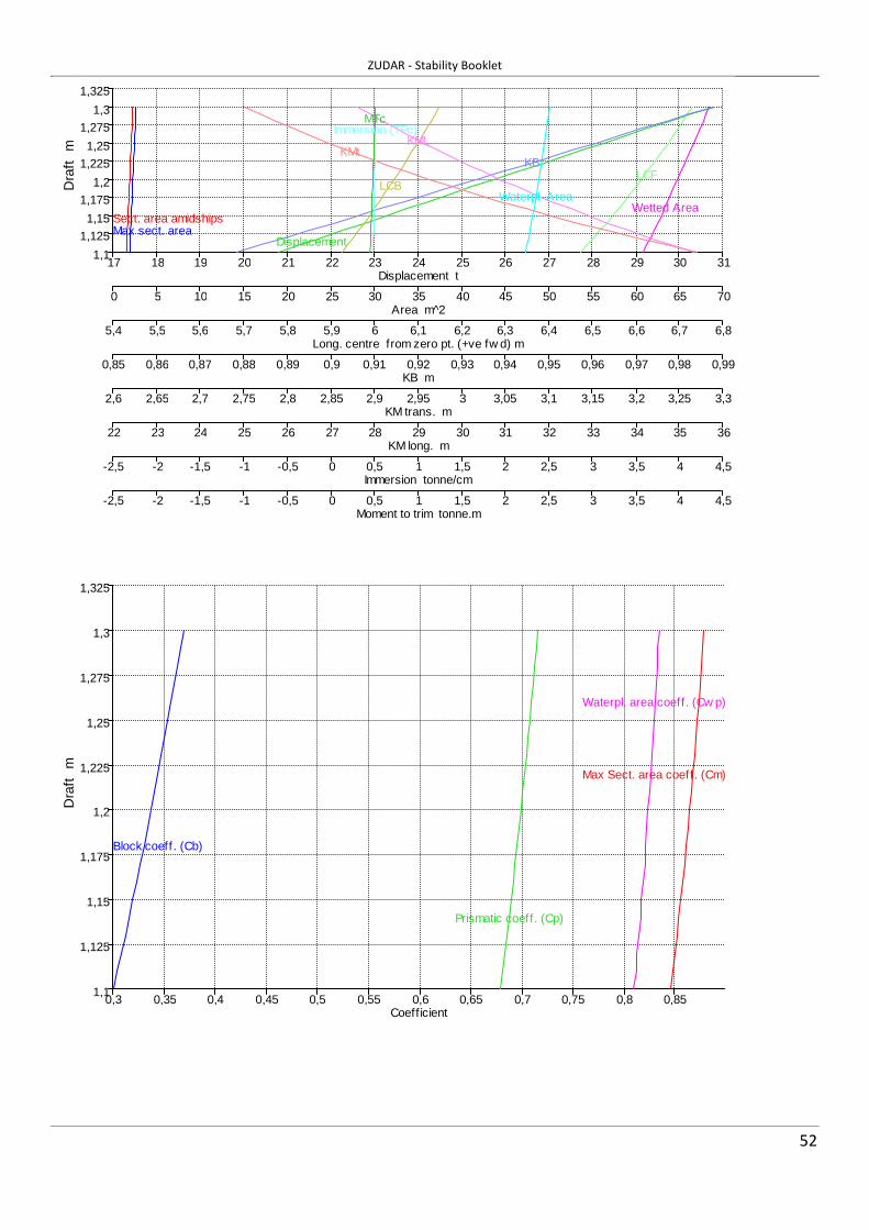
ZUDAR - Stability Booklet
52
1,1
1,125
1,15
1,175
1,2
1,225
1,25
1,275
1,3
1,325
17 18 19 20 21 22 23 24 25 26 27 28 29 30 31
0 5 10 15 20 25 30 35 40 45 50 55 60 65 70
5,4 5,5 5,6 5,7 5,8 5,9 6 6,1 6,2 6,3 6,4 6,5 6,6 6,7 6,8
0,85 0,86 0,87 0,88 0,89 0,9 0,91 0,92 0,93 0,94 0,95 0,96 0,97 0,98 0,99
2,6 2,65 2,7 2,75 2,8 2,85 2,9 2,95 3 3,05 3,1 3,15 3,2 3,25 3,3
22 23 24 25 26 27 28 29 30 31 32 33 34 35 36
-2,5 -2 -1,5 -1 -0,5 0 0,5 1 1,5 2 2,5 3 3,5 4 4,5
-2,5 -2 -1,5 -1 -0,5 0 0,5 1 1,5 2 2,5 3 3,5 4 4,5
DisplacementMax sect. areaSect. area amidships
Wetted AreaWaterpl. Area
LCBLCF
KBKMt
KMLImmersion (TPc)
MTc
Displacement t
Dra
ft
m
Area m^2
Long. centre from zero pt. (+ve fw d) m
KB m
KM trans. m
KM long. m
Immersion tonne/cm
Moment to trim tonne.m
1,1
1,125
1,15
1,175
1,2
1,225
1,25
1,275
1,3
1,325
0,3 0,35 0,4 0,45 0,5 0,55 0,6 0,65 0,7 0,75 0,8 0,85
Prismatic coeff. (Cp)
Block coeff. (Cb)
Max Sect. area coeff. (Cm)
Waterpl. area coeff. (Cw p)
Coefficient
Dra
ft
m

ZUDAR - Stability Booklet
53
7.2.1. HYDROSTATICS - TRIM 0,25M (BY STERN) Damage Case - Intact
Fixed Trim = 0,25 m (+ve by stern)
Specific gravity = 1,025; (Density = 1,025 tonne/m^3)
Draft Amidships
m
Displacement
t
LCB
from zero pt. (+ve fwd) m
VCB
m
LCF
from zero pt. (+ve fwd) m
KMt
m
KML
m
Immersion (TPc)
tonne/cm
MTc
tonne.m
RM at 1deg = GMt.Disp.sin(1)
tonne.m
1,100 21,01 5,823 0,882 6,441 3,243 34,651 0,483 0,455 0,793
1,110 21,50 5,837 0,888 6,457 3,209 34,157 0,485 0,459 0,798
1,120 21,98 5,850 0,893 6,473 3,175 33,684 0,487 0,462 0,804
1,130 22,47 5,864 0,899 6,489 3,143 33,227 0,489 0,466 0,809
1,140 22,96 5,878 0,904 6,503 3,111 32,772 0,490 0,470 0,814
1,150 23,45 5,891 0,910 6,518 3,081 32,345 0,492 0,473 0,819
1,160 23,94 5,904 0,915 6,533 3,053 31,934 0,493 0,477 0,825
1,170 24,44 5,917 0,921 6,546 3,024 31,517 0,495 0,480 0,829
1,180 24,93 5,929 0,926 6,559 2,998 31,159 0,496 0,484 0,835
1,190 25,43 5,942 0,931 6,571 2,971 30,766 0,498 0,487 0,840
1,200 25,93 5,954 0,937 6,586 2,947 30,404 0,499 0,491 0,845
1,210 26,43 5,966 0,942 6,600 2,923 30,054 0,501 0,494 0,851
1,220 26,93 5,978 0,948 6,612 2,899 29,692 0,502 0,497 0,856
1,230 27,43 5,990 0,953 6,626 2,877 29,363 0,504 0,501 0,861
1,240 27,94 6,001 0,959 6,637 2,855 29,020 0,505 0,504 0,866
1,250 28,44 6,013 0,964 6,646 2,834 28,717 0,506 0,507 0,872
1,260 28,95 6,024 0,969 6,660 2,814 28,417 0,508 0,511 0,878
1,270 29,46 6,035 0,975 6,671 2,795 28,101 0,509 0,514 0,883
1,280 29,97 6,046 0,980 6,684 2,776 27,818 0,510 0,517 0,889
1,290 30,48 6,056 0,986 6,694 2,758 27,519 0,511 0,520 0,894
1,300 30,99 6,067 0,991 6,705 2,740 27,227 0,513 0,523 0,899
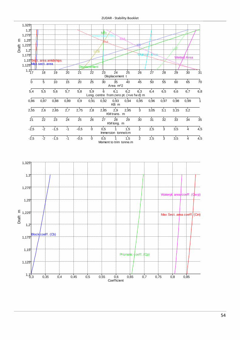
ZUDAR - Stability Booklet
54
1,1
1,125
1,15
1,175
1,2
1,225
1,25
1,275
1,3
1,325
17 18 19 20 21 22 23 24 25 26 27 28 29 30 31
0 5 10 15 20 25 30 35 40 45 50 55 60 65 70
5,4 5,5 5,6 5,7 5,8 5,9 6 6,1 6,2 6,3 6,4 6,5 6,6 6,7 6,8
0,86 0,87 0,88 0,89 0,9 0,91 0,92 0,93 0,94 0,95 0,96 0,97 0,98 0,99 1
2,55 2,6 2,65 2,7 2,75 2,8 2,85 2,9 2,95 3 3,05 3,1 3,15 3,2
21 22 23 24 25 26 27 28 29 30 31 32 33 34 35
-2,5 -2 -1,5 -1 -0,5 0 0,5 1 1,5 2 2,5 3 3,5 4 4,5
-2,5 -2 -1,5 -1 -0,5 0 0,5 1 1,5 2 2,5 3 3,5 4 4,5
DisplacementMax sect. areaSect. area amidships
Wetted AreaWaterpl. Area
LCBLCF
KBKMt
KMLImmersion (TPc)
MTc
Displacement t
Dra
ft
m
Area m^2
Long. centre from zero pt. (+ve fw d) m
KB m
KM trans. m
KM long. m
Immersion tonne/cm
Moment to trim tonne.m
1,1
1,125
1,15
1,175
1,2
1,225
1,25
1,275
1,3
1,325
0,3 0,35 0,4 0,45 0,5 0,55 0,6 0,65 0,7 0,75 0,8 0,85
Prismatic coeff. (Cp)
Block coeff . (Cb)
Max Sect. area coeff. (Cm)
Waterpl. area coeff . (Cw p)
Coefficient
Dra
ft
m

ZUDAR - Stability Booklet
55
8. TANK CALIBRATIONS
8.1. TANK CALIBRATIONS - FUEL
Fluid Type = Fuel Oil Specific gravity = 0,86
Permeability = 100 %
Trim = 0 m (+ve by stern); Heel = 0 deg to starboard
Tank Name Sounding m
Ullage m
% Full Capacity m^3
Capacity tonne
LCG m
TCG m
VCG m
FSM tonne.m
Fuel 1,000 0,000 100,000 2,376 2,043 9,660 0,000 1,447 0,000 0,982 0,018 98,000 2,328 2,002 9,660 0,000 1,438 1,606 0,981 0,019 97,900 2,326 2,000 9,660 0,000 1,437 1,606 0,950 0,050 94,391 2,242 1,928 9,660 0,000 1,421 1,606 0,900 0,100 88,781 2,109 1,814 9,660 0,000 1,396 1,606 0,850 0,150 83,172 1,976 1,699 9,660 0,000 1,370 1,606 0,800 0,200 77,563 1,843 1,585 9,660 0,000 1,345 1,606 0,750 0,250 71,954 1,709 1,470 9,660 0,000 1,319 1,606 0,700 0,300 66,344 1,576 1,355 9,660 0,000 1,293 1,606 0,650 0,350 60,735 1,443 1,241 9,660 0,000 1,267 1,606 0,600 0,400 55,126 1,310 1,126 9,660 0,000 1,241 1,606 0,550 0,450 49,516 1,176 1,012 9,660 0,000 1,214 1,606 0,500 0,500 43,907 1,043 0,897 9,660 0,000 1,187 1,606 0,450 0,550 38,298 0,910 0,782 9,660 0,000 1,159 1,606 0,400 0,600 32,689 0,777 0,668 9,660 0,000 1,131 1,606 0,350 0,650 27,079 0,643 0,553 9,660 0,000 1,101 1,606 0,300 0,700 21,719 0,516 0,444 9,660 0,000 1,071 1,216 0,250 0,750 16,855 0,400 0,344 9,660 0,000 1,040 0,894 0,200 0,800 12,490 0,297 0,255 9,660 0,000 1,011 0,635 0,150 0,850 8,621 0,205 0,176 9,660 0,000 0,981 0,432 0,100 0,900 5,250 0,125 0,107 9,660 0,000 0,953 0,277 0,050 0,950 2,376 0,056 0,049 9,660 0,000 0,926 0,165 0,022 0,978 1,000 0,024 0,020 9,660 0,000 0,911 0,118 0,000 1,000 0,000 0,000 0,000 9,660 0,000 0,900 0,000
0
10
20
30
40
50
60
70
80
90
100
0 0,1 0,2 0,3 0,4 0,5 0,6 0,7 0,8 0,9 1 1,1
0 0,25 0,5 0,75 1 1,25 1,5 1,75 2 2,25 2,5 2,75
-1 0 1 2 3 4 5 6 7 8 9 10
0 0,2 0,4 0,6 0,8 1 1,2 1,4 1,6 1,8 2 2,2
Sounding
Ullage
Capacity
LCG
TCG
VCG
FSM
Soundings & Ullage m
Fue
l %
Ful
l
Capacity tonne
Centre of Gravity m
Free Surface Moment tonne.m

ZUDAR - Stability Booklet
56
8.2. TANK CALIBRATIONS - FRESH WATER
Fluid Type = Fresh Water Specific gravity = 1
Permeability = 100 %
Trim = 0 m (+ve by stern); Heel = 0 deg to starboard
Tank Name Sounding m
Ullage m
% Full Capacity m^3
Capacity tonne
LCG m
TCG m
VCG m
FSM tonne.m
Fresh Water 0,720 0,000 100,000 0,304 0,304 11,700 0,000 1,360 0,000 0,700 0,020 99,103 0,301 0,301 11,700 0,000 1,357 0,016 0,684 0,036 98,000 0,298 0,298 11,700 0,000 1,353 0,025 0,683 0,037 97,900 0,298 0,298 11,700 0,000 1,353 0,025 0,650 0,070 94,642 0,288 0,288 11,700 0,000 1,342 0,025 0,600 0,120 88,275 0,268 0,268 11,700 0,000 1,322 0,033 0,550 0,170 80,850 0,246 0,246 11,700 0,000 1,298 0,038 0,500 0,220 72,933 0,222 0,222 11,700 0,000 1,274 0,041 0,450 0,270 64,768 0,197 0,197 11,700 0,000 1,248 0,042 0,400 0,320 56,564 0,172 0,172 11,700 0,000 1,223 0,042 0,350 0,370 48,359 0,147 0,147 11,700 0,000 1,197 0,042 0,300 0,420 40,154 0,122 0,122 11,700 0,000 1,171 0,042 0,250 0,470 31,950 0,097 0,097 11,700 0,000 1,144 0,042 0,200 0,520 23,841 0,072 0,072 11,700 0,000 1,116 0,041 0,150 0,570 16,144 0,049 0,049 11,700 0,000 1,088 0,038 0,100 0,620 9,144 0,028 0,028 11,700 0,000 1,059 0,033 0,050 0,670 3,239 0,010 0,010 11,700 0,000 1,030 0,025 0,022 0,698 1,000 0,003 0,003 11,700 0,000 1,013 0,016 0,000 0,720 0,000 0,000 0,000 11,700 0,011 1,000 0,000
0
10
20
30
40
50
60
70
80
90
100
0 0,1 0,2 0,3 0,4 0,5 0,6 0,7 0,8 0,9 1 1,1 1,2
0 0,03 0,06 0,09 0,12 0,15 0,18 0,21 0,24 0,27 0,3 0,33 0,36
0 1 2 3 4 5 6 7 8 9 10 11 12
0 0,025 0,05 0,075 0,1 0,125 0,15 0,175 0,2 0,225 0,25 0,275 0,3
Sounding
Ullage
Capacity
LCG
TCG
VCG
FSM
Soundings & Ullage m
Fre
sh W
ater
%
Ful
l
Capacity tonne
Centre of Gravity m
Free Surface Moment tonne.m

ZUDAR - Stability Booklet
57
9. PLANS/DIAGRAMS TO INSERT IN THE REPORT
9.1. TANK DEFINITION:
Name Type Specific
gravity
Fluid
type
Aft
m
Fore
m
F.Port
m
F.Stbd.
m
F.Top
m
F.Bott.
m
Fuel Tank 0,86 Fuel Oil 9,2 10,119 -1,45 1,45 1,9 0,9
Fresh Water Tank 1 Fresh Water 11,45 11,949 -0,5 0,5 1,72 1

ZUDAR - Stability Booklet
58
9.2. GENERAL ARRANGEMENT

1
Wolters, Klaas
From: Wolters, KlaasSent: 16 May 2017 10:54To: '[email protected]'Cc: Simon, Uwe; Hoenig, Joerg; '[email protected]'Subject: HPC-1750054-28515-17-KWo – Inclining Test Report (Final) - ZUDARAttachments: ZUDAR - Inclining test report_ex.pdf
Importance: High
Our Ref.: HPC/1750054/28515‐17/KWo – Inclining Test Report (Final) Your Ref.: Pilot Boat – ZUDAR ‐ IMO No. 8683080 Dear Mr. Hey, 1. Reference is made to your email including the inclining test report for subject vessel. 2. Please be informed that the inclining test report, based on the test carried out on the 02nd March 2017, has been seen and found acceptable to justify the following lightweight details to be used in the final “Trim & Stability Booklet”: Lightweight: 23.270 tonnes LCG: 6.510 meters fwd. of AP TCG: 0.000 meters on CL VCG: 1.810 meters above base line 3. The accepted inclining test report as well as a copy of this email must be included in the final “Trim & Stability Booklet”. Further, loading conditions etc. must reflect the lightship details derived from the inclining test report. 4. It is noted that the physical initial heel during the inclining experiment of ‐0.45° was omitted and calculation have been performed with 0 heel. The master is responsible to ensure an upright floating position and that unfavourable heeling angles will be corrected. 5. Please find attached an accepted, stamped copy of the inclining test report dated 03rd April 2017, for the vessel. In case you have any questions, please do not hesitate to contact me. Best regards,
Klaas Wolters Specialist Statutory Services Lloyd’s Register Marine E: [email protected] T: +49 (0)40 328 107-137 Lloyd’s Register EMEA Niederlassung Deutschland. Am Sandtorkai 41, 20457 Hamburg, Germany Visit www.lr.org or follow us on: Twitter LinkedIn Facebook Working together for a safer world Lloyd’s Register and variants of it are trading names of Lloyd’s Register Group Limited, its subsidiaries and affiliates. Lloyd’s Register EMEA (Reg. no. 29592 R) is a registered society under the Co-operative and Community Benefit Societies Act 2014 in England and Wales. Registered office: 71 Fenchurch Street, London, EC3M 4BS, UK. A member of the Lloyd’s Register group.

2
Lloyd's Register Group Limited, its subsidiaries and affiliates and their respective officers, employees or agents are, individually and collectively, referred to in this clause as 'Lloyd's Register'. Lloyd's Register assumes no responsibility and shall not be liable to any person for any loss, damage or expense caused by reliance on the information or advice in this document or howsoever provided, unless that person has signed a contract with the relevant Lloyd's Register entity for the provision of this information or advice and in that case any responsibility or liability is exclusively on the terms and conditions set out in that contract.

INCLINING TEST REPORT
ZUDAR
CREATE BY: Jakub Handke
CHECKED BY: Wojciech Kotłowski
LATEST AMENDMENT: 3-Apr-17
REVISION NUMBER: REV
1
LR051.2013.12
SEEN ANDACCEPTEDSeen and accepted by:See email dated:Date:Initials:
Marine, Hamburg Technical Support Office Statutory - STAT
Klaas WoltersMay-16, 2017May-16, 2017KWo
Lloyd's Register EMEA
Our Ref.:HPC/1750054/28515-17/KWo

Ship name: ZUDARDate: 02-03-2017Location: Wolgast, GermanyReport prepared by: J. HandkeReport aproved by: W. Kotłowski
TABLE OF CONTENTS
Chapter: Page:DATA 3GENERAL 3WATER DENSITY 3DROUGHT 4DISPLACEMENT 5INCLINING WEIGTHS 6PENDULUM 6PENDULUM DEVIATION 7ANGLES CALCULATION 8ADDITIONAL WEIGHTS 9MISSING WEIGHTS 10TANKS CONTENTS - FREE SURFACE EFFECT 11CALCULATIONS 12RESULTS FOR SHIP DURING TEST 13RESULTS FOR LIGHT SHIP 13
2

DATA
Name of ship: ZUDARIMO Number 8683080International Call Sign DKCL2Owner: Lotsbetrieb GmbH MVBuild Ostsee-Werft K.Vertens G.m.b.HYear of build: 1983Year of conversion: 2016Class Society Lloyd's Register Flag State GermanyMain dimensions:
LOA mLWL mLBP mB mD MLD m
GENERAL
Date: 02-03-2017Location: Wolgast, GermanyStart time:End time:Wind speed: calm m/sWind direction:Sea state:Current speed: m/sCurrent direction:Water depth: mWater temperature: °C
Mooring description:
WATER DENSITY
1 2 3 4 5LocationMeasure 1.001
17.30
15.504.102.07
Measure
1.001
2 m from shore
Mean density:
15.00
3

DROUGHT
Drought measured in milimeters.
Heel=0 is taken for calculations
Midship Fore perpendicular
12711208
Heel deg (+ to STBD)
-0.45
1144
Aft perpendicularDraught at perpendiculars
4

DISPLACEMENT
Calculated in Maxsurf Stability
ttt
Total displacement includes correction for appendages.
Draft
Amidships
m
Displacem
ent tHeel deg
Draft at FP
m
Draft at AP
m
Draft at
LCF m
Trim (+ve
by stern)
m
WL
Length m
Beam max
extents on
WL m
1.208 24.41 0 1.271 1.144 1.2 -0.127 15.625 3.824
Wetted
Area m^2
Waterpl.
Area m^2
Prismatic
coeff. (Cp)
Block
coeff. (Cb)
Max Sect.
area coeff.
(Cm)
Waterpl.
area coeff.
(Cwp)
LCB from
zero pt.
(+ve fwd)
m
LCF from
zero pt.
(+ve fwd)
m
KB m
65.62 49.906 0.77 0.348 0.468 0.835 6.694 6.806 0.924
KG m BMt m BML m GMt m GML m KMt m KML m
Immersion
(TPc)
tonne/cm
MTc
tonne.m
0 2.129 32.851 2.998 33.72 3.053 33.774 0.5 0.531
RM at
1deg =
GMt.Disp.
sin(1)
tonne.m
Max deck
inclination
deg
Trim angle
(+ve by
stern) deg
1.277 0.4694 -0.4694
Calculations performed for water density ρ=1,00t/m³
DisplacementCalculated:Correction:
Total:
24.410.1224.53
From Maxsurf Stability calculations
5

INCLINING WEIGTHS
Group Mass LCG TCG VCG[t] [m] [m] [m]
1 0.3 0.700 -1.3 2.212 0.3 1.700 1.61 2.213 0.25 13.750 0 2.824
(+) by Star board (-) by Port side
No Mass groups Arm MovedPORT CL STBD [m] mass
0 1 3 21 1,2 3 -3.23 22 1,2,3 -1.37 33 2,3 1 2.625 14 3 1,2 3.22 25 3 1,2 1.37 36 1,2,3 1.34 37 1 2,3 -2.6 18 1 3 2 -1.34 3
(+) move in Star board direction (-) move in Port side direction
PENDULUM
No
3.805Mast, behind wheelhouse
Movements of inclining weights
2
2.8731Battery locker at aft
Location Lenght [m]
Groups
6

PENDULUM DEVIATION
PORT STBD PORT STBD PORT STBD PORT STBD PORT STBD S/n
845 855 846 854 850 859 842 858 845 855 850.9
750 780 758 775 755 765 755 765 754 773 763
720 740 728 732 720 735 728 732 728 728 729.1
800 809 804 806 805 805 805 808 803 805 805
894 905 890 900 890 898 891 899 894 897 895.8
922 929 922 926 924 924 922 924 922 925 924
948 957 945 954 948 953 948 955 949 955 951.2
872 877 875 879 875 877 875 877 875 877 875.9
841 850 850 853 845 850 846 859 850 860 850.4
Measurement 2
Measurement 3
Measurement 4
Pendulum deviation
Measurement 5
Measurement 6
Measurement 7
Measurement 8
Measurement 9
Pendulum number: 1 Pendulum length: 2.87
Measurement 1
7

PORT STBD PORT STBD PORT STBD PORT STBD PORT STBD S/n
770 782 779 790 780 786 780 788 770 789 781.4
658 670 660 668 656 674 650 670 652 667 662.5
612 628 600 631 609 630 611 629 614 627 619.1
710 734 712 728 715 729 719 731 714 727 721.9
842 851 844 850 840 850 839 855 832 856 845.9
874 890 870 896 881 894 882 891 879 894 885.1
905 931 920 931 918 927 914 930 911 934 922.1
810 834 820 831 822 833 818 830 819 832 824.9
770 799 776 796 779 791 782 797 779 789 785.8
ANGLES CALCULATION
1 2Length: 2.87 [m] Length: 3.81 [m]
ai /ai+1-ai/ tgα= ai /ai-ai+1/ tgα= tgα=
1 850.9 0.0 0.0000 781.4 0.0 0.0000 0.0000
2 763.0 -87.9 -0.0306 662.5 -118.9 -0.0312 -0.0309
3 729.1 -33.9 -0.0118 619.1 -43.4 -0.0114 -0.0116
4 805.0 75.9 0.0264 721.9 102.8 0.0270 0.0267
5 895.8 90.8 0.0316 845.9 124.0 0.0326 0.0321
6 924.0 28.2 0.0098 885.1 39.2 0.0103 0.0101
7 951.2 27.2 0.0095 922.1 37.0 0.0097 0.0096
8 875.9 -75.3 -0.0262 824.9 -97.2 -0.0255 -0.0259
9 850.4 -25.5 -0.0089 785.8 -39.1 -0.0103 -0.0096
Pendulum deviationPendulum number:
Measurement 8
Measurement 9
Pendulum:Average
No
Pendulum:
Measurement 2
Measurement 3
Measurement 4
Measurement 5
Measurement 6
Measurement 7
2 Pendulum length: 3.805
Measurement 1
8

ADDITIONAL WEIGHTS
Location Massframe t x [m] y [m] z ABL [m]Mx My Mz
1 Fuel 0.966 9.660 0.000 1.450 9.332 0.000 1.4012 Fresh water 0.300 11.700 0.000 1.360 3.510 0.000 0.4083 0.000 0.000 0.0004 0.000 0.000 0.0005 0.000 0.000 0.0006 0.000 0.000 0.0007 0.000 0.000 0.0008 0.000 0.000 0.0009 0.000 0.000 0.000
101112131415161718192021222324252627282930313233343536373839404142434445
DescriptionNoMoment [tm]Arm [m]
9

MISSING WEIGHTS
Location Massframe t x [m] y [m] z ABL [m]Mx My Mz
123456789
101112131415161718192021222324252627282930313233343536373839404142434445
No DescriptionArm [m] Moment [tm]
10

TANKS CONTENTS - FREE SURFACE EFFECT
Breadth Length
of FS bT[m]
of FS cT[m]
1 Fuel 9 10 2.90 0.92 0.15812 Fresh water 1 12 1.00 0.50 0.01043 04 05 06 07 08 09 0
10 011 012 013 014 015 016 017 018 019 020 021 022 023 024 025 026 027 028 029 030 031 032 033 034 035 036 037 038 039 040 041 042 043 044 045 0
Density
ρ [t/m³]
0
000
000
00
000
000
000
000
000
000
000
000
000
000
00
1.00 0.0104170
0
Moment [m⁴]
i=cTbT³/12 ρi
0.1881830.84
No Tank
Location
frame
11

CALCULATIONS
D=
GMi= Error E=
Mass Arm Moment M/Dtgϕ GMi-GM
1 0 0.00 0.0000 0.0000 0.00000 0.00000 0.00000
2 0.3 -3.23 -0.9690 -0.0309 1.27740 -0.01945 0.00038
3 0.25 -1.37 -0.3425 -0.0116 1.20327 -0.09357 0.00876
4 0.3 2.63 0.7875 0.0267 1.20148 -0.09536 0.00909
5 0.3 3.22 0.9660 0.0321 1.22683 -0.07002 0.00490
6 0.25 1.37 0.3425 0.0101 1.38796 0.09112 0.00830
7 0.25 1.34 0.3350 0.0096 1.42309 0.12624 0.01594
8 0.3 -2.60 -0.7800 -0.0259 1.22868 -0.06816 0.00465
9 0.25 -1.34 -0.3350 -0.0096 1.42605 0.12920 0.01669
Total: 10.37476 0.06871
Control plot for pendulum 10.0000 0.0000 -0.96900 -0.0306 0.00000 0.00000
-0.9690 -0.0306 -0.78000 -0.0262 -0.96900 -0.03060
-0.3425 -0.0118 -0.34250 -0.0118 -1.31150 -0.04239
0.7875 0.0264 -0.33500 -0.0089 -0.52400 -0.01598
0.9660 0.0316 0.00000 0 0.44200 0.01563
0.3425 0.0098 0.33500 0.00947 0.78450 0.02544
0.3350 0.0095 0.34250 0.00982 1.11950 0.03491
-0.7800 -0.0262 0.78750 0.02642 0.33950 0.00870
-0.3350 -0.0089 0.96600 0.0316 0.00450 -0.00017
Control plot for pendulum 20.0000 0.0000 -0.9690 -0.0312 -0.96900 -0.03125
-0.9690 -0.0312 -0.7800 -0.0255 -0.78000 -0.02555
-0.3425 -0.0114 -0.3425 -0.0114 -0.34250 -0.01141
0.7875 0.0270 -0.3350 -0.0103 -0.33500 -0.01028
0.9660 0.0326 0.0000 0.0000 0.00000 0.00000
0.3425 0.0103 0.3350 0.0097 0.33500 0.00972
0.3350 0.0097 0.3425 0.0103 0.34250 0.01030
-0.7800 -0.0255 0.7875 0.0270 0.78750 0.02702
-0.3350 -0.0103 0.9660 0.0326 0.96600 0.03259
No
Heel moment
tgϕ=tgα E2
Displacement [t]24.53
-0.04
-0.03
-0.02
-0.01
0
0.01
0.02
0.03
0.04
-1.50000 -1.00000 -0.50000 0.00000 0.50000 1.00000 1.50000
Heeling moment vs tgϕ
-0.0400
-0.0300
-0.0200
-0.0100
0.0000
0.0100
0.0200
0.0300
0.0400
-1.5000 -1.0000 -0.5000 0.0000 0.5000 1.0000 1.5000
Heeling moment vs tgϕ
12

1.29684 m
0.03503 -
2.7010 %
0.4000 %
1.0E-06 %
0.0003 %
KMT 3.053 m
0.00036 %
%
0.0402 m
0.0069 m
RESULTS FOR SHIP DURING TEST
GM= m
BM= m
Ψ= deg
LCB= 6.69 TCB= 0.00 KB= 0.92 m
X= 6.70 Y= 0.00 Z= 1.79 m
RESULTS FOR LIGHT SHIP
No Mass [t] LCG [m] TCG [m] VCG [m] MX [tm] MY [tm] MZ [tm]1 24.532 6.70 0.00 1.79 164.39 0.00 43.902 -1.266 10.14 0.00 1.43 -12.84 0.00 -1.813 0.000 0.00 0.00 0.00 0.00 0.00 0.00
VCG:
23.276.510.001.81
tmmm
-0.47
Additional weightsMissing weights
LIGHTSHIPMass:LCG:TCG:
Center of buoyancy
Center of gravity
Ship during testDescription
Error of weigth measurement ΔP/P=
Error of arms measurement ΔL/L=
Error of metacentric heigth
ΔGM/GM=
[(KMT/2GM)•tg2α] • 100% =
ΔD/D=
Average metacentric during the test
Error of test e=
Relative error of test e / GM • 100% =
Relative error of displacement
2.13BM=I/V
Trim angle (+ by stern) deg
Correction of total error of GM
Correction of Free surface moment
Metacentric height1.26
Heigth of metacentric point
Total error
sGM / GM = [ S/GM + DD/D + DP/P + DL/L + DGM/GM ] =
3.1016
13