zwx series - product.tdk.com · in c orrec t u sa ge c ou ld lea d t o a n elec t r i c a l sh ock...
TRANSCRIPT

A234-04-01D
TDK-Lambda ZWX Series Instruction Manual
ZWX Series ZWX180・240・300
Instruction Manual
-1-
TDK-Lambda ZWX Series Instruction Manual
BEFORE USING THE POWER SUPPLY UNIT
Be sure to read this instruction manual thoroughly before using this product. Pay attention to all cautions and warnings before using this product. Incorrect usage could lead to an electrical shock, damage to the unit or a fire hazard.
DANGER Never use this product in locations where flammable gas or ignitable substances are present. When a spark is generated, there are risks of igniting these substances and exploding.
WARNING
· This product is primarily designed and manufactured as Class 1 equipment. In the interest of safety, connect to earth before using the product. · Do not touch this product and the internal components in operation or shortly after shut down. They may have high voltage or high temperature and as
the product dissipates its heat so the surface of the product is hot. You may receive electric shock or burn. · When this product is operating, keep your hands and face away from it as you may be injured by flying debris in the event of a fault. · Do not make unauthorized changes to this product, otherwise you may receive electric shock and void your warranty. · Do not drop or insert anything into this product. It might lead to a failure, fire and/or electric shock. · Do not operate this product after it falls down. · Do not use this product in the event of the emission of smoke or abnormal smell and sound etc. It might lead to fire and/or electric shock. In such cases,
please contact us. Do not attempt repair by yourself, as it is dangerous for the user. · Do not operate this product in the presence of condensation. It might lead to fire and/or electric shock.
CAUTION · This power supply is designed for use within an end product. · Confirm connections to input/output terminals and signal terminals are correct as indicated in the instruction manual before switching on. · Input voltage, Output current, Output power, ambient temperature and ambient humidity should be kept within specifications, otherwise the product
will be damaged. · Do not operate and store this product in an environment where condensation might occur. In such case, waterproof treatment is necessary. · Do not use this product in environment with a strong electromagnetic field, corrosive gas or conductive substances. · For applications which require very high reliability (Nuclear related equipment, traffic control equipment, medical equipment, etc.), it is necessary to
provide a fail-safe mechanism in the end equipment. · Do not inject abnormal voltages into the output or signal of this product. The injection of reverse voltage or over voltage exceeding nominal output
voltage into the output or signal terminals might cause damage to internal components. · Never operate the product under over current or short-circuit conditions for more than 30 seconds, or outside its specified Input Voltage Range.
Insulation failure, smoking, burning or other damage may occur. · This product contains a printed circuit board utilizing surface mounted devices. PCB stress such as bending, twisting etc. could cause damage.
Therefore, please handle with care. · When handling this product, hold the board edge and take not to touch the component side. When installing this product in apparatus or equipment,
mount it on spacers. · The output of this product is considered to be a hazardous energy level (The voltage is 2V or more and the power is 240VA or more). It must not be
made accessible to users. Protection must be provided for Service Engineers against indirect contact with the output terminals and/or to prevent tools being dropped across them. While working on this product, the AC input power must be switched off and the input and output voltage should be zero.
· When using for personal computer (hereinafter called PC), cut input voltage with you may stop PC. When the AC switch is cut while PC is operating, PC might be damaged. Especially, when the AC switch is cut while the memory such as hard disks is operating, you may damage data in a PC.
· This product has used Power Thermistor to protect the circuit from Inrush Current. Frequent repetition of input might cause damage to internal components because of generating surge current.
· Breaking of internal fuse is considered internal failure. In such cases, please contact us. · The information in this document is subject to change without prior notice. Please refer to the latest version of the data sheet, etc., for the most up-to
date specifications of the product. · No part of this document may be copied or reproduced in any form without prior written consent of Densei-Lambda.
Note: CE MARKING CE Marking, when applied to a product covered by this handbook, indicates compliance with the low voltage directive.
-2-
TDK-Lambda ZWX Series Instruction Manual
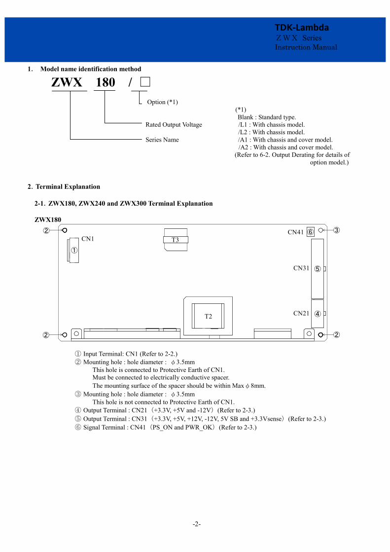
1. Model name identification method
ZWX 180 / □
Option (*1) (*1) Blank : Standard type.
Rated Output Voltage /L1 : With chassis model. /L2 : With chassis model. Series Name /A1 : With chassis and cover model. /A2 : With chassis and cover model. (Refer to 6-2. Output Derating for details of
option model.) 2.Terminal Explanation 2-1.ZWX180, ZWX240 and ZWX300 Terminal Explanation ZWX180
②
② ②
③
④
⑤
⑥
T2
T3CN1CN41
CN31
CN21
①
① Input Terminal: CN1 (Refer to 2-2.) ② Mounting hole : hole diameter : φ3.5mm
This hole is connected to Protective Earth of CN1. Must be connected to electrically conductive spacer. The mounting surface of the spacer should be within Maxφ8mm.
③ Mounting hole : hole diameter : φ3.5mm This hole is not connected to Protective Earth of CN1.
④ Output Terminal : CN21(+3.3V, +5V and -12V)(Refer to 2-3.) ⑤ Output Terminal : CN31(+3.3V, +5V, +12V, -12V, 5V SB and +3.3Vsense)(Refer to 2-3.) ⑥ Signal Terminal : CN41(PS_ON and PWR_OK)(Refer to 2-3.)

-3-
TDK-Lambda ZWX Series Instruction Manual
ZWX240 ②
② ②
②
③
④
⑤
T2
T3CN1 CN41
CN31
CN21
①
① Input Terminal : CN1(Refer to 2-2.) ② Mounting hole : hole diameter : φ3.5mm
This hole is connected to Protective Earth of CN1. Must be connected to electrically conductive spacer. The mounting surface of the spacer should be within Maxφ8mm.
③ Output Terminal : CN21(+3.3V, +5V and -12V)(Refer to 2-3.) ④ Output Terminal : CN31(+3.3V, +5V, +12V, -12V, 5V SB and +3.3Vsense)(Refer to 2-3.) ⑤ Signal Terminal : CN41(PS_ON and PWR_OK)(Refer to 2-3.)
ZWX300
②
② ②
②
③
④
⑤
T2
T3CN1 CN41
CN31
CN21
⑥CN51
①
① Input Terminal : CN1 (Refer to 2-2.) ② Mounting hole : hole diameter : φ3.5mm
This hole is connected to Protective Earth of CN1. Must be connected to electrically conductive spacer. The mounting surface of the spacer should be within Maxφ8mm.
③ Output Terminal : CN21(+3.3V, +5V and +12V-1)(Refer to 2-3.) ④ Output Terminal : CN31(+3.3V, +5V, +12V-1, -12V, 5V SB and +3.3Vsense)(Refer to 2-3.) ⑤ Signal Terminal : CN41(PS_ON and PWR_OK)(Refer to 2-3.) ⑥ Output Terminal : CN51(+12V-2)(Refer to 2-3.)

-4-
TDK-Lambda ZWX Series Instruction Manual
2-2. CN1 Connector pin Assign and Function (ZWX Series) CN1
5
3
1
Pin No. Function Note
1 L AC Input terminal Live line Fuse in line
3 N AC Input terminal Neutral line -
5 Terminal (Protective earth) -
2-3. CN21, CN31, CN41 and CN51 Connector pin Assign and Function (ZWX Series)
CN21
Pin No. Function
1 +3.3V +3.3V output terminal 2 +5V +5V output terminal 3 COM GND terminal (All of COM are connected in this Power supply unit.) 4 COM GND terminal (All of COM are connected in this Power supply unit.)
5 +12V +12V output terminal (ZWX180 and ZWX240)
+12V-1 +12V output terminal (ZWX300 only) 6 N.C. No connect (Connected to +3.3V inside.) 7 +5V +5V output terminal 8 COM GND terminal (All of COM are connected in this Power supply unit.) 9 COM GND terminal (All of COM are connected in this Power supply unit.)
10 +12V +12V output terminal (ZWX180 and ZWX240)
+12V-1 +12V output terminal (ZWX300 only)
CN31
Pin No. Function
1 +12V +12V output terminal (ZWX180 and ZWX240)
+12V-1 +12V output terminal (ZWX300 only) 2 COM GND terminal (All of COM are connected in this Power supply unit.) 3 +3.3V +3.3V output terminal 4 +3.3V +3.3V output terminal 5 +3.3V sense +3.3V output Sensing terminal 6 -12V -12V output terminal 7 COM GND terminal (All of COM are connected in this Power supply unit.) 8 COM GND terminal (All of COM are connected in this Power supply unit.) 9 +5V +5V output terminal
10 +5V +5V output terminal
11 +5V SB +5V SB output terminal
12 +12V +12V output terminal (ZWX180 and ZWX240)
+12V-1 +12V output terminal (ZWX300 only) 13 COM GND terminal (All of COM are connected in this Power supply unit.) 14 +3.3V +3.3V output terminal 15 +3.3V +3.3V output terminal 16 COM GND terminal (All of COM are connected in this Power supply unit.) 17 COM GND terminal (All of COM are connected in this Power supply unit.) 18 COM GND terminal (All of COM are connected in this Power supply unit.) 19 COM GND terminal (All of COM are connected in this Power supply unit.)
20 +5V +5V output terminal
21 +5V +5V output terminal
22 +5V +5V output terminal

-5-
TDK-Lambda ZWX Series Instruction Manual
CN41
Pin No. Function
1 PWR_OK PWR_OK signal terminal
2 PS_ON PS_ON signal terminal
(ZWX300 only) CN51
Pin No. Function 1 COM GND terminal (All of COM are connected in this Power supply unit.) 2 COM GND terminal (All of COM are connected in this Power supply unit.) 3 +12V-2 +12V output terminal (ZWX300 only) 4 +12V-2 +12V output terminal (ZWX300 only)
*Output current of each connector pin must be less than 9A. 3.Terminal Connecting Method
Take care about the input wiring. Wrong connection cause the power supply spoil. · Input must be off when making connections. · Connect terminal of input connector and mounting hole to protective earth of the equipment. · The output load line and input line shall be separated to improve noise sensitivity. · When connecting or removing connector, do not apply stress to PCB. · Use the input/output connector specified in outline drawing. Also, use recommended crimping tool.
Connector is not included with this product. INPUT/OUTPUT CONNECTOR (Common ZWX Series)
CONNECTOR MACHING HOUSING TERMINAL PINS MANUFACT
INPUT TERMINAL (CN1) B3P5-VH(LF)(SN) VHR-5N AWG18-22 SVH-21T-P1.1 BVH-21T-P1.1 J.S.T.
OUTPUT TERMINAL (CN21) 5566-10A-210 5557-10R-210 AWG18-24 5556PBT, 5556PBTL MOLEX OUTPUT TERMINAL (CN31) 5566-22A-210 5557-22R-210 AWG18-24 5556PBT, 5556PBTL MOLEX
SIGNAL TERMINAL (CN41) B2B-XH-AM(LF)(SN) XHP-2 AWG22 BXH-001T-P0.6
J.S.T. SXH-001T-P0.6
OUTPUT TERMINAL (CN51) (ZWX300 only) 5566-04A-210 5557-04R-210 AWG18-24 5556PBT, 5556PBTL MOLEX

-6-
TDK-Lambda ZWX Series Instruction Manual
Common ZWX Series BASIC CONNECTION
CN41
CN31
CN21
CN51
1
11
2
12
1
1
2
3
4
22
1
5
6
10 Refer to fig. below
CN1
COMPONENT SIDE
BASIC CONNECTION OF OUTPUT SIDE
Load
Load
Load
Load
Load
Load
+12V-2 (ZWX300 only)
CN51 : 3, 4 Pin
+3.3V sense
CN31 : 5 Pin
+3.3V
CN21 : 1 PinCN31 : 3, 4, 14, 15 Pin
+5V
CN21 : 2, 7 PinCN31 : 9, 10, 20, 21, 22 Pin
+12V (ZWX180, 240)+12V-1 (ZWX300)
CN21 : 5, 10 PinCN31 : 1, 12 Pin
+5V SB
CN31 : 11 Pin
COM
CN21 : 3, 4, 8, 9 PinCN31 : 2, 7, 8, 13, 16, 17, 18, 19 PinCN51 : 1, 2 Pin
-12V
CN31 : 6 Pin
PS_ON
CN41 : 2 Pin
PWR_OK
CN41 : 1 PinSignal output
* All of COM are connected in this Power supply unit.

-7-
TDK-Lambda ZWX Series Instruction Manual
4. Specification of Input and Output Signal
T1
T5T3
T2
T4
Vin (AC)
PS_ON
PWR_OK
Vout +3.3VDC+5VDC+12VDC
95%
T6
T5T3
T2
95%
ON/OFF Contro l
0V
0V
Input & Shut down
Tim ing chart
T1 < 2s
T3 ≦ 10ms
100ms ≦ T2 ≦ 500ms
T4 ≧ 16msT5 ≧ 1msT6 < 500ms
Time characteristic of signal
V in (AC)
PS_ON
PWR_OK
Vout +3.3VDC+5VDC
+12VDC
4-1. PS_ON When the “L” is input, +3.3V, +5V, +12V (only ZWX300 has+12V-1, +12V-2) and –12V are output. When the “H” or “OPEN” is input, +3.3V, +5V, +12V (only ZWX300 has+12V-1, +12V-2) and –12V are stopped and reset the shut down latch.
PS_ON
COM
Output
ON
OFF
PS_ON Level to COM
Short or Low : 0V - 0.8V
Open or High : 2.0V - 5.5V
Control mode
1mA maxOperation Voltage : 5.5V max
4-2. PWR_OK When the input voltage and +5V output voltage become “ON", the "H" signal is output.
PWR_OK
COM
PWR_OK Signal
High (2.4V - 5.5V)
Low (<0.4V)
PS_ON Level to COM
Short or Low : 0V - 0.8V
Open or High : 2.0V - 5.5V
Output
ON
OFF
Sink Current : 5mA max
Operation Voltage : 5.5V max
-8-
TDK-Lambda ZWX Series Instruction Manual
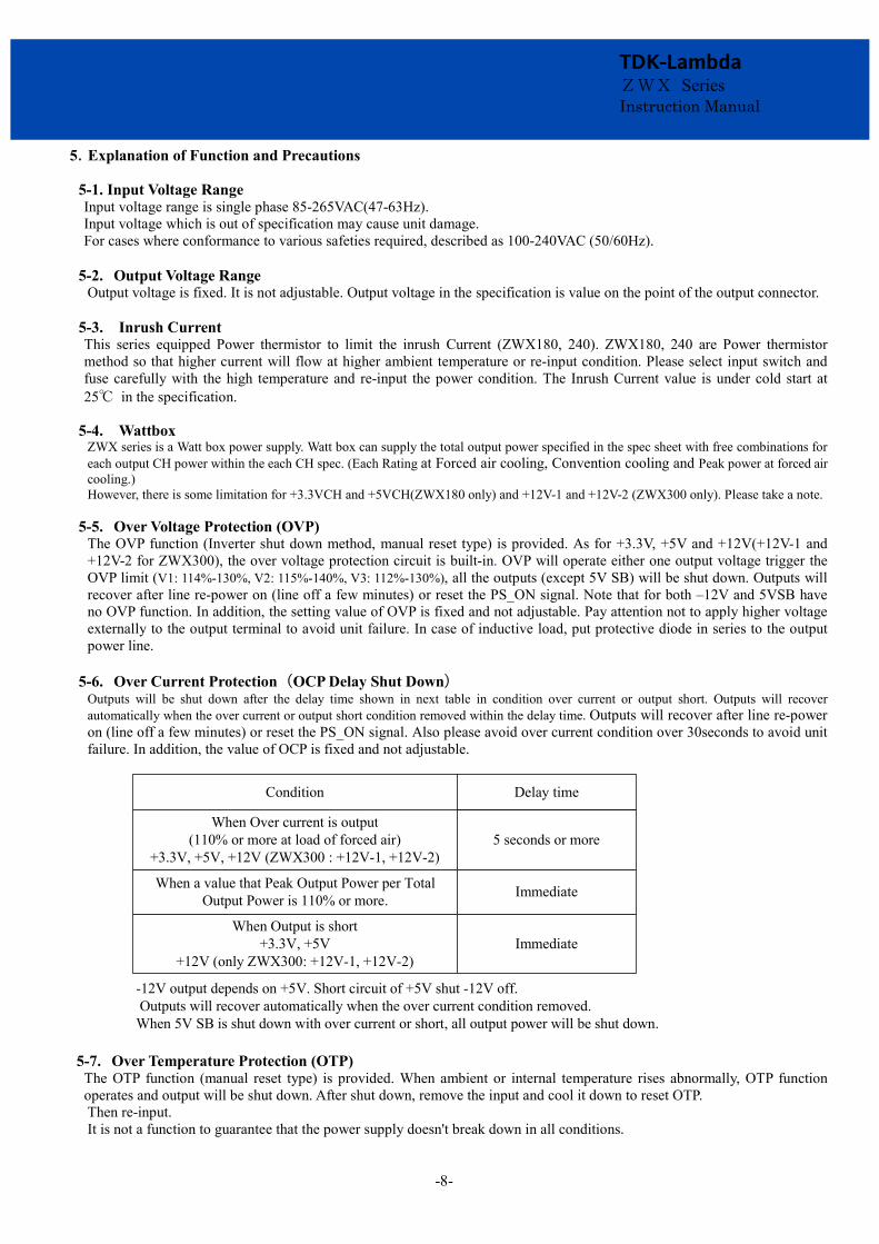
5.Explanation of Function and Precautions
5-1. Input Voltage Range Input voltage range is single phase 85-265VAC(47-63Hz). Input voltage which is out of specification may cause unit damage. For cases where conformance to various safeties required, described as 100-240VAC (50/60Hz).
5-2. Output Voltage Range
Output voltage is fixed. It is not adjustable. Output voltage in the specification is value on the point of the output connector.
5-3. Inrush Current This series equipped Power thermistor to limit the inrush Current (ZWX180, 240). ZWX180, 240 are Power thermistor method so that higher current will flow at higher ambient temperature or re-input condition. Please select input switch and fuse carefully with the high temperature and re-input the power condition. The Inrush Current value is under cold start at 25℃ in the specification.
5-4. Wattbox ZWX series is a Watt box power supply. Watt box can supply the total output power specified in the spec sheet with free combinations for each output CH power within the each CH spec. (Each Rating at Forced air cooling, Convention cooling and Peak power at forced air cooling.) However, there is some limitation for +3.3VCH and +5VCH(ZWX180 only) and +12V-1 and +12V-2 (ZWX300 only). Please take a note.
5-5. Over Voltage Protection (OVP)
The OVP function (Inverter shut down method, manual reset type) is provided. As for +3.3V, +5V and +12V(+12V-1 and +12V-2 for ZWX300), the over voltage protection circuit is built-in. OVP will operate either one output voltage trigger the OVP limit (V1: 114%-130%, V2: 115%-140%, V3: 112%-130%), all the outputs (except 5V SB) will be shut down. Outputs will recover after line re-power on (line off a few minutes) or reset the PS_ON signal. Note that for both –12V and 5VSB have no OVP function. In addition, the setting value of OVP is fixed and not adjustable. Pay attention not to apply higher voltage externally to the output terminal to avoid unit failure. In case of inductive load, put protective diode in series to the output power line.
5-6. Over Current Protection (OCP Delay Shut Down)
Outputs will be shut down after the delay time shown in next table in condition over current or output short. Outputs will recover automatically when the over current or output short condition removed within the delay time. Outputs will recover after line re-power on (line off a few minutes) or reset the PS_ON signal. Also please avoid over current condition over 30seconds to avoid unit failure. In addition, the value of OCP is fixed and not adjustable.
When Over current is output(110% or more at load of forced air)
+3.3V, +5V, +12V (ZWX300 : +12V-1, +12V-2)
When a value that Peak Output Power per Total Output Power is 110% or more.
When Output is short+3.3V, +5V
+12V (only ZWX300: +12V-1, +12V-2)
Condition Delay time
5 seconds or more
Immediate
Immediate
-12V output depends on +5V. Short circuit of +5V shut -12V off. Outputs will recover automatically when the over current condition removed.When 5V SB is shut down with over current or short, all output power will be shut down.
5-7. Over Temperature Protection (OTP)
The OTP function (manual reset type) is provided. When ambient or internal temperature rises abnormally, OTP function operates and output will be shut down. After shut down, remove the input and cool it down to reset OTP. Then re-input. It is not a function to guarantee that the power supply doesn't break down in all conditions.

-9-
TDK-Lambda ZWX Series Instruction Manual
5-8. Remote Sensing (only +3.3V) This function compensates voltage drop of wiring from output terminals to load terminals. Connect “+3.3V sense” terminal to “+3.3V” terminal. The total line voltage drop (+ side line and - side line) shall be less than 0.3V. In case that sensing lines are too long, it is necessary to put an electrolytic capacitor in following. If remote sensing terminals are opened, the stability and the accuracy of the output turns worse. Therefore, terminal “+3.3V sense” terminal, “+3.3V” terminal must be connected.
Load
+3.3V sense
+3.3V
COM -
+
5-9. Output Ripple & Noise The standard specification for maximum ripple value is measured according to measurement circuit specified by EIAJ-RC9131. When load lines are longer, ripple will becomes larger. In this case, electrolytic capacitor, film capacitor, etc. might be necessary to use across the load terminal. The output ripple cannot be measure accurately if the probe ground lead of oscilloscope is too long.
Load 1
A
C1
3.3V sense
+3.3V
150mmAWG18xN
C7
Load 2C2
+5V
C8
A
Load 3C3
+12V, +12V-1
C9
A
Load 5C5
-12V
C11
A
Load 6C6
+5V SB
C12
A
PS_ON
COM
1.5m 50Ω Cable R1
C11
R1 : 50ΩC11 : 4700pF
+12V-2 (ZWX300 only)
COM
COM
COM
COM
COM
C1,C2,C3,C4,C5,C6
C7,C8,C9,C10,C11,C12
Film Cap.
Elec. Cap.
0.1uF
100uF
Capacitance
OscilloscopeBandwidth : 100MHz
Load 4C4 C10
A
COM
*All of COM are connected in this Power supply unit

-10-
TDK-Lambda ZWX Series Instruction Manual
5-10. Peak Output Current For ZWX series, the relation between peak output current and peak output power (Wp) must satisfy formulas below. The mean output power during peak output (Wm) have to be less than total output power specified in the spec sheet (Wavg) in both cases for forced air cooling and convection cooling. Also operating time at peak output current (τ) should be less than 5sec, period (T) should be more than 10msec. (Forced Air Cooling : Duty≦50%, Convention Cooling : Duty≦10%)
0W
0W
aW
Wp
Wp Wm
Wm
τ
T
τ
T
Wave ≧ Wm = Wp ×τ
T
Duty = T
τ×100 (%)
Wave ≧ Wm = (Wp - a) ×τ
+ aT
Wp : Peak output power ( W ) Wavg : Total output power of Specification ( W ) Wm : Average output power ( W ) t : Pulse width of peak output power ( sec ) (Operating time at peak output) T : Period (sec)
5-11. Isolation Test
Isolation resistance between Output - (Protective Earth) is more than 100MΩ at 500VDC. For safety operation, voltage setting of DC isolation tester must be done before the test. Ensure that the unit is fully discharged after the test.
Output - (Protective Earth) : 500VDC More than 100MΩ
-12V
+3.3Vsense+3.3V
+5V+12V
COM
5V SB
(+12V-1,+12V-2)
PS_OKPWR_ON
AC(L)
AC(N)
Isolation Tester

-11-
TDK-Lambda ZWX Series Instruction Manual
5-12. Withstand Voltage This series is designed to withstand 3.0kVAC between input and output, 2.0kVAC between input and (Protective Earth) and
500VAC between output and (Protective Earth) each for 1 minute. When testing withstand voltage, set current limit of the
withstand voltage test equipment to 20mA (output - (Protective Earth): 100mA). The applied voltage must be gradually increased from zero to the testing value and then gradually decreased for shut down. When timer is used, the power supply may be damaged by high impulse voltage at timer switch on and off. Connect input and output as follows.
Input - Output : 3.0kVAC 1min ( 20mA) Input - (Protective Earth) : 2.0kVAC 1min ( 20mA )
-12V
+3.3Vsense+3.3V
+5V+12V
COM
5V SB
(+12V-1,+12V-2)
PS_OKPWR_ON
AC(L)
AC(N)
Whisstand Voltage tester
-12V
+3.3Vsense+3.3V
+5V+12V
COM
5V SB
(+12V-1,+12V-2)
PS_OKPWR_ON
AC(L)
AC(N)
Output - (Protective Earth) : 500VAC 1min (100mA)
-12V
+3.3Vsense+3.3V
+5V+12V
COM
5V SB
(+12V-1,+12V-2)
PS_OKPWR_ON
AC(L)
AC(N)
Note) This product have multilayer ceramic capacitor in secondary circuit to frame ground.
Some of the withstand voltage tester may generate high voltage at the matching with multilayer ceramic capacitor and may cause the unit damage. So, please check the waveform of test voltage.

-12-
TDK-Lambda ZWX Series Instruction Manual
6. Mounting Directions 6-1. Output Derating according to the Mounting Directions.
Recommended standard mounting method is (A). Method (B)-(E) are also possible. Refer to the derating below. The de-rating values are referred to in each forced air / convection rating as 100%.
ZWX180, 240, 300
CN1 (INPUT)
CN1
CN1
CN1
CN1
CN1
(A) Standard Mounting (B) (C) (D) (E) (F) Inhibit
6-2. Output Derating Standard type and with chassis type (/L1, /L2)
CONVECTION COOLING
100
120
80
60
40
20
0-10 0 20 40 5010 30 60 70 80
MOUNTING A
MOUNTING B-E
Load
(%)
Ta (℃)
Ta(℃) Mounting (A) Mounting (B)-(E)
Load (%)
-10 - +40
+50
+60
100
100
60
60
-
Load (%) is percent of total output power (Convection). Also apply Load(%) to maximum output current (Convection) and combined maximum output power (Convection).
FORCED AIR COOLING
100
120
80
60
40
20
0-10 0 20 40 5010 30 60 70 80
MOUNTING A-E
Ta(℃) Mounting(A)-(E)
Load (%)
-10 - +50
+60
+70
60
100
20
Ta (℃)
Load
(%)
Load (%) is percent of total output power (Forced air). Also apply Load(%) to maximum output current (Forced air) and combined maximum output power (Forced air).
Please make air flow to maintain Core of T2 temperature 75℃ and Core of T3 temperature 85℃. (*1) (Please let air (0.85m3/min (30cfm)) flow into the Component side.)
Air flow should cool down all the component evenly.
/L2/L1 L ChassisCN1 (INPUT)
-13-
TDK-Lambda ZWX Series Instruction Manual
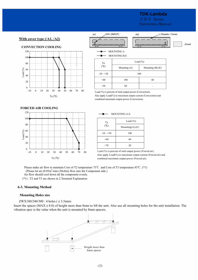
With cover type (/A1, /A2)
CONVECTION COOLING
100
120
80
60
40
0-10 0 20 40 5010 30 60 70 80
MOUNTING A
MOUNTING B-E
20
Load
(%)
Ta (℃)
Ta(℃) Mounting (A) Mounting (B)-(E)
Load (%)
-10 - +30
+40
+50
100
100
60
60
-
Load (%) is percent of total output power (Convection). Also apply Load(%) to maximum output current (Convection) and combined maximum output power (Convection).
FORCED AIR COOLING
100
120
80
60
40
20
0-10 0 20 40 5010 30 60 70 80
MOUNTING A-E
Ta(℃) Mounting(A)-(E)
Load (%)
-10 - +50
+60
+70
60
100
20
Ta (℃)
Load
(%)
Load (%) is percent of total output power (Forced air). Also apply Load(%) to maximum output current (Forced air) and combined maximum output power (Forced air).
Please make air flow to maintain Core of T2 temperature 75℃ and Core of T3 temperature 85℃. (*1) (Please let air (0.85m3/min (30cfm)) flow into the Component side.)
Air flow should cool down all the component evenly. (*1) : T2 and T3 are shown in 2.Terminal Explanation
6-3. Mounting Method
Mounting Holes size
ZWX180/240/300 : 4 holes (φ3.5mm) Insert the spacer (MAXφ8.0) of height more than 8mm to lift the unit. Also use all mounting holes for the unit installation. The vibration spec is the value when the unit is mounted by 8mm spacers.
Height more than 8mm spacer
/A1 /A2 L Chassis + Cover
…Cover
CN1 (INPUT)

-14-
TDK-Lambda ZWX Series Instruction Manual
And allowable area by metal pieces is 9mm from each PCB corners. Refer to figure below.
99
99
9 9
9 9
Condition to meet Insulation & Withstand Voltage standard.
More
tha
n
8mm
Component side
More
th
an
5m
m
Please leave 5mm space from the surfaces and left 5mm space from the sides of PCB, especially from the solder surface, 8mm space is necessary. If the space is not enough, the specification of insulation and withstand will not be satisfied. Please take the space in the power supply surroundings and the upper surface place of components to keep enough convection cooling.
(Protective Earth) should be connected to the earth terminal of the equipment. If not, the conducted noise and output noise will increase.
Metal spacer
Mountable FG
TerminalWire
Input
Chassis(Conductor)
Mor
e th
an 5
mm
Morethan 5mm
More than 5mm
Mor
e th
an 5
mm

-15-
TDK-Lambda ZWX Series Instruction Manual
Consider the heat radiation and safety when the power supply is used in that convection cooling. Please take a distance more than 15mm between the power supply and the peripheral parts. When lay out multiple units, please make sure to place 15mm or more space from each other.
Provide punching, etc. to allow air to flow
Air flow
Sheet metal
15mm or more 15mm or more
Note:Recommended torque for mounting screw. M3 screw : 0.49 Nm (5kgfcm) Penetration depth 6mm max in the power supply.
7. Wiring Method
(1) The output load line and input line shall be separated each other and twisted individually to improve noise. (2) Noise can be reduced by attaching a capacitor to the load terminals.
(3) For safety and EMI considerations, connect terminal of input connector and mountable Frame Ground of ZWX series to ground terminal at equipment firmly.
Connector manufacture method a). Applicable Wire and Crimping tool
b). Crimping Operation
Fig.1 : Examples of crimping Fig.2 : Examples of defective crimping
CONNECTOR TERMINAL PIN CRIPPING TOOL MANUFACTURE
Input Terminal (CN1) B3P5-VH(LF)(SN) AWG18-22 SVH-21T-P1.1
BVH-21T-P1.1 YC-160R J.S.T.
Output Terminal (CN21) 5566-10A-210 AWG18-24 5556PBT, 5556PBTL 57027-5000 MOLEX
Output Terminal (CN31) 5566-22A-210 AWG18-24 5556PBT, 5556PBTL 57027-5000 MOLEX
Output Terminal (CN41) B2B-XH-AM(LF)(SN) AWG22
SXH-001T-P0.6 YC-110R or YRS-110 J.S.T.
BXH-001T-P0.6 Output Terminal
(CN51) (OnlyZWX300)
5566-04A-210 AWG18-24 555PB6T, 5556PBTL 57027-5000 MOLEX

-16-
TDK-Lambda ZWX Series Instruction Manual
c). Inserting contact into housing Inserting crimped contact into housing (1) Do not apply any pulling force to crimped part, and insert contact parallel to housing (2) Insert contact into housing without stopping to innermost (3) Check secure locking per each insertion by pulling wire softly in order to check that contact does not come off housing. Besides, check whether there is the backlash in the direction of insertion axis.
d). Mating and Unmating Connector (1) Inserting connector
Hold receptacle housing securely and insert into header straight against to header post until click sounds. (2) Unmating connector Hold all wires securely and fix receptacle housing by fingers so as to pry, and then, withdraw it on the mating axis
e). Routing of Wire Routing wire so as not to apply external force to connector except force to such an extent that wire slightly buckles, considering an enough length to route and fixing of wire.
8. External Fuse Rating Refer to the following fuse rating when selecting the external fuses that are to be used on input line. Surge current flows when line turns on. Please use slow-blow or time-lag type fuse, not fast-blow fuse. Fuse rating is specified by in-rush current value at line turn-on. Do not select the fuse according to input current (RMS.) values under the actual load condition ZWX180: 6.3A ZWX240: 8.0A ZWX300: 10A

-17-
TDK-Lambda ZWX Series Instruction Manual
9.Before concluding that the unit is at fault
(1) Check if the rated input voltage is connected. (2) Check if the wiring of input and output is correct. (3) Check if the wire material is not too thin. (4) If use function of the +3.3V sense, check if the +3.3V sense connector is not opened. Control, check if the +3.3V
sense connector is not opened. If in open condition, output voltage accuracy turns worse. If use function of the PS_ON, check if the PS_ON connector is not opened. If in open condition, power supply will not output.
(5) Is the chassis of power supply hot abnormally? The output is shut down by OTP operation. (6) Please re-input after the unit to cool down sufficiently. The OTP function is provided. When ambient or internal
temperature rises abnormally, OTP function operates and output will be shut down. After shut down, remove the input and cool it down to reset OTP. Then re-input.
(7) Check if the output current and output wattage dose not over specification. (8) Audible noise can be heard when input voltage waveform is not sinusoidal. (9) Audible noise can be heard during Dynamic-Load operation. (10) Ensure that a large capacitor is not connected on the load side. (11) Please use it following, the stop of the output or the unstable operation might be caused. Please use within
maximum capacitance shown below. (12) Some consideration is necessary, if it connects over capacity of the following. Please inquire details of our
company.
+3.3V
+5V
+12V, +12V-1
+12V-2 (only ZWX300)
-12V
5V SB
6,000
10,000
5,000
3,000
350
350
Maximum capacitance on each output.
Output voltage capacitance (μF)
ZWX Series
(13) When external voltage of 3V or more is applied at the output terminals of 3.3V or 5V unit, sink current will flow when PS_ON signal is at OFF condition. Also, there is possibility that output voltage might not turn OFF (output voltage is continuous). In addition, customer device might be damaged due to sink current. Therefore, avoid injecting external voltage at the output terminals.
10. Range of free warranty
This product is warranted for a period of 3 years from the date of shipment. As for the breakdown under a normal use during free warranty term, repair is at free of charge.
Conditions of usage at the free of charge warranty are as follows. (1) Average operating temperature (ambient temperature of the power supply unit) is under 40ºC (2) Average load factor is less than 80% of each channel. (3) Installation method: Standard installation. Refer to Output derating for the load factor. Following cases are not covered by warranty. (1) Improper usage like dropping products, applying shock and defects from operation exceeding specification of the units. (2) Defects resulting from natural disaster (fire, flood).
Unauthorized modifications or repair by the buyers’ defects not cause by our company.