zxone 8000 intelligent optical transmission platform product description
TRANSCRIPT

ZXONE 8000Intelligent Optical Transmission Platform
Product Description
Version:V2.00
ZTE CORPORATIONNO. 55, Hi-tech Road South, ShenZhen, P.R.ChinaPostcode: 518057Tel: +86-755-26771900Fax: +86-755-26770801URL: http://ensupport.zte.com.cnE-mail: [email protected]
LEGAL INFORMATIONCopyright © 2013 ZTE CORPORATION.
The contents of this document are protected by copyright laws and international treaties. Any reproduction or
distribution of this document or any portion of this document, in any form by any means, without the prior written
consent of ZTE CORPORATION is prohibited. Additionally, the contents of this document are protected by
contractual confidentiality obligations.
All company, brand and product names are trade or service marks, or registered trade or service marks, of ZTE
CORPORATION or of their respective owners.
This document is provided “as is”, and all express, implied, or statutory warranties, representations or conditions
are disclaimed, including without limitation any implied warranty of merchantability, fitness for a particular purpose,
title or non-infringement. ZTE CORPORATION and its licensors shall not be liable for damages resulting from the
use of or reliance on the information contained herein.
ZTE CORPORATION or its licensors may have current or pending intellectual property rights or applications
covering the subject matter of this document. Except as expressly provided in any written license between ZTE
CORPORATION and its licensee, the user of this document shall not acquire any license to the subject matter
herein.
ZTE CORPORATION reserves the right to upgrade or make technical change to this product without further notice.
Users may visit ZTE technical support website http://ensupport.zte.com.cn to inquire related information.
The ultimate right to interpret this product resides in ZTE CORPORATION.
Revision History
Revision No. Revision Date Revision Reason
R1.0 20132-02-21 First release
Serial Number: SJ-20130221092619-001
Publishing Date: 2013-02-21(R1.0)
SJ-20130221092619-001|2013-02-21(R1.0) ZTE Proprietary and Confidential

ContentsAbout This Manual ......................................................................................... I
Chapter 1 Product Orientation and Application ...................................... 1-11.1 Product Orientation ............................................................................................ 1-1
1.2 Networking Application ....................................................................................... 1-3
1.2.1 Point-to-Point Network.............................................................................. 1-3
1.2.2 Chain Network ......................................................................................... 1-3
1.2.3 Ring Network ........................................................................................... 1-3
1.2.4 Ring-Chain Network ................................................................................. 1-4
1.2.5 Tangent Ring Network .............................................................................. 1-4
1.2.6 Cross Network ......................................................................................... 1-5
1.2.7 Mesh Network.......................................................................................... 1-5
1.3 Network Element Type........................................................................................ 1-5
1.3.1 OTM Configurations ................................................................................. 1-5
1.3.2 FOADM Configurations........................................................................... 1-13
1.3.3 ROADM Configurations .......................................................................... 1-17
1.3.4 OLA Configurations ................................................................................ 1-25
Chapter 2 Product Characteristics ........................................................... 2-12.1 Technology Characteristics ................................................................................. 2-1
2.2 Upgrade and Maintenance Characteristics ......................................................... 2-10
Chapter 3 System Functions..................................................................... 3-13.1 Line Transmission Function ................................................................................ 3-1
3.1.1 Transmission Capacity.............................................................................. 3-1
3.1.2 Channel Rate........................................................................................... 3-1
3.1.3 Channel Spacings .................................................................................... 3-2
3.1.4 Transmission System Codes..................................................................... 3-2
3.2 Automatic Power Optimization Function............................................................... 3-5
3.2.1 OMS Power Management......................................................................... 3-5
3.2.2 OCH Power Management ......................................................................... 3-5
3.3 IWF Function ..................................................................................................... 3-6
3.4 Wavelength Tunable Function ............................................................................. 3-6
3.5 Chromatic Dispersion Compensation................................................................... 3-7
3.6 Service Functions............................................................................................... 3-7
3.6.1 Service Access Function........................................................................... 3-7
I
SJ-20130221092619-001|2013-02-21(R1.0) ZTE Proprietary and Confidential
3.6.2 Service Convergence Function.................................................................. 3-8
3.7 Communication and Supervision Function ........................................................... 3-9
3.7.1 Supervisory Channels............................................................................... 3-9
3.7.2 Communication Functions....................................................................... 3-10
3.8 Alarm Monitoring Function .................................................................................3-11
3.8.1 External Alarm Input and Output Function.................................................3-11
3.8.2 Internal Alarm Monitoring Function ...........................................................3-11
3.9 Protection Functions......................................................................................... 3-12
3.9.1 SNP 1+1 Protection................................................................................ 3-12
3.9.2 Cross-Connect Board 1+1/2:2/4:2 Protection ........................................... 3-13
3.9.3 OMS 1+1 Protection ............................................................................... 3-13
3.9.4 OCH 1+1 Protection ............................................................................... 3-15
3.9.5 Two-Fiber Bidirectional OCH Shared Protection ....................................... 3-15
3.9.6 Chain Network-Based Electrical Layer 1+1 Wavelength Protection ............ 3-16
3.9.7 Ring Network-based Electrical Layer Two-Fiber Bidirectional ChannelShared Protection ................................................................................. 3-17
3.9.8 Protection Capability for EMS Channel .................................................... 3-19
3.10 Clock Management Function........................................................................... 3-19
3.11 Clock Synchronization Function....................................................................... 3-19
Chapter 4 Hardware Architecture ............................................................. 4-14.1 Product Appearance........................................................................................... 4-1
4.2 Board ................................................................................................................ 4-2
Chapter 5 Software Architecture............................................................... 5-15.1 Software Architecture Overview .......................................................................... 5-1
5.2 EMS Software.................................................................................................... 5-1
5.3 NE Control and Processing Software................................................................... 5-2
5.4 Board Software .................................................................................................. 5-4
5.5 Communication Protocols and Interfaces ............................................................. 5-4
Chapter 6 Technical Specifications .......................................................... 6-16.1 Requirements on Operating Wavelength.............................................................. 6-1
6.1.1 Allocation of Continuous Wavelengths ....................................................... 6-1
6.1.2 Allocation of Uncontinuous Wavelengths.................................................... 6-5
6.2 Service Access and Convergence Subsystem Specifications ................................ 6-7
6.2.1 Board Types ............................................................................................ 6-7
6.2.2 2.5G Board Specifications......................................................................... 6-7
6.2.3 10G Board Specifications........................................................................ 6-10
6.2.4 40G Board Specifications........................................................................ 6-12
II
SJ-20130221092619-001|2013-02-21(R1.0) ZTE Proprietary and Confidential

6.2.5 100 G Board Specifications..................................................................... 6-14
6.3 Optical Mux/DeMux Subsystem Specifications .................................................. 6-15
6.3.1 SOAD Board Specifications .................................................................... 6-15
6.3.2 OMU Board Specifications ...................................................................... 6-17
6.3.3 ODU Board Specifications ...................................................................... 6-18
6.3.4 ODUB Board Specifications .................................................................... 6-19
6.3.5 OCI Board Specifications........................................................................ 6-20
6.3.6 VMUX Board Specifications .................................................................... 6-20
6.3.7 VMUXB Board Specifications .................................................................. 6-21
6.3.8 SSDM Board Specifications .................................................................... 6-21
6.3.9 SOGMD Board Specifications ................................................................. 6-22
6.3.10 WBU Board Specifications ................................................................... 6-23
6.3.11 WSU Board Specifications .................................................................... 6-23
6.3.12 WBM Board Specifications.................................................................... 6-25
6.3.13 PDU Board Specifications ..................................................................... 6-26
6.4 Optical Amplification Subsystem Specifications ................................................. 6-27
6.4.1 SEOA Board Specifications..................................................................... 6-27
6.4.2 EOA Board Specifications....................................................................... 6-30
6.4.3 DRA Board Specifications....................................................................... 6-35
6.4.4 LAC Board Specifications ....................................................................... 6-36
6.5 Optical Layer Management Subsystem Specifications ........................................ 6-37
6.5.1 OPM Board Specifications ...................................................................... 6-37
6.5.2 EOPM Board Specifications .................................................................... 6-38
6.5.3 OWM Board Specifications ..................................................................... 6-39
6.5.4 EOWM Board Specifications ................................................................... 6-39
6.6 Protection Subsystem Specifications ................................................................. 6-40
6.6.1 SOP Board Specifications....................................................................... 6-40
6.6.2 SOPCS Board Specifications .................................................................. 6-40
6.6.3 SOPMS Board Specifications.................................................................. 6-41
6.7 Supervision Subsystem Specifications............................................................... 6-42
6.7.1 SOSCB Board Specifications .................................................................. 6-42
6.7.2 CCP Board Specifications....................................................................... 6-42
6.8 RPOA Subsystem Specifications....................................................................... 6-43
6.8.1 Applicable Transmission Codes............................................................... 6-43
6.8.2 RPOA Subsystem Optical Specifications ................................................. 6-44
6.9 DCM Technical Specifications ........................................................................... 6-44
6.10 Environment Specifications ............................................................................. 6-46
III
SJ-20130221092619-001|2013-02-21(R1.0) ZTE Proprietary and Confidential
6.10.1 Power Supply Requirement................................................................... 6-47
6.10.2 Storage Environment ............................................................................ 6-47
6.10.3 Transportation Environment .................................................................. 6-48
6.10.4 Operational Environment ...................................................................... 6-50
6.11 Electro Magnetic Compatibility Requirements ................................................... 6-51
6.12 Weight Power consumption Dimensions .......................................................... 6-52
6.12.1 Power Consumption Specifications........................................................ 6-52
6.12.2 Physical Specifications ......................................................................... 6-55
Appendix A Standards and Recommendations ..................................... A-1
Figures............................................................................................................. I
Tables ............................................................................................................ III
Glossary .......................................................................................................VII
IV
SJ-20130221092619-001|2013-02-21(R1.0) ZTE Proprietary and Confidential
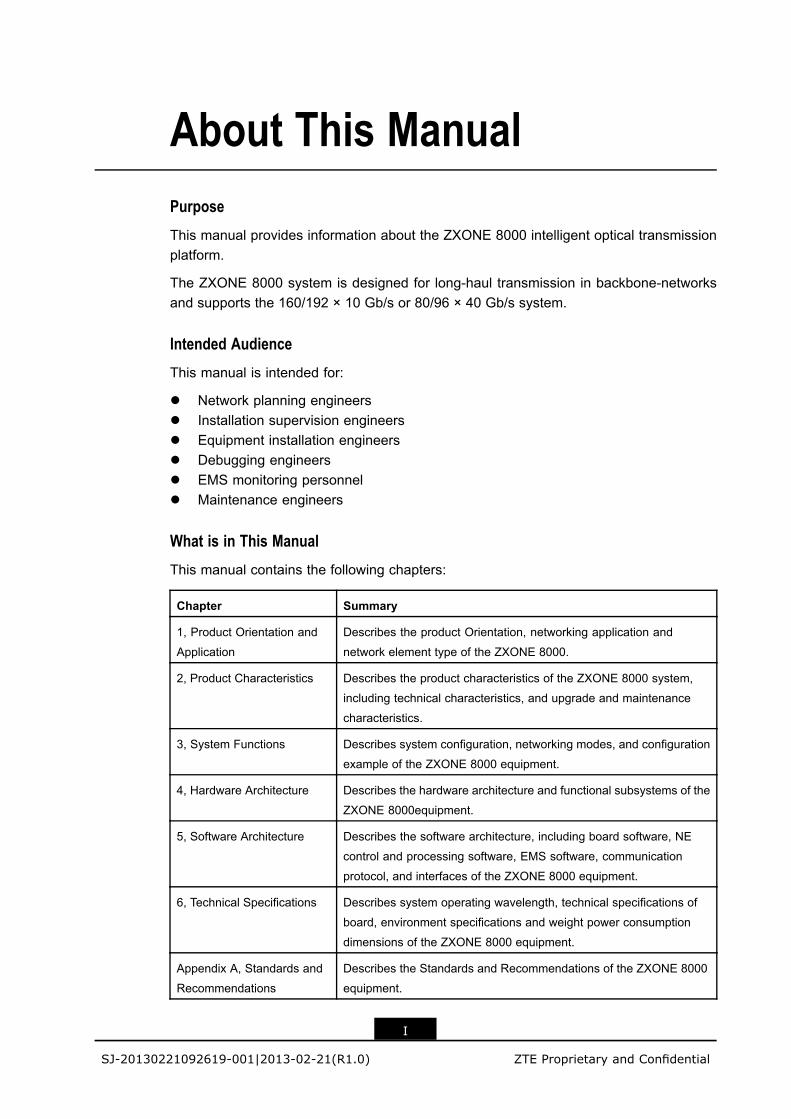
About This ManualPurpose
This manual provides information about the ZXONE 8000 intelligent optical transmissionplatform.
The ZXONE 8000 system is designed for long-haul transmission in backbone-networksand supports the 160/192 × 10 Gb/s or 80/96 × 40 Gb/s system.
Intended Audience
This manual is intended for:
l Network planning engineersl Installation supervision engineersl Equipment installation engineersl Debugging engineersl EMS monitoring personnell Maintenance engineers
What is in This Manual
This manual contains the following chapters:
Chapter Summary
1, Product Orientation and
Application
Describes the product Orientation, networking application and
network element type of the ZXONE 8000.
2, Product Characteristics Describes the product characteristics of the ZXONE 8000 system,
including technical characteristics, and upgrade and maintenance
characteristics.
3, System Functions Describes system configuration, networking modes, and configuration
example of the ZXONE 8000 equipment.
4, Hardware Architecture Describes the hardware architecture and functional subsystems of the
ZXONE 8000equipment.
5, Software Architecture Describes the software architecture, including board software, NE
control and processing software, EMS software, communication
protocol, and interfaces of the ZXONE 8000 equipment.
6, Technical Specifications Describes system operating wavelength, technical specifications of
board, environment specifications and weight power consumption
dimensions of the ZXONE 8000 equipment.
Appendix A, Standards and
Recommendations
Describes the Standards and Recommendations of the ZXONE 8000
equipment.
I
SJ-20130221092619-001|2013-02-21(R1.0) ZTE Proprietary and Confidential

Related Documentation
The following documentation is related to this manual:
l Unitrans ZXONE 8000 (V1.10) Intelligent Optical Transmission Platform HardwareDescription (Volume I)
l Unitrans ZXONE 8000 (V1.10) Intelligent Optical Transmission Platform HardwareDescription (Volume II)
l Unitrans ZXONE 8000 (V1.10) Intelligent Optical Transmission Platform InstallationManual
l Unitrans ZXONE 8000 (V1.10) Intelligent Optical Transmission Platform MaintenanceManual (Volume I) Routine Maintenance
l Unitrans ZXONE 8000 (V1.10) Intelligent Optical Transmission Platform MaintenanceManual (Volume II) Alarm and Performance
l Unitrans ZXONE 8000 (V1.10) Intelligent Optical Transmission Platform MaintenanceManual (Volume III) Troubleshooting
Conventions
This manual uses the following typographical conventions:
Typeface Meaning
Italics Variables in commands. It may also refer to other related manuals and documents.
Bold Menus, menu options, function names, input fields, option button names, check boxes,
drop-down lists, dialog box names, window names, parameters, and commands.
Constant
width
Text that you type, program codes, filenames, directory names, and function names.
[ ] Optional parameters.
{ } Mandatory parameters.
| Separates individual parameters in a series of parameters.
Danger: indicates an imminently hazardous situation. Failure to comply can result in
death or serious injury, equipment damage, or site breakdown.
Warning: indicates a potentially hazardous situation. Failure to comply can result in
serious injury, equipment damage, or interruption of major services.
Caution: indicates a potentially hazardous situation. Failure to comply can result in
moderate injury, equipment damage, or interruption of minor services.
Note: provides additional information about a particular topic.
II
SJ-20130221092619-001|2013-02-21(R1.0) ZTE Proprietary and Confidential
Chapter 1Product Orientation andApplicationTable of ContentsProduct Orientation ....................................................................................................1-1Networking Application ...............................................................................................1-3Network Element Type ...............................................................................................1-5
1.1 Product OrientationThe ZTE OTN/WDM products are widely used in local/MAN backbone networks (includingthe core layer, convergence layer, and access layer), long-distance networks, and trunknetworks. They provide transmission solutions with various capacities, transmissiondistances, and intelligent service applications.
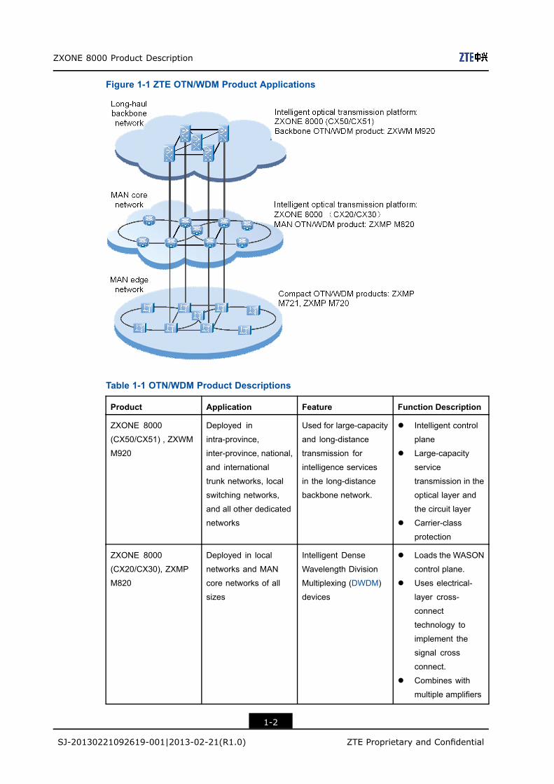
The applications of ZTEOTN/WDMproducts are shown in Figure 1-1. The ZTEOTN/WDMproduct family includes the ZXONE 8000, ZXWM M920, ZXMP M820, ZXMP M721, andZXMP M720.
1-1
SJ-20130221092619-001|2013-02-21(R1.0) ZTE Proprietary and Confidential
ZXONE 8000 Product Description
Figure 1-1 ZTE OTN/WDM Product Applications
Table 1-1 OTN/WDM Product Descriptions
Product Application Feature Function Description
ZXONE 8000
(CX50/CX51) , ZXWM
M920
Deployed in
intra-province,
inter-province, national,
and international
trunk networks, local
switching networks,
and all other dedicated
networks
Used for large-capacity
and long-distance
transmission for
intelligence services
in the long-distance
backbone network.
l Intelligent control
plane
l Large-capacity
service
transmission in the
optical layer and
the circuit layer
l Carrier-class
protection
ZXONE 8000
(CX20/CX30), ZXMP
M820
Deployed in local
networks and MAN
core networks of all
sizes
Intelligent Dense
Wavelength Division
Multiplexing (DWDM)
devices
l Loads the WASON
control plane.
l Uses electrical-
layer cross-
connect
technology to
implement the
signal cross
connect.
l Combines with
multiple amplifiers
1-2
SJ-20130221092619-001|2013-02-21(R1.0) ZTE Proprietary and Confidential
Chapter 1 Product Orientation and Application
Product Application Feature Function Description
such as the
RAMAN amplifier
and large-power
Erbium-Doped
Fiber Amplifier
(EDFA) to extend
transmission
distances of linear
systems.
ZXMP M721, ZXMP
M720
Deployed in
small-capacity
and long-distance
OTN/WDM trunk
networks
Large-capacity,
highly-integrated,
and low-cost
compact OTN/WDM
transmission devices
Used in the core layer,
convergence layer, and
the access layer of
local/MAN networks.
1.2 Networking Application
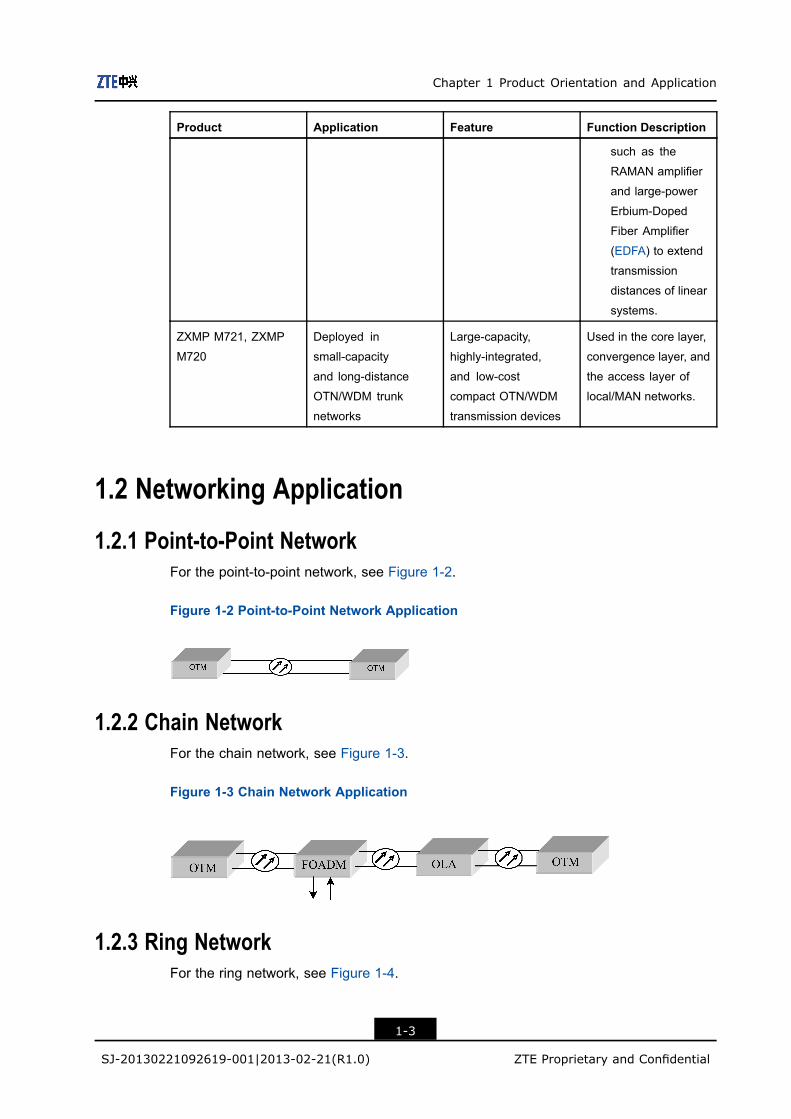
1.2.1 Point-to-Point NetworkFor the point-to-point network, see Figure 1-2.
Figure 1-2 Point-to-Point Network Application
1.2.2 Chain NetworkFor the chain network, see Figure 1-3.
Figure 1-3 Chain Network Application
1.2.3 Ring NetworkFor the ring network, see Figure 1-4.
1-3
SJ-20130221092619-001|2013-02-21(R1.0) ZTE Proprietary and Confidential
ZXONE 8000 Product Description
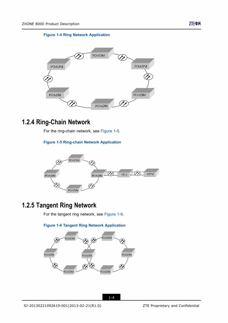
Figure 1-4 Ring Network Application
1.2.4 Ring-Chain NetworkFor the ring-chain network, see Figure 1-5.
Figure 1-5 Ring-chain Network Application
1.2.5 Tangent Ring NetworkFor the tangent ring network, see Figure 1-6.
Figure 1-6 Tangent Ring Network Application
1-4
SJ-20130221092619-001|2013-02-21(R1.0) ZTE Proprietary and Confidential
Chapter 1 Product Orientation and Application
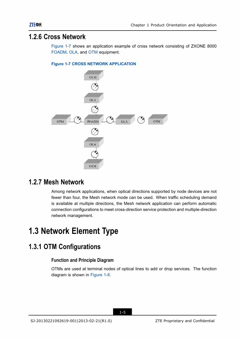
1.2.6 Cross NetworkFigure 1-7 shows an application example of cross network consisting of ZXONE 8000FOADM, OLA, and OTM equipment.
Figure 1-7 CROSS NETWORK APPLICATION
1.2.7 Mesh NetworkAmong network applications, when optical directions supported by node devices are notfewer than four, the Mesh network mode can be used. When traffic scheduling demandis available at multiple directions, the Mesh network application can perform automaticconnection configurations to meet cross-direction service protection and multiple-directionnetwork management.
1.3 Network Element Type
1.3.1 OTM Configurations
Function and Principle Diagram
OTMs are used at terminal nodes of optical lines to add or drop services. The functiondiagram is shown in Figure 1-8.
1-5
SJ-20130221092619-001|2013-02-21(R1.0) ZTE Proprietary and Confidential

ZXONE 8000 Product Description
Figure 1-8 OTM Equipment Operating Principle Diagram
Board Configurations
OTM configurations are described as follows by taking a 96–channel system as anexample.
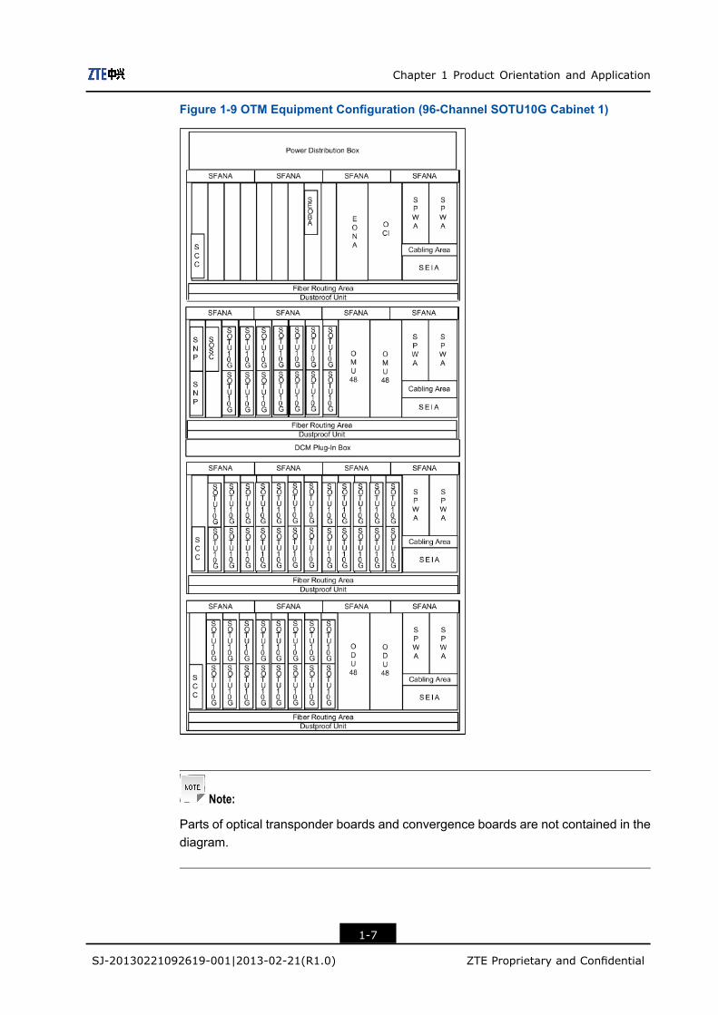
l If SOTU10G boards are used, the OTM equipment is configured with six subracksand two cabinets. For the subracks and boards configurations, see Figure 1-9 andFigure 1-10.
1-6
SJ-20130221092619-001|2013-02-21(R1.0) ZTE Proprietary and Confidential
Chapter 1 Product Orientation and Application
Figure 1-9 OTM Equipment Configuration (96-Channel SOTU10G Cabinet 1)
Note:
Parts of optical transponder boards and convergence boards are not contained in thediagram.
1-7
SJ-20130221092619-001|2013-02-21(R1.0) ZTE Proprietary and Confidential
ZXONE 8000 Product Description
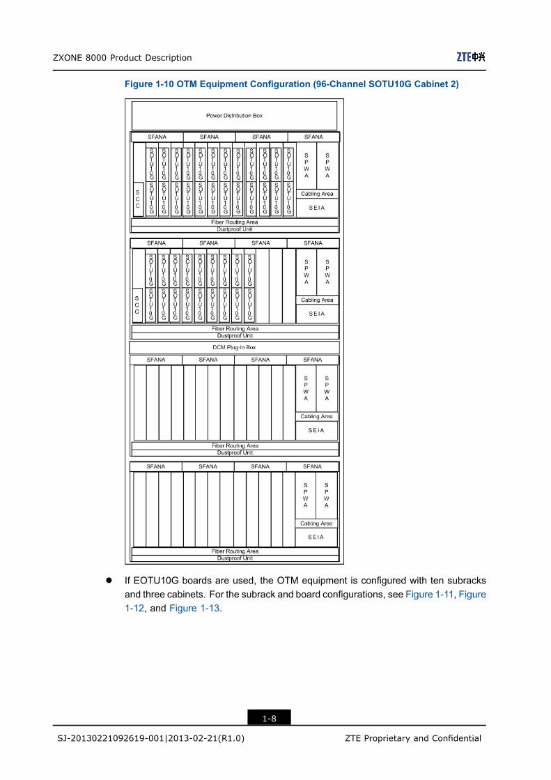
Figure 1-10 OTM Equipment Configuration (96-Channel SOTU10G Cabinet 2)
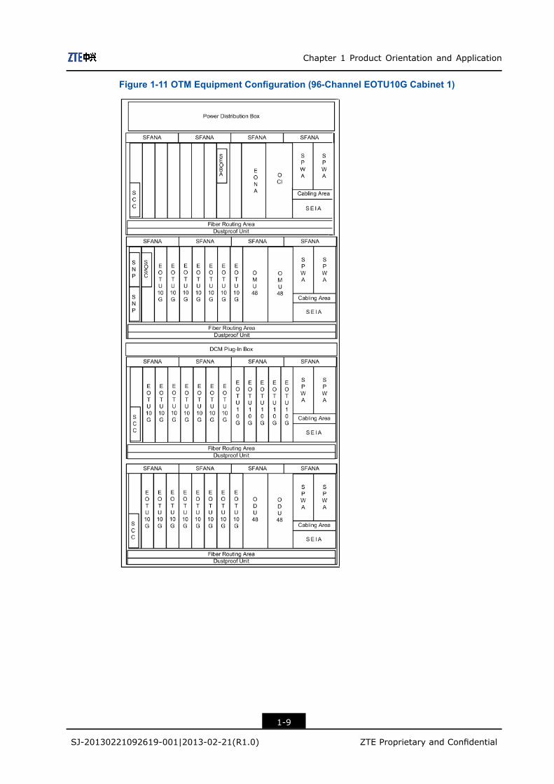
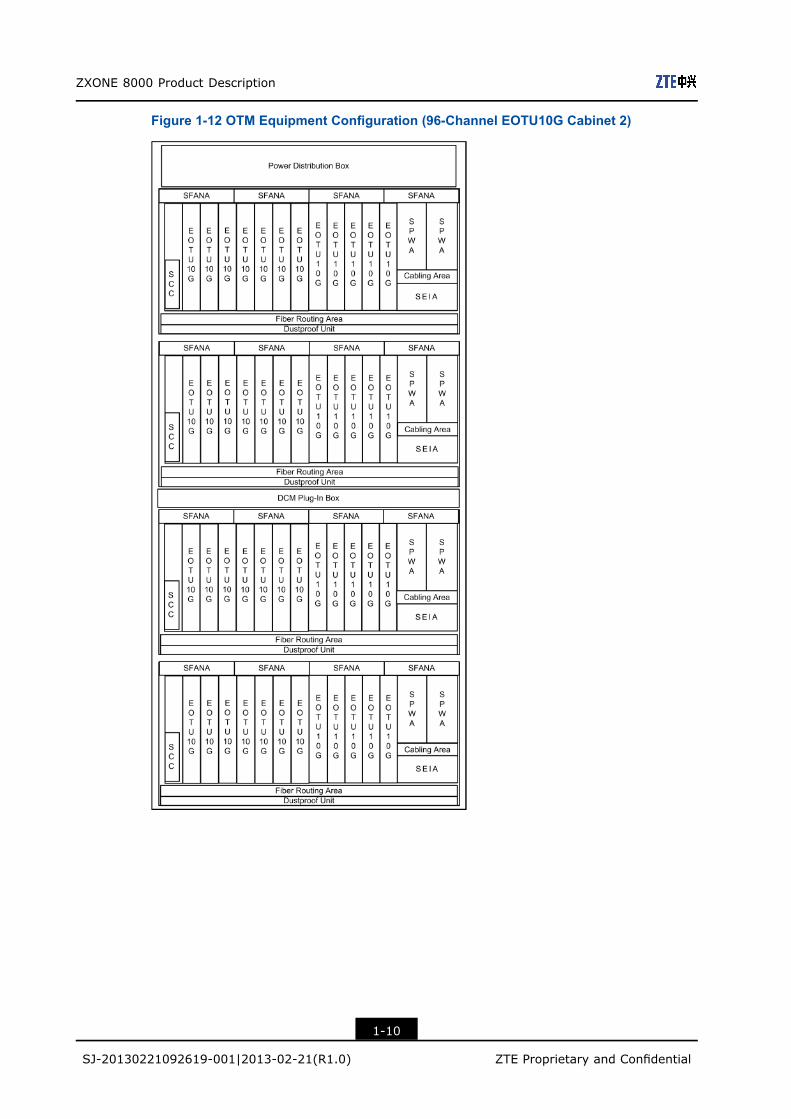
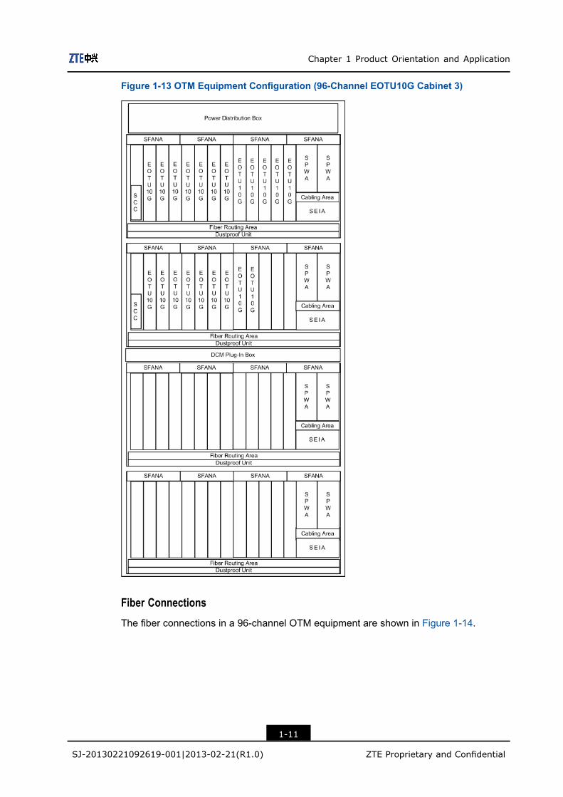
l If EOTU10G boards are used, the OTM equipment is configured with ten subracksand three cabinets. For the subrack and board configurations, see Figure 1-11, Figure1-12, and Figure 1-13.
1-8
SJ-20130221092619-001|2013-02-21(R1.0) ZTE Proprietary and Confidential
Chapter 1 Product Orientation and Application
Figure 1-11 OTM Equipment Configuration (96-Channel EOTU10G Cabinet 1)
1-9
SJ-20130221092619-001|2013-02-21(R1.0) ZTE Proprietary and Confidential
ZXONE 8000 Product Description
Figure 1-12 OTM Equipment Configuration (96-Channel EOTU10G Cabinet 2)
1-10
SJ-20130221092619-001|2013-02-21(R1.0) ZTE Proprietary and Confidential
Chapter 1 Product Orientation and Application
Figure 1-13 OTM Equipment Configuration (96-Channel EOTU10G Cabinet 3)
Fiber Connections
The fiber connections in a 96-channel OTM equipment are shown in Figure 1-14.
1-11
SJ-20130221092619-001|2013-02-21(R1.0) ZTE Proprietary and Confidential

ZXONE 8000 Product Description
Figure 1-14 Optical Connections in OTM Equipment (96-Channel)
Configuration Description
For the configuration description of the OTM equipment, refer to Table 1-2.
Table 1-2 Configuration Description
Configuration Requirements Description
To implement the
multiplexing/demultiplexing
of channels,
Each OMU/ODU board occupies 4 slots.
To implement the optical
amplification,
Each EONA board occupies 4 slots
Each SEOBA board occupies 1 slot.
The EOBAH board can be used to replace the SEOBA board to
meet the requirements for high output power.
The EOBAH board occupies 4 slots.
For the 8/16/32/40/48 channel
system,
when SEOBA or SEOPA boards are not configured, the
SSDM board can be used for the multplexing/demultiplexing of
1550/1510 nm wavelengths.
For the 80/96/160/176/192
channel system,
the OCI board and OBM board are used in the 80/96/160/176/192
channel system.
the 80-channel system can also use OMU80/ODU80 boards to
implement wavelength multiplexing/demulitplexing.
1-12
SJ-20130221092619-001|2013-02-21(R1.0) ZTE Proprietary and Confidential
Chapter 1 Product Orientation and Application
Configuration Requirements Description
To implement the OCH/OMS 1+1
protection,
if the OCH/OMS 1+1 protection is required, the SOP boards
should be configured. The configuration positions of SOP boards
and optical fiber connections should be determined according
to the protection types.
To implement the OCH 1:N
protection,
if the OCH 1:N protection is required, OMCP boards should be
configured between the user equipment and OTU boards.
For the dispersion compensation
after a long-haul transmission,
the DCM plug-in boxes and DCM modules should be configured
according to the fiber types and the requirements.
To implement the aggregation, any OTU (SOTU10G/EOTU10G) board displayed in Figure
1-14 can be replaced by the aggregate board (SRM41, SRM42,
DSAC, DSAF, FCA, MQT3 or SMUB board).
1.3.2 FOADM Configurations
Function and Principle Diagram
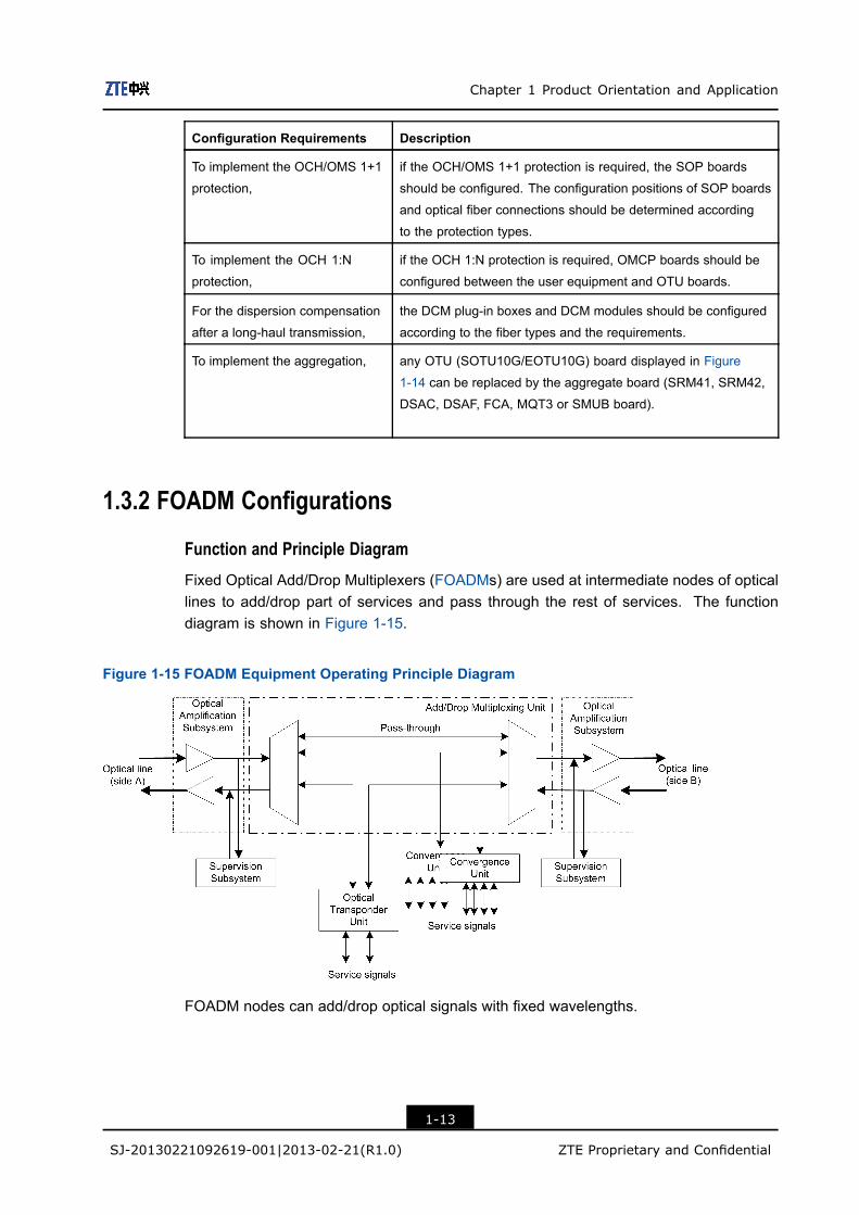
Fixed Optical Add/Drop Multiplexers (FOADMs) are used at intermediate nodes of opticallines to add/drop part of services and pass through the rest of services. The functiondiagram is shown in Figure 1-15.
Figure 1-15 FOADM Equipment Operating Principle Diagram
FOADM nodes can add/drop optical signals with fixed wavelengths.
1-13
SJ-20130221092619-001|2013-02-21(R1.0) ZTE Proprietary and Confidential
ZXONE 8000 Product Description
Cabinet and Subrack Configurations
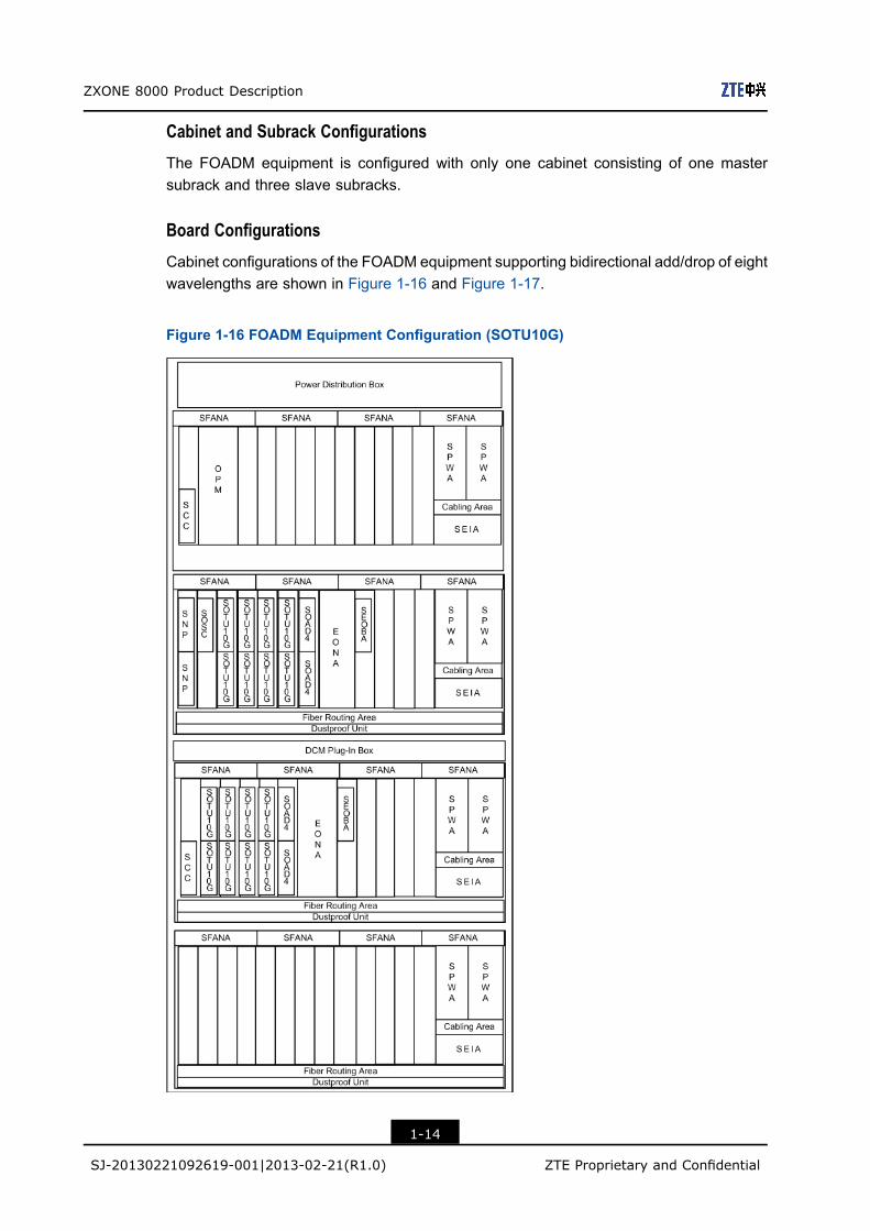
The FOADM equipment is configured with only one cabinet consisting of one mastersubrack and three slave subracks.
Board Configurations
Cabinet configurations of the FOADM equipment supporting bidirectional add/drop of eightwavelengths are shown in Figure 1-16 and Figure 1-17.
Figure 1-16 FOADM Equipment Configuration (SOTU10G)
1-14
SJ-20130221092619-001|2013-02-21(R1.0) ZTE Proprietary and Confidential

Chapter 1 Product Orientation and Application
Figure 1-17 FOADM Equipment Configuration (EOTU10G)
Fiber Connections
Fiber connections in the FOADM equipment supporting unidirectional add/drop of eightwavelengths are shown in Figure 1-18.
1-15
SJ-20130221092619-001|2013-02-21(R1.0) ZTE Proprietary and Confidential

ZXONE 8000 Product Description
Figure 1-18 FOADM Equipment Fiber Connections (Unidirectional Add/Drop of EightWavelengths)
SOGMD boards can also be used in the FOADM equipment to implement themultiplexing/demultiplexing of a group of wavelengths. The fiber connections are shownin Figure 1-19.
Figure 1-19 FOADM Equipment Fiber Connections (Configured with SOGMD Boards)
1-16
SJ-20130221092619-001|2013-02-21(R1.0) ZTE Proprietary and Confidential
Chapter 1 Product Orientation and Application
Configuration DescriptionFor the configuration description of the FOADM equipment, see Table 1-3.
Table 1-3 Configuration Description
Configuration Requirements Description
Required Boards Each SOAD board occupies one slot, and supports the
transmission/receipt of optical signals in only one direction, that
is, both IN and OUT interfaces of an SOAD board are connected
to the same site.
To add/drop more wavelengths, each SOAD board can add/drop fixed one to four wavelength
signals. If the add/drop function is required for more wavelengths,
SOAD boards and OMU/ODU boards are needed to be
cascaded.
To implement the OCH/OMS
1+1 protection or electrical-layer
service board redundancy 1+1
protection,
the SOP boards should be installed, and positions and optical
connections of the SOP boards should be determined according
to the protection mode.
To implement the OCH 1:N
protection,
OMCP boards should be added between user equipment and
optical transponder boards.
To implement the OMS or OCH
ring protection,
the SOPMS or SOPCS boards should be added, and fiber
connection relations should be determined according to the
protection mode.
For the dispersion compensation
after long-distance transmissions
DCM plug-in boxes should be installed, and dispersion
compensation modules should be configure d as required.
To implement the aggregation, an OTU board shown in Figure 1-19 should be replaced with an
aggregate board (SRM41, SRM42, DSAC or SAUC board).
1.3.3 ROADM Configurations
Equipment FeaturesThe ROADM equipment supports the following features:l Wavelength reconstruction in two directions and in multiple directions.l Adding/dropping local wavelengths: adding/dropping local fixed wavelengths,
adding/dropping any local wavelength at any port, and adding/dropping/broadcastingany direction-irrelevant wavelength.
Cabinet, Subrack and Board ConfigurationThe ROADM equipment is configured with only one cabinet consisting of one mastersubrack and three slave subracks.
Boards: WBU/WBM/WSU/PDU
1-17
SJ-20130221092619-001|2013-02-21(R1.0) ZTE Proprietary and Confidential
ZXONE 8000 Product Description
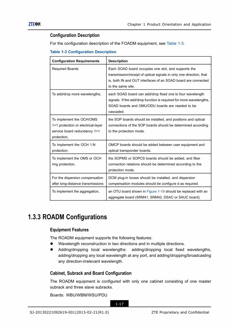
Fiber Connections
Figure 1-20 illustrates a two-dimension fiber connections diagram of the ROADMequipment configured with WBM.
Figure 1-20 Fiber Connections in ROADM Equipment (Configured with WBM Boards)
Figure 1-21 illustrates a two-dimension fiber connections diagram of the ROADMequipment configured with WBU.
Figure 1-21 Fiber Connections in ROADM Equipment (Configured with WBU Boards)
1-18
SJ-20130221092619-001|2013-02-21(R1.0) ZTE Proprietary and Confidential
Chapter 1 Product Orientation and Application
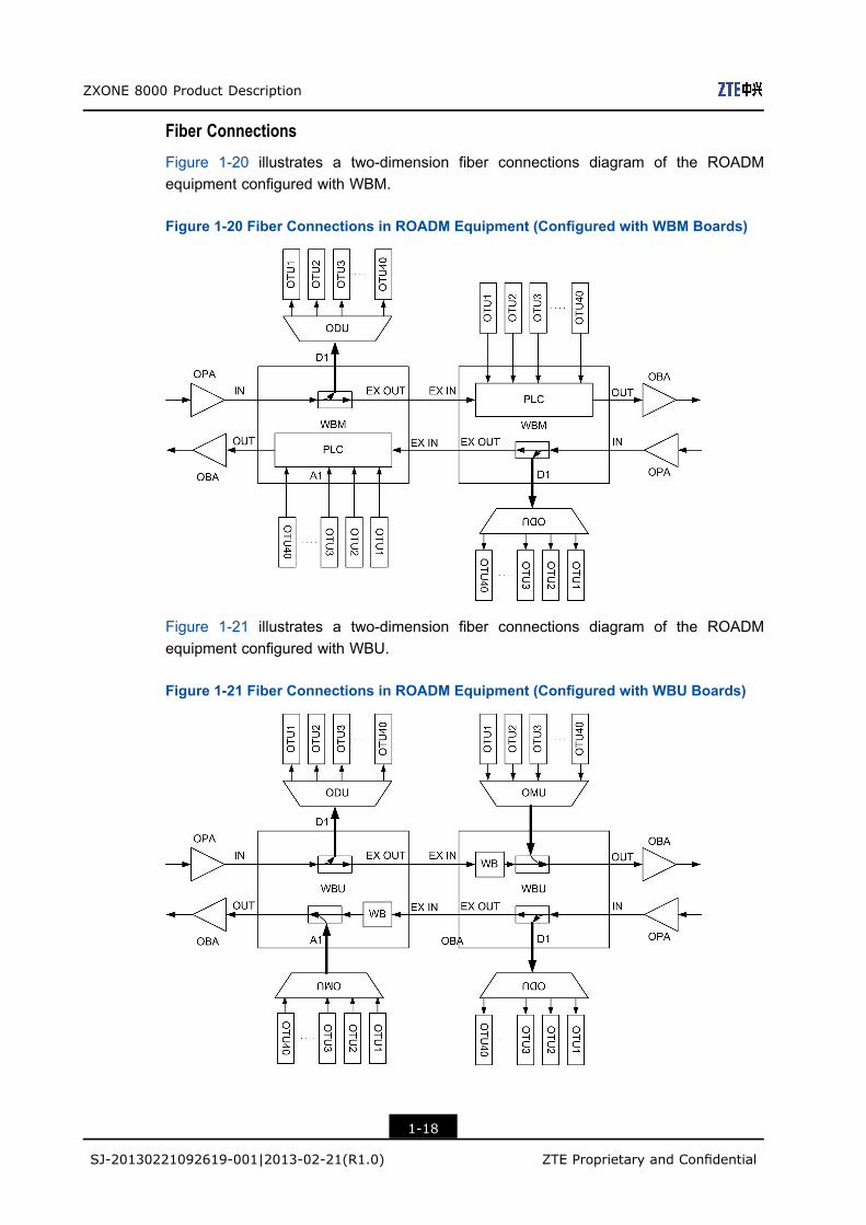
Figure 1-22 illustrates a two-dimension fiber connections diagram of the ROADMequipment configured with WSU.
Figure 1-22 Fiber Connections in ROADM Equipment (Configured with WSU Boards)
Figure 1-23 illustrates a three-dimension fiber connections diagram of the ROADMequipment.
Figure 1-23 Fiber Connections in ROADM Equipment (Three Dimensions)
Figure 1-24 illustrates a nine-dimension fiber connections diagram of the ROADMequipment.
1-19
SJ-20130221092619-001|2013-02-21(R1.0) ZTE Proprietary and Confidential

ZXONE 8000 Product Description
Figure 1-24 Fiber Connections in ROADM Equipment (Nine Dimensions)
Configuration Description
1. Each SEOBA board occupies one slot. Each EONA board occupies four slots. EachWBU/WSU/WBM board occupies four slots.
2. If OCH/OMS 1+1 protection or electrical-layer service board redundancy 1+1 protec-tion is required, SOP boards should be added, and positions and optical connectionsof the SOP boards should be determined according to the protection mode.
3. If OCH 1:N protection is required, OMCP boards should be added between userequipment and optical transponder boards.
4. If OMS or OCH ring protection is required, SOPMSor SOPCS boards should be added,and fiber connection relations should be determined according to the protection mode.
5. If dispersion compensation is required for the OADM equipment after long-haultransmissions, DCM plug-in boxes should be added, and dispersion compensationmodules should be configured as required.
6. If the SOGMD board is configured in network, the black wavelengths in SOGMDboards cannot be occupied.
7. When the ROADM equipment is configured, if only the add/drop function is required,WBU boards should be configured, drop wavelengths should be fixed, and each WBUboard should be configured on direction A and B.
8. When the ROADM equipment is configured, if the add/drop function as well as portconfiguration are required, WSUD boards should be configured.
1-20
SJ-20130221092619-001|2013-02-21(R1.0) ZTE Proprietary and Confidential

Chapter 1 Product Orientation and Application
9. When the ROADMequipment is configured, if the add/drop function, port configuration,and service broadcast are required, WSUA boards should be configured.
10. When the ROADM equipment is configured, if the add function and pass-throughfunction are required, WBM boards should be configured.
11. When the ROADM equipment is configured, if couplers are required for the powerisolation, PDU boards should be configured.
ROADM Network Relevances
For the direction/wavelength correlations, refer to Table 1-4.
Table 1-4 Direction/Wavelength Correlation
Item Description
Direction relevance Services in add channels on the local node cannot be sent to any
direction.
Direction irrelevance Services in add channels on the local node can be sent to any
direction.
Wavelength relevance Services cannot be sent to an OTU-type board through any drop
channel on the local node.
Wavelength irrelevance Services can be sent to an OTU-type board through any drop
channel on the local node.
ROADM Network Relevance Implementation Schemes
l For the implementation of direction relevance and wavelength relevance, see Figure1-25.
1-21
SJ-20130221092619-001|2013-02-21(R1.0) ZTE Proprietary and Confidential

ZXONE 8000 Product Description
Figure 1-25 Direction Relevance and Wavelength Relevance
l For the implementation of direction irrelevance and wavelength relevance, see Figure1-26.
1-22
SJ-20130221092619-001|2013-02-21(R1.0) ZTE Proprietary and Confidential

Chapter 1 Product Orientation and Application
Figure 1-26 Direction Irrelevance and Wavelength Relevance
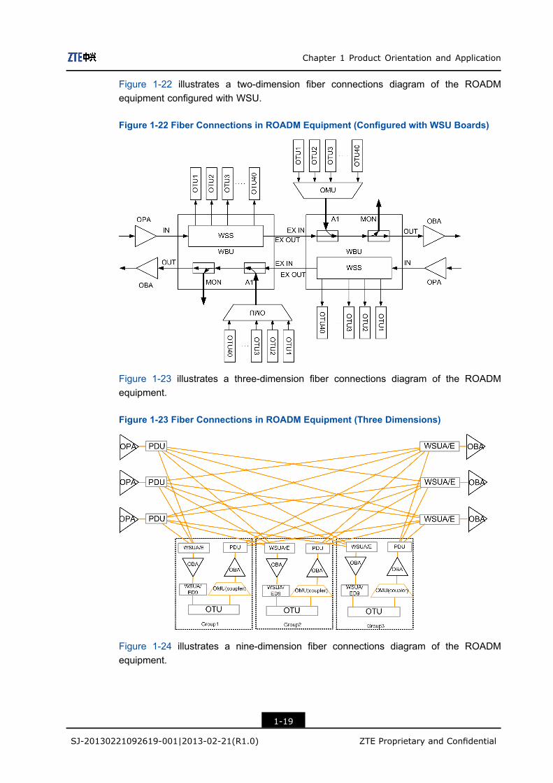
l For the implementation of direction irrelevance and wavelength irrelevance, seeFigure 1-27.
1-23
SJ-20130221092619-001|2013-02-21(R1.0) ZTE Proprietary and Confidential
ZXONE 8000 Product Description
Figure 1-27 Direction Irrelevance and Wavelength Irrelevance
l For the implementation of direction relevance and wavelength irrelevance, see Figure1-28.
1-24
SJ-20130221092619-001|2013-02-21(R1.0) ZTE Proprietary and Confidential
Chapter 1 Product Orientation and Application
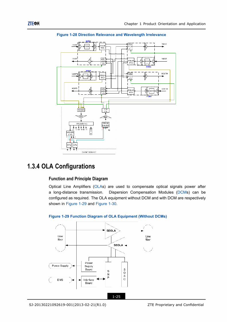
Figure 1-28 Direction Relevance and Wavelength Irrelevance
1.3.4 OLA Configurations
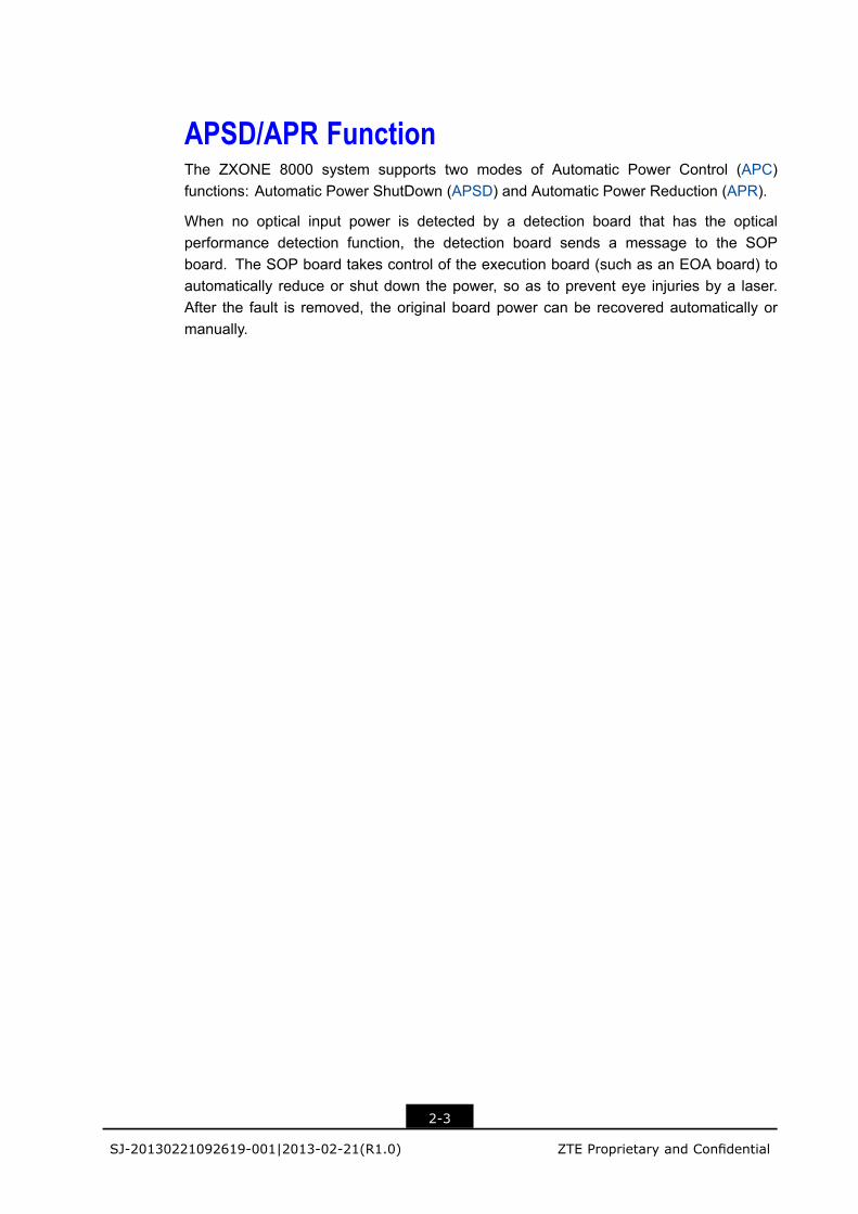
Function and Principle DiagramOptical Line Amplifiers (OLAs) are used to compensate optical signals power aftera long-distance transmission. Dispersion Compensation Modules (DCMs) can beconfigured as required. The OLA equipment without DCM and with DCM are respectivelyshown in Figure 1-29 and Figure 1-30.
Figure 1-29 Function Diagram of OLA Equipment (Without DCMs)
1-25
SJ-20130221092619-001|2013-02-21(R1.0) ZTE Proprietary and Confidential

ZXONE 8000 Product Description
Figure 1-30 Function Diagram of OLA Equipment (With DCMs)
Board Configurations
Board configurations of the OLA equipment with single-channel rate are described asfollows:
l The single-channel rate is 2.5 Gbit/s.
The OLA equipment with single-channel rate at 2.5 Gbit/s is shown in Figure 1-31.
Figure 1-31 OLA Equipment Configuration (2.5 Gbit/s)
l The single-channel rate is 10 Gbit/s.
EOLA equipments at 10Gbit/s always combine EONA boards and DCMs to implementthe amplification and dispersion compensation of optical signals. The OLA equipmentwith single-channel rate at 10 Gbit/s is shown in Figure 1-32.
1-26
SJ-20130221092619-001|2013-02-21(R1.0) ZTE Proprietary and Confidential

Chapter 1 Product Orientation and Application
Figure 1-32 OLA Equipment Configuration (10 Gbit/s)
Fiber Connections
l Fiber connections in the OLA equipment at 2.5 Gbit/s are shown in Figure 1-33.
Figure 1-33 OLA Equipment Fiber Connections (2.5 Gbit/s)
l Fiber connections in the OLA equipment at 10 Gbit/s are shown in Figure 1-34.
Figure 1-34 OLA Equipment Fiber Connection (10 Gbit/s)
Configuration Description
For the OLA equipment configuration description, refer to Table 1-5.
1-27
SJ-20130221092619-001|2013-02-21(R1.0) ZTE Proprietary and Confidential

ZXONE 8000 Product Description
Table 1-5 Configuration Description
ConfigurationRequirements
Description
Required Boards Each EONA board occupies four slots.
The EOLAD board can serve as EOLA board
When the transmission rate
is 10 Gbit/s or 40 Gbit/s,
DCMs are used to implement dispersion compensation. DCMs should
be selected according to the fiber type and the actual distance that
needs dispersion compensation.
For the 160/176–channel
system,
1. The main optical path should be divided into C (or CE) band and L
band through a C/L filter.
2. The C (or CE)-band EDFA and L-band EDFA should be used for
amplification.
3. All the optical signals are combined into one channel through
C/L-band broadband multiplexers.
It is necessary to add OBM boards before and after the main optical
path.
1-28
SJ-20130221092619-001|2013-02-21(R1.0) ZTE Proprietary and Confidential

Chapter 2Product CharacteristicsTable of Contents
Technology Characteristics.........................................................................................2-1Upgrade and Maintenance Characteristics ...............................................................2-10
2.1 Technology Characteristics
2-1
SJ-20130221092619-001|2013-02-21(R1.0) ZTE Proprietary and Confidential

FEC and AFEC FunctionsThe ZXONE 8000 system uses Forward Error Correction (FEC) technology, which has thefollowing advantages:
l Improves the error-tolerance capability of transmitted signalsl Reduces the system requirement on the signal-to-noise ratiol Extends the transmission distance
There are two types of FEC functions: Ordinary FEC and Advanced FEC (AFEC), refer toTable 2-1.
Table 2-1 Ordinary FEC and AFEC
FEC Type Ordinary FEC AFEC
Frame structure G.709 G.975
STM-64 10.709 Gbit/s 10.709 Gbit/s
10 GE 11.1 Gbit/s 11.1 Gbit/s
Traffic rate
2.5 G 2.66 Gbit/s Unavailable
OSNR 5 dB to 6 dB 7 dB to 9 dB
2-2
SJ-20130221092619-001|2013-02-21(R1.0) ZTE Proprietary and Confidential
APSD/APR FunctionThe ZXONE 8000 system supports two modes of Automatic Power Control (APC)functions: Automatic Power ShutDown (APSD) and Automatic Power Reduction (APR).
When no optical input power is detected by a detection board that has the opticalperformance detection function, the detection board sends a message to the SOPboard. The SOP board takes control of the execution board (such as an EOA board) toautomatically reduce or shut down the power, so as to prevent eye injuries by a laser.After the fault is removed, the original board power can be recovered automatically ormanually.
2-3
SJ-20130221092619-001|2013-02-21(R1.0) ZTE Proprietary and Confidential
Erbium-Doped Fiber Amplifier (EDFA)The ZXONE 8000 system uses EDFA technology to improve the transmission distance. Itprovides the following benefits:
l Greatly reduces the cost of optical regeneration.l High gain, low noise, large bandwidth, high output power, high pump efficiency, low
insertion loss, and insensitivity for polarization.
2-4
SJ-20130221092619-001|2013-02-21(R1.0) ZTE Proprietary and Confidential
Distributed RAMAN AmplificationIn the Optical Transport Network (OTN)/Wavelength-Division Multiplexing (WDM) systemwith ultra-long-haul transmission distances, using only the EDFA technology to implementthe amplification accumulates spontaneous radiation and restricts the performance ofthe system. The ZXONE 8000 system uses a Distributed RAMAN Amplification (DRA)board to effectively improve the optical-amplification performance of the ultra-long-haultransmission system through the combination of EDFA and DRA technologies (thecombination of EOA board and DRA board).
2-5
SJ-20130221092619-001|2013-02-21(R1.0) ZTE Proprietary and Confidential

Intelligent ROADMThe ZXONE 8000 system provides an intelligent Reconfigurable Optical Add/DropMultiplexer (ROADM). An intelligent ROADM is composed of a Power Distribution Unit(PDU) and a Wavelength Selective Switch Unit (WSU). The intelligent ROADM improvesthe flexibility of the WDM network. Thus, the operator can remotely and dynamicallycontrol the wavelength transmission path, and effectively reduce the operation andmaintenance costs. The detailed functions provided by intelligent ROADM are as follows:
l Provides add/drop of local optical signals.l Supports service broadcast.l Supports wavelength scheduling from up to nine optical directions.l Supports any combinations between wavelength-relevance (wavelength-related,
wavelength-unrelated) and direction-relevance (direction-related,direction-unrelated), including:
à wavelength-related, direction-related;
à wavelength-related, direction-unrelated;
à wavelength-unrelated, direction-related;
à wavelength-unrelated, direction-unrelated.
2-6
SJ-20130221092619-001|2013-02-21(R1.0) ZTE Proprietary and Confidential
Performance Monitoring Functionl The ZXONE 8000 system provides an optical performance monitoring unit. This unit
is responsible for measuring parameters of each optical channel, including the opticalpower, central wavelength and Optical Signal-Noise Ratio (OSNR), and sending thesedata to the EMS, in which users can view the performance data in a list or in a graph.
l The optical transponder unit supports performance monitoring and overheadprocessing function. It can locate the faults and fault types according to the followingaccess signals:
à For OTN signals: detects performance and alarm messages, including LossOf Frame (LOF) alarm, Bit Interleaved Parity (BIP-8), the overhead Trail TraceIdentifier (TTI), corrected bit error count, uncorrectable frame count, OTUk-AIS,ODUk-AIS, ODUk-OCI, ODUk-LCK, PM-BIP8, ODUk-PT.
à For SDH signals: monitors RS_BBE(B1) and J0 bytes.
à For GE signals: monitors the packet error count, packet error ratio, and GenericFraming Procedure (GFP) performance.
l The boards on the main optical path use the power collection and monitoringtechnology with great dynamic range and high accuracy. With the technology, thepower measurement error is less than 1 dB and the system performance can be trulyreflected.
2-7
SJ-20130221092619-001|2013-02-21(R1.0) ZTE Proprietary and Confidential
Electrical Cross Connect FunctionThe electrical cross connect function of ZXONE 8000 system is divided into centralizedelectrical cross connect and distributed electrical cross connect.
Centralized Electrical Cross Connect
By using a cross connect board and the backplane together, the centralized electrical crossconnect function implements the flexible time-slot cross connect scheduling of time-slotframes on the backplane. After the scheduling, one or one group of time-slot frames aredemultiplexed on the service board to restore the service. The centralized electrical crossconnect system is based on synchronous time division scheduling, which is applicable tolarge-scale scheduling systems. The centralized electrical cross connect system has thefollowing features:
l The cross connect capacities are 0.8 TB, 1.6 TB, and 3.2 TB.l The cross connect granularities are ODU0, ODU1, ODU2 and ODU3.l Access services can be cross-connected to different wavelengths and directions.l This function supports the access of any service ranging from 100M to 1.25G,
including FE/GE/10GE/40GE/100GE, STM-1/STM-4/STM-16/STM-64/STM-256,FC400/800, FC200/FC400/FC800, and ODUk (where k = 0/1/2/2e/3/3e1/3e2)services.
l As an unblocked network, the cross connect network supports broadcasting andtransparent transmission of Ethernet clock.
Distributed Electrical Cross Connect
By using a backplane, the distributed electrical cross connect function implements crossconnect scheduling of frames. After the scheduling, the frame is demultiplexed on theservice board in the distributed cross connect group to restore the service. The distributedelectrical cross connect system has the following features:
l A single subrack can be configured with at most six distributed cross connect groups.The cross connect capacity and the access capacity of each group are 80 GB.
l The cross connect granularity is ODU0/ODU1/oDU2.l This function implements access of the service at rates of 100 Mbit/s to 4.25 Gbit/s
through board combinations.
2-8
SJ-20130221092619-001|2013-02-21(R1.0) ZTE Proprietary and Confidential
RPOA TechnologyThe ZXONE 8000 system uses the Remotely Pumped Optical Amplifier (RPOA)technology, which is an ultra-long-distance transmission technology.
In the RPOA system, a segment of Erbium-Doped Fiber (EDF) is inserted in transmissionoptical cables, which provides pumped light at a far-end site to amplify optical signals.
The RPOA system was developed to implement ultra-long, single-span transmission whenno power supply is available in the system.
It usually applies in the following cases:
l No power supply is available, or regenerator sites cannot be established when opticalcables cross over straits or adjacent seas, or pass through depopulated areas (suchas deserts, marshes and forests).
l The construction and maintenance of regenerator sites is difficult in remote areas dueto territorial limits.
RPOA supports the following applications:
l Unidirectional pump application through the same fiberl Unidirectional pump application through different fibersl Bidirectional pump application through two fibers
2-9
SJ-20130221092619-001|2013-02-21(R1.0) ZTE Proprietary and Confidential
ZXONE 8000 Product Description
2.2 Upgrade and Maintenance CharacteristicsMaster and Slave Subracks
The ZXONE 8000 system supports the master/slave subrack installation.
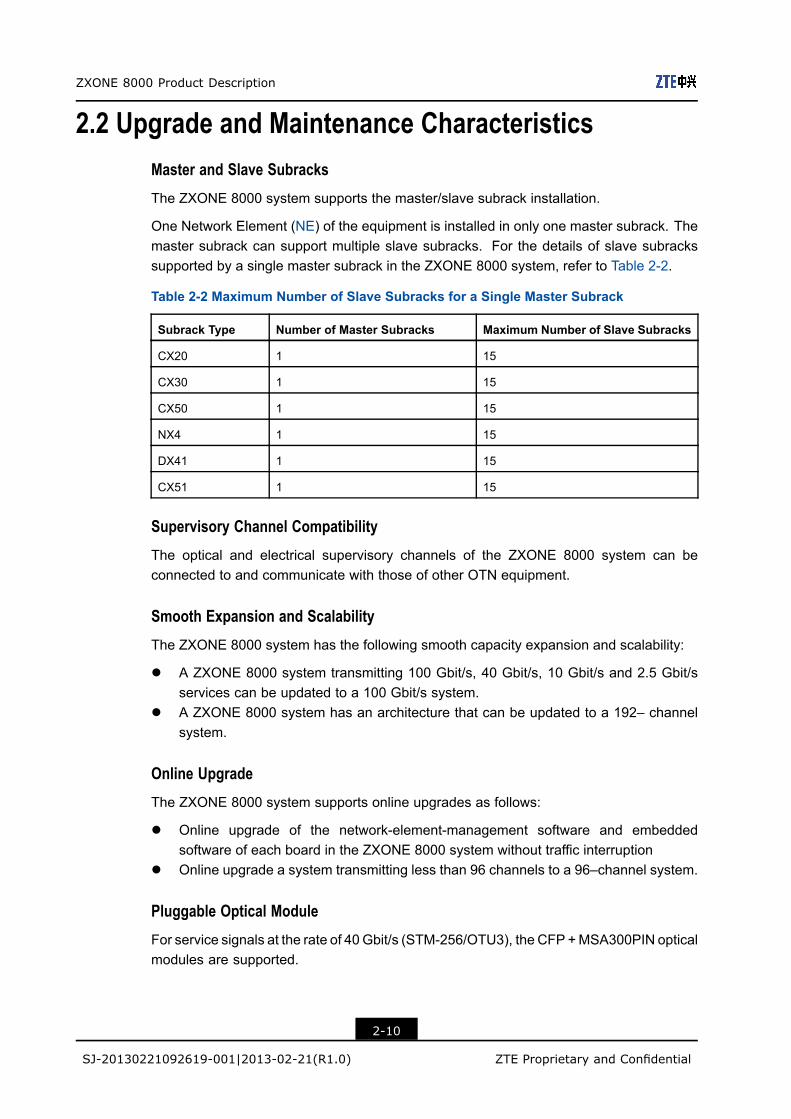
One Network Element (NE) of the equipment is installed in only one master subrack. Themaster subrack can support multiple slave subracks. For the details of slave subrackssupported by a single master subrack in the ZXONE 8000 system, refer to Table 2-2.
Table 2-2 Maximum Number of Slave Subracks for a Single Master Subrack
Subrack Type Number of Master Subracks Maximum Number of Slave Subracks
CX20 1 15
CX30 1 15
CX50 1 15
NX4 1 15
DX41 1 15
CX51 1 15
Supervisory Channel Compatibility
The optical and electrical supervisory channels of the ZXONE 8000 system can beconnected to and communicate with those of other OTN equipment.
Smooth Expansion and Scalability
The ZXONE 8000 system has the following smooth capacity expansion and scalability:
l A ZXONE 8000 system transmitting 100 Gbit/s, 40 Gbit/s, 10 Gbit/s and 2.5 Gbit/sservices can be updated to a 100 Gbit/s system.
l A ZXONE 8000 system has an architecture that can be updated to a 192– channelsystem.
Online Upgrade
The ZXONE 8000 system supports online upgrades as follows:
l Online upgrade of the network-element-management software and embeddedsoftware of each board in the ZXONE 8000 system without traffic interruption
l Online upgrade a system transmitting less than 96 channels to a 96–channel system.
Pluggable Optical Module
For service signals at the rate of 40Gbit/s (STM-256/OTU3), the CFP +MSA300PIN opticalmodules are supported.
2-10
SJ-20130221092619-001|2013-02-21(R1.0) ZTE Proprietary and Confidential
Chapter 2 Product Characteristics
For service signals at the rate of 10 Gbit/s (STM-64/OC-192/10GE/OTU2), 10–GigabitSmall Form-Fator Pluggable optical modules (XFP) and SFP+ optical modules aresupported.
For service signals with the rate of 2.5 Gbit/s or below, the optical interfaces at the clientside support Small Form-Factor Pluggable optical modules (SFP).
Pluggable-optical modules support the position-detection for optical modules.
2-11
SJ-20130221092619-001|2013-02-21(R1.0) ZTE Proprietary and Confidential
ZXONE 8000 Product Description
This page intentionally left blank.
2-12
SJ-20130221092619-001|2013-02-21(R1.0) ZTE Proprietary and Confidential
Chapter 3System FunctionsTable of Contents
Line Transmission Function........................................................................................3-1Automatic Power Optimization Function .....................................................................3-5IWF Function..............................................................................................................3-6Wavelength Tunable Function ....................................................................................3-6Chromatic Dispersion Compensation..........................................................................3-7Service Functions.......................................................................................................3-7Communication and Supervision Function..................................................................3-9Alarm Monitoring Function........................................................................................3-11Protection Functions.................................................................................................3-12Clock Management Function ....................................................................................3-19Clock Synchronization Function ...............................................................................3-19
3.1 Line Transmission Function
3.1.1 Transmission Capacity
Wavelength Capacity
The ZXONE 8000 system can be configured as a transmission system with a maximumof 192 channels. The wavelength capacity of each channel can reach a maximum of 100Gbit/s.
Channel Rate
The ZXONE 8000 system supports single-channel rates at 100 Gbit/s, 40 Gbit/s, 10 Gbit/s,and 2.5 Gbit/s.
Channel Spacings
The ZXONE 8000 system uses the Dense Wavelength Division Multiplexing (DWDM)technology. It supports channel spacings of 50 GHz and 100 GHz.
3.1.2 Channel RateThe ZXONE 8000 system supports single-channel rates at 100 Gbit/s, 40 Gbit/s, 10 Gbit/s,and 2.5 Gbit/s.
3-1
SJ-20130221092619-001|2013-02-21(R1.0) ZTE Proprietary and Confidential
ZXONE 8000 Product Description
3.1.3 Channel SpacingsThe ZXONE 8000 system uses the Dense Wavelength Division Multiplexing (DWDM)technology. It supports channel spacings of 50 GHz and 100 GHz.
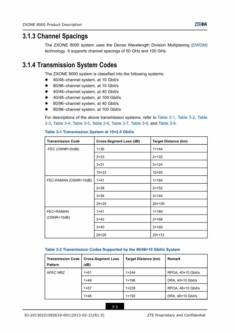
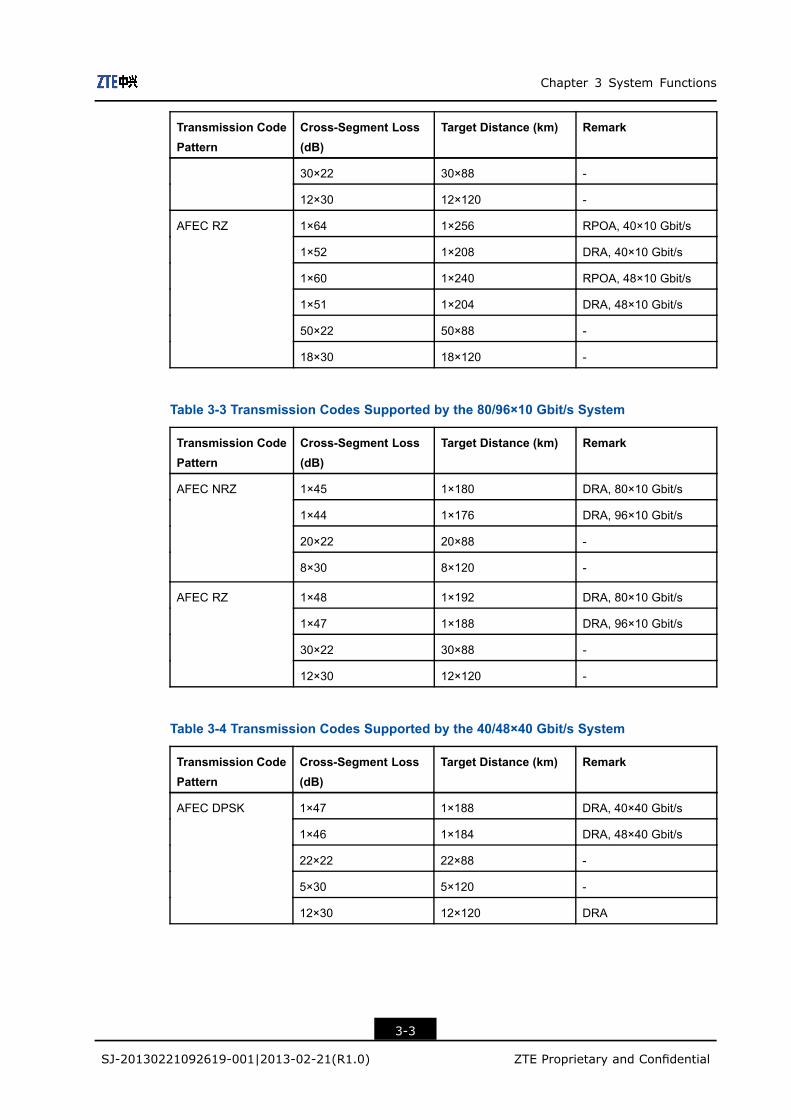
3.1.4 Transmission System CodesThe ZXONE 8000 system is classified into the following systems:l 40/48–channel system, at 10 Gbit/sl 80/96–channel system, at 10 Gbit/sl 40/48–channel system, at 40 Gbit/sl 40/48–channel system, at 100 Gbit/sl 80/96–channel system, at 40 Gbit/sl 80/96–channel system, at 100 Gbit/s
For descriptions of the above transmission systems, refer to Table 3-1, Table 3-2, Table3-3, Table 3-4, Table 3-5, Table 3-6, Table 3-7, Table 3-8, and Table 3-9.
Table 3-1 Transmission System at 10×2.5 Gbit/s
Transmission Code Cross-Segment Loss (dB) Target Distance (km)
1×36 1×144
2×33 2×132
3×31 3×124
-FEC (OSNR>20dB)
10×23 10×92
1×41 1×164
2×38 2×152
3×36 3×144
FEC-RAMAN (OSNR>15dB)
20×25 20×100
1×41 1×180
2×42 2×168
3×40 3×160
FEC+RAMAN
(OSNR>15dB)
20×28 20×112
Table 3-2 Transmission Codes Supported by the 40/48×10 Gbit/s System
Transmission CodePattern
Cross-Segment Loss(dB)
Target Distance (km) Remark
1×61 1×244 RPOA, 40×10 Gbit/s
1×49 1×196 DRA, 40×10 Gbit/s
1×57 1×228 RPOA, 48×10 Gbit/s
1×48 1×192 DRA, 48×10 Gbit/s
AFEC NRZ
3-2
SJ-20130221092619-001|2013-02-21(R1.0) ZTE Proprietary and Confidential
Chapter 3 System Functions
Transmission CodePattern
Cross-Segment Loss(dB)
Target Distance (km) Remark
30×22 30×88 -
12×30 12×120 -
1×64 1×256 RPOA, 40×10 Gbit/s
1×52 1×208 DRA, 40×10 Gbit/s
1×60 1×240 RPOA, 48×10 Gbit/s
1×51 1×204 DRA, 48×10 Gbit/s
50×22 50×88 -
AFEC RZ
18×30 18×120 -
Table 3-3 Transmission Codes Supported by the 80/96×10 Gbit/s System
Transmission CodePattern
Cross-Segment Loss(dB)
Target Distance (km) Remark
1×45 1×180 DRA, 80×10 Gbit/s
1×44 1×176 DRA, 96×10 Gbit/s
20×22 20×88 -
AFEC NRZ
8×30 8×120 -
1×48 1×192 DRA, 80×10 Gbit/s
1×47 1×188 DRA, 96×10 Gbit/s
30×22 30×88 -
AFEC RZ
12×30 12×120 -
Table 3-4 Transmission Codes Supported by the 40/48×40 Gbit/s System
Transmission CodePattern
Cross-Segment Loss(dB)
Target Distance (km) Remark
1×47 1×188 DRA, 40×40 Gbit/s
1×46 1×184 DRA, 48×40 Gbit/s
22×22 22×88 -
5×30 5×120 -
AFEC DPSK
12×30 12×120 DRA
3-3
SJ-20130221092619-001|2013-02-21(R1.0) ZTE Proprietary and Confidential
ZXONE 8000 Product Description
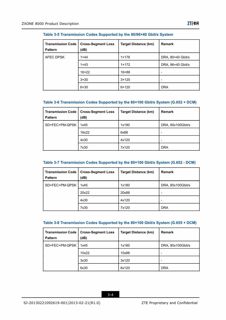
Table 3-5 Transmission Codes Supported by the 80/96×40 Gbit/s System
Transmission CodePattern
Cross-Segment Loss(dB)
Target Distance (km) Remark
1×44 1×176 DRA, 80×40 Gbit/s
1×43 1×172 DRA, 96×40 Gbit/s
16×22 16×88 -
3×30 3×120 -
AFEC DPSK
6×30 6×120 DRA
Table 3-6 Transmission Codes Supported by the 80×100 Gbit/s System (G.652 + DCM)
Transmission CodePattern
Cross-Segment Loss(dB)
Target Distance (km) Remark
1x45 1x180 DRA, 80x100Gbit/s
16x22 6x88 -
4x30 4x120 -
SD+FEC+PM-QPSK
7x30 7x120 DRA
Table 3-7 Transmission Codes Supported by the 80×100 Gbit/s System (G.652 - DCM)
Transmission CodePattern
Cross-Segment Loss(dB)
Target Distance (km) Remark
1x45 1x180 DRA, 80x100Gbit/s
20x22 20x88 -
4x30 4x120 -
SD+FEC+PM-QPSK
7x30 7x120 DRA
Table 3-8 Transmission Codes Supported by the 80×100 Gbit/s System (G.655 + DCM)
Transmission CodePattern
Cross-Segment Loss(dB)
Target Distance (km) Remark
1x45 1x180 DRA, 80x100Gbit/s
10x22 10x88 -
3x30 3x120 -
SD+FEC+PM-QPSK
6x30 6x120 DRA
3-4
SJ-20130221092619-001|2013-02-21(R1.0) ZTE Proprietary and Confidential
Chapter 3 System Functions
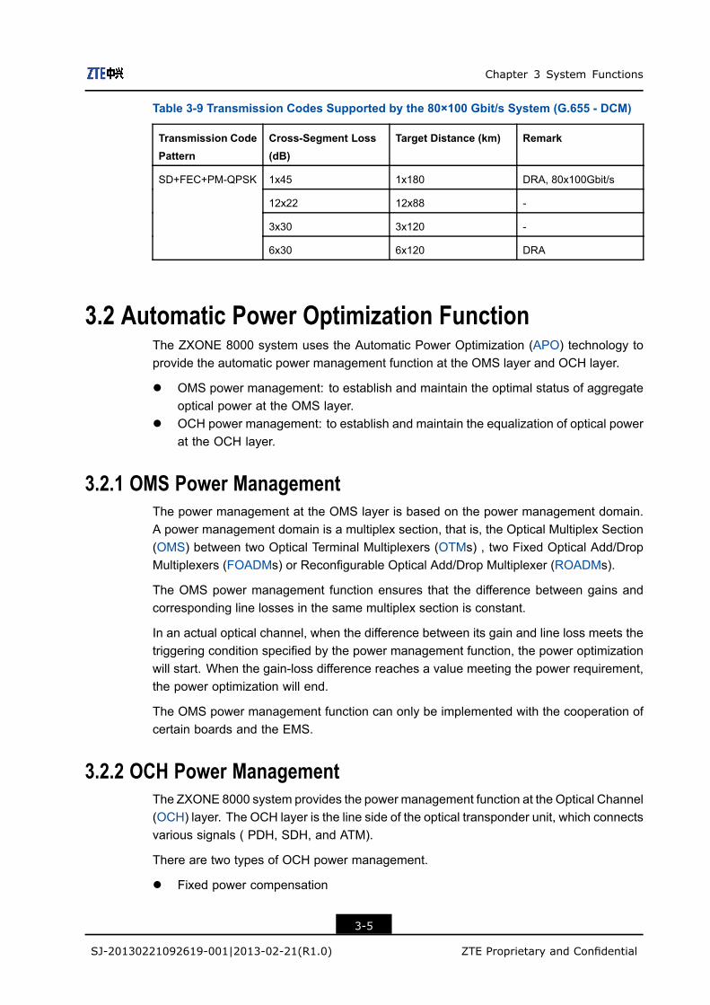
Table 3-9 Transmission Codes Supported by the 80×100 Gbit/s System (G.655 - DCM)
Transmission CodePattern
Cross-Segment Loss(dB)
Target Distance (km) Remark
1x45 1x180 DRA, 80x100Gbit/s
12x22 12x88 -
3x30 3x120 -
SD+FEC+PM-QPSK
6x30 6x120 DRA
3.2 Automatic Power Optimization FunctionThe ZXONE 8000 system uses the Automatic Power Optimization (APO) technology toprovide the automatic power management function at the OMS layer and OCH layer.
l OMS power management: to establish and maintain the optimal status of aggregateoptical power at the OMS layer.
l OCH power management: to establish and maintain the equalization of optical powerat the OCH layer.
3.2.1 OMS Power ManagementThe power management at the OMS layer is based on the power management domain.A power management domain is a multiplex section, that is, the Optical Multiplex Section(OMS) between two Optical Terminal Multiplexers (OTMs) , two Fixed Optical Add/DropMultiplexers (FOADMs) or Reconfigurable Optical Add/Drop Multiplexer (ROADMs).
The OMS power management function ensures that the difference between gains andcorresponding line losses in the same multiplex section is constant.
In an actual optical channel, when the difference between its gain and line loss meets thetriggering condition specified by the power management function, the power optimizationwill start. When the gain-loss difference reaches a value meeting the power requirement,the power optimization will end.
The OMS power management function can only be implemented with the cooperation ofcertain boards and the EMS.
3.2.2 OCH Power ManagementThe ZXONE 8000 system provides the power management function at the Optical Channel(OCH) layer. The OCH layer is the line side of the optical transponder unit, which connectsvarious signals ( PDH, SDH, and ATM).
There are two types of OCH power management.
l Fixed power compensation
3-5
SJ-20130221092619-001|2013-02-21(R1.0) ZTE Proprietary and Confidential

ZXONE 8000 Product Description
A fixed equalization filter in an Erbium-Doped Fiber Amplifier (EDFA) is used to ensurethe flatness of gain spectrum.
l Dynamic channel power management
Dynamic gain equalization technology and power pre-equalization technology areused to adjust the optical power of each channel to guarantee the optical powerequalization of each channel at the optical receiving end.
3.3 IWF FunctionThe frequency drift has little impact on a DWDM system with channel spacing at 100GHz. But it has an impact on a DWDM system reliability with higher channel rate andless channel spacing, such as an 80/96 channel system with channel spacing at 50 GHz.
The ZXONE 8000 system provides two modes to ensure the system reliability.
l The systemwith 100GHz channel spacing uses automatic power control, temperaturefeedback, and internal wavelength feedback, which are implemented by opticaltransponder boards.
l The system with 50 GHz channel spacing uses internal wavelength feedback andexternal wavelength feedback, which improves stability and accuracy of wavelengthcontrol.
à Internal wavelength feedback: It is implemented by optical transponder boards.
à External wavelength feedback: It is implemented by the Integrated WavelengthFeedback (IWF) function. The IWF function uses integrated detection andordered adjustment to implement the wavelength feedback control. OWMboards, OMU boards, OTU boards, SNP boards, and EMS work together toimplement the IWF function.
3.4 Wavelength Tunable FunctionTraditional DWDM systems use fixed wavelength lasers as light sources, which onlyoutput fixed wavelengths complying with ITU-T G.694.1 recommendation. Fixedwavelength lasers cannot be fully utilized when they are used as standby light sources,which causes the operation costs. The development of light source technology uses atunable wavelength laser to meet the requirements for multi-wavelength tuning.
The tunable wavelength laser refers to a laser module that can be controlled to outputdifferent wavelengths in a certain bandwidth. The channel quantity and channel spacingof the output wavelengths meet the specifications of ITU-T G.694.1. With the applicationof tunable wavelength lasers, wavelengths can be selected dynamically for signals in aDWDM system according to the actual application of wavelengths. Especially when thesystem uses standby light sources, using tunable wavelength lasers can improve theutilization ratio of wavelengths.
Some service boards of the ZXONE 8000system support both fixed wavelength outputand tunable wavelength output. Table 3-10 lists the boards supporting wavelength tuning
3-6
SJ-20130221092619-001|2013-02-21(R1.0) ZTE Proprietary and Confidential
Chapter 3 System Functions
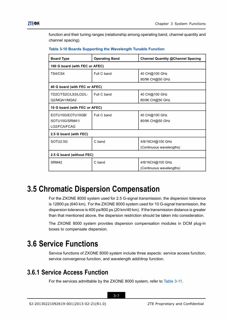
function and their tuning ranges (relationship among operating band, channel quantity andchannel spacing).
Table 3-10 Boards Supporting the Wavelength Tunable Function
Board Type Operating Band Channel Quantity @Channel Spacing
100 G board (with FEC or AFEC)
TS4/CS4 Full C band 40 CH@100 GHz
80/96 CH@50 GHz
40 G board (with FEC or AFEC)
TD2C/TS2C/LS3/LO2/L-
Q2/MQA1/MQA2
Full C band 40 CH@100 GHz
80/96 CH@50 GHz
10 G board (with FEC or AFEC)
EOTU10G/EOTU10GB/
SOTU10G/SRM41/
LO2/FCA/FCAG
Full C band 40 CH@100 GHz
80/96 CH@50 GHz
2.5 G board (with FEC)
SOTU2.5G C band 4/8/16CH@100 GHz
(Continuous wavelengths)
2.5 G board (without FEC)
SRM42 C band 4/8/16CH@100 GHz
(Continuous wavelengths)
3.5 Chromatic Dispersion CompensationFor the ZXONE 8000 system used for 2.5 G-signal transmission, the dispersion toleranceis 12800 ps (640 km). For the ZXONE 8000 system used for 10 G-signal transmission, thedispersion tolerance is 400 ps/800 ps (20 km/40 km). If the transmission distance is greaterthan that mentioned above, the dispersion restriction should be taken into consideration.
The ZXONE 8000 system provides dispersion compensation modules in DCM plug-inboxes to compensate dispersion.
3.6 Service FunctionsService functions of ZXONE 8000 system include three aspects: service access function,service convergence function, and wavelength add/drop function.
3.6.1 Service Access FunctionFor the services admittable by the ZXONE 8000 system, refer to Table 3-11.
3-7
SJ-20130221092619-001|2013-02-21(R1.0) ZTE Proprietary and Confidential
ZXONE 8000 Product Description
Table 3-11 Services Admittable by the ZXONE 8000 System
Service Description
Synchronous Digital Hierarchy (SDH)
services
STM-1, STM-4, STM-16, STM-64, STM-256, OTU3,
OTU3u, OTU3e, and OTU3f
Plesiochronous Digital Hierarchy
(PDH) Services
E3 and E4
Synchronous Optical Network (SONET
services
OC-3, OC-12, OC-48, OC-192, and OC-768
Asynchronous Transfer Mode (ATM
services or Packet Over SONET/SDH
(POS) services
VC4, VC4-4c, and VC4-16c
Ethernet services FE, GE, 10GE, 40GE, 100GE
SAN services ESCON, FICON, FC1/2/4/8, 2GFC, 4GFC, 10GFC
Other services Digital Video Broadcasting (DVB), FDDI, Fiber Connection
(FICON), High Definition Television (HDTV), and Enterprise
System Connection (ESCON)
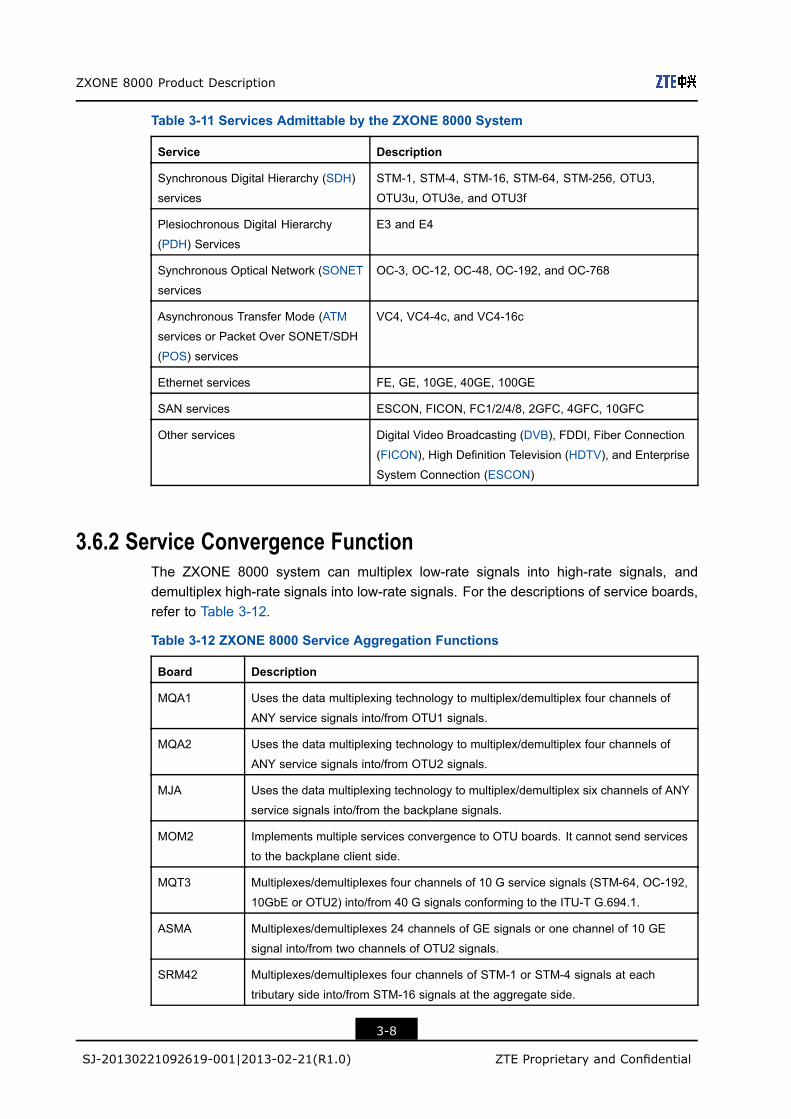
3.6.2 Service Convergence FunctionThe ZXONE 8000 system can multiplex low-rate signals into high-rate signals, anddemultiplex high-rate signals into low-rate signals. For the descriptions of service boards,refer to Table 3-12.
Table 3-12 ZXONE 8000 Service Aggregation Functions
Board Description
MQA1 Uses the data multiplexing technology to multiplex/demultiplex four channels of
ANY service signals into/from OTU1 signals.
MQA2 Uses the data multiplexing technology to multiplex/demultiplex four channels of
ANY service signals into/from OTU2 signals.
MJA Uses the data multiplexing technology to multiplex/demultiplex six channels of ANY
service signals into/from the backplane signals.
MOM2 Implements multiple services convergence to OTU boards. It cannot send services
to the backplane client side.
MQT3 Multiplexes/demultiplexes four channels of 10 G service signals (STM-64, OC-192,
10GbE or OTU2) into/from 40 G signals conforming to the ITU-T G.694.1.
ASMA Multiplexes/demultiplexes 24 channels of GE signals or one channel of 10 GE
signal into/from two channels of OTU2 signals.
SRM42 Multiplexes/demultiplexes four channels of STM-1 or STM-4 signals at each
tributary side into/from STM-16 signals at the aggregate side.
3-8
SJ-20130221092619-001|2013-02-21(R1.0) ZTE Proprietary and Confidential

Chapter 3 System Functions
Board Description
SRM41 Multiplexes/demultiplexes four channels of STM-16 signals at each tributary
side into/from STM-64 signals at the aggregate side. It supports SDH
synchronous convergence or OTN asynchronous convergence and FEC/AFEC
encoding/decoding. In addition, it complies with the ITU-T G.709.
FCA Multiplexes/demultiplexes two channels of 4G FC, four channels of 2G FC, or eight
channels of FC signals into/from OTU2 signals.
3.7 Communication and Supervision Function
3.7.1 Supervisory ChannelsThe monitoring subsystem of the ZXONE 8000 system consists of SNP, CCP, SOSCBand SEIA1/SEIA2 boards. The monitoring system contains Optical Supervisory Channel(OSC) and Electric Supervisory Channel (ESC) to transmit the EMS and orderwireinformation.
l For the descriptions of optical supervisory channels, refer to Table 3-13.
Table 3-13 ZXONE 8000 Optical Supervisory Channel
Item Capability
Monitoring rate 100 Mbit/s
Monitoring direction à The monitoring system supports 16 monitoring directions by in-
stalling four SOSCB boards, which can satisfy the monitoring
direction requirements.
à Each SOSCB board supports monitoring on four directions. Multiple
SOSCB boards can be installed to support more monitoring direc-
tions.
à When SOSCB boards serve for optical monitoring, slot 3 or slot 5 in
subrack 1 must be installed with an SOSCB board.
Compatibility The 100 M optical supervisory channels of the ZXONE 8000 system
can communicate with the 100 M optical supervisory channels of the
ZXMP M820 system and ZXWM M920 system.
l For descriptions of electrical supervisory channels, refer to Table 3-14.
3-9
SJ-20130221092619-001|2013-02-21(R1.0) ZTE Proprietary and Confidential
ZXONE 8000 Product Description
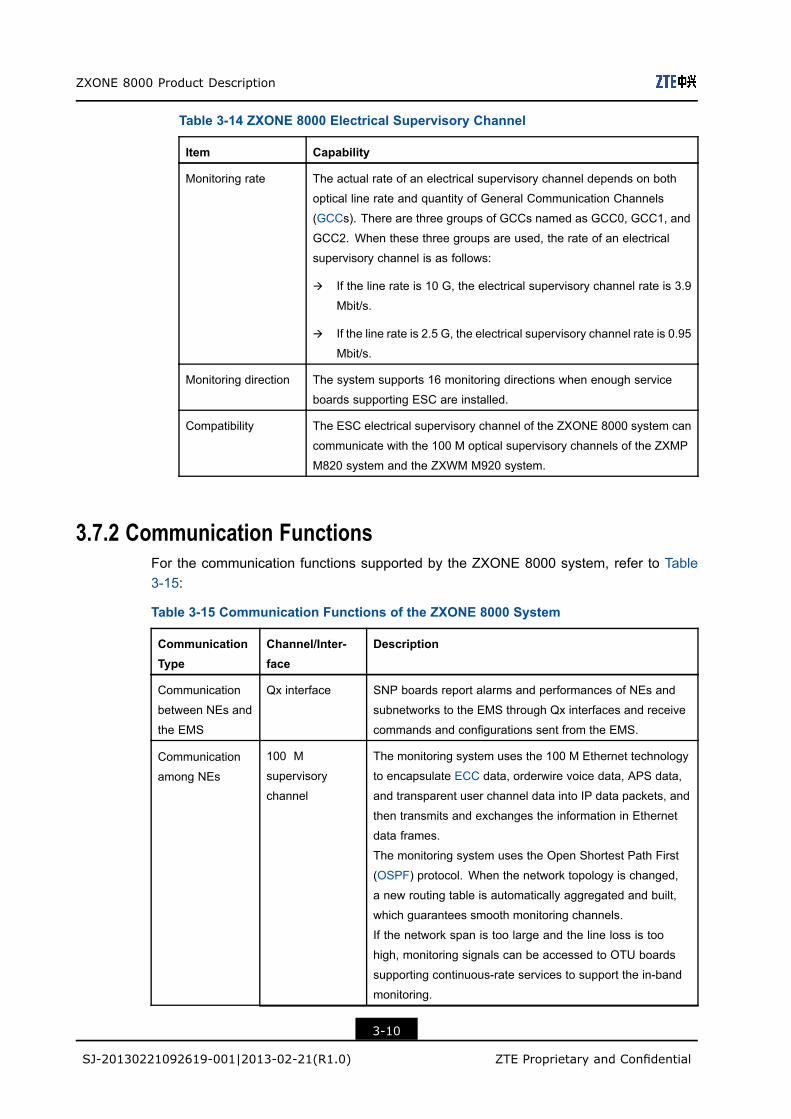
Table 3-14 ZXONE 8000 Electrical Supervisory Channel
Item Capability
Monitoring rate The actual rate of an electrical supervisory channel depends on both
optical line rate and quantity of General Communication Channels
(GCCs). There are three groups of GCCs named as GCC0, GCC1, and
GCC2. When these three groups are used, the rate of an electrical
supervisory channel is as follows:
à If the line rate is 10 G, the electrical supervisory channel rate is 3.9
Mbit/s.
à If the line rate is 2.5 G, the electrical supervisory channel rate is 0.95
Mbit/s.
Monitoring direction The system supports 16 monitoring directions when enough service
boards supporting ESC are installed.
Compatibility The ESC electrical supervisory channel of the ZXONE 8000 system can
communicate with the 100 M optical supervisory channels of the ZXMP
M820 system and the ZXWM M920 system.
3.7.2 Communication FunctionsFor the communication functions supported by the ZXONE 8000 system, refer to Table3-15:
Table 3-15 Communication Functions of the ZXONE 8000 System
CommunicationType
Channel/Inter-face
Description
Communication
between NEs and
the EMS
Qx interface SNP boards report alarms and performances of NEs and
subnetworks to the EMS through Qx interfaces and receive
commands and configurations sent from the EMS.
100 M
supervisory
channel
The monitoring system uses the 100 M Ethernet technology
to encapsulate ECC data, orderwire voice data, APS data,
and transparent user channel data into IP data packets, and
then transmits and exchanges the information in Ethernet
data frames.
The monitoring system uses the Open Shortest Path First
(OSPF) protocol. When the network topology is changed,
a new routing table is automatically aggregated and built,
which guarantees smooth monitoring channels.
If the network span is too large and the line loss is too
high, monitoring signals can be accessed to OTU boards
supporting continuous-rate services to support the in-band
monitoring.
Communication
among NEs
3-10
SJ-20130221092619-001|2013-02-21(R1.0) ZTE Proprietary and Confidential
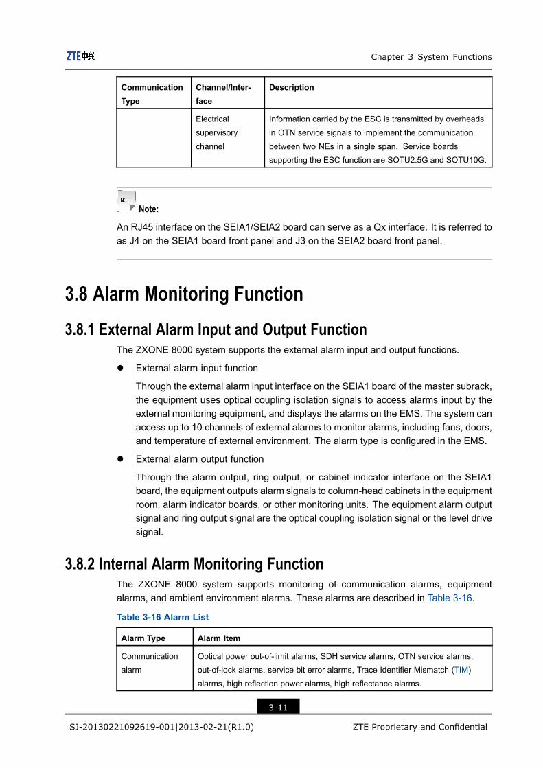
Chapter 3 System Functions
CommunicationType
Channel/Inter-face
Description
Electrical
supervisory
channel
Information carried by the ESC is transmitted by overheads
in OTN service signals to implement the communication
between two NEs in a single span. Service boards
supporting the ESC function are SOTU2.5G and SOTU10G.
Note:
An RJ45 interface on the SEIA1/SEIA2 board can serve as a Qx interface. It is referred toas J4 on the SEIA1 board front panel and J3 on the SEIA2 board front panel.
3.8 Alarm Monitoring Function
3.8.1 External Alarm Input and Output FunctionThe ZXONE 8000 system supports the external alarm input and output functions.
l External alarm input function
Through the external alarm input interface on the SEIA1 board of the master subrack,the equipment uses optical coupling isolation signals to access alarms input by theexternal monitoring equipment, and displays the alarms on the EMS. The system canaccess up to 10 channels of external alarms to monitor alarms, including fans, doors,and temperature of external environment. The alarm type is configured in the EMS.
l External alarm output function
Through the alarm output, ring output, or cabinet indicator interface on the SEIA1board, the equipment outputs alarm signals to column-head cabinets in the equipmentroom, alarm indicator boards, or other monitoring units. The equipment alarm outputsignal and ring output signal are the optical coupling isolation signal or the level drivesignal.
3.8.2 Internal Alarm Monitoring FunctionThe ZXONE 8000 system supports monitoring of communication alarms, equipmentalarms, and ambient environment alarms. These alarms are described in Table 3-16.
Table 3-16 Alarm List
Alarm Type Alarm Item
Communication
alarm
Optical power out-of-limit alarms, SDH service alarms, OTN service alarms,
out-of-lock alarms, service bit error alarms, Trace Identifier Mismatch (TIM)
alarms, high reflection power alarms, high reflectance alarms.
3-11
SJ-20130221092619-001|2013-02-21(R1.0) ZTE Proprietary and Confidential

ZXONE 8000 Product Description
Alarm Type Alarm Item
Equipment alarm l Temperature-related alarms
Temperature out-of-limit alarm of lasers, boards and modules.
l Current-related alarms
Over-current alarm of lasers and cooler, laser bias current out-of-limit alarm,
pump laser bias over-current alarm.
l Board-related alarms
Laser/pump life alarm, laser fault alarm, M-Z modulator bias voltage
out-of-limit alarm, module failure alarm, module communication fault
alarm, DSP operation alarm, high pump reflection power alarm, high pump
reflectance alarm, laser failure alarm, board out-of-position alarm, board
mounting alarm, and fan fault alarm.
Ambient
environment alarm
Fire alarm, temperature alarm, and equipment room alarm.
• This table only provides the alarm overview. Different boards have different alarms. For detailedinformation about alarms of each board, refer to the Unitrans ZXONE 8000 (V1.10) Intelligent OpticalTransmission Platform Maintenance Manual (Volume II) Alarm and Performance .
• Communication alarms refer to the alarms directly affecting service layer. These alarms indicatecommunication signals have interruption or degradation on some layer. Equipment alarms refer tothe alarms directly caused by faults of equipment or internal parts of the boards. Ambient environmentalarms refer to the alarms on environment.
3.9 Protection Functions
3.9.1 SNP 1+1 Protection
Protection Principles
The ZXONE 8000 system is configured with two SNP boards (master/slave) to implementthe SNP 1+1 hot backup function.
The slave SNP board does not send data but receives data. When the master SNPboard does not work normally (such as power-off, reset or faults), the slave SNP boardis automatically switched to the master SNP board.
Application Characteristics
Both of the SNP boards work at the same time and they can be switched manuallyor through EMS to ensure uninterrupted services, logical seamless upgrade ofcross-connection board, or seamless upgrade of cross-connect hardware.
SNP boards are the core boards for management and control in a ZXONE 8000 system.The ZXONE 8000 system provides 1+1 hot backup for SNP boards to implement theautomatic service switching in case of fault occurrence to ensure the system reliability.
The CLK, CCP, PWD, and PWE boards also support the 1+1 protection.
3-12
SJ-20130221092619-001|2013-02-21(R1.0) ZTE Proprietary and Confidential

Chapter 3 System Functions
3.9.2 Cross-Connect Board 1+1/2:2/4:2 Protection
Protection Principle
The ZXONE 8000 system supports 1+1, 2:2, and 4:2 protections. The cross-connectboards improve the system security and stability. For the ZXONE 8000 systemcross-connect board protection principles, refer to Table 3-17.
Table 3-17 ZXONE 8000 Cross-Connect Board Protection
Protection Type ApplicableSubarck
Description
1+1 redundancy
protection
CX20 Two XCA boards are configured in a CX20 subrack to
implement the master/slave protection. The XCA boards
implement the 1+1 redundancy.
2:2 protection CX30 Four XCA boards are configured in a CX30 subrack to
implement the 2:2 protection. Two XCA boards are in
working status and the other two XCA boards are in
protection status.
4:2 pretection CX50/CX51 Six XCA boards are configured in a CX50/CX51 subrack
to implement the 4:2 protection. Four XCA boards are
in working status and the other two XCA boards are in
protection status.
Application Features
When a CX20 subrack is configured with two XCA boards, the two XCA boards implementthe 1+1 redundancy. If one of the two XCA boards is faulty, the service cross-connect isnot interrupted.
When a CX30 subrack is configured with four XCA boards, the four XCA boards implementthe 2:2 redundancy. If any two of the four XCA boards are faulty, the service cross-connectis not interrupted.
When the CX50/CX51 subrack is configured with six XCA boards, the six XCA boardsimplement the 4:2 redundancy. If any two of the four XCA boards are faulty, the servicecross-connect is not interrupted.
3.9.3 OMS 1+1 Protection
Protection Principle
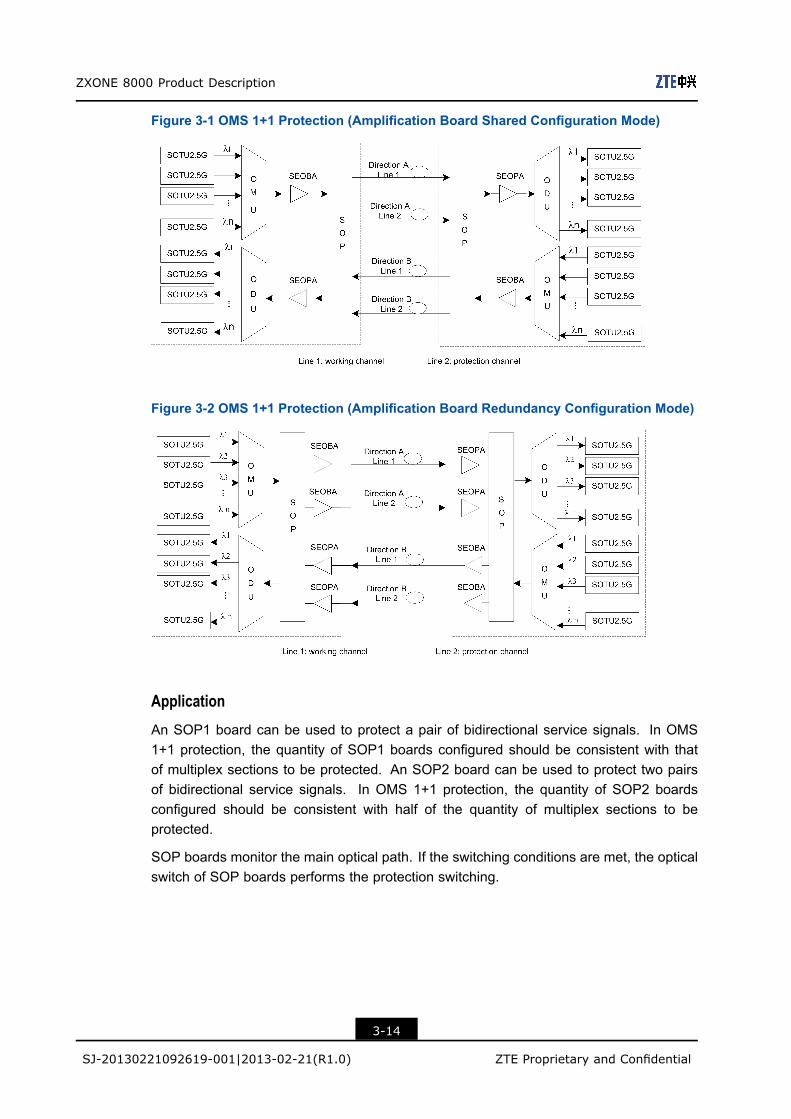
In the OMS 1+1 protection, lines of each segment are protected in 1+1 mode. According tolocations of amplification boards, OMS 1+1 protection can be classified into amplificationboard shared configuration mode and amplification board redundancy configuration mode.For the protection on a group of services, see Figure 3-1 and Figure 3-2.
3-13
SJ-20130221092619-001|2013-02-21(R1.0) ZTE Proprietary and Confidential
ZXONE 8000 Product Description
Figure 3-1 OMS 1+1 Protection (Amplification Board Shared Configuration Mode)
Figure 3-2 OMS 1+1 Protection (Amplification Board Redundancy Configuration Mode)
Application
An SOP1 board can be used to protect a pair of bidirectional service signals. In OMS1+1 protection, the quantity of SOP1 boards configured should be consistent with thatof multiplex sections to be protected. An SOP2 board can be used to protect two pairsof bidirectional service signals. In OMS 1+1 protection, the quantity of SOP2 boardsconfigured should be consistent with half of the quantity of multiplex sections to beprotected.
SOP boards monitor the main optical path. If the switching conditions are met, the opticalswitch of SOP boards performs the protection switching.
3-14
SJ-20130221092619-001|2013-02-21(R1.0) ZTE Proprietary and Confidential
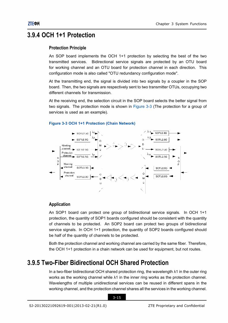
Chapter 3 System Functions
3.9.4 OCH 1+1 Protection
Protection PrincipleAn SOP board implements the OCH 1+1 protection by selecting the best of the twotransmitted services. Bidirectional service signals are protected by an OTU boardfor working channel and an OTU board for protection channel in each direction. Thisconfiguration mode is also called "OTU redundancy configuration mode".
At the transmitting end, the signal is divided into two signals by a coupler in the SOPboard. Then, the two signals are respectively sent to two transmitter OTUs, occupying twodifferent channels for transmission.
At the receiving end, the selection circuit in the SOP board selects the better signal fromtwo signals. The protection mode is shown in Figure 3-3 (The protection for a group ofservices is used as an example).
Figure 3-3 OCH 1+1 Protection (Chain Network)
ApplicationAn SOP1 board can protect one group of bidirectional service signals. In OCH 1+1protection, the quantity of SOP1 boards configured should be consistent with the quantityof channels to be protected. An SOP2 board can protect two groups of bidirectionalservice signals. In OCH 1+1 protection, the quantity of SOP2 boards configured shouldbe half of the quantity of channels to be protected.
Both the protection channel and working channel are carried by the same fiber. Therefore,the OCH 1+1 protection in a chain network can be used for equipment, but not routes.
3.9.5 Two-Fiber Bidirectional OCH Shared ProtectionIn a two-fiber bidirectional OCH shared protection ring, the wavelength λ1 in the outer ringworks as the working channel while λ1 in the inner ring works as the protection channel.Wavelengths of multiple unidirectional services can be reused in different spans in theworking channel, and the protection channel shares all the services in the working channel.
3-15
SJ-20130221092619-001|2013-02-21(R1.0) ZTE Proprietary and Confidential
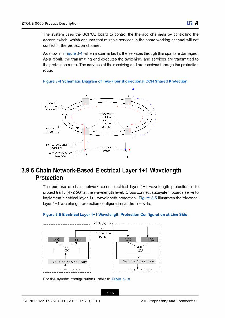
ZXONE 8000 Product Description
The system uses the SOPCS board to control the the add channels by controlling theaccess switch, which ensures that multiple services in the same working channel will notconflict in the protection channel.
As shown in Figure 3-4, when a span is faulty, the services through this span are damaged.As a result, the transmitting end executes the switching, and services are transmitted tothe protection route. The services at the receiving end are received through the protectionroute.
Figure 3-4 Schematic Diagram of Two-Fiber Bidirectional OCH Shared Protection
3.9.6 Chain Network-Based Electrical Layer 1+1 WavelengthProtection
The purpose of chain network-based electrical layer 1+1 wavelength protection is toprotect traffic (4×2.5G) at the wavelength level. Cross connect subsystem boards serve toimplement electrical layer 1+1 wavelength protection. Figure 3-5 illustrates the electricallayer 1+1 wavelength protection configuration at the line side.
Figure 3-5 Electrical Layer 1+1 Wavelength Protection Configuration at Line Side
For the system configurations, refer to Table 3-18.
3-16
SJ-20130221092619-001|2013-02-21(R1.0) ZTE Proprietary and Confidential
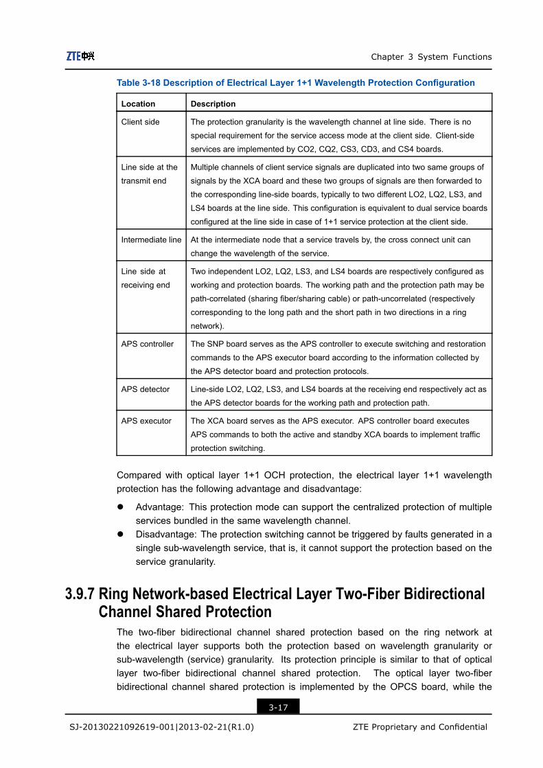
Chapter 3 System Functions
Table 3-18 Description of Electrical Layer 1+1 Wavelength Protection Configuration
Location Description
Client side The protection granularity is the wavelength channel at line side. There is no
special requirement for the service access mode at the client side. Client-side
services are implemented by CO2, CQ2, CS3, CD3, and CS4 boards.
Line side at the
transmit end
Multiple channels of client service signals are duplicated into two same groups of
signals by the XCA board and these two groups of signals are then forwarded to
the corresponding line-side boards, typically to two different LO2, LQ2, LS3, and
LS4 boards at the line side. This configuration is equivalent to dual service boards
configured at the line side in case of 1+1 service protection at the client side.
Intermediate line At the intermediate node that a service travels by, the cross connect unit can
change the wavelength of the service.
Line side at
receiving end
Two independent LO2, LQ2, LS3, and LS4 boards are respectively configured as
working and protection boards. The working path and the protection path may be
path-correlated (sharing fiber/sharing cable) or path-uncorrelated (respectively
corresponding to the long path and the short path in two directions in a ring
network).
APS controller The SNP board serves as the APS controller to execute switching and restoration
commands to the APS executor board according to the information collected by
the APS detector board and protection protocols.
APS detector Line-side LO2, LQ2, LS3, and LS4 boards at the receiving end respectively act as
the APS detector boards for the working path and protection path.
APS executor The XCA board serves as the APS executor. APS controller board executes
APS commands to both the active and standby XCA boards to implement traffic
protection switching.
Compared with optical layer 1+1 OCH protection, the electrical layer 1+1 wavelengthprotection has the following advantage and disadvantage:
l Advantage: This protection mode can support the centralized protection of multipleservices bundled in the same wavelength channel.
l Disadvantage: The protection switching cannot be triggered by faults generated in asingle sub-wavelength service, that is, it cannot support the protection based on theservice granularity.
3.9.7 Ring Network-based Electrical Layer Two-Fiber BidirectionalChannel Shared Protection
The two-fiber bidirectional channel shared protection based on the ring network atthe electrical layer supports both the protection based on wavelength granularity orsub-wavelength (service) granularity. Its protection principle is similar to that of opticallayer two-fiber bidirectional channel shared protection. The optical layer two-fiberbidirectional channel shared protection is implemented by the OPCS board, while the
3-17
SJ-20130221092619-001|2013-02-21(R1.0) ZTE Proprietary and Confidential

ZXONE 8000 Product Description
electrical layer one is implemented by cross-connect subsystem boards. The combinationof cross connect subsystem boards provides the same logical functions as the OPCSboard. Figure 3-6 shows the principle of electrical layer two-fiber channel sharedprotection.
Figure 3-6 Electrical Layer Two-Fiber Bidirectional Channel Shared Ring NetworkProtection Configuration
l Relationship between working path and protection path
The working path and the protection path are uncorrelated in electrical layer two-fiberbidirectional channel shared ring. They respectively correspond to the short path andthe long path in the ring network.
l Protocol execution
It is necessary to execute the APS protocol in electrical layer two-fiber bidirectionalchannel shared ring.
à APS controller: The SNP board serves as the APS controller.
à APS detector: Line-side LO2, LQ2, LS3, and LS4 boards at the receivingend respectively act as the APS detector boards for the working path and theprotection path. Client-side CO2, CQ2, CS3, CD3, and CS4 boards act as thedetector board for service signals (STM-1/4/16), and the detection signals areshared by working and protection channels.
à APS executor: The SNP board sends APS commands to both the active andstandby XCA boards in the cross-connect subsystem to implement the trafficprotection switching.
l Features
à Advantage: The protection granularity is flexible, which can be a sub-wavelengthtraffic or aggregate wavelength signal. Either line fault or service signal fault cantrigger protection switching. The electrical layer two-fiber bidirectional channelshared protection can implement cross-span protection with protection channelshared on the whole ring.
3-18
SJ-20130221092619-001|2013-02-21(R1.0) ZTE Proprietary and Confidential
Chapter 3 System Functions
à Disadvantage: The implementation mechanism of this protection mode iscomplex.
3.9.8 Protection Capability for EMS ChannelThe ZXONE 8000 system can configure EMS channel standby route. When the opticalmonitoring channel fails to work, SNP boards can ensure the transmission and exchangeof monitoring messages through the standby route.
Note:
Standby routes refer to Ethernet routes connecting SNP boards in NEs and the EMScomputer. In practice, network interfaces of standby routes can be connected toSEIA1/SEIA2 boards to provide standby routes for monitoring channels.
3.10 Clock Management FunctionThe ZXONE 8000 system uses a separate clock board CLK to support the clock transferfunction and generate the system clock. The CLK board supports 1+1 backup, maintainssynchronization betweenmaster/slave output clocks and the system clock, and cooperateswith the system to implement seamless switching between the master clock board and theslave clock board.
The external clock can be accessed from the clock panel or through an external clockinterface board.
l The ZXONE 8000 system can extract clock sources from service boards, and usethem as the system clock sources.
l CLK clock boards support the three modes specified by ITU-T G.813: free running,holdover, and automatic lock. The three modes can be configured in the EMS.
3.11 Clock Synchronization FunctionThe ZXONE 8000 clock synchronization function supports transmitting clocksynchronization signals among subracks and networks. It has the following features:
l Supports the clock synchronization and the time synchronization to meet therequirements for time synchronization accuracy.
l The physical-layer synchronization mechanism extracts clock from the serialbit stream in physical channel of transmission link to implement the frequencysynchronization.
l The time synchronization complies with the IEEE 1588 V2 protocol. The ZXONE 8000system provides an out-of-band time synchronization interface between 1pps+TODand FE to implement the out-of-band time transmission.
3-19
SJ-20130221092619-001|2013-02-21(R1.0) ZTE Proprietary and Confidential
ZXONE 8000 Product Description
l Uses the Best Master Clock (BMC) algorithm to select a clock. The BMC algorithmcompares the descriptions of two or more clocks, and selects the better one. TheOrdinary Clock (OC), Boundary Clock (BC ) , and Transparent Clock (TC) aresupported.
l Supports processing the Synchronization Status Message (SSM) and the delay com-pensation.
l Supports the protection switch of active/standby clock sources.
The BITS 2M interface, subrack-interconnecting Ethernet interface, or BITS interface areused to implement the system clock synchronization between ZXONE 8000 subracks. TheBITS interfaces can interconnect through 2 MHz or 2 Mbit/s clock. The 2 MBit/s clock cantransfer SSM messages.
3-20
SJ-20130221092619-001|2013-02-21(R1.0) ZTE Proprietary and Confidential
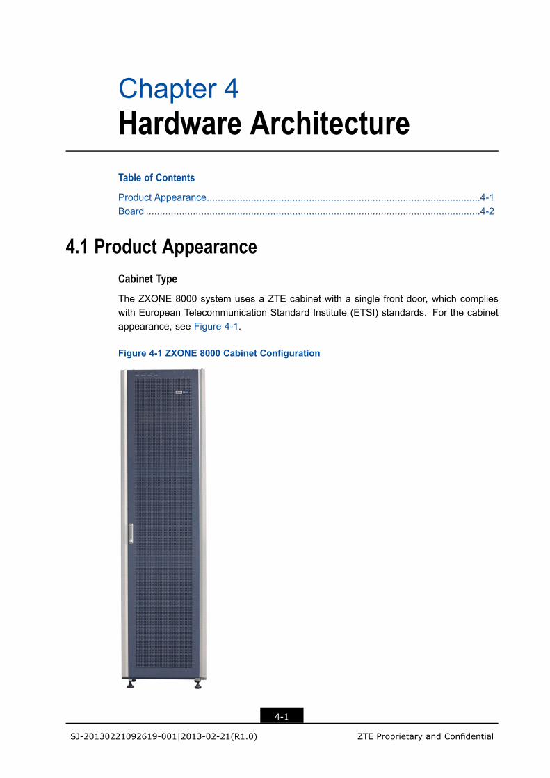
Chapter 4Hardware ArchitectureTable of Contents
Product Appearance...................................................................................................4-1Board .........................................................................................................................4-2
4.1 Product AppearanceCabinet Type
The ZXONE 8000 system uses a ZTE cabinet with a single front door, which complieswith European Telecommunication Standard Institute (ETSI) standards. For the cabinetappearance, see Figure 4-1.
Figure 4-1 ZXONE 8000 Cabinet Configuration
4-1
SJ-20130221092619-001|2013-02-21(R1.0) ZTE Proprietary and Confidential
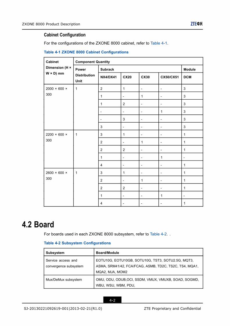
ZXONE 8000 Product Description
Cabinet Configuration
For the configurations of the ZXONE 8000 cabinet, refer to Table 4-1.
Table 4-1 ZXONE 8000 Cabinet Configurations
Component Quantity
Subrack Module
CabinetDimension (H ×W × D) mm
PowerDistributionUnit
NX4/DX41 CX20 CX30 CX50/CX51 DCM
2 1 - - 3
1 - 1 - 3
1 2 - - 3
- - - 1 3
- 3 - - 3
2000 × 600 ×
300
1
3 - - - 3
3 1 - - 1
2 - 1 - 1
2 2 - - 1
1 - - 1 -
2200 × 600 ×
300
1
4 - - - 1
3 1 - - 1
2 - 1 - 1
2 2 - - 1
1 - - 1 -
2600 × 600 ×
300
1
4 - - - 1
4.2 BoardFor boards used in each ZXONE 8000 subsystem, refer to Table 4-2. .
Table 4-2 Subsystem Configurations
Subsystem Board/Module
Service access and
convergence subsystem
EOTU10G, EOTU10GB, SOTU10G, TST3, SOTU2.5G, MQT3,
ASMA, SRM41/42, FCA/FCAG, ASMB, TD2C, TS2C, TS4, MQA1,
MQA2, MJA, MOM2
Mux/DeMux subsystem OMU, ODU, ODUB,OCI, SSDM, VMUX, VMUXB, SOAD, SOGMD,
WBU, WSU, WBM, PDU,
4-2
SJ-20130221092619-001|2013-02-21(R1.0) ZTE Proprietary and Confidential

Chapter 4 Hardware Architecture
Subsystem Board/Module
Optical amplification
subsystem
SEOBA, SEOPA, SEOLA, EONA, EOBAH, LAC, DRA
Monitoring subsystem SNP, SCC, SEIA1/SEIA2, CCP, SOSCB, TIS, ETI, EIC
Protection subsystem SOP, OMCP, SOPMS, SOPCS
Cross-connect subsystem XCA, CH1, LO2, CO2, LQ2, LD2B, CQ2, CLK, CS3, CD3, LS3,
CS4, LS4
Optical layer management
subsystem
OWM, OPM, EOPM, EOWM
Power supply subsystem PWD, FCC, SPWA, SFANA, PWE
RPOA subsystem RPU, RGU
For the ZXONE 8000 system architecture on the basis of functional modules, see Figure4-2. The ZXONE 8000 system is composed of nine functional subsystems. They areindependent from each other but operate in coordination.
Figure 4-2 ZXONE 8000 System Architecture
Note:
In application, functional modules on each site should be configured as required.
The service flows between functional subsystems are described as follows:
l After service signals are received in the service access and convergence subsystem,they are sent to the Mux/Demux subsystem for multiplexing. The multiplexed signalsare then sent to the optical amplifier subsystem for amplification. The amplified signalsare transmitted to the optical-fiber line.
4-3
SJ-20130221092619-001|2013-02-21(R1.0) ZTE Proprietary and Confidential
ZXONE 8000 Product Description
After service signals are received in the service access and convergence subsystem,they are sent to the optical amplifier subsystem for amplification. The amplifiedoptical signals are then sent to the Mux/Demux subsystem for demultiplexing. Thedemultiplexed signals are sent to the service boards.
l To implement the service protection, the protection subsystem must be configured.The protection subsystem can be located before or after the service access andconvergence subsystem.
l To switch services, the cross-connect subsystem must be configured. Client servicesignals are accessed, switched, and aggregated at the cross-connect system, andthen sent to the optical-fiber line.
l To implement the ultra-long-haul single-span transmission, the RPOA subsystemmust be configured after the optical amplifier subsystem.
4-4
SJ-20130221092619-001|2013-02-21(R1.0) ZTE Proprietary and Confidential
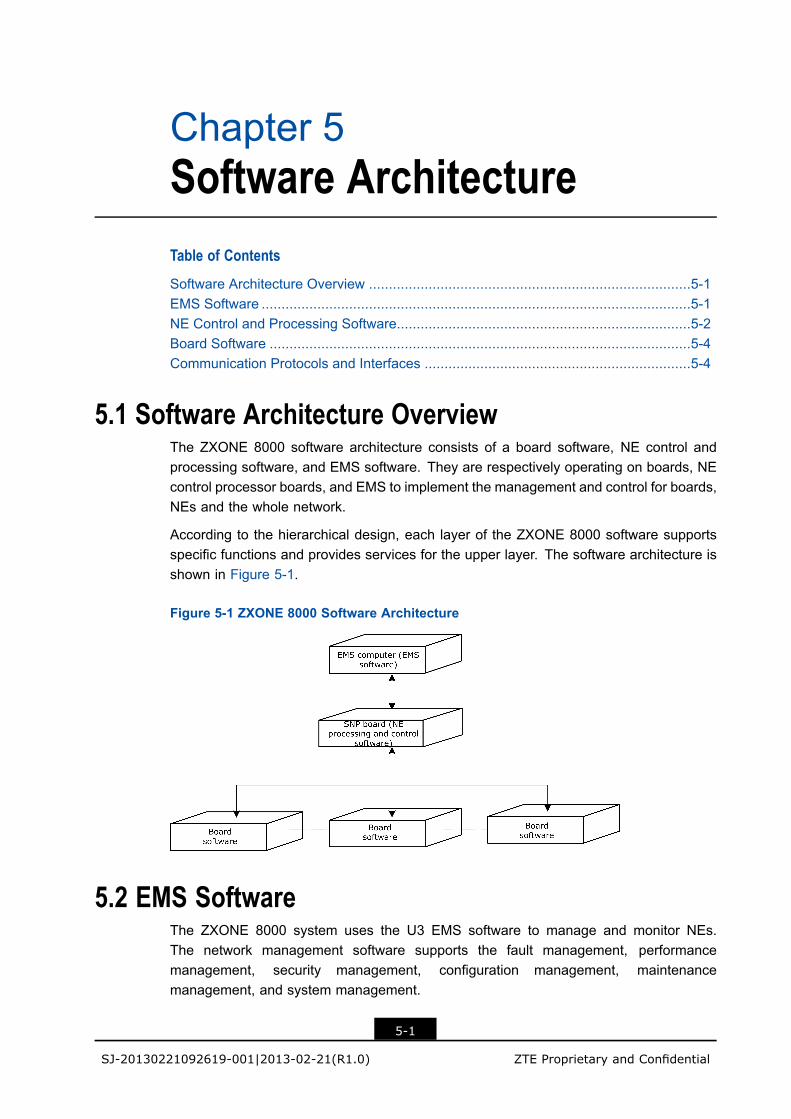
Chapter 5Software ArchitectureTable of Contents
Software Architecture Overview .................................................................................5-1EMS Software ............................................................................................................5-1NE Control and Processing Software..........................................................................5-2Board Software ..........................................................................................................5-4Communication Protocols and Interfaces ...................................................................5-4
5.1 Software Architecture OverviewThe ZXONE 8000 software architecture consists of a board software, NE control andprocessing software, and EMS software. They are respectively operating on boards, NEcontrol processor boards, and EMS to implement the management and control for boards,NEs and the whole network.
According to the hierarchical design, each layer of the ZXONE 8000 software supportsspecific functions and provides services for the upper layer. The software architecture isshown in Figure 5-1.
Figure 5-1 ZXONE 8000 Software Architecture
5.2 EMS SoftwareThe ZXONE 8000 system uses the U3 EMS software to manage and monitor NEs.The network management software supports the fault management, performancemanagement, security management, configuration management, maintenancemanagement, and system management.
5-1
SJ-20130221092619-001|2013-02-21(R1.0) ZTE Proprietary and Confidential

ZXONE 8000 Product Description
The EMS structure is shown in Figure 5-2.
Figure 5-2 EMS Structure
l Manager
It is also referred to as Server. Compared to Graphical User Interface (GUI), Managerworks as a Server. Through Qx interfaces, Manager sends management commandsto the corresponding NE control and processing software, receives messages fromNE control and processing software, and saves all the network management dataincluding the basic data of system management, configuration management, andalarm maintenance in the database. Manager only saves management data in thelocal network.
l Graphical User Interface (GUI)
It is also referred to as Client. The GUI provides graphical interfaces for users. Theusers can implement configuration management, fault management, performancemanagement, security management, maintenance management and systemmanagement in the GUI. The GUI does not save dynamic network managementdata, which are retrieved from Database by Manager when the users use the GUI.
l Database
The Database stores data about information query, configuration and alarm forinterfaces and management functional modules. It also implements the processingof data consistency.
5.3 NE Control and Processing SoftwareNE control and processing software is located on the Smart Node Processor (SNP) boardto manage, monitor and control the board operation status in the NE. As a communicationservice unit between the network management system and boards, it implements controland management for NEs. For the functions supported by the NE control and processingsoftware, refer to Table 5-1:
5-2
SJ-20130221092619-001|2013-02-21(R1.0) ZTE Proprietary and Confidential
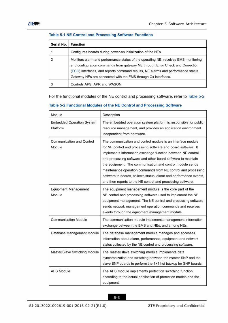
Chapter 5 Software Architecture
Table 5-1 NE Control and Processing Software Functions
Serial No. Function
1 Configures boards during power-on initialization of the NEs.
2 Monitors alarm and performance status of the operating NE, receives EMS monitoring
and configuration commands from gateway NE through Error Check and Correction
(ECC) interfaces, and reports command results, NE alarms and performance status.
Gateway NEs are connected with the EMS through Ox interfaces.
3 Controls APS, APR and WASON.
For the functional modules of the NE control and processing software, refer to Table 5-2:
Table 5-2 Functional Modules of the NE Control and Processing Software
Module Description
Embedded Operation System
Platform
The embedded operation system platform is responsible for public
resource management, and provides an application environment
independent from hardware.
Communication and Control
Module
The communication and control module is an interface module
for NE control and processing software and board software. It
implements information exchange function between NE control
and processing software and other board software to maintain
the equipment. The communication and control module sends
maintenance operation commands from NE control and processing
software to boards, collects status, alarm and performance events,
and then reports to the NE control and processing software.
Equipment Management
Module
The equipment management module is the core part of the
NE control and processing software used to implement the NE
equipment management. The NE control and processing software
sends network management operation commands and receives
events through the equipment management module.
Communication Module The communication module implements management information
exchange between the EMS and NEs, and among NEs.
Database Management Module The database management module manages and accesses
information about alarm, performance, equipment and network
status collected by the NE control and processing software.
Master/Slave Switching Module The master/slave switching module implements data
synchronization and switching between the master SNP and the
slave SNP boards to perform the 1+1 hot backup for SNP boards.
APS Module The APS module implements protection switching function
according to the actual application of protection modes and the
equipment.
5-3
SJ-20130221092619-001|2013-02-21(R1.0) ZTE Proprietary and Confidential
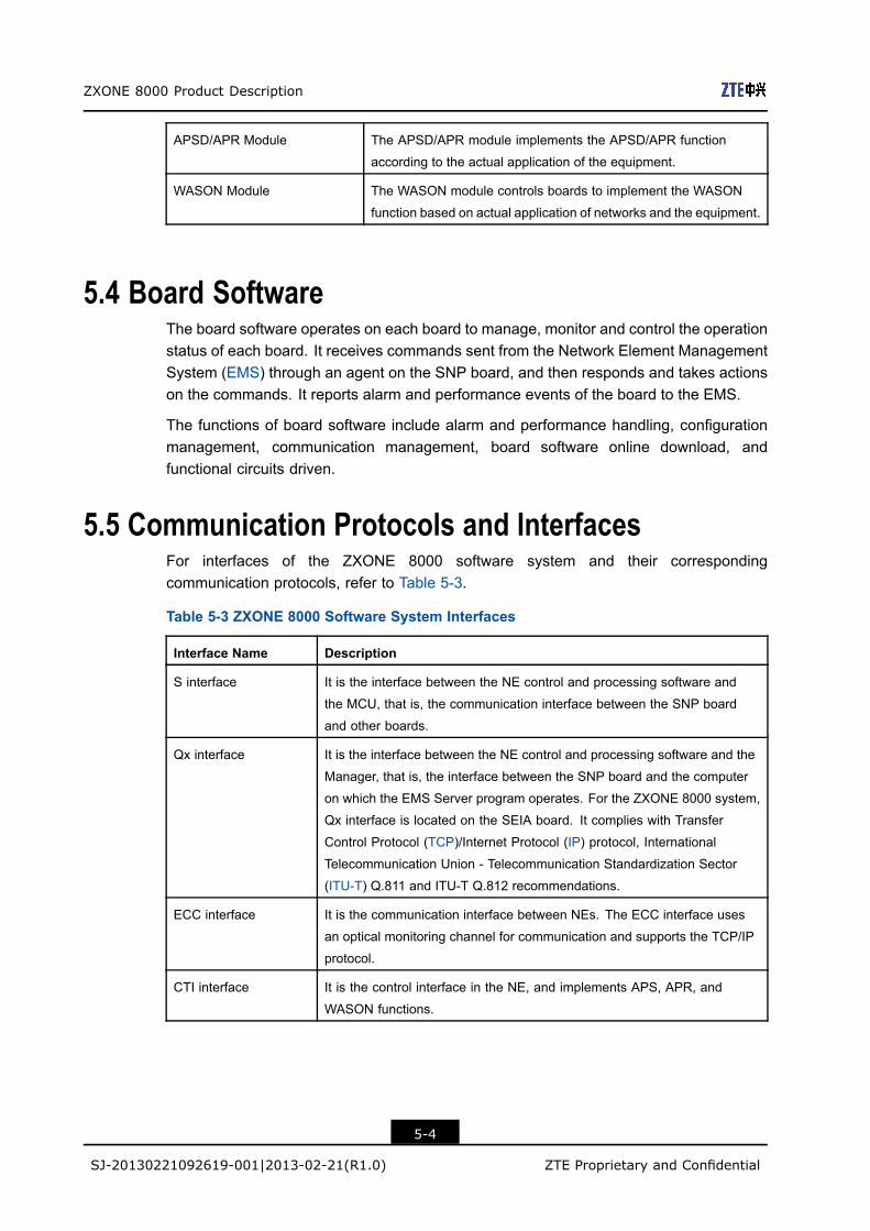
ZXONE 8000 Product Description
APSD/APR Module The APSD/APR module implements the APSD/APR function
according to the actual application of the equipment.
WASON Module The WASON module controls boards to implement the WASON
function based on actual application of networks and the equipment.
5.4 Board SoftwareThe board software operates on each board to manage, monitor and control the operationstatus of each board. It receives commands sent from the Network Element ManagementSystem (EMS) through an agent on the SNP board, and then responds and takes actionson the commands. It reports alarm and performance events of the board to the EMS.
The functions of board software include alarm and performance handling, configurationmanagement, communication management, board software online download, andfunctional circuits driven.
5.5 Communication Protocols and InterfacesFor interfaces of the ZXONE 8000 software system and their correspondingcommunication protocols, refer to Table 5-3.
Table 5-3 ZXONE 8000 Software System Interfaces
Interface Name Description
S interface It is the interface between the NE control and processing software and
the MCU, that is, the communication interface between the SNP board
and other boards.
Qx interface It is the interface between the NE control and processing software and the
Manager, that is, the interface between the SNP board and the computer
on which the EMS Server program operates. For the ZXONE 8000 system,
Qx interface is located on the SEIA board. It complies with Transfer
Control Protocol (TCP)/Internet Protocol (IP) protocol, International
Telecommunication Union - Telecommunication Standardization Sector
(ITU-T) Q.811 and ITU-T Q.812 recommendations.
ECC interface It is the communication interface between NEs. The ECC interface uses
an optical monitoring channel for communication and supports the TCP/IP
protocol.
CTI interface It is the control interface in the NE, and implements APS, APR, and
WASON functions.
5-4
SJ-20130221092619-001|2013-02-21(R1.0) ZTE Proprietary and Confidential

Chapter 6Technical SpecificationsTable of Contents
Requirements on Operating Wavelength ....................................................................6-1Service Access and Convergence Subsystem Specifications .....................................6-7Optical Mux/DeMux Subsystem Specifications ........................................................6-15Optical Amplification Subsystem Specifications .......................................................6-27Optical Layer Management Subsystem Specifications..............................................6-37Protection Subsystem Specifications........................................................................6-40Supervision Subsystem Specifications .....................................................................6-42RPOA Subsystem Specifications..............................................................................6-43DCM Technical Specifications ..................................................................................6-44Environment Specifications ......................................................................................6-46Electro Magnetic Compatibility Requirements...........................................................6-51Weight Power consumption Dimensions...................................................................6-52
6.1 Requirements on Operating Wavelength
6.1.1 Allocation of Continuous Wavelengthsl The spacing between wavelengths is 100 GHz when the ZXONE 8000 system is
configured as a system with no more than 40 wavelengths in C band. Table 6-1 liststhe wavelengths allocated in a 40-channel system.
Table 6-1 Wavelength Allocation (40 Channels in C Band with Spacing at 100 GHz)
S/N Central Frequency(THz)
CentralWavelength (nm)
S/N Central Frequency(THz)
Central Wavelength(nm)
1 192.10 1560.61 21 194.10 1544.53
2 192.20 1559.79 22 194.20 1543.73
3 192.30 1558.98 23 194.30 1542.94
4 192.40 1558.17 24 194.40 1542.14
5 192.50 1557.36 25 194.50 1541.35
6 192.60 1556.55 26 194.60 1540.56
7 192.70 1555.75 27 194.70 1539.77
8 192.80 1554.94 28 194.80 1538.98
9 192.90 1554.13 29 194.90 1538.19
6-1
SJ-20130221092619-001|2013-02-21(R1.0) ZTE Proprietary and Confidential
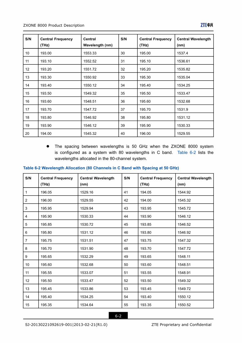
ZXONE 8000 Product Description
S/N Central Frequency(THz)
CentralWavelength (nm)
S/N Central Frequency(THz)
Central Wavelength(nm)
10 193.00 1553.33 30 195.00 1537.4
11 193.10 1552.52 31 195.10 1536.61
12 193.20 1551.72 32 195.20 1535.82
13 193.30 1550.92 33 195.30 1535.04
14 193.40 1550.12 34 195.40 1534.25
15 193.50 1549.32 35 195.50 1533.47
16 193.60 1548.51 36 195.60 1532.68
17 193.70 1547.72 37 195.70 1531.9
18 193.80 1546.92 38 195.80 1531.12
19 193.90 1546.12 39 195.90 1530.33
20 194.00 1545.32 40 196.00 1529.55
l The spacing between wavelengths is 50 GHz when the ZXONE 8000 systemis configured as a system with 80 wavelengths in C band. Table 6-2 lists thewavelengths allocated in the 80-channel system.
Table 6-2 Wavelength Allocation (80 Channels in C Band with Spacing at 50 GHz)
S/N Central Frequency(THz)
Central Wavelength(nm)
S/N Central Frequency(THz)
Central Wavelength(nm)
1 196.05 1529.16 41 194.05 1544.92
2 196.00 1529.55 42 194.00 1545.32
3 195.95 1529.94 43 193.95 1545.72
4 195.90 1530.33 44 193.90 1546.12
5 195.85 1530.72 45 193.85 1546.52
6 195.80 1531.12 46 193.80 1546.92
7 195.75 1531.51 47 193.75 1547.32
8 195.70 1531.90 48 193.70 1547.72
9 195.65 1532.29 49 193.65 1548.11
10 195.60 1532.68 50 193.60 1548.51
11 195.55 1533.07 51 193.55 1548.91
12 195.50 1533.47 52 193.50 1549.32
13 195.45 1533.86 53 193.45 1549.72
14 195.40 1534.25 54 193.40 1550.12
15 195.35 1534.64 55 193.35 1550.52
6-2
SJ-20130221092619-001|2013-02-21(R1.0) ZTE Proprietary and Confidential
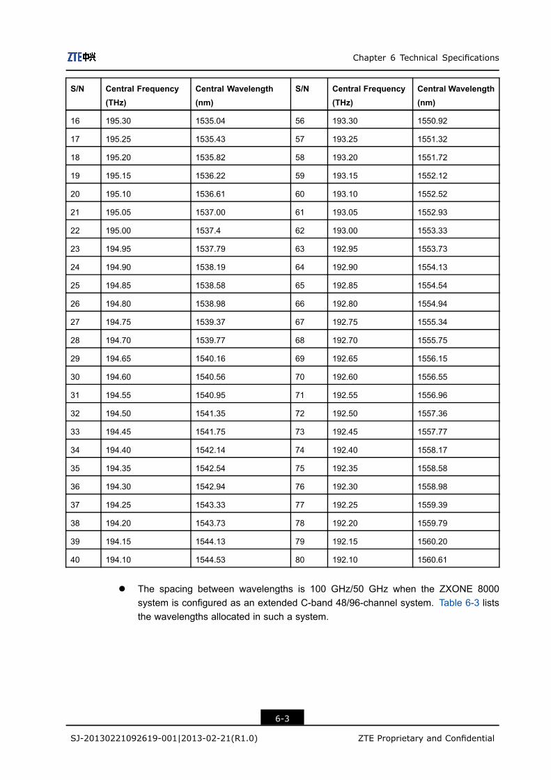
Chapter 6 Technical Specifications
S/N Central Frequency(THz)
Central Wavelength(nm)
S/N Central Frequency(THz)
Central Wavelength(nm)
16 195.30 1535.04 56 193.30 1550.92
17 195.25 1535.43 57 193.25 1551.32
18 195.20 1535.82 58 193.20 1551.72
19 195.15 1536.22 59 193.15 1552.12
20 195.10 1536.61 60 193.10 1552.52
21 195.05 1537.00 61 193.05 1552.93
22 195.00 1537.4 62 193.00 1553.33
23 194.95 1537.79 63 192.95 1553.73
24 194.90 1538.19 64 192.90 1554.13
25 194.85 1538.58 65 192.85 1554.54
26 194.80 1538.98 66 192.80 1554.94
27 194.75 1539.37 67 192.75 1555.34
28 194.70 1539.77 68 192.70 1555.75
29 194.65 1540.16 69 192.65 1556.15
30 194.60 1540.56 70 192.60 1556.55
31 194.55 1540.95 71 192.55 1556.96
32 194.50 1541.35 72 192.50 1557.36
33 194.45 1541.75 73 192.45 1557.77
34 194.40 1542.14 74 192.40 1558.17
35 194.35 1542.54 75 192.35 1558.58
36 194.30 1542.94 76 192.30 1558.98
37 194.25 1543.33 77 192.25 1559.39
38 194.20 1543.73 78 192.20 1559.79
39 194.15 1544.13 79 192.15 1560.20
40 194.10 1544.53 80 192.10 1560.61
l The spacing between wavelengths is 100 GHz/50 GHz when the ZXONE 8000system is configured as an extended C-band 48/96-channel system. Table 6-3 liststhe wavelengths allocated in such a system.
6-3
SJ-20130221092619-001|2013-02-21(R1.0) ZTE Proprietary and Confidential
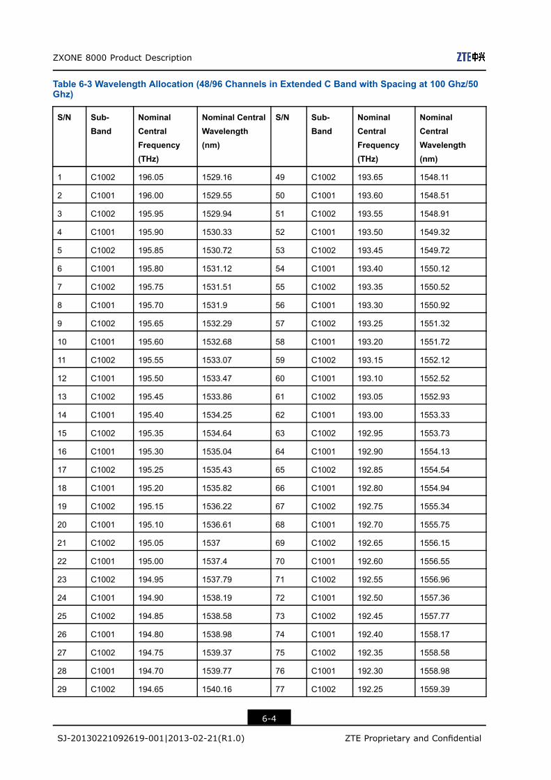
ZXONE 8000 Product Description
Table 6-3 Wavelength Allocation (48/96 Channels in Extended C Band with Spacing at 100 Ghz/50Ghz)
S/N Sub-Band
NominalCentralFrequency(THz)
Nominal CentralWavelength(nm)
S/N Sub-Band
NominalCentralFrequency(THz)
NominalCentralWavelength(nm)
1 C1002 196.05 1529.16 49 C1002 193.65 1548.11
2 C1001 196.00 1529.55 50 C1001 193.60 1548.51
3 C1002 195.95 1529.94 51 C1002 193.55 1548.91
4 C1001 195.90 1530.33 52 C1001 193.50 1549.32
5 C1002 195.85 1530.72 53 C1002 193.45 1549.72
6 C1001 195.80 1531.12 54 C1001 193.40 1550.12
7 C1002 195.75 1531.51 55 C1002 193.35 1550.52
8 C1001 195.70 1531.9 56 C1001 193.30 1550.92
9 C1002 195.65 1532.29 57 C1002 193.25 1551.32
10 C1001 195.60 1532.68 58 C1001 193.20 1551.72
11 C1002 195.55 1533.07 59 C1002 193.15 1552.12
12 C1001 195.50 1533.47 60 C1001 193.10 1552.52
13 C1002 195.45 1533.86 61 C1002 193.05 1552.93
14 C1001 195.40 1534.25 62 C1001 193.00 1553.33
15 C1002 195.35 1534.64 63 C1002 192.95 1553.73
16 C1001 195.30 1535.04 64 C1001 192.90 1554.13
17 C1002 195.25 1535.43 65 C1002 192.85 1554.54
18 C1001 195.20 1535.82 66 C1001 192.80 1554.94
19 C1002 195.15 1536.22 67 C1002 192.75 1555.34
20 C1001 195.10 1536.61 68 C1001 192.70 1555.75
21 C1002 195.05 1537 69 C1002 192.65 1556.15
22 C1001 195.00 1537.4 70 C1001 192.60 1556.55
23 C1002 194.95 1537.79 71 C1002 192.55 1556.96
24 C1001 194.90 1538.19 72 C1001 192.50 1557.36
25 C1002 194.85 1538.58 73 C1002 192.45 1557.77
26 C1001 194.80 1538.98 74 C1001 192.40 1558.17
27 C1002 194.75 1539.37 75 C1002 192.35 1558.58
28 C1001 194.70 1539.77 76 C1001 192.30 1558.98
29 C1002 194.65 1540.16 77 C1002 192.25 1559.39
6-4
SJ-20130221092619-001|2013-02-21(R1.0) ZTE Proprietary and Confidential
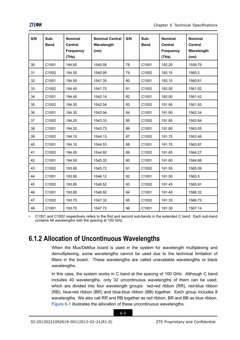
Chapter 6 Technical Specifications
S/N Sub-Band
NominalCentralFrequency(THz)
Nominal CentralWavelength(nm)
S/N Sub-Band
NominalCentralFrequency(THz)
NominalCentralWavelength(nm)
30 C1001 194.60 1540.56 78 C1001 192.20 1559.79
31 C1002 194.55 1540.95 79 C1002 192.15 1560.2
32 C1001 194.50 1541.35 80 C1001 192.10 1560.61
33 C1002 194.45 1541.75 81 C1002 192.05 1561.02
34 C1001 194.40 1542.14 82 C1001 192.00 1561.42
35 C1002 194.35 1542.54 83 C1002 191.95 1561.83
36 C1001 194.30 1542.94 84 C1001 191.90 1562.24
37 C1002 194.25 1543.33 85 C1002 191.85 1562.64
38 C1001 194.20 1543.73 86 C1001 191.80 1563.05
39 C1002 194.15 1544.13 87 C1002 191.75 1563.46
40 C1001 194.10 1544.53 88 C1001 191.70 1563.87
41 C1002 194.05 1544.92 89 C1002 191.65 1564.27
42 C1001 194.00 1545.32 90 C1001 191.60 1564.68
43 C1002 193.95 1545.72 91 C1002 191.55 1565.09
44 C1001 193.90 1546.12 92 C1001 191.50 1565.5
45 C1002 193.85 1546.52 93 C1002 191.45 1565.91
46 C1001 193.80 1546.92 94 C1001 191.40 1566.32
47 C1002 193.75 1547.32 95 C1002 191.35 1566.73
48 C1001 193.70 1547.72 96 C1001 191.30 1567.14
• C1001 and C1002 respectively refers to the first and second sub-bands in the extended C band. Each sub-bandcontains 48 wavelengths with the spacing at 100 GHz.
6.1.2 Allocation of Uncontinuous WavelengthsWhen the Mux/DeMux board is used in the system for wavelength multiplexing anddemultiplexing, some wavelengths cannot be used due to the technical limitation offilters in the board. These wavelengths are called unavailable wavelengths or blackwavelengths.
In this case, the system works in C band at the spacing of 100 GHz. Although C bandincludes 40 wavelengths, only 32 uncontinuous wavelengths of them can be used,which are divided into four wavelength groups: red-red ribbon (RR), red-blue ribbon(RB), blue-red ribbon (BR) and blue-blue ribbon (BB) together. Each group includes 8wavelengths. We also call RR and RB together as red ribbon, BR and BB as blue ribbon.Figure 6-1 illustrates the allocation of these uncontinuous wavelengths.
6-5
SJ-20130221092619-001|2013-02-21(R1.0) ZTE Proprietary and Confidential

ZXONE 8000 Product Description
Figure 6-1 Allocation of Uncontinuous Wavelengths
Note:
λ21 represents the wavelength with the frequency 192.10 THz. λ28 represents thewavelength with the frequency 192.8 THz, and so on.
The detailed allocation of uncontinuous wavelengths is listed in Table 6-4. Wavelengthof 9, 10, 19, 20, 21, 22, 31 and 32 are marked grey in the table and are unavailablewavelengths.
Table 6-4 Uncontinuous Wavelengths and Corresponding Central Frequencies
S/N CentralFrequency(THz)
CentralWavelength(nm)
S/N CentralFrequency (THz)
CentralWavelength (nm)
1 192.10 1560.61 21 194.10 1544.53
2 192.20 1559.79 22 194.20 1543.73
3 192.30 1558.98 23 194.30 1542.94
4 192.40 1558.17 24 194.40 1542.14
5 192.50 1557.36 25 194.50 1541.35
6 192.60 1556.55 26 194.60 1540.56
7 192.70 1555.75 27 194.70 1539.77
8 192.80 1554.94 28 194.80 1538.98
9 192.90 1554.13 29 194.90 1538.19
10 193 1553.33 30 195 1537.40
11 193.10 1552.52 31 195.10 1536.61
12 193.20 1551.72 32 195.20 1535.82
13 193.30 1550.92 33 195.30 1535.04
14 193.40 1550.12 34 195.40 1534.25
15 193.50 1549.32 35 195.50 1533.47
16 193.60 1548.51 36 195.60 1532.68
6-6
SJ-20130221092619-001|2013-02-21(R1.0) ZTE Proprietary and Confidential
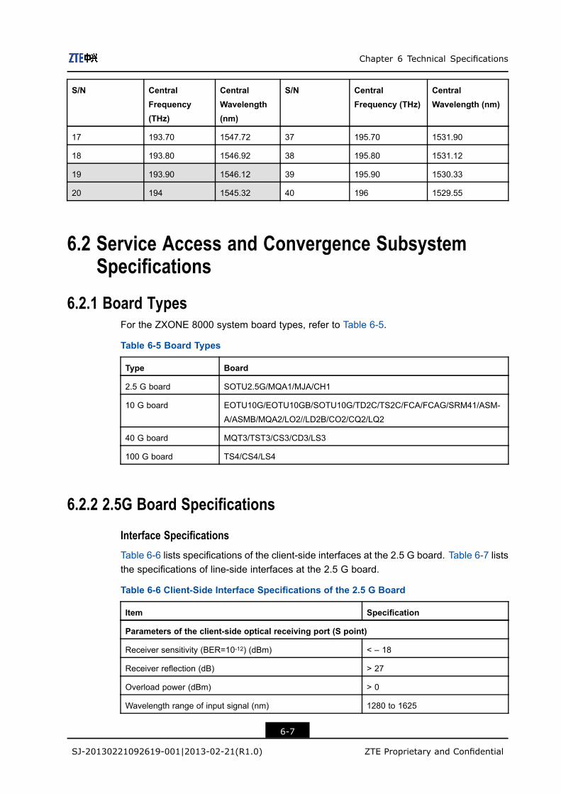
Chapter 6 Technical Specifications
S/N CentralFrequency(THz)
CentralWavelength(nm)
S/N CentralFrequency (THz)
CentralWavelength (nm)
17 193.70 1547.72 37 195.70 1531.90
18 193.80 1546.92 38 195.80 1531.12
19 193.90 1546.12 39 195.90 1530.33
20 194 1545.32 40 196 1529.55
6.2 Service Access and Convergence SubsystemSpecifications
6.2.1 Board TypesFor the ZXONE 8000 system board types, refer to Table 6-5.
Table 6-5 Board Types
Type Board
2.5 G board SOTU2.5G/MQA1/MJA/CH1
10 G board EOTU10G/EOTU10GB/SOTU10G/TD2C/TS2C/FCA/FCAG/SRM41/ASM-
A/ASMB/MQA2/LO2//LD2B/CO2/CQ2/LQ2
40 G board MQT3/TST3/CS3/CD3/LS3
100 G board TS4/CS4/LS4
6.2.2 2.5G Board Specifications
Interface SpecificationsTable 6-6 lists specifications of the client-side interfaces at the 2.5 G board. Table 6-7 liststhe specifications of line-side interfaces at the 2.5 G board.
Table 6-6 Client-Side Interface Specifications of the 2.5 G Board
Item Specification
Parameters of the client-side optical receiving port (S point)
Receiver sensitivity (BER=10-12) (dBm) < – 18
Receiver reflection (dB) > 27
Overload power (dBm) > 0
Wavelength range of input signal (nm) 1280 to 1625
6-7
SJ-20130221092619-001|2013-02-21(R1.0) ZTE Proprietary and Confidential
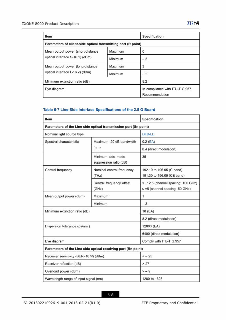
ZXONE 8000 Product Description
Item Specification
Parameters of client-side optical transmitting port (R point)
Maximum 0Mean output power (short-distance
optical interface S-16.1) (dBm) Minimum – 5
Maximum 3Mean output power (long-distance
optical interface L-16.2) (dBm) Minimum – 2
Minimum extinction ratio (dB) 8.2
Eye diagram In compliance with ITU-T G.957
Recommendation
Table 6-7 Line-Side Interface Specifications of the 2.5 G Board
Item Specification
Parameters of the Line-side optical transmission port (Sn point)
Nominal light source type DFB-LD
0.2 (EA)Maximum -20 dB bandwidth
(nm) 0.4 (direct modulation)
Spectral characteristic
Minimum side mode
suppression ratio (dB)
35
Nominal central frequency
(THz)
192.10 to 196.05 (C band)
191.30 to 196.05 (CE band)
Central frequency
Central frequency offset
(GHz)
≤ ±12.5 (channel spacing: 100 GHz)
≤ ±5 (channel spacing: 50 GHz)
Maximum 1Mean output power (dBm)
Minimum – 3
10 (EA)Minimum extinction ratio (dB)
8.2 (direct modulation)
12800 (EA)Dispersion tolerance (ps/nm )
6400 (direct modulation)
Eye diagram Comply with ITU-T G.957
Parameters of the Line-side optical receiving port (Rn point)
Receiver sensitivity (BER=10-12) (dBm) < – 25
Receiver reflection (dB) > 27
Overload power (dBm) > – 9
Wavelength range of input signal (nm) 1280 to 1625
6-8
SJ-20130221092619-001|2013-02-21(R1.0) ZTE Proprietary and Confidential
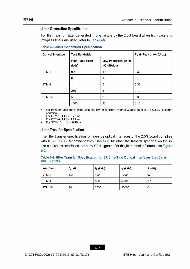
Chapter 6 Technical Specifications
Jitter Generation SpecificationFor the maximum jitter generated in one minute by the 2.5G board when high-pass andlow-pass filters are used, refer to Table 6-8.
Table 6-8 Jitter Generation Specification
Test BandwidthOptical Interface
High-Pass Filter(kHz)
Low-Pass Filter (MHz,-60 dB/dec)
Peak-Peak Jitter (UIpp)
0.5 1.3 0.30STM-1
6.5 1.3 0.10
1 5 0.30STM-4
250 5 0.10
5 20 0.30STM-16
1000 20 0.10
• For transfer functions of high-pass and low-pass filters, refer to Clause 35 of ITU-T G.825 Recommendation.
• For STM-1, 1 UI = 6.43 ns• For STM-4, 1 UI = 1.61 ns• For STM-16, 1 UI = 0.40 ns
Jitter Transfer SpecificationThe jitter transfer specification for line-side optical interfaces of the 2.5G board complieswith ITU-T G.783 Recommendation. Table 6-9 lists the jitter transfer specification for 3Rline-side optical interfaces that carry SDH signals. For the jitter transfer feature, see Figure6-2.
Table 6-9 Jitter Transfer Specification for 3R Line-Side Optical Interfaces that CarrySDH Signals
Interface fL (kHz) fC (kHz) fH (kHz) P (dB)
STM-1 1.3 130 1300 0.1
STM-4 5 500 5000 0.1
STM-16 20 2000 20000 0.1
6-9
SJ-20130221092619-001|2013-02-21(R1.0) ZTE Proprietary and Confidential

ZXONE 8000 Product Description
Figure 6-2 Jitter Transfer Characteristics of Line-Side Optical Interfaces
6.2.3 10G Board Specifications
Interface Specifications
Table 6-10 lists the interface specifications at the client side of the 10 G board. Table 6-11lists the interface specifications at the line side of the 10 G board.
Table 6-10 Client-Side Interface Specifications of the 10 G Board
Item Specification
Parameters of the client-side optical receiving port (S point)
< –14 (I-64.1)
< –16 (S–64.2b)
< –14 (10GBASE-LR/LW) (Only the
SOTU10G board supports it)
Receiver sensitivity (dBm)
< –16 (10GBASE-ER/EW)
> 14 (I-64.1)
> 27 (S–64.2b)
> 14 (10GBASE-LR/LW) (Only the
SOTU10G board supports it)
Receiver reflection (dB)
> 27 (10GBASE-ER/EW)
> 0 (PIN)Overload power (dBm)
> –9 (APD)
Wavelength range of input signal (nm) 1280 to 1625
Parameters of the client-side optical transmission port (R point)
Maximum –1Mean output power (long-distance
optical interface S-64.2a) (dBm) Minimum –5
6-10
SJ-20130221092619-001|2013-02-21(R1.0) ZTE Proprietary and Confidential
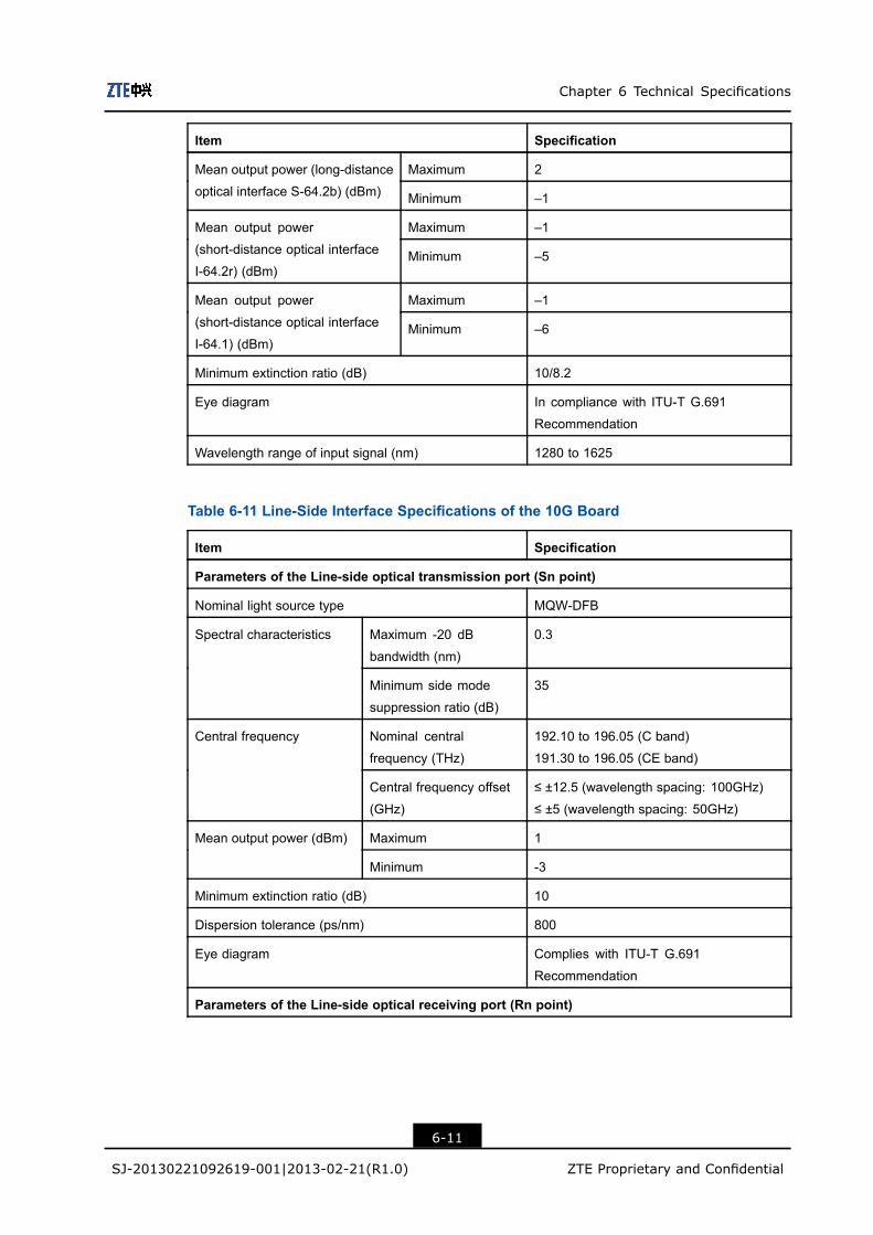
Chapter 6 Technical Specifications
Item Specification
Maximum 2Mean output power (long-distance
optical interface S-64.2b) (dBm) Minimum –1
Maximum –1Mean output power
(short-distance optical interface
I-64.2r) (dBm)Minimum –5
Maximum –1Mean output power
(short-distance optical interface
I-64.1) (dBm)Minimum –6
Minimum extinction ratio (dB) 10/8.2
Eye diagram In compliance with ITU-T G.691
Recommendation
Wavelength range of input signal (nm) 1280 to 1625
Table 6-11 Line-Side Interface Specifications of the 10G Board
Item Specification
Parameters of the Line-side optical transmission port (Sn point)
Nominal light source type MQW-DFB
Maximum -20 dB
bandwidth (nm)
0.3Spectral characteristics
Minimum side mode
suppression ratio (dB)
35
Nominal central
frequency (THz)
192.10 to 196.05 (C band)
191.30 to 196.05 (CE band)
Central frequency
Central frequency offset
(GHz)
≤ ±12.5 (wavelength spacing: 100GHz)
≤ ±5 (wavelength spacing: 50GHz)
Maximum 1Mean output power (dBm)
Minimum -3
Minimum extinction ratio (dB) 10
Dispersion tolerance (ps/nm) 800
Eye diagram Complies with ITU-T G.691
Recommendation
Parameters of the Line-side optical receiving port (Rn point)
6-11
SJ-20130221092619-001|2013-02-21(R1.0) ZTE Proprietary and Confidential
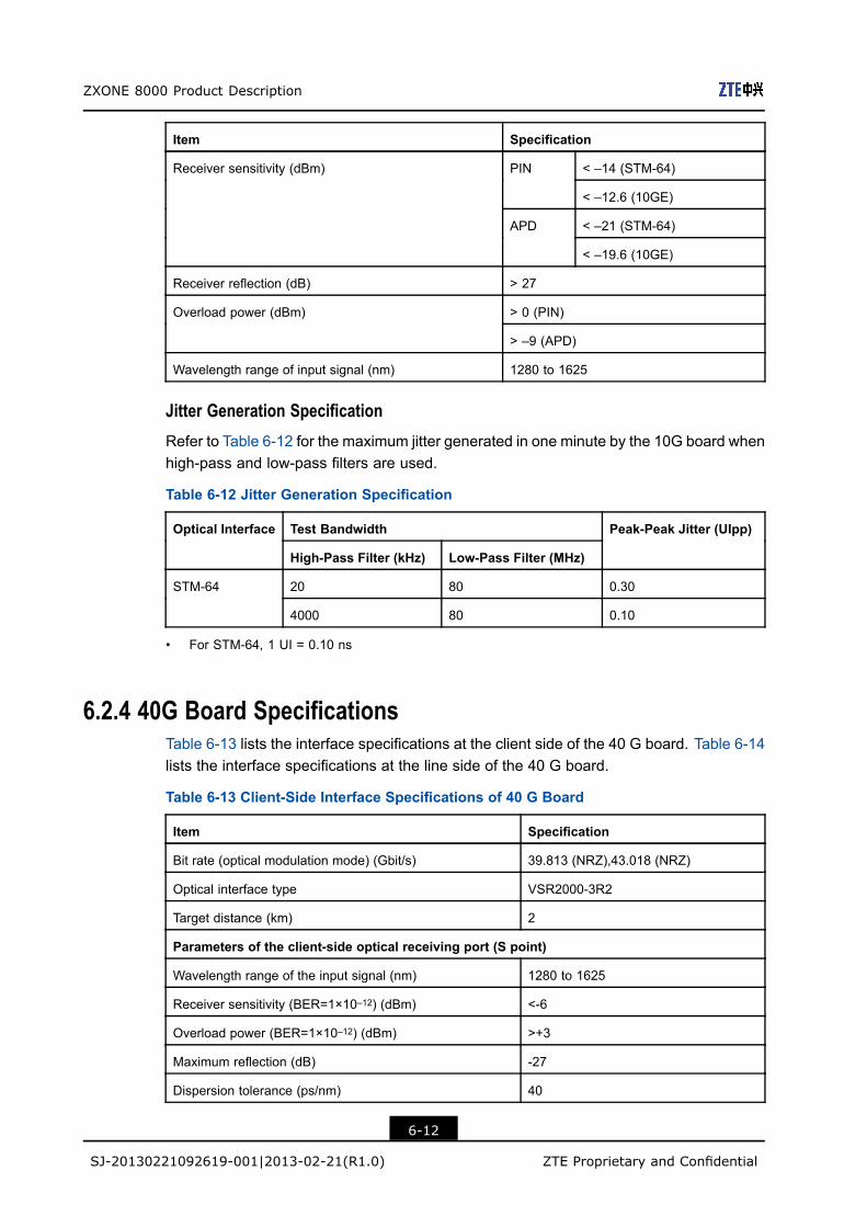
ZXONE 8000 Product Description
Item Specification
< –14 (STM-64)PIN
< –12.6 (10GE)
< –21 (STM-64)
Receiver sensitivity (dBm)
APD
< –19.6 (10GE)
Receiver reflection (dB) > 27
> 0 (PIN)Overload power (dBm)
> –9 (APD)
Wavelength range of input signal (nm) 1280 to 1625
Jitter Generation SpecificationRefer to Table 6-12 for the maximum jitter generated in one minute by the 10G board whenhigh-pass and low-pass filters are used.
Table 6-12 Jitter Generation Specification
Test BandwidthOptical Interface
High-Pass Filter (kHz) Low-Pass Filter (MHz)
Peak-Peak Jitter (UIpp)
20 80 0.30STM-64
4000 80 0.10
• For STM-64, 1 UI = 0.10 ns
6.2.4 40G Board SpecificationsTable 6-13 lists the interface specifications at the client side of the 40 G board. Table 6-14lists the interface specifications at the line side of the 40 G board.
Table 6-13 Client-Side Interface Specifications of 40 G Board
Item Specification
Bit rate (optical modulation mode) (Gbit/s) 39.813 (NRZ),43.018 (NRZ)
Optical interface type VSR2000-3R2
Target distance (km) 2
Parameters of the client-side optical receiving port (S point)
Wavelength range of the input signal (nm) 1280 to 1625
Receiver sensitivity (BER=1×10–12) (dBm) <-6
Overload power (BER=1×10–12) (dBm) >+3
Maximum reflection (dB) -27
Dispersion tolerance (ps/nm) 40
6-12
SJ-20130221092619-001|2013-02-21(R1.0) ZTE Proprietary and Confidential
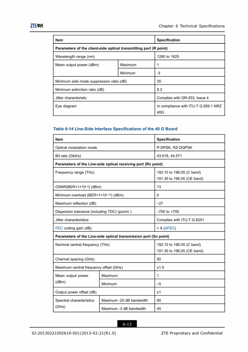
Chapter 6 Technical Specifications
Item Specification
Parameters of the client-side optical transmitting port (R point)
Wavelength range (nm) 1280 to 1625
Maximum 1Mean output power (dBm)
Minimum -3
Minimum side mode suppression ratio (dB) 35
Minimum extinction ratio (dB) 8.2
Jitter characteristic Complies with GR-253, Issue 4
Eye diagram In compliance with ITU-T G.959.1 NRZ
40G
Table 6-14 Line-Side Interface Specifications of the 40 G Board
Item Specification
Optical modulation mode P-DPSK, RZ-DQPSK
Bit rate (Gbit/s) 43.018, 44.571
Parameters of the Line-side optical receiving port (Rn point)
Frequency range (THz) 192.10 to 196.05 (C band)
191.30 to 196.05 (CE band)
OSNR(BER=1×10⁻³) (dBm) 13
Minimum overload (BER=1×10–12) (dBm) 0
Maximum reflection (dB) –27
Dispersion tolerance (including TDC) (ps/nm ) –700 to +700
Jitter characteristics Complies with ITU-T G.8251
FEC coding gain (dB) > 8 (AFEC)
Parameters of the Line-side optical transmission port (Sn point)
Nominal central frequency (THz) 192.10 to 196.05 (C band)
191.30 to 196.05 (CE band)
Channel spacing (GHz) 50
Maximum central frequency offset (GHz) ±1.5
Maximum 1Mean output power
(dBm) Minimum –5
Output power offset (dB) ±1
Maximum -20 dB bandwidth 90Spectral characteristics
(GHz) Maximum -3 dB bandwidth 45
6-13
SJ-20130221092619-001|2013-02-21(R1.0) ZTE Proprietary and Confidential

ZXONE 8000 Product Description
Item Specification
Minimum side mode suppression ratio (dB) 35
Wavelength tuning time (ms) < 30
6.2.5 100 G Board SpecificationsTable 6-15 lists the interface specifications at the client side of the 100 G board. Table6-16 lists the interface specification at the line side of the 100 G board.
Table 6-15 Client-Side Interface Specifications for the 100 G Board
Item Specification
Bit rate (optical modulation mode)
(Gbit/s)
100 GE 4 x 25.78
OTU4 4 x 27.95
100GE 4 x 25.78
OTU4 4 x 27.95
Optical interface type LR4 ER4
Target distance (km) 10 40
Parameters of the client-side optical receiving port (S point)
Wavelength range of the input signal
(nm)
1294.53 to 1296.59
1299.02 to 1301.09
1303.54 to 1305.63
1308.09 to 1310.19
Sensitivity (BER=1×10–12) (dBm) –8.6 –21.4
Overload power (BER=1×10–12)
(dBm)
> +4.5 > +4.5
Maximum reflection (dB) < –27 < –27
Parameters of client-side optical transmitting port (R point)
Wavelength range (nm) 1280 to 1625
Maximum +4.5 +2.9Mean output
power (dBm) Minimum –4.3 –2.9
Minimum extinction ratio (dB) 8 dB
Table 6-16 Line-Side Interface Specifications of the 100 G Board
Item Specification
Optical modulation mode P-DPSK, RZ-DQPSK
Bit rate (Gbit/s) 43.018, 44.571
Frequency range (THz) 192.10 to 196.05 (C band)
191.30 to 196.05 (CE band)
6-14
SJ-20130221092619-001|2013-02-21(R1.0) ZTE Proprietary and Confidential

Chapter 6 Technical Specifications
Item Specification
Parameters of the Line-side optical receiving port (Rn point)
Back-to-back OSNR (BER=1×10⁻³) (dBm) 13
Minimum overload (BER=1×10–12) (dBm) 0
Maximum reflection (dBm) –27
Dispersion tolerance (including TDC) (ps/nm ) –50000 to 50000
Polarization mode dispersion (PMD) (ps ) 30
Parameters of the Line-side optical transmission port (Sn point)
Nominal central frequency (THz) 192.10 to 196.05 (C band)
191.30 to 196.05 (CE band)
Channel spacing (GHz) 50
Maximum central frequency offset (GHz) ±1.5
Maximum 0Mean output power (dBm)
Minimum –5
Output power offset (dB) ±1
Maximum –3 dB
bandwidth (GHz)
20Spectral characteristics
Maximum –15 dB
bandwidth (GHz)
60
Minimum side mode
suppression ratio (dB)
35
Maximum reflection (dB) –27
6.3 Optical Mux/DeMux Subsystem Specifications
6.3.1 SOAD Board SpecificationsFor the technical specifications of the SOAD2 board, refer to Table 6-17. For the technicalspecifications of the SOAD4 board, refer to Table 6-18.
Table 6-17 Technical Specifications of the SOAD2 Board
Item Specification
Central frequency range (THz) 192.10 to 196.05 (C band)
191.30 to 196.05 (CE band)
Add/drop channel quantity 2
–1 dB bandwidth (Drop) (nm) > 0.2
6-15
SJ-20130221092619-001|2013-02-21(R1.0) ZTE Proprietary and Confidential
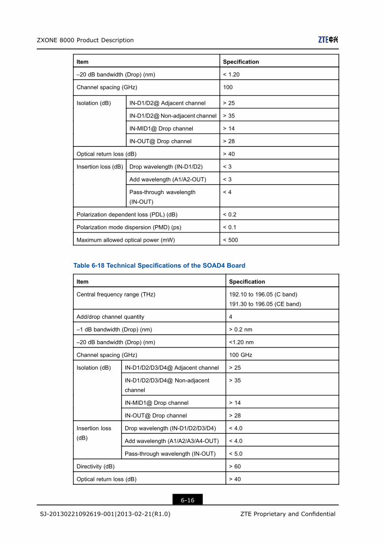
ZXONE 8000 Product Description
Item Specification
–20 dB bandwidth (Drop) (nm) < 1.20
Channel spacing (GHz) 100
IN-D1/D2@ Adjacent channel > 25
IN-D1/D2@Non-adjacent channel > 35
IN-MID1@ Drop channel > 14
Isolation (dB)
IN-OUT@ Drop channel > 28
Optical return loss (dB) > 40
Drop wavelength (IN-D1/D2) < 3
Add wavelength (A1/A2-OUT) < 3
Insertion loss (dB)
Pass-through wavelength
(IN-OUT)
< 4
Polarization dependent loss (PDL) (dB) < 0.2
Polarization mode dispersion (PMD) (ps) < 0.1
Maximum allowed optical power (mW) < 500
Table 6-18 Technical Specifications of the SOAD4 Board
Item Specification
Central frequency range (THz) 192.10 to 196.05 (C band)
191.30 to 196.05 (CE band)
Add/drop channel quantity 4
–1 dB bandwidth (Drop) (nm) > 0.2 nm
–20 dB bandwidth (Drop) (nm) <1.20 nm
Channel spacing (GHz) 100 GHz
IN-D1/D2/D3/D4@ Adjacent channel > 25
IN-D1/D2/D3/D4@ Non-adjacent
channel
> 35
IN-MID1@ Drop channel > 14
Isolation (dB)
IN-OUT@ Drop channel > 28
Drop wavelength (IN-D1/D2/D3/D4) < 4.0
Add wavelength (A1/A2/A3/A4-OUT) < 4.0
Insertion loss
(dB)
Pass-through wavelength (IN-OUT) < 5.0
Directivity (dB) > 60
Optical return loss (dB) > 40
6-16
SJ-20130221092619-001|2013-02-21(R1.0) ZTE Proprietary and Confidential
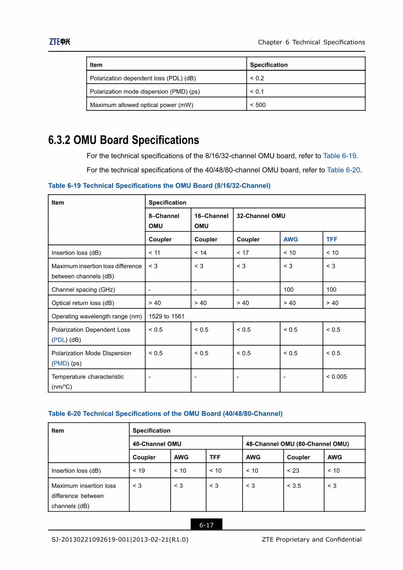
Chapter 6 Technical Specifications
Item Specification
Polarization dependent loss (PDL) (dB) < 0.2
Polarization mode dispersion (PMD) (ps) < 0.1
Maximum allowed optical power (mW) < 500
6.3.2 OMU Board SpecificationsFor the technical specifications of the 8/16/32-channel OMU board, refer to Table 6-19.
For the technical specifications of the 40/48/80-channel OMU board, refer to Table 6-20.
Table 6-19 Technical Specifications the OMU Board (8/16/32-Channel)
Specification
8–ChannelOMU
16–ChannelOMU
32-Channel OMU
Item
Coupler Coupler Coupler AWG TFF
Insertion loss (dB) < 11 < 14 < 17 < 10 < 10
Maximum insertion loss difference
between channels (dB)
< 3 < 3 < 3 < 3 < 3
Channel spacing (GHz) - - - 100 100
Optical return loss (dB) > 40 > 40 > 40 > 40 > 40
Operating wavelength range (nm) 1529 to 1561
Polarization Dependent Loss
(PDL) (dB)
< 0.5 < 0.5 < 0.5 < 0.5 < 0.5
Polarization Mode Dispersion
(PMD) (ps)
< 0.5 < 0.5 < 0.5 < 0.5 < 0.5
Temperature characteristic
(nm/℃)
- - - - < 0.005
Table 6-20 Technical Specifications of the OMU Board (40/48/80-Channel)
Specification
40-Channel OMU 48-Channel OMU (80-Channel OMU)
Item
Coupler AWG TFF AWG Coupler AWG
Insertion loss (dB) < 19 < 10 < 10 < 10 < 23 < 10
Maximum insertion loss
difference between
channels (dB)
< 3 < 3 < 3 < 3 < 3.5 < 3
6-17
SJ-20130221092619-001|2013-02-21(R1.0) ZTE Proprietary and Confidential
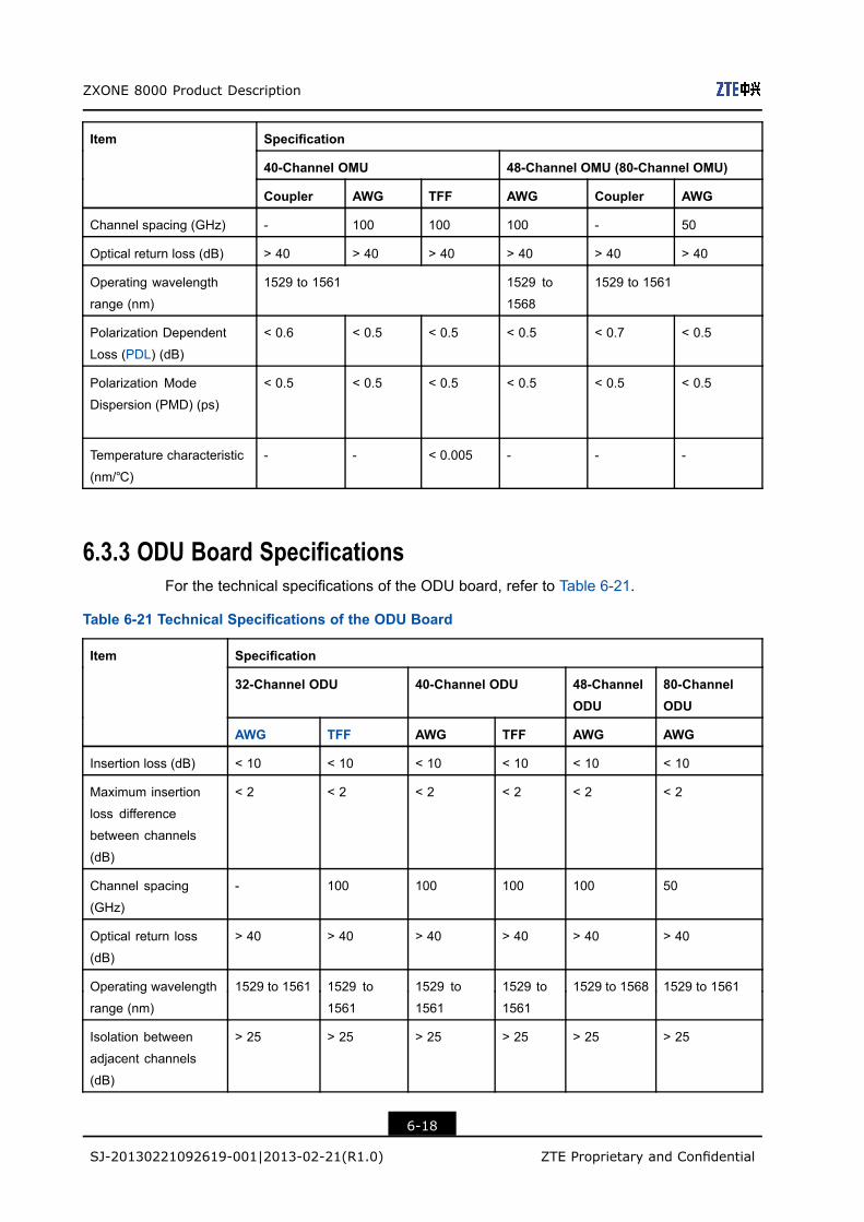
ZXONE 8000 Product Description
Specification
40-Channel OMU 48-Channel OMU (80-Channel OMU)
Item
Coupler AWG TFF AWG Coupler AWG
Channel spacing (GHz) - 100 100 100 - 50
Optical return loss (dB) > 40 > 40 > 40 > 40 > 40 > 40
Operating wavelength
range (nm)
1529 to 1561 1529 to
1568
1529 to 1561
Polarization Dependent
Loss (PDL) (dB)
< 0.6 < 0.5 < 0.5 < 0.5 < 0.7 < 0.5
Polarization Mode
Dispersion (PMD) (ps)
< 0.5 < 0.5 < 0.5 < 0.5 < 0.5 < 0.5
Temperature characteristic
(nm/℃)
- - < 0.005 - - -
6.3.3 ODU Board SpecificationsFor the technical specifications of the ODU board, refer to Table 6-21.
Table 6-21 Technical Specifications of the ODU Board
Specification
32-Channel ODU 40-Channel ODU 48-ChannelODU
80-ChannelODU
Item
AWG TFF AWG TFF AWG AWG
Insertion loss (dB) < 10 < 10 < 10 < 10 < 10 < 10
Maximum insertion
loss difference
between channels
(dB)
< 2 < 2 < 2 < 2 < 2 < 2
Channel spacing
(GHz)
- 100 100 100 100 50
Optical return loss
(dB)
> 40 > 40 > 40 > 40 > 40 > 40
Operating wavelength
range (nm)
1529 to 1561 1529 to
1561
1529 to
1561
1529 to
1561
1529 to 1568 1529 to 1561
Isolation between
adjacent channels
(dB)
> 25 > 25 > 25 > 25 > 25 > 25
6-18
SJ-20130221092619-001|2013-02-21(R1.0) ZTE Proprietary and Confidential
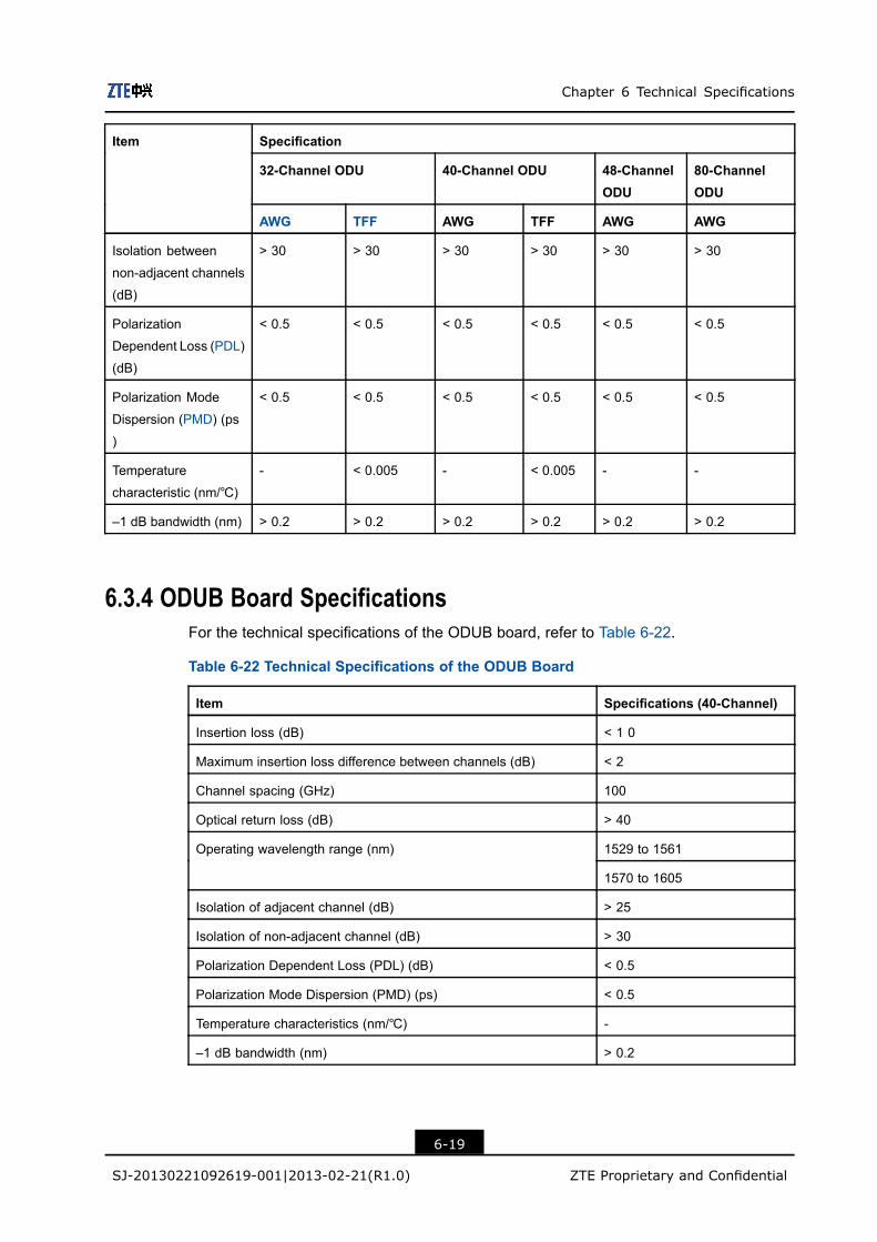
Chapter 6 Technical Specifications
Specification
32-Channel ODU 40-Channel ODU 48-ChannelODU
80-ChannelODU
Item
AWG TFF AWG TFF AWG AWG
Isolation between
non-adjacent channels
(dB)
> 30 > 30 > 30 > 30 > 30 > 30
Polarization
Dependent Loss (PDL)
(dB)
< 0.5 < 0.5 < 0.5 < 0.5 < 0.5 < 0.5
Polarization Mode
Dispersion (PMD) (ps
)
< 0.5 < 0.5 < 0.5 < 0.5 < 0.5 < 0.5
Temperature
characteristic (nm/℃)
- < 0.005 - < 0.005 - -
–1 dB bandwidth (nm) > 0.2 > 0.2 > 0.2 > 0.2 > 0.2 > 0.2
6.3.4 ODUB Board SpecificationsFor the technical specifications of the ODUB board, refer to Table 6-22.
Table 6-22 Technical Specifications of the ODUB Board
Item Specifications (40-Channel)
Insertion loss (dB) < 1 0
Maximum insertion loss difference between channels (dB) < 2
Channel spacing (GHz) 100
Optical return loss (dB) > 40
1529 to 1561Operating wavelength range (nm)
1570 to 1605
Isolation of adjacent channel (dB) > 25
Isolation of non-adjacent channel (dB) > 30
Polarization Dependent Loss (PDL) (dB) < 0.5
Polarization Mode Dispersion (PMD) (ps) < 0.5
Temperature characteristics (nm/℃) -
–1 dB bandwidth (nm) > 0.2
6-19
SJ-20130221092619-001|2013-02-21(R1.0) ZTE Proprietary and Confidential
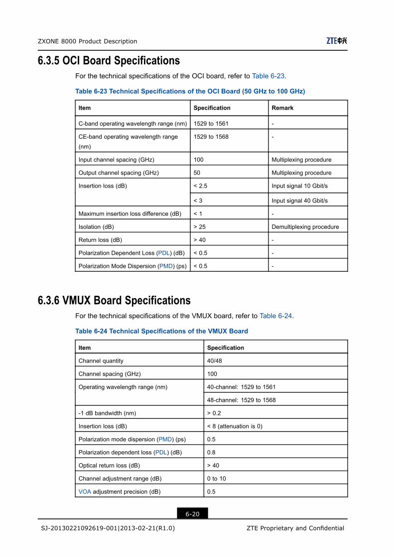
ZXONE 8000 Product Description
6.3.5 OCI Board SpecificationsFor the technical specifications of the OCI board, refer to Table 6-23.
Table 6-23 Technical Specifications of the OCI Board (50 GHz to 100 GHz)
Item Specification Remark
C-band operating wavelength range (nm) 1529 to 1561 -
CE-band operating wavelength range
(nm)
1529 to 1568 -
Input channel spacing (GHz) 100 Multiplexing procedure
Output channel spacing (GHz) 50 Multiplexing procedure
< 2.5 Input signal 10 Gbit/sInsertion loss (dB)
< 3 Input signal 40 Gbit/s
Maximum insertion loss difference (dB) < 1 -
Isolation (dB) > 25 Demultiplexing procedure
Return loss (dB) > 40 -
Polarization Dependent Loss (PDL) (dB) < 0.5 -
Polarization Mode Dispersion (PMD) (ps) < 0.5 -
6.3.6 VMUX Board SpecificationsFor the technical specifications of the VMUX board, refer to Table 6-24.
Table 6-24 Technical Specifications of the VMUX Board
Item Specification
Channel quantity 40/48
Channel spacing (GHz) 100
40-channel: 1529 to 1561Operating wavelength range (nm)
48-channel: 1529 to 1568
-1 dB bandwidth (nm) > 0.2
Insertion loss (dB) < 8 (attenuation is 0)
Polarization mode dispersion (PMD) (ps) 0.5
Polarization dependent loss (PDL) (dB) 0.8
Optical return loss (dB) > 40
Channel adjustment range (dB) 0 to 10
VOA adjustment precision (dB) 0.5
6-20
SJ-20130221092619-001|2013-02-21(R1.0) ZTE Proprietary and Confidential
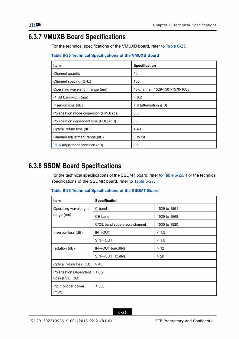
Chapter 6 Technical Specifications
6.3.7 VMUXB Board SpecificationsFor the technical specifications of the VMUXB board, refer to Table 6-25.
Table 6-25 Technical Specifications of the VMUXB Board
Item Specification
Channel quantity 40
Channel spacing (GHz) 100
Operating wavelength range (nm) 40-channel: 1529-1561/1570-1605
-1 dB bandwidth (nm) > 0.2
Insertion loss (dB) < 8 (attenuation is 0)
Polarization mode dispersion (PMD) (ps) 0.5
Polarization dependent loss (PDL) (dB) 0.8
Optical return loss (dB) > 40
Channel adjustment range (dB) 0 to 10
VOA adjustment precision (dB) 0.5
6.3.8 SSDM Board SpecificationsFor the technical specifications of the SSDMT board, refer to Table 6-26. For the technicalspecifications of the SSDMR board, refer to Table 6-27.
Table 6-26 Technical Specifications of the SSDMT Board
Item Specification
C band 1529 to 1561
CE band 1529 to 1568
Operating wavelength
range (nm)
C/CE band supervisory channel 1500 to 1520
IN→OUT < 1.5Insertion loss (dB)
SIN→OUT < 1.5
IN→OUT (@λSIN) > 12Isolation (dB)
SIN→OUT (@λIN) > 20
Optical return loss (dB) > 40
Polarization Dependent
Loss (PDL) (dB)
< 0.2
Input optical power
(mW)
< 500
6-21
SJ-20130221092619-001|2013-02-21(R1.0) ZTE Proprietary and Confidential
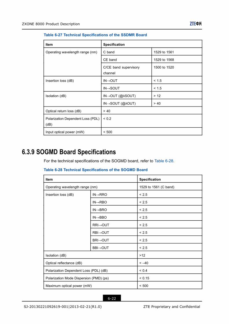
ZXONE 8000 Product Description
Table 6-27 Technical Specifications of the SSDMR Board
Item Specification
C band 1529 to 1561
CE band 1529 to 1568
Operating wavelength range (nm)
C/CE band supervisory
channel
1500 to 1520
IN→OUT < 1.5Insertion loss (dB)
IN→SOUT < 1.5
IN→OUT (@λSOUT) > 12Isolation (dB)
IN→SOUT (@λOUT) > 40
Optical return loss (dB) > 40
Polarization Dependent Loss (PDL)
(dB)
< 0.2
Input optical power (mW) < 500
6.3.9 SOGMD Board SpecificationsFor the technical specifications of the SOGMD board, refer to Table 6-28.
Table 6-28 Technical Specifications of the SOGMD Board
Item Specification
Operating wavelength range (nm) 1529 to 1561 (C band)
IN→RRO < 2.5
IN→RBO < 2.5
IN→BRO < 2.5
IN→BBO < 2.5
RRI→OUT < 2.5
RBI→OUT < 2.5
BRI→OUT < 2.5
Insertion loss (dB)
BBI→OUT < 2.5
Isolation (dB) >12
Optical reflectance (dB) < –40
Polarization Dependent Loss (PDL) (dB) < 0.4
Polarization Mode Dispersion (PMD) (ps) < 0.15
Maximum optical power (mW) < 500
6-22
SJ-20130221092619-001|2013-02-21(R1.0) ZTE Proprietary and Confidential

Chapter 6 Technical Specifications
6.3.10 WBU Board SpecificationsFor the technical specifications of the WBU board, refer to Table 6-29.
Table 6-29 Technical Specifications of the WBU Board
Item Specification
1529 to 1561 (C band)Operating wavelength range (nm)
1529 to 1568 (CE band)
100Channel spacing (GHz)
50
40/48 (channel spacing: 100 GHz)Channel quantity
80/96 (channel spacing: 50 GHz)
A1-OUT < 2
IN-D1 < 4
EXIN-OUT < 14
Insertion loss of
WBU/AD1 (dB)
IN-EXOUT < 4
A1-OUT < 12
A2-OUT < 2
IN-D1 < 12
IN-D2 < 2
EXIN-OUT < 18
Insertion loss of
WBU/AD2 (dB)
IN-EXOUT 12
Attenuation adjustment range (dB) 0 to 15
Attenuation adjustment precision (dB) < (0.5 or ±10% of the configured value, select
the larger one)
Blocking extinction ratio (dB) > 35
Return loss (dB) > 40
Maximum total optical input power (dBm) ≤ 25
Maximum single-channel optical input power
(dBm)
≤ 16
6.3.11 WSU Board SpecificationsThere are two types of WSU boards: WSUD board and WSUA board.
For the technical specifications of the WSUD board, refer to Table 6-30.
6-23
SJ-20130221092619-001|2013-02-21(R1.0) ZTE Proprietary and Confidential
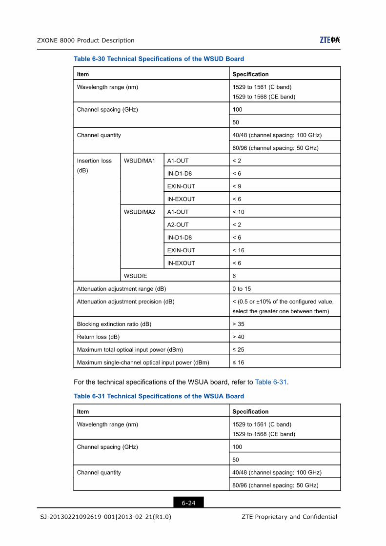
ZXONE 8000 Product Description
Table 6-30 Technical Specifications of the WSUD Board
Item Specification
Wavelength range (nm) 1529 to 1561 (C band)
1529 to 1568 (CE band)
100Channel spacing (GHz)
50
40/48 (channel spacing: 100 GHz)Channel quantity
80/96 (channel spacing: 50 GHz)
A1-OUT < 2
IN-D1-D8 < 6
EXIN-OUT < 9
WSUD/MA1
IN-EXOUT < 6
A1-OUT < 10
A2-OUT < 2
IN-D1-D8 < 6
EXIN-OUT < 16
WSUD/MA2
IN-EXOUT < 6
Insertion loss
(dB)
WSUD/E 6
Attenuation adjustment range (dB) 0 to 15
Attenuation adjustment precision (dB) < (0.5 or ±10% of the configured value,
select the greater one between them)
Blocking extinction ratio (dB) > 35
Return loss (dB) > 40
Maximum total optical input power (dBm) ≤ 25
Maximum single-channel optical input power (dBm) ≤ 16
For the technical specifications of the WSUA board, refer to Table 6-31.
Table 6-31 Technical Specifications of the WSUA Board
Item Specification
Wavelength range (nm) 1529 to 1561 (C band)
1529 to 1568 (CE band)
100Channel spacing (GHz)
50
40/48 (channel spacing: 100 GHz)Channel quantity
80/96 (channel spacing: 50 GHz)
6-24
SJ-20130221092619-001|2013-02-21(R1.0) ZTE Proprietary and Confidential
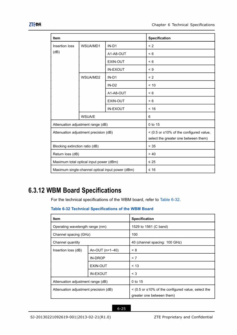
Chapter 6 Technical Specifications
Item Specification
IN-D1 < 2
A1-A8-OUT < 6
EXIN-OUT < 6
WSUA/MD1
IN-EXOUT < 9
IN-D1 < 2
IN-D2 < 10
A1-A8-OUT < 6
EXIN-OUT < 6
WSUA/MD2
IN-EXOUT < 16
Insertion loss
(dB)
WSUA/E 6
Attenuation adjustment range (dB) 0 to 15
Attenuation adjustment precision (dB) < (0.5 or ±10% of the configured value,
select the greater one between them)
Blocking extinction ratio (dB) > 35
Return loss (dB) > 40
Maximum total optical input power (dBm) ≤ 25
Maximum single-channel optical input power (dBm) ≤ 16
6.3.12 WBM Board SpecificationsFor the technical specifications of the WBM board, refer to Table 6-32.
Table 6-32 Technical Specifications of the WBM Board
Item Specification
Operating wavelength range (nm) 1529 to 1561 (C band)
Channel spacing (GHz) 100
Channel quantity 40 (channel spacing: 100 GHz)
An-OUT (n=1–40) < 8
IN-DROP < 7
EXIN-OUT < 13
Insertion loss (dB)
IN-EXOUT < 3
Attenuation adjustment range (dB) 0 to 15
Attenuation adjustment precision (dB) < (0.5 or ±10% of the configured value, select the
greater one between them)
6-25
SJ-20130221092619-001|2013-02-21(R1.0) ZTE Proprietary and Confidential

ZXONE 8000 Product Description
Item Specification
Return loss (dB) > 40
6.3.13 PDU Board SpecificationsFor the technical specifications of the PDU-4-x board, refer to Table 6-33. For the technicalspecifications of the PDU-5-x board, refer to Table 6-34. For the technical specificationsof the PDU-8-x board, refer to Table 6-35. For the technical specifications of the PDU-9-xboard, refer to Table 6-36. For the technical specifications of the PDU-16-1 board, refer toTable 6-37.
Table 6-33 Technical Specifications for the PDU-4-x Board
Item Specification
Operating wavelength range (nm) 1529 to 1561 (C band)
1529 to 1568 (CE band)
Insertion loss (dB) INx→Ox-1/2/3/4 < 8.0
Polarization dependent loss (PDL) (dB) < 0.4
Return loss (dB) > 40
Table 6-34 Technical Specifications for the PDU-5-x Board
Item Specification
Operating wavelength range (nm) 1529 to 1561 (C band)
1529 to 1568 (CE band)
INx→Ox-1/2/3/4 < 12.0Insertion loss (dB)
INx→Dx < 4.0
Polarization dependent loss (PDL) (dB) < 0.5
Return loss (dB) > 40
Table 6-35 Technical Specifications for the PDU-8-x Board
Item Specification
Operating wavelength range (nm) 1529 to 1561 (C band)
1529 to 1568 (CE band)
Insertion loss (dB) INx→Ox-1/2/3/4/5/6/7/8 < 11.0
Polarization dependent loss (PDL) (dB) < 0.5
Return loss (dB) > 40
6-26
SJ-20130221092619-001|2013-02-21(R1.0) ZTE Proprietary and Confidential

Chapter 6 Technical Specifications
Table 6-36 Technical Specifications for the PDU-9-x Board
Item Specification
Operating wavelength range (nm) 1529 to 1561 (C band)
1529 to 1568 (CE band)
INx→Ox-1/2/3/4/5/6/7/8 < 15.0Insertion loss (dB)
INx→Dx < 4.0
Polarization dependent loss (PDL) (dB) < 0.5
Return loss (dB) > 40
Table 6-37 Technical Specifications for the PDU-16-x Board
Item Specification
Operating wavelength range (nm) 1529 to 1561 (C band)
1529 to 1568 (CE band)
Insertion loss (dB) IN→O-1/2/3/4/5/6/7/8
/9/10/11/12/13/14/15/16
< 14.0
Polarization dependent loss (PDL) (dB) < 0.5
Return loss (dB) > 40
6.4 Optical Amplification Subsystem Specifications
6.4.1 SEOA Board Specifications
SEOBA Board Specifications
For the technical specifications of the SEOBA board with 40/80-channel in the C band,refer to Table 6-38.
Table 6-38 Technical Specifications of the 40/80-Channel C-Band SEOBA Board
Specification (40/80-Channel)
SEOBA17/17 SEOBA22/20
Item
40-Channel 80-Channel 40-Channel 80-Channel
Operating wavelength range (nm) 1529 to 1561 1529 to 1561
Total input power range (dBm) –32 to 0 –32 to –2
Channel input power range (dBm) –32 to –16 –32 to –19 –32 to –18 –32 to –21
Total output power range (dBm) –2 to 17 –5 to 17 1 to 20 –2 to 20
6-27
SJ-20130221092619-001|2013-02-21(R1.0) ZTE Proprietary and Confidential

ZXONE 8000 Product Description
Specification (40/80-Channel)
SEOBA17/17 SEOBA22/20
Item
40-Channel 80-Channel 40-Channel 80-Channel
Maximum total output power
(dBm)
17 20
Noise figure (dB) < 6 < 6
Polarization Dependent Loss
(PDL) (dB)
< 0.5 < 0.5
Pump leakage at input (dBm) < –30 < –30
Pump leakage at output (dBm) < –30 < –30
Input return loss (dB) > 40 > 40
Output return loss (dB) > 40 > 40
Nominal gain (dB) 17 22
Maximum allowed input
reflectance (dB)
> 30 > 30
Maximum allowed output
reflectance (dB)
> 30 > 30
Gain flatness (dB) ±1 ±1
Gain response time while
adding/reducing channels (stable
status) (ms)
< 10 < 10
Polarization Mode Dispersion
(PMD) (ps)
< 0.5 < 0.5
SEOPA Board Specifications
For the technical specifications of the SEOPA board with 40/80-channel in the C band,refer to Table 6-39.
Table 6-39 Technical Specifications of the 40/80-Channel C-Band SEOPA Board
Specification (40/80-Channel)
SEOPA17/17 SEOPA22/17 SEOPA27/17
Item
40-Cha-nnel
80-Cha-nnel
40-Cha-nnel
80-Chan-nel
40-Chan-nel
80-Chan-nel
Operating wavelength
range (nm)
1529 to 1561 1529 to 1561 1529 to 1561
Total input power range
(dBm)
–35 to 0 –35 to –4 –35 to –10
6-28
SJ-20130221092619-001|2013-02-21(R1.0) ZTE Proprietary and Confidential

Chapter 6 Technical Specifications
Specification (40/80-Channel)
SEOPA17/17 SEOPA22/17 SEOPA27/17
Item
40-Cha-nnel
80-Cha-nnel
40-Cha-nnel
80-Chan-nel
40-Chan-nel
80-Chan-nel
Channel input power
range (dBm)
–35 to
–16
–35 to
–19
–35 to
–20
–35 to –23 –35 to –26 –35 to –29
Total output power range
(dBm)
–2 to 17 –5 to 17 –2 to 17 –5 to 17 –2 to 17 –5 to 17
Maximum total output
power (dBm)
17 17 17
Noise figure (dB) < 5.5 < 5.5 < 5.5
Polarization Dependent
Loss (PDL) (dB)
< 0.5 < 0.5 < 0.5
Pump leakage at input
(dBm)
< –30 < –30 < –30
Pump leakage at output
(dBm)
< –30 < –30 < –30
Input return loss (dB) > 40 > 40 > 40
Output return loss (dB) > 40 > 40 > 40
Nominal gain (dB) 17 22 27
Maximum allowed input
reflectance (dB)
> 30 > 30 > 30
Maximum allowed output
reflectance (dB)
> 30 > 30 > 30
Gain flatness (dB) ±1 ±1 ±1
Gain response time while
adding/reducing channels
(stable status) (ms)
< 10 < 10 < 10
Polarization Mode
Dispersion (PMD) (ps)
< 0.5 < 0.5 < 0.5
SEOLA Board Specifications
For the technical specifications of the SEOLA board with 40/80-channel in the C band,refer to Table 6-40.
6-29
SJ-20130221092619-001|2013-02-21(R1.0) ZTE Proprietary and Confidential
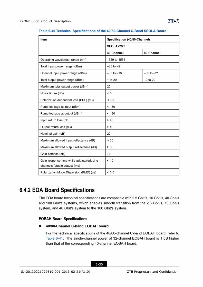
ZXONE 8000 Product Description
Table 6-40 Technical Specifications of the 40/80-Channel C-Band SEOLA Board
Specification (40/80-Channel)
SEOLA22/20
Item
40-Channel 80-Channel
Operating wavelength range (nm) 1529 to 1561
Total input power range (dBm) –35 to –2
Channel input power range (dBm) –35 to –18 –35 to –21
Total output power range (dBm) 1 to 20 –2 to 20
Maximum total output power (dBm) 20
Noise figure (dB) < 6
Polarization dependent loss (PDL) (dB) < 0.5
Pump leakage at input (dBm) < –30
Pump leakage at output (dBm) < –30
Input return loss (dB) > 40
Output return loss (dB) > 40
Nominal gain (dB) 22
Maximum allowed input reflectance (dB) > 30
Maximum allowed output reflectance (dB) > 30
Gain flatness (dB) ±1
Gain response time while adding/reducing
channels (stable status) (ms)
< 10
Polarization Mode Dispersion (PMD) (ps) < 0.5
6.4.2 EOA Board SpecificationsThe EOA board technical specifications are compatible with 2.5 Gbit/s, 10 Gbit/s, 40 Gbit/sand 100 Gbit/s systems, which enables smooth transition from the 2.5 Gbit/s, 10 Gbit/ssystem, and 40 Gbit/s system to the 100 Gbit/s system.
EOBAH Board Specifications
l 40/80-Channel C-band EOBAH board
For the technical specifications of the 40/80-channel C-band EOBAH board, refer toTable 6-41. The single-channel power of 32-channel EOBAH board is 1 dB higherthan that of the corresponding 40-channel EOBAH board.
6-30
SJ-20130221092619-001|2013-02-21(R1.0) ZTE Proprietary and Confidential
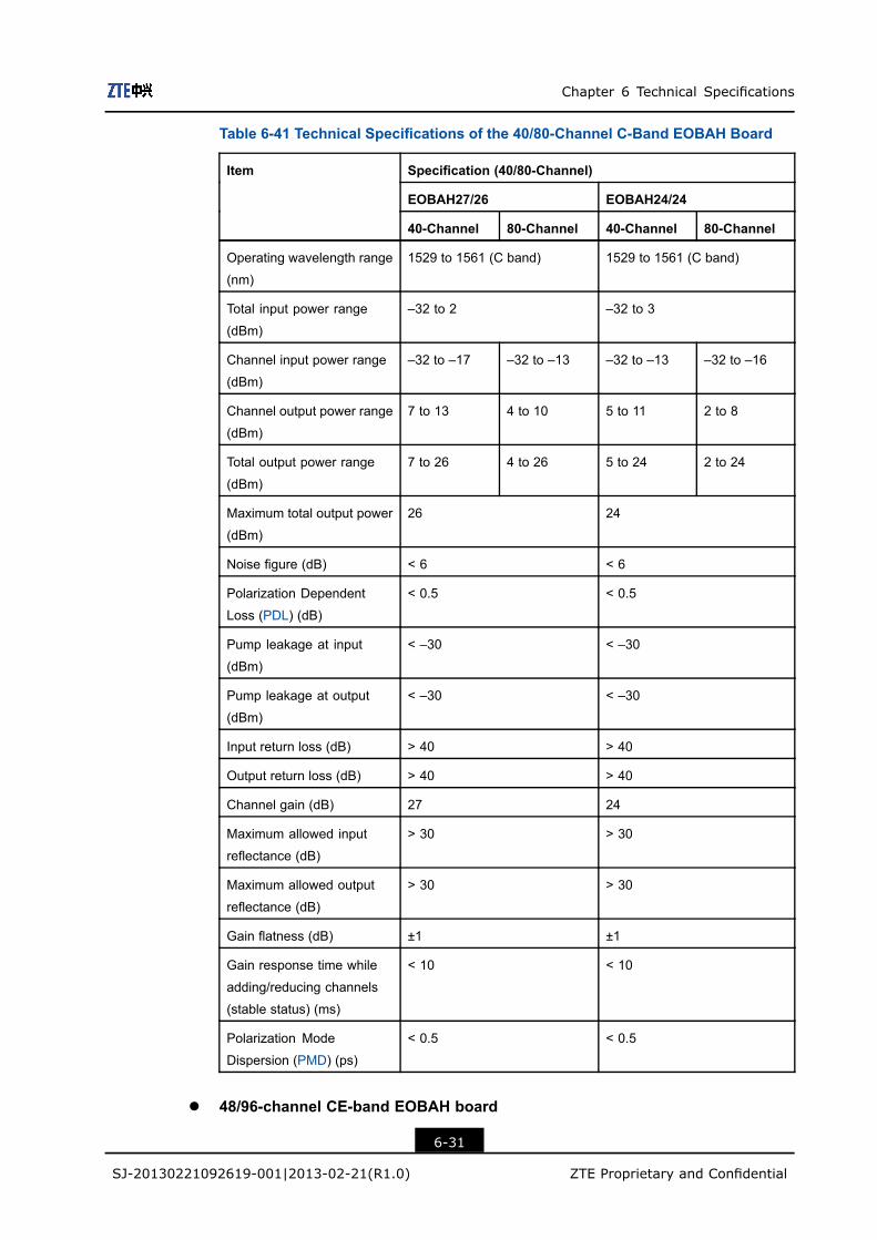
Chapter 6 Technical Specifications
Table 6-41 Technical Specifications of the 40/80-Channel C-Band EOBAH Board
Specification (40/80-Channel)
EOBAH27/26 EOBAH24/24
Item
40-Channel 80-Channel 40-Channel 80-Channel
Operating wavelength range
(nm)
1529 to 1561 (C band) 1529 to 1561 (C band)
Total input power range
(dBm)
–32 to 2 –32 to 3
Channel input power range
(dBm)
–32 to –17 –32 to –13 –32 to –13 –32 to –16
Channel output power range
(dBm)
7 to 13 4 to 10 5 to 11 2 to 8
Total output power range
(dBm)
7 to 26 4 to 26 5 to 24 2 to 24
Maximum total output power
(dBm)
26 24
Noise figure (dB) < 6 < 6
Polarization Dependent
Loss (PDL) (dB)
< 0.5 < 0.5
Pump leakage at input
(dBm)
< –30 < –30
Pump leakage at output
(dBm)
< –30 < –30
Input return loss (dB) > 40 > 40
Output return loss (dB) > 40 > 40
Channel gain (dB) 27 24
Maximum allowed input
reflectance (dB)
> 30 > 30
Maximum allowed output
reflectance (dB)
> 30 > 30
Gain flatness (dB) ±1 ±1
Gain response time while
adding/reducing channels
(stable status) (ms)
< 10 < 10
Polarization Mode
Dispersion (PMD) (ps)
< 0.5 < 0.5
l 48/96-channel CE-band EOBAH board
6-31
SJ-20130221092619-001|2013-02-21(R1.0) ZTE Proprietary and Confidential
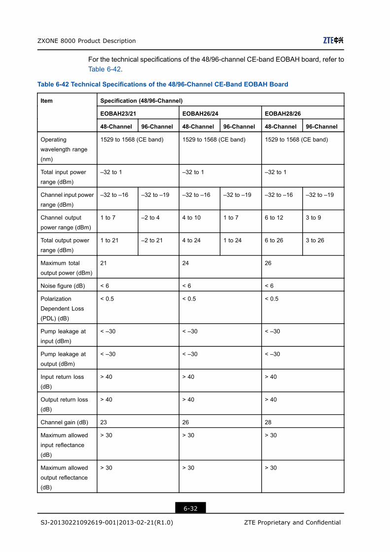
ZXONE 8000 Product Description
For the technical specifications of the 48/96-channel CE-band EOBAH board, refer toTable 6-42.
Table 6-42 Technical Specifications of the 48/96-Channel CE-Band EOBAH Board
Specification (48/96-Channel)
EOBAH23/21 EOBAH26/24 EOBAH28/26
Item
48-Channel 96-Channel 48-Channel 96-Channel 48-Channel 96-Channel
Operating
wavelength range
(nm)
1529 to 1568 (CE band) 1529 to 1568 (CE band) 1529 to 1568 (CE band)
Total input power
range (dBm)
–32 to 1 –32 to 1 –32 to 1
Channel input power
range (dBm)
–32 to –16 –32 to –19 –32 to –16 –32 to –19 –32 to –16 –32 to –19
Channel output
power range (dBm)
1 to 7 –2 to 4 4 to 10 1 to 7 6 to 12 3 to 9
Total output power
range (dBm)
1 to 21 –2 to 21 4 to 24 1 to 24 6 to 26 3 to 26
Maximum total
output power (dBm)
21 24 26
Noise figure (dB) < 6 < 6 < 6
Polarization
Dependent Loss
(PDL) (dB)
< 0.5 < 0.5 < 0.5
Pump leakage at
input (dBm)
< –30 < –30 < –30
Pump leakage at
output (dBm)
< –30 < –30 < –30
Input return loss
(dB)
> 40 > 40 > 40
Output return loss
(dB)
> 40 > 40 > 40
Channel gain (dB) 23 26 28
Maximum allowed
input reflectance
(dB)
> 30 > 30 > 30
Maximum allowed
output reflectance
(dB)
> 30 > 30 > 30
6-32
SJ-20130221092619-001|2013-02-21(R1.0) ZTE Proprietary and Confidential
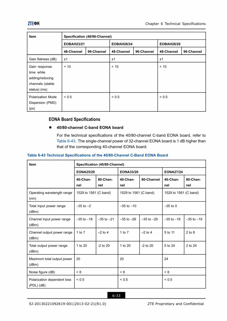
Chapter 6 Technical Specifications
Specification (48/96-Channel)
EOBAH23/21 EOBAH26/24 EOBAH28/26
Item
48-Channel 96-Channel 48-Channel 96-Channel 48-Channel 96-Channel
Gain flatness (dB) ±1 ±1 ±1
Gain response
time while
adding/reducing
channels (stable
status) (ms)
< 10 < 10 < 10
Polarization Mode
Dispersion (PMD)
(ps)
< 0.5 < 0.5 < 0.5
EONA Board Specifications
l 40/80-channel C-band EONA board
For the technical specifications of the 40/80-channel C-band EONA board, refer toTable 6-43. The single-channel power of 32-channel EONA board is 1 dB higher thanthat of the corresponding 40-channel EONA board.
Table 6-43 Technical Specifications of the 40/80-Channel C-Band EONA Board
Specification (40/80-Channel)
EONA25/20 EONA33/20 EONA27/24
Item
40-Chan-nel
80-Chan-nel
40-Chan-nel
80-Channel 40-Chan-nel
80-Chan-nel
Operating wavelength range
(nm)
1529 to 1561 (C band) 1529 to 1561 (C band) 1529 to 1561 (C band)
Total input power range
(dBm)
–35 to –2 –35 to –10 –35 to 0
Channel input power range
(dBm)
–35 to –18 –35 to –21 –35 to –26 –35 to –29 –35 to –16 –35 to –19
Channel output power range
(dBm)
1 to 7 –2 to 4 1 to 7 –2 to 4 5 to 11 2 to 8
Total output power range
(dBm)
1 to 20 -2 to 20 1 to 20 -2 to 20 5 to 24 2 to 24
Maximum total output power
(dBm)
20 20 24
Noise figure (dB) < 6 < 6 < 6
Polarization dependent loss
(PDL) (dB)
< 0.5 < 0.5 < 0.5
6-33
SJ-20130221092619-001|2013-02-21(R1.0) ZTE Proprietary and Confidential
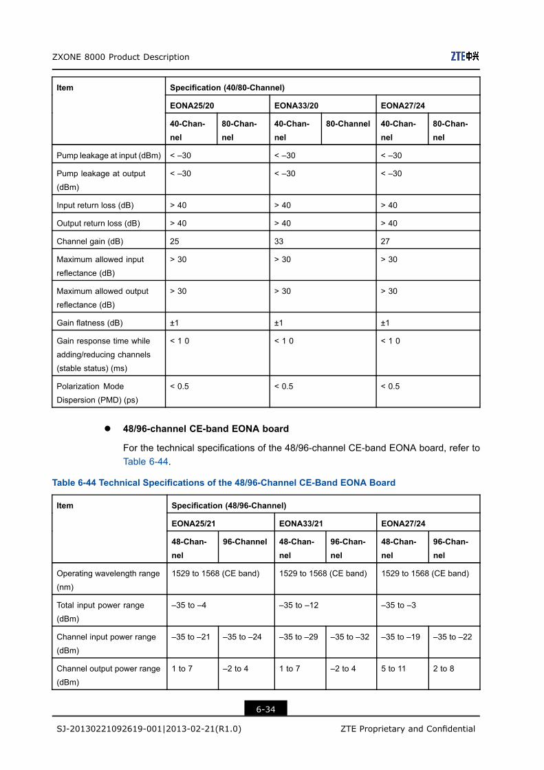
ZXONE 8000 Product Description
Specification (40/80-Channel)
EONA25/20 EONA33/20 EONA27/24
Item
40-Chan-nel
80-Chan-nel
40-Chan-nel
80-Channel 40-Chan-nel
80-Chan-nel
Pump leakage at input (dBm) < –30 < –30 < –30
Pump leakage at output
(dBm)
< –30 < –30 < –30
Input return loss (dB) > 40 > 40 > 40
Output return loss (dB) > 40 > 40 > 40
Channel gain (dB) 25 33 27
Maximum allowed input
reflectance (dB)
> 30 > 30 > 30
Maximum allowed output
reflectance (dB)
> 30 > 30 > 30
Gain flatness (dB) ±1 ±1 ±1
Gain response time while
adding/reducing channels
(stable status) (ms)
< 1 0 < 1 0 < 1 0
Polarization Mode
Dispersion (PMD) (ps)
< 0.5 < 0.5 < 0.5
l 48/96-channel CE-band EONA board
For the technical specifications of the 48/96-channel CE-band EONA board, refer toTable 6-44.
Table 6-44 Technical Specifications of the 48/96-Channel CE-Band EONA Board
Specification (48/96-Channel)
EONA25/21 EONA33/21 EONA27/24
Item
48-Chan-nel
96-Channel 48-Chan-nel
96-Chan-nel
48-Chan-nel
96-Chan-nel
Operating wavelength range
(nm)
1529 to 1568 (CE band) 1529 to 1568 (CE band) 1529 to 1568 (CE band)
Total input power range
(dBm)
–35 to –4 –35 to –12 –35 to –3
Channel input power range
(dBm)
–35 to –21 –35 to –24 –35 to –29 –35 to –32 –35 to –19 –35 to –22
Channel output power range
(dBm)
1 to 7 –2 to 4 1 to 7 –2 to 4 5 to 11 2 to 8
6-34
SJ-20130221092619-001|2013-02-21(R1.0) ZTE Proprietary and Confidential
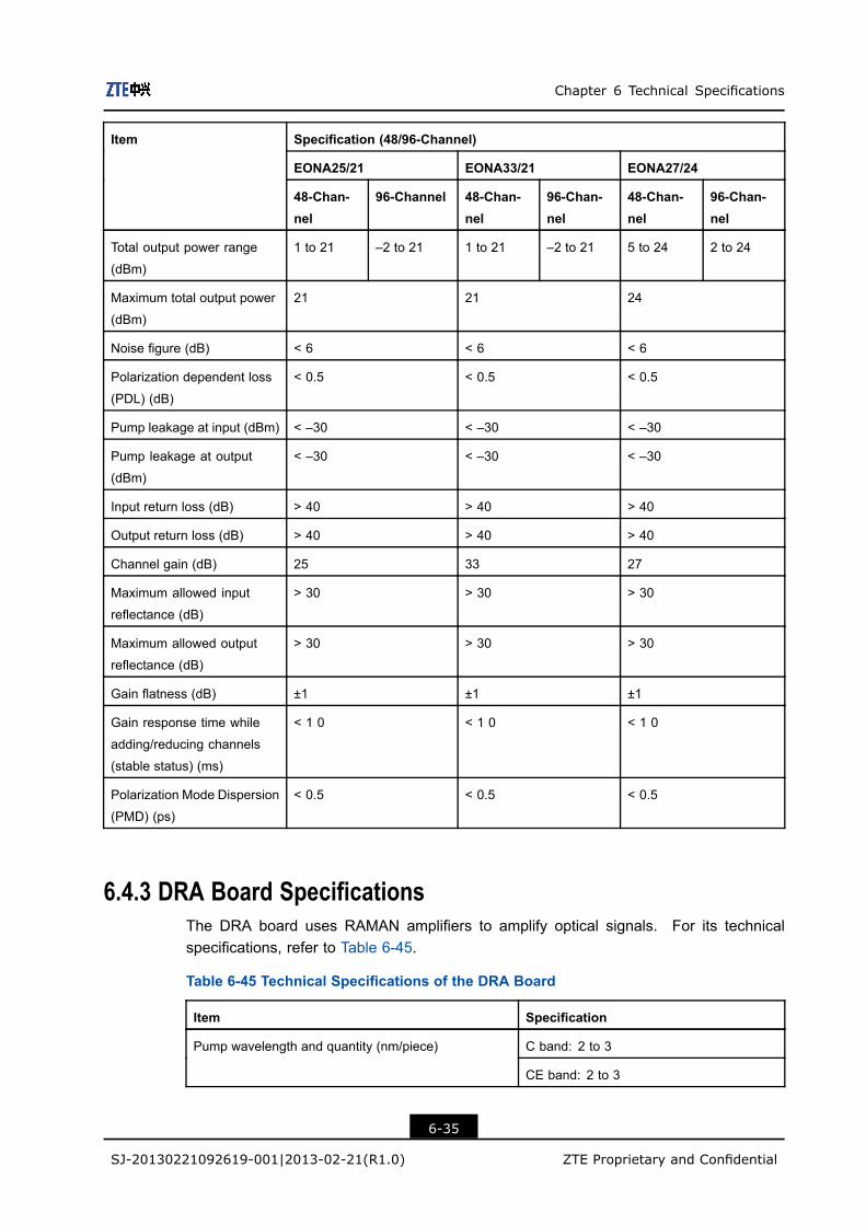
Chapter 6 Technical Specifications
Specification (48/96-Channel)
EONA25/21 EONA33/21 EONA27/24
Item
48-Chan-nel
96-Channel 48-Chan-nel
96-Chan-nel
48-Chan-nel
96-Chan-nel
Total output power range
(dBm)
1 to 21 –2 to 21 1 to 21 –2 to 21 5 to 24 2 to 24
Maximum total output power
(dBm)
21 21 24
Noise figure (dB) < 6 < 6 < 6
Polarization dependent loss
(PDL) (dB)
< 0.5 < 0.5 < 0.5
Pump leakage at input (dBm) < –30 < –30 < –30
Pump leakage at output
(dBm)
< –30 < –30 < –30
Input return loss (dB) > 40 > 40 > 40
Output return loss (dB) > 40 > 40 > 40
Channel gain (dB) 25 33 27
Maximum allowed input
reflectance (dB)
> 30 > 30 > 30
Maximum allowed output
reflectance (dB)
> 30 > 30 > 30
Gain flatness (dB) ±1 ±1 ±1
Gain response time while
adding/reducing channels
(stable status) (ms)
< 1 0 < 1 0 < 1 0
Polarization Mode Dispersion
(PMD) (ps)
< 0.5 < 0.5 < 0.5
6.4.3 DRA Board SpecificationsThe DRA board uses RAMAN amplifiers to amplify optical signals. For its technicalspecifications, refer to Table 6-45.
Table 6-45 Technical Specifications of the DRA Board
Item Specification
C band: 2 to 3Pump wavelength and quantity (nm/piece)
CE band: 2 to 3
6-35
SJ-20130221092619-001|2013-02-21(R1.0) ZTE Proprietary and Confidential

ZXONE 8000 Product Description
Item Specification
Pump power (dBm) ≥ 29
Total output power (dBm) ≥ 12
C/CE band gain (G.652) (dB) 10/10
C/CE band gain (LEAF) (dB) 12/12
C/CE band gain (TW RS) (dB) 13/13
C/CE band equivalent noise figure (G.652) (dB) 0/0
C/CE band equivalent noise figure (LEAF) (dB) –1/–1
C/CE band equivalent noise figure (TW RS) (dB) –1.5/–1.5
Polarization dependent gain (dB) < 0.5
Temperature stability (pm/℃) < 500
In actual application, both EDFA and RAMAN amplifiers are used to amplify optical signals,meaning the EOA and DRA boards combine to amplify optical signals. The technicalspecifications for the combination of EOA and DRA boards are listed in Table 6-46.
Table 6-46 Technical Specifications of the EOA and DRA Board Combination
Item Specification
1529 to 1561 (C band)Operating wavelength range (nm)
1529 to 1568 (CE band)
Maximum total output power (dBm) 20
Noise figure (dB) < 3
Polarization Dependent Loss (PDL) (dB) < 0.5
Pump leakage at output (dBm) < –30
Input return loss (dB) > 40
Output return loss (dB) > 40
Maximum allowed input reflectance (dB) > 30
Maximum allowed output reflectance (dB) > 30
Gain flatness (dB) ±1
Gain response time while adding/reducing channels
(stable status) (ms)
< 1 0
Polarization mode dispersion (PMD) (ps) < 0.5
6.4.4 LAC Board SpecificationsFor the technical specifications of the LAC board, refer to Table 6-47.
6-36
SJ-20130221092619-001|2013-02-21(R1.0) ZTE Proprietary and Confidential

Chapter 6 Technical Specifications
Table 6-47 Technical Specifications of the LAC Board
Item Unit Specification
1529 to 1561 (C band)Wavelength range (band) (nm) nm
1529 to 1568 (CE band)
Optical input power detection range (dBm) dBm –39 to +20
Optical output power detection range (dBm) dBm –40 to +18
Optical power detection precision (dB) dB ≤ ±0.5
Attenuation adjustment precision (dB) dB ≤ ±0.5
Attenuation adjustment step length (dB) dB ≤ ±0.2
Attenuation adjustment range (dB) dB ≥ 20
Attenuation adjustment rate (dB/s) dB/s ≤ 10
6.5 Optical Layer Management SubsystemSpecifications
6.5.1 OPM Board SpecificationsFor the technical specifications of the OPM board with channel spacing of 50 GHz, referto Table 6-48. For the technical specifications of the OPM board with channel spacing of100 GHz, refer to Table 6-49.
Table 6-48 Technical Specifications of the OPM Board (50 GHz)
Item Specification
1529 to 1561 (C band)Wavelength range (nm)
1529 to 1568 (CE band)
Wavelength detection precision (nm) ±0.05
Input power range (dBm) –45 to –15
Power detection precision (dBm) ±1.5
OSNR range (dB) ≤ 25
OSNR detection precision (dB) ±1.5
Input return loss (dB) 30
6-37
SJ-20130221092619-001|2013-02-21(R1.0) ZTE Proprietary and Confidential

ZXONE 8000 Product Description
Table 6-49 Technical Specifications of the OPM Board (100 GHz)
Item Specification
1529 to 1561 (C band)Wavelength range (nm)
1529 to 1568 (CE band)
Wavelength detection precision (nm) ±0.1
Input power range (dBm) –45 to –15
Power detection precision (dBm) ±1.5
OSNR range (dB) ≤ 25
OSNR detection precision (dB) ±1.5
Input return loss (dB) 30
6.5.2 EOPM Board SpecificationsFor the technical specifications of the EOPM board with channel spacing of 50 GHz, referto Table 6-50. For the technical specifications of the EOPM board with channel spacing of100 GHz, refer to Table 6-51.
Table 6-50 Technical Specifications of the EOPM Board (50 GHz)
Item Specification
1529 to 1561 (C band)
1570 to 1605 (L band)
Wavelength range (nm)
1529 to 1568 (CE band)
Wavelength detection range (nm) ±0.05
Input power range (dBm) –45 to –15
Power detection precision (dBm) ±1.5
OSNR range (dB) ≤ 25
OSNR detection precision (dB) ±1.5
Input return loss (dB) 30
Signal detection time (s) ≤ 1
Table 6-51 Technical Specifications of the EOPM Board (100 GHz)
Item Specification
1529 to 1561 (C band)
1570 to 1605 (L band)
Wavelength range (nm)
1529 to 1568 (CE band)
6-38
SJ-20130221092619-001|2013-02-21(R1.0) ZTE Proprietary and Confidential
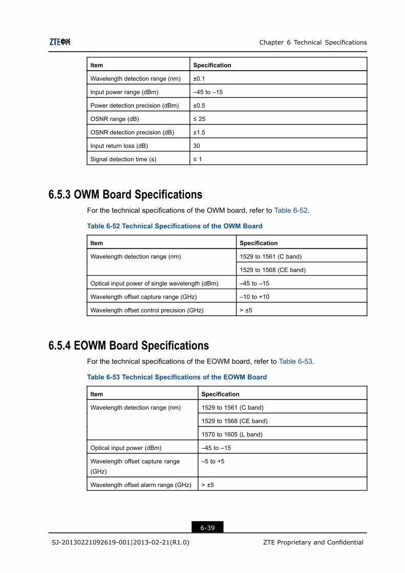
Chapter 6 Technical Specifications
Item Specification
Wavelength detection range (nm) ±0.1
Input power range (dBm) –45 to –15
Power detection precision (dBm) ±0.5
OSNR range (dB) ≤ 25
OSNR detection precision (dB) ±1.5
Input return loss (dB) 30
Signal detection time (s) ≤ 1
6.5.3 OWM Board SpecificationsFor the technical specifications of the OWM board, refer to Table 6-52.
Table 6-52 Technical Specifications of the OWM Board
Item Specification
1529 to 1561 (C band)Wavelength detection range (nm)
1529 to 1568 (CE band)
Optical input power of single wavelength (dBm) –45 to –15
Wavelength offset capture range (GHz) –10 to +10
Wavelength offset control precision (GHz) > ±5
6.5.4 EOWM Board SpecificationsFor the technical specifications of the EOWM board, refer to Table 6-53.
Table 6-53 Technical Specifications of the EOWM Board
Item Specification
1529 to 1561 (C band)
1529 to 1568 (CE band)
Wavelength detection range (nm)
1570 to 1605 (L band)
Optical input power (dBm) –45 to –15
Wavelength offset capture range
(GHz)
–5 to +5
Wavelength offset alarm range (GHz) > ±5
6-39
SJ-20130221092619-001|2013-02-21(R1.0) ZTE Proprietary and Confidential

ZXONE 8000 Product Description
6.6 Protection Subsystem Specifications
6.6.1 SOP Board SpecificationsFor the technical specifications of the SOP board, refer to Table 6-54.
Table 6-54 Technical Specifications of the SOP Board
Item Specification
1280 to 1625Operating wavelength Range (nm)
1510 to 1625 1280 to 1510
T1_I→T1_O1 < 4.4 < 5.0
T2_I→T2_O1 < 4.4 < 5.0
T1_I→T1_O2 < 4.4 < 5.0
T2_I→T2_O2 < 4.4 < 5.0
R1_I1→ R1_O < 2.1 < 2.7
R2_I1→ R2_O < 2.1 < 2.7
R1_I2→ R1_O < 2.1 < 2.7
Insertion Loss (dB)
R2_I2→ R2_O < 2.1 < 2.7
Return loss (dB) > 40
Polarization dependent loss (dB) < 0.2
Optical input power (mW) < 200
Switching time (ms) 50
6.6.2 SOPCS Board SpecificationsFor the technical specifications of the SOPCS board, refer to Table 6-55.
Table 6-55 Technical Specifications of the SOPCS Board
Item Specification
Operating wavelength range (nm) 1260 to 1620 1510 to 1620 1260 to 1510
6-40
SJ-20130221092619-001|2013-02-21(R1.0) ZTE Proprietary and Confidential
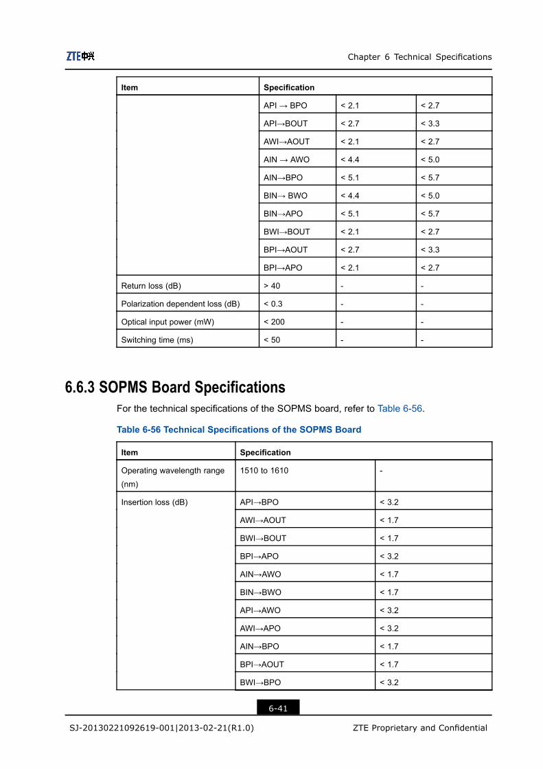
Chapter 6 Technical Specifications
Item Specification
API → BPO < 2.1 < 2.7
API→BOUT < 2.7 < 3.3
AWI→AOUT < 2.1 < 2.7
AIN → AWO < 4.4 < 5.0
AIN→BPO < 5.1 < 5.7
BIN→ BWO < 4.4 < 5.0
BIN→APO < 5.1 < 5.7
BWI→BOUT < 2.1 < 2.7
BPI→AOUT < 2.7 < 3.3
BPI→APO < 2.1 < 2.7
Return loss (dB) > 40 - -
Polarization dependent loss (dB) < 0.3 - -
Optical input power (mW) < 200 - -
Switching time (ms) < 50 - -
6.6.3 SOPMS Board SpecificationsFor the technical specifications of the SOPMS board, refer to Table 6-56.
Table 6-56 Technical Specifications of the SOPMS Board
Item Specification
Operating wavelength range
(nm)
1510 to 1610 -
API→BPO < 3.2
AWI→AOUT < 1.7
BWI→BOUT < 1.7
BPI→APO < 3.2
AIN→AWO < 1.7
BIN→BWO < 1.7
API→AWO < 3.2
AWI→APO < 3.2
AIN→BPO < 1.7
BPI→AOUT < 1.7
BWI→BPO < 3.2
Insertion loss (dB)
6-41
SJ-20130221092619-001|2013-02-21(R1.0) ZTE Proprietary and Confidential
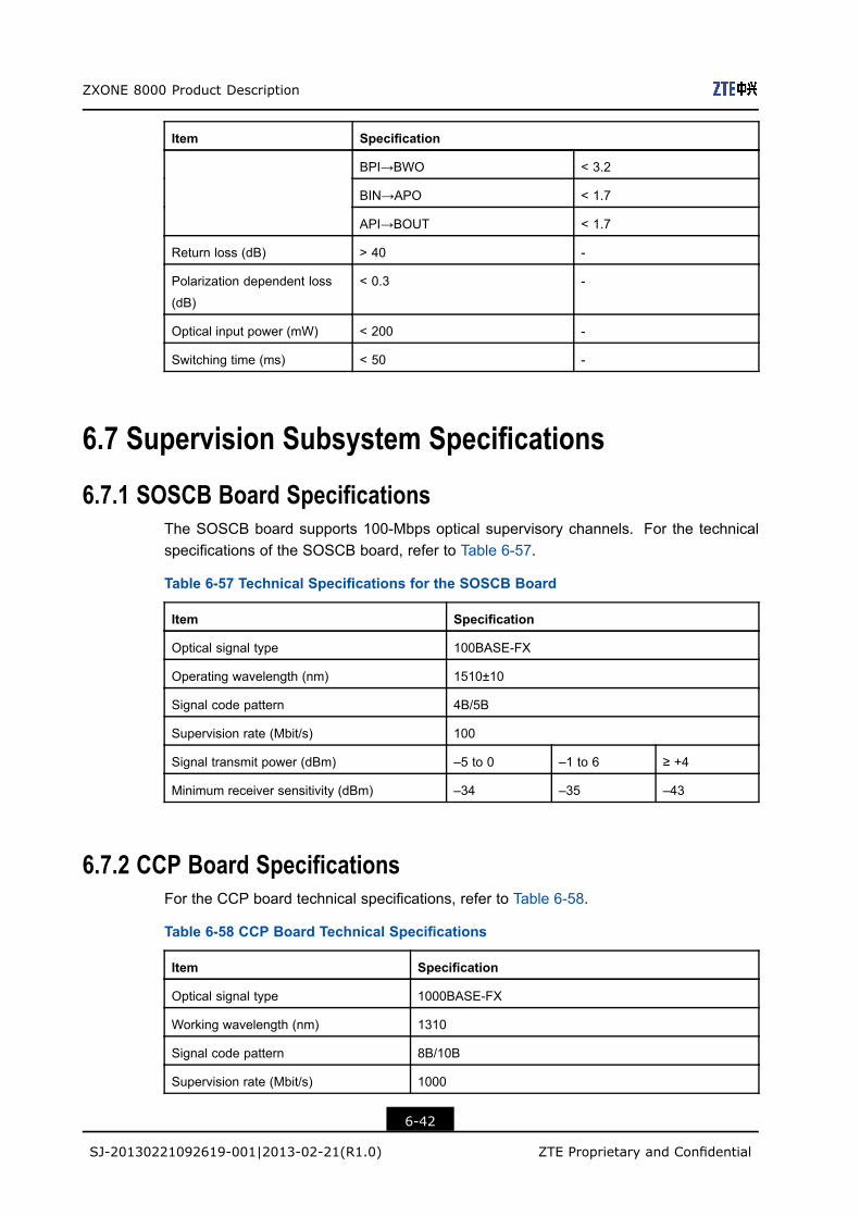
ZXONE 8000 Product Description
Item Specification
BPI→BWO < 3.2
BIN→APO < 1.7
API→BOUT < 1.7
Return loss (dB) > 40 -
Polarization dependent loss
(dB)
< 0.3 -
Optical input power (mW) < 200 -
Switching time (ms) < 50 -
6.7 Supervision Subsystem Specifications
6.7.1 SOSCB Board SpecificationsThe SOSCB board supports 100-Mbps optical supervisory channels. For the technicalspecifications of the SOSCB board, refer to Table 6-57.
Table 6-57 Technical Specifications for the SOSCB Board
Item Specification
Optical signal type 100BASE-FX
Operating wavelength (nm) 1510±10
Signal code pattern 4B/5B
Supervision rate (Mbit/s) 100
Signal transmit power (dBm) –5 to 0 –1 to 6 ≥ +4
Minimum receiver sensitivity (dBm) –34 –35 –43
6.7.2 CCP Board SpecificationsFor the CCP board technical specifications, refer to Table 6-58.
Table 6-58 CCP Board Technical Specifications
Item Specification
Optical signal type 1000BASE-FX
Working wavelength (nm) 1310
Signal code pattern 8B/10B
Supervision rate (Mbit/s) 1000
6-42
SJ-20130221092619-001|2013-02-21(R1.0) ZTE Proprietary and Confidential

Chapter 6 Technical Specifications
Item Specification
Optical signal transmit power (dBm) -8`-2 ±3
Minimum receiver sensitivity (dBm) –20
6.8 RPOA Subsystem Specifications
6.8.1 Applicable Transmission CodesThe RPOA subsystem is designed for ultra-long-haul transmission. It only supports thetransmission over a single span because the Signal-to-Noise Ratio (SNR) of the systemdecreases greatly if fibers are too long.
Because the amplification range of the EDF does not include 1510-nm wavelength and thesupervisory information cannot be transmitted over a long distance, the RPOA subsystemneeds an independent service wavelength to transfer supervision signals.
Table 6-59 describes the transmission codes supported by RPOA subsystem over a singlespan. Note that the system capacity listed in the table already includes a supervisorychannel.
Table 6-59 Transmission Codes Supported by the RPOA Subsystem (over a SingleSpan)
Fiber Type Single-Span Line Attenuation (dB) Maximum System Capacity(Gbit/s)
≤ 73 4 × 2.5
≤ 72 8 × 2.5
≤ 69 16 × 2.5
≤ 63 40 × 2.5
≤ 67 4 × 10
≤ 67 8 × 10
≤ 67 16 × 10
G.652 fiber
≤ 63 40 × 10
6-43
SJ-20130221092619-001|2013-02-21(R1.0) ZTE Proprietary and Confidential

ZXONE 8000 Product Description
Fiber Type Single-Span Line Attenuation (dB) Maximum System Capacity(Gbit/s)
≤ 68.5 4 × 2.5
≤ 67 8 × 2.5
≤ 64 16 × 2.5
≤ 63 40 × 2.5
≤ 66 4 × 10
≤ 66 8 × 10
≤ 66 16 × 10
G.655 fiber
≤ 63 40 × 10
6.8.2 RPOA Subsystem Optical SpecificationsFor the RPOA subsystem optical specifications, refer to Table 6-60.
Table 6-60 RPOA Subsystem Optical Specifications
Item RPOA Subsystem with a GFF RPOA Subsystem without GFF
Amplification range (nm) 1529 to 1561 1546 to 1561
Noise figure (dB) < 7 (within the amplification range) < 7 (within the amplification range)
Gain (dB) > 17 > 17
Gain flatness (dB) < 2 < 2
Optical input power (dBm) -44 to -18 -44 to -18
Optical output power (dBm) -30 to +2 -34 to 8
Operating temperature
range (°C)
-40 to 65 (RGU), -10 to 60 (RPU) -40 to 65 (RGU), -10 to 60 (RPU)
Storage temperature range
(°C)
-40 to 85 -40 to 85
• The RPOA subsystem without Gain Flatness Filter (GFF) meets the requirements of the system with up to 16 wavelengths, while the RPOA subsystem with a GFF meets the requirements of systems with up to 40 wavelengths.
6.9 DCM Technical SpecificationsDCM optical modules are classified into two types according to different principles: DCMbased on Dispersion Compensation Fiber (DCF) and DCMs based on fiber brag grating.
For descriptions for DCM technical specifications, refer to Table 6-61 and Table 6-62.
6-44
SJ-20130221092619-001|2013-02-21(R1.0) ZTE Proprietary and Confidential
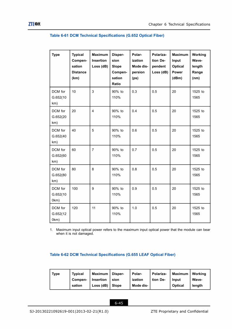
Chapter 6 Technical Specifications
Table 6-61 DCM Technical Specifications (G.652 Optical Fiber)
Type TypicalCompen-sationDistance(km)
MaximumInsertionLoss (dB)
Disper-sionSlopeCompen-sationRatio
Polar-izationMode dis-persion(ps)
Polariza-tion De-pendentLoss (dB)
MaximumInputOpticalPower(dBm)
WorkingWave-lengthRange(nm)
DCM for
G.652(10
km)
10 3 90% to
110%
0.3 0.5 20 1525 to
1565
DCM for
G.652(20
km)
20 4 90% to
110%
0.4 0.5 20 1525 to
1565
DCM for
G.652(40
km)
40 5 90% to
110%
0.6 0.5 20 1525 to
1565
DCM for
G.652(60
km)
60 7 90% to
110%
0.7 0.5 20 1525 to
1565
DCM for
G.652(80
km)
80 8 90% to
110%
0.8 0.5 20 1525 to
1565
DCM for
G.652(10
0km)
100 9 90% to
110%
0.9 0.5 20 1525 to
1565
DCM for
G.652(12
0km)
120 11 90% to
110%
1.0 0.5 20 1525 to
1565
1. Maximum input optical power refers to the maximum input optical power that the module can bearwhen it is not damaged.
Table 6-62 DCM Technical Specifications (G.655 LEAF Optical Fiber)
Type TypicalCompen-sation
MaximumInsertionLoss (dB)
Disper-sionSlope
Polar-izationMode dis-
Polariza-tion De-
MaximumInputOptical
WorkingWave-length
6-45
SJ-20130221092619-001|2013-02-21(R1.0) ZTE Proprietary and Confidential

ZXONE 8000 Product Description
Distance(km)
Compen-sationRatio
persion(ps)
pendentLoss (dB)
Power(dBm)
Range(nm)
DCM for
G.655
LEAF(20
km)
20 4 80% to
120%
0.45 0.3 20 1525 to
1565
DCM for
G.655
LEAF(40
km)
40 5 80% to
120%
0.6 0.3 20 1525 to
1565
DCM for
G.655
LEAF(60
km)
60 6 80% to
120%
0.75 0.3 20 1525 to
1565
DCM for
G.655
LEAF(80
km)
80 7 80% to
120%
0.8 0.3 20 1525 to
1565
DCM for
G.655
LEAF(100
km)
100 8 80% to
120%
0.9 0.3 20 1525 to
1565
DCM for
G.655L-
EAF(120
km)
120 9 80% to
120%
1.0 0.3 20 1525 to
1565
DCM for
G.655
LEAF
FBG(240
km)
240 4 80% to
120%
1.5 0.25 23 1528 to
1568
1. Maximum input optical power refers to the maximum input optical power that the module can bearwhen it is not damaged.
6.10 Environment SpecificationsThe environment requirements for the ZXONE 8000 equipment can be classified into threeaspects: storage environment, transportation environment, and operational environment.
6-46
SJ-20130221092619-001|2013-02-21(R1.0) ZTE Proprietary and Confidential

Chapter 6 Technical Specifications
6.10.1 Power Supply RequirementFor the power supply requirements of the ZXONE 8000 system, refer to Table 6-63.
Table 6-63 Power Supply Requirements
Input voltage: Allowable fluctuation range:
–48 VDC –60 VDC to –40 VDC
–60 VDC –70 VDC to –50 VDC
6.10.2 Storage Environment
Climate RequirementThe climate requirements for the ZXONE 8000 equipment are described in Table 6-64.
Table 6-64 Climate Requirements (Storage Environment)
Item Specifications
Altitude ≤ 4000 m
Air pressure 70 kPa to 106 kPa
Temperature –40 ℃ to +70 ℃
Temperature variance ratio ≤ 1 ℃/min
Relative humidity 5% to 100%
Solar radiation ≤ 1120 W/s2
Heat radiation ≤ 600 W/s2
Wind speed ≤ 20 m/s
Waterproof Requirement
l Keep the equipment indoors.l Ensure that there is no water on the storage room floor, so that the water will not leak
on the packing container of the equipment. Furthermore, the storage position shouldbe far away from leaking surfaces such as automatic fire fighting equipment and theheating system.
l If the equipment must be stored outside, the requirements are listed as follows:
à Ensure that the packing box of the equipment is in good condition without anydamage.
à Waterproofing measures should be taken to prevent rain from leaking into thepacking box of the equipment.
à Ensure that there is no water on the floor where the equipment is placed.
à Do not expose the packing box to direct sunlight.
6-47
SJ-20130221092619-001|2013-02-21(R1.0) ZTE Proprietary and Confidential
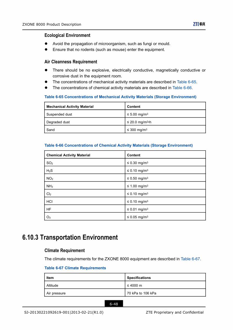
ZXONE 8000 Product Description
Ecological Environment
l Avoid the propagation of microorganism, such as fungi or mould.l Ensure that no rodents (such as mouse) enter the equipment.
Air Cleanness Requirement
l There should be no explosive, electrically conductive, magnetically conductive orcorrosive dust in the equipment room.
l The concentrations of mechanical activity materials are described in Table 6-65.l The concentrations of chemical activity materials are described in Table 6-66.
Table 6-65 Concentrations of Mechanical Activity Materials (Storage Environment)
Mechanical Activity Material Content
Suspended dust ≤ 5.00 mg/m3
Degraded dust ≤ 20.0 mg/m2•h
Sand ≤ 300 mg/m3
Table 6-66 Concentrations of Chemical Activity Materials (Storage Environment)
Chemical Activity Material Content
SO2 ≤ 0.30 mg/m3
H2S ≤ 0.10 mg/m3
NO2 ≤ 0.50 mg/m3
NH3 ≤ 1.00 mg/m3
Cl2 ≤ 0.10 mg/m3
HCI ≤ 0.10 mg/m3
HF ≤ 0.01 mg/m3
O3 ≤ 0.05 mg/m3
6.10.3 Transportation Environment
Climate Requirement
The climate requirements for the ZXONE 8000 equipment are described in Table 6-67.
Table 6-67 Climate Requirements
Item Specifications
Altitude ≤ 4000 m
Air pressure 70 kPa to 106 kPa
6-48
SJ-20130221092619-001|2013-02-21(R1.0) ZTE Proprietary and Confidential
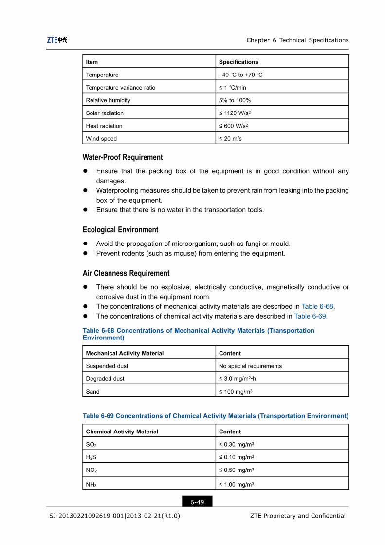
Chapter 6 Technical Specifications
Item Specifications
Temperature –40 ℃ to +70 ℃
Temperature variance ratio ≤ 1 ℃/min
Relative humidity 5% to 100%
Solar radiation ≤ 1120 W/s2
Heat radiation ≤ 600 W/s2
Wind speed ≤ 20 m/s
Water-Proof Requirement
l Ensure that the packing box of the equipment is in good condition without anydamages.
l Waterproofing measures should be taken to prevent rain from leaking into the packingbox of the equipment.
l Ensure that there is no water in the transportation tools.
Ecological Environment
l Avoid the propagation of microorganism, such as fungi or mould.l Prevent rodents (such as mouse) from entering the equipment.
Air Cleanness Requirement
l There should be no explosive, electrically conductive, magnetically conductive orcorrosive dust in the equipment room.
l The concentrations of mechanical activity materials are described in Table 6-68.l The concentrations of chemical activity materials are described in Table 6-69.
Table 6-68 Concentrations of Mechanical Activity Materials (TransportationEnvironment)
Mechanical Activity Material Content
Suspended dust No special requirements
Degraded dust ≤ 3.0 mg/m2•h
Sand ≤ 100 mg/m3
Table 6-69 Concentrations of Chemical Activity Materials (Transportation Environment)
Chemical Activity Material Content
SO2 ≤ 0.30 mg/m3
H2S ≤ 0.10 mg/m3
NO2 ≤ 0.50 mg/m3
NH3 ≤ 1.00 mg/m3
6-49
SJ-20130221092619-001|2013-02-21(R1.0) ZTE Proprietary and Confidential
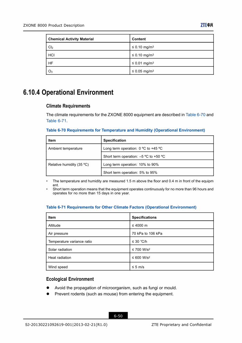
ZXONE 8000 Product Description
Chemical Activity Material Content
Cl2 ≤ 0.10 mg/m3
HCI ≤ 0.10 mg/m3
HF ≤ 0.01 mg/m3
O3 ≤ 0.05 mg/m3
6.10.4 Operational Environment
Climate Requirements
The climate requirements for the ZXONE 8000 equipment are described in Table 6-70 andTable 6-71.
Table 6-70 Requirements for Temperature and Humidity (Operational Environment)
Item Specification
Long term operation: 0 ºC to +45 ºCAmbient temperature
Short term operation: –5 ºC to +50 ºC
Long term operation: 10% to 90%Relative humidity (35 ºC)
Short term operation: 5% to 95%
• The temperature and humidity are measured 1.5 m above the floor and 0.4 m in front of the equipment.
• Short term operation means that the equipment operates continuously for no more than 96 hours andoperates for no more than 15 days in one year.
Table 6-71 Requirements for Other Climate Factors (Operational Environment)
Item Specifications
Altitude ≤ 4000 m
Air pressure 70 kPa to 106 kPa
Temperature variance ratio ≤ 30 ℃/h
Solar radiation ≤ 700 W/s2
Heat radiation ≤ 600 W/s2
Wind speed ≤ 5 m/s
Ecological Environment
l Avoid the propagation of microorganism, such as fungi or mould.l Prevent rodents (such as mouse) from entering the equipment.
6-50
SJ-20130221092619-001|2013-02-21(R1.0) ZTE Proprietary and Confidential

Chapter 6 Technical Specifications
Air Cleanness Requirement
l There should be no explosive, electrically conductive, magnetically conductive orcorrosive dust in the equipment room.
l The concentrations of mechanical activity materials are described in Table 6-72.l The concentrations of chemical activity materials are described in Table 6-73.
Table 6-72 Concentrations of Mechanical Activity Materials (Operational Environment)
Mechanical Activity Material Content
Suspended dust ≤ 0.2 mg/m3
Degraded dust ≤ 15 mg/m2•h
Sand ≤ 100 mg/m3
Dust particle ≤ 3×10⁵ /m3
Table 6-73 Concentrations of Chemical Activity Materials (Operational Environment)
Chemical Activity Material Content
SO2 ≤ 0.30 mg/m3
H2S ≤ 0.10 mg/m3
NO2 ≤ 0.50 mg/m3
NH3 ≤ 3.00 mg/m3
Cl2 ≤ 0.10 mg/m3
HCI ≤ 0.10 mg/m3
HF ≤ 0.01 mg/m3
O3 ≤ 0.05 mg/m3
NOx ≤ 0.5 mg/m3
6.11 Electro Magnetic Compatibility RequirementsElectro-Magnetic CompatibilityFor the Electro-Magnetic Compatibility (EMC) specifications of the ZXONE 8000 system,refer to Table 6-74.
Table 6-74 EMC Specifications
Test Item Standard
Electrostatic discharge immunity GB/T 17626.2 or IEC 61000-4-2
Immunity to radiation from radio
frequency electromagnetic field
GB/T 17626.3 or IEC 61000-4-3
6-51
SJ-20130221092619-001|2013-02-21(R1.0) ZTE Proprietary and Confidential
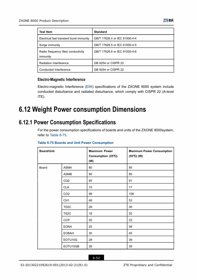
ZXONE 8000 Product Description
Test Item Standard
Electrical fast transient burst immunity GB/T 17626.4 or IEC 61000-4-4
Surge immunity GB/T 17626.5 or IEC 61000-4-5
Radio frequency filed conductivity
immunity
GB/T 17626.6 or IEC 61000-4-6
Radiation Interference GB 9254 or CISPR 22
Conducted Interference GB 9254 or CISPR 22
Electro-Magnetic Interference
Electro-magnetic Interference (EMI) specifications of the ZXONE 8000 system includeconducted disturbance and radiated disturbance, which comply with CISPR 22 (A-levelITE).
6.12 Weight Power consumption Dimensions
6.12.1 Power Consumption SpecificationsFor the power consumption specifications of boards and units of the ZXONE 8000system,refer to Table 6-75.
Table 6-75 Boards and Unit Power Consumption
Board/Unit Maximum PowerConsumption (25℃℃℃)(W)
Maximum Power Consumption(55℃℃℃) (W)
ASMA 80 85
ASMB 80 85
CQ2 85 91
CLK 15 17
CO2 98 108
CH1 48 53
TD2C 28 30
TS2C 18 20
CCP 20 23
EONA 25 38
EOBAH 30 45
EOTU10G 28 39
EOTU10GB 28 39
Board
6-52
SJ-20130221092619-001|2013-02-21(R1.0) ZTE Proprietary and Confidential
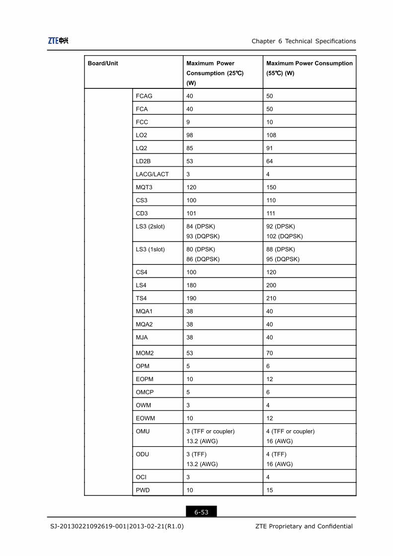
Chapter 6 Technical Specifications
Board/Unit Maximum PowerConsumption (25℃℃℃)(W)
Maximum Power Consumption(55℃℃℃) (W)
FCAG 40 50
FCA 40 50
FCC 9 10
LO2 98 108
LQ2 85 91
LD2B 53 64
LACG/LACT 3 4
MQT3 120 150
CS3 100 110
CD3 101 111
LS3 (2slot) 84 (DPSK)
93 (DQPSK)
92 (DPSK)
102 (DQPSK)
LS3 (1slot) 80 (DPSK)
86 (DQPSK)
88 (DPSK)
95 (DQPSK)
CS4 100 120
LS4 180 200
TS4 190 210
MQA1 38 40
MQA2 38 40
MJA 38 40
MOM2 53 70
OPM 5 6
EOPM 10 12
OMCP 5 6
OWM 3 4
EOWM 10 12
OMU 3 (TFF or coupler)
13.2 (AWG)
4 (TFF or coupler)
16 (AWG)
ODU 3 (TFF)
13.2 (AWG)
4 (TFF)
16 (AWG)
OCI 3 4
PWD 10 15
6-53
SJ-20130221092619-001|2013-02-21(R1.0) ZTE Proprietary and Confidential

ZXONE 8000 Product Description
Board/Unit Maximum PowerConsumption (25℃℃℃)(W)
Maximum Power Consumption(55℃℃℃) (W)
PDU 3 4
RPU 45 75
SOTU2.5G 24 27
SOTU10G 25 30
SOPCS 3 4
SOPMS 3 4
SRM42 20 30
SRM41 33 50
SOGMD 5 6
SOAD2 4 5
SOAD4 5 6
SEOBA 14 20
SEOPA 11 15
SEOLA 14 20
SSDM 4 5
SOP 5 6
SFANA 10 20
SPWA 28 55
PWE 10 11
SNP 10 12
SOSCB 17 18
SCC 10 12
TIS 15 20
ETI 11.5 12
EIC 10 8
SEIA 5 6
TST3 90 117
VMUX 30 36
VMUXB 30 36
WBU 15 18
WSU 15 18
6-54
SJ-20130221092619-001|2013-02-21(R1.0) ZTE Proprietary and Confidential

Chapter 6 Technical Specifications
Board/Unit Maximum PowerConsumption (25℃℃℃)(W)
Maximum Power Consumption(55℃℃℃) (W)
WBM 29 35
XCA 96 106
Fan plug-in box - 52 100
For typical configurations of the ZXONE 8000 system subracks and their powerconsumptions, refer to Table 6-76.
Table 6-76 Typical Configurations and Power Consummations
Subrack Typical Configuration Power Consumption (W)
CX20 XCA × 2 + CCP × 2 + LS3 × 10 + CD3 × 5 + PWD ×
2 + FCC
1594.0
CX30 CLK × 2 + XCA × 4 + CCP × 2 + LS3 × 20 + CD3 × 10 +
PWD × 4 + FCC × 2
3174.1
CX50 CLK × 2 + XCA × 6 + CCP × 4 + LO2 × 20 + CO2 × 20 +
PWD × 6 + FCC × 2
4154.7
CX51 CLK × 2 + XCA × 6 + CCP × 4 + LS4 × 15 + CS4 × 15 +
PWD × 6 + FCC × 2
4703.6
NX4 SPWA × 2 + SFANA × 4 + SEIA + SOTU10G × 26 751
DX41 PWE × 2 + CCP × 2 + FCC + SOTU10G × 28 823
1. The typical configuration of a subrack varies with the application scenarios. The power consumptionof a subrack in actual applications prevails.
6.12.2 Physical Specifications
Dimensions and WeightFor the dimensions and weight of each ZXONE 8000 system component, refer to Table6-77 and Table 6-78.
Table 6-77 Dimensions and Weight of ZXONE 8000 Components
Component Dimensions (mm) Weight (kg)
CX20 subrack 447 (H) ×535 (W) ×275 (D) 16.00
CX30 subrack 897 (H) ×535 (W) × 275 (D) 26.00
CX50 subrack 1347 (H) ×535 (W) ×275 (D) 35.00
NX4 subrack 422 (H) × 533 (W) ×286 (D) 12.50
DX41 subrack 447 (H) × 535 (W) × 275 (D) 16.00
6-55
SJ-20130221092619-001|2013-02-21(R1.0) ZTE Proprietary and Confidential
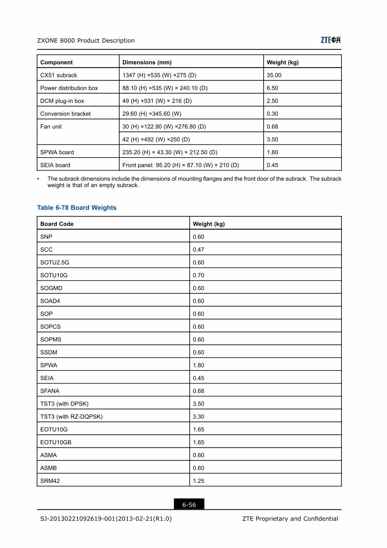
ZXONE 8000 Product Description
Component Dimensions (mm) Weight (kg)
CX51 subrack 1347 (H) ×535 (W) ×275 (D) 35.00
Power distribution box 88.10 (H) ×535 (W) × 240.10 (D) 6.50
DCM plug-in box 49 (H) ×531 (W) × 216 (D) 2.50
Conversion bracket 29.60 (H) ×345.60 (W) 0.30
30 (H) ×122.90 (W) ×276.80 (D) 0.68Fan unit
42 (H) ×492 (W) ×250 (D) 3.50
SPWA board 235.20 (H) × 43.30 (W) × 212.50 (D) 1.80
SEIA board Front panel: 95.20 (H) × 87.10 (W) × 210 (D) 0.45
• The subrack dimensions include the dimensions of mounting flanges and the front door of the subrack. The subrackweight is that of an empty subrack.
Table 6-78 Board Weights
Board Code Weight (kg)
SNP 0.60
SCC 0.47
SOTU2.5G 0.60
SOTU10G 0.70
SOGMD 0.60
SOAD4 0.60
SOP 0.60
SOPCS 0.60
SOPMS 0.60
SSDM 0.60
SPWA 1.80
SEIA 0.45
SFANA 0.68
TST3 (with DPSK) 3.50
TST3 (with RZ-DQPSK) 3.30
EOTU10G 1.65
EOTU10GB 1.65
ASMA 0.60
ASMB 0.60
SRM42 1.25
6-56
SJ-20130221092619-001|2013-02-21(R1.0) ZTE Proprietary and Confidential
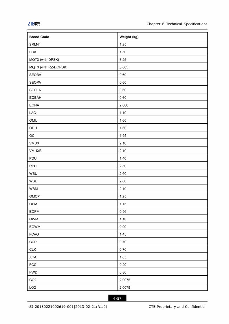
Chapter 6 Technical Specifications
Board Code Weight (kg)
SRM41 1.25
FCA 1.50
MQT3 (with DPSK) 3.25
MQT3 (with RZ-DQPSK) 3.005
SEOBA 0.60
SEOPA 0.60
SEOLA 0.60
EOBAH 0.60
EONA 2.000
LAC 1.10
OMU 1.60
ODU 1.60
OCI 1.95
VMUX 2.10
VMUXB 2.10
PDU 1.40
RPU 2.50
WBU 2.60
WSU 2.60
WBM 2.10
OMCP 1.25
OPM 1.15
EOPM 0.96
OWM 1.10
EOWM 0.90
FCAG 1.45
CCP 0.70
CLK 0.70
XCA 1.85
FCC 0.20
PWD 0.80
CO2 2.0075
LO2 2.0075
6-57
SJ-20130221092619-001|2013-02-21(R1.0) ZTE Proprietary and Confidential
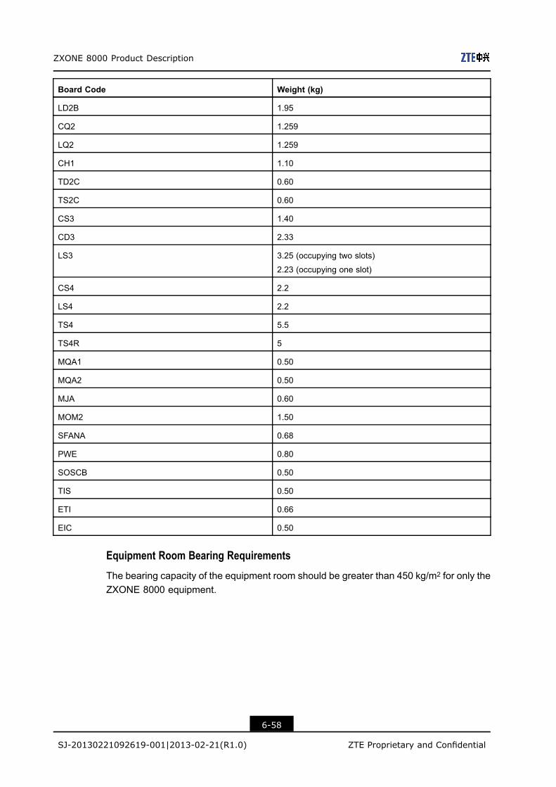
ZXONE 8000 Product Description
Board Code Weight (kg)
LD2B 1.95
CQ2 1.259
LQ2 1.259
CH1 1.10
TD2C 0.60
TS2C 0.60
CS3 1.40
CD3 2.33
LS3 3.25 (occupying two slots)
2.23 (occupying one slot)
CS4 2.2
LS4 2.2
TS4 5.5
TS4R 5
MQA1 0.50
MQA2 0.50
MJA 0.60
MOM2 1.50
SFANA 0.68
PWE 0.80
SOSCB 0.50
TIS 0.50
ETI 0.66
EIC 0.50
Equipment Room Bearing Requirements
The bearing capacity of the equipment room should be greater than 450 kg/m2 for only theZXONE 8000 equipment.
6-58
SJ-20130221092619-001|2013-02-21(R1.0) ZTE Proprietary and Confidential

Appendix AStandards andRecommendationsFor standards and recommendations with which the ZXONE 8000 system complies, referto Table A-1.
Table A-1 Standards and Recommendations with Which the ZXONE 8000 Complies
Standard/Recom-mendation
Description
ITU-T G.661 Definition and test methods for the relevant generic parameters of optical fibre
amplifiers
ITU-T G.662 Generic characteristics of optical fiber amplifier devices and subsystems
ITU-T G.663 Application related aspects of optical fibre amplifier devices and subsystems
ITU-T G.652 Characteristics of a single-mode optical fibre and cable
ITU-T G.653 Characteristics of a dispersion-shifted single-mode optical fibre and cable
ITU-T G.655 Characteristics of a non-zero dispersion-shifted single-mode optical fibre and
cable
ITU-T G.825 The control of jitter and wander within digital networks which are based on the
synchronous digital hierarchy (SDH)
ITU-T G.783 Characteristics of Synchronous Digital Hierarchy (SDH) equipment functional
blocks
ITU-T G.664 Optical safety procedures and requirements for optical transport systems
ITU-T G.665 Definitions and Test Methods for Generic Characteristics of Raman Amplifiers
and Raman Amplified Subsystems
ITU-T G.691 Optical interfaces for single channel STM-64 and other SDH systems with
optical amplifiers
ITU-T G.693 Optical interfaces for intra-office systems
ITU-T G.694.1 Spectral grids for WDM applications: Dense Wavelength Division Multiplexing
(DWDM) frequency grid
ITU-T G.694.2 Spectral Grids for WDM Applications: Coarse Wavelength Division Multiplexing
(CWDM) wavelength Grid
ITU-T G.696.1 Optical transport network physical layer interfaces
ITU-T G.697 Optical monitoring for DWDM systems
A-1
SJ-20130221092619-001|2013-02-21(R1.0) ZTE Proprietary and Confidential
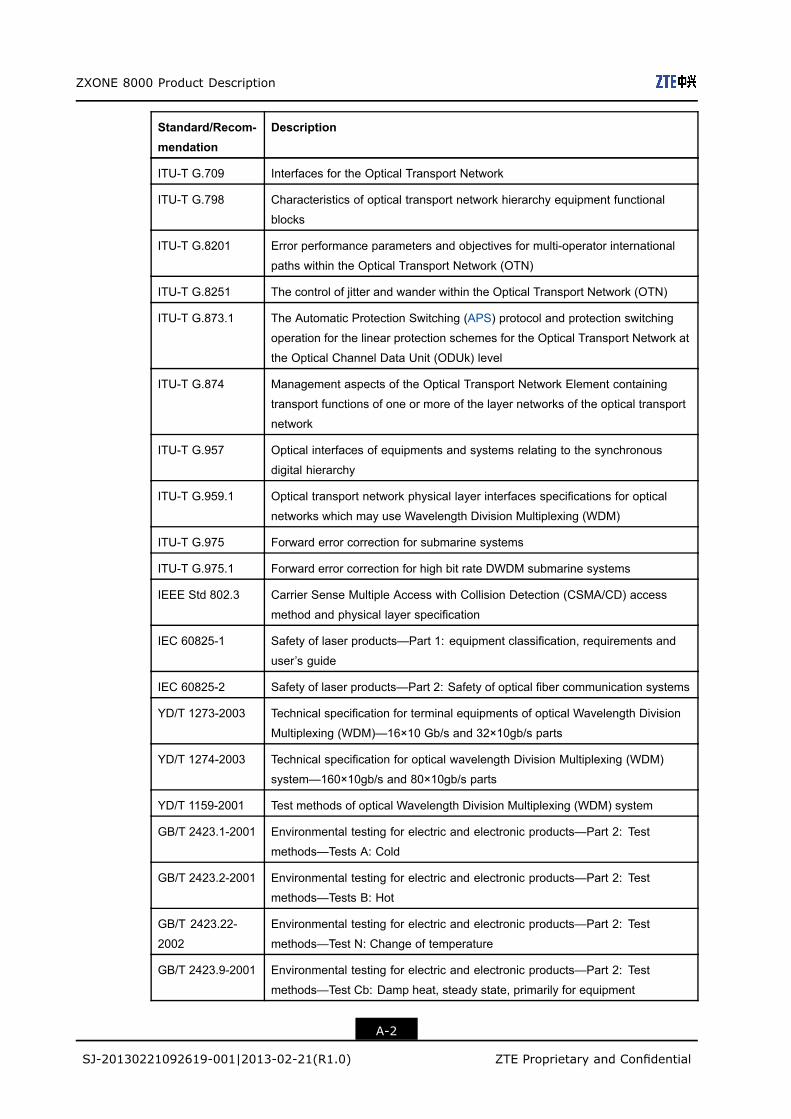
ZXONE 8000 Product Description
Standard/Recom-mendation
Description
ITU-T G.709 Interfaces for the Optical Transport Network
ITU-T G.798 Characteristics of optical transport network hierarchy equipment functional
blocks
ITU-T G.8201 Error performance parameters and objectives for multi-operator international
paths within the Optical Transport Network (OTN)
ITU-T G.8251 The control of jitter and wander within the Optical Transport Network (OTN)
ITU-T G.873.1 The Automatic Protection Switching (APS) protocol and protection switching
operation for the linear protection schemes for the Optical Transport Network at
the Optical Channel Data Unit (ODUk) level
ITU-T G.874 Management aspects of the Optical Transport Network Element containing
transport functions of one or more of the layer networks of the optical transport
network
ITU-T G.957 Optical interfaces of equipments and systems relating to the synchronous
digital hierarchy
ITU-T G.959.1 Optical transport network physical layer interfaces specifications for optical
networks which may use Wavelength Division Multiplexing (WDM)
ITU-T G.975 Forward error correction for submarine systems
ITU-T G.975.1 Forward error correction for high bit rate DWDM submarine systems
IEEE Std 802.3 Carrier Sense Multiple Access with Collision Detection (CSMA/CD) access
method and physical layer specification
IEC 60825-1 Safety of laser products—Part 1: equipment classification, requirements and
user’s guide
IEC 60825-2 Safety of laser products—Part 2: Safety of optical fiber communication systems
YD/T 1273-2003 Technical specification for terminal equipments of optical Wavelength Division
Multiplexing (WDM)—16×10 Gb/s and 32×10gb/s parts
YD/T 1274-2003 Technical specification for optical wavelength Division Multiplexing (WDM)
system—160×10gb/s and 80×10gb/s parts
YD/T 1159-2001 Test methods of optical Wavelength Division Multiplexing (WDM) system
GB/T 2423.1-2001 Environmental testing for electric and electronic products—Part 2: Test
methods—Tests A: Cold
GB/T 2423.2-2001 Environmental testing for electric and electronic products—Part 2: Test
methods—Tests B: Hot
GB/T 2423.22-
2002
Environmental testing for electric and electronic products—Part 2: Test
methods—Test N: Change of temperature
GB/T 2423.9-2001 Environmental testing for electric and electronic products—Part 2: Test
methods—Test Cb: Damp heat, steady state, primarily for equipment
A-2
SJ-20130221092619-001|2013-02-21(R1.0) ZTE Proprietary and Confidential
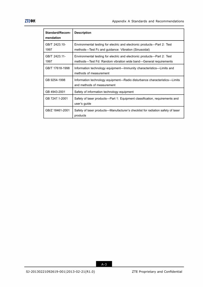
Appendix A Standards and Recommendations
Standard/Recom-mendation
Description
GB/T 2423.10-
1997
Environmental testing for electric and electronic products—Part 2: Test
methods—Test Fc and guidance: Vibration (Sinusoidal)
GB/T 2423.11-
1997
Environmental testing for electric and electronic products—Part 2: Test
methods—Test Fd: Random vibration wide band—General requirements
GB/T 17618-1998 Information technology equipment—Immunity characteristics—Limits and
methods of measurement
GB 9254-1998 Information technology equipment—Radio disturbance characteristics—Limits
and methods of measurement
GB 4943-2001 Safety of information technology equipment
GB 7247.1-2001 Safety of laser products—Part 1: Equipment classification, requirements and
user’s guide
GB/Z 18461-2001 Safety of laser products—Manufacturer’s checklist for radiation safety of laser
products
A-3
SJ-20130221092619-001|2013-02-21(R1.0) ZTE Proprietary and Confidential

ZXONE 8000 Product Description
This page intentionally left blank.
A-4
SJ-20130221092619-001|2013-02-21(R1.0) ZTE Proprietary and Confidential
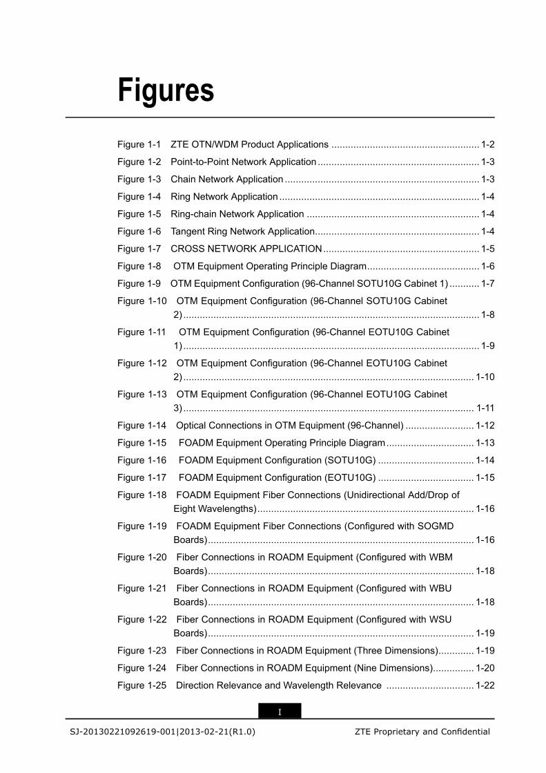
FiguresFigure 1-1 ZTE OTN/WDM Product Applications ...................................................... 1-2
Figure 1-2 Point-to-Point Network Application ........................................................... 1-3
Figure 1-3 Chain Network Application ....................................................................... 1-3
Figure 1-4 Ring Network Application ......................................................................... 1-4
Figure 1-5 Ring-chain Network Application ............................................................... 1-4
Figure 1-6 Tangent Ring Network Application............................................................ 1-4
Figure 1-7 CROSS NETWORK APPLICATION......................................................... 1-5
Figure 1-8 OTM Equipment Operating Principle Diagram......................................... 1-6
Figure 1-9 OTM Equipment Configuration (96-Channel SOTU10G Cabinet 1) ........... 1-7
Figure 1-10 OTM Equipment Configuration (96-Channel SOTU10G Cabinet2) ............................................................................................................ 1-8
Figure 1-11 OTM Equipment Configuration (96-Channel EOTU10G Cabinet1) ............................................................................................................ 1-9
Figure 1-12 OTM Equipment Configuration (96-Channel EOTU10G Cabinet2) .......................................................................................................... 1-10
Figure 1-13 OTM Equipment Configuration (96-Channel EOTU10G Cabinet3) .......................................................................................................... 1-11
Figure 1-14 Optical Connections in OTM Equipment (96-Channel) ......................... 1-12
Figure 1-15 FOADM Equipment Operating Principle Diagram................................ 1-13
Figure 1-16 FOADM Equipment Configuration (SOTU10G) ................................... 1-14
Figure 1-17 FOADM Equipment Configuration (EOTU10G) ................................... 1-15
Figure 1-18 FOADM Equipment Fiber Connections (Unidirectional Add/Drop ofEight Wavelengths)............................................................................... 1-16
Figure 1-19 FOADM Equipment Fiber Connections (Configured with SOGMDBoards)................................................................................................. 1-16
Figure 1-20 Fiber Connections in ROADM Equipment (Configured with WBMBoards)................................................................................................. 1-18
Figure 1-21 Fiber Connections in ROADM Equipment (Configured with WBUBoards)................................................................................................. 1-18
Figure 1-22 Fiber Connections in ROADM Equipment (Configured with WSUBoards)................................................................................................. 1-19
Figure 1-23 Fiber Connections in ROADM Equipment (Three Dimensions)............. 1-19
Figure 1-24 Fiber Connections in ROADM Equipment (Nine Dimensions)............... 1-20
Figure 1-25 Direction Relevance and Wavelength Relevance ................................ 1-22
I
SJ-20130221092619-001|2013-02-21(R1.0) ZTE Proprietary and Confidential
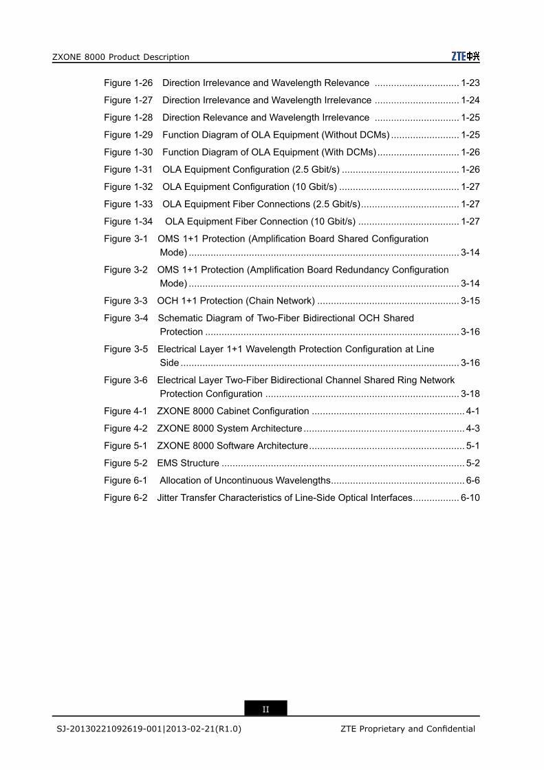
ZXONE 8000 Product Description
Figure 1-26 Direction Irrelevance and Wavelength Relevance ............................... 1-23
Figure 1-27 Direction Irrelevance and Wavelength Irrelevance ............................... 1-24
Figure 1-28 Direction Relevance and Wavelength Irrelevance ............................... 1-25
Figure 1-29 Function Diagram of OLA Equipment (Without DCMs) ......................... 1-25
Figure 1-30 Function Diagram of OLA Equipment (With DCMs) .............................. 1-26
Figure 1-31 OLA Equipment Configuration (2.5 Gbit/s) ........................................... 1-26
Figure 1-32 OLA Equipment Configuration (10 Gbit/s) ............................................ 1-27
Figure 1-33 OLA Equipment Fiber Connections (2.5 Gbit/s).................................... 1-27
Figure 1-34 OLA Equipment Fiber Connection (10 Gbit/s) ..................................... 1-27
Figure 3-1 OMS 1+1 Protection (Amplification Board Shared ConfigurationMode) ................................................................................................... 3-14
Figure 3-2 OMS 1+1 Protection (Amplification Board Redundancy ConfigurationMode) ................................................................................................... 3-14
Figure 3-3 OCH 1+1 Protection (Chain Network) .................................................... 3-15
Figure 3-4 Schematic Diagram of Two-Fiber Bidirectional OCH SharedProtection ............................................................................................. 3-16
Figure 3-5 Electrical Layer 1+1 Wavelength Protection Configuration at LineSide ...................................................................................................... 3-16
Figure 3-6 Electrical Layer Two-Fiber Bidirectional Channel Shared Ring NetworkProtection Configuration ....................................................................... 3-18
Figure 4-1 ZXONE 8000 Cabinet Configuration ........................................................ 4-1
Figure 4-2 ZXONE 8000 System Architecture ........................................................... 4-3
Figure 5-1 ZXONE 8000 Software Architecture......................................................... 5-1
Figure 5-2 EMS Structure ......................................................................................... 5-2
Figure 6-1 Allocation of Uncontinuous Wavelengths................................................. 6-6
Figure 6-2 Jitter Transfer Characteristics of Line-Side Optical Interfaces................. 6-10
II
SJ-20130221092619-001|2013-02-21(R1.0) ZTE Proprietary and Confidential
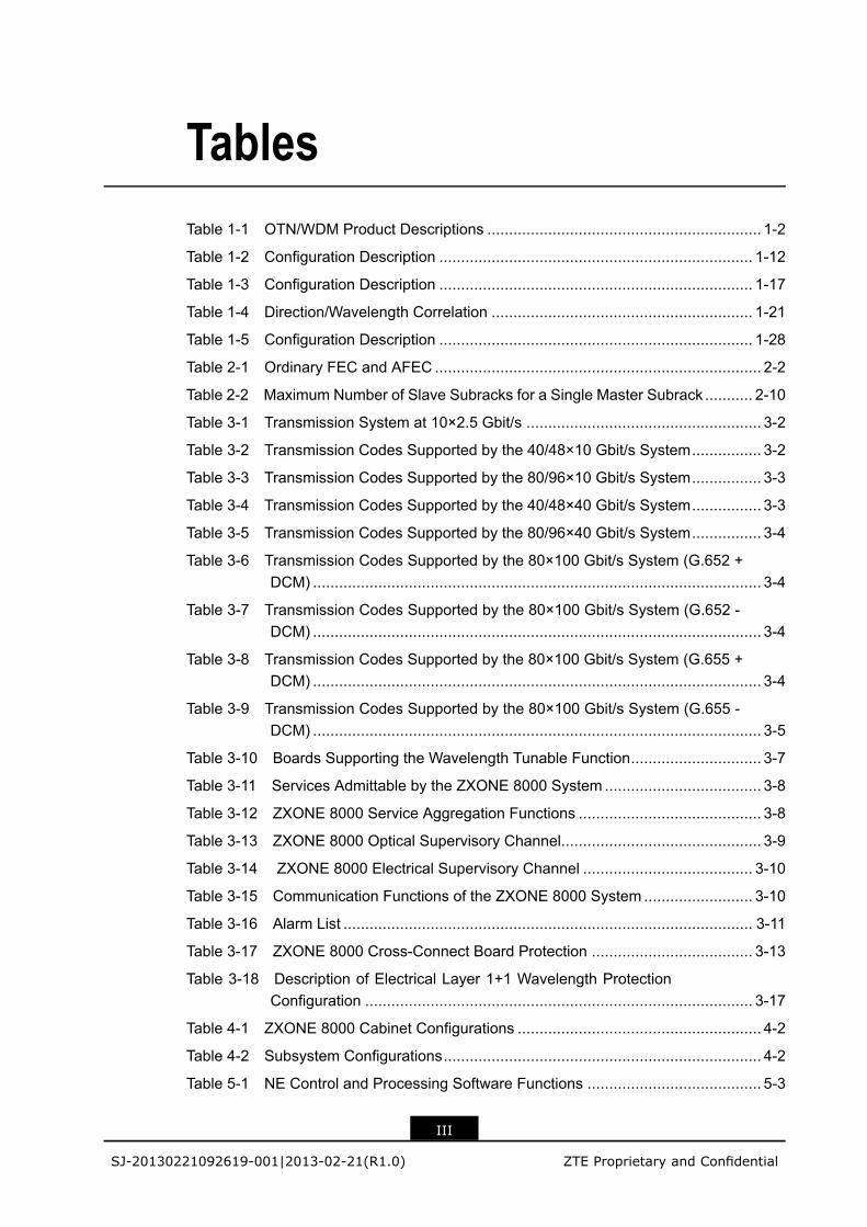
TablesTable 1-1 OTN/WDM Product Descriptions ............................................................... 1-2
Table 1-2 Configuration Description ........................................................................ 1-12
Table 1-3 Configuration Description ........................................................................ 1-17
Table 1-4 Direction/Wavelength Correlation ............................................................ 1-21
Table 1-5 Configuration Description ........................................................................ 1-28
Table 2-1 Ordinary FEC and AFEC ........................................................................... 2-2
Table 2-2 Maximum Number of Slave Subracks for a Single Master Subrack ........... 2-10
Table 3-1 Transmission System at 10×2.5 Gbit/s ...................................................... 3-2
Table 3-2 Transmission Codes Supported by the 40/48×10 Gbit/s System................ 3-2
Table 3-3 Transmission Codes Supported by the 80/96×10 Gbit/s System................ 3-3
Table 3-4 Transmission Codes Supported by the 40/48×40 Gbit/s System................ 3-3
Table 3-5 Transmission Codes Supported by the 80/96×40 Gbit/s System................ 3-4
Table 3-6 Transmission Codes Supported by the 80×100 Gbit/s System (G.652 +DCM) ....................................................................................................... 3-4
Table 3-7 Transmission Codes Supported by the 80×100 Gbit/s System (G.652 -DCM) ....................................................................................................... 3-4
Table 3-8 Transmission Codes Supported by the 80×100 Gbit/s System (G.655 +DCM) ....................................................................................................... 3-4
Table 3-9 Transmission Codes Supported by the 80×100 Gbit/s System (G.655 -DCM) ....................................................................................................... 3-5
Table 3-10 Boards Supporting the Wavelength Tunable Function.............................. 3-7
Table 3-11 Services Admittable by the ZXONE 8000 System .................................... 3-8
Table 3-12 ZXONE 8000 Service Aggregation Functions .......................................... 3-8
Table 3-13 ZXONE 8000 Optical Supervisory Channel.............................................. 3-9
Table 3-14 ZXONE 8000 Electrical Supervisory Channel ....................................... 3-10
Table 3-15 Communication Functions of the ZXONE 8000 System ......................... 3-10
Table 3-16 Alarm List .............................................................................................. 3-11
Table 3-17 ZXONE 8000 Cross-Connect Board Protection ..................................... 3-13
Table 3-18 Description of Electrical Layer 1+1 Wavelength ProtectionConfiguration ......................................................................................... 3-17
Table 4-1 ZXONE 8000 Cabinet Configurations ........................................................ 4-2
Table 4-2 Subsystem Configurations......................................................................... 4-2
Table 5-1 NE Control and Processing Software Functions ........................................ 5-3
III
SJ-20130221092619-001|2013-02-21(R1.0) ZTE Proprietary and Confidential
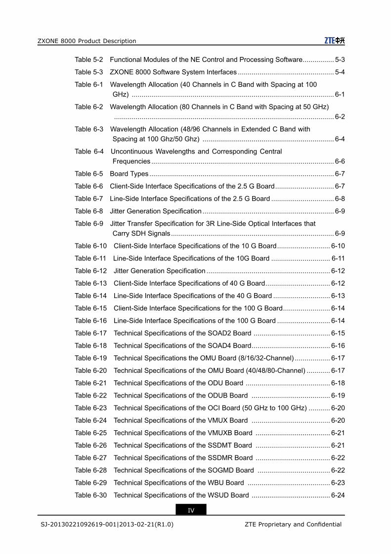
ZXONE 8000 Product Description
Table 5-2 Functional Modules of the NE Control and Processing Software................ 5-3
Table 5-3 ZXONE 8000 Software System Interfaces ................................................. 5-4
Table 6-1 Wavelength Allocation (40 Channels in C Band with Spacing at 100GHz) ....................................................................................................... 6-1
Table 6-2 Wavelength Allocation (80 Channels in C Band with Spacing at 50 GHz)................................................................................................................ 6-2
Table 6-3 Wavelength Allocation (48/96 Channels in Extended C Band withSpacing at 100 Ghz/50 Ghz) ................................................................... 6-4
Table 6-4 Uncontinuous Wavelengths and Corresponding CentralFrequencies ............................................................................................. 6-6
Table 6-5 Board Types .............................................................................................. 6-7
Table 6-6 Client-Side Interface Specifications of the 2.5 G Board.............................. 6-7
Table 6-7 Line-Side Interface Specifications of the 2.5 G Board ................................ 6-8
Table 6-8 Jitter Generation Specification ................................................................... 6-9
Table 6-9 Jitter Transfer Specification for 3R Line-Side Optical Interfaces thatCarry SDH Signals................................................................................... 6-9
Table 6-10 Client-Side Interface Specifications of the 10 G Board........................... 6-10
Table 6-11 Line-Side Interface Specifications of the 10G Board .............................. 6-11
Table 6-12 Jitter Generation Specification ............................................................... 6-12
Table 6-13 Client-Side Interface Specifications of 40 G Board................................. 6-12
Table 6-14 Line-Side Interface Specifications of the 40 G Board ............................. 6-13
Table 6-15 Client-Side Interface Specifications for the 100 G Board........................ 6-14
Table 6-16 Line-Side Interface Specifications of the 100 G Board ........................... 6-14
Table 6-17 Technical Specifications of the SOAD2 Board ....................................... 6-15
Table 6-18 Technical Specifications of the SOAD4 Board........................................ 6-16
Table 6-19 Technical Specifications the OMU Board (8/16/32-Channel) .................. 6-17
Table 6-20 Technical Specifications of the OMU Board (40/48/80-Channel) ............ 6-17
Table 6-21 Technical Specifications of the ODU Board ........................................... 6-18
Table 6-22 Technical Specifications of the ODUB Board ........................................ 6-19
Table 6-23 Technical Specifications of the OCI Board (50 GHz to 100 GHz) ........... 6-20
Table 6-24 Technical Specifications of the VMUX Board ........................................ 6-20
Table 6-25 Technical Specifications of the VMUXB Board ...................................... 6-21
Table 6-26 Technical Specifications of the SSDMT Board ...................................... 6-21
Table 6-27 Technical Specifications of the SSDMR Board ...................................... 6-22
Table 6-28 Technical Specifications of the SOGMD Board ..................................... 6-22
Table 6-29 Technical Specifications of the WBU Board .......................................... 6-23
Table 6-30 Technical Specifications of the WSUD Board ........................................ 6-24
IV
SJ-20130221092619-001|2013-02-21(R1.0) ZTE Proprietary and Confidential
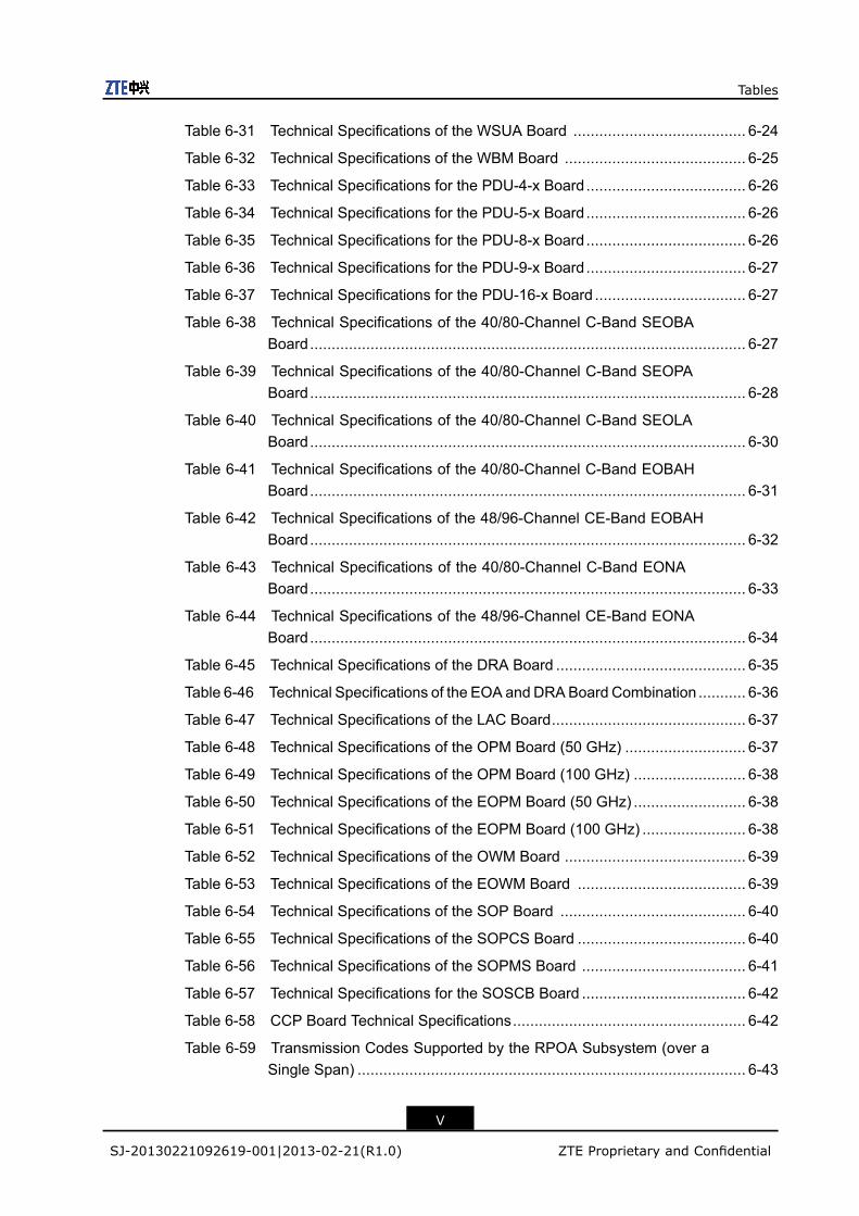
Tables
Table 6-31 Technical Specifications of the WSUA Board ........................................ 6-24
Table 6-32 Technical Specifications of the WBM Board .......................................... 6-25
Table 6-33 Technical Specifications for the PDU-4-x Board..................................... 6-26
Table 6-34 Technical Specifications for the PDU-5-x Board..................................... 6-26
Table 6-35 Technical Specifications for the PDU-8-x Board..................................... 6-26
Table 6-36 Technical Specifications for the PDU-9-x Board..................................... 6-27
Table 6-37 Technical Specifications for the PDU-16-x Board ................................... 6-27
Table 6-38 Technical Specifications of the 40/80-Channel C-Band SEOBABoard..................................................................................................... 6-27
Table 6-39 Technical Specifications of the 40/80-Channel C-Band SEOPABoard..................................................................................................... 6-28
Table 6-40 Technical Specifications of the 40/80-Channel C-Band SEOLABoard..................................................................................................... 6-30
Table 6-41 Technical Specifications of the 40/80-Channel C-Band EOBAHBoard..................................................................................................... 6-31
Table 6-42 Technical Specifications of the 48/96-Channel CE-Band EOBAHBoard..................................................................................................... 6-32
Table 6-43 Technical Specifications of the 40/80-Channel C-Band EONABoard..................................................................................................... 6-33
Table 6-44 Technical Specifications of the 48/96-Channel CE-Band EONABoard..................................................................................................... 6-34
Table 6-45 Technical Specifications of the DRA Board ............................................ 6-35
Table 6-46 Technical Specifications of the EOA and DRABoard Combination ........... 6-36
Table 6-47 Technical Specifications of the LAC Board............................................. 6-37
Table 6-48 Technical Specifications of the OPM Board (50 GHz) ............................ 6-37
Table 6-49 Technical Specifications of the OPM Board (100 GHz) .......................... 6-38
Table 6-50 Technical Specifications of the EOPM Board (50 GHz) .......................... 6-38
Table 6-51 Technical Specifications of the EOPM Board (100 GHz) ........................ 6-38
Table 6-52 Technical Specifications of the OWM Board .......................................... 6-39
Table 6-53 Technical Specifications of the EOWM Board ....................................... 6-39
Table 6-54 Technical Specifications of the SOP Board ........................................... 6-40
Table 6-55 Technical Specifications of the SOPCS Board ....................................... 6-40
Table 6-56 Technical Specifications of the SOPMS Board ...................................... 6-41
Table 6-57 Technical Specifications for the SOSCB Board ...................................... 6-42
Table 6-58 CCP Board Technical Specifications...................................................... 6-42
Table 6-59 Transmission Codes Supported by the RPOA Subsystem (over aSingle Span) .......................................................................................... 6-43
V
SJ-20130221092619-001|2013-02-21(R1.0) ZTE Proprietary and Confidential
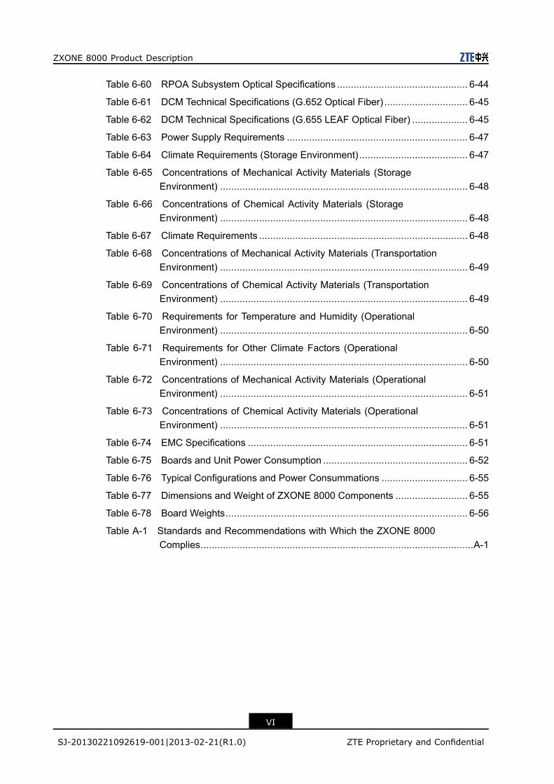
ZXONE 8000 Product Description
Table 6-60 RPOA Subsystem Optical Specifications ............................................... 6-44
Table 6-61 DCM Technical Specifications (G.652 Optical Fiber) .............................. 6-45
Table 6-62 DCM Technical Specifications (G.655 LEAF Optical Fiber) .................... 6-45
Table 6-63 Power Supply Requirements ................................................................. 6-47
Table 6-64 Climate Requirements (Storage Environment) ....................................... 6-47
Table 6-65 Concentrations of Mechanical Activity Materials (StorageEnvironment) ......................................................................................... 6-48
Table 6-66 Concentrations of Chemical Activity Materials (StorageEnvironment) ......................................................................................... 6-48
Table 6-67 Climate Requirements ........................................................................... 6-48
Table 6-68 Concentrations of Mechanical Activity Materials (TransportationEnvironment) ......................................................................................... 6-49
Table 6-69 Concentrations of Chemical Activity Materials (TransportationEnvironment) ......................................................................................... 6-49
Table 6-70 Requirements for Temperature and Humidity (OperationalEnvironment) ......................................................................................... 6-50
Table 6-71 Requirements for Other Climate Factors (OperationalEnvironment) ......................................................................................... 6-50
Table 6-72 Concentrations of Mechanical Activity Materials (OperationalEnvironment) ......................................................................................... 6-51
Table 6-73 Concentrations of Chemical Activity Materials (OperationalEnvironment) ......................................................................................... 6-51
Table 6-74 EMC Specifications ............................................................................... 6-51
Table 6-75 Boards and Unit Power Consumption .................................................... 6-52
Table 6-76 Typical Configurations and Power Consummations ............................... 6-55
Table 6-77 Dimensions and Weight of ZXONE 8000 Components .......................... 6-55
Table 6-78 Board Weights....................................................................................... 6-56
Table A-1 Standards and Recommendations with Which the ZXONE 8000Complies..................................................................................................A-1
VI
SJ-20130221092619-001|2013-02-21(R1.0) ZTE Proprietary and Confidential

GlossaryAFEC- Advanced Forward Error Correction
APC- Automatic Power Control
APR- Automatic Power Reduction
APSD- Automatic Power Shutdown
AWG- Array Waveguide Grating
DFB-LD- Distributed Feedback Laser Diode
DRA- Distributed RAMAN fiber Amplifier
DWDM- Dense Wavelength Division Multiplexing
EA- Electrical Absorption
EDF- Erbium Doped Fiber
EDFA- Erbium Doped Fiber Amplifier
EMC- Electro Magnetic Compatibility
EMI- Electromagnetic Interference
FEB- Floor Equipotential earthing terminal Board
FEC- Forward Error Correction
MET- Main Earthing Terminal
NE- Network Element
VII
SJ-20130221092619-001|2013-02-21(R1.0) ZTE Proprietary and Confidential
ZXONE 8000 Product Description
OSNR- Optical Signal-to-Noise Ratio
OTM- Optical Terminal Multiplexer
OTN- Optical Transport Network
PDL- Polarization Dependent Loss
PMD- Polarization Mode Dispersion
QoS- Quality of Service
ROADM- Reconfigurable Optical Add/Drop Multiplexer
RPOA- Remotely Pumped Optical Amplifier
SDH- Synchronous Digital Hierarchy
SFP- Small Form-factor Pluggable
SNR- Signal to Noise Ratio
TFF- Thin Film Filter
VLAN- Virtual Local Area Network
VOA- Variable Optical Attenuator
WDM- Wavelength Division Multiplexing
XFP- 10 Gigabit small Form-factor Pluggable transceiver
VIII
SJ-20130221092619-001|2013-02-21(R1.0) ZTE Proprietary and Confidential