- 2 - iec dis 1131-3 - unina.itwpage.unina.it/detommas/tsa/standardiec_61131_3.pdf- 2 - iec dis...
TRANSCRIPT

- 2 - IEC DIS 1131-3
FOREWORD
This document is Part 3 of IEC Standard 1131 for programmable controllers. The current status of the various Parts of IEC 1131 is as follows:
Part 1 - General Information (IS) Part 2 - Equipment and Test Requirements (IS) Part 3 - Programming Languages (This Part - DIS) Part 4 - User Guidelines (CD) Part 5 - Messaging Service (CD)
This document was prepared by Task Force 3 (Programming Languages) of Working Group 7 (Programmable Controllers) of IEC Subcommittee 65B (formerly SC65A/WG6).
Annexes A, B, C, D, and E of this document are normative. It is anticipated that, as industrial practice matures, a normative annex H will be developed.
A Type 2 Technical Report (TR) will provide "pre-standardization" guidance for the implementation and application of the programming languages defined in this document , including such issues as operating system/program interaction and requirements for programming support environments.

IEC DIS 1131-3 - 3 -
CONTENTS Clause/subclause Page
1. General ............................................................................................................................................... 9 1.1 Scope ................................................................................................................................................ 9 1.2 Normative references ....................................................................................................................... 9 1.3 Definitions ....................................................................................................................................... 10 1.4 Overview and general requirements .............................................................................................. 14 1.4.1 Software model ............................................................................................................................ 15 1.4.2 Communication model ................................................................................................................. 15 1.4.3 Programming model .................................................................................................................... 19 1.5 Compliance ..................................................................................................................................... 21 1.5.1 Programmable controller systems ............................................................................................... 21 1.5.2 Programs ..................................................................................................................................... 23
2. Common elements ........................................................................................................................... 24 2.1 Use of printed characters ............................................................................................................... 24 2.1.1 Character set ............................................................................................................................... 24 2.1.2 Identifiers ..................................................................................................................................... 25 2.1.3 Keywords ..................................................................................................................................... 26 2.1.4 Use of spaces ............................................................................................................................... 26 2.1.5 Comments ................................................................................................................................... 26 2.2 External representation of data ...................................................................................................... 27 2.2.1 Numeric literals ............................................................................................................................ 27 2.2.2 Character string literals ................................................................................................................ 28 2.2.3 Time literals ................................................................................................................................. 29 2.2.3.1 Duration .................................................................................................................................... 29 2.2.3.2 Time of day and date ................................................................................................................ 30 2.3 Data types ....................................................................................................................................... 30 2.3.1 Elementary data types ................................................................................................................. 30 2.3.2 Generic data types ...................................................................................................................... 32 2.3.3 Derived data types ....................................................................................................................... 33 2.3.3.1 Declaration ............................................................................................................................... 33 2.3.3.2 Initialization ............................................................................................................................... 33 2.3.3.3 Usage ........................................................................................................................................ 36 2.4 Variables ......................................................................................................................................... 37 2.4.1 Representation ............................................................................................................................ 37 2.4.1.1 Single-element variables .......................................................................................................... 37 2.4.1.2 Multi-element variables ............................................................................................................. 38 2.4.2 Initialization .................................................................................................................................. 39 2.4.3 Declaration................................................................................................................................... 39 2.4.3.1 Type assignment ...................................................................................................................... 40 2.4.3.2 Initial value assignment ............................................................................................................ 42 2.5 Program organization units............................................................................................................. 44 2.5.1 Functions ..................................................................................................................................... 44 2.5.1.1 Representation ......................................................................................................................... 45 2.5.1.2 Execution control ...................................................................................................................... 46 2.5.1.3 Declaration ............................................................................................................................... 47 2.5.1.4 Typing, overloading, and type conversion ................................................................................ 48 2.5.1.5 Standard functions .................................................................................................................... 50

- 4 - IEC DIS 1131-3
CONTENTS (continued) Clause/subclause Page
2.5.1.5.1 Type conversion functions ..................................................................................................... 50 2.5.1.5.2 Numerical functions ................................................................................................................ 52 2.5.1.5.3 Bit string functions .................................................................................................................. 54 2.5.1.5.4 Selection and comparison functions ...................................................................................... 54 2.5.1.5.5 Character string functions ...................................................................................................... 58 2.5.1.5.6 Functions of time data types .................................................................................................. 59 2.5.1.5.7 Functions of enumerated data types ...................................................................................... 59 2.5.2 Function blocks ............................................................................................................................ 61 2.5.2.1 Representation .......................................................................................................................... 61 2.5.2.2 Declaration ................................................................................................................................ 63 2.5.2.3 Standard function blocks ........................................................................................................... 70 2.5.2.3.1 Bistable elements ................................................................................................................... 70 2.5.2.3.2 Edge detection ....................................................................................................................... 72 2.5.2.3.3 Counters ................................................................................................................................. 73 2.5.2.3.4 Timers .................................................................................................................................... 74 2.5.2.3.5 Communication function blocks ............................................................................................. 76 2.5.3 Programs ...................................................................................................................................... 76 2.6 Sequential Function Chart (SFC) elements .................................................................................... 77 2.6.1 General ......................................................................................................................................... 77 2.6.2 Steps ............................................................................................................................................ 77 2.6.3 Transitions .................................................................................................................................... 79 2.6.4 Actions .......................................................................................................................................... 83 2.6.4.1 Declaration ................................................................................................................................ 83 2.6.4.2 Association with steps ............................................................................................................... 86 2.6.4.3 Action blocks ............................................................................................................................. 87 2.6.4.4 Action qualifiers ......................................................................................................................... 88 2.6.4.5 Action control ............................................................................................................................. 88 2.6.5 Rules of evolution ......................................................................................................................... 93 2.6.6 Compatibility of SFC elements ................................................................................................... 104 2.6.7 Compliance requirements .......................................................................................................... 104 2.7 Configuration elements ................................................................................................................. 105 2.7.1 Configurations, resources, and access paths ............................................................................ 107 2.7.2 Tasks .......................................................................................................................................... 110
3. Textual languages ........................................................................................................................... 118 3.1 Common elements ........................................................................................................................ 118 3.2 Language IL (Instruction List) ........................................................................................................ 119 3.2.1 Instructions ................................................................................................................................. 119 3.2.2 Operators, modifiers and operands ........................................................................................... 119 3.2.3 Functions and function blocks .................................................................................................... 121 3.3 Language ST (Structured Text) ..................................................................................................... 122 3.3.1 Expressions ................................................................................................................................ 122 3.3.2 Statements ................................................................................................................................. 124 3.3.2.1 Assignment statements ........................................................................................................... 125 3.3.2.2 Function and function block control statements ...................................................................... 125 3.3.2.3 Selection statements ............................................................................................................... 126 3.3.2.4 Iteration statements ................................................................................................................. 126
4. Graphic languages .......................................................................................................................... 128 4.1 Common elements ........................................................................................................................ 128 4.1.1 Representation of lines and blocks ............................................................................................. 128 4.1.2 Direction of flow in networks ...................................................................................................... 128

IEC DIS 1131-3 - 5 -
CONTENTS (continued) Clause/subclause Page
4.1.3 Evaluation of networks .............................................................................................................. 130 4.1.4 Execution control elements ....................................................................................................... 132 4.2 Language LD (Ladder Diagram) ................................................................................................... 134 4.2.1 Power rails ................................................................................................................................. 134 4.2.2 Link elements and states ........................................................................................................... 134 4.2.3 Contacts ..................................................................................................................................... 135 4.2.4 Coils ........................................................................................................................................... 135 4.2.5 Functions and function blocks ................................................................................................... 135 4.2.6 Order of network evaluation ...................................................................................................... 135 4.3 Language FBD (Function Block Diagram) ................................................................................... 138 4.3.1 General ...................................................................................................................................... 138 4.3.2 Combination of elements ........................................................................................................... 138 4.3.3 Order of network evaluation ...................................................................................................... 138
ANNEX A - Specification method for textual languages (normative) .................................................. 139 A.1 Syntax .......................................................................................................................................... 139 A.1.1 Terminal symbols .................................................................................................................... 139 A.1.2 Non-terminal symbols ............................................................................................................. 139 A.1.3 Production rules ....................................................................................................................... 140 A.2 Semantics ..................................................................................................................................... 140
ANNEX B - Formal specifications of language elements (normative) ................................................. 141 B.0 Programming model ..................................................................................................................... 141 B.1 Common elements ....................................................................................................................... 142 B.1.1 Letters, digits and identifiers ...................................................................................................... 142 B.1.2 Constants .................................................................................................................................. 142 B.1.2.1 Numeric literals ..................................................................................................................... 142 B.1.2.2 Character strings .................................................................................................................... 143 B.1.2.3 Time literals ............................................................................................................................. 143 B.1.2.3.1 Duration ............................................................................................................................... 143 B.1.2.3.2 Time of day and date .......................................................................................................... 144 B.1.3 Data types ................................................................................................................................ 144 B.1.3.1 Elementary data types ........................................................................................................... 144 B.1.3.2 Generic data types ................................................................................................................. 145 B.1.3.3 Derived data types ................................................................................................................. 145 B.1.4 Variables ................................................................................................................................... 146 B.1.4.1 Directly represented variables ............................................................................................... 146 B.1.4.2 Multi-element variables .......................................................................................................... 147 B.1.4.3 Declaration and initialization .................................................................................................. 147 B.1.5 Program organization units ....................................................................................................... 149 B.1.5.1 Functions ................................................................................................................................ 149 B.1.5.2 Function blocks ...................................................................................................................... 150 B.1.5.3 Programs ................................................................................................................................ 150 B.1.6 Sequential function chart elements ........................................................................................... 151 B.1.7 Configuration elements ............................................................................................................. 152 B.2 Language IL (Instruction List) ...................................................................................................... 153 B.2.1 Instructions and operands ......................................................................................................... 153 B.2.2 Operators .................................................................................................................................. 153
- 6 - IEC DIS 1131-3
CONTENTS (continued) Clause/subclause Page
B.3 Language ST (Structured Text) .................................................................................................... 154 B.3.1 Expressions ............................................................................................................................... 154 B.3.2 Statements ................................................................................................................................. 154 B.3.2.1 Assignment statements .......................................................................................................... 154 B.3.2.2 Subprogram control statements ............................................................................................. 155 B.3.2.3 Selection statements .............................................................................................................. 155 B.3.2.4 Iteration statements ................................................................................................................ 155
ANNEX C - Delimiters and Keywords (normative) ............................................................................... 156
ANNEX D - Implementation-dependent parameters (normative) ........................................................ 160
ANNEX E - Error Conditions (normative) ............................................................................................. 162
ANNEX F - Examples (informative) ..................................................................................................... 163 F.1 Function WEIGH ........................................................................................................................... 163 F.2 Function block CMD_MONITOR .................................................................................................. 164 F.3 Function block FWD_REV_MON .................................................................................................. 167 F.4 Function block STACK_INT .......................................................................................................... 173 F.5 Function block MIX_2_BRIX ......................................................................................................... 178 F.6 Analog signal processing .............................................................................................................. 182 F.6.1 Function block LAG1 .................................................................................................................. 182 F.6.2 Function block DELAY ............................................................................................................... 183 F.6.3 Function block AVERAGE ......................................................................................................... 184 F.6.4 Function block INTEGRAL ......................................................................................................... 185 F.6.5 Function block DERIVATIVE ..................................................................................................... 186 F.6.6 Function block HYSTERESIS .................................................................................................... 186 F.6.7 Function block LIMITS_ALARM ................................................................................................. 187 F.6.8 Structure ANALOG_LIMITS ....................................................................................................... 188 F.6.9 Function block ANALOG_MONITOR ......................................................................................... 189 F.6.10 Function block PID .................................................................................................................... 190 F.6.11 Function block DIFFEQ ............................................................................................................. 191 F.6.12 Function block RAMP .............................................................................................................. 192 F.6.13 Function block TRANSFER ..................................................................................................... 193 F.7 Program GRAVEL ......................................................................................................................... 194 F.8 Program AGV ................................................................................................................................ 203
ANNEX G - Index (informative) ............................................................................................................ 207
ANNEX H - Software compliance testing (informative) ........................................................................ 220
1 - Character set features ...................................................................................................................... 25 2 - Identifier features .............................................................................................................................. 25 3 - Comment feature .............................................................................................................................. 26 4 - Numeric literals ................................................................................................................................. 27 5 - Character string literal feature ........................................................................................................... 28 6 - Two-character combinations in character strings ............................................................................. 28 7 - Duration literal features ..................................................................................................................... 29 8 - Date and time of day literals ............................................................................................................. 30 9 - Examples of date and time of day literals ......................................................................................... 30 10 - Elementary data types .................................................................................................................... 31
IEC DIS 1131-3 - 7 -
CONTENTS (continued) Clause/subclause Page
11 - Hierarchy of generic data types ..................................................................................................... 32 12 - Data type declaration features ....................................................................................................... 34 13 - Default initial values ....................................................................................................................... 34 14 - Data type initial value declaration features .................................................................................... 35 15 - Location and size prefix features for directly represented variables .............................................. 38 16 - Variable declaration keywords ....................................................................................................... 40 17 - Variable type assignment features ................................................................................................. 40 18 - Variable initial value assignment features ...................................................................................... 42 19 - Graphical negation of Boolean signals ........................................................................................... 45 20 - Use of EN input and ENO output ................................................................................................... 47 21 - Typed and overloaded functions .................................................................................................... 49 22 - Type conversion function features ................................................................................................. 51 23 - Standard functions of one numeric variable ................................................................................... 52 24 - Standard arithmetic functions ......................................................................................................... 53 25 - Standard bit shift functions ............................................................................................................. 54 26 - Standard bitwise Boolean functions ............................................................................................... 55 27 - Standard selection functions .......................................................................................................... 56 28 - Standard comparison functions ...................................................................................................... 57 29 - Standard character string functions ............................................................................................... 58 30 - Functions of time data types .......................................................................................................... 60 31 - Functions of enumerated data types .............................................................................................. 60 32 - Examples of function block I/O parameter usage .......................................................................... 62 33 - Function block declaration features ............................................................................................... 65 34 - Standard bistable function blocks .................................................................................................. 71 35 - Standard edge detection function blocks ....................................................................................... 72 36 - Standard counter function blocks ................................................................................................... 73 37 - Standard timer function blocks ....................................................................................................... 74 38 - Standard timer function blocks - timing diagrams .......................................................................... 74 39 - Program declaration features ......................................................................................................... 76 40 - Step features .................................................................................................................................. 78 41 - Transitions and transition conditions .............................................................................................. 80 42 - Declaration of actions ..................................................................................................................... 84 43 - Step/action association .................................................................................................................. 86 44 - Action block features ...................................................................................................................... 87 45 - Action qualifiers .............................................................................................................................. 88 46 - Sequence evolution ........................................................................................................................ 94 47 - Compatible SFC features ............................................................................................................. 104 48 - SFC minimal compliance requirements ....................................................................................... 104 49 - Configuration and resource declaration features ......................................................................... 108 50 - Task features ................................................................................................................................ 111 51 - Examples of instruction fields ....................................................................................................... 119 52 - Instruction List (IL) operators ....................................................................................................... 120 53 - Function block invocation features for IL language ...................................................................... 121 54 - Standard function block input operators for IL language ............................................................. 121 56 - ST language statements .............................................................................................................. 124 57 - Representation of lines and blocks .............................................................................................. 129 58 - Graphic execution control elements ............................................................................................. 133 59 - Power rails .................................................................................................................................... 134

- 8 - IEC DIS 1131-3
CONTENTS (continued) Clause/subclause Page
60 - Link elements ................................................................................................................................ 135 61 - Contacts ........................................................................................................................................ 136 62 - Coils .............................................................................................................................................. 137

IEC DIS 1131-3 - 9 -
LIST OF TABLES
Table Page
LIST OF FIGURES
Figure Page
1 - Software model................................................................................................................................. 16 2 - Communication model ...................................................................................................................... 17 3 - Combination of programmable controller language elements ......................................................... 20 4 - Examples of function usage ............................................................................................................. 44 5 - Use of formal parameter names ....................................................................................................... 46 6 - Examples of function declarations ................................................................................................... 48 7 - Examples of explicit type conversion with overloaded functions ..................................................... 49 8 - Examples of explicit type conversion with typed functions .............................................................. 50 9 - Function block instantiation example ............................................................................................... 62 10 - Examples of function block declarations ........................................................................................ 64 11 - Graphical use of function block names as variables ...................................................................... 66 12 - Examples of use of input/output variables ..................................................................................... 69 13 - Semaphore usage example ........................................................................................................... 70 14 - ACTION_CONTROL function block - External interface................................................................ 89 15 - ACTION_CONTROL function block body ...................................................................................... 90 16 - Action control example ................................................................................................................... 91 17 - SFC evolution rules ...................................................................................................................... 100 18 - SFC errors .................................................................................................................................... 102 19 - Configuration example ................................................................................................................. 105 20 - Examples of CONFIGURATION and RESOURCE declaration features ..................................... 109 21 - Synchronization of function blocks ............................................................................................... 115 22 - EXIT statement example .............................................................................................................. 126 23 - Feedback path example ............................................................................................................... 131 24 - Boolean OR Examples ................................................................................................................. 138

IEC DIS 1131-3 - 10 -
LIST OF TABLES
Table Page
1. General
1.1 Scope
This part of IEC 1131 applies to the printed and displayed representation, using characters of the ISO/IEC 646 character set, of the programming languages to be used for Programmable Controllers as defined in Part 1 of IEC 1131. Graphic and semigraphic representation of the language elements which are defined in this part is allowed, but is not defined in this part.
The functions of program entry, testing, monitoring, operating system, etc., are specified in Part 1 of IEC 1131.
1.2 Normative references
The following normative documents contain provisions which, through reference in this text, constitute provisions of this part of IEC 1131. At the time of publication, the editions indicated were valid. All normative documents are subject to revision, and parties to agreements based on this part of IEC 1131 are encouraged to investigate the possibility of applying the most recent editions of the normative documents indicated below. Members of IEC and ISO maintain registers of currently valid International Standards.
IEC 50: International Electrotechnical Vocabulary (IEV)
IEC 559: 1989, Binary floating-point arithmetic for microprocessors systems
IEC 617-12: 1991, Graphical symbols for diagrams, Part 12: Binary logic elements
IEC 617-13: 1978, Graphical symbols for diagrams, Part 13: Analogue elements
IEC 848: 1988, Preparation of function charts for control systems
ISO/AFNOR: 1989, Dictionary of computer science, ISBN 2-12-4869111-6
ISO/IEC 646: 1991, Information technology - ISO 7-bit coded character set for information processing interchange
ISO 8601:1988, Data elements and Interchange formats - Information interchange - Representations of dates and times
ISO 7185: 1990, Information technology - Programming languages - Pascal
ISO 7498: 1984, Information processing systems - Open systems interconnection - Basic reference model
IEC DIS 1131-3 - 11 -
LIST OF TABLES (continued)
Table Page
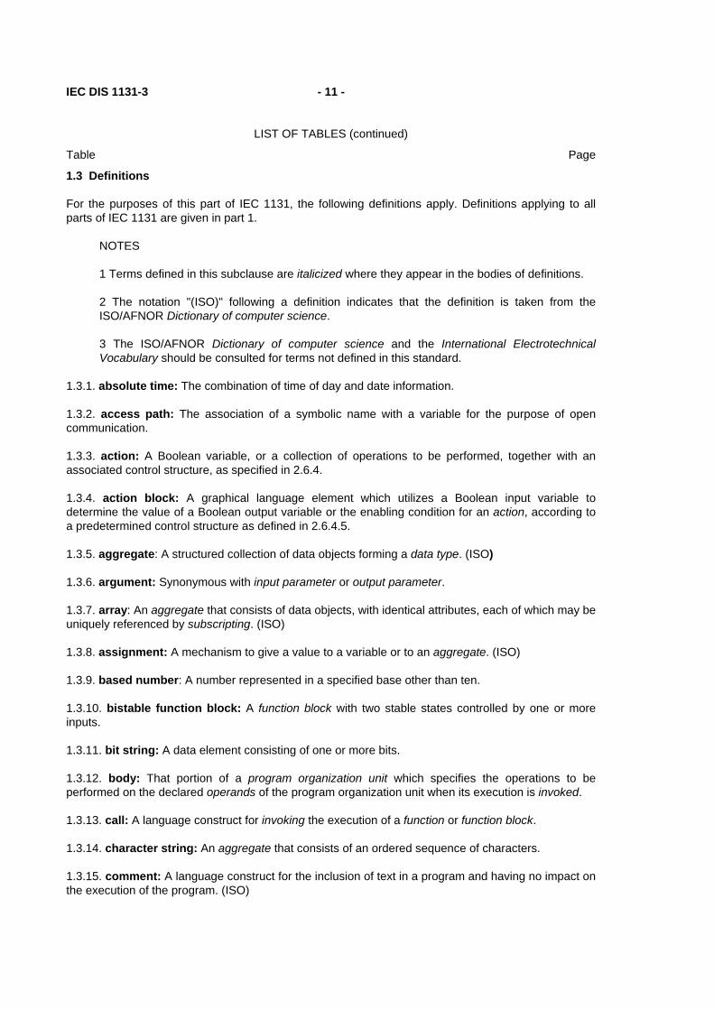
1.3 Definitions
For the purposes of this part of IEC 1131, the following definitions apply. Definitions applying to all parts of IEC 1131 are given in part 1.
NOTES
1 Terms defined in this subclause are italicized where they appear in the bodies of definitions.
2 The notation "(ISO)" following a definition indicates that the definition is taken from the ISO/AFNOR Dictionary of computer science.
3 The ISO/AFNOR Dictionary of computer science and the International Electrotechnical Vocabulary should be consulted for terms not defined in this standard.
1.3.1. absolute time: The combination of time of day and date information.
1.3.2. access path: The association of a symbolic name with a variable for the purpose of open communication.
1.3.3. action: A Boolean variable, or a collection of operations to be performed, together with an associated control structure, as specified in 2.6.4.
1.3.4. action block: A graphical language element which utilizes a Boolean input variable to determine the value of a Boolean output variable or the enabling condition for an action, according to a predetermined control structure as defined in 2.6.4.5.
1.3.5. aggregate: A structured collection of data objects forming a data type. (ISO)
1.3.6. argument: Synonymous with input parameter or output parameter.
1.3.7. array: An aggregate that consists of data objects, with identical attributes, each of which may be uniquely referenced by subscripting. (ISO)
1.3.8. assignment: A mechanism to give a value to a variable or to an aggregate. (ISO)
1.3.9. based number: A number represented in a specified base other than ten.
1.3.10. bistable function block: A function block with two stable states controlled by one or more inputs.
1.3.11. bit string: A data element consisting of one or more bits.
1.3.12. body: That portion of a program organization unit which specifies the operations to be performed on the declared operands of the program organization unit when its execution is invoked.
1.3.13. call: A language construct for invoking the execution of a function or function block.
1.3.14. character string: An aggregate that consists of an ordered sequence of characters.
1.3.15. comment: A language construct for the inclusion of text in a program and having no impact on the execution of the program. (ISO)

- 12 - IEC DIS 1131-3
LIST OF TABLES (continued)
Table Page
1.3.16. compile: To translate a program organization unit or data type specification into its machine language equivalent or an intermediate form.
1.3.17. configuration: A language element corresponding to a programmable controller system as defined in IEC 1131-1.
1.3.18. counter function block: A function block which accumulates a value for the number of changes sensed at one or more specified inputs.
1.3.19. data type: A set of values together with a set of permitted operations. (ISO)
1.3.20. date and time: The date within the year and the time of day, represented according to ISO 8601.
1.3.21. declaration: The mechanism for establishing the definition of a language element. A declaration normally involves attaching an identifier to the language element, and allocating attributes such as data types and algorithms to it.
1.3.22. delimiter: A character or combination of characters used to separate program language elements.
1.3.23. direct representation: A means of representing a variable in a programmable controller program from which a manufacturer-specified correspondence to a physical or logical location may be determined directly.
1.3.24. double word: A data element containing 32 bits.
1.3.25. evaluation: The process of establishing a value for an expression or a function, or for the outputs of a network or function block, during program execution.
1.3.26. execution control element: A language element which controls the flow of program execution.
1.3.27. falling edge: The change from 1 to 0 of a Boolean variable.
1.3.28. function: A program organization unit which, when executed, yields exactly one data element (which may be multi-valued, e.g., an array or structure), and whose invocation can be used in textual languages as an operand in an expression.
1.3.29. function block instance (function block): An instance of a function block type.
1.3.30. function block type: A programmable controller programming language element consisting of: (i) the definition of a data structure partitioned into input, output, and internal variables; and (ii) a set of operations to be performed upon the elements of the data structure when an instance of the function block type is invoked.
1.3.31. function block diagram: One or more networks of graphically represented functions, function blocks, data elements, labels, and connective elements.
1.3.32. generic data type: A data type which represents more than one type of data, as specified in 2.3.2.
1.3.33. global scope: Scope of a declaration applying to all program organization units within a resource or configuration.
IEC DIS 1131-3 - 13 -
LIST OF TABLES (continued)
Table Page
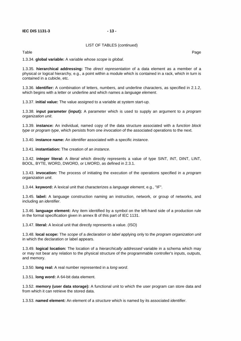
1.3.34. global variable: A variable whose scope is global.
1.3.35. hierarchical addressing: The direct representation of a data element as a member of a physical or logical hierarchy, e.g., a point within a module which is contained in a rack, which in turn is contained in a cubicle, etc.
1.3.36. identifier: A combination of letters, numbers, and underline characters, as specified in 2.1.2, which begins with a letter or underline and which names a language element.
1.3.37. initial value: The value assigned to a variable at system start-up.
1.3.38. input parameter (input): A parameter which is used to supply an argument to a program organization unit.
1.3.39. instance: An individual, named copy of the data structure associated with a function block type or program type, which persists from one invocation of the associated operations to the next.
1.3.40. instance name: An identifier associated with a specific instance.
1.3.41. instantiation: The creation of an instance.
1.3.42. integer literal: A literal which directly represents a value of type SINT, INT, DINT, LINT, BOOL, BYTE, WORD, DWORD, or LWORD, as defined in 2.3.1.
1.3.43. invocation: The process of initiating the execution of the operations specified in a program organization unit.
1.3.44. keyword: A lexical unit that characterizes a language element, e.g., "IF".
1.3.45. label: A language construction naming an instruction, network, or group of networks, and including an identifier.
1.3.46. language element: Any item identified by a symbol on the left-hand side of a production rule in the formal specification given in annex B of this part of IEC 1131.
1.3.47. literal: A lexical unit that directly represents a value. (ISO)
1.3.48. local scope: The scope of a declaration or label applying only to the program organization unit in which the declaration or label appears.
1.3.49. logical location: The location of a hierarchically addressed variable in a schema which may or may not bear any relation to the physical structure of the programmable controller's inputs, outputs, and memory.
1.3.50. long real: A real number represented in a long word.
1.3.51. long word: A 64-bit data element.
1.3.52. memory (user data storage): A functional unit to which the user program can store data and from which it can retrieve the stored data.
1.3.53. named element: An element of a structure which is named by its associated identifier.
- 14 - IEC DIS 1131-3
LIST OF TABLES (continued)
Table Page
1.3.54. off-delay (on-delay) timer function block: A function block which delays the falling (rising) edge of a Boolean input by a specified duration.
1.3.55. operand: A language element on which an operation is performed.
1.3.56. operator: A symbol that represents the action to be performed in an operation.
1.3.57. output parameter (output): A parameter which is used to return the result(s) of the evaluation of a program organization unit.
1.3.58. overloaded: With respect to an operation or function, capable of operating on data of different types, as specified in 2.5.1.4.
1.3.59. power flow: The symbolic flow of electrical power in a ladder diagram, used to denote the progression of a logic solving algorithm.
1.3.60. program (verb): To design, write, and test user programs.
1.3.61. program organization unit: A function, function block, or program. NOTE - This term may refer to either a type or an instance.
1.3.62. real literal: A literal representing data of type REAL or LREAL.
1.3.63. resource: A language element corresponding to a "signal processing function" and its "man-machine interface" and "sensor and actuator interface functions", if any, as defined in IEC 1131-1.
1.3.64. retentive data: Data stored in such a way that its value remains unchanged after a power down / power up sequence.
1.3.65. return: A language construction within a program organization unit designating an end to the execution sequences in the unit.
1.3.66. rising edge: The change from 0 to 1 of a Boolean variable.
1.3.67. scope: That portion of a language element within which a declaration or label applies.
1.3.68. semantics: The relationships between the symbolic elements of a programming language and their meanings, interpretation and use.
1.3.69. semigraphic representation: Representation of graphic information by the use of a limited set of characters.
1.3.70. single data element: A data element consisting of a single value.
1.3.71. step: A situation in which the behavior of a program organization unit with respect to its inputs and outputs follows a set of rules defined by the associated actions of the step.
1.3.72. structured data type: An aggregate data type which has been declared using a STRUCT or FUNCTION_BLOCK declaration.
1.3.73. subscripting: A mechanism for referencing an array element by means of an array reference and one or more expressions that, when evaluated, denote the position of the element.
1.3.74. symbolic representation: The use of identifiers to name variables.

IEC DIS 1131-3 - 15 -
LIST OF TABLES (continued)
Table Page
1.3.75. task: An execution control element providing for periodic or triggered execution of a group of associated program organization units.
1.3.76. time literal: A literal representing data of type TIME, DATE, TIME_OF_DAY, or DATE_AND_TIME.
1.3.77. transition: The condition whereby control passes from one or more predecessor steps to one or more successor steps along a directed link.
1.3.78. unsigned integer: An integer literal not containing a leading plus (+) or minus (-) sign.
1.3.79. wired OR: A construction for achieving the Boolean OR function in the LD language by connecting together the right ends of horizontal connectives with vertical connectives.
1.3.1. 1.3.80. single-element variable: A variable which represents a single data element.
1.4 Overview and general requirements
This part of IEC 1131 specifies the syntax and semantics of a unified suite of programming languages for programmable controllers (PCs). These consist of two textual languages, IL (Instruction List) and ST (Structured Text), and two graphical languages, LD (Ladder Diagram) and FBD (Function Block Diagram).
Sequential Function Chart (SFC) elements are defined for structuring the internal organization of programmable controller programs and function blocks. Also, configuration elements are defined which support the installation of programmable controller programs into programmable controller systems.
In addition, features are defined which facilitate communication among programmable controllers and other components of automated systems.
The programming language elements defined in this part may be used in an interactive programming environment. The specification of such environments is beyond the scope of this part; however, such an environment shall be capable of producing textual or graphic program documentation in the formats specified in this part.
The material in this part is arranged in "bottom-up" fashion, that is, simpler language elements are presented first, in order to minimize forward references in the text. The remainder of this subclause provides an overview of the material presented in this part and incorporates some general requirements.
1.4.1 Software model
The basic high-level language elements and their interrelationships are illustrated in figure 1. These consist of elements which are programmed using the languages defined in this part, that is, programs and function blocks; and configuration elements, namely, configurations, resources, tasks, global variables, and access paths, which support the installation of programmable controller programs into programmable controller systems.

- 16 - IEC DIS 1131-3
LIST OF TABLES (continued)
Table Page
CONFIGURATION
RESOURCE
TASK TASK
PROGRAM PROGRAM
FB FB
RESOURCE
TASK TASK
PROGRAM PROGRAM
FB FB
GLOBAL and DIRECTLY
ACCESS PATHS
Execution control path
Variable access paths
FB Function block
Variable
or
REPRESENTED VARIABLES
Communication function (See IEC 1131-5)
NOTES
1 This figure is illustrative only. The graphical representation is not normative.
2 In a configuration with a single resource, the resource need not be explicitly represented.
Figure 1 - Software model
A configuration is the language element which corresponds to a programmable controller system as defined in IEC 1131-1. A resource corresponds to a "signal processing function" and its "man-machine interface" and "sensor and actuator interface" functions (if any) as defined in IEC 1131-1. A configuration contains one or more resources, each of which contains one or more programs executed under the control of zero or more tasks. A program may contain zero or more function blocks or other language elements as defined in this part.
IEC DIS 1131-3 - 17 -
LIST OF TABLES (continued)
Table Page
Configurations and resources can be started and stopped via the "operator interface", "programming, testing, and monitoring", or "operating system" functions defined in IEC 1131-1. The starting of a configuration shall cause the initialization of its global variables according to the rules given in 2.4.2, followed by the starting of all the resources in the configuration. The starting of a resource shall cause the initialization of all the variables in the resource, followed by the enabling of all the tasks in the resource. The stopping of a resource shall cause the disabling of all its tasks, while the stopping of a configuration shall cause the stopping of all its resources. Mechanisms for the control of tasks are defined in 2.7.2, while mechanisms for the starting and stopping of configurations and resources via communication functions are defined in IEC 1131-5.
Programs, resources, global variables, access paths (and their corresponding access privileges), and configurations can be loaded or deleted by the "communication function" defined in IEC 1131-1. The loading or deletion of a configuration or resource shall be equivalent to the loading or deletion of all the elements it contains.
Access paths and their corresponding access privileges are defined in 2.7.1.
The mapping of the language elements defined in this subclause on to communication objects is defined in IEC 1131-5.
1.4.2 Communication model
Figure 2 illustrates the ways that values of variables can be communicated among software elements.
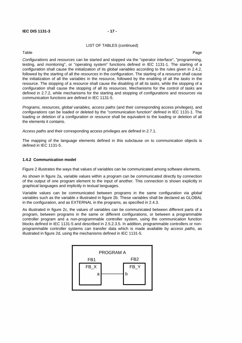
As shown in figure 2a, variable values within a program can be communicated directly by connection of the output of one program element to the input of another. This connection is shown explicitly in graphical languages and implicitly in textual languages.
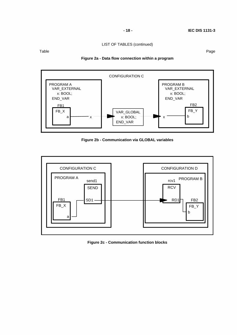
Variable values can be communicated between programs in the same configuration via global variables such as the variable x illustrated in figure 2b. These variables shall be declared as GLOBAL in the configuration, and as EXTERNAL in the programs, as specified in 2.4.3.
As illustrated in figure 2c, the values of variables can be communicated between different parts of a program, between programs in the same or different configurations, or between a programmable controller program and a non-programmable controller system, using the communication function blocks defined in IEC 1131-5 and described in 2.5.2.3.5. In addition, programmable controllers or non-programmable controller systems can transfer data which is made available by access paths, as illustrated in figure 2d, using the mechanisms defined in IEC 1131-5.
PROGRAM A
FB_Xa
FB1FB_Y
b
FB2
- 18 - IEC DIS 1131-3
LIST OF TABLES (continued)
Table Page
Figure 2a - Data flow connection within a program
PROGRAM A
FB_Xa
FB1
PROGRAM B
FB_Yb
FB2
x xVAR_GLOBAL
x: BOOL;END_VAR
VAR_EXTERNALx: BOOL;
END_VAR
VAR_EXTERNALx: BOOL;
END_VAR
CONFIGURATION C
Figure 2b - Communication via GLOBAL variables
PROGRAM A
FB_XFB1
CONFIGURATION C
SEND
send1
a
SD1FB_Y
b
FB2
CONFIGURATION D
RCV
rcv1
RD1
PROGRAM B
Figure 2c - Communication function blocks

IEC DIS 1131-3 - 19 -
LIST OF TABLES (continued)
Table Page
PROGRAM A
FB_XFB1
a Z
VAR_ACCESSCSX: P1.Z : REAL READ_ONLY;
PROGRAM B
FB_Yb
FB2
CONFIGURATION C CONFIGURATION D
READTO_FB2
RD1'CSX' VAR_1
P1
Figure 2d - Communication via access paths
NOTES
1 This figure is illustrative only. The graphical representation is not normative.
2 In these examples, configurations c and d are each considered to have a single resource.
3 The details of the communication function blocks are not shown in this figure. See 2.5.2.3.5 and IEC 1131-5.
4 As specified in 2.7, access paths can be declared on directly represented variables, global variables, or program input, output, or internal variables.
5 IEC 1131-5 specifies the means by which both PC and non-PC systems can use access paths for reading and writing of variables.
Figure 2 - Communication model
- 20 - IEC DIS 1131-3
LIST OF TABLES (continued)
Table Page
1.4.3 Programming model
The elements of programmable controller programming languages, and the subclauses in which they appear in this part, are classified as follows:
Data types (2.3) Program organization units (2.5)
Functions (2.5.1) Function blocks (2.5.2) Programs (2.5.3)
Sequential Function Chart (SFC) elements (2.6) Configuration elements (2.7)
Global variables (2.7.1) Resources (2.7.1) Tasks (2.7.2) Access paths (2.7.1)
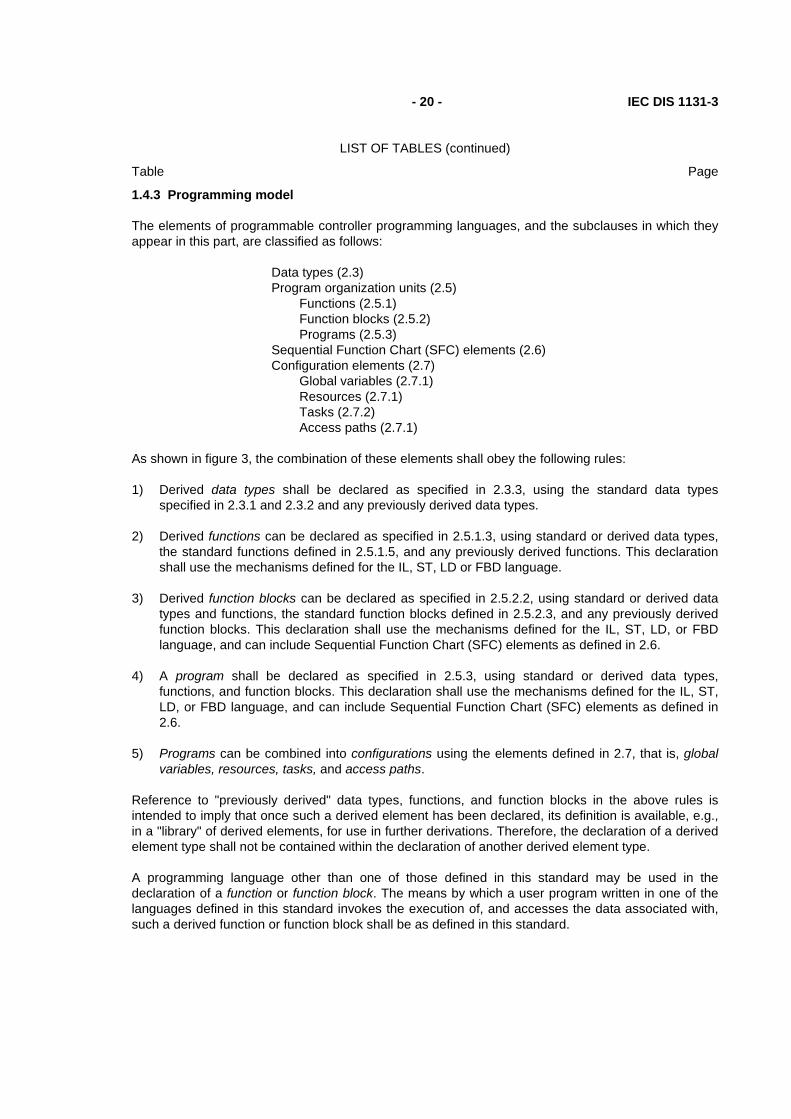
As shown in figure 3, the combination of these elements shall obey the following rules:
1) Derived data types shall be declared as specified in 2.3.3, using the standard data types specified in 2.3.1 and 2.3.2 and any previously derived data types.
2) Derived functions can be declared as specified in 2.5.1.3, using standard or derived data types, the standard functions defined in 2.5.1.5, and any previously derived functions. This declaration shall use the mechanisms defined for the IL, ST, LD or FBD language.
3) Derived function blocks can be declared as specified in 2.5.2.2, using standard or derived data types and functions, the standard function blocks defined in 2.5.2.3, and any previously derived function blocks. This declaration shall use the mechanisms defined for the IL, ST, LD, or FBD language, and can include Sequential Function Chart (SFC) elements as defined in 2.6.
4) A program shall be declared as specified in 2.5.3, using standard or derived data types, functions, and function blocks. This declaration shall use the mechanisms defined for the IL, ST, LD, or FBD language, and can include Sequential Function Chart (SFC) elements as defined in 2.6.
5) Programs can be combined into configurations using the elements defined in 2.7, that is, global variables, resources, tasks, and access paths.
Reference to "previously derived" data types, functions, and function blocks in the above rules is intended to imply that once such a derived element has been declared, its definition is available, e.g., in a "library" of derived elements, for use in further derivations. Therefore, the declaration of a derived element type shall not be contained within the declaration of another derived element type.
A programming language other than one of those defined in this standard may be used in the declaration of a function or function block. The means by which a user program written in one of the languages defined in this standard invokes the execution of, and accesses the data associated with, such a derived function or function block shall be as defined in this standard.

IEC DIS 1131-3 - 21 -
LIST OF TABLES (continued)
Table Page
LIBRARY ELEMENTS PRODUCTIONS DERIVED ELEMENTS
DATA TYPESStandard (2.3.1, 2.3.2)
Derived
FUNCTIONSStandard (2.5.1.5)
Derived
FUNCTION BLOCKSStandard (2.5.2.3)
Derived
PROGRAMS
RESOURCES
Declaration (2.5.1.3)IL, ST, LD, FBD
OTHERS
Declaration (2.5.2.2)IL, ST, LD, FBD
SFC elements (2.6)OTHERS
Declaration (2.5.3)IL, ST, LD, FBD
SFC elements (2.6)
Tasks (2.7.2)
Declaration (2.7.1)Global variables (2.7.1)
Access paths (2.7.1)
Deriveddatatypes
Derivedfunctions
Derivedfunctionblocks
PROGRAM
CONFIGURATION
Declaration (2.3.3)
(1)
(2)
(3)
(4)
(5)(2.5.3)
(2.7.1)
NOTES
1 The parenthesized numbers (1) to (5) refer to corresponding paragraphs in 1.4.3.
2 Data types are used in all productions. For clarity, the corresponding linkages are omitted in this figure.
Figure 3 - Combination of programmable controller language elements LD - Ladder Diagram (4.2) FBD - Function Block Diagram (4.3) IL - Instruction List (3.2) ST - Structured Text (3.3) OTHERS - Other programming languages (1.4.3)

- 22 - IEC DIS 1131-3
LIST OF TABLES (continued)
Table Page
1.5 Compliance
This subclause defines the requirements which shall be met by programmable controller systems and programs which claim compliance with this part of IEC 1131.
1.5.1 Programmable controller systems
A programmable controller system, as defined in IEC 1131-1, which claims to comply, wholly or partially, with the requirements of this part of IEC 1131 shall do so only as described below.
A compliance statement shall be included in the documentation accompanying the system, or shall be produced by the system itself. The form of the compliance statement shall be:
"This system complies with the requirements of IEC 1131-3, for the following language features:",
followed by a set of compliance tables in the following format:
Table title
Table No. Feature No. Features description
... ... ...
Table and feature numbers and descriptions are to be taken from the tables given in the relevant subclauses of this part of IEC 1131. Table titles are to be taken from the following table.
Table title For features in: Common elements Clause 2
Common textual elements Subclause 3.1
IL language elements Subclauses 3.2.1 to 3.2.3
ST language elements Subclauses 3.3.1 to 3.3.2.4
Common graphical elements Subclauses 4.1 to 4.1.4
LD language elements Subclauses 4.2 to 4.2.6
FBD language elements Subclauses 4.3 to 4.3.3
A programmable controller system complying with the requirements of this part with respect to a language defined in this part:
a) shall not require the inclusion of substitute or additional language elements in order to accomplish any of the features specified in this part;
b) shall be accompanied by a document that specifies the values of all implementation-dependent parameters as listed in annex D;
IEC DIS 1131-3 - 23 -
LIST OF TABLES (continued)
Table Page
c) shall be able to determine whether or not a user's language element violates any requirement of this part, where such a violation is not designated an error in annex E, and report the result of this determination to the user. In the case where the system does not examine the whole program organization unit, the user shall be notified that the determination is incomplete whenever no violations have been detected in the portion of the program organization unit examined;

- 24 - IEC DIS 1131-3
LIST OF TABLES (continued)
Table Page
d) shall treat each user violation that is designated an error in annex E in at least one of the following ways:
1) there shall be a statement in an accompanying document that the error is not reported;
2) the system shall report during preparation of the program for execution that an occurrence of that error is possible;
3) the system shall report the error during preparation of the program for execution;
4) the system shall report the error during execution of the program and initiate appropriate system- or user-defined error handling procedures;
and if any violations that are designated as errors are treated in the manner described in d)1) above, then a note referencing each such treatment shall appear in a separate section of the accompanying document;
e) shall be accompanied by a document that separately describes any features accepted by the system that are prohibited or not specified in this part. Such features shall be described as being "extensions to the <language> language as defined in IEC 1131-3";
f) shall be able to process in a manner similar to that specified for errors any use of any such extension;
g) shall be able to process in a manner similar to that specified for errors any use of one of the implementation-dependent features specified in annex D;
h) shall not use any of the standard data type, function or function block names defined in this part for manufacturer-defined features whose functionality differs from that described in this part;
i) shall be accompanied by a document defining, in the form specified in annex A, the formal syntax of all textual language elements supported by the system.
The phrase "be able to" is used in this subclause to permit the implementation of a software switch with which the user may control the reporting of errors.
In cases where compilation or program entry is aborted due to some limitation of tables, etc., an incomplete determination of the kind "no violations were detected, but the examination is incomplete" will satisfy the requirements of this subclause.

IEC DIS 1131-3 - 25 -
LIST OF TABLES (continued)
Table Page
1.5.2 Programs
A programmable controller program complying with the requirements of IEC 1131-3:
a) shall use only those features specified in this part for the particular language used;
b) shall not use any features identified as extensions to the language;
c) shall not rely on any particular interpretation of implementation-dependent features.
The results produced by a complying program shall be the same when processed by any complying system which supports the features used by the program, except as these results are influenced by program execution timing, the use of implementation-dependent features (as listed in annex D) in the program, and the execution of error handling procedures.

- 26 - IEC DIS 1131-3
LIST OF TABLES (continued)
Table Page
2. Common elements
This clause defines textual and graphic elements which are common to all the programmable controller programming languages specified in this Part of IEC 1131.
2.1 Use of printed characters
2.1.1 Character set
Textual languages and textual elements of graphic languages shall be represented in terms of the "Basic code table" of the ISO/IEC 646 character set.
The encoding of characters from national or extended (8-bit) character sets shall be consistent with ISO/IEC 646.
The required character set shown as feature 1 in table 1 consists of all the characters in columns 3 to 7 of the "Basic code table" given as table 1 in ISO/IEC 646, except for lower-case letters and those character positions which are reserved or optionally available for use in national character sets.
The manufacturer shall support one option (a or b) for each of features (3a,b) to (6a,b) of table 1, according to the following rules:
- The "pound sign" (£) shall be used in place of the "number sign" (#) when the former occupies character position 2/3 of a national implementation of the ISO/IEC 646 character set.
- The "currency sign" shall be used in place of the "dollar sign" ($) when the former occupies character position 2/4 of a national implementation of the ISO/IEC 646 character set.
- When the 7/12 character position in the ISO/IEC 646 character set is used by another character in a national set, the "exclamation mark" (!) at position 2/1 shall be used to represent vertical lines.
- For delimitation of subscripts, the left and right parentheses "( )" shall be used in place of the left and right brackets "[ ]" when the latter occupy character positions of a national implementation of the ISO/IEC 646 character set.
NOTE - The use of characters from national character sets is a typical extension of this standard.

IEC DIS 1131-3 - 27 -
LIST OF TABLES (continued)
Table Page
Table 1 - Character set features
No. Description
1 Required character set (see 2.1.1)
2 Lower case characters 3a Number sign (#) OR 3b Pound sign (£) 4a Dollar sign ($) OR 4b Currency sign 5a 5b
Vertical bar (|) OR Exclamation mark (!)
6a 6b
Subscript delimiters: Left and right brackets "[ ]" OR Left and right parentheses "( )"
NOTE - When lower-case letters (feature 2) are supported, the case of letters shall not be significant in language elements (except within terminal symbols as defined in annexes A and B, comments as defined in 2.1.5, string literals as defined in 2.2.2, and variables of type STRING as defined in 2.3.1), e.g., the identifiers "abcd", "ABCD", and "aBCd" shall be interpreted identically.
2.1.2 Identifiers
An identifier is a string of letters, digits, and underline characters which shall begin with a letter or underline character.
Underlines shall be significant in identifiers, e.g., "A_BCD" and "AB_CD" shall be interpreted as different identifiers. Multiple leading or multiple embedded underlines are not allowed.
Identifiers shall not contain imbedded space (SP) characters.
At least six characters of uniqueness shall be supported in all systems which support the use of identifiers, e.g., "ABCDE1" shall be interpreted as different from "ABCDE2" in all such systems.
Identifier features and examples are shown in table 2.
Table 2 - Identifier features
No. Feature description Examples
1 Upper case and numbers IW215 IW215Z QX75 IDENT
2 Upper and lower case, numbers, embedded underlines
All the above plus: LIM_SW_5 LimSw5 abcd ab_Cd

- 28 - IEC DIS 1131-3
LIST OF TABLES (continued)
Table Page
3 Upper and lower case, numbers, leading or embedded underlines
All the above plus: _MAIN _12V7
IEC DIS 1131-3 - 29 -
LIST OF TABLES (continued)
Table Page
2.1.3 Keywords
Keywords are unique combinations of characters utilized as individual syntactic elements as defined in annex B. All keywords used in this part are listed in annex C. Keywords shall not contain imbedded spaces. The keywords listed in annex C shall not be used for any other purpose, e.g., variable names or extensions as defined in 1.5.1.
NOTE - National standards organizations can publish tables of translations of the keywords given in annex C.
2.1.4 Use of spaces
The user shall be allowed to insert one or more spaces (code position 2/0 in the ISO/IEC 646 character set) anywhere in the text of programmable controller programs except within keywords, literals, identifiers, directly represented variables as described in subclause 2.4.1.1, or delimiter combinations (e.g., for comments as defined below).
2.1.5 Comments
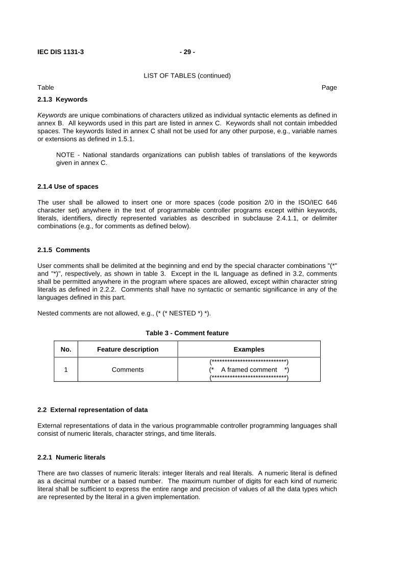
User comments shall be delimited at the beginning and end by the special character combinations "(*" and "*)", respectively, as shown in table 3. Except in the IL language as defined in 3.2, comments shall be permitted anywhere in the program where spaces are allowed, except within character string literals as defined in 2.2.2. Comments shall have no syntactic or semantic significance in any of the languages defined in this part.
Nested comments are not allowed, e.g., (* (* NESTED *) *).
Table 3 - Comment feature
No. Feature description Examples
1
Comments
(*****************************) (* A framed comment *) (*****************************)
2.2 External representation of data
External representations of data in the various programmable controller programming languages shall consist of numeric literals, character strings, and time literals.
2.2.1 Numeric literals
There are two classes of numeric literals: integer literals and real literals. A numeric literal is defined as a decimal number or a based number. The maximum number of digits for each kind of numeric literal shall be sufficient to express the entire range and precision of values of all the data types which are represented by the literal in a given implementation.

- 30 - IEC DIS 1131-3
LIST OF TABLES (continued)
Table Page
Single underline characters (_) inserted between the digits of a numeric literal shall not be significant. No other use of underline characters in numeric literals is allowed.
Decimal literals shall be represented in conventional decimal notation. Real literals shall be distinguished by the presence of a decimal point. An exponent indicates the integer power of ten by which the preceding number is to be multiplied to obtain the value represented. Decimal literals and their exponents can contain a preceding sign (+ or -).
Integer literals can also be represented in base 2, 8, or 16. The base shall be in decimal notation. For base 16, an extended set of digits consisting of the letters A through F shall be used, with the conventional significance of decimal 10 through 15, respectively. Based numbers shall not contain a leading sign (+ or -).
Boolean data shall be represented by integer literals with the value zero (0) or one (1), or the keywords FALSE or TRUE, respectively.
Numeric literal features and examples are shown in table 4.
Table 4 - Numeric literals
No. Feature description Examples
1 Integer literals -12 0 123_456 +986
2 Real literals -12.0 0.0 0.4560 3.14159_26
3
Real literals with exponents
-1.34E-12 or -1.34e-12 1.0E+6 or 1.0e+6 1.234E6 or 1.234e6
4 Base 2 literals 2#1111_1111 (255 decimal) 2#1110_0000 (240 decimal)
5 Base 8 literals 8#377 (255 decimal) 8#340 (240 decimal)
6 Base 16 literals 16#FF or 16#ff (255 decimal) 16#E0 or 16#e0 (240 decimal)
7 Boolean zero and one 0 1
8 Boolean FALSE and TRUE FALSE TRUE NOTE - The keywords FALSE and TRUE correspond to Boolean values of 0 and 1, respectively.
2.2.2 Character string literals
A character string literal is a sequence of zero or more characters prefixed and terminated by the single quote character ('). In character strings, the three-character combination of the dollar sign ($) followed by two hexadecimal digits shall be interpreted as the hexadecimal representation of the eight-bit character code, as shown in table 5. Additionally, two-character combinations beginning with the dollar sign shall be interpreted as shown in table 6 when they occur in character strings.

IEC DIS 1131-3 - 31 -
LIST OF TABLES (continued)
Table Page
Table 5 - Character string literal feature
No. Example Explanation
1 '' Empty string (length zero)
'A' String of length one containing the single character A
' ' String of length one containing the "space" character
'$'' String of length one containing the "single quote" character
'$R$L' '$0D$0A'
Strings of length two containing CR and LF characters
'$$1.00' String of length five which would print as "$1.00"
Table 6 - Two-character combinations in character strings
No. Combination Interpretation when printed
2 $$ Dollar sign
3 $' Single quote
4 $L or $l Line feed
5 $N or $n Newline
6 $P or $p Form feed (page)
7 $R or $r Carriage return
8 $T or $t Tab NOTE - The "newline" character provides an implementation-independent means of defining the end of a line of data for both physical and file I/O; for printing, the effect is that of ending a line of data and resuming printing at the beginning of the next line.
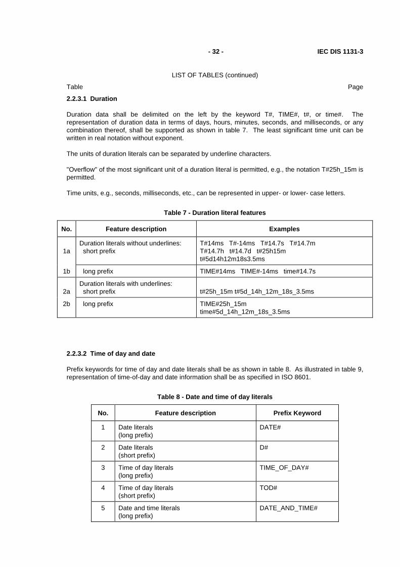
2.2.3 Time literals
The need to provide external representations for two distinct types of time-related data is recognized: duration data for measuring or controlling the elapsed time of a control event, and time of day data (which may also include date information) for synchronizing the beginning or end of a control event to an absolute time reference.
Duration and time of day literals shall be delimited on the left by the keywords defined in 2.2.3.1 and 2.2.3.2.
- 32 - IEC DIS 1131-3
LIST OF TABLES (continued)
Table Page
2.2.3.1 Duration
Duration data shall be delimited on the left by the keyword T#, TIME#, t#, or time#. The representation of duration data in terms of days, hours, minutes, seconds, and milliseconds, or any combination thereof, shall be supported as shown in table 7. The least significant time unit can be written in real notation without exponent.
The units of duration literals can be separated by underline characters.
"Overflow" of the most significant unit of a duration literal is permitted, e.g., the notation T#25h_15m is permitted.
Time units, e.g., seconds, milliseconds, etc., can be represented in upper- or lower- case letters.
Table 7 - Duration literal features
No. Feature description Examples
1a
Duration literals without underlines: short prefix
T#14ms T#-14ms T#14.7s T#14.7m T#14.7h t#14.7d t#25h15m t#5d14h12m18s3.5ms
1b long prefix TIME#14ms TIME#-14ms time#14.7s
2a
Duration literals with underlines: short prefix
t#25h_15m t#5d_14h_12m_18s_3.5ms
2b long prefix TIME#25h_15m time#5d_14h_12m_18s_3.5ms
2.2.3.2 Time of day and date
Prefix keywords for time of day and date literals shall be as shown in table 8. As illustrated in table 9, representation of time-of-day and date information shall be as specified in ISO 8601.
Table 8 - Date and time of day literals
No. Feature description Prefix Keyword
1 Date literals (long prefix)
DATE#
2 Date literals (short prefix)
D#
3 Time of day literals (long prefix)
TIME_OF_DAY#
4 Time of day literals (short prefix)
TOD#
5 Date and time literals (long prefix)
DATE_AND_TIME#

IEC DIS 1131-3 - 33 -
LIST OF TABLES (continued)
Table Page
6 Date and time literals (short prefix)
DT#

- 34 - IEC DIS 1131-3
LIST OF TABLES (continued)
Table Page
Table 9 - Examples of date and time of day literals
Long prefix notation Short prefix notation
DATE#1984-06-25 date#1984-06-25
D#1984-06-25 d#1984-06-25
TIME_OF_DAY#15:36:55.36 time_of_day#15:36:55.36
TOD#15:36:55.36 tod#15:36:55.36
DATE_AND_TIME#1984-06-25-15:36:55.36 date_and_time#1984-06-25-15:36:55.36
DT#1984-06-25-15:36:55.36 dt#1984-06-25-15:36:55.36
2.3 Data types
A number of elementary (pre-defined) data types are recognized by this standard. Additionally, generic data types are defined for use in the definition of overloaded functions (see 2.5.1.4). A mechanism for the user or manufacturer to specify additional data types is also defined.
2.3.1 Elementary data types
The elementary data types, keyword for each data type, number of bits per data element, and range of values for each elementary data type shall be as shown in table 10.

IEC DIS 1131-3 - 35 -
LIST OF TABLES (continued)
Table Page
Table 10 - Elementary data types
No. Keyword Data type Bits Range
1 BOOL Boolean 1 Note 8
2 SINT Short integer 8 Note 2
3 INT Integer 16 Note 2
4 DINT Double integer 32 Note 2
5 LINT Long integer 64 Note 2
6 USINT Unsigned short integer 8 Note 3
7 UINT Unsigned integer 16 Note 3
8 UDINT Unsigned double integer 32 Note 3
9 ULINT Unsigned long integer 64 Note 3
10 REAL Real numbers 32 Note 4
11 LREAL Long reals 64 Note 5
12 TIME Duration Note 1 Note 6
13 DATE Date (only) Note 1 Note 6
14 TIME_OF_DAY or TOD Time of day (only) Note 1 Note 6
15 DATE_AND_TIME or DT Date and time of Day Note 1 Note 6
16 STRING Variable-length character string Note 1 Note 7
17 BYTE Bit string of length 8 8 Note 7
18 WORD Bit string of length 16 16 Note 7
19 DWORD Bit string of length 32 32 Note 7
20 LWORD Bit string of length 64 64 Note 7
NOTES
1 The length of these data elements is implementation-dependent.
2 The range of values for variables of this data type is from -(2**(Bits-1)) to (2**(Bits-1))-1.
3 The range of values for variables of this data type is from 0 to (2**Bits)-1.
4 The range of values for variables of this data type shall be as defined in IEC 559 for the basic single width floating-point format.
5 The range of values for variables of this data type shall be as defined in IEC 559 for the basic double width floating-point format.
6 The range of values for variables of this data type is implementation-dependent.
7 A numeric range of values does not apply to this data type.
8 The possible values of variables of this data type shall be 0 and 1, corresponding to the keywords FALSE and TRUE, respectively.

- 36 - IEC DIS 1131-3
LIST OF TABLES (continued)
Table Page
2.3.2 Generic data types
In addition to the data types shown in table 10, the hierarchy of generic data types shown in table 11 can be used in the specification of inputs and outputs of standard functions and function blocks (see subclause 2.5.1.4). Generic data types are identified by the prefix "ANY".
Table 11 - Hierarchy of generic data types
ANY ANY_NUM
ANY_REAL LREAL REAL
ANY_INT LINT, DINT, INT, SINT ULINT, UDINT, UINT, USINT
ANY_BIT LWORD, DWORD, WORD, BYTE, BOOL
STRING ANY_DATE
DATE_AND_TIME DATE TIME_OF_DAY
TIME Derived (see notes)
NOTES
1 The use of generic data types in non-standard functions or function blocks is beyond the scope of this Standard.
2 The generic type of a subrange derived type (feature 3 of table 12) shall be ANY_INT.
3 The generic type of a directly derived type (feature 1 of table 12) shall be the same as the generic type of the elementary type from which it is derived.
4 The generic type of all other derived types defined in table 12 shall be ANY.
2.3.3 Derived data types
2.3.3.1 Declaration
Derived (i.e., user- or manufacturer-specified) data types can be declared using the TYPE...END_TYPE textual construction shown in table 12. These derived data types can then be used, in addition to the elementary data types defined in 2.3.1, in variable declarations as defined in 2.4.3.

IEC DIS 1131-3 - 37 -
LIST OF TABLES (continued)
Table Page
An enumerated data type declaration specifies that the value of any data element of that type can only take on one of the values given in the associated list of identifiers, as illustrated in table 12.
A subrange declaration specifies that the value of any data element of that type can only take on values between and including the specified upper and lower limits, as illustrated in table 12.
A STRUCT declaration specifies that data elements of that type shall contain sub-elements of specified types which can be accessed by the specified names. For instance, an element of data type ANALOG_CHANNEL_CONFIGURATION as declared in table 12 will contain a RANGE sub-element of type ANALOG_SIGNAL_RANGE, a MIN_SCALE sub-element of type ANALOG_DATA, and a MAX_SCALE element of type ANALOG_DATA.
An ARRAY declaration specifies that a sufficient amount of data storage shall be allocated for each element of that type to store all the data which can be indexed by the specified index subrange(s). Thus, any element of type ANALOG_16_INPUT_CONFIGURATION as shown in table 12 contains (among other elements) sufficient storage for 16 CHANNEL elements of type ANALOG_CHANNEL_CONFIGURATION. Mechanisms for access to array elements are defined in 2.4.1.2.
2.3.3.2 Initialization
The default initial value of an enumerated data type shall be the first identifier in the associated enumeration list, or a value specified by the assignment operator ":=". For instance, as shown in tables 12 and 14, the default initial values of elements of data types ANALOG_SIGNAL_TYPE and ANALOG_SIGNAL_RANGE are SINGLE_ENDED and UNIPOLAR_1_5V, respectively.
For data types with subranges, the default initial values shall be the first (lower) limit of the subrange, unless otherwise specified by an assignment operator. For instance, as declared in table 12, the default initial value of elements of type ANALOG_DATA is -4095, while the default initial value for the FILTER_PARAMETER sub-element of elements of type ANALOG_16_INPUT_CONFIGURATION is zero. In contrast, the default initial value of elements of type ANALOG_DATAZ as declared in table 14 is zero.
For other derived data types, the default initial values, unless specified otherwise by the use of the assignment operator ":=" in the TYPE declaration, shall be the default initial values of the underlying elementary data types as defined in table 13. Further examples of the use of the assignment operator for initialization are given in 2.4.2.
The default maximum length of elements of type STRING shall be an implementation-dependent value unless specified otherwise by a parenthesized maximum length (which shall not exceed the implementation-dependent default value) in the associated declaration. For example, if type STR10 is declared by
TYPE STR10 : STRING[10] := 'ABCDEF'; END_TYPE the maximum length, default initial value, and default initial length of data elements of type STR10 are 10 characters, 'ABCDEF', and 6 characters, respectively.

- 38 - IEC DIS 1131-3
LIST OF TABLES (continued)
Table Page
Table 12 - Data type declaration features
No. Feature/textual example
1 Direct derivation from elementary types, e.g.: TYPE R : REAL ; END_TYPE
2 Enumerated data types, e.g.: TYPE ANALOG_SIGNAL_TYPE : (SINGLE_ENDED, DIFFERENTIAL) ; END_TYPE
3 Subrange data types, e.g.: TYPE ANALOG_DATA : INT (-4095..4095) ; END_TYPE
4 Array data types, e.g.: TYPE ANALOG_16_INPUT_DATA : ARRAY [1..16] OF ANALOG_DATA ; END_TYPE
5 Structured data types, e.g.: TYPE ANALOG_CHANNEL_CONFIGURATION : STRUCT RANGE : ANALOG_SIGNAL_RANGE ; MIN_SCALE : ANALOG_DATA ; MAX_SCALE : ANALOG_DATA ; END_STRUCT ; ANALOG_16_INPUT_CONFIGURATION : STRUCT SIGNAL_TYPE : ANALOG_SIGNAL_TYPE ; FILTER_PARAMETER : SINT (0..99) ; CHANNEL : ARRAY [1..16] OF ANALOG_CHANNEL_CONFIGURATION ; END_STRUCT ; END_TYPE NOTE - For examples of the use of these types in variable declarations, see 2.3.3.3, 2.4.1.2, and table 17.
Table 13 - Default initial values
Data type(s) Initial value
BOOL, SINT, INT, DINT, LINT 0
USINT, UINT, UDINT, ULINT 0
BYTE, WORD, DWORD, LWORD 0
REAL, LREAL 0.0
TIME T#0S
DATE D#0001-01-01
TIME_OF_DAY TOD#00:00:00
DATE_AND_TIME DT#0001-01-01-00:00:00

IEC DIS 1131-3 - 39 -
LIST OF TABLES (continued)
Table Page
STRING '' (the empty string)

- 40 - IEC DIS 1131-3
LIST OF TABLES (continued)
Table Page
Table 14 - Data type initial value declaration features
No. Feature/textual example
1 Initialization of directly derived types, e.g.: TYPE FREQ : REAL := 50.0 ; END_TYPE
2 Initialization of enumerated data types, e.g.: TYPE ANALOG_SIGNAL_RANGE : (BIPOLAR_10V, (* -10 to +10 VDC *) UNIPOLAR_10V, (* 0 to +10 VDC *) UNIPOLAR_1_5V, (* + 1 to + 5 VDC *) UNIPOLAR_0_5V, (* 0 to + 5 VDC *) UNIPOLAR_4_20_MA, (* + 4 to +20 mADC *) UNIPOLAR_0_20_MA (* 0 to +20 mADC *) ) := UNIPOLAR_1_5V ; END_TYPE
3 Initialization of subrange data types, e.g.: TYPE ANALOG_DATAZ : INT (-4095..4095) := 0 ; END_TYPE
4 Initialization of array data types, e.g.: TYPE ANALOG_16_INPUT_DATAI : ARRAY [1..16] OF ANALOG_DATA := [8(-4095), 8(4095)] ; END_TYPE
5 Initialization of structured data type elements, e.g.: TYPE ANALOG_CHANNEL_CONFIGURATIONI : STRUCT RANGE : ANALOG_SIGNAL_RANGE ; MIN_SCALE : ANALOG_DATA := -4095 ; MAX_SCALE : ANALOG_DATA := 4095 ; END_STRUCT ; END_TYPE
6 Initialization of derived structured data types, e.g.: TYPE ANALOG_CHANNEL_CONFIGZ : ANALOG_CHANNEL_CONFIGURATIONI(MIN_SCALE := 0, MAX_SCALE := 4000); END_TYPE
2.3.3.3 Usage
The usage of variables which are declared (as defined in 2.4.3.1) to be of derived data types shall conform to the following rules:
(1) A single-element variable, as defined in 2.4.1.1, of a derived type, can be used anywhere that a variable of its "parent's" type can be used, e.g. variables of the types R and FREQ as shown in tables 12 and 14 can be used anywhere that a variable of type REAL could be used, and variables of type ANALOG_DATA can be used anywhere that a variable of type INT could be used.
This rule can be applied recursively. For example, given the declarations below, the variable R3 of type R2 can be used anywhere a variable of type REAL can be used:

IEC DIS 1131-3 - 41 -
LIST OF TABLES (continued)
Table Page
TYPE R1 : REAL := 1.0 ; END_TYPE TYPE R2 : R1 ; END_TYPE VAR R3: R2; END_VAR
(2) An element of a multi-element variable, as defined in 2.4.1.2, can be used anywhere the "parent" type can be used, e.g., given the declaration of ANALOG_16_INPUT_DATA in table 12 and the declaration
VAR INS : ANALOG_16_INPUT_DATA ; END_VAR
the variables INS[1] through INS[16] can be used anywhere that a variable of type INT could be used.
This rule can also be applied recursively, e.g., given the declarations of ANALOG_16_INPUT_CONFIGURATION, ANALOG_CHANNEL_CONFIGURATION, and ANALOG_DATA in table 12 and the declaration
VAR CONF : ANALOG_16_INPUT_CONFIGURATION ; END_VAR
the variable CONF.CHANNEL[2].MIN_SCALE can be used anywhere that a variable of type INT could be used.
2.4 Variables
In contrast to the external representations of data described in 2.2, variables provide a means of identifying data objects whose contents may change, e.g., data associated with the inputs, outputs, or memory of the programmable controller. A variable can be declared to be one of the elementary types defined in 2.3.1, or one of the derived types which are declared as defined in 2.3.3.1.
2.4.1 Representation
2.4.1.1 Single-element variables
A single-element variable is defined as a variable which represents a single data element of one of the elementary types defined in 2.3.1; a derived enumeration or subrange type as defined in 2.3.3.1; or a derived type whose "parentage", as defined recursively in 2.3.3.3, is traceable to an elementary, enumeration or subrange type. This subclause defines the means of representing such variables symbolically, or alternatively in a manner which directly represents the association of the data element with physical or logical locations in the programmable controller's input, output, or memory structure.
Identifiers, as defined in 2.1.2, shall be used for symbolic representation of variables.
Direct representation of a single-element variable shall be provided by a special symbol formed by the concatenation of the percent sign "%" (position 2/5 in the ISO/IEC 646 code table), a location prefix and a size prefix from table 15, and one or more unsigned integers, separated by periods “.”.
Examples of directly represented variables are:
%QX75 and %Q75 Output bit 75 %IW215 Input word location 215 %QB7 Output byte location 7 %MD48 Double word at memory location 48

- 42 - IEC DIS 1131-3
LIST OF TABLES (continued)
Table Page
%IW2.5.7.1 See explanation below
The manufacturer shall specify the correspondence between the direct representation of a variable and the physical or logical location of the addressed item in memory, input or output. When a direct representation is extended with additional integer fields separated by periods, it shall be interpreted as a hierarchical physical or logical address with the leftmost field representing the highest level of the hierarchy, with successively lower levels appearing to the right. For instance, the variable %IW2.5.7.1 may represent the first "channel" (word) of the seventh "module" in the fifth "rack" of the second "I/O bus" of a programmable controller system.
The use of hierarchical addressing to permit a program in one programmable controller system to access data in another programmable controller shall be considered a language extension.
The use of directly represented variables is only permitted in programs, as defined in 2.5.3, and in configurations and resources as defined in 2.7.1. The maximum number of levels of hierarchical addressing is an implementation-dependent parameter.
Table 15 - Location and size prefix features for directly represented variables
No. Prefix Meaning Default data type
1 I Input location
2 Q Output location
3 M Memory location
4 X Single bit size BOOL
5 None Single bit size BOOL
6 B Byte (8 bits) size BYTE
7 W Word (16 bits) size WORD
8 D Double word (32 bits) size DWORD
9 L Long (quad) word (64 bits) size LWORD NOTE - National standards organizations can publish tables of translations of these prefixes.
2.4.1.2 Multi-element variables
The multi-element variable types defined in this standard are arrays and structures.
An array is a collection of data elements of the same data type referenced by one or more subscripts enclosed in brackets and separated by commas. In the ST language defined in subclause 3.3, a subscript shall be an expression yielding a value corresponding to one of the sub-types of generic type ANY_INT as defined in table 11. The form of subscripts in the IL language defined in subclause 3.2, and the graphic languages defined in clause 4, is restricted to single-element variables or integer literals.
An example of the use of array variables in the ST language as defined in 3.3 is:
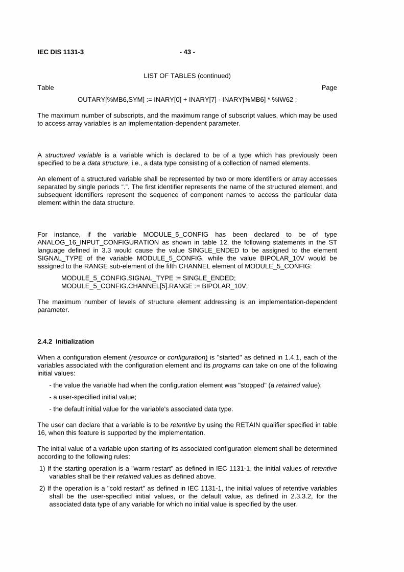
IEC DIS 1131-3 - 43 -
LIST OF TABLES (continued)
Table Page
OUTARY[%MB6,SYM] := INARY[0] + INARY[7] - INARY[%MB6] * %IW62 ;
The maximum number of subscripts, and the maximum range of subscript values, which may be used to access array variables is an implementation-dependent parameter.
A structured variable is a variable which is declared to be of a type which has previously been specified to be a data structure, i.e., a data type consisting of a collection of named elements.
An element of a structured variable shall be represented by two or more identifiers or array accesses separated by single periods “.”. The first identifier represents the name of the structured element, and subsequent identifiers represent the sequence of component names to access the particular data element within the data structure.
For instance, if the variable MODULE_5_CONFIG has been declared to be of type ANALOG_16_INPUT_CONFIGURATION as shown in table 12, the following statements in the ST language defined in 3.3 would cause the value SINGLE_ENDED to be assigned to the element SIGNAL_TYPE of the variable MODULE_5_CONFIG, while the value BIPOLAR_10V would be assigned to the RANGE sub-element of the fifth CHANNEL element of MODULE_5_CONFIG:
MODULE_5_CONFIG.SIGNAL_TYPE := SINGLE_ENDED; MODULE_5_CONFIG.CHANNEL[5].RANGE := BIPOLAR_10V;
The maximum number of levels of structure element addressing is an implementation-dependent parameter.
2.4.2 Initialization
When a configuration element (resource or configuration) is "started" as defined in 1.4.1, each of the variables associated with the configuration element and its programs can take on one of the following initial values:
- the value the variable had when the configuration element was "stopped" (a retained value);
- a user-specified initial value;
- the default initial value for the variable's associated data type.
The user can declare that a variable is to be retentive by using the RETAIN qualifier specified in table 16, when this feature is supported by the implementation.
The initial value of a variable upon starting of its associated configuration element shall be determined according to the following rules:
1) If the starting operation is a "warm restart" as defined in IEC 1131-1, the initial values of retentive variables shall be their retained values as defined above.
2) If the operation is a "cold restart" as defined in IEC 1131-1, the initial values of retentive variables shall be the user-specified initial values, or the default value, as defined in 2.3.3.2, for the associated data type of any variable for which no initial value is specified by the user.

- 44 - IEC DIS 1131-3
LIST OF TABLES (continued)
Table Page
3) Non-retained variables shall be initialized to the user-specified initial values, or to the default value, as defined in 2.3.3.2, for the associated data type of any variable for which no initial value is specified by the user.
4) Variables which represent inputs of the programmable controller system as defined in IEC 1131-1 shall be initialized in an implementation-dependent manner.
2.4.3 Declaration
Each programmable controller program organization unit type declaration (i.e., each declaration of a program, function, or function block, as defined in 2.5) shall contain at its beginning at least one declaration part which specifies the types (and, if necessary, the physical or logical location) of the variables used in the organization unit. This declaration part shall have the textual form of one of the keywords VAR, VAR_INPUT, or VAR_OUTPUT as defined in table 16, followed in the case of VAR by zero or one occurrence of the qualifier RETAIN or the qualifier CONSTANT, and in the case of VAR_OUTPUT by zero or one occurrence of the qualifier RETAIN, followed by one or more declarations separated by semicolons and terminated by the keyword END_VAR. When a programmable controller supports the declaration by the user of initial values for variables, this declaration shall be accomplished in the declaration part(s) as defined in this subclause.
The scope (range of validity) of the declarations contained in the declaration part shall be local to the program organization unit in which the declaration part is contained. That is, the declared variables shall not be accessible to other program organization units except by explicit parameter passing via variables which have been declared as inputs or outputs of those units. The one exception to this rule is the case of variables which have been declared to be global, as defined in 2.7.1. Such variables are only accessible to a program organization unit via a VAR_EXTERNAL declaration. The type of a variable declared in a VAR_EXTERNAL block shall agree with the type declared in the VAR_GLOBAL block of the associated program, configuration or resource.
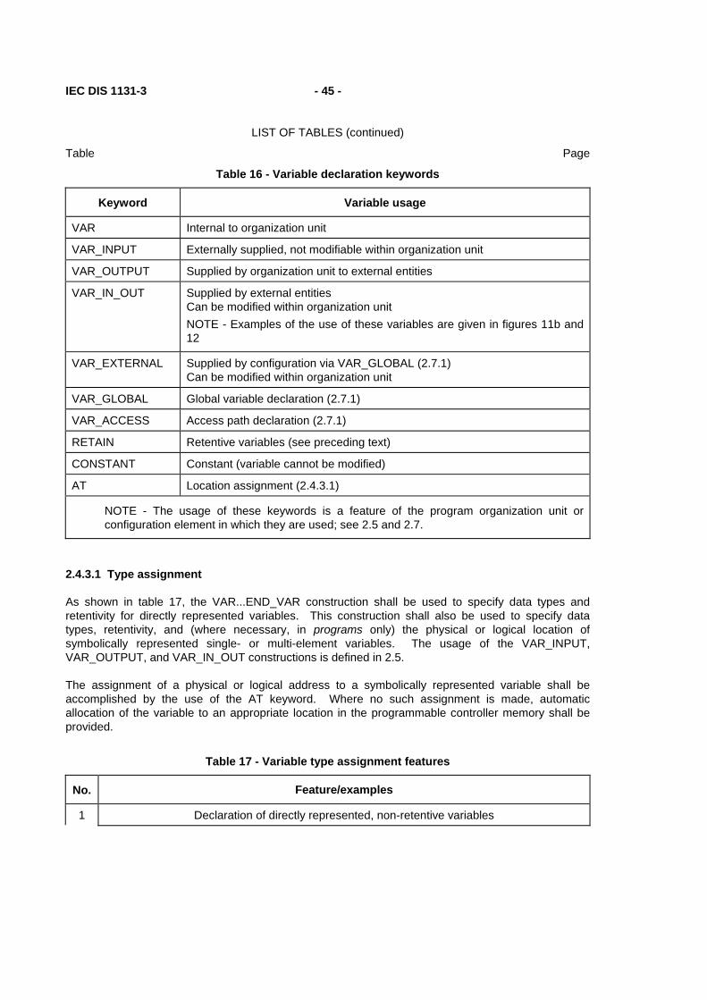
IEC DIS 1131-3 - 45 -
LIST OF TABLES (continued)
Table Page
Table 16 - Variable declaration keywords
Keyword Variable usage
VAR Internal to organization unit
VAR_INPUT Externally supplied, not modifiable within organization unit
VAR_OUTPUT Supplied by organization unit to external entities
VAR_IN_OUT Supplied by external entities Can be modified within organization unit NOTE - Examples of the use of these variables are given in figures 11b and 12
VAR_EXTERNAL Supplied by configuration via VAR_GLOBAL (2.7.1) Can be modified within organization unit
VAR_GLOBAL Global variable declaration (2.7.1)
VAR_ACCESS Access path declaration (2.7.1)
RETAIN Retentive variables (see preceding text)
CONSTANT Constant (variable cannot be modified)
AT Location assignment (2.4.3.1)
NOTE - The usage of these keywords is a feature of the program organization unit or configuration element in which they are used; see 2.5 and 2.7.
2.4.3.1 Type assignment
As shown in table 17, the VAR...END_VAR construction shall be used to specify data types and retentivity for directly represented variables. This construction shall also be used to specify data types, retentivity, and (where necessary, in programs only) the physical or logical location of symbolically represented single- or multi-element variables. The usage of the VAR_INPUT, VAR_OUTPUT, and VAR_IN_OUT constructions is defined in 2.5.
The assignment of a physical or logical address to a symbolically represented variable shall be accomplished by the use of the AT keyword. Where no such assignment is made, automatic allocation of the variable to an appropriate location in the programmable controller memory shall be provided.
Table 17 - Variable type assignment features
No. Feature/examples
1 Declaration of directly represented, non-retentive variables
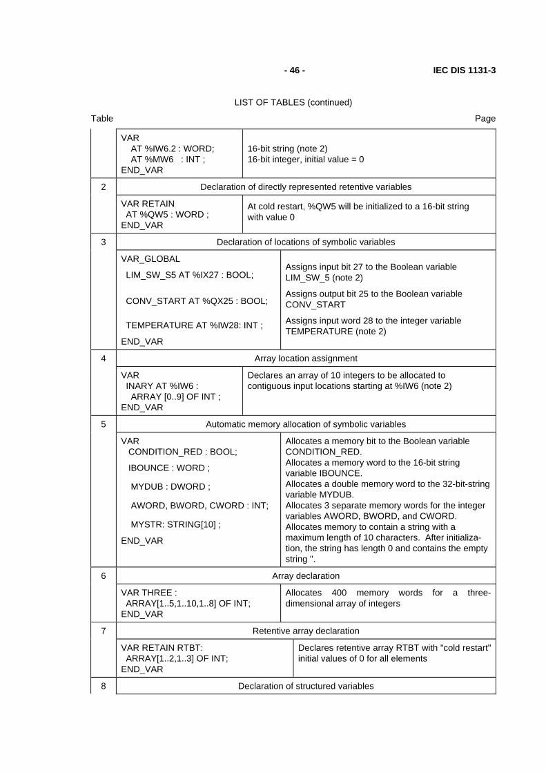
- 46 - IEC DIS 1131-3
LIST OF TABLES (continued)
Table Page
VAR AT %IW6.2 : WORD; AT %MW6 : INT ; END_VAR
16-bit string (note 2) 16-bit integer, initial value = 0
2 Declaration of directly represented retentive variables
VAR RETAIN AT %QW5 : WORD ; END_VAR
At cold restart, %QW5 will be initialized to a 16-bit string with value 0
3 Declaration of locations of symbolic variables
VAR_GLOBAL
LIM_SW_S5 AT %IX27 : BOOL;
CONV_START AT %QX25 : BOOL;
TEMPERATURE AT %IW28: INT ;
END_VAR
Assigns input bit 27 to the Boolean variable LIM_SW_5 (note 2)
Assigns output bit 25 to the Boolean variable CONV_START
Assigns input word 28 to the integer variable TEMPERATURE (note 2)
4 Array location assignment
VAR INARY AT %IW6 : ARRAY [0..9] OF INT ; END_VAR
Declares an array of 10 integers to be allocated to contiguous input locations starting at %IW6 (note 2)
5 Automatic memory allocation of symbolic variables
VAR CONDITION_RED : BOOL;
IBOUNCE : WORD ;
MYDUB : DWORD ;
AWORD, BWORD, CWORD : INT;
MYSTR: STRING[10] ;
END_VAR
Allocates a memory bit to the Boolean variable CONDITION_RED. Allocates a memory word to the 16-bit string variable IBOUNCE. Allocates a double memory word to the 32-bit-string variable MYDUB. Allocates 3 separate memory words for the integer variables AWORD, BWORD, and CWORD. Allocates memory to contain a string with a maximum length of 10 characters. After initializa-tion, the string has length 0 and contains the empty string ''.
6 Array declaration
VAR THREE : ARRAY[1..5,1..10,1..8] OF INT; END_VAR
Allocates 400 memory words for a three-dimensional array of integers
7 Retentive array declaration
VAR RETAIN RTBT: ARRAY[1..2,1..3] OF INT; END_VAR
Declares retentive array RTBT with "cold restart" initial values of 0 for all elements
8 Declaration of structured variables
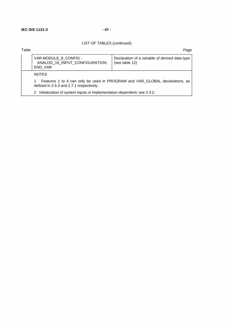
IEC DIS 1131-3 - 47 -
LIST OF TABLES (continued)
Table Page
VAR MODULE_8_CONFIG : ANALOG_16_INPUT_CONFIGURATION; END_VAR
Declaration of a variable of derived data type (see table 12)
NOTES
1 Features 1 to 4 can only be used in PROGRAM and VAR_GLOBAL declarations, as defined in 2.5.3 and 2.7.1 respectively.
2 Initialization of system inputs is implementation-dependent; see 2.4.2.

- 48 - IEC DIS 1131-3
LIST OF TABLES (continued)
Table Page
2.4.3.2 Initial value assignment
The VAR...END_VAR construction shown in table 18 shall be used to specify initial values of directly represented variables. This construction shall also be used to assign initial values of symbolically represented single- or multi-element variables (the usage of the VAR_INPUT, VAR_OUTPUT, and VAR_IN_OUT constructions is defined in 2.5).
Initial values cannot be given in VAR_EXTERNAL declarations.
During initialization of arrays, the rightmost subscript of an array shall vary most rapidly with respect to filling the array from the list of initialization variables.
Parentheses can be used as a repetition factor in array initialization lists, e.g., "2(1,2,3)" is equivalent to the initialization sequence "1,2,3,1,2,3".
If the number of initial values given in the initialization list exceeds the number of array entries, the excess (rightmost) initial values shall be ignored. If the number of initial values is less than the number of array entries, the remaining array entries shall be filled with the default initial values for the corresponding data type. In either case, the user shall be warned of this condition during preparation of the program for execution.
When a variable is declared to be of a derived, structured data type as defined in 2.3.3.1, initial values for the elements of the variable can be declared in a parenthesized list following the data type identifier, as shown in table 18. Elements for which initial values are not listed in the initial value list shall have the default initial values declared for those elements in the data type declaration.
Table 18 - Variable initial value assignment features
No. Feature/examples
1 Initialization of directly represented, non-retentive variables
VAR AT %QX5.1 : BOOL :=1; AT %MW6 : INT := 8 ; END_VAR
Boolean type, initial value =1 Initializes a memory word to integer 8
2 Initialization of directly represented retentive variables
VAR RETAIN AT %QW5 : WORD := 16#FF00 ; END_VAR
At cold restart, the 8 most significant bits of the 16-bit string at output word 5 are to be initialized to 1 and the 8 least significant bits to 0
3 Location and initial value assignment to symbolic variables
VAR VALVE_POS AT %QW28 : INT := 100; END_VAR
Assigns output word 28 to the integer variable VALVE_POS, with an initial value of 100
4 Array location assignment and initialization
VAR OUTARY AT %QW6 : ARRAY [0..9] OF INT := [10(1)] ; END_VAR
Declares an array of 10 integers to be allocated to contiguous output locations starting at %QW6, each with an initial value of 1
5 Initialization of symbolic variables

IEC DIS 1131-3 - 49 -
LIST OF TABLES (continued)
Table Page
VAR MYBIT : BOOL := 1 ; OKAY : STRING[10] := 'OK'; END_VAR
Allocates a memory bit to the Boolean variable MYBIT with an initial value of 1. Allocates memory to contain a string with a maximum length of 10 characters. After initialization, the string has length 2 and contains the two-byte sequence of characters 'OK' in the ISO/IEC 646 character set, in an order appropriate for printing as a character string.
6 Array initialization
VAR BITS : ARRAY[0..7] OF BOOL := [1,1,0,0,0,1,0,0] ;
TBT : ARRAY [1..2,1..3] OF INT := [1,2,3(4),6] ; END_VAR
Allocates 8 memory bits to contain initial values BITS[0]:= 1, BITS[1] := 1,..., BITS[6]:= 0, BITS[7] := 0.
Allocates a 2-by-3 integer array TBT with initial values TBT[1,1]:=1, TBT[1,2]:=2, TBT[1,3]:=4, TBT[2,1]:=4, TBT[2,2]:=4, TBT[2,3]:=6.
7 Retentive array declaration and initialization
VAR RETAIN RTBT : ARRAY(1..2,1..3) OF INT := [1,2,3(4)]; END_VAR
Declares retentive array RTBT with "cold restart" initial values of: RTBT[1,1] := 1, RTBT[1,2] := 2, RTBT[1,3] := 4, RTBT[2,1] := 4, RTBT[2,2] := 4, RTBT[2,3] := 0.
8 Initialization of structured variables
VAR MODULE_8_CONFIG : ANALOG_16_INPUT_CONFIGURATION (SIGNAL_TYPE := DIFFERENTIAL, CHANNEL := [4((RANGE := UNIPOLAR_1_5)), (RANGE := BIPOLAR_10_V, MIN_SCALE := 0, MAX_SCALE := 500)]) ; END_VAR
Initialization of a variable of derived data type (see table 12)
NOTE - This example illustrates the declaration of a non-default initial value for the fifth element of the CHANNEL array of the variable MODULE_8_CONFIG.
9 Initialization of constants
VAR CONSTANT PI : REAL := 3.141592 ; END_VAR
NOTE - Features 1 to 4 can only be used in PROGRAM and VAR_GLOBAL declarations, as defined in 2.5.3 and 2.7.1 respectively.
2.5 Program organization units
The program organization units defined in this Part of IEC 1311 are the function, function block, and program. These program organization units can be delivered by the manufacturer, or programmed by the user by the means defined in this part of the standard.
Program organization units shall not be recursive; that is, the invocation of a program organization unit shall not cause the invocation of another program organization unit of the same type.

- 50 - IEC DIS 1131-3
LIST OF TABLES (continued)
Table Page
2.5.1 Functions
For the purposes of programmable controller programming languages, a function is defined as a program organization unit which, when executed, yields exactly one data element (which can be multi-valued, e.g., an array or structure), and whose invocation can be used in textual languages as an operand in an expression. For example, the SIN and COS functions could be used as shown in figure 4.
a) Z := SIN(X)*COS(Y) + COS(X)*SIN(Y) ;
b)
+-----+ X----+--| SIN |--+ | +-----+ | | | +---+ +---+ | +-----+ +--| * |-----| + |---Z Y--+----| COS |-----| | +--| | | | +-----+ +---+ | +---+ | | | | | +-----+ +---+ | | +--| COS |-----| * |--+ | +-----+ +--| | | | +---+ | +-----+ | +----| SIN |--+ +-----+
Figure 4 - Examples of function usage a) Structured Text (ST) language; see subclause 3.3 b) Function Block Diagram (FBD) language; see subclause 4.3
Functions shall contain no internal state information, i.e., invocation of a function with the same arguments (input parameters) shall always yield the same value (output).
Any function type which has already been declared can be used in the declaration of another program organization unit, as shown in figure 3.

IEC DIS 1131-3 - 51 -
LIST OF TABLES (continued)
Table Page
2.5.1.1 Representation
Functions and their invocation can be represented either graphically or textually.
In the graphic languages defined in clause 4 of this part, functions shall be represented as graphic blocks according to the following rules:
1) The form of the block shall be rectangular or square.
2) The size and proportions of the block may vary depending on the number of inputs and other information to be displayed.
3) The direction of processing through the block shall be from left to right (input parameters on the left and output parameter on the right).
4) The function name or symbol, as specified below, shall be located inside the block.
5) Provision shall be made for formal input parameter names appearing at the inside left of the block when the block represents:
- one of the standard functions defined in subclause 2.5.1.5, when the given graphical form includes the formal parameter names; or
- any additional function declared as specified in subclause 2.5.1.3.
6) Since the name of the function is used for the assignment of its output value as specified in 2.5.1.3, no formal output parameter name shall be shown at the right side of the block.
7) Actual parameter connections shall be shown by signal flow lines.
8) Negation of Boolean signals shall be shown by placing an open circle just outside of the input or output line intersection with the block. In the ISO/IEC 646 character set, this shall be represented by the upper case alphabetic "O", as shown in table 19.
9) The output of a graphically represented function shall be represented by a single line at the right side of the block, even though the output may be a multi-element variable.
Table 19 - Graphical negation of Boolean signals
No. Feature Representation
1
Negated input
+---+ ---O| |--- +---+
2
Negated output
+---+ ----| |O--- +---+
NOTE - If either of these features is supported for functions, it shall also be supported for function blocks as defined in 2.5.2, and vice versa.

- 52 - IEC DIS 1131-3
LIST OF TABLES (continued)
Table Page
Figure 5 illustrates both the graphical and equivalent textual use of functions, including the use of a standard function (ADD) with no defined formal parameter names, and another standard function (SHL) with defined formal parameter names.

IEC DIS 1131-3 - 53 -
LIST OF TABLES (continued)
Table Page
Example Explanation
+-----+ | ADD | B---| |---A C---| | D---| | +-----+
Graphical use of "ADD" function (See 2.5.1.5.2) (FBD language; see 4.3) (No formal parameter names)
A := ADD(B,C,D); Textual use of "ADD" function (ST language; see 3.3)
+-----+ | SHL | B---|IN |---A C---|N | +-----+
Graphical use of "SHL" function (See 2.5.1.5.3) (FBD language; see 4.3) (Formal parameter names)
A := SHL(IN := B,N := C); Textual use of "SHL" function (ST language; see 3.3)
Figure 5 - Use of formal parameter names
Features for the textual invocation of functions are defined in table 19a. Textual invocation of a function shall consist of the function name followed by a list of comma-separated parameters. In the ST language defined in subclause 3.3, this list shall be delimited on the left and right by parentheses. In features 1 and 3 of table 19a, this list shall contain exactly the same number of parameters, in exactly the same order and types as given in the function definition. In features 1 and 2 of table 19a, this list has the form of a set of assignments of actual values to the formal parameter names. In feature 2 of table 19a, any parameter not assigned a value in the list shall have the default value, if any, assigned in the function specification, or the default value for the associated data type.
TABLE 19a - Textual invocation of functions
No. Feature Example
Parameter assignment
Parameter order
Number of parameters
1 yes fixed fixed A := LIMIT(MN:=1, IN:= B, MX:= 5);
2 yes any any A := LIMIT(IN := B, MX := 5) ;
3 no fixed fixed A := ADD(B,C,D) ;
NOTES:
1 Feature #3 is required for invocation of any of the standard functions defined in subclause 2.5.1.5 without formal names for one or more input parameters.

- 54 - IEC DIS 1131-3
LIST OF TABLES (continued)
Table Page
2 In the example given in feature #2, the MN parameter will have the default value 0 (zero).
2.5.1.2 Execution control
As shown in table 20, an additional Boolean "EN" (Enable) input and "ENO" (Enable Out) output shall be used with functions in the LD language defined in 4.2, and their use shall also be possible in the FBD language defined in this part. These variables are considered to be available in every function according to the implicit declarations
VAR_INPUT EN: BOOL := 1; END_VAR VAR_OUTPUT ENO: BOOL; END_VAR
When these variables are used, the execution of the operations defined by the function shall be controlled according to the following rules:
1) If the value of EN is FALSE (0) when the function is invoked, the operations defined by the function body shall not be executed and the value of "ENO" shall be reset to FALSE (0) by the programmable controller system.
2) Otherwise, the value of ENO shall be set to TRUE (1) by the programmable controller system, and the operations defined by the function body shall be executed. These operations can include the assignment of a Boolean value to ENO.
3) If one of the errors defined in annex E occurs during the execution of one of the standard functions defined in 2.5.1.5, the ENO output of that function shall be reset to FALSE (0) by the programmable controller system.
NOTE - The use of the ENO output is an allowable exception to the rule that the execution of a function yields exactly one output.

IEC DIS 1131-3 - 55 -
LIST OF TABLES (continued)
Table Page
Table 20 - Use of EN input and ENO output
No. Feature Example
1
Use of "EN" and "ENO" Required for LD (Ladder Diagram) language (see 4.2)
+-------+ | | ADD_EN | + | ADD_OK | +---||---|EN ENO|---( )---+ | | | | | A---| |---C | | B---| | | +-------+ |
2
Use of "EN" and "ENO" Optional for FBD (Function Block Diagram) language (see 4.3)
+-------+ | + | ADD_EN--|EN ENO|---ADD_OK A---| |---C B---| | +-------+
3
FBD without "EN" and "ENO"
+-----+ A---| + |---C B---| | +-----+
2.5.1.3 Declaration
A function shall be declared textually or graphically.
As illustrated in figure 6, the textual declaration of a function shall consist of the following elements:
1) The keyword FUNCTION, followed by an identifier specifying the name of the function being declared, a colon (:), and the data type of the value to be returned by the function;
2) A VAR_INPUT...END_VAR construct as defined in 2.4.2, specifying the names and types of the function's input parameters;
3) A VAR...END_VAR construct, if required, specifying the names and types of the function's internal variables;
4) A function body, written in one of the languages defined in this part, or another programming language as defined in 1.4.3, which specifies the operations to be performed upon the input parameter(s) in order to assign one or more values to a variable with the same name as the function, which represents the value to be returned by the function;
5) The terminating keyword END_FUNCTION.
As illustrated in figure 6, the graphic declaration of a function shall consist of the following elements:
1) The bracketing keywords FUNCTION...END_FUNCTION or a graphical equivalent;
2) A graphic specification of the function name and the names and types of the function's inputs and output;

- 56 - IEC DIS 1131-3
LIST OF TABLES (continued)
Table Page
3) A specification of the names and types of the internal variables used in the function, e.g., using the VAR...END_VAR construct;
4) A function body as defined above.
a) FUNCTION SIMPLE_FUN : REAL
VAR_INPUT A,B : REAL ; (* External interface specification *) C : REAL := 1.0; END_VAR
SIMPLE_FUN := A*B/C; (* Function body specification *)
END_FUNCTION
b) FUNCTION +-------------+ | SIMPLE_FUN | REAL----|A |----REAL REAL----|B |(* External interface specification *) REAL----|C | +-------------+ +---+ (* Function body specification *) A---| * | +---+ B---| |---| / |---SIMPLE_FUN +---+ | | C-----------| | +---+ END_FUNCTION
NOTE - In example a), the input variable C is given a default value of 1.0, as specified in 2.4.3.2, to avoid a "division by zero" error if the input is not specified when the func-tion is invoked, for example, if a graphical input to the function is left unconnected.
Figure 6 - Examples of function declarations a) Textual declaration in ST language (see 3.3) b) Graphical declaration in FBD language (see 4.3)
2.5.1.4 Typing, overloading, and type conversion
A standard function, function block type, operator, or instruction is said to be overloaded when it can operate on input data elements of various types within a generic type designator as defined in 2.3.2. For instance, an overloaded addition function on generic type ANY_NUM can operate on data of types LREAL, REAL, DINT, INT, and SINT.
When a programmable controller system supports an overloaded standard function, function block type, operator, or instruction, this standard function, function block type, operator, or instruction shall apply to all data types of the given generic type which are supported by that system. For example, if a programmable controller system supports the overloaded function ADD and the data types SINT, INT, and REAL, then the system shall support the ADD function on inputs of type SINT, INT, and REAL.
When a function which normally represents an overloaded operator is to be typed, i.e., the types of its inputs and outputs restricted to a particular subtype, this shall be done by appending an "underline" character followed by the required type, as shown in table 21.
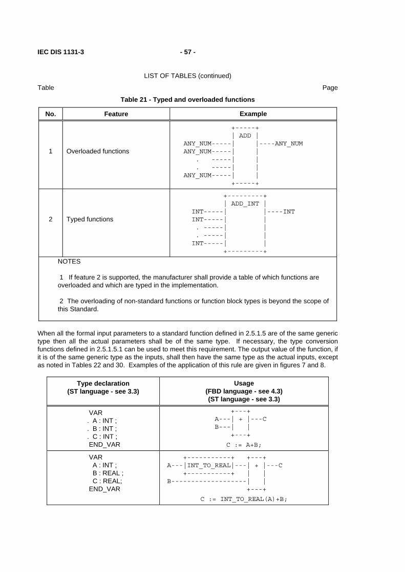
IEC DIS 1131-3 - 57 -
LIST OF TABLES (continued)
Table Page
Table 21 - Typed and overloaded functions
No. Feature Example
1
Overloaded functions
+-----+ | ADD | ANY_NUM-----| |----ANY_NUM ANY_NUM-----| | . -----| | . -----| | ANY_NUM-----| | +-----+
2
Typed functions
+---------+ | ADD_INT | INT-----| |----INT INT-----| | . -----| | . -----| | INT-----| | +---------+
NOTES
1 If feature 2 is supported, the manufacturer shall provide a table of which functions are overloaded and which are typed in the implementation.
2 The overloading of non-standard functions or function block types is beyond the scope of this Standard.
When all the formal input parameters to a standard function defined in 2.5.1.5 are of the same generic type then all the actual parameters shall be of the same type. If necessary, the type conversion functions defined in 2.5.1.5.1 can be used to meet this requirement. The output value of the function, if it is of the same generic type as the inputs, shall then have the same type as the actual inputs, except as noted in Tables 22 and 30. Examples of the application of this rule are given in figures 7 and 8.
Type declaration (ST language - see 3.3)
Usage (FBD language - see 4.3) (ST language - see 3.3)
VAR . A : INT ; . B : INT ; . C : INT ; END_VAR
+---+ A---| + |---C B---| | +---+
C := A+B;
VAR A : INT ; B : REAL ; C : REAL; END_VAR
+-----------+ +---+ A---|INT_TO_REAL|---| + |---C +-----------+ | | B-------------------| | +---+
C := INT_TO_REAL(A)+B;
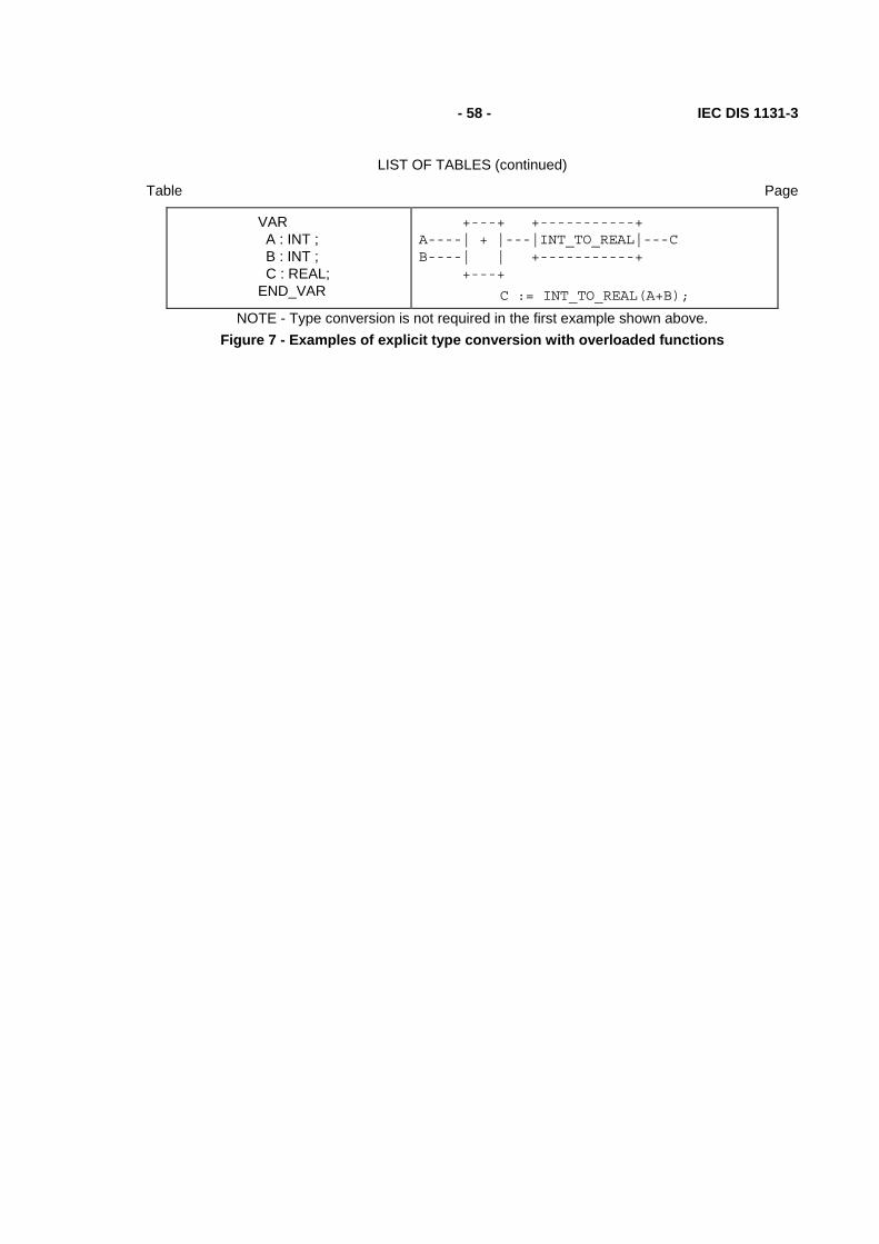
- 58 - IEC DIS 1131-3
LIST OF TABLES (continued)
Table Page
VAR A : INT ; B : INT ; C : REAL; END_VAR
+---+ +-----------+ A----| + |---|INT_TO_REAL|---C B----| | +-----------+ +---+
C := INT_TO_REAL(A+B);
NOTE - Type conversion is not required in the first example shown above. Figure 7 - Examples of explicit type conversion with overloaded functions

IEC DIS 1131-3 - 59 -
LIST OF TABLES (continued)
Table Page
Type declaration
(ST language - see 3.3) Usage
(FBD language - see 4.3) (ST language - see 3.3)
VAR A : INT ; B : INT ; C : INT ; END_VAR
+---------+ A---| ADD_INT |---C B---| | +---------+
C := ADD_INT(A,B);
VAR A : INT ; B : REAL ; C : REAL; END_VAR
+-----------+ +----------+ A---|INT_TO_REAL|---| ADD_REAL |---C +-----------+ | | B-------------------| | +----------+
C := ADD_REAL(INT_TO_REAL(A),B);
VAR A : INT ; B : INT ; C : REAL; END_VAR
+---------+ +-----------+ A---| ADD_INT |---|INT_TO_REAL|---C | | +-----------+ B---| | +---------+
C := INT_TO_REAL(ADD_INT(A,B));
NOTE - Type conversion is not required in the first example shown above. Figure 8 - Examples of explicit type conversion with typed functions
2.5.1.5 Standard functions
Definitions of functions common to all programmable controller programming languages are given in this subclause. Where graphical representations of standard functions are shown in this subclause, equivalent textual declarations may be written as specified in 2.5.1.3.
A standard function specified in this subclause to be extensible is allowed to have a variable number of inputs, and shall be considered as applying the indicated operation to each input in turn, e.g., extensible addition shall give as its output the sum of all its inputs. The maximum number of inputs of an extensible function is an implementation-dependent parameter.
2.5.1.5.1 Type conversion functions
As shown in table 22, type conversion functions shall have the form *_TO_**, where "*" is the type of the input variable IN, and "**" the type of the output variable OUT, e.g., INT_TO_REAL.

- 60 - IEC DIS 1131-3
LIST OF TABLES (continued)
Table Page
Table 22 - Type conversion function features
No. Graphical form Usage example Notes
1
+---------+ * ---| *_TO_** |--- ** +---------+ (*) - Input data type, e.g., INT (**) - Output data type, e.g.,REAL (*_TO_**) - Function name, e.g., INT_TO_REAL
A := INT_TO_REAL(B) ;
1 2 5
2
+-------+ ANY_REAL---| TRUNC |---ANY_INT +-------+
A := TRUNC(B) ;
3
3
+-----------+ ANY_BIT--| BCD_TO_** |---ANY_INT +-----------+
A := BCD_TO_INT(B) ;
4
4
+----------+ ANY_INT--| *_TO_BCD |---ANY_BIT +----------+
A := INT_TO_BCD(B) ;
4
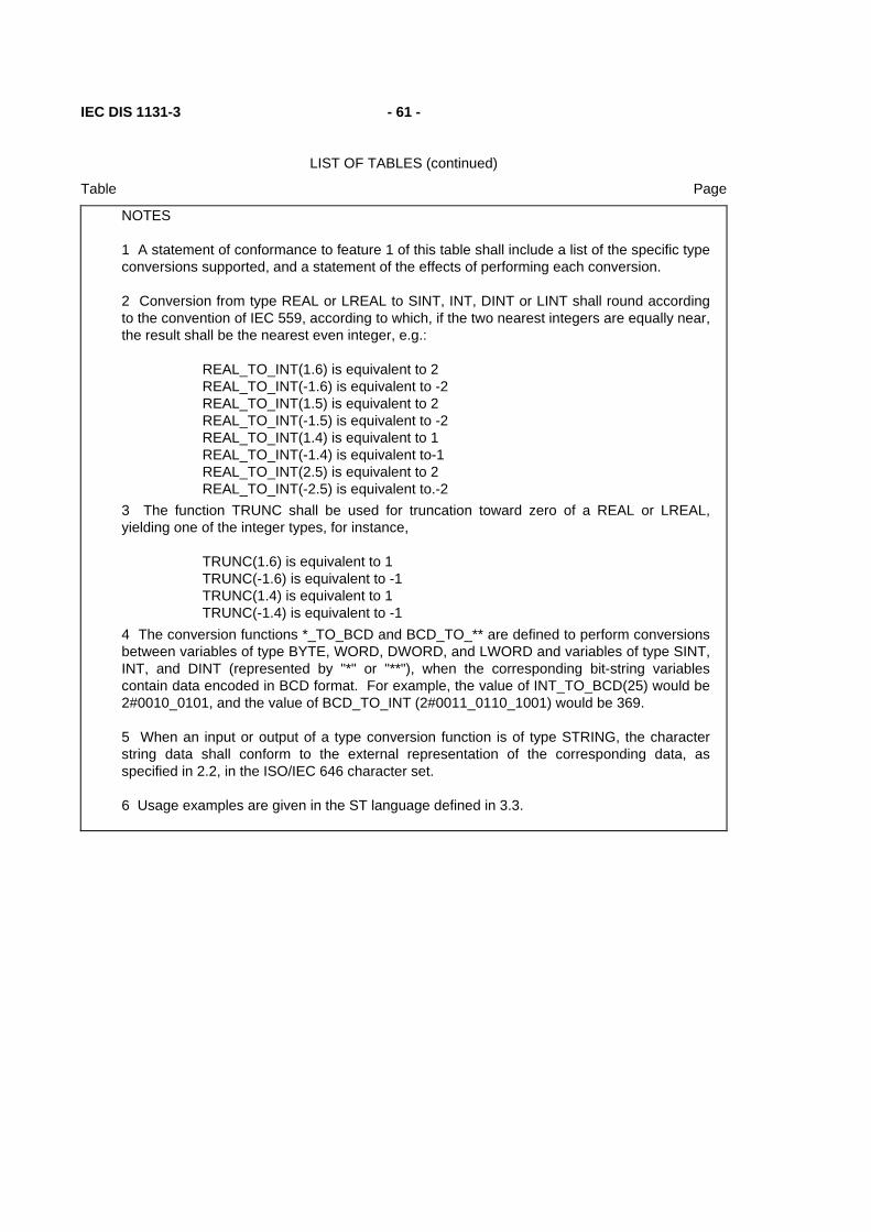
IEC DIS 1131-3 - 61 -
LIST OF TABLES (continued)
Table Page
NOTES
1 A statement of conformance to feature 1 of this table shall include a list of the specific type conversions supported, and a statement of the effects of performing each conversion.
2 Conversion from type REAL or LREAL to SINT, INT, DINT or LINT shall round according to the convention of IEC 559, according to which, if the two nearest integers are equally near, the result shall be the nearest even integer, e.g.:
REAL_TO_INT(1.6) is equivalent to 2 REAL_TO_INT(-1.6) is equivalent to -2 REAL_TO_INT(1.5) is equivalent to 2 REAL_TO_INT(-1.5) is equivalent to -2 REAL_TO_INT(1.4) is equivalent to 1 REAL_TO_INT(-1.4) is equivalent to-1 REAL_TO_INT(2.5) is equivalent to 2 REAL_TO_INT(-2.5) is equivalent to.-2
3 The function TRUNC shall be used for truncation toward zero of a REAL or LREAL, yielding one of the integer types, for instance,
TRUNC(1.6) is equivalent to 1 TRUNC(-1.6) is equivalent to -1 TRUNC(1.4) is equivalent to 1 TRUNC(-1.4) is equivalent to -1
4 The conversion functions *_TO_BCD and BCD_TO_** are defined to perform conversions between variables of type BYTE, WORD, DWORD, and LWORD and variables of type SINT, INT, and DINT (represented by "*" or "**"), when the corresponding bit-string variables contain data encoded in BCD format. For example, the value of INT_TO_BCD(25) would be 2#0010_0101, and the value of BCD_TO_INT (2#0011_0110_1001) would be 369.
5 When an input or output of a type conversion function is of type STRING, the character string data shall conform to the external representation of the corresponding data, as specified in 2.2, in the ISO/IEC 646 character set.
6 Usage examples are given in the ST language defined in 3.3.

- 62 - IEC DIS 1131-3
LIST OF TABLES (continued)
Table Page
2.5.1.5.2 Numerical functions
The standard graphical representation, function names, input and output variable types, and function descriptions of functions of a single numeric variable shall be as defined in table 23. These functions shall be overloaded on the defined generic types, and can be typed as defined in 2.5.1.4. For these functions, the types of the input and output shall be the same.
The standard graphical representation, function names and symbols, and descriptions of arithmetic functions of two or more variables shall be as shown in table 24. These functions shall be overloaded on all numeric types, and can be typed as defined in 2.5.1.4.
Table 23 - Standard functions of one numeric variable
Graphical form Usage example
+---------+ * ---| ** |--- * +---------+ (*) - Input/Output (I/O) type (**) - Function name
A := SIN(B) ;
(ST language - see 3.3)
No. Function
name
I/O type Description
General functions
1 ABS ANY_NUM Absolute value
2 SQRT ANY_REAL Square root
Logarithmic functions
3 LN ANY_REAL Natural logarithm
4 LOG ANY_REAL Logarithm base 10
5 EXP ANY_REAL Natural exponential
Trigonometric functions
6 SIN ANY_REAL Sine of input in radians
7 COS ANY_REAL Cosine in radians
8 TAN ANY_REAL Tangent in radians
9 ASIN ANY_REAL Principal arc sine
10 ACOS ANY_REAL Principal arc cosine
11 ATAN ANY_REAL Principal arc tangent

IEC DIS 1131-3 - 63 -
LIST OF TABLES (continued)
Table Page
Table 24 - Standard arithmetic functions
Graphical form Usage example
+-----+ ANY_NUM ---| *** |--- ANY_NUM ANY_NUM ---| | . ---| | . ---| | ANY_NUM ---| | +-----+
(***) - Name or Symbol
A := ADD(B,C,D) ;
or A := B+C+D ;
No. Name Symbol
(note 1)
Description
(notes 2 and 8)
Extensible arithmetic functions
12 ADD + OUT := IN1 + IN2 + ... + INn
13 MUL * OUT := IN1 * IN2 * ... * INn
Non-extensible arithmetic functions
14 SUB - OUT := IN1 - IN2
15 DIV / OUT := IN1 / IN2 (note 5)
16 MOD OUT := IN1 modulo IN2 (note 3)
17 EXPT ** Exponentiation: OUT := IN1IN2 (note 4)
18 MOVE := OUT := IN (note 9)

- 64 - IEC DIS 1131-3
LIST OF TABLES (continued)
Table Page
NOTES
1 These symbols are suitable for use as operators in textual languages, as shown in tables 52 and 55.
2 The notations IN1, IN2, ..., INn refer to the inputs in top-to-bottom order; OUT refers to the output.
3 IN1 and IN2 shall be of generic type ANY_INT for this function. The result of evaluating this function shall be the equivalent of executing the following statements in the ST language as defined in 3.3: IF (IN2 = 0) THEN OUT := 0 ; ELSE OUT := IN1 - (IN1/IN2)*IN2 ; END_IF
4 IN1 shall be of type ANY_REAL, and IN2 of type ANY_NUM for this function. The output shall be of the same type as IN1.
5 The result of division of integers shall be an integer of the same type with truncation toward zero, for instance, 7/3 = 2 and (-7)/3 = -2.
6 When the named representation of a function is supported, this shall be indicated by the suffix "n" in the compliance statement. For example, "12n" represents the notation "ADD".
7 When the symbolic representation of a function is supported, this shall be indicated by the suffix "s" in the compliance statement. For example, "12s" represents the notation "+".
8 Usage examples and descriptions are given in the ST language defined in Clause 3.3.
9 The MOVE function has exactly one input (IN) of type any and one output (OUT) of type ANY.

IEC DIS 1131-3 - 65 -
LIST OF TABLES (continued)
Table Page
2.5.1.5.3 Bit string functions
The standard graphical representation, function names and descriptions of shift functions for a single bit-string variable shall be as defined in table 25. These functions shall be overloaded on all bit-string types, and can be typed as defined in 2.5.1.4.
The standard graphical representation, function names and symbols, and descriptions of bitwise Boolean functions shall be as defined in table 26. These functions shall be extensible, except for NOT, and overloaded on all bit-string types, and can be typed as defined in 2.5.1.4.
Table 25 - Standard bit shift functions
Graphical form Usage example
+-----+ | *** | ANY_BIT ---|IN |--- ANY_BIT UINT ------|N | +-----+ (***) - Function Name
A := SHL(IN:=B, N:=5) ;
(ST language - see 3.3 )
No. Name Description
1 SHL OUT := IN left-shifted by N bits, zero-filled on right
2 SHR OUT := IN right-shifted by N bits, zero-filled on left
3 ROR OUT := IN right-rotated by N bits, circular
4 ROL OUT := IN left-rotated by N bits, circular
NOTE - The notation "OUT" refers to the function output.
2.5.1.5.4 Selection and comparison functions
Selection and comparison functions shall be overloaded on all data types. The standard graphical representations, function names and descriptions of selection functions shall be as shown in table 27.
The standard graphical representation, function names and symbols,and descriptions of comparison functions shall be as defined in table 28. All comparison functions (except NE) shall be extensible.
Comparisons of bit string data shall be made bitwise from the most significant to the least significant bit, and shorter bit strings shall be considered to be filled on the left with zeros when compared to longer bit strings; that is, comparison of bit string variables shall have the same result as comparison of unsigned integer variables.

- 66 - IEC DIS 1131-3
LIST OF TABLES (continued)
Table Page
Table 26 - Standard bitwise Boolean functions
Graphical form Usage examples
+-----+ ANY_BIT ---| *** |--- ANY_BIT ANY_BIT ---| | . ---| | . ---| | ANY_BIT ---| | +-----+
(***) - Name or symbol
A := AND(B,C,D) ;
or
A := B & C & D ;
No. Name Symbol Description
5 AND & (note 1) OUT := IN1 & IN2 & ... & INn
6 OR >=1 (note 2) OUT := IN1 OR IN2 OR ... OR INn
7 XOR =2k+1 (note 2) OUT := IN1 XOR IN2 XOR ... XOR INn
8 NOT OUT := NOT IN1 (Note 4) NOTES
1 This symbol is suitable for use as an operator in textual languages, as shown in tables 52 and 55.
2 This symbol is not suitable for use as an operator in textual languages.
3 The notations IN1, IN2, ..., INn refer to the inputs in top-to-bottom order; OUT refers to the output.
4 Graphic negation of signals of type BOOL can also be accomplished as shown in table 19.
5 When the named representation of a function is supported, this shall be indicated by the suffix "n" in the compliance statement. For example, "5n" represents the notation "AND".
6 When the symbolic representation of a function is supported, this shall be indicated by the suffix "s" in the compliance statement. For example, "5s" represents the notation "&".
7 Usage examples and descriptions are given in the ST language defined in 3.3.

IEC DIS 1131-3 - 67 -
LIST OF TABLES (continued)
Table Page
Table 27 - Standard selection functions
No. Graphical form Explanation/example
1
+-----+ | SEL | BOOL----|G |----ANY ANY-----|IN0 | ANY-----|IN1 | +-----+
Binary selection: OUT := IN0 if G = 0 OUT := IN1 if G = 1
Example: A := SEL(G:=0,IN0:=X,IN1:=5) ;
2a
+-----+ | MAX | (Note 1)---| |----ANY : ---| | (Note 1)---| | +-----+
Extensible maximum function: OUT := MAX (IN1,IN2, ...,INn)
Example: A := MAX(B,C,D) ;
2b
+-----+ | MIN | (Note 1)---| |----ANY : ---| | (Note 1)---| | +-----+
Extensible minimum function: OUT := MIN (IN1,IN2, ...,INn)
Example: A := MIN(B,C,D) ;
3
+-------+ | LIMIT | (Note 1)--|MN |----ANY (Note 1)--|IN | (Note 1)--|MX | +-------+
Limiter: OUT := MIN(MAX(IN,MN),MX)
Example: A := LIMIT(IN:=B,MN:=0,MX:=5);
4
+-----+ | MUX | ANY_INT---|K |----ANY ANY---| | : ---| | ANY---| | +-----+
Extensible multiplexer: Select one of "N" inputs depending on input K
Example: A := MUX(0, B, C, D);
would have the same effect as A := B ;
NOTES
1 These inputs can be of type ANY_BIT, ANY_NUM, STRING, ANY_DATE, or TIME. The type conversion rules given in 2.5.1.4 shall be followed for these inputs.
2 The notations IN1, IN2, ..., INn refer to the inputs in top-to-bottom order; OUT refers to the output.
3 Usage examples and descriptions are given in the ST language defined in 3.3.

- 68 - IEC DIS 1131-3
LIST OF TABLES (continued)
Table Page
Table 28 - Standard comparison functions
Graphical form Usage examples
+-----+ (Note 1)--| *** |--- BOOL : --| | (Note 1)--| | +-----+ (***) - Name or Symbol
A := GT(B,C,D) ;
or
A := (B>C) & (C>D) ;
No. Name Symbol Description
5 GT > Decreasing sequence: OUT := (IN1>IN2) & (IN2>IN3) & ... & (INn-1 > INn)
6 GE >= Monotonic sequence: OUT := (IN1>=IN2) & (IN2>=IN3) & ... & (INn-1 >= INn)
7 EQ = Equality: OUT := (IN1=IN2) & (IN2=IN3) & ... & (INn-1 = INn)
8 LE <= Monotonic sequence: OUT := (IN1<=IN2) & (IN2<=IN3) & ... & (INn-1 <= INn)
9 LT < Increasing sequence: OUT := (IN1<IN2) & (IN2<IN3) & ... & (INn-1 < INn)
10 NE <> Inequality (non-extensible) OUT := (IN1 <> IN2)
NOTES
1 These inputs can be of type ANY_BIT, ANY_NUM, STRING, ANY_DATE, or TIME. The type conversion rules given in 2.5.1.4 shall be followed for these inputs.
2 The notations IN1, IN2, ..., INn refer to the inputs in top-to-bottom order; OUT refers to the output.
3 All the symbols shown in this table are suitable for use as operators in textual languages, as shown in tables 52 and 55.
4 When the named representation of a function is supported, this shall be indicated by the suffix "n" in the compliance statement. For example, "5n" represents the notation "GT".
5 When the symbolic representation of a function is supported, this shall be indicated by the suffix "s" in the compliance statement. For example, "5s" represents the notation ">".
6 Usage examples and descriptions are given in the ST language defined in 3.3.

IEC DIS 1131-3 - 69 -
LIST OF TABLES (continued)
Table Page
2.5.1.5.5 Character string functions
All the functions defined in 2.5.1.5.4 shall be applicable to character strings. For the purposes of comparison of two strings of unequal length, the shorter string shall be considered to be extended on the right to the length of the longer string by characters with the value zero. Comparison shall proceed from left to right, based on the numeric value of the character codes in the ISO/IEC 646 code table. For example, the character string 'Z' shall be greater than the character string 'AZ', and 'AZ' shall be greater than 'ABC'.
The standard graphical representations, function names and descriptions of additional functions of character strings shall be as shown in table 29. For the purpose of these operations, character positions within the string shall be considered to be numbered 1,2,...,L, beginning with the leftmost character position, where L is the length of the string.
Table 29 - Standard character string functions
No. Graphical form Explanation/example
1 +-----+ STRING---| LEN |---INT +-----+
String length function Example:
A := LEN('ASTRING') is equivalent to A := 7;
2 +------+ | LEFT | STRING----|IN |--STRING UINT------|L | +------+
Leftmost L characters of IN Example:
A := LEFT(IN:='ASTR',L:=3); is equivalent to
A := 'AST' ;
3 +-------+ | RIGHT | STRING----|IN |--STRING UINT------|L | +-------+
Rightmost L characters of IN Example:
A := RIGHT(IN:='ASTR',L:=3); is equivalent to
A := 'STR' ;
4 +-------+ | MID | STRING----|IN |--STRING UINT------|L | UINT------|P | +-------+
L characters of IN, beginning at the P-th
Example: A := MID(IN:='ASTR',L:=2,P:=2);
is equivalent to A := 'ST' ;
5 +--------+ | CONCAT | STRING---| |--STRING : ---| | STRING---| | +--------+
Extensible concatenation Example:
A := CONCAT('AB','CD','E') ; is equivalent to A := 'ABCDE' ;
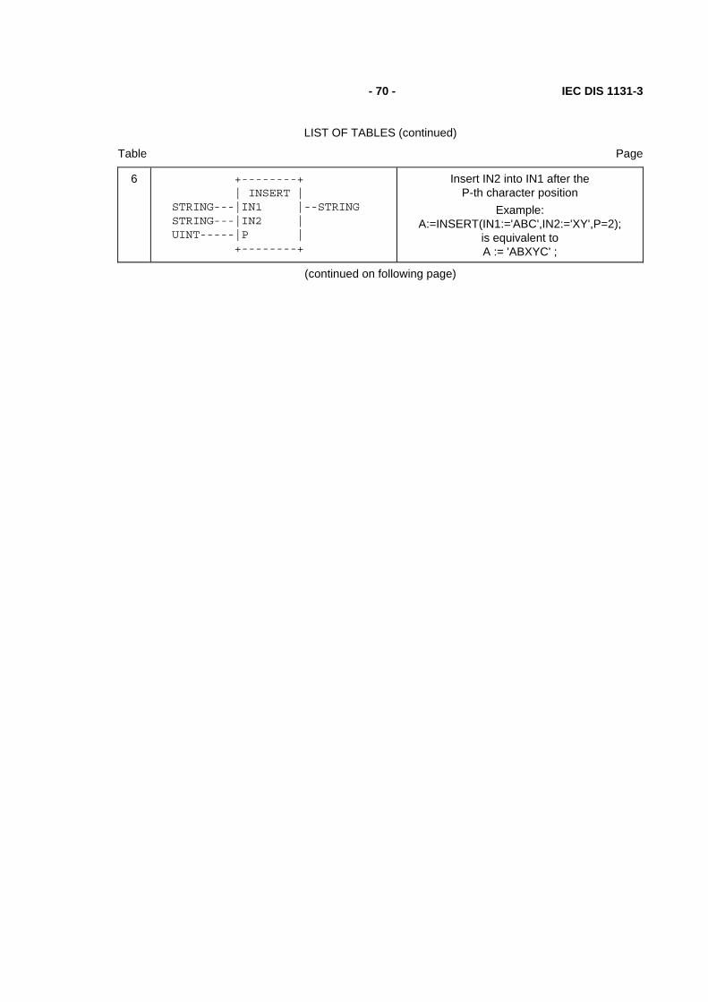
- 70 - IEC DIS 1131-3
LIST OF TABLES (continued)
Table Page
6 +--------+ | INSERT | STRING---|IN1 |--STRING STRING---|IN2 | UINT-----|P | +--------+
Insert IN2 into IN1 after the P-th character position
Example: A:=INSERT(IN1:='ABC',IN2:='XY',P=2);
is equivalent to A := 'ABXYC' ;
(continued on following page)

IEC DIS 1131-3 - 71 -
LIST OF TABLES (continued)
Table Page
Table 29 - Standard character string functions - continued No. Graphical form Explanation/example
7 +--------+ | DELETE | STRING---|IN |--STRING UINT-----|L | UINT-----|P | +--------+
Delete L characters of IN, beginning at the P-th character position
Example: A := DELETE(IN:='ABXYC',L:=2, P:=3) ;
is equivalent to A := 'ABC' ;
8 +---------+ | REPLACE | STRING---|IN1 |--STRING STRING---|IN2 | UINT-----|L | UINT-----|P | +---------+
Replace L characters of IN1 by IN2, starting at the P-th character position
Example: A := REPLACE(IN1:='ABCDE',IN2:='X',
L:=2, P:=3) ; is equivalent to A := 'ABXE' ;
9 +--------+ | FIND | STRING---|IN1 |---INT STRING---|IN2 | +--------+
Find the character position of the beginning of the first occurrence of IN2 in IN1. If no
occurrence of IN2 is found, then OUT := 0. Example:
A := FIND(IN1:='ABCBC',IN2:='BC') ; is equivalent to A := 2 ;
NOTE - The examples in this table are given in the Structured Text (ST) language defined in 3.3.
2.5.1.5.6 Functions of time data types
In addition to the comparison and selection functions defined in 2.5.1.5.4, the combinations of input and output time data types shown in table 30 shall be allowed with the associated functions.
2.5.1.5.7 Functions of enumerated data types
The selection and comparison functions listed in table 31 can be applied to inputs which are of an enumerated data type as defined in 2.3.3.1.

- 72 - IEC DIS 1131-3
LIST OF TABLES (continued)
Table Page
Table 30 - Functions of time data types
Numeric and concatenation functions
No. Name Symbol IN1 IN2 OUT
1 ADD + TIME TIME TIME
2 TIME_OF_DAY TIME TIME_OF_DAY
3 DATE_AND_TIME TIME DATE_AND_TIME
4 SUB - TIME TIME TIME
5 DATE DATE TIME
6 TIME_OF_DAY TIME TIME_OF_DAY
7 TIME_OF_DAY TIME_OF_DAY TIME
8 DATE_AND_TIME TIME DATE_AND_TIME
9 DATE_AND_TIME DATE_AND_TIME TIME
10 MUL * TIME ANY_NUM TIME
11 DIV / TIME ANY_NUM TIME
12 CONCAT DATE TIME_OF_DAY DATE_AND_TIME
Type conversion functions
13 14
DATE_AND_TIME_TO_TIME_OF_DAY DATE_AND_TIME_TO_DATE
NOTES
1 The type conversion functions shall have the effect of "extracting" the appropriate data, e.g., the ST language statements
X := DT#1986-04-28-08:40:00 ; Y := DATE_AND_TIME_TO_TIME_OF_DAY(X) ; W := DATE_AND_TIME_TO_DATE(X)
shall have the same result as the statements
X := DT#1986-04-28-08:40:00 ; W := DATE#1986-04-28 ; Y := TIME_OF_DAY#08:40:00
2 The provisions of NOTES 2-5 of table 28 apply to this table.
Table 31 - Functions of enumerated data types
No. Name Symbol Feature No. in Tables 27 and 28
1 SEL 1
2 MUX 4
3 EQ = 7
4 NE <> 10

IEC DIS 1131-3 - 73 -
LIST OF TABLES (continued)
Table Page
NOTE - The provisions of NOTES 2-5 of table 28 apply to this table.
2.5.2 Function blocks
For the purposes of programmable controller programming languages, a function block is a program organization unit which, when executed, yields one or more values. Multiple, named instances (copies) of a function block can be created. Each instance shall have an associated identifier (the instance name), and a data structure containing its output and internal variables, and, depending on the implementation, values of or references to its input parameters. All the values of the output variables and the necessary internal variables of this data structure shall persist from one execution of the function block to the next; therefore, invocation of a function block with the same arguments (input parameters) need not always yield the same output values.
Only the input and output parameters shall be accessible outside of an instance of a function block, i.e., the function block's internal variables shall be hidden from the user of the function block.
Execution of the operations of a function block shall be invoked as defined in clause 3 for textual languages, according to the rules of network evaluation given in clause 4 for graphic languages, or under the control of sequential function chart (SFC) elements as defined in 2.6.
Any function block type which has already been declared can be used in the declaration of another function block type or program type as shown in figure 3.
The scope of an instance of a function block shall be local to the program organization unit in which it is instantiated, unless it is declared to be global in a VAR_GLOBAL block as defined in 2.7.1.
As illustrated in 2.5.2.2, the instance name of a function block instance can be used as the input to a function or function block if declared as an input variable in a VAR_INPUT declaration, or as an input/output variable of a function block in a VAR_IN_OUT declaration, as defined in 2.4.3.
2.5.2.1 Representation
As illustrated in figure 9, an instance of a function block can be created textually, by declaring a data element using the declared function block type in a VAR...END_VAR construct, identically to the use of a structured data type, as defined in 2.4.3.
As further illustrated in figure 9, an instance of a function block can be created graphically, by using a graphic representation of the function block, with the function block type name inside the block, and the instance name above the block, following the rules for representation of functions given in 2.5.1.1 with the following additional conditions:
1) The size and orientation of the block may vary depending on the number of inputs, outputs, and other information to be displayed.
2) Formal input and output parameter names shall be shown at the inside left and right sides of the block, respectively.
As shown in figure 9, input and output variables of an instance of a function block can be represented as elements of structured data types as defined in 2.3.6.1.
If either of the two graphical negation features defined in table 19 is supported for function blocks, it shall also be supported for functions as defined in 2.5.1, and vice versa.

- 74 - IEC DIS 1131-3
LIST OF TABLES (continued)
Table Page
Function block instances can be declared to be retentive, as shown in feature 3 of table 33.
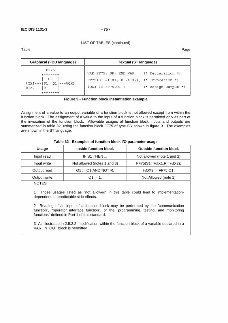
IEC DIS 1131-3 - 75 -
LIST OF TABLES (continued)
Table Page
Graphical (FBD language) Textual (ST language)
FF75 +------+ | SR | %IX1---|S1 Q1|---%QX3 %IX2---|R | +------+
VAR FF75: SR; END_VAR (* Declaration *)
FF75(S1:=%IX1, R:=%IX2); (* Invocation *)
%QX3 := FF75.Q1 ; (* Assign Output *)
Figure 9 - Function block instantiation example
Assignment of a value to an output variable of a function block is not allowed except from within the function block. The assignment of a value to the input of a function block is permitted only as part of the invocation of the function block. Allowable usages of function block inputs and outputs are summarized in table 32, using the function block FF75 of type SR shown in figure 9. The examples are shown in the ST language.
Table 32 - Examples of function block I/O parameter usage
Usage Inside function block Outside function block
Input read IF S1 THEN ... Not allowed (note 1 and 2)
Input write Not allowed (notes 1 and 3) FF75(S1:=%IX1,R:=%IX2);
Output read Q1 := Q1 AND NOT R; %QX3 := FF75.Q1;
Output write Q1 := 1; Not Allowed (note 1) NOTES
1 Those usages listed as "not allowed" in this table could lead to implementation-dependent, unpredictable side effects.
2 Reading of an input of a function block may be performed by the "communication function", "operator interface function", or the "programming, testing, and monitoring functions" defined in Part 1 of this standard.
3 As illustrated in 2.5.2.2, modification within the function block of a variable declared in a VAR_IN_OUT block is permitted.

- 76 - IEC DIS 1131-3
LIST OF TABLES (continued)
Table Page
2.5.2.2 Declaration
As illustrated in figure 10, a function block shall be declared textually or graphically in the same manner as defined for functions in 2.5.1.3, with the differences described below and summarized in table 33:
1) The delimiting keywords for declaration of function blocks shall be FUNCTION_BLOCK... END_FUNCTION_BLOCK.
2) A function block can have more than one output parameter, declared textually with the VAR_OUTPUT...END_VAR construct defined in 2.4.3, or graphically as illustrated in figure 10.
3) The RETAIN qualifier defined in 2.4.3 can be used for internal and output variables of a function block, as shown in features 1, 2, and 3 in table 33.
4) The values of variables which are passed to the function block via a VAR_IN_OUT or VAR_EXTERNAL construct can be modified from within the function block, as shown in feature 4 of table 33.
5) The output values of a function block instance whose name is passed into the function block via a VAR_INPUT, VAR_IN_OUT, or VAR_EXTERNAL construct can be accessed, but not modified, from within the function block, as shown in features 5, 6, and 7 of table 33.
6) A function block whose instance name is passed into the function block via a VAR_IN_OUT or VAR_EXTERNAL construction can be invoked from inside the function block, as shown in features 6 and 7 of table 33.
7) In textual declarations, the R_EDGE and F_EDGE qualifiers can be used to indicate an edge-detection function on Boolean inputs. This shall cause the implicit declaration of a function block of type R_TRIG or F_TRIG, respectively, as defined in 2.5.2.3.2, to perform the required edge detection. For an example of this construction, see features 8a and 8b of table 33 and the accompanying NOTE.
8) The construction illustrated in table 33, features 9a and 9b shall be used in graphical declarations for rising and falling edge detection. When the ISO/IEC 646 character set is used, the "greater than" (>) or "less than" (<) character shall be in line with the edge of the function block. When graphic or semigraphic representations are employed, the notation of IEC 617, Part 12 for dynamic inputs shall be used.
9) The variable initialization constructs defined in 2.4.3.2 can be used for the declaration of default values of function block inputs and initial values of their internal and output variables.
10) If the generic data types given in table 11 are used in the declaration of standard function block inputs and outputs, then the rules for inferring the actual types of the outputs of such function block types shall be part of the function block type definition.
As illustrated in figure 12, only variables or function block instance names can be passed into a function block via the VAR_IN_OUT construct, i.e., function or function block outputs cannot be passed via this construction. This is to prevent the inadvertent modifications of such outputs. However, "cascading" of VAR_IN_OUT constructions is permitted, as illustrated in figure 12c.
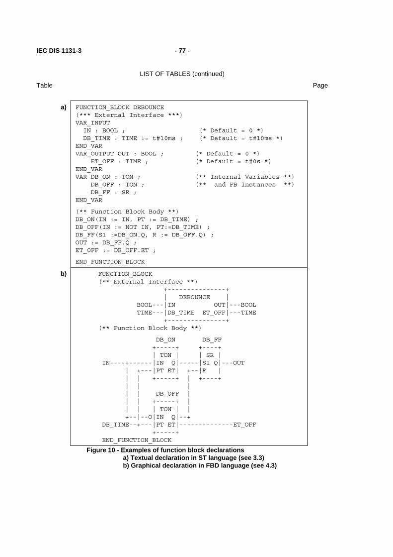
IEC DIS 1131-3 - 77 -
LIST OF TABLES (continued)
Table Page
a) FUNCTION_BLOCK DEBOUNCE
(*** External Interface ***) VAR_INPUT IN : BOOL ; (* Default = 0 *) DB_TIME : TIME := t#10ms ; (* Default = t#10ms *) END_VAR VAR_OUTPUT OUT : BOOL ; (* Default = 0 *) ET_OFF : TIME ; (* Default = t#0s *) END_VAR VAR DB_ON : TON ; (** Internal Variables **) DB_OFF : TON ; (** and FB Instances **) DB_FF : SR ; END_VAR
(** Function Block Body **) DB_ON(IN := IN, PT := DB_TIME) ; DB_OFF(IN := NOT IN, PT:=DB_TIME) ; DB_FF(S1 :=DB_ON.Q, R := DB_OFF.Q) ; OUT := DB_FF.Q ; ET_OFF := DB_OFF.ET ;
END_FUNCTION_BLOCK
b) FUNCTION_BLOCK (** External Interface **) +---------------+ | DEBOUNCE | BOOL---|IN OUT|---BOOL TIME---|DB_TIME ET_OFF|---TIME +---------------+ (** Function Block Body **)
DB_ON DB_FF +-----+ +----+ | TON | | SR | IN----+------|IN Q|-----|S1 Q|---OUT | +---|PT ET| +--|R | | | +-----+ | +----+ | | | | | DB_OFF | | | +-----+ | | | | TON | | +--|--O|IN Q|--+ DB_TIME--+---|PT ET|--------------ET_OFF +-----+ END_FUNCTION_BLOCK
Figure 10 - Examples of function block declarations a) Textual declaration in ST language (see 3.3) b) Graphical declaration in FBD language (see 4.3)

- 78 - IEC DIS 1131-3
LIST OF TABLES (continued)
Table Page
Table 33 - Function block declaration features
No. Description Example
1 RETAIN qualifier on internal variables VAR RETAIN X : REAL ; END_VAR
2 RETAIN qualifier on output variables VAR_OUTPUT RETAIN X : REAL ; END_VAR
3 RETAIN qualifier on internal function blocks VAR RETAIN TMR1: TON ; END_VAR
4a Input/output declaration (textual)
VAR_IN X: INT; END_VAR VAR_IN_OUT A: INT ; END_VAR A := A+X ;
4b Input/output declaration (graphical) See figure 12
5a Function block instance name as input (textual)
VAR_INPUT I_TMR: TON ; END_VAR EXPIRED := I_TMR.Q; (* Note 1 *)
5b Function block instance name as input (graphical)
See figure 11a
6a Function block instance name as input/output (textual)
VAR_IN_OUT IO_TMR: TOF ; END_VAR IO_TMR(IN:=A_VAR, PT:=T#10S); EXPIRED := IO_TMR.Q; (* Note 1 *)
6b Function block instance name as input/output (graphical)
See figure 11b
7a Function block instance name as external variable (textual)
VAR_EXTERNAL EX_TMR : TOF ;END_VAR EX_TMR(IN:=A_VAR, PT:=T#10S); EXPIRED := EX_TMR.Q; (* Note 1 *)
7b Function block instance name as external variable (graphical)
See figure 11c
8a 8b
Textual declaration of: rising edge inputs falling edge inputs
FUNCTION_BLOCK AND_EDGE (* Note 2 *) VAR_INPUT X : BOOL R_EDGE; Y : BOOL F_EDGE; END_VAR VAR_OUTPUT Z : BOOL ; END_VAR Z := X AND Y ; (* ST language example *) END_FUNCTION_BLOCK (*- see 3.3 *)
9a
9b
Graphical declaration of: rising edge inputs
falling edge inputs
FUNCTION_BLOCK (* Note 2 *) +-----------+ (* External interface *) | AND_EDGE | BOOL--->X Z|---BOOL | | BOOL---<Y | | | +-----------+ +---+ (* Function block body *) X---| & |---Z (* FBD language example *) Y---| | (* - see 4.3 *) +---+ END_FUNCTION_BLOCK
(continued on following page)

IEC DIS 1131-3 - 79 -
LIST OF TABLES (continued)
Table Page
Table 33 - Function block declaration features - continued NOTES
1 It is assumed in these examples that the variables EXPIRED and A_VAR have been declared of type BOOL.
2 The declaration of function block AND_EDGE in the above examples is equivalent to: FUNCTION_BLOCK AND_EDGE VAR INPUT X : BOOL; Y : BOOL; END_VAR VAR X_TRIG : R_TRIG ; Y_TRIG : F_TRIG ; END_VAR X_TRIG(CLK := X) ; Y_TRIG(CLK := Y) ; Z := X_TRIG.Q AND Y_TRIG.Q; END_FUNCTION_BLOCK
See 2.5.2.3.2 for the definition of the edge detection function blocks R_TRIG and F_TRIG.
FUNCTION_BLOCK +--------------+ (* External interface *) | INSIDE_A | TON---|I_TMR EXPIRED|---BOOL +--------------+ I_TMR (* Function Block body *) +-----+ | TON | |IN Q|---EXPIRED |PT ET| +-----+ END_FUNCTION_BLOCK
FUNCTION_BLOCK +--------------+ (* External interface *) | EXAMPLE_A | BOOL---|GO DONE|---BOOL +--------------+
E_TMR (* Function Block body *) +-----+ I_BLK | TON | +--------------+ GO---|IN Q| | INSIDE_A | t#100ms---|PT ET| E_TMR---|I_TMR EXPIRED|---DONE +-----+ +--------------+ END_FUNCTION_BLOCK
Figure 11a - Graphical use of a function block name as an input variable (table 33, feature 5b)

- 80 - IEC DIS 1131-3
LIST OF TABLES (continued)
Table Page
FUNCTION_BLOCK +--------------+ (* External interface *) | INSIDE_B | TON---|I_TMR----I_TMR|---TON BOOL--|TMR_GO EXPIRED|---BOOL +--------------+ I_TMR (* Function Block body *) +-----+ | TON | TMR_GO---|IN Q|---EXPIRED |PT ET| +-----+ END_FUNCTION_BLOCK
FUNCTION_BLOCK +--------------+ (* External interface *) | EXAMPLE_B | BOOL---|GO DONE|---BOOL +--------------+
E_TMR (* Function Block body *) +-----+ I_BLK | TON | +---------------+ |IN Q| | INSIDE_B | t#100ms---|PT ET| E_TMR---|I_TMR-----I_TMR| +-----+ GO------|TMR_GO EXPIRED|---DONE +---------------+ END_FUNCTION_BLOCK
Figure 11b - Graphical use of a function block name as an input/output variable (table 33, feature 6b)

IEC DIS 1131-3 - 81 -
LIST OF TABLES (continued)
Table Page
FUNCTION_BLOCK +--------------+ (* External interface *) | INSIDE_C | BOOL--|TMR_GO EXPIRED|---BOOL +--------------+
VAR_EXTERNAL X_TMR : TON ; END_VAR X_TMR (* Function Block body *) +-----+ | TON | TMR_GO---|IN Q|---EXPIRED |PT ET| +-----+ END_FUNCTION_BLOCK
PROGRAM +--------------+ (* External interface *) | EXAMPLE_C | BOOL---|GO DONE|---BOOL +--------------+ VAR_GLOBAL X_TMR : TON ; END_VAR
I_BLK (* Program body *) +---------------+ | INSIDE_C | GO------|TMR_GO EXPIRED|---DONE +---------------+ END_PROGRAM
NOTE - PROGRAM declaration is defined in 2.5.3.
Figure 11c - Graphical use of a function block name as an external variable (table 33, feature 7b)
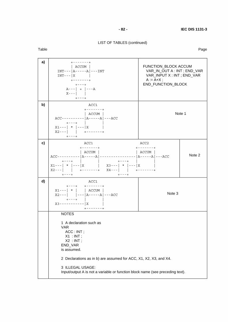
- 82 - IEC DIS 1131-3
LIST OF TABLES (continued)
Table Page
a) +-------+
| ACCUM | INT---|A-----A|---INT INT---|X | +-------+ +---+ A---| + |---A X---| | +---+
FUNCTION_BLOCK ACCUM VAR_IN_OUT A : INT ; END_VAR VAR_INPUT X : INT ; END_VAR A := A+X ; END_FUNCTION_BLOCK
b) ACC1 +-------+ | ACCUM | ACC----------|A-----A|---ACC +---+ | | X1---| * |---|X | X2---| | +-------+ +---+
Note 1
c) ACC1 ACC2 +-------+ +-------+ | ACCUM | | ACCUM | ACC----------|A-----A|----------------|A-----A|---ACC +---+ | | +---+ | | X1---| * |---|X | X3---| * |---|X | X2---| | +-------+ X4---| | +-------+ +---+ +---+
Note 2
d) ACC1 +---+ +-------+ X1---| * | | ACCUM | X2---| |---|A-----A|---ACC +---+ | | X3-----------|X | +-------+
Note 3
NOTES
1 A declaration such as VAR ACC : INT ; X1 : INT ; X2 : INT ; END_VAR is assumed.
2 Declarations as in b) are assumed for ACC, X1, X2, X3, and X4.
3 ILLEGAL USAGE: Input/output A is not a variable or function block name (see preceding text).
IEC DIS 1131-3 - 83 -
LIST OF TABLES (continued)
Table Page
Figure 12 - Examples of use of input/output variables a) Graphical and textual declarations b), c) Legal usage d) Illegal usage

- 84 - IEC DIS 1131-3
LIST OF TABLES (continued)
Table Page
2.5.2.3 Standard function blocks
Definitions of function blocks common to all programmable controller programming languages are given in this subclause.
Where graphical declarations of standard function blocks are shown in this subclause, equivalent textual declarations, as specified in 2.5.2.2, can also be written, as for example in table 35.
2.5.2.3.1 Bistable elements
The representation and function block bodies for standard bistable elements are shown in table 34. The notation for these elements is chosen to be as consistent as possible with symbols 12-09-01 and 12-09-02 of IEC 617-12.
Table 34 - Standard bistable function blocks
No. Graphical form Function block body
1 Bistable Function Block (set dominant) (notes 1 and 2)
+-----+ | SR | BOOL---|S1 Q1|---BOOL BOOL---|R | +-----+
+-----+ S1----------------| >=1 |---Q1 +---+ | | R------O| & |----| | Q1------| | | | +---+ +-----+
2 Bistable Function Block (reset dominant) (notes 1 and 2)
+-----+ | RS | BOOL---|S Q1|---BOOL BOOL---|R1 | +-----+
+---+ R1----------------O| & |---Q1 +-----+ | | S-------| >=1 |----| | Q1------| | | | +-----+ +---+
NOTES
1 The function block body is specified in the Function Block Diagram (FBD) language defined in 4.3.
2 The initial state of the output variable Q1 shall be the normal default value of zero for Boolean variables.

IEC DIS 1131-3 - 85 -
LIST OF TABLES (continued)
Table Page
2.5.2.3.2 Edge detection
The graphic representation of standard rising- and falling-edge detecting function blocks shall be as shown in table 35. The behaviors of these blocks shall be equivalent to the definitions given in this table. This behavior corresponds to the following rules:
1) The "Q" output of an R_TRIG function block shall stand at the Boolean "1" value from one execution of the function block to the next, following the "0" to "1" transition of the "CLK" input, and shall return to "0" at the next execution.
2) The "Q" output of an F_TRIG function block shall stand at the Boolean "1" value from one execution of the function block to the next, following the "1" to "0" transition of the "CLK" input, and shall return to "0" at the next execution.
Table 35 - Standard edge detection function blocks
No. Graphical form Definition (ST language - see 3.3)
1 Rising edge detector
+--------+ | R_TRIG | BOOL---|CLK Q|---BOOL +--------+
FUNCTION_BLOCK R_TRIG VAR_INPUT CLK: BOOL; END_VAR VAR_OUTPUT Q: BOOL; END_VAR VAR RETAIN M: BOOL; END_VAR Q := CLK AND NOT M; M := CLK; END_FUNCTION_BLOCK
2 Falling edge detector
+--------+ | F_TRIG | BOOL---|CLK Q|---BOOL +--------+
FUNCTION_BLOCK F_TRIG VAR_INPUT CLK: BOOL; END_VAR VAR_OUTPUT Q: BOOL; END_VAR VAR RETAIN M: BOOL; END_VAR Q := NOT CLK AND NOT M; M := NOT CLK; END_FUNCTION_BLOCK

- 86 - IEC DIS 1131-3
LIST OF TABLES (continued)
Table Page
2.5.2.3.3 Counters
The graphic representations of standard counter function blocks, with the types of the associated inputs and outputs, shall be as shown in table 36. The operation of these function blocks shall be as specified in the corresponding function block bodies.
Table 36 - Standard counter function blocks
No. Graphical form Function block body (ST language - see 3.3)
1 Up-counter
+-----+ | CTU | BOOL--->CU Q|---BOOL BOOL---|R | INT---|PV CV|---INT +-----+
IF R THEN CV := 0 ; ELSIF CU AND (CV < PVmax) THEN CV := CV+1; END_IF ; Q := (CV >= PV) ;
2 Down-counter
+-----+ | CTD | BOOL--->CD Q|---BOOL BOOL---|LD | INT---|PV CV|---INT +-----+
IF LD THEN CV := PV ; ELSIF CD AND (CV > PVmin) THEN CV := CV-1; END_IF ; Q := (CV <= 0) ;
3 Up-down counter
+------+ | CTUD | BOOL--->CU QU|---BOOL BOOL--->CD QD|---BOOL BOOL---|R | BOOL---|LD | INT---|PV CV|---INT +------+
IF R THEN CV := 0 ; ELSIF LD THEN CV := PV ; ELSE IF NOT (CU AND CD) THEN IF CU AND (CV < PVmax) THEN CV := CV+1; ELSIF CD AND (CV > PVmin) THEN CV := CV-1; END_IF; END_IF; END_IF ; QU := (CV >= PV) ; QD := (CV <= 0) ;
NOTE - The numerical values of the limit variables PVmin and PVmax are implementation-dependent.

IEC DIS 1131-3 - 87 -
LIST OF TABLES (continued)
Table Page
2.5.2.3.4 Timers
The graphic form for standard timer function blocks shall be as shown in table 37. The operation of these function blocks shall be as defined in the timing diagrams given in table 38. The RTC function block shown as feature No. 4 in table 37 shall set the output CDT to the input value PDT at the next evaluation of the function block following a transition from 0 to 1 of the IN input. The CDT output of the RTC function block shall be undefined when the value of IN is 0.
Table 37 - Standard timer function blocks
No. Description Graphical form
1 2a 2b 3a 3b
*** is: TP (Pulse)
TON (On-delay)
T---0 (On-delay)
TOF (Off-delay)
0---T (Off-delay)
+-------+ | *** | BOOL---|IN Q|---BOOL TIME---|PT ET|---TIME +-------+
4 Real-time clock
PDT = Preset date and time, loaded on rising edge of EN CDT = Current date and time, valid when EN=1 Q = copy of EN
+-------+ | RTC |
BOOL---|IN Q|---BOOL DT-----|PDT CDT|-----DT
+-------+
NOTES
1 In textual languages, features 2b and 3b shall not be used.
2 The effect of a change in the value of the PT input during the timing operation is an implementation-dependent parameter."
Table 38 - Standard timer function blocks - timing diagrams

- 88 - IEC DIS 1131-3
LIST OF TABLES (continued)
Table Page
Pulse (TP) timing
+--------+ ++ ++ +--------+ IN | | || || | | --+ +-----++-++---+ +--------- t0 t1 t2 t3 t4 t5
+----+ +----+ +----+ Q | | | | | | --+ +---------+ +--+ +------------- t0 t0+PT t2 t2+PT t4 t4+PT
PT +---+ + +---+ : / | /| / | ET : / | / | / | : / | / | / | : / | / | / | 0-+ +-----+ +--+ +--------- t0 t1 t2 t4 t5
(continued on following page)

IEC DIS 1131-3 - 89 -
LIST OF TABLES (continued)
Table Page
Table 38 - Standard timer Function Blocks - timing diagrams - continued
On-delay (TON) timing
+--------+ +---+ +--------+ IN | | | | | | --+ +--------+ +---+ +------------- t0 t1 t2 t3 t4 t5
+---+ +---+ Q | | | | -------+ +---------------------+ +------------- t0+PT t1 t4+PT t5
PT +---+ +---+ : / | + / | ET : / | /| / | : / | / | / | : / | / | / | 0-+ +--------+ +---+ +------------- t0 t1 t2 t3 t4 t5
Off-delay (TOF) timing
+--------+ +---+ +--------+ IN | | | | | | ---+ +--------+ +---+ +----------- t0 t1 t2 t3 t4 t5
+-------------+ +---------------------+ Q | | | | ---+ +---+ +------ t0 t1+PT t2 t5+PT
PT +---+ +------ : / | + / ET : / | /| / : / | / | / : / | / | / 0------------+ +---+ +--------+ t1 t3 t5
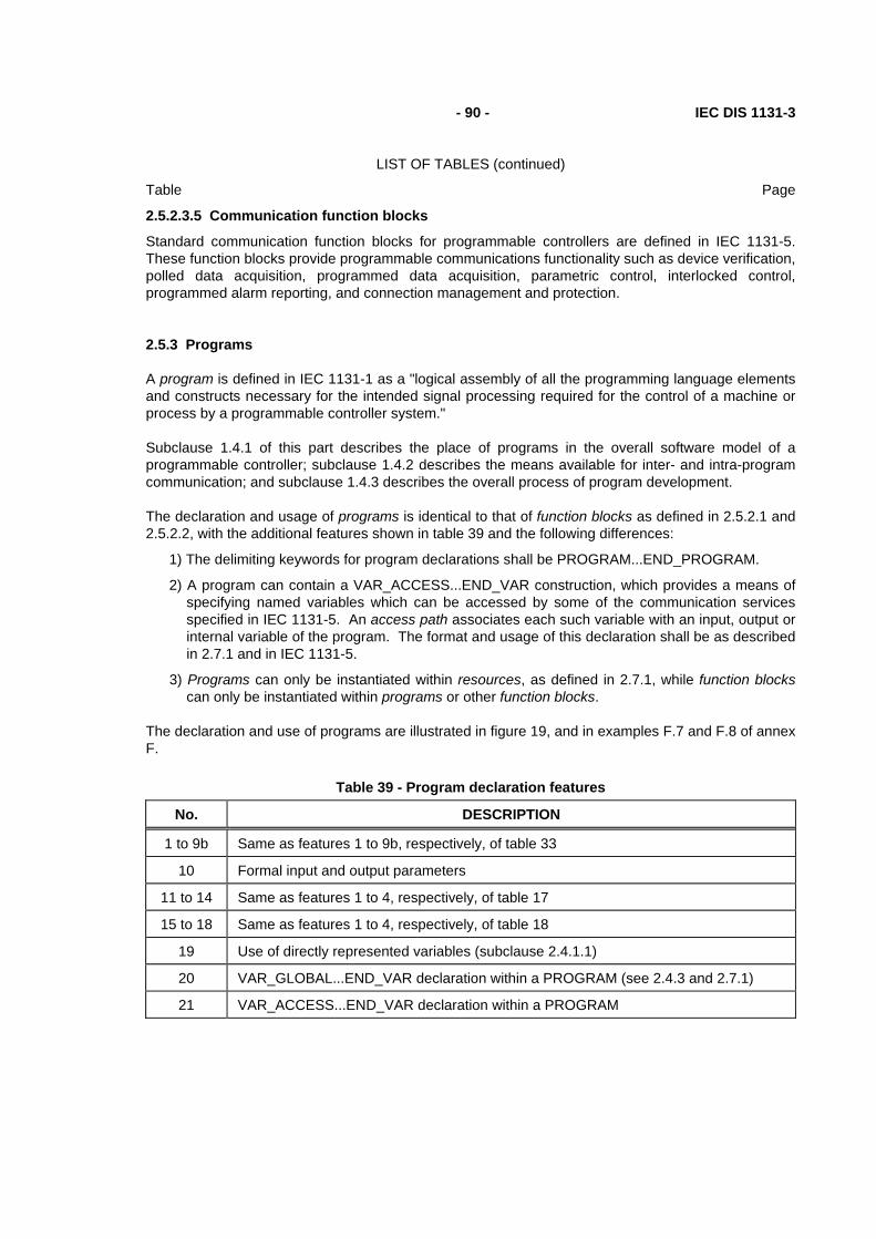
- 90 - IEC DIS 1131-3
LIST OF TABLES (continued)
Table Page
2.5.2.3.5 Communication function blocks
Standard communication function blocks for programmable controllers are defined in IEC 1131-5. These function blocks provide programmable communications functionality such as device verification, polled data acquisition, programmed data acquisition, parametric control, interlocked control, programmed alarm reporting, and connection management and protection.
2.5.3 Programs
A program is defined in IEC 1131-1 as a "logical assembly of all the programming language elements and constructs necessary for the intended signal processing required for the control of a machine or process by a programmable controller system."
Subclause 1.4.1 of this part describes the place of programs in the overall software model of a programmable controller; subclause 1.4.2 describes the means available for inter- and intra-program communication; and subclause 1.4.3 describes the overall process of program development.
The declaration and usage of programs is identical to that of function blocks as defined in 2.5.2.1 and 2.5.2.2, with the additional features shown in table 39 and the following differences:
1) The delimiting keywords for program declarations shall be PROGRAM...END_PROGRAM.
2) A program can contain a VAR_ACCESS...END_VAR construction, which provides a means of specifying named variables which can be accessed by some of the communication services specified in IEC 1131-5. An access path associates each such variable with an input, output or internal variable of the program. The format and usage of this declaration shall be as described in 2.7.1 and in IEC 1131-5.
3) Programs can only be instantiated within resources, as defined in 2.7.1, while function blocks can only be instantiated within programs or other function blocks.
The declaration and use of programs are illustrated in figure 19, and in examples F.7 and F.8 of annex F.
Table 39 - Program declaration features
No. DESCRIPTION
1 to 9b Same as features 1 to 9b, respectively, of table 33
10 Formal input and output parameters
11 to 14 Same as features 1 to 4, respectively, of table 17
15 to 18 Same as features 1 to 4, respectively, of table 18
19 Use of directly represented variables (subclause 2.4.1.1)
20 VAR_GLOBAL...END_VAR declaration within a PROGRAM (see 2.4.3 and 2.7.1)
21 VAR_ACCESS...END_VAR declaration within a PROGRAM

IEC DIS 1131-3 - 91 -
LIST OF TABLES (continued)
Table Page
2.6 Sequential Function Chart (SFC) elements
2.6.1 General
This subclause defines sequential function chart (SFC) elements for use in structuring the internal organization of a programmable controller program organization unit, written in one of the languages defined in this standard, for the purpose of performing sequential control functions. The definitions in this subclause are derived from IEC 848, with the changes necessary to convert the representations from a documentation standard to a set of execution control elements for a programmable controller program organization unit.
The SFC elements provide a means of partitioning a programmable controller program organization unit into a set of steps and transitions interconnected by directed links. Associated with each step is a set of actions, and with each transition is associated a transition condition.
Since SFC elements require storage of state information, the only program organization units which can be structured using these elements are function blocks and programs.
If any part of a program organization unit is partitioned into SFC elements, the entire program organization unit shall be so partitioned. If no SFC partitioning is given for a program organization unit, the entire program organization unit shall be considered to be a single action which executes under the control of the invoking entity.
2.6.2 Steps
A step represents a situation in which the behavior of a program organization unit with respect to its inputs and outputs follows a set of rules defined by the associated actions of the step. A step is either active or inactive. At any given moment, the state of the program organization unit is defined by the set of active steps and the values of its internal and output variables.
As shown in table 40, a step shall be represented graphically by a block containing a step name in the form of an identifier as defined in 2.1.2, or textually by a STEP...END_STEP construction. The directed link(s) into the step can be represented graphically by a vertical line attached to the top of the step. The directed link(s) out of the step can be represented by a vertical line attached to the bottom of the step. Alternatively, the directed links can be represented textually by the TRANSITION... END_TRANSITION construction defined in 2.6.3.
The step flag (active or inactive state of a step) can be represented by the logic value of a Boolean structure element ***.X, where *** is the step name, as shown in table 40. This Boolean variable has the value "1" when the corresponding step is active, and "0" when it is inactive. The state of this variable is available for graphical connection at the right side of the step as shown in table 40.
Similarly, the elapsed time, ***.T, since initiation of a step can be represented by a structure element of type TIME, as shown in table 40. When a step is deactivated, the value of the step elapsed time shall remain at the value it had when the step was deactivated. When a step is activated, the value of the step elapsed time shall be reset to t#0s.
The scope of step names, step flags, and step times shall be local to the program organization unit in which the steps appear.
The initial state of the program organization unit is represented by the initial values of its internal and output variables, and by its set of initial steps, i.e., the steps which are initially active. Each SFC network, or its textual equivalent, shall have exactly one initial step.

- 92 - IEC DIS 1131-3
LIST OF TABLES (continued)
Table Page
An initial step can be drawn graphically with double lines for the borders, and with the ISO 646 character set shall be drawn as shown in table 40.
For system initialization as defined in 2.4.2, the default initial elapsed time for steps is t#0s, and the default initial state is Boolean 0 for ordinary steps and Boolean 1 for initial steps. However, when an instance of a function block or a program is declared to be retentive (for instance, as in feature 3 of table 33), the states and (if supported) elapsed times of all steps contained in the program or function block shall be treated as retentive for system initialization as defined in 2.4.2.

IEC DIS 1131-3 - 93 -
LIST OF TABLES (continued)
Table Page
Table 40 - Step features
No. REPRESENTATION DESCRIPTION
1 | +-----+ | *** | +-----+ |
Step - Graphical form
with directed links "***" = step name
| +=======+ || *** || || || +=======+ |
Initial step - Graphical form with directed links "***" = Name of initial step
(note 2)
2 STEP *** : (* Step body *) END_STEP
Step - Textual form without directed links (see 2.6.3)
"***" = Step name
INITIAL_STEP *** : (* Step body *) END_STEP
Initial step - Textual form without directed links (see 2.6.3)
"***" = Name of initial step
3a
***.X
Step flag - General form "***" = Step name
***.X = Boolean 1 when *** is active, Boolean 0 otherwise
3b
| +-----+ | *** |---- +-----+ |
Step flag - Direct connection of Boolean variable ***.X to
right side of step "***"
4
***.T
Step elapsed time - General form "***" = Step name
***.T = A variable of type TIME
(See 2.6.2) NOTES
1. When feature 3a, 3b, or 4 is supported, it shall be an error if the user program attempts to modify the associated variable. For example, if S4 is a step name, then the following statements would be errors in the ST language defined in 3.3:
S4.X := 1 ; (* ERROR *) S4.T := t#100ms ; (* ERROR *)
2. The upper directed link is not required if the initial step has no predecessors.

- 94 - IEC DIS 1131-3
LIST OF TABLES (continued)
Table Page
2.6.3 Transitions
A transition represents the condition whereby control passes from one or more steps preceding the transition to one or more successor steps along the corresponding directed link. The transition shall be represented by a horizontal line across the vertical directed link.
The direction of evolution following the directed links shall be from the bottom of the predecessor step(s) to the top of the successor step(s).
Each transition shall have an associated transition condition which is the result of the evaluation of a single Boolean expression. A transition condition which is always true shall be represented by the symbol "1" or the keyword TRUE.
A transition condition can be associated with a transition by one of the following means, as shown in table 41:
1) By placing the appropriate Boolean expression in the ST language defined in 3.3 to the right of the vertical directed link.
2) By a ladder diagram network in the LD language defined in 4.2, whose output intersects the vertical directed link instead of a right rail.
3) By a network in the FBD language defined in 4.3, whose output intersects the vertical directed link.
4) By a LD or FBD network whose output intersects the vertical directed link via a connector as defined in 4.1.1.
5) By a TRANSITION...END_TRANSITION construct using the ST language. This shall consist of:
- The keywords TRANSITION FROM followed by the step name of the predecessor step (or, if there is more than one predecessor, by a parenthesized list of predecessor steps);
- The keyword TO followed by the step name of the successor step (or, if there is more than one successor, by a parenthesized list of successor steps);
- The assignment operator (:=), followed by a Boolean expression in the ST language, specifying the transition condition;
- The terminating keyword END_TRANSITION.
6) By a TRANSITION...END_TRANSITION construct using the IL language defined in 3.2. This shall consist of:
- The keywords TRANSITION FROM followed by the step name of the predecessor step (or, if there is more than one predecessor, by a parenthesized list of predecessor steps), followed by a colon (‘:’);
- The keyword TO followed by the step name of the successor step (or, if there is more than one successor, by a parenthesized list of successor steps);
- Beginning on a separate line, a list of instructions in the IL language, the result of whose evaluation determines the transition condition;
- The terminating keyword END_TRANSITION on a separate line.
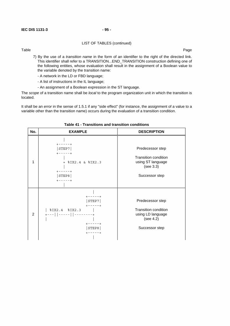
IEC DIS 1131-3 - 95 -
LIST OF TABLES (continued)
Table Page
7) By the use of a transition name in the form of an identifier to the right of the directed link. This identifier shall refer to a TRANSITION...END_TRANSITION construction defining one of the following entities, whose evaluation shall result in the assignment of a Boolean value to the variable denoted by the transition name: - A network in the LD or FBD language; - A list of instructions in the IL language; - An assignment of a Boolean expression in the ST language.
The scope of a transition name shall be local to the program organization unit in which the transition is located.
It shall be an error in the sense of 1.5.1 if any "side effect" (for instance, the assignment of a value to a variable other than the transition name) occurs during the evaluation of a transition condition.
Table 41 - Transitions and transition conditions
No. EXAMPLE DESCRIPTION
1
| +-----+ |STEP7| +-----+ | + %IX2.4 & %IX2.3 | +-----+ |STEP8| +-----+ |
Predecessor step
Transition condition using ST language
(see 3.3)
Successor step
2
| +-----+ |STEP7| +-----+ | %IX2.4 %IX2.3 | +---||-----||--------+ | | +-----+ |STEP8| +-----+ |
Predecessor step
Transition condition using LD language
(see 4.2)
Successor step
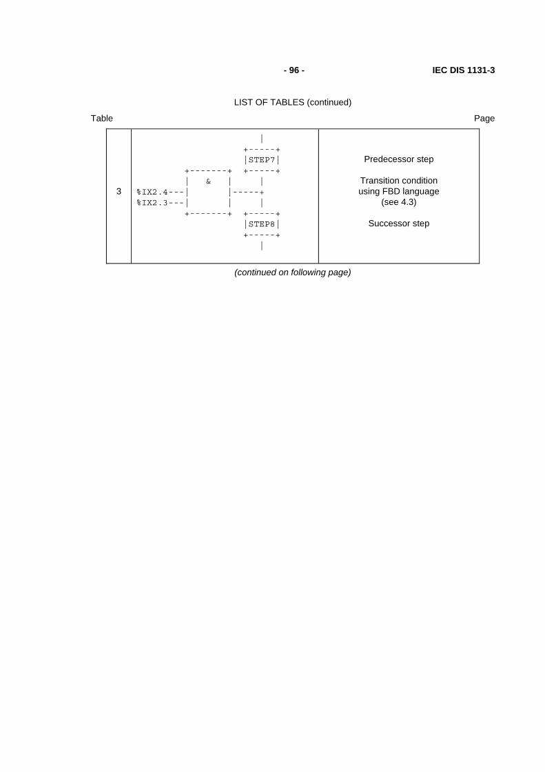
- 96 - IEC DIS 1131-3
LIST OF TABLES (continued)
Table Page
3
| +-----+ |STEP7| +-------+ +-----+ | & | | %IX2.4---| |-----+ %IX2.3---| | | +-------+ +-----+ |STEP8| +-----+ |
Predecessor step
Transition condition using FBD language
(see 4.3)
Successor step
(continued on following page)

IEC DIS 1131-3 - 97 -
LIST OF TABLES (continued)
Table Page
Table 41 - Transitions and transition conditions (continued)
No. Example Description
4
| +-----+ |STEP7| +-----+ | >TRANX>-------------+ | +-----+ |STEP8| +-----+ |
Use of connector:
Predecessor step
Transition connector
Successor step
4a
4b
| %IX2.4 %IX2.3 +---||-----||---->TRANX> | +-------+ | & | %IX2.4---| |-->TRANX> %IX2.3---| | +-------+
Transition condition: Using LD language
(see 4.2)
Using FBD language (see 4.3)
5
STEP STEP7: END_STEP TRANSITION FROM STEP7 TO STEP8 := %IX2.4 & %IX2.3 ; END_TRANSITION STEP STEP8: END_STEP
Textual equivalent of feature 1
using ST language (see 3.3)
6
STEP STEP7: END_STEP TRANSITION FROM STEP7 TO STEP 8: LD %IX2.4 AND %IX2.3 END_TRANSITION STEP STEP8: END_STEP
Textual equivalent of feature 1
using IL language (see 3.2)
(continued on following page)

- 98 - IEC DIS 1131-3
LIST OF TABLES (continued)
Table Page
Table 41 - Transitions and transition conditions (continued)
No. Example Description
7
| +-----+ |STEP7| +-----+
| + TRAN78
| +-----+ |STEP8| +-----+
|
Use of transition name:
Predecessor step
Transition name
Successor step
7a
TRANSITION TRAN78: | | | %IX2.4 %IX2.3 TRAN78 | +---||-----||------( )---+ | | END_TRANSITION
Transition condition using LD language
(see 4.2)
7b
TRANSITION TRAN78: +-------+ | & | %IX2.4---| |--TRAN78 %IX2.3---| | +-------+ END_TRANSITION
Transition condition using FBD language
(see 4.3)
7c
TRANSITION TRAN78: LD %IX2.4 AND %IX2.3 END_TRANSITION
Transition condition using IL language
(see 3.2)
7d
TRANSITION TRAN78 := %IX2.4 & %IX2.3 ; END_TRANSITION
Transition condition using ST language
(see 3.3) NOTES
1. If feature 1 of table 40 is supported, then one or more of features 1, 2, 3, 4, or 7 of this table shall be supported.
2. If feature 2 of table 40 is supported, then feature 5 or 6 of this table, or both, shall be supported.
IEC DIS 1131-3 - 99 -
LIST OF TABLES (continued)
Table Page
2.6.4 Actions
Zero or more actions shall be associated with each step. A step which has zero associated actions shall be considered as having a WAIT function, that is, waiting for a successor transition condition to become true.
An action can be a Boolean variable, a collection of instructions in the IL language defined in 3.2, a collection of statements in the ST language defined in 3.3, a collection of rungs in the LD language defined in 4.2, a collection of networks in the FBD language defined in 4.3, or a sequential function chart (SFC) organized as defined in this subclause (2.6).
Actions shall be declared via one or more of the mechanisms defined in 2.6.4.1, and shall be associated with steps via textual step bodies or graphical action blocks, as defined in 2.6.4.2. The details of action block representation are defined in 2.6.4.3. Control of actions shall be expressed by action qualifiers as defined in 2.6.4.4.
2.6.4.1 Declaration
A programmable controller implementation which supports SFC elements shall provide one or more of the mechanisms defined in table 42 for the declaration of actions. The scope of the declaration of an action shall be local to the program organization unit containing the declaration.
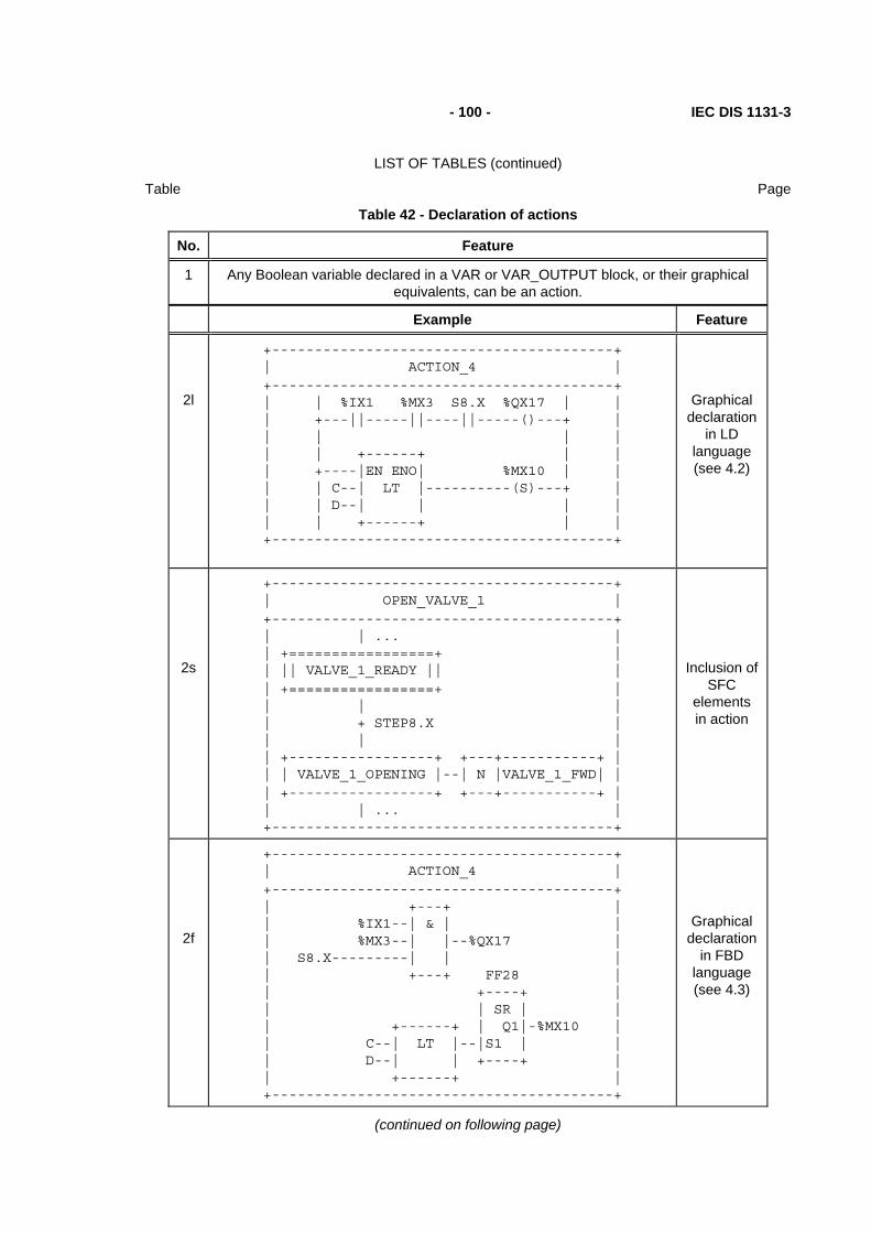
- 100 - IEC DIS 1131-3
LIST OF TABLES (continued)
Table Page
Table 42 - Declaration of actions
No. Feature
1 Any Boolean variable declared in a VAR or VAR_OUTPUT block, or their graphical equivalents, can be an action.
Example Feature
2l
+----------------------------------------+ | ACTION_4 | +----------------------------------------+ | | %IX1 %MX3 S8.X %QX17 | | | +---||-----||----||-----()---+ | | | | | | | +------+ | | | +----|EN ENO| %MX10 | | | | C--| LT |----------(S)---+ | | | D--| | | | | | +------+ | | +----------------------------------------+
Graphical declaration
in LD language (see 4.2)
2s
+----------------------------------------+ | OPEN_VALVE_1 | +----------------------------------------+ | | ... | | +=================+ | | || VALVE_1_READY || | | +=================+ | | | | | + STEP8.X | | | | | +-----------------+ +---+-----------+ | | | VALVE_1_OPENING |--| N |VALVE_1_FWD| | | +-----------------+ +---+-----------+ | | | ... | +----------------------------------------+
Inclusion ofSFC
elements in action
2f
+----------------------------------------+ | ACTION_4 | +----------------------------------------+ | +---+ | | %IX1--| & | | | %MX3--| |--%QX17 | | S8.X---------| | | | +---+ FF28 | | +----+ | | | SR | | | +------+ | Q1|-%MX10 | | C--| LT |--|S1 | | | D--| | +----+ | | +------+ | +----------------------------------------+
Graphical declaration
in FBD language (see 4.3)
(continued on following page)

IEC DIS 1131-3 - 101 -
LIST OF TABLES (continued)
Table Page
Table 42 - Declaration of actions (continued)
No. Example Feature
3s
ACTION ACTION_4: %QX17 := %IX1 & %MX3 & S8.X ; FF28(S1 := (C<D)); %MX10 := FF28.Q; END_ACTION
Textual declaration
in ST language (see 3.3)
3i
ACTION ACTION_4: LD S8.X AND %IX1 AND %MX3 ST %QX17 LD C LT D S1 FF28 LD FF28.Q ST %MX10 END_ACTION
Textual declaration
in IL language (see 3.2)
NOTES
1 - The step flag S8.X is used in these examples to obtain the desired result that, when S8 is deactivated, %QX17 := 0.
2 - If feature 1 of table 40 is supported, then one or more of the features in this table, or feature 4 of table 43, shall be supported.
3 - If feature 2 of table 40 is supported, then one or more of features 1,3s, or 3i of this table shall be supported.

- 102 - IEC DIS 1131-3
LIST OF TABLES (continued)
Table Page
2.6.4.2 Association with steps
A programmable controller implementation which supports SFC elements shall provide one or more of the mechanisms defined in table 43 for the association of actions with steps.
Table 43 - Step/action association
No. Example Feature
1
| +----+ +-----+----------+---+ | S8 |--| L | ACTION_1 |DN1| +----+ |t#10s| | | | +-----+----------+---+ + DN1 |
Action block (see 2.6.4.3)
2
| +----+ +-----+---------------------+---+ | S8 |--| L | ACTION_1 |DN1| +----+ |t#10s| | | | +-----+---------------------+---+ +DN1 | P | ACTION_2 | | | +-----+---------------------+---+ | | N | ACTION_3 | | | +-----+---------------------+---+
Concatenatedaction blocks
3
STEP S8: ACTION_1(L,t#10s,DN1) ; ACTION_2(P) ; ACTION_3(N) ; END_STEP
Textual
step body
4
+-----+----------------------+---+ ----| N | ACTION_4 | |--- +-----+----------------------+---+ | %QX17 := %IX1 & %MX3 & S8.X ; | | FF28 (S1 := (C<D)); | | %MX10 := FF28.Q; | +--------------------------------+
Action block "d" Field
(see 2.6.4.3)
NOTE - When feature 4 is used, the corresponding action name cannot be used in any other action block.

IEC DIS 1131-3 - 103 -
LIST OF TABLES (continued)
Table Page
2.6.4.3 Action blocks
As shown in table 44, an action block is a graphical element for the combination of a Boolean variable with one of the action qualifiers specified in subclause 2.6.4.4 to produce an enabling condition, according to the rukes given in subclause 2.6.4.5, par an associated action.
The action block provides a means of optionally specifying Boolean "indicator" variables, indicated by the "c" field in table 44, which can be set by the specified action to indicate its completion, timeout, error conditions, etc. If the "c" field is not present, and the "b" field specifies that the action shall be a Boolean variable, then this variable shall be interpreted as the "c" variable when required.
When action blocks are concatenated graphically as illustrated in table 43, such concatenations can have multiple indicator variables, but shall have only a single common Boolean input variable, which shall act simultaneously upon all the concatenated blocks.
As well as being associated with a step, an action block can be used as a graphical element in the LD or FBD languages specified in clause 4. In this case, signal or power flow through an action block shall follow the rules specified in 4.1.1.
Table 44 - Action block features
No. Feature Graphical form
1 2 3
4 5 6 7
"a" : Qualifier as per 2.6.4.4 "b" : Action name "c" : Boolean "indicator" variables "d" : Action using:
IL language (3.2) ST language (3.3) LD language (4.2) FBD language (4.3)
+-----+--------------+-----+
---| "a" | "b" | "c" |--- +-----+--------------+-----+ | "d" | | | +--------------------------+
No. Feature/Example
8 Use of action blocks in ladder diagrams (see 4.2):
| S8.X %IX7.5 +---+------+---+ OK1 | +--| |----| |----| N | ACT1 |DN1|--( )--+ | +---+------+---+ |
9 Use of action blocks in function block diagrams (see 4.3):
+---+ +---+------+-----+ S8.X---| & |-----| N | ACT1 | DN1 |---OK1 %IX7.5---| | +---+------+-----+ +---+
NOTES
1. Field "a" can be omitted when the qualifier is "N".
2. Field "c" can be omitted when no feedback variable is used.

- 104 - IEC DIS 1131-3
LIST OF TABLES (continued)
Table Page
2.6.4.4 Action qualifiers
Associated with each step/action association defined in 2.6.4.2, or each occurrence of an action block as defined in 2.6.4.3, shall be an action qualifier. The value of this qualifier shall be one of the values listed in table 45. In addition, the qualifiers L, D, SD, DS, and SL shall have an associated duration of type TIME.
NOTE - IEC 848 gives informal definitions and examples of the use of these qualifiers. This standard formalizes these definitions, redefining the "S" qualifier and introducing the "R" qualifier. The control of actions using these qualifiers is defined in the following subclause, and additional examples of their use are given in annex F.
Table 45 - Action qualifiers
No. Qualifier Explanation
1 None Non-stored (null qualifier)
2 N Non-stored
3 R overriding Reset
4 S Set (Stored)
5 L time Limited
6 D time Delayed
7 P Pulse
8 SD Stored and time Delayed
9 DS Delayed and Stored
10 SL Stored and time Limited
2.6.4.5 Action control
The control of actions shall be functionally equivalent to the application of the following rules:
1) Associated with each action shall be the functional equivalent of an instance of the ACTION_CONTROL function block defined in figures 14 and 15. If the action is declared as a Boolean variable, as defined in 2.6.4.1, the "Q" output of this block shall be the state of this Boolean variable. If the action is declared as a collection of statements or networks, as defined in 2.6.4.1, then this collection shall be executed upon each invocation of the program organisation unit (POU) in which the action is contained while the "Q" output of the ACTION_CONTROL function block stands at Boolean 1. The statements or networks shall be executed one final time after the falling edge of "Q".
2) A Boolean input to the ACTION_CONTROL block for an action shall be said to have an association with a step as defined in 2.6.4.2, or with an action block as defined in 2.6.4.3, if the corresponding qualifier is equivalent to the input name (N, R, S, L, D, P, SD, DS, or SL). The association shall be said to be active if the associated step is active, or if the associated action block's input has the value Boolean 1. The active associations of an action are equivalent to the set of active associations of all inputs to its ACTION_CONTROL function block.
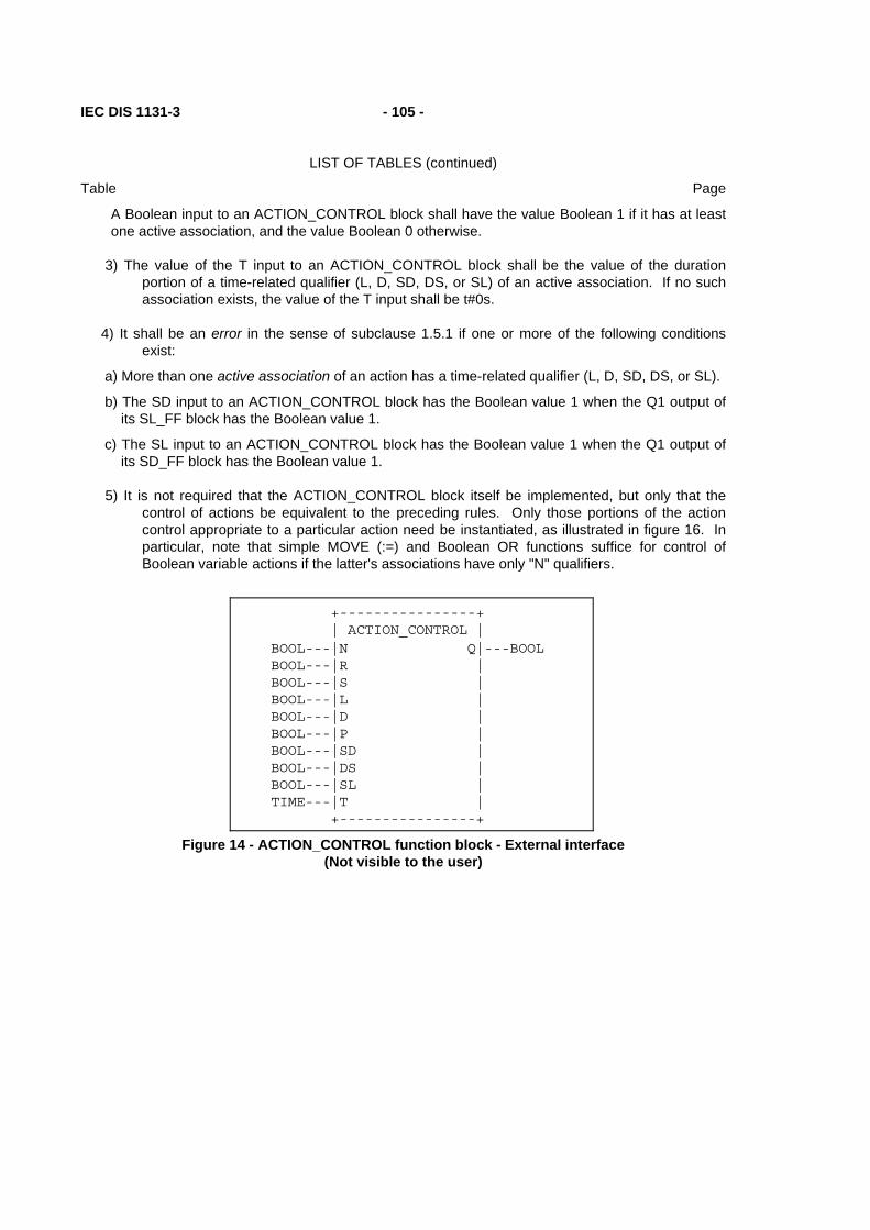
IEC DIS 1131-3 - 105 -
LIST OF TABLES (continued)
Table Page
A Boolean input to an ACTION_CONTROL block shall have the value Boolean 1 if it has at least one active association, and the value Boolean 0 otherwise.
3) The value of the T input to an ACTION_CONTROL block shall be the value of the duration portion of a time-related qualifier (L, D, SD, DS, or SL) of an active association. If no such association exists, the value of the T input shall be t#0s.
4) It shall be an error in the sense of subclause 1.5.1 if one or more of the following conditions exist:
a) More than one active association of an action has a time-related qualifier (L, D, SD, DS, or SL).
b) The SD input to an ACTION_CONTROL block has the Boolean value 1 when the Q1 output of its SL_FF block has the Boolean value 1.
c) The SL input to an ACTION_CONTROL block has the Boolean value 1 when the Q1 output of its SD_FF block has the Boolean value 1.
5) It is not required that the ACTION_CONTROL block itself be implemented, but only that the control of actions be equivalent to the preceding rules. Only those portions of the action control appropriate to a particular action need be instantiated, as illustrated in figure 16. In particular, note that simple MOVE (:=) and Boolean OR functions suffice for control of Boolean variable actions if the latter's associations have only "N" qualifiers.
+----------------+ | ACTION_CONTROL | BOOL---|N Q|---BOOL BOOL---|R | BOOL---|S | BOOL---|L | BOOL---|D | BOOL---|P | BOOL---|SD | BOOL---|DS | BOOL---|SL | TIME---|T | +----------------+
Figure 14 - ACTION_CONTROL function block - External interface (Not visible to the user)

- 106 - IEC DIS 1131-3
LIST OF TABLES (continued)
Table Page
+---+ +-----------------------------------------------------O| & |---Q | +-----+ | | N--|---------------------------------------------| >=1 |--| | | S_FF | | +---+ R--+ +----+ | | | | RS | | | S--|----------------------|S Q1|-----------------| | +----------------------|R1 | | | | +----+ +---+ | | L--|---------+--------------------| & |----------| | | | L_TMR +--O| | | | | | +-----+ | +---+ | | | | | TON | | | | | +------|IN Q|---+ D_TMR | | | +-------------|PT | +-----+ | | | | +-----+ | TON | | | D--|--|-----------------------------|IN Q|------| | | +-----------------------------|PT | | | | | P_TRIG +-----+ | | | | +--------+ | | | | | R_TRIG | | | P--|--|------------|CLK Q|--------------------| | | | SD_FF +--------+ SD_TMR | | | | +----+ +-----+ | | | | | RS | | TON | | | SD-|--|---|S Q1|----------------|IN Q|----------| | +--|---|R1 | +------------|PT | | | | | +----+ | DS_TMR +-----+ DS_FF | | | +------------+ +-----+ +----+ | | | | | TON | | RS | | | DS-|--|----------------|IN Q|----------|S Q1|---| | | +----------------|PT | +---|R1 | | | | | +-----+ | +----+ | | +--|-----------------------------+ | | | | SL_FF | | | | +----+ | | | | | RS | +---+ | | SL-|--|--------|S Q1|--+------------------| & |--| | +--|--------|R1 | | SL_TMR +--O| | +-----+ | +----+ | +-----+ | +---+ | | | TON | | | +----|IN Q|---+ T-----+---------------------|PT | +-----+
Figure 15 - ACTION_CONTROL function block body (not visible to the user)

IEC DIS 1131-3 - 107 -
LIST OF TABLES (continued)
Table Page
| +-----+ +---+------------+----------------+ | S22 |---| N | HV_BREAKER | HV_BRKR_CLOSED | +-----+ +---+------------+----------------+ | | S | START_INDICATOR | | +---+-----------------------------+ + HV_BRKR_CLOSED | +-----+ +----+---------------+ | S23 |---| SL | RUNUP_MONITOR | +-----+ |t#1m| | | +----+---------------+ | | D | START_WAIT | | |t#1s| | | +----+---------------+ + START_WAIT | +-----+ +-----+-----------------+------------------+ | S24 |---| N | ADVANCE_STARTER | STARTER_ADVANCED | +-----+ +-----+-----------------+------------------+ | | L | START_MONITOR | | |t#30s| | | +-----+------------------------------------+ + STARTER_ADVANCED | +-----+ +-----+-----------------+-------------------+ | S26 |---| N | RETRACT_STARTER | STARTER_RETRACTED | +-----+ +-----+-----------------+-------------------+ | | + STARTER_RETRACTED | +-----+ +-----+-----------------+ | S27 |---| R | START_INDICATOR | +-----+ +-----+-----------------+ | | R | RUNUP_MONITOR | | +-----+-----------------+
NOTE - The complete SFC network and its associated declarations are not shown in this example.
Figure 16a - Action control example - SFC representation
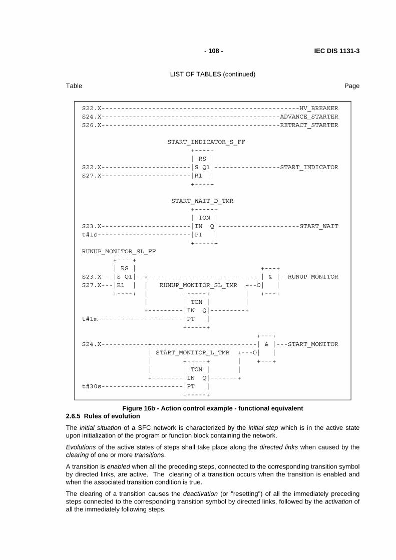
- 108 - IEC DIS 1131-3
LIST OF TABLES (continued)
Table Page
S22.X---------------------------------------------------HV_BREAKER S24.X----------------------------------------------ADVANCE_STARTER S26.X----------------------------------------------RETRACT_STARTER START_INDICATOR_S_FF +----+ | RS | S22.X-----------------------|S Q1|-----------------START_INDICATOR S27.X-----------------------|R1 | +----+ START_WAIT_D_TMR +-----+ | TON | S23.X-----------------------|IN Q|---------------------START_WAIT t#1s------------------------|PT | +-----+ RUNUP_MONITOR_SL_FF +----+ | RS | +---+ S23.X---|S Q1|--+-----------------------------| & |--RUNUP_MONITOR S27.X---|R1 | | RUNUP_MONITOR_SL_TMR +--O| | +----+ | +-----+ | +---+ | | TON | | +---------|IN Q|---------+ t#1m----------------------|PT | +-----+ +---+ S24.X------------+---------------------------| & |---START_MONITOR | START_MONITOR_L_TMR +---O| | | +-----+ | +---+ | | TON | | +--------|IN Q|-------+ t#30s---------------------|PT | +-----+
Figure 16b - Action control example - functional equivalent 2.6.5 Rules of evolution
The initial situation of a SFC network is characterized by the initial step which is in the active state upon initialization of the program or function block containing the network.
Evolutions of the active states of steps shall take place along the directed links when caused by the clearing of one or more transitions.
A transition is enabled when all the preceding steps, connected to the corresponding transition symbol by directed links, are active. The clearing of a transition occurs when the transition is enabled and when the associated transition condition is true.
The clearing of a transition causes the deactivation (or "resetting") of all the immediately preceding steps connected to the corresponding transition symbol by directed links, followed by the activation of all the immediately following steps.
IEC DIS 1131-3 - 109 -
LIST OF TABLES (continued)
Table Page
The alternation Step/Transition and Transition/Step shall always be maintained in SFC element connections, that is:
- Two steps shall never be directly linked; they shall always be separated by a transition.
- Two transitions shall never be directly linked; they shall always be separated by a step.
When the clearing of a transition leads to the activation of several steps at the same time, the sequences to which these steps belong are called simultaneous sequences. After their simultaneous activation, the evolution of each of these sequences becomes independent. In order to emphasize the special nature of such constructs, the divergence and convergence of simultaneous sequences shall be indicated by a double horizontal line.
Table 46 defines the syntax and semantics of the allowed combinations of steps and transitions.
The clearing time of a transition may theoretically be considered as short as one may wish, but it can never be zero. In practice, the clearing time will be imposed by the programmable controller implementation. For the same reason, the duration of a step activity can never be considered to be zero.
Several transitions which can be cleared simultaneously shall be cleared simultaneously, within the timing constraints of the particular programmable controller implementation and the priority constraints defined in table 46.
Testing of the successor transition condition(s) of an active step shall not be performed until the effects of the step activation have propagated throughout the program organization unit in which the step is declared.
Figure 17 illustrates the application of these rules. In this figure, the active state of a step is indicated by the presence of an asterisk (*) in the corresponding block. This notation is used for illustration only, and is not a required language feature.
The application of the rules given in this subclause cannot prevent the formulation of "unsafe" SFCs, such as the one shown in figure 18a, which may exhibit uncontrolled proliferation of tokens. Likewise, the application of these rules cannot prevent the formulation of "unreachable" SFCs, such as the one shown in figure 18b, which may exhibit "locked up" behavior. The programmable controller system shall treat the existence of such conditions as errors as defined in 1.5.1.

- 110 - IEC DIS 1131-3
LIST OF TABLES (continued)
Table Page
Table 46 - Sequence evolution
No. Example Rule
1
| +----+ | S3 | +----+
| + c
| +----+ | S4 | +----+
|
Single sequence: The alternation step-transition is repeated
in series.
Example: An evolution from step S3 to step S4 shall take place if and only if step S3 is in the active state and the transition condition c
is true.
2a
| +----+ | S5 | +----+ | +-----*----+--... | | + e + f | | +----+ +----+ | S6 | | S8 | +----+ +----+ | |
Divergence of sequence selection: A selection between several sequences
is represented by as many transition symbols, under the horizontal line, as there are different possible evolutions.
The asterisk denotes left-to-right priority of transition evaluations.
Example: An evolution shall take place from S5 to S6 only if S5 is active and the transition condition "e" is true, or from S5 to S8
only if S5 is active and "f" is true and "e" is false.
2b
| +----+ | S5 | +----+
| +-----*-----+--...
|2 |1 + e + f | |
+----+ +----+ | S6 | | S8 | +----+ +----+
| |
Divergence of sequence selection: The asterisk, followed by numbered branches, indicates a user-defined
priority of transition evaluation, with the lowest-numbered branch having the
highest priority.
Example: An evolution shall take place from S5 to S8 only if S5 is active and the transition
condition "f" is true, or from S5 to S6 only if S5 is active, and "e" is true, and
"f" is false.

IEC DIS 1131-3 - 111 -
LIST OF TABLES (continued)
Table Page
2c | +----+ | S5 | +----+ | +------+----+--... | | +e +NOT e & f | | +----+ +----+ | S6 | | S8 | +----+ +----+ | |
Divergence of sequence selection: The connection of the branch indicates
that the user must assure that transitionconditions are mutually
exclusive, asspecified by IEC 848.
Example: S6 only if S5 is active and the transition condition "e" is true, or from S5 to S8 only if S5 is active and "e" is false and
"f" is true.

- 112 - IEC DIS 1131-3
LIST OF TABLES (continued)
Table Page
Table 46 - Sequence evolution (continued)
3
| | +----+ +----+ | S7 | | S9 | +----+ +----+
| | + h + j | |
+-----+-----+--... |
+----+ |S10 | +----+
|
Convergence of sequence selection: The end of a sequence selection is represented by as many transition
symbols, above the horizontal line, as there are selection paths to be ended.
Example: An evolution shall take place
from S7 to S10 only if S7 is active and the transition condition "h" is true, or
from S9 to S10 only if S9 is active and "j" is true.
4
| +----+ |S11 | +----+
| + b
| ==+=====+=====+==...
| | +----+ +----+ | S12| | S14| +----+ +----+
| |
Simultaneous sequences - divergence:
Only one common transition symbol shall be possible, immediately above
the double horizontal line of synchronization.
Example: An evolution shall take place from S11 to S12, S14,... only if S11 is active and
the transition condition "b" associated to the common transition is true. After the
simultaneous activation of S12, S14, etc., the evolution of each sequence
proceeds independently.
| | +----+ +----+ | S13| | S15| +----+ +----+
| | ==+=====+=====+==...
| + d
| +----+ |S16 | +----+
|
Simultaneous sequences - convergence:
Only one common transition symbol shall be possible, immediately under the
double horizontal line of synchronization.
Example: An evolution shall take place from S13, S15,... to S16 only if all steps above and connected to the double horizontal line are active and the transition condition
"d" associated to the common transition is true.
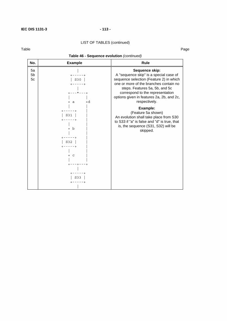
IEC DIS 1131-3 - 113 -
LIST OF TABLES (continued)
Table Page
Table 46 - Sequence evolution (continued)
No. Example Rule
5a 5b 5c
| +-----+ | S30 | +-----+
| +---*---+ | | + a +d | | +-----+ | | S31 | | +-----+ | | | + b | | | +-----+ | | S32 | | +-----+ | | | + c | | | +---+---+
| +-----+ | S33 | +-----+
|
Sequence skip: A "sequence skip" is a special case of
sequence selection (Feature 2) in which one or more of the branches contain no
steps. Features 5a, 5b, and 5c correspond to the representation
options given in features 2a, 2b, and 2c, respectively.
Example: (Feature 5a shown)
An evolution shall take place from S30 to S33 if "a" is false and "d" is true, that
is, the sequence (S31, S32) will be skipped.

- 114 - IEC DIS 1131-3
LIST OF TABLES (continued)
Table Page
6a 6b 6c
| +-----+ | S30 | +-----+
| + a
| +---------+ | | +-----+ | | S31 | | +-----+ | | | + b | | | +-----+ | | S32 | | +-----+ | | | *-----+ | | | | + c + d | | | | +-----+ +---+
| S33 | +-----+
|
Sequence loop: A "sequence loop" is a special case of
sequence selection (Feature 2) in which one or more of the branches returns to a preceding step. Features 6a, 6b, and
6c correspond to the representation options given in features 2a, 2b, and 2c,
respectively.
Example: (Feature 6a shown)
An evolution shall take place from S32 to S31 if "c" is false and "d" is true, that
is, the sequence (S31, S32) will be repeated.
Table 46 - Sequence evolution (concluded)
No. Example Rule

IEC DIS 1131-3 - 115 -
LIST OF TABLES (continued)
Table Page
7
| +-----+ | S30 | +-----+
| + a
| +----<----+ | | +-----+ | | S31 | | +-----+ | | | + b | | | +-----+ | | S32 | | +-----+ | | | *-----+ | | | | + c + d | | | | +-----+ +->-+
| S33 | +-----+
|
Directional arrows: When necessary for clarity, the "less than" (<) character of the ISO 646
character set can be used to indicate right-to-left control flow, and the "greater than" (>) character to represent left-to-right control flow. When this feature is
used, the corresponding character shall be located between two "-" characters, that is, in the character sequence "-<-" or "->-" as shown in the accompanying
example.

- 116 - IEC DIS 1131-3
LIST OF TABLES (continued)
Table Page
a) Transition not enabled ( X = Don’t care)
| | | | +------+ +-----+ +------+ +------+ |STEP10| |STEP9| |STEP13| |STEP22| | | | | | * | | * | +------+ +-----+ +------+ +------+ | | | | + X ====+========+=========+==== | | +------+ + X |STEP11| | | | ====+====+===+==== +------+ | | | +------+ +------+ |STEP15| |STEP16| | | | | +------+ +------+ | |
b) Transition enabled but not cleared ( X = 0 )
| | | | +------+ +-----+ +------+ +------+ |STEP10| |STEP9| |STEP13| |STEP22| | * | | * | | * | | * | +------+ +-----+ +------+ +------+ | | | | + X ===+========+=========+==== | | +------+ + X |STEP11| | | | ====+====+====+==== +------+ | | | +------+ +------+ |STEP15| |STEP16| | | | | +------+ +------+ | |
c) Transition cleared ( X = 1 )
| | | | +------+ +-----+ +------+ +------+ |STEP10| |STEP9| |STEP13| |STEP22| | | | | | | | | +------+ +-----+ +------+ +------+ | | | | + X ====+========+=========+==== | | +------+ + X |STEP11| | | * | ====+====+===+==== +------+ | | | +------+ +------+ |STEP15| |STEP16| | * | | * | +------+ +------+ | |

IEC DIS 1131-3 - 117 -
LIST OF TABLES (continued)
Table Page
NOTE - In this figure, the active state of a step is indicated by the presence of an asterisk (*) in the corresponding block. This notation is used for illustration only, and is not a required language feature.
Figure 17 - SFC evolution rules
+----------------------+ | | | +=====+ | || A || | +=====+ | | | + t1 | | | ======+==========+============+======= | | | | +-----+ +-----+ | | B | | C | | +-----+ +-----+ | | | | | *--------+ | | | | | | + t2 + t3 | | | | | | +---+ +---+ | | | D | | E | | | +---+ +---+ | | | | | ===+==========+============+=== | | | | | + t4 + t5 | | | | +---+ +---+ | | F | | G | | +---+ +---+ | | | | + t6 + t7 | | | +----------------------+---------------------+
Figure 18a - SFC errors: an "unsafe" SFC (see 2.6.5)

- 118 - IEC DIS 1131-3
LIST OF TABLES (continued)
Table Page
+----------------------+ | | | +=====+ | || A || | +=====+ | | | + t1 | | | ======+==========+============+======= | | | | +-----+ +-----+ | | B | | C | | +-----+ +-----+ | | | | | *--------+ | | | | | | + t2 + t3 | | | | | | +---+ +---+ | | | D | | E | | | +---+ +---+ | | | | | ===+==========+============+=== | | | | | + t4 + t5 | | | | +---+ +---+ | | F | | G | | +---+ +---+ | | | | ====+==========+==========+=== | | | + t6 | | +---------------------------------+
Figure 18b - SFC errors: an "unreachable" SFC (see 2.6.5)

IEC DIS 1131-3 - 119 -
LIST OF TABLES (continued)
Table Page
2.6.6 Compatibility of SFC elements
SFCs can be represented graphically or textually, utilizing the elements defined above. Table 47 summarizes for convenience those elements which are mutually compatible for graphical and textual representation, respectively.
Table 47 - Compatible SFC features
Table Graphical representation Textual representation
40 1, 3a, 3b, 4 2, 3a, 4
41 1,2,3,4,4a,4b,7,7a,7b 5, 6, 7c, 7d
42 1, 2l, 2s, 2f 3s,3i
43 1, 2, 4 3
44 1 to 9 --
45 1 to 10 1 to 10 (textual equivalent)
46 1 to 7 1 to 6
57 All --
2.6.7 Compliance requirements
In order to claim compliance with the requirements of 2.6, the elements shown in table 48 shall be supported and the compatibility requirements defined in 2.6.6 shall be observed.
Table 48 - SFC minimal compliance requirements
Table Graphical representation Textual representation
40 1 2
41 1 or 2 or 3 or (4 and (4a or 4b)) or (7 and (7a or 7b or 7c or 7d))
5 or 6
42 1 or 2l or 2f 3s or 3i
43 1 or 2 or 4 3
45 1 or 2 1 or 2
46 1 and (2a or 2b or 2c) and 3 and 4 Same (textual equivalent)
57 (1 or 2) and (3 or 4) and (5 or 6) and (7 or 8) and (9 or 10) and (11 or 12)
Not required

- 120 - IEC DIS 1131-3
LIST OF TABLES (continued)
Table Page
2.7 Configuration elements
As described in 1.4.1, a configuration consists of resources, tasks (which are defined within resources), global variables, and access paths. Each of these elements is defined in detail in this subclause.
A graphic example of a simple configuration is shown in figure 19a. Skeleton declarations for the corresponding function blocks and programs are given in figure 19b. This figure serves as a reference point for the examples of configuration elements given in the remainder of this subclause such as in figure 20.
CONFIGURATION CELL_1RESOURCE STATION_1 RESOURCE STATION_2
GLOBAL AND DIRECTLY REPRESENTED VARIABLES
ACCESS PATHS
w
BAKER ABLE CHARLIE DOG GAMMA ALPHA BETA
Communication function (See IEC 1131-5)
PROGRAM F PROGRAM G
A B
P1 P2
x1
y1
FB1 FB2
z1
x2
out1
y2SLOW_1 FAST_1
SLOW_1
%IX1.1
b1b2
y1
TASK TASKSLOW_1 FAST_1
C D
TASK TASKPER_2 INT_2
P1 P4
y1
y2
FB1 FB2
z2
x1x2
PER_2
PROGRAM F PROGRAM H
HOUT1
%QW5
INT_2
c1 d1
PER_2
Figure 19a - Graphical example of a configuration

IEC DIS 1131-3 - 121 -
LIST OF TABLES (continued)
Table Page
FUNCTION_BLOCK A VAR_OUTPUT y1 : UINT ; y2 : BYTE ; END_VAR END_FUNCTION_BLOCK
FUNCTION_BLOCK B VAR_INPUT b1 : UINT ; b2 : BYTE ; END_VAR END_FUNCTION_BLOCK
FUNCTION_BLOCK C VAR_OUTPUT c1 : BOOL ; END_VAR END_FUNCTION_BLOCK
FUNCTION_BLOCK D VAR_INPUT d1 : BOOL ; END_VAR VAR_OUTPUT y2 : INT ; END_VAR END_FUNCTION_BLOCK
PROGRAM F VAR_INPUT x1 : BOOL ; x2 : UINT ; END_VAR VAR_OUTPUT y1 : BYTE ; END_VAR END_PROGRAM
PROGRAM G VAR_OUTPUT out1 : UINT ; END_VAR VAR_EXTERNAL z1 : BYTE ; END_VAR VAR FB1 : A ; FB2 : B ; END_VAR FB1(...); out1 := FB1.y1; z1 := FB1.y2; FB2(b1 := FB1.y1, b2 := FB1.y2) ; END_PROGRAM
PROGRAM H VAR_OUTPUT HOUT1: INT ; END_VAR VAR FB1 : C ; FB2 : D ; END_VAR FB1(...) ; FB2(d1 := FB1.c1); HOUT1 := FB2.y2; END_PROGRAM
Figure 19b - Skeleton function block and program declarations for configuration example
2.7.1 Configurations, resources, and access paths
Table 49 enumerates the language features for declaration of configurations, resources, global variables, and access paths. Partial enumeration of TASK declaration features is also given; additional information on tasks is provided in 2.7.2. The formal syntax for these features is given in B.1.7. Figure 20 provides examples of these features, corresponding to the example configuration shown in figure 19a and the supporting declarations in figure 19b.
The ON qualifier in the RESOURCE...ON...END_RESOURCE construction is used to specify the type of "processing function" and its "man-machine interface" and "sensor and actuator interface" functions upon which the resource and its associated programs and tasks are to be implemented. The manufacturer shall supply a resource library of such functions, as illustrated in figure 3. Associated with each element in this library shall be an identifier (the resource type name) for use in resource declaration.

- 122 - IEC DIS 1131-3
LIST OF TABLES (continued)
Table Page
The scope of a VAR_GLOBAL declaration shall be limited to the configuration or resource in which it is declared, with the exception that an access path can be declared to a global variable in a resource using feature 10d in table 49.
The VAR_ACCESS...END_VAR construction provides a means of specifying named variables which can be accessed by some of the communication services specified in IEC 1131-5. An access path associates each such variable with an input or output variable of a program, a global variable, or a directly represented variable as defined in 2.4.1.1. If such a variable is a multi-element variable (structure or array), an access path can be specified to an element of the variable. The direction of the access path can be specified as READ_WRITE or READ_ONLY, indicating that the communication services can both read and modify the value of the variable in the first case, or read but not modify the value in the second case. If no direction is specified, the default direction is READ_ONLY.
Table 49 - Configuration and resource declaration features
No. DESCRIPTION
1 CONFIGURATION...END_CONFIGURATION construction
2 VAR_GLOBAL...END_VAR construction within CONFIGURATION
3 RESOURCE...ON...END_RESOURCE construction
4 VAR_GLOBAL...END_VAR construction within RESOURCE
5a Periodic TASK construction within RESOURCE (Note 1)
5b Non-periodic TASK construction within RESOURCE (Note 1)
6a PROGRAM declaration with PROGRAM-to-TASK association using the WITH construction (Note 1)
6b PROGRAM declaration with Function Block-to-TASK association using the WITH construction (Note 1)
6c PROGRAM declaration with no TASK association (Note 1)
7 Declaration of directly represented variables in VAR_GLOBAL (Note 2)
8a Connection of directly represented variables to PROGRAM inputs
8b Connection of GLOBAL variables to PROGRAM inputs
9a Connection of PROGRAM outputs to directly represented variables
9b Connection of PROGRAM outputs to GLOBAL variables
10a VAR_ACCESS...END_VAR construction
10b Access paths to directly represented variables
10c Access paths to PROGRAM inputs
10d Access paths to GLOBAL variables in RESOURCES
10e Access paths to GLOBAL variables in CONFIGURATIONS
10f Access paths to PROGRAM outputs

IEC DIS 1131-3 - 123 -
LIST OF TABLES (continued)
Table Page
NOTES
1. See 2.7.2 for further description of TASK features. 2. See 2.4.3.1 for further description of related features.

- 124 - IEC DIS 1131-3
LIST OF TABLES (continued)
Table Page
No. EXAMPLE
1 CONFIGURATION CELL_1
2 VAR_GLOBAL w: UINT; END_VAR
3 RESOURCE STATION_1 ON PROCESSOR_TYPE_1
4 VAR_GLOBAL z1: BYTE; END_VAR
5a TASK SLOW_1(INTERVAL := t#20ms, PRIORITY := 2) ;
5a TASK FAST_1(INTERVAL := t#10ms, PRIORITY := 1) ;
6a
8a
PROGRAM P1 WITH SLOW_1 :
F(x1 := %IX1.1) ;
9b PROGRAM P2 : G(OUT1 => w,
6b FB1 WITH SLOW_1,
6b FB2 WITH FAST_1) ;
3 END_RESOURCE
3 RESOURCE STATION_2 ON PROCESSOR_TYPE_2
4 VAR_GLOBAL z2 : BOOL ;
7 AT %QW5 : INT ;
4 END_VAR
5a TASK PER_2(INTERVAL := t#50ms, PRIORITY := 2) ;
5b TASK INT_2(SINGLE := z2, PRIORITY := 1) ;
6a
8b
PROGRAM P1 WITH PER_2 :
F(x1 := z2, x2 := w) ;
6a
9a
PROGRAM P4 WITH INT_2 :
H(HOUT1 => %QW5,
6b FB1 WITH PER_2);
3 END_RESOURCE
10a VAR_ACCESS
10b ABLE : STATION_1.%IX1.1 : BOOL READ_ONLY ;
10c BAKER : STATION_1.P1.x2 : UINT READ_WRITE ;
10d CHARLIE : STATION_1.z1 : BYTE ;
10e DOG : w : UINT READ_ONLY ;
10f ALPHA : STATION_2.P1.y1 : BYTE READ_ONLY ;
10f BETA : STATION_2.P4.HOUT1 : INT READ_ONLY ;
10d GAMMA : STATION_2.z2 : BOOL READ_WRITE ;
10a END_VAR
1 END_CONFIGURATION
NOTES
1. Graphical and semigraphic representation of these features is allowed but is beyond the scope of this Part of IEC 1131.
2. It is an error if the data type declared for a variable in a VAR_ACCESS statement is not the same as the data type declared for the variable elsewhere, e.g., if variable BAKER is declared of type WORD in the above examples.
IEC DIS 1131-3 - 125 -
LIST OF TABLES (continued)
Table Page
Figure 20 - Examples of CONFIGURATION and RESOURCE declaration features
- 126 - IEC DIS 1131-3
LIST OF TABLES (continued)
Table Page
2.7.2 Tasks
For the purposes of IEC 1131-3, a task is defined as an execution control element which is capable of invoking, either on a periodic basis or upon the occurrence of the rising edge of a specified Boolean variable, the execution of a set of program organization units, which can include programs and function blocks whose instances are specified in the declaration of programs.
Tasks and their association with program organization units can be represented graphically or textually using the WITH construction, as shown in table 50, as part of resources within configurations. A task is implicitly enabled or disabled by its associated resource according to the mechanisms defined in 1.4.1. The control of program organization units by enabled tasks shall conform to the following rules:
1) The associated program organization units shall be scheduled for execution upon each rising edge of the SINGLE input of the task.
2) If the INTERVAL input is non-zero, the associated program organization units shall be scheduled for execution periodically at the specified interval as long as the SINGLE input stands at zero (0). If the INTERVAL input is zero (the default value), no periodic scheduling of the associated program organization units shall occur.
3) The PRIORITY input of a task establishes the scheduling priority of the associated program organization units, with zero (0) being highest priority and successively lower priorities having successively higher numeric values. As shown in table 50, the priority of a program organization unit (that is, the priority of its associated task) can be used for preemptive or non-preemptive scheduling.
a) In non-preemptive scheduling, processing power becomes available on a resource when execution of a program organization unit or operating system function is complete. When processing power is available, the program organization unit with highest scheduled priority shall begin execution. If more than one program organization unit is waiting at the highest scheduled priority, then the program organization unit with the longest waiting time at the highest scheduled priority shall be executed.
b) In preemptive scheduling, when a program organization unit is scheduled, it can interrupt the execution of a program organization unit of lower priority on the same resource, that is, the execution of the lower-priority unit can be suspended until the execution of the higher-priority unit is completed. A program organization unit shall not interrupt the execution of another unit of the same or higher priority.
NOTE - Depending on schedule priorities, a program organization unit might not begin execution at the instant it is scheduled. However, in the examples shown in table 50, all program organization units meet their deadlines, that is, they all complete execution before being scheduled for re-execution. The manufacturer shall provide information to enable the user to determine whether all deadlines will be met in a proposed configuration.
4) A program with no task association shall have the lowest system priority. Any such program shall be scheduled for execution upon "starting" of its resource, as defined in 1.4.1, and shall be re-scheduled for execution as soon as its execution terminates.
5) When a function block instance is associated with a task, its execution shall be under the exclusive control of the task, independent of the rules of evaluation of the program organization unit in which the task-associated function block instance is declared.
IEC DIS 1131-3 - 127 -
LIST OF TABLES (continued)
Table Page
6) Execution of a function block instance which is not directly associated with a task shall follow the normal rules for the order of evaluation of language elements for the program organization unit (which can itself be under the control of a task) in which the function block instance is declared.
7) The execution of function blocks within a program shall be synchronized to ensure that data concurrency is achieved according to the following rules:
a) If a function block receives more than one input from another function block, then when the former is executed, all inputs from the latter shall represent the results of the same evaluation. For instance, in the example represented by figure 21a, when Y2 is evaluated, the inputs Y2.A and Y2.B shall represent the outputs Y1.C and Y1.D from the same (not two different) evaluations of Y1.
b) If two or more function blocks receive inputs from the same function block, and if the "destination" blocks are all explicitly or implicitly associated with the same task, then the inputs to all such "destination" blocks at the time of their evaluation shall represent the results of the same evaluation of the "source" block. For instance, in the example represented by figures 21b and 21c, when Y2 and Y3 are evaluated in the normal course of evaluating program P1, the inputs Y2.A and Y2.B shall be the results of the same evaluation of Y1 as the inputs Y3.A and Y3.B.
Provision shall be made for storage of the outputs of functions or function blocks which have explicit task associations, or which are used as inputs to program organization units which have explicit task associations, as necessary to satisfy the rules given above.

- 128 - IEC DIS 1131-3
LIST OF TABLES (continued)
Table Page
Table 50 - Task features
No. Description/Examples
1a Textual declaration of periodic TASK (feature 5a of table 49)
1b Textual declaration of non-periodic TASK (feature 5b of table 49)
Graphical representation of TASKs within a RESOURCE
TASKNAME +---------+ | TASK | BOOL---|SINGLE | TIME---|INTERVAL | UINT---|PRIORITY | +---------+
2a Graphical representation of periodic TASKs
SLOW_1 FAST_1 +---------+ +---------+ | TASK | | TASK | |SINGLE | |SINGLE | t#20ms---|INTERVAL | t#10ms---|INTERVAL | 2---|PRIORITY | 1---|PRIORITY | +---------+ +---------+
2b Graphical representation of non-periodic TASK
INT_2
+---------+ | TASK | %IX2---|SINGLE | |INTERVAL | 1---|PRIORITY | +---------+
3a Textual association with PROGRAMs (feature 6a of table 49)
3b Textual association with FUNCTION BLOCKs (feature 6b of table 49)
4a Graphical association with PROGRAMs (within RESOURCEs)
RESOURCE STATION_2 P1 P4
+-------+ +-------+ | F | | H | | | | | | | | | +-------+ +-------+ | PER_2 | | INT_2 |
+-------+ +-------+
END_RESOURCE

IEC DIS 1131-3 - 129 -
LIST OF TABLES (continued)
Table Page
Table 50 - Task features (continued)
No. Description/Examples
4b Graphical association with FUNCTION BLOCKs (within PROGRAMs inside RESOURCEs)
RESOURCE STATION_1
P2 +---------------------------------------------------+ | G | | | | FB1 FB2 | | +------+ +------+ | | | A | | B | | | | | | | | | | | | | | | +------+ +------+ | | |SLOW_1| |FAST_1| | | +------+ +------+ | +---------------------------------------------------+
END_RESOURCE 5a Non-preemptive scheduling Example 1: - RESOURCE STATION_1 as configured in figure 20 - Execution times: P1 = 2 ms; P2 = 8 ms;
- P2.FB1 = P2.FB2 = 2 ms (NOTE 3) - STATION_1 starts at t = 0
SCHEDULE (repeats every 40 ms)
t(ms) Executing Waiting
0 P2.FB2 @ 1 P1 @ 2, P2.FB1 @ 2, P2 2 P1 @ 2 P2.FB1 @ 2, P2 4 P2.FB1 @ 2 P2 6 P2 10 P2 P2.FB2 @ 1 14 P2.FB2 @ 1 P2 16 P2 (P2 restarts) 20 P2 P2.FB2 @ 1, P1 @ 2, P2.FB1 @ 2 24 P2.FB2 @ 1 P1 @ 2, P2.FB1 @ 2, P2 26 P1 @ 2 P2.FB1 @ 2, P2 28 P2.FB1 @ 2 P2 30 P2.FB2 @ 1 P2 32 P2 40 P2.FB2 @ 1 P1 @ 2, P2.FB1 @ 2, P2

- 130 - IEC DIS 1131-3
LIST OF TABLES (continued)
Table Page
Table 50 - Task features (continued)
No. Description/Examples
5a Non-preemptive scheduling Example 2: - RESOURCE STATION_2 as configured in figure 20
- Execution times: P1 = 30 ms, P4 = 5 ms, P4.FB1 = 10 ms (NOTE 4) - INT_2 is triggered at t = 25, 50, 90, ... ms - STATION_2 starts at t = 0
SCHEDULE t(ms) Executing Waiting
0 P1 @ 2 P4.FB1 @ 2 25 P1 @ 2 P4.FB1 @ 2, P4 @ 1 30 P4 @ 1 P4.FB1 @ 2 35 P4.FB1 @ 2 50 P4 @ 1 P1 @ 2, P4.FB1 @ 2 55 P1 @ 2 P4.FB1 @ 2 85 P4.FB1 @ 2 90 P4.FB1 @ 2 P4 @ 1 95 P4 @ 1 100 P1 @ 2 P4.FB1 @ 2
5b Preemptive scheduling Example 3: - RESOURCE STATION_1 as configured in figure 20 - Execution times: P1 = 2 ms; P2 = 8 ms; P2.FB1 = P2.FB2 = 2 ms (NOTE 3) - STATION_1 starts at t = 0 SCHEDULE t(ms) Executing Waiting 0 P2.FB2 @ 1 P1 @ 2, P2.FB1 @ 2, P2 2 P1 @ 2 P2.FB1 @ 2, P2 4 P2.FB1 @ 2 P2 6 P2 10 P2.FB2 @ 1 P2 12 P2 16 P2 (P2 restarts) 20 P2.FB2 @ 1 P1 @ 2, P2.FB1 @ 2, P2

IEC DIS 1131-3 - 131 -
LIST OF TABLES (continued)
Table Page
Table 50 - Task features (concluded)
No. Description/Examples
5b Preemptive scheduling Example 4: - RESOURCE STATION_2 as configured in figure 20 - Execution times: P1 = 30 ms, P4 = 5 ms, P4.FB1 = 10 ms (NOTE 4) - INT_2 is triggered at t = 25, 50, 90, ... ms - STATION_2 starts at t = 0
SCHEDULE
t(ms) Executing Waiting
0 P1 @ 2 P4.FB1 @ 2 25 P4 @ 1 P1 @ 2, P4.FB1 @ 2 30 P1 @ 2 P4.FB1 @ 2 35 P4.FB1 @ 2 50 P4 @ 1 P1 @ 2, P4.FB1 @ 2 55 P1 @ 2 P4.FB1 @ 2 85 P4.FB1 @ 2 90 P4 @ 1 P4.FB1 @ 2 95 P4.FB1 @ 2 100 P1 @ 2 P4.FB1 @ 2
NOTES
1. Details of RESOURCE and PROGRAM declarations are not shown; see 2.7 and 2.7.1.
2. The notation "X @ Y" indicates that program organization unit X is scheduled or executing at priority Y.
3. The execution times of P2.FB1 and P2.FB2 are not included in the execution time of P2.
4. The execution time of P4.FB1 is not included in the execution time of P4.

- 132 - IEC DIS 1131-3
LIST OF TABLES (continued)
Table Page
RESOURCE R1 fast1 +----------+ | TASK | t#10ms---|INTERVAL | 1---|PRIORITY | +----------+
slow1 +----------+ | TASK | t#20ms---|INTERVAL | 2---|PRIORITY | +----------+
P1
PROGRAM X Y1 Y2 +-----+ +-----+ | Y | | Y | ---|A C|----+--------|A C|--- ---|B D|----|--+-----|B D|--- +-----+ | | +-----+ |slow1| | | |fast1| +-----+ | | +-----+ | | | | Y3 | | +-----+ | | | Y | +--|--|A C|--- +--|B D|--- +-----+ |fast1| +-----+
END_PROGRAM
Figure 21a - Synchronization of function blocks with explicit task associations

IEC DIS 1131-3 - 133 -
LIST OF TABLES (continued)
Table Page
RESOURCE R1 fast1 +----------+ | TASK | t#10ms---|INTERVAL | 1---|PRIORITY | +----------+
slow1 +----------+ | TASK | t#20ms---|INTERVAL | 2---|PRIORITY | +----------+
P1
PROGRAM X Y1 Y2 +-----+ +-----+ | Y | | Y | ---|A C|----+--------|A C|--- ---|B D|----|--+-----|B D|--- +-----+ | | +-----+ |fast1| | | +-----+ | | | | | | Y3 | | +-----+ | | | Y | +--|--|A C|--- +--|B D|--- +-----+ END_PROGRAM
slow1
Figure 21b - Synchronization of function blocks with implicit task associations
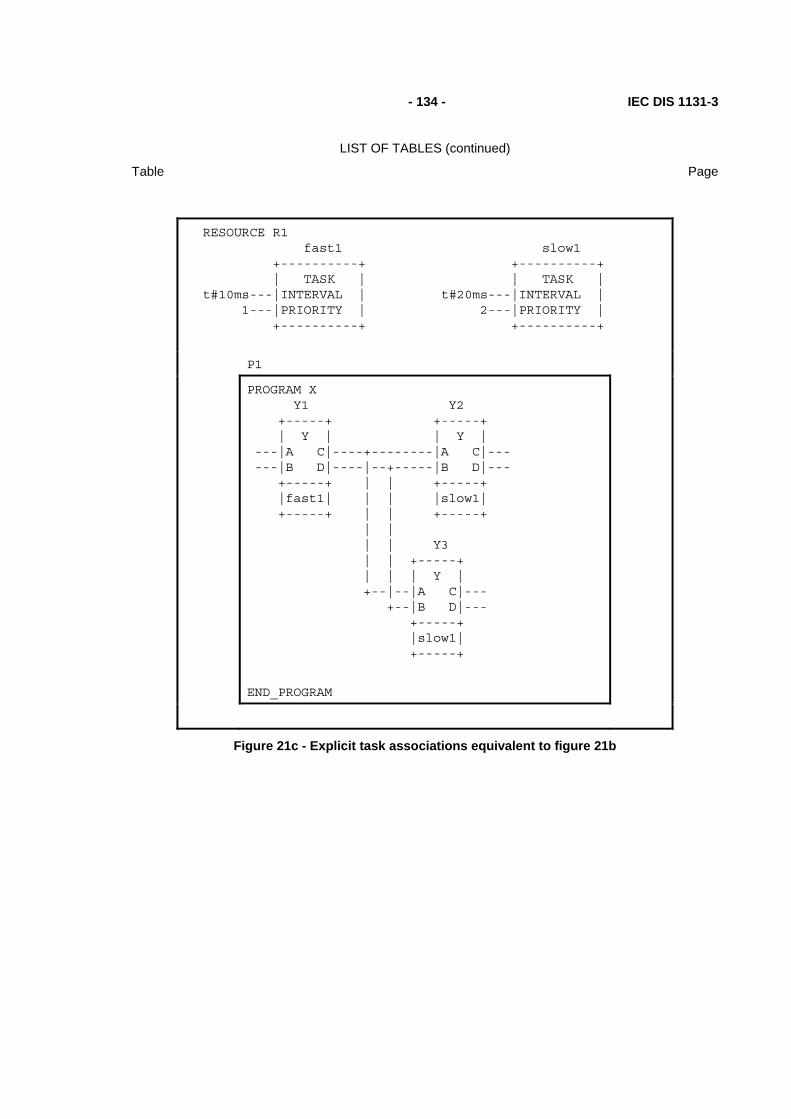
- 134 - IEC DIS 1131-3
LIST OF TABLES (continued)
Table Page
RESOURCE R1 fast1 +----------+ | TASK | t#10ms---|INTERVAL | 1---|PRIORITY | +----------+
slow1 +----------+ | TASK | t#20ms---|INTERVAL | 2---|PRIORITY | +----------+
P1
PROGRAM X Y1 Y2 +-----+ +-----+ | Y | | Y | ---|A C|----+--------|A C|--- ---|B D|----|--+-----|B D|--- +-----+ | | +-----+ |fast1| | | |slow1| +-----+ | | +-----+ | | | | Y3 | | +-----+ | | | Y | +--|--|A C|--- +--|B D|--- +-----+ |slow1| +-----+
END_PROGRAM
Figure 21c - Explicit task associations equivalent to figure 21b

IEC DIS 1131-3 - 135 -
LIST OF TABLES (continued)
Table Page
3. Textual languages
The textual languages defined in this standard are IL (Instruction List) and ST (Structured Text). The sequential function chart (SFC) elements defined in 2.6 can be used in conjunction with either of these languages.
3.1 Common elements
The textual elements specified in clause 2 shall be common to the textual languages (IL and ST) defined in this clause. In particular, the following program structuring elements shall be common to textual languages:
TYPE...END_TYPE (2.3.3)
VAR...END_VAR (2.4.3)
VAR_INPUT...END_VAR (2.4.3)
VAR_OUTPUT...END_VAR (2.4.3)
VAR_IN_OUT...END_VAR (2.4.3)
VAR_EXTERNAL...END_VAR (2.4.3)
FUNCTION ... END_FUNCTION (2.5.1.3)
FUNCTION_BLOCK...END_FUNCTION_BLOCK (2.5.2.2)
PROGRAM...END_PROGRAM (2.5.3)
STEP...END_STEP (2.6.2)
TRANSITION...END_TRANSITION (2.6.3)
ACTION...END_ACTION (2.6.4)

- 136 - IEC DIS 1131-3
LIST OF TABLES (continued)
Table Page
3.2 Language IL (Instruction List)
This subclause defines the semantics of the IL (Instruction List) language whose formal syntax is given in B.2.
3.2.1 Instructions
As illustrated in table 51, an instruction list is composed of a sequence of instructions. Each instruction shall begin on a new line and shall contain an operator with optional modifiers, and, if necessary for the particular operation, one or more operands separated by commas. Operands can be any of the data representations defined in 2.2 for literals and 2.4 for variables.
The instruction can be preceded by an identifying label followed by a colon (:). A comment, as defined in 2.1.5, if present, shall be the last element on a line. Empty lines can be inserted between instructions.
Table 51 - Examples of instruction fields
Label Operator Operand Comment
START: LD %IX1 (* PUSH BUTTON *)
ANDN %MX5 (* NOT INHIBITED *)
ST %QX2 (* FAN ON *)
3.2.2 Operators, modifiers and operands
Standard operators with their allowed modifiers and operands shall be as listed in table 52. The typing of operators shall conform to the conventions of 2.5.1.4.
Unless otherwise defined in table 52, the semantics of the operators shall be result := result OP operand
That is, the value of the expression being evaluated is replaced by its current value operated upon by the operator with respect to the operand. For instance, the instruction AND %IX1 is interpreted as
result := result AND %IX1
The comparison operators shall be interpreted with the current result to the left of the comparison and the operand to the right, with a Boolean result. For instance, the instruction "GT %IW10" will have the Boolean result 1 if the current result is greater than the value of Input Word 10, and the Boolean result 0 otherwise.
The modifier "N" indicates Boolean negation of the operand. For instance, the instruction ANDN %IX2 is interpreted as
result := result AND NOT %IX2

IEC DIS 1131-3 - 137 -
LIST OF TABLES (continued)
Table Page
The left parenthesis modifier "(" indicates that evaluation of the operator shall be deferred until a right parenthesis operator ")" is encountered, e.g., the sequence of instructions
AND( %IX1 OR %IX2 )
shall be interpreted as result := result AND (%IX1 OR %IX2)
The modifier "C" indicates that the associated instruction shall be performed only if the value of the currently evaluated result is Boolean 1 (or Boolean 0 if the operator is combined with the "N" modifier).
Table 52 - Instruction List (IL) operators
No. Operator Modifiers Operand Semantics
1 LD N Note 2 Set current result equal to operand 2 ST N Note 2 Store current result to operand location 3 S Note 3 BOOL Set Boolean operand to 1 R Note 3 BOOL Reset Boolean operand to 0
4 AND N, ( BOOL Boolean AND 5 & N, ( BOOL Boolean AND 6 OR N, ( BOOL Boolean OR 7 XOR N, ( BOOL Boolean Exclusive OR 8 ADD ( Note 2 Addition 9 SUB ( Note 2 Subtraction 10 MUL ( Note 2 Multiplication 11 DIV ( Note 2 Division 12 GT ( Note 2 Comparison: > 13 GE ( Note 2 Comparison: >= 14 EQ ( Note 2 Comparison: = 15 NE ( Note 2 Comparison: <> 16 LE ( Note 2 Comparison: <= 17 LT ( Note 2 Comparison: < 18 JMP C, N LABEL Jump to label 19 CAL C, N NAME Call function block (note 4) 20 RET C, N Return from called function or function block 21 ) Evaluate deferred operation
NOTES
1 - See 3.2.2 for explanation of modifiers and evaluation of expressions. 2 - These operators shall be either overloaded or typed as defined in 2.5.1.4. The current result
and the operand shall be of the same type. 3 - These operations are performed if and only if the value of the current result is Boolean 1. 4 - The function block name is followed by a parenthesized argument list as defined in 3.2.3. 5 - When a JMP instruction is contained in an ACTION... END_ACTION construct, the operand
shall be a label within the same construct.
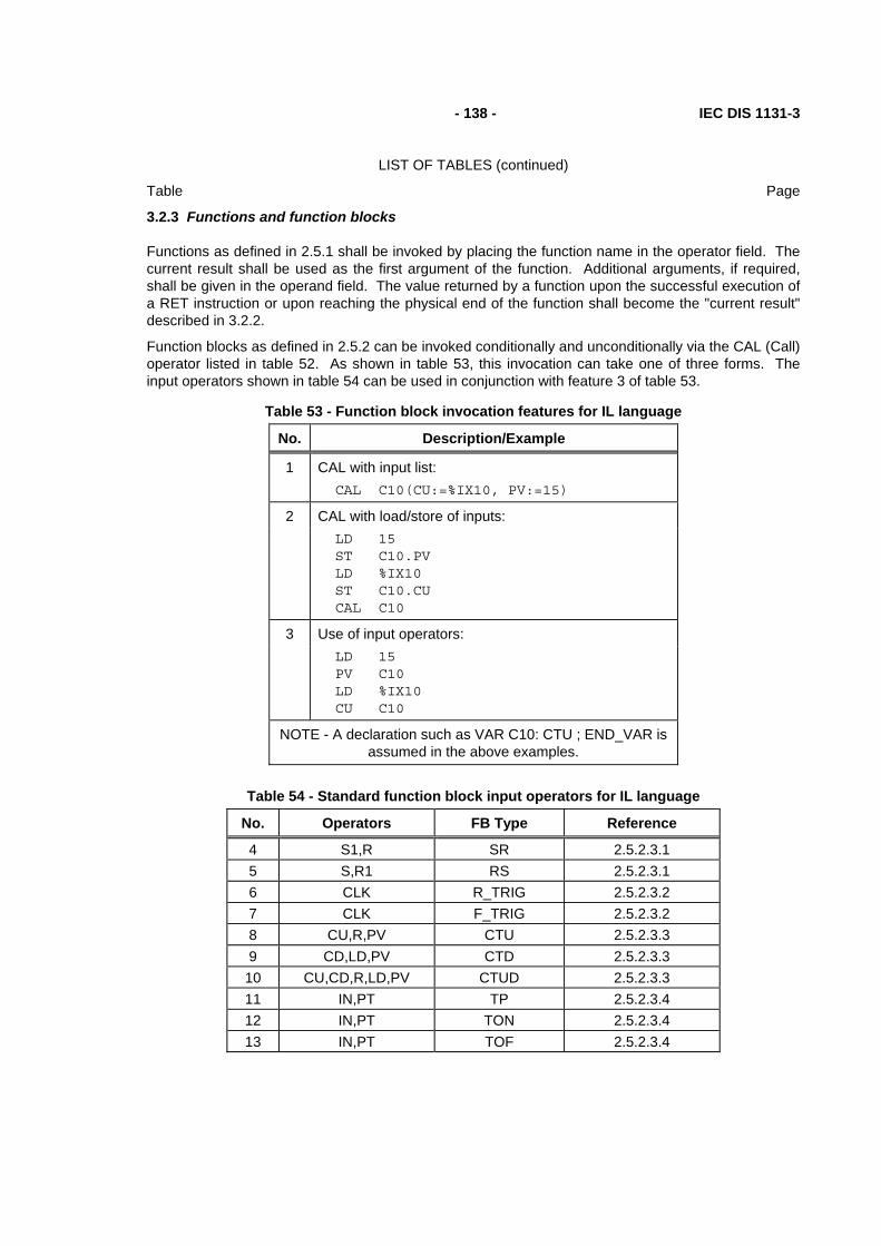
- 138 - IEC DIS 1131-3
LIST OF TABLES (continued)
Table Page
3.2.3 Functions and function blocks
Functions as defined in 2.5.1 shall be invoked by placing the function name in the operator field. The current result shall be used as the first argument of the function. Additional arguments, if required, shall be given in the operand field. The value returned by a function upon the successful execution of a RET instruction or upon reaching the physical end of the function shall become the "current result" described in 3.2.2.
Function blocks as defined in 2.5.2 can be invoked conditionally and unconditionally via the CAL (Call) operator listed in table 52. As shown in table 53, this invocation can take one of three forms. The input operators shown in table 54 can be used in conjunction with feature 3 of table 53.
Table 53 - Function block invocation features for IL language
No. Description/Example
1 CAL with input list: CAL C10(CU:=%IX10, PV:=15)
2 CAL with load/store of inputs: LD 15
ST C10.PV LD %IX10 ST C10.CU CAL C10
3 Use of input operators: LD 15
PV C10 LD %IX10 CU C10
NOTE - A declaration such as VAR C10: CTU ; END_VAR is assumed in the above examples.
Table 54 - Standard function block input operators for IL language
No. Operators FB Type Reference
4 S1,R SR 2.5.2.3.1 5 S,R1 RS 2.5.2.3.1 6 CLK R_TRIG 2.5.2.3.2 7 CLK F_TRIG 2.5.2.3.2 8 CU,R,PV CTU 2.5.2.3.3 9 CD,LD,PV CTD 2.5.2.3.3 10 CU,CD,R,LD,PV CTUD 2.5.2.3.3 11 IN,PT TP 2.5.2.3.4 12 IN,PT TON 2.5.2.3.4 13 IN,PT TOF 2.5.2.3.4
IEC DIS 1131-3 - 139 -
LIST OF TABLES (continued)
Table Page
3.3 Language ST (Structured Text)
This subclause defines the semantics of the ST (Structured Text) language whose syntax is defined in B.3. In this language, the end of a textual line shall be treated the same as a space (SP) character, as defined in 2.1.4.
3.3.1 Expressions
An expression is a construct which, when evaluated, yields a value corresponding to one of the data types defined in 2.3.1 and 2.3.3.
Expressions are composed of operators and operands. An operand shall be a literal as defined in 2.2, a variable as defined in 2.4, a function invocation as defined in 2.5.1, or another expression.
The operators of the ST language are summarized in table 55. The evaluation of an expression consists of applying the operators to the operands in a sequence defined by the operator precedence shown in table 55. The operator with highest precedence in an expression shall be applied first, followed by the operator of next lower precedence, etc., until evaluation is complete. Operators of equal precedence shall be applied as written in the expression from left to right. For example, if A, B, C, and D are of type INT with values 1, 2, 3, and 4, respectively, then
A+B-C*ABS(D) shall evaluate to -9, and
(A+B-C)*ABS(D) shall evaluate to 0 .
When an operator has two operands, the leftmost operand shall be evaluated first. For example, in the expression
SIN(A)*COS(B) the expression SIN(A) shall be evaluated first, followed by COS(B), followed by evaluation of the product.
Boolean expressions may be evaluated only to the extent necessary to determine the resultant value. For instance, if A<=B, then only the expression (A>B) would be evaluated to determine that the value of the expression
(A>B) & (C<D) is Boolean zero.
Functions shall be invoked as elements of expressions consisting of the function name followed by a parenthesized list of arguments, as defined in 2.5.1.1.
When an operator in an expression can be represented as one of the overloaded functions defined in 2.5.1.5, conversion of operands and results shall follow the rule and examples given in 2.5.1.4.

- 140 - IEC DIS 1131-3
LIST OF TABLES (continued)
Table Page
TABLE 55 - Operators of the ST language
No. Operation Symbol Precedence
1 Parenthesization (expression) HIGHEST
2 Function evaluation identifier(argument list)
Examples: LN(A), MAX(X,Y), etc.
3 Exponentiation (Note 2) **
4 Negation -
5 Complement NOT
6 Multiply *
7 Divide /
8 Modulo MOD
9 Add +
10 Subtract -
11 Comparison < , > , <= , >=
12 Equality =
13 Inequality <>
14 Boolean AND &
15 Boolean AND AND
16 Boolean Exclusive OR XOR
17 Boolean OR OR LOWEST
NOTES
1 - The same restrictions apply to the operands of these operators as to the inputs of the corresponding functions defined in 2.5.1.5.
2 - The result of evaluating the expression A**B shall be the same as the result of evaluating the function EXPT(A,B) as defined in table 24.
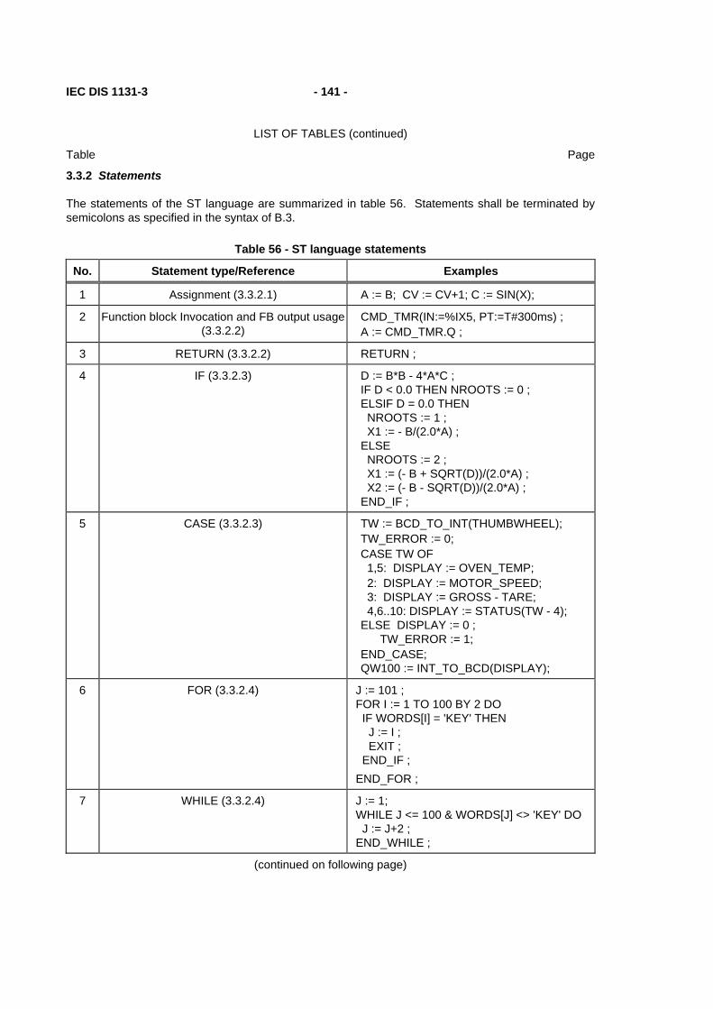
IEC DIS 1131-3 - 141 -
LIST OF TABLES (continued)
Table Page
3.3.2 Statements
The statements of the ST language are summarized in table 56. Statements shall be terminated by semicolons as specified in the syntax of B.3.
Table 56 - ST language statements
No. Statement type/Reference Examples
1 Assignment (3.3.2.1) A := B; CV := CV+1; C := SIN(X);
2
Function block Invocation and FB output usage (3.3.2.2)
CMD_TMR(IN:=%IX5, PT:=T#300ms) ; A := CMD_TMR.Q ;
3 RETURN (3.3.2.2) RETURN ;
4
IF (3.3.2.3)
D := B*B - 4*A*C ; IF D < 0.0 THEN NROOTS := 0 ; ELSIF D = 0.0 THEN NROOTS := 1 ; X1 := - B/(2.0*A) ; ELSE NROOTS := 2 ; X1 := (- B + SQRT(D))/(2.0*A) ; X2 := (- B - SQRT(D))/(2.0*A) ; END_IF ;
5 CASE (3.3.2.3) TW := BCD_TO_INT(THUMBWHEEL); TW_ERROR := 0; CASE TW OF 1,5: DISPLAY := OVEN_TEMP; 2: DISPLAY := MOTOR_SPEED; 3: DISPLAY := GROSS - TARE; 4,6..10: DISPLAY := STATUS(TW - 4); ELSE DISPLAY := 0 ; TW_ERROR := 1; END_CASE; QW100 := INT_TO_BCD(DISPLAY);
6 FOR (3.3.2.4) J := 101 ; FOR I := 1 TO 100 BY 2 DO IF WORDS[I] = 'KEY' THEN J := I ; EXIT ; END_IF ; END_FOR ;
7 WHILE (3.3.2.4) J := 1; WHILE J <= 100 & WORDS[J] <> 'KEY' DO J := J+2 ; END_WHILE ;
(continued on following page)

- 142 - IEC DIS 1131-3
LIST OF TABLES (continued)
Table Page
Table 56 - ST language statements (continued)
No. Statement type/Reference Examples
8 REPEAT (3.3.2.4) J := -1 ; REPEAT J := J+2 ; UNTIL J = 101 OR WORDS[J] = 'KEY' END_REPEAT ;
9 EXIT (3.3.2.4) EXIT ;
10 Empty Statement ;
NOTE - If the EXIT statement (9) is supported, then it shall be supported for all of the iteration statements (FOR, WHILE, REPEAT) which are supported in the implementation.
3.3.2.1 Assignment statements
The assignment statement replaces the current value of a single or multi-element variable by the result of evaluating an expression. An assignment statement shall consist of a variable reference on the left-hand side, followed by the assignment operator ":=", followed by the expression to be evaluated. For instance, the statement
A := B ; would be used to replace the single data value of variable A by the current value of variable B if both were of type INT. However, if both A and B were of type ANALOG_CHANNEL_CONFIGURATION as described in table 12, then the values of all the elements of the structured variable A would be replaced by the current values of the corresponding elements of variable B.
As illustrated in figure 6, the assignment statement shall also be used to assign the value to be returned by a function, by placing the function name to the left of an assignment operator in the body of the function declaration. The value returned by the function shall be the result of the most recent evaluation of such an assignment. It is an error to return from the evaluation of a function with the " ENO" output non-zero unless at least one such assignment has been made.
3.3.2.2 Function and function block control statements
Function and function block control statements consist of the mechanisms for invoking function blocks and for returning control to the invoking entity before the physical end of a function or function block.
Function evaluation shall be invoked as part of expression evaluation, as specified in 3.3.1.
Function blocks shall be invoked by a statement consisting of the name of the function block followed by a parenthesized list of named input parameter value assignments, as illustrated in table56. The order in which input parameters are listed in a function block invocation shall not be significant. It is not required that all input parameters be assigned values in every invocation of a function block. If a particular parameter is not assigned a value in a function block invocation, the previously assigned value (or the initial value, if no previous assignment has been made) shall apply.
The RETURN statement shall provide early exit from a function , function block or program (e.g., as the result of the evaluation of an IF statement).

IEC DIS 1131-3 - 143 -
LIST OF TABLES (continued)
Table Page
3.3.2.3 Selection statements
Selection statements include the IF and CASE statements. A selection statement selects one (or a group) of its component statements for execution, based on a specified condition. Examples of selection statements are given in table 56.
The IF statement specifies that a group of statements is to be executed only if the associated Boolean expression evaluates to the value 1 (true). If the condition is false, then either no statement is to be executed, or the statement group following the ELSE keyword (or the ELSIF keyword if its associated Boolean condition is true) is to be executed.
The CASE statement consists of an expression which shall evaluate to a variable of type INT (the "selector"), and a list of statement groups, each group being labeled by one or more integers or ranges of integer values. It specifies that the first group of statements, one of whose ranges contains the computed value of the selector, shall be executed . If the value of the selector does not occur in a range of any case, the statement sequence following the keyword ELSE (if it occurs in the CASE statement) shall be executed. Otherwise, none of the statement sequences shall be executed.
3.3.2.4 Iteration statements
Iteration statements specify that the group of associated statements shall be executed repeatedly. The FOR statement is used if the number of iterations can be determined in advance; otherwise, the WHILE or REPEAT constructs are used.
The EXIT statement shall be used to terminate iterations before the termination condition is satisfied.
When the EXIT statement is located within nested iterative constructs, exit shall be from the innermost loop in which the EXIT is located, that is, control shall pass to the next statement after the first loop terminator (END_FOR, END_WHILE, or END_REPEAT) following the EXIT statement. For instance, after executing the statements shown in figure 22, the value of the variable SUM shall be 15 if the value of the Boolean variable FLAG is 0, and 6 if FLAG=1.
SUM := 0 ; FOR I := 1 TO 3 DO FOR J := 1 TO 2 DO IF FLAG THEN EXIT ; END_IF SUM := SUM + J ; END_FOR ; SUM := SUM + I ; END_FOR ;
Figure 22 - EXIT statement example
- 144 - IEC DIS 1131-3
LIST OF TABLES (continued)
Table Page
The FOR statement indicates that a statement sequence shall be repeatedly executed, up to the END_FOR keyword, while a progression of values is assigned to the FOR loop control variable. The control variable, initial value, and final value shall be expressions of the same integer type (SINT, INT, or DINT) and shall not be altered by any of the repeated statements. The FOR statement increments the control variable up or down from an initial value to a final value in increments determined by the value of an expression; this value defaults to 1. The test for the termination condition is made at the beginning of each iteration, so that the statement sequence is not executed if the initial value exceeds the final value. The value of the control variable after completion of the FOR loop is implementation-dependent.
An example of the usage of the FOR statement is given in feature 6 of table 56. In this example, the FOR loop is used to determine the index J of the first occurrence (if any) of the string 'KEY' in the odd-numbered elements of an array of strings WORDS with a subscript range of (1..100). If no occurrence is found, J will have the value 101.
The WHILE statement causes the sequence of statements up to the END_WHILE keyword to be executed repeatedly until the associated Boolean expression is false. If the expression is initially false, then the group of statements is not executed at all. For instance, the FOR...END_FOR example given in table 56 can be rewritten using the WHILE...END_WHILE construction shown in table 56.
The REPEAT statement causes the sequence of statements up to the UNTIL keyword to be executed repeatedly (and at least once) until the associated Boolean condition is true. For instance, the WHILE...END_WHILE example given in table 56 can be rewritten using the REPEAT...END_REPEAT construction shown in table 56.
The WHILE and REPEAT statements shall not be used to achieve interprocess synchronization, for example as a "wait loop" with an externally determined termination condition. The SFC elements defined in 2.6 shall be used for this purpose.
It shall be an error in the sense of 1.5.1 if a WHILE or REPEAT statement is used in an algorithm for which satisfaction of the loop termination condition or execution of an EXIT statement cannot be guaranteed.

IEC DIS 1131-3 - 145 -
LIST OF TABLES (continued)
Table Page
4. Graphic languages
The graphic languages defined in this standard are LD (Ladder Diagram) and FBD (Function Block Diagram). The sequential function chart (SFC) elements defined in 2.6 can be used in conjunction with either of these languages.
4.1 Common elements
The elements defined in this clause apply to both the graphic languages in this Standard, that is, LD (Ladder Diagram) and FBD (Function Block Diagram), and to the graphic representation of sequential function chart (SFC) elements.
4.1.1 Representation of lines and blocks
The graphic language elements defined in this clause are drawn with line elements using characters from the ISO/IEC 646 character set, or using graphic or semigraphic elements, as shown in table 57.
Lines can be extended by the use of connectors as shown in table 57. No storage of data or association with data elements shall be associated with the use of connectors; hence, to avoid ambiguity, it shall be an error if the identifier used as a connector label is the same as the name of another named element within the same program organization unit.
4.1.2 Direction of flow in networks
A network is defined as a maximal set of interconnected graphic elements, excluding the left and right rails in the case of networks in the LD language defined in 4.2. Provision shall be made to associate with each network or group of networks in a graphic language a network label delimited on the right by a colon (:). This label shall have the form of an identifier or an unsigned decimal integer as defined in clause 2 of this Part. The scope of a network and its label shall be local to the program organization unit in which the network is located. Examples of networks and network labels are shown in annex F.
Graphic languages are used to represent the flow of a conceptual quantity through one or more networks representing a control plan, that is:
- "Power flow", analogous to the flow of electric power in an electromechanical relay system, typically used in relay ladder diagrams;
- "Signal flow", analogous to the flow of signals between elements of a signal processing system, typically used in function block diagrams;
- "Activity flow", analogous to the flow of control between elements of an organization, or between the steps of an electromechanical sequencer, typically used in sequential function charts.
The appropriate conceptual quantity shall flow along lines between elements of a network according to the following rules:
1) Power flow in the LD language shall be from left to right.
2) Signal flow in the FBD language shall be from the output (right-hand) side of a function or function block to the input (left-hand) side of the function or function block(s) so connected.
3) Activity flow between the SFC elements defined in 2.6 shall be from the bottom of a step through the appropriate transition to the top of the corresponding successor step(s).

- 146 - IEC DIS 1131-3
LIST OF TABLES (continued)
Table Page
Table 57 - Representation of lines and blocks
No. Feature Example
1
2
Horizontal lines: ISO / IEC 646 "minus" character
Graphic or semigraphic
-----
3
4
Vertical lines: ISO / IEC 646 "vertical line" character
Graphic or semigraphic
|
5
6
Horizontal/vertical connection: ISO / IEC 646 "plus" character
Graphic or semigraphic
| --+-- |
7
8
Line crossings without connection: ISO / IEC 646 characters
Graphic or semigraphic
| | --------|----
| |
9
10
Connected and non-connected corners:
ISO / IEC 646 characters
Graphic or semigraphic
| | ----+ +---- | ----+-+ +---- | | |
11
12
Blocks with connecting lines:
ISO / IEC 646 characters
Graphic or semigraphic
| +--------+ ---| | | |--- ---| | +--------+ |
13
14
Connectors using ISO / IEC 646 characters: Connector
Continuation of a connected line
Graphic or semigraphic connectors
---------->OTTO> >OTTO>----------
IEC DIS 1131-3 - 147 -
LIST OF TABLES (continued)
Table Page
4.1.3 Evaluation of networks
The order in which networks and their elements are evaluated is not necessarily the same as the order in which they are labeled or displayed. Similarly, it is not necessary that all networks be evaluated before the evaluation of a given network can be repeated. However, when the body of a program organization unit consists of one or more networks, the results of network evaluation within said body shall be functionally equivalent to the observance of the following rules:
1) No element of a network shall be evaluated until the states of all of its inputs have been evaluated.
2) The evaluation of a network element shall not be complete until the states of all of its outputs have been evaluated.
3) The evaluation of a network is not complete until the outputs of all of its elements have been evaluated, even if the network contains one of the execution control elements defined in 4.1.4.
(4) The order in which networks are evaluated shall conform to the provisions of 4.2.6 for the LD language and 4.3.3 for the FBD language.
A feedback path is said to exist in a network when the output of a function or function block is used as the input to a function or function block which precedes it in the network; the associated variable is called a feedback variable. For instance, the Boolean variable RUN is the feedback variable in the example shown in figure 23. A feedback variable can also be an output element of a function block data structure as defined in 2.5.2.
Feedback paths can be utilized in the graphic languages defined in 4.2 and 4.3, subject to the following rules:
1) Explicit loops such as the one shown in 23a shall only appear in the FBD language defined in 4.3.
2) It shall be possible for the user to define the order of execution of the elements in an explicit loop, for instance by selection of feedback variables to form an implicit loop as shown in figure 23b.
3) Feedback variables shall be initialized by one of the mechanisms defined in clause 2. The initial value shall be used during the first evaluation of the network.
4) Once the element with a feedback variable as output has been evaluated, the new value of the feedback variable shall be used until the next evaluation of the element.
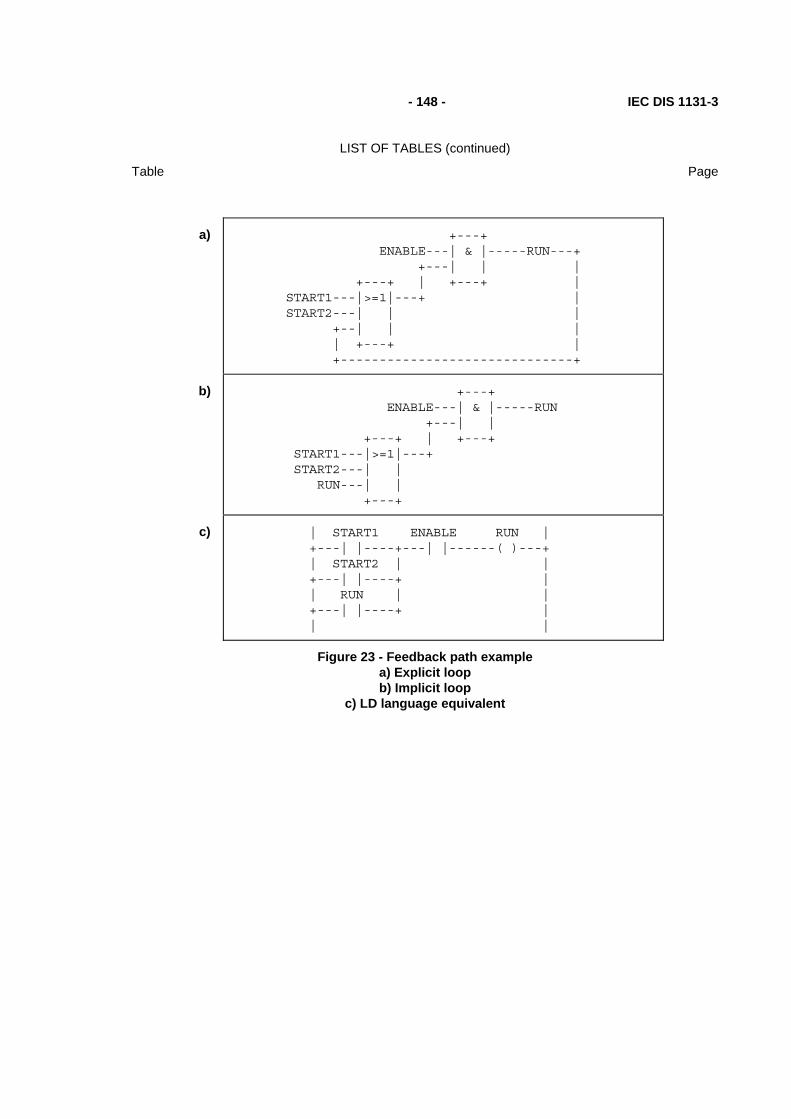
- 148 - IEC DIS 1131-3
LIST OF TABLES (continued)
Table Page
a) +---+ ENABLE---| & |-----RUN---+ +---| | | +---+ | +---+ | START1---|>=1|---+ | START2---| | | +--| | | | +---+ | +------------------------------+
b) +---+ ENABLE---| & |-----RUN +---| | +---+ | +---+ START1---|>=1|---+ START2---| | RUN---| | +---+
c) | START1 ENABLE RUN | +---| |----+---| |------( )---+ | START2 | | +---| |----+ | | RUN | | +---| |----+ | | |
Figure 23 - Feedback path example a) Explicit loop b) Implicit loop
c) LD language equivalent

IEC DIS 1131-3 - 149 -
LIST OF TABLES (continued)
Table Page
4.1.4 Execution control elements
Transfer of program control in the LD and FBD languages shall be represented by the graphical elements shown in table 58.
Jumps shall be shown by a Boolean signal line terminated in a double arrowhead. The signal line for a jump condition shall originate at a Boolean variable, at a Boolean output of a function or function block, or on the power flow line of a ladder diagram. A transfer of program control to the designated network label shall occur when the Boolean value of the signal line is 1 (TRUE); thus, the unconditional jump is a special case of the conditional jump.
The target of a jump shall be a network label within the program organization unit within which the jump occurs. If the jump occurs within an ACTION...END_ACTION construct, the target of the jump shall be within the same construct.
Conditional returns from functions and function blocks shall be implemented using a RETURN construction as shown in table 58. Program execution shall be transferred back to the invoking entity when the Boolean input is 1 (TRUE), and shall continue in the normal fashion when the Boolean input is 0 (FALSE). Unconditional returns shall be provided by the physical end of the function or function block, or by a RETURN element connected to the left rail in the LD language, as shown in table 58.

- 150 - IEC DIS 1131-3
LIST OF TABLES (continued)
Table Page
Table 58 - Graphic execution control elements
No. Symbol/Example Explanation
1
2
1---->>LABELA
| +---->>LABELA |
Unconditional Jump: FBD Language
LD Language
3
X---->>LABELB
+---+ %IX20---| & |--->>NEXT %MX50---| | +---+ NEXT: +---+ %IX25---|>=1|---%QX100 %MX60---| | +---+
Conditional Jump (FBD Language)
Example: Jump Condition
Jump Target
4
| X +-| |---->>LABELB | | | %IX20 %MX50 +---| |-----| |--->>NEXT | | NEXT: | %IX25 %QX100 | +----| |----+----( )---+ | %MX60 | | +----| |----+ | | |
Conditional Jump (LD Language)
Example: Jump Condition
Jump Target
5
6
| X +--| |---<RETURN> |
X---<RETURN>
Conditional Return: LD Language
FBD Language
7
8
END_FUNCTION
END_FUNCTION_BLOCK
| +---<RETURN> |
Unconditional Return:
from FUNCTION
from FUNCTION_BLOCK
Alternative representation in LD language
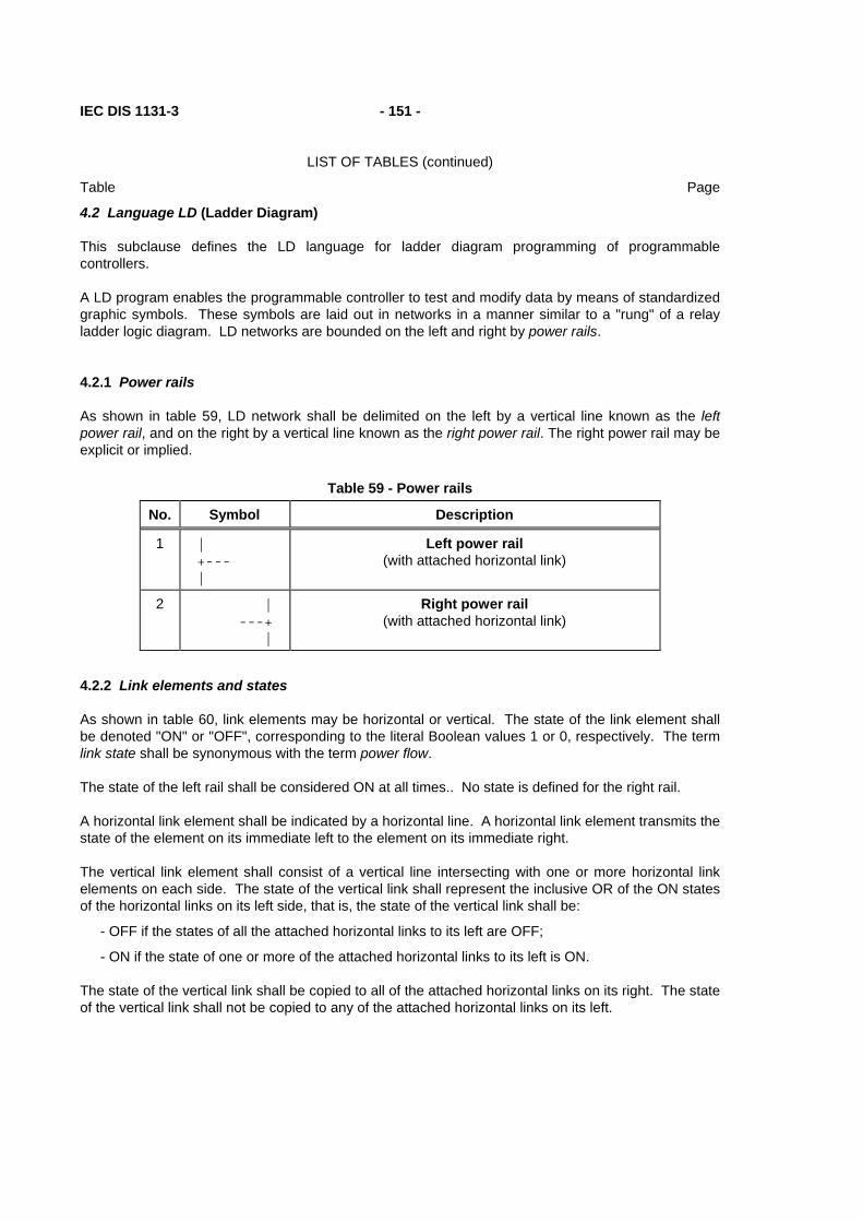
IEC DIS 1131-3 - 151 -
LIST OF TABLES (continued)
Table Page
4.2 Language LD (Ladder Diagram)
This subclause defines the LD language for ladder diagram programming of programmable controllers.
A LD program enables the programmable controller to test and modify data by means of standardized graphic symbols. These symbols are laid out in networks in a manner similar to a "rung" of a relay ladder logic diagram. LD networks are bounded on the left and right by power rails.
4.2.1 Power rails
As shown in table 59, LD network shall be delimited on the left by a vertical line known as the left power rail, and on the right by a vertical line known as the right power rail. The right power rail may be explicit or implied.
Table 59 - Power rails
No. Symbol Description
1
| +--- |
Left power rail (with attached horizontal link)
2
| ---+ |
Right power rail (with attached horizontal link)
4.2.2 Link elements and states
As shown in table 60, link elements may be horizontal or vertical. The state of the link element shall be denoted "ON" or "OFF", corresponding to the literal Boolean values 1 or 0, respectively. The term link state shall be synonymous with the term power flow.
The state of the left rail shall be considered ON at all times.. No state is defined for the right rail.
A horizontal link element shall be indicated by a horizontal line. A horizontal link element transmits the state of the element on its immediate left to the element on its immediate right.
The vertical link element shall consist of a vertical line intersecting with one or more horizontal link elements on each side. The state of the vertical link shall represent the inclusive OR of the ON states of the horizontal links on its left side, that is, the state of the vertical link shall be:
- OFF if the states of all the attached horizontal links to its left are OFF;
- ON if the state of one or more of the attached horizontal links to its left is ON.
The state of the vertical link shall be copied to all of the attached horizontal links on its right. The state of the vertical link shall not be copied to any of the attached horizontal links on its left.
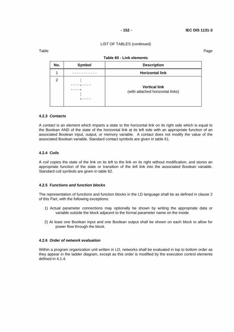
- 152 - IEC DIS 1131-3
LIST OF TABLES (continued)
Table Page
Table 60 - Link elements
No. Symbol Description
1 ----------- Horizontal link
2
| ----+---- ----+ | +----
Vertical link (with attached horizontal links)
4.2.3 Contacts
A contact is an element which imparts a state to the horizontal link on its right side which is equal to the Boolean AND of the state of the horizontal link at its left side with an appropriate function of an associated Boolean input, output, or memory variable. A contact does not modify the value of the associated Boolean variable. Standard contact symbols are given in table 61.
4.2.4 Coils
A coil copies the state of the link on its left to the link on its right without modification, and stores an appropriate function of the state or transition of the left link into the associated Boolean variable. Standard coil symbols are given in table 62.
4.2.5 Functions and function blocks
The representation of functions and function blocks in the LD language shall be as defined in clause 2 of this Part, with the following exceptions:
1) Actual parameter connections may optionally be shown by writing the appropriate data or variable outside the block adjacent to the formal parameter name on the inside.
2) At least one Boolean input and one Boolean output shall be shown on each block to allow for power flow through the block.
4.2.6 Order of network evaluation
Within a program organization unit written in LD, networks shall be evaluated in top to bottom order as they appear in the ladder diagram, except as this order is modified by the execution control elements defined in 4.1.4.
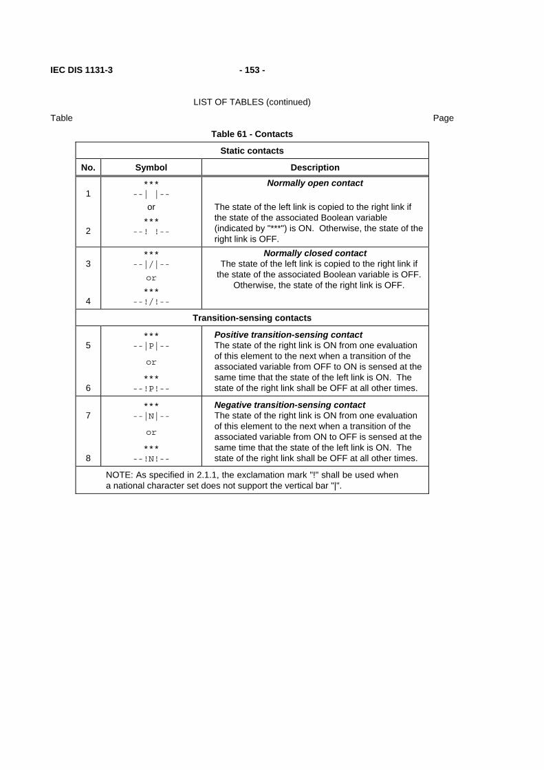
IEC DIS 1131-3 - 153 -
LIST OF TABLES (continued)
Table Page
Table 61 - Contacts
Static contacts
No. Symbol Description
1
2
*** --| |--
or ***
--! !--
Normally open contact The state of the left link is copied to the right link if the state of the associated Boolean variable (indicated by "***") is ON. Otherwise, the state of the right link is OFF.
3
4
*** --|/|--
or
*** --!/!--
Normally closed contact The state of the left link is copied to the right link if
the state of the associated Boolean variable is OFF. Otherwise, the state of the right link is OFF.
Transition-sensing contacts
5
6
*** --|P|--
or
*** --!P!--
Positive transition-sensing contact The state of the right link is ON from one evaluation of this element to the next when a transition of the associated variable from OFF to ON is sensed at the same time that the state of the left link is ON. The state of the right link shall be OFF at all other times.
7
8
*** --|N|--
or
*** --!N!--
Negative transition-sensing contact The state of the right link is ON from one evaluation of this element to the next when a transition of the associated variable from ON to OFF is sensed at the same time that the state of the left link is ON. The state of the right link shall be OFF at all other times.
NOTE: As specified in 2.1.1, the exclamation mark "!" shall be used when a national character set does not support the vertical bar "|".

- 154 - IEC DIS 1131-3
LIST OF TABLES (continued)
Table Page
Table 62 - Coils
Momentary coils
No. Symbol Description
1
*** --( )--
Coil The state of the left link is copied to the associated Boolean variable and to the right link.
2
***
--(/)--
Negated coil The state of the left link is copied to the right link. The inverse of the state of the left link is copied to the associated Boolean variable, that is, if the state of the left link is OFF, then the state of the associated variable is ON, and vice versa.
Latched Coils
3
***
--(S)--
SET (latch) coil The associated Boolean variable is set to the ON state when the left link is in the ON state, and remains set until reset by a RESET coil.
4
*** --(R)--
RESET (unlatch) coil The associated Boolean variable is reset to the OFF state when the left link is in the ON state, and remains reset until set by a SET coil.
Retentive coils (see Note)
5 *** ----(M)----
Retentive (Memory) coil
6
*** ----(SM)----
SET retentive (Memory) coil
7 *** ----(RM)----
RESET retentive (Memory) coil
Transition-sensing coils
8
***
--(P)--
Positive transition-sensing coil The state of the associated Boolean variable is ON from one evaluation of this element to the next when a transition of the left link from OFF to ON is sensed. The state of the left link is always copied to the right link.
9
***
--(N)--
Negative transition-sensing coil The state of the associated Boolean variable is ON from one evaluation of this element to the next when a transition of the left link from ON to OFF is sensed. The state of the left link is always copied to the right link.
NOTE - The action of coils 5, 6, and 7 is identical to that of coils 1, 3, and 4, respectively, except that the associated Boolean variable is automatically declared to be in retentive memory without the explicit use of the VAR RETAIN declaration defined in 2.4.2.

IEC DIS 1131-3 - 155 -
LIST OF TABLES (continued)
Table Page
4.3 Language FBD (Function Block Diagram)
4.3.1 General
This subclause defines FBD, a graphic language for the programming of programmable controllers which is consistent, as far as possible, with IEC 617-12. Where conflicts exist between this standard and IEC 617, the provisions of this standard shall apply for the programming of programmable controllers in the FBD language.
The provisions of clauses 2 and 4.1 shall apply to the construction and interpretation of programmable controller programs in the FBD language.
Examples of the use of the FBD language are given in annex F.
4.3.2 Combination of elements
Elements of the FBD language shall be interconnected by signal flow lines following the conventions of 4.1.2.
Outputs of function blocks shall not be connected together. In particular, the "wired-OR" construct of the LD language is not allowed in the FBD language; an explicit Boolean "OR" block is required instead, as shown in figure 24.
a) b)
| a c | +---||--+--()--+ | b | | +--||---+ | | |
+-----+ a---| >=1 |---c b---| | +-----+
Figure 24 - Boolean OR Examples a) "Wired-OR" in LD language b) Function in FBD language
4.3.3 Order of network evaluation
Within a program organization unit written in the FBD language, the order of network evaluation shall follow the rule that the evaluation of a network shall be complete before starting the evaluation of another network which uses one or more of the outputs of the preceding evaluated network.


IEC DIS 1131-3 - 207 -
ANNEX A - Specification method for textual languages (normative)
Programming languages are specified in terms of a syntax, which specifies the allowable combinations of symbols which can be used to define a program; and a set of semantics, which specify the relationship between programmed operations and the symbol combinations defined by the syntax.
A.1 Syntax
A syntax is defined by a set of terminal symbols to be utilized for program specification; a set of non-terminal symbols defined in terms of the terminal symbols; and a set of production rules specifying those definitions.
A.1.1 Terminal symbols
The terminal symbols for textual programmable controller programs shall consist of combinations of the characters in the ISO/IEC 646 character set. For interchange of programs between systems, these characters shall be represented by the seven-bit character codes defined in ISO 646.
For the purposes of this part, terminal textual symbols consist of the appropriate character string enclosed in paired single or double quotes. For example, a terminal symbol represented by the character string ABC can be represented by either
"ABC" or
'ABC'
This allows the representation of strings containing either single or double quotes; for instance, a terminal symbol consisting of the double quote itself would be represented by '"'.
A special terminal symbol utilized in this syntax is the end-of-line delimiter, which is represented by the unquoted character string EOL. This symbol shall normally consist of the FE5 (CR = carriage return) character defined by ISO/IEC 646. Language implementors shall specify any deviation from this usage; in any case, no characters other than those in ISO/IEC 646 are allowed.
A second special terminal symbol utilized in this syntax is the "null string", that is, a string containing no characters. This is represented by the terminal symbol NIL.
A.1.2 Non-terminal symbols
Non-terminal textual symbols shall be represented by strings of lower-case letters, numbers, and the underline character (_), beginning with a lower-case letter. For instance, the strings
nonterm1 and
non_term_2
are valid non-terminal symbols, while the strings
3nonterm and
_nonterm4 are not.

- 208 - IEC DIS 1131-3
ANNEX G - Index (continued)
A.1.3 Production rules
The production rules for textual programmable controller programming languages shall form an extended grammar in which each rule has the form
non_terminal_symbol ::= extended_structure
This rule can be read as:
"A non_terminal_symbol can consist of an extended_structure."
Extended structures can be constructed according to the following rules:
1) The null string, NIL, is an extended structure.
2) A terminal symbol is an extended structure.
3) A non-terminal symbol is an extended structure.
4) If S is an extended structure, then the following expressions are also extended structures:
(S), meaning S itself.
{S}, closure, meaning zero or more concatenations of S.
[S], option, meaning zero or one occurrence of S.
5) If S1 and S2 are extended structures, then the following expressions are extended structures:
S1|S2, alternation, meaning a choice of S1 or S2.
S1 S2, concatenation, meaning S1 followed by S2.
6) Concatenation precedes alternation, that is, S1 | S2 S3 is equivalent to S1 | (S2 S3), and S1 S2 | S3 is equivalent to (S1 S2) | S3.
A.2 Semantics
Programmable controller textual programming language semantics are defined in this Part by appropriate natural language text, accompanying the production rules, which references the descriptions provided in the appropriate clauses. Standard options available to the user and manufacturer are specified in these semantics.
In some cases it is more convenient to embed semantic information in an extended structure. In such cases, this information is delimited by paired angle brackets, for example, <semantic information>.
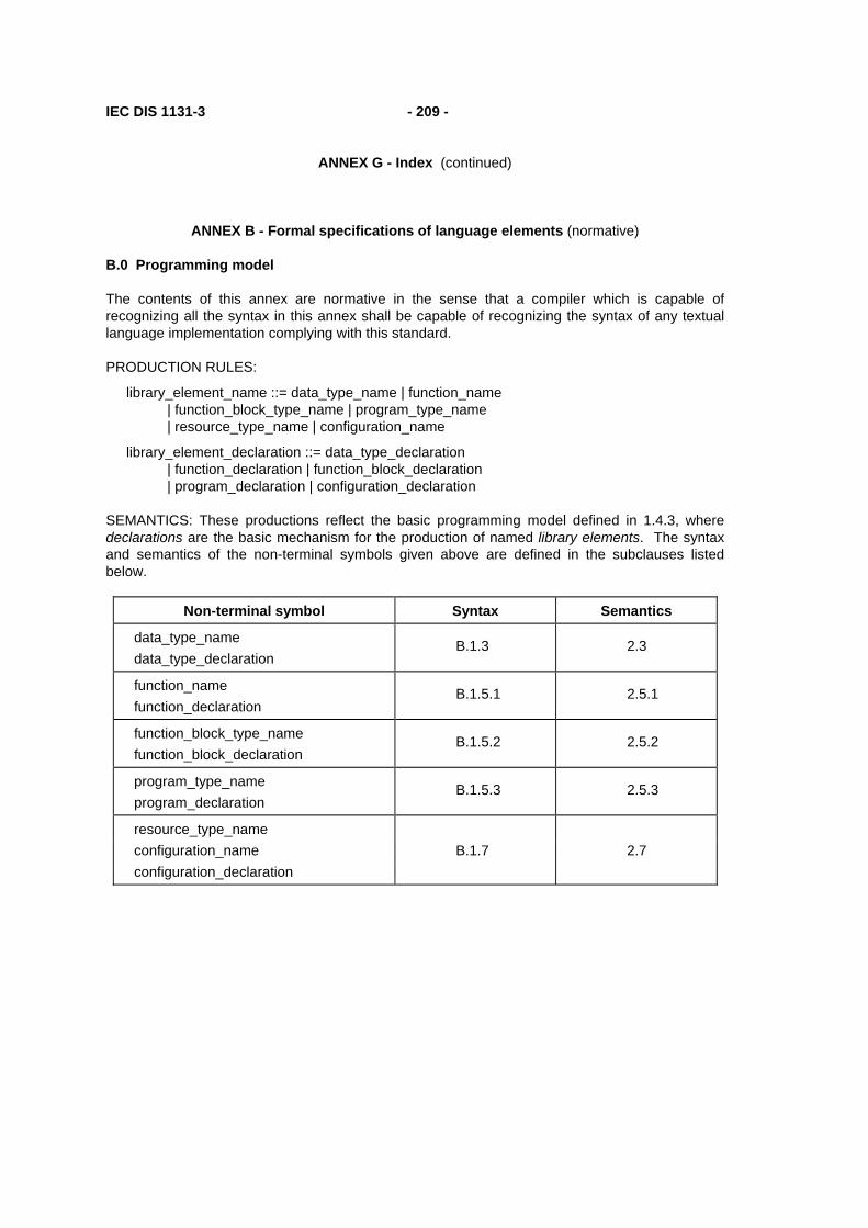
IEC DIS 1131-3 - 209 -
ANNEX G - Index (continued)
ANNEX B - Formal specifications of language elements (normative)
B.0 Programming model
The contents of this annex are normative in the sense that a compiler which is capable of recognizing all the syntax in this annex shall be capable of recognizing the syntax of any textual language implementation complying with this standard.
PRODUCTION RULES:
library_element_name ::= data_type_name | function_name | function_block_type_name | program_type_name | resource_type_name | configuration_name
library_element_declaration ::= data_type_declaration | function_declaration | function_block_declaration | program_declaration | configuration_declaration
SEMANTICS: These productions reflect the basic programming model defined in 1.4.3, where declarations are the basic mechanism for the production of named library elements. The syntax and semantics of the non-terminal symbols given above are defined in the subclauses listed below.
Non-terminal symbol Syntax Semantics
data_type_name data_type_declaration
B.1.3 2.3
function_name function_declaration
B.1.5.1 2.5.1
function_block_type_name function_block_declaration
B.1.5.2 2.5.2
program_type_name program_declaration
B.1.5.3 2.5.3
resource_type_name configuration_name B.1.7 2.7 configuration_declaration

- 210 - IEC DIS 1131-3
ANNEX G - Index (continued)
B.1 Common elements
B.1.1 Letters, digits and identifiers
PRODUCTION RULES:
letter ::= 'A' | 'B' | <...> | 'Z' | 'a' | 'b' | <...> | 'z'
digit ::= '0' | '1' | '2' | '3' | '4' | '5' | '6' | '7' | '8' | '9'
octal_digit ::= '0' | '1' | '2' | '3' | '4' | '5' | '6' | '7'
hex_digit ::= digit | 'A' | 'B' | 'C' | 'D' | 'E' | 'F' | 'a' | 'b' | 'c' | 'd' | 'e' | 'f'
identifier ::= (letter | ('_' (letter | digit))) {['_'] (letter | digit)}
SEMANTICS:
The ellipsis <...> here indicates the ISO/IEC 646 sequence of 26 letters.
Characters from national character sets can be used; however, international portability of the printed representation of programs cannot be guaranteed in this case.
The case of letters shall be significant in terminal symbols, but not in other syntactic elements.
B.1.2 Constants
PRODUCTION RULE:
constant ::= numeric_literal | character_string | time_literal
SEMANTICS:
The external representations of data described in 2.2 are designated as "constants" in this annex.
B.1.2.1 Numeric literals
PRODUCTION RULES:
numeric_literal ::= integer_literal | real_literal | ‘TRUE’ | ‘FALSE’
integer_literal ::= signed_integer | binary_integer | octal_integer | hex_integer
signed_integer ::= ['+' |'-'] integer
integer ::= digit {['_'] digit}
binary_integer ::= '2#' bit {['_'] bit}
bit ::= '1' | '0'
octal_integer ::= '8#' octal_digit {['_'] octal_digit}
hex_integer ::= '16#' hex_digit {['_'] hex_digit}
real_literal ::= signed_integer '.' integer [exponent]
exponent ::= ('E' | 'e') ['+'|'-'] integer
SEMANTICS: See 2.2.1.

IEC DIS 1131-3 - 211 -
ANNEX G - Index (continued)
B.1.2.2 Character strings
PRODUCTION RULES:
character_string ::= " ' " {character_representation} " ' "
character_representation ::= <any printable character except '$'> | '$' hex_digit hex_digit | '$$' | " $' " | '$L' | '$N' | '$P' | '$R' | '$T' | '$l' | '$n' | '$p' | '$r' | '$t'
SEMANTICS: See 2.2.2.
B.1.2.3 Time literals
PRODUCTION RULE:
time_literal ::= duration | time_of_day | date | date_and_time
SEMANTICS: See 2.2.3.
B.1.2.3.1 Duration
PRODUCTION RULES:
duration ::= ('T' | 't' | 'TIME' | 'time') '#' ['-'] interval
interval ::= days | hours | minutes | seconds | milliseconds
days ::= fixed_point ('d' | 'D') | integer ('d' | 'D') ['_'] hours
fixed_point ::= integer [ '.' integer]
hours ::= fixed_point ('h' | 'H') | integer ('h' | 'H') ['_'] minutes
minutes ::= fixed_point ('m' | 'M') | integer ('m' | 'M') ['_'] seconds
seconds ::= fixed_point ('s' | 'S') | integer ('s' | 'S') ['_'] milliseconds
milliseconds ::= fixed_point ('ms' | 'MS')
SEMANTICS: See 2.2.3.1.
NOTE - The semantics of 2.2.3.1 impose additional constraints on the allowable values of hours, minutes, seconds, and milliseconds.
B.1.2.3.2 Time of day and date
PRODUCTION RULES:
time_of_day ::= ('TIME_OF_DAY' | 'time_of_day' | 'TOD' | 'tod') '#' daytime
daytime ::= day_hour ':' day_minute ':' day_second
day_hour ::= integer
day_minute ::= integer
day_second ::= fixed_point
date ::= ('DATE' | 'date' | 'D' | 'd') '#' date_literal
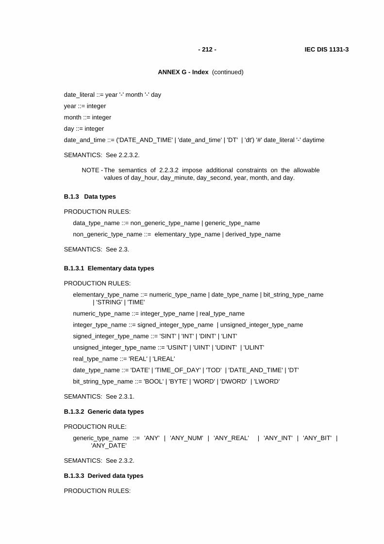
- 212 - IEC DIS 1131-3
ANNEX G - Index (continued)
date_literal ::= year '-' month '-' day
year ::= integer
month ::= integer
day ::= integer
date_and_time ::= ('DATE_AND_TIME' | 'date_and_time' | 'DT' | 'dt') '#' date_literal '-' daytime
SEMANTICS: See 2.2.3.2.
NOTE - The semantics of 2.2.3.2 impose additional constraints on the allowable values of day_hour, day_minute, day_second, year, month, and day.
B.1.3 Data types
PRODUCTION RULES:
data_type_name ::= non_generic_type_name | generic_type_name
non_generic_type_name ::= elementary_type_name | derived_type_name
SEMANTICS: See 2.3.
B.1.3.1 Elementary data types
PRODUCTION RULES:
elementary_type_name ::= numeric_type_name | date_type_name | bit_string_type_name | 'STRING' | 'TIME'
numeric_type_name ::= integer_type_name | real_type_name
integer_type_name ::= signed_integer_type_name | unsigned_integer_type_name
signed_integer_type_name ::= 'SINT' | 'INT' | 'DINT' | 'LINT'
unsigned_integer_type_name ::= 'USINT' | 'UINT' | 'UDINT' | 'ULINT'
real_type_name ::= 'REAL' | 'LREAL'
date_type_name ::= 'DATE' | 'TIME_OF_DAY' | 'TOD' | 'DATE_AND_TIME' | 'DT'
bit_string_type_name ::= 'BOOL' | 'BYTE' | 'WORD' | 'DWORD' | 'LWORD'
SEMANTICS: See 2.3.1.
B.1.3.2 Generic data types
PRODUCTION RULE:
generic_type_name ::= 'ANY' | 'ANY_NUM' | 'ANY_REAL' | 'ANY_INT' | 'ANY_BIT' | 'ANY_DATE'
SEMANTICS: See 2.3.2.
B.1.3.3 Derived data types
PRODUCTION RULES:

IEC DIS 1131-3 - 213 -
ANNEX G - Index (continued)
derived_type_name ::= single_element_type_name | array_type_name | structure_type_name | string_type_name
single_element_type_name ::= simple_type_name | subrange_type_name | enumerated_type_name
simple_type_name ::= identifier subrange_type_name ::= identifier enumerated_type_name ::= identifier array_type_name ::= identifier structure_type_name ::= identifier data_type_declaration ::= 'TYPE' type_declaration ';' {type_declaration ';'} 'END_TYPE' type_declaration ::= single_element_type_declaration | array_type_declaration
| structure_type_declaration | string_type_declaration single_element_type_declaration ::= simple_type_declaration | subrange_type_declaration
| enumerated_type_declaration simple_type_declaration ::= simple_type_name ':' simple_spec_init simple_spec_init := simple_specification [':=' constant] simple_specification ::= elementary_type_name | simple_type_name subrange_type_declaration ::= subrange_type_name ':' subrange_spec_init subrange_spec_init ::= subrange_specification [':=' signed_integer] subrange_specification ::= integer_type_name '(' subrange')' | subrange_type_name subrange ::= signed_integer '..' signed_integer enumerated_type_declaration ::= enumerated_type_name ':' enumerated_spec_init enumerated_spec_init ::= enumerated_specification [':=' enumerated_value] enumerated_specification ::= ( '(' enumerated_value {',' enumerated_value} ')' )
| enumerated_type_name
enumerated_value ::= identifier array_type_declaration ::= array_type_name ':' array_spec_init array_spec_init ::= array_specification [':=' array_initialization] array_specification ::= array_type_name
| 'ARRAY' '[' subrange {',' subrange} ']' 'OF' non_generic_type_name array_initialization ::= [array_initial_elements {',' array_initial_elements}] array_initial_elements ::= array_initial_element | integer '(' array_initial_element ')' array_initial_element ::= constant | enumerated_value | structure_initialization |
array_initialization structure_type_declaration ::= structure_type_name ':' structure_specification structure_specification ::= structure_declaration | initialized_structure initialized_structure ::= structure_type_name [structure_initialization] structure_declaration ::= 'STRUCT' structure_element_declaration ';'
{structure_element_declaration ';'} 'END_STRUCT' structure_element_declaration ::= structure_element_name ':'
(simple_spec_init | subrange_spec_init | enumerated_spec_init | array_spec_init | initialized_structure)
structure_element_name ::= identifier
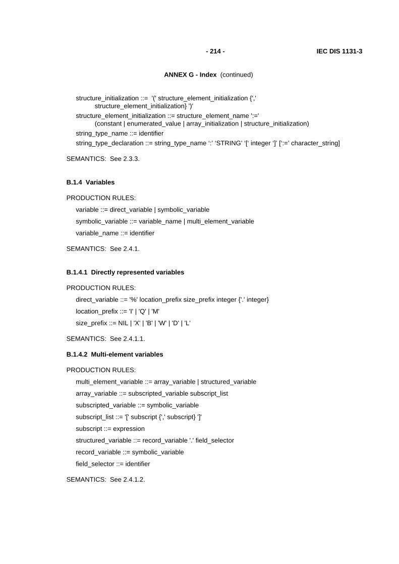
- 214 - IEC DIS 1131-3
ANNEX G - Index (continued)
structure_initialization ::= '(' structure_element_initialization {',' structure_element_initialization} ')'
structure_element_initialization ::= structure_element_name ':=' (constant | enumerated_value | array_initialization | structure_initialization)
string_type_name ::= identifier string_type_declaration ::= string_type_name ‘:’ ‘STRING’ ‘[‘ integer ‘]’ [‘:=’ character_string]
SEMANTICS: See 2.3.3.
B.1.4 Variables
PRODUCTION RULES:
variable ::= direct_variable | symbolic_variable
symbolic_variable ::= variable_name | multi_element_variable
variable_name ::= identifier
SEMANTICS: See 2.4.1.
B.1.4.1 Directly represented variables
PRODUCTION RULES:
direct_variable ::= '%' location_prefix size_prefix integer {'.' integer}
location_prefix ::= 'I' | 'Q' | 'M'
size_prefix ::= NIL | 'X' | 'B' | 'W' | 'D' | 'L'
SEMANTICS: See 2.4.1.1.
B.1.4.2 Multi-element variables
PRODUCTION RULES:
multi_element_variable ::= array_variable | structured_variable
array_variable ::= subscripted_variable subscript_list
subscripted_variable ::= symbolic_variable
subscript_list ::= '[' subscript {',' subscript} ']'
subscript ::= expression
structured_variable ::= record_variable '.' field_selector
record_variable ::= symbolic_variable
field_selector ::= identifier
SEMANTICS: See 2.4.1.2.

IEC DIS 1131-3 - 215 -
ANNEX G - Index (continued)
B.1.4.3 Declaration and initialization
PRODUCTION RULES:
input_declarations ::= 'VAR_INPUT' input_declaration ';' {input_declaration ';'} 'END_VAR'
input_declaration ::= var_init_decl | edge_declaration
edge_declaration ::= var1_list ':' 'BOOL' ['R_EDGE' | 'F_EDGE']
var_init_decl ::= var1_init_decl | array_var_init_decl | structured_var_init_decl | fb_name_decl | string_var_declaration
var1_init_decl ::= var1_list ':' (simple_spec_init | subrange_spec_init | enumerated_spec_init)
var1_list ::= variable_name {',' variable_name}
array_var_init_decl ::= var1_list ':' array_spec_init
structured_var_init_decl ::= var1_list ':' initialized_structure
fb_name_decl ::= fb_name_list ':' function_block_type_name
fb_name_list ::= fb_name {',' fb_name}
fb_name ::= identifier
output_declarations ::= 'VAR_OUTPUT' ['RETAIN'] var_init_decl ';' {var_init_decl ';'} 'END_VAR'
input_output_declarations ::= 'VAR_IN_OUT' var_declaration ';' {var_declaration ';'} 'END_VAR'
var_declaration ::= var1_declaration | array_var_declaration | structured_var_declaration | fb_name_decl
var1_declaration ::= var1_list ':' (simple_specification | subrange_specification | enumerated_specification)
array_var_declaration ::= var1_list ':' array_specification
structured_var_declaration ::= var1_list ':' structure_type_name
var_declarations ::= 'VAR' ['CONSTANT] var_init_decl ';' {(var_init_decl ';')} 'END_VAR'
retentive_var_declarations ::= 'VAR' 'RETAIN' var_init_decl ';' {var_init_decl ';'} 'END_VAR'
located_var_declarations ::= 'VAR' ['CONSTANT' | 'RETAIN'] located_var_decl ';' {located_var_decl ';'} 'END_VAR'
located_var_decl ::= [variable_name] location ':' located_var_spec_init
external_var_declarations := 'VAR_EXTERNAL' external_declaration ';' {external_declaration ';'} 'END_VAR'
external_declaration ::= global_var_name ':' (simple_specification | subrange_specification | enumerated_specification | array_specification | structure_type_name | function_block_type_name)
global_var_name ::= identifier
global_var_declarations := 'VAR_GLOBAL' ['CONSTANT' | 'RETAIN'] global_var_decl ';' {global_var_decl ';'} 'END_VAR'

- 216 - IEC DIS 1131-3
ANNEX G - Index (continued)
global_var_decl ::= global_var_spec ':' [ located_var_spec_init | function_block_type_name ]
global_var_spec ::= global_var_list | [global_var_name] location
located_var_spec_init ::= simple_spec_init | subrange_spec_init | enumerated_spec_init | array_spec_init | initialized_structure
location ::= 'AT' direct_variable
global_var_list ::= global_var_name {',' global_var_name} string_var_declaration ::= variable_name ‘:’ ‘STRING’ ‘[‘ integer ‘]’ [‘:=’ character_string ]
SEMANTICS: See 2.4.2. The non-terminal "function_block_type_name" is defined in B.1.5.2.
B.1.5 Program organization units
B.1.5.1 Functions
PRODUCTION RULES:
function_name ::= standard_function_name | derived_function_name
standard_function_name ::= <as defined in 2.5.1.5>
derived_function_name ::= identifier
function_declaration ::= 'FUNCTION' derived_function_name ':' (elementary_type_name | derived_type_name) input_declarations ['VAR' ['CONSTANT']function_var_decls 'END_VAR'] function_body 'END_FUNCTION'
function_var_decls ::= function_var_decl ';' {function_var_decl ';'}
function_var_decl ::= var1_declaration | array_var_declaration | structured_var_declaration
function_body ::= ladder_diagram | function_block_diagram | instruction_list | statement_list
SEMANTICS: See 2.5.1.
NOTES
1 This syntax does not reflect the fact that function block references and invocations are not allowed in function bodies.
2 Ladder diagrams and function block diagrams are graphically represented as defined in clause 4. The non-terminals instruction_list and statement_list are defined in B.2.1 and B.3.2, respectively.
B.1.5.2 Function blocks
PRODUCTION RULES:
function_block_type_name ::= standard_function_block_name | derived_function_block_name
standard_function_block_name ::= <as defined in 2.5.2.3>
derived_function_block_name ::= identifier

IEC DIS 1131-3 - 217 -
ANNEX G - Index (continued)
function_block_declaration ::= 'FUNCTION_BLOCK' derived_function_block_name {fb_io_var_declarations} {other_var_declarations} function_block_body 'END_FUNCTION_BLOCK'
fb_io_var_declarations ::= input_declarations | output_declarations | input_output_declarations
other_var_declarations ::= external_var_declarations | var_declarations | retentive_var_declarations
function_block_body ::= sequential_function_chart | ladder_diagram | function_block_diagram | instruction_list | statement_list
SEMANTICS: See 2.5.2.
NOTES
1 Ladder diagrams and function block diagrams are graphically represented as defined in clause 4.
2 The non-terminals sequential_function_chart, instruction_list, and statement_list are defined in B.1.6, B.2, and B.3.2, respectively.
B.1.5.3 Programs
PRODUCTION RULES:
program_type_name :: = identifier
program_declaration ::= 'PROGRAM' program_type_name {fb_io_var_declarations} {other_var_declarations | located_var_declarations | global_var_declarations} [program_access_decls] function_block_body 'END_PROGRAM'
program_access_decls ::= 'VAR_ACCESS' program_access_decl ';' {program_access_decl ';' } 'END_VAR'
program_access_decl ::= access_name ':' symbolic_variable ':' non_generic_type_name [direction]
SEMANTICS: See 2.5.3.
B.1.6 Sequential function chart elements
PRODUCTION RULES:
sequential_function_chart ::= sfc_network {sfc_network}

- 218 - IEC DIS 1131-3
ANNEX G - Index (continued)
sfc_network ::= initial_step {step | transition | action}
initial_step ::= 'INITIAL_STEP' step_name ':' {action_association ';'} 'END_STEP'
step ::= 'STEP' step_name ':' {action_association ';'} 'END_STEP'
step_name ::= identifier
action_association ::= action_name '(' action_qualifier {',' indicator_name} ')'
action_name ::= identifier
action_qualifier ::= 'N' | 'R' | 'S' | 'P' | timed_qualifier ',' action_time
timed_qualifier ::= 'L' | 'D' | 'SD' | 'DS' | 'SL'
action_time ::= duration | variable_name
indicator_name ::= variable_name
transition ::= named_transition | unnamed_transition
transition_name ::= identifier
steps ::= step_name | '(' step_name ',' step_name {',' step_name} ')'
transition_condition ::= ':' instruction_list | ':=' expression ';' | ':' (fbd_network | rung)
unnamed_transition ::= ‘TRANSITION’ ‘FROM’ steps ‘TO’ steps transition_condition ‘END_TRANSITION’
named_transition ::= ‘TRANSITION’ transition_name transition_condition
action ::= 'ACTION' action_name ':' function_block_body 'END_ACTION'
SEMANTICS: See 2.6. The use of function block diagram networks and ladder diagram rungs, denoted by the non-terminals fbd_network and rung, respectively, for the expression of transition conditions shall be as defined in 2.6.3.
NOTES
1 The non-terminals instruction_list and expression are defined in B.2.1 and B.3.1, respectively.
2 The construction named_transition can only be used when feature No.7 of table 41 is supported.
B.1.7 Configuration elements
PRODUCTION RULES:
configuration_name ::= identifier
resource_type_name ::= identifier
configuration_declaration ::= 'CONFIGURATION' configuration_name [global_var_declarations] (single_resource_declaration | (resource_declaration {resource_declaration})) [access_declarations] 'END_CONFIGURATION'

IEC DIS 1131-3 - 219 -
ANNEX G - Index (continued)
resource_declaration ::= 'RESOURCE' resource_name 'ON' resource_type_name [global_var_declarations] single_resource_declaration 'END_RESOURCE'
single_resource_declaration ::= {task_configuration ‘;’} program_configuration ‘;’ {program_configuration ‘;’}
resource_name ::= identifier
access_declarations ::= 'VAR_ACCESS' access_declaration ';' {access_declaration ';'} 'END_VAR'
access_declaration ::= access_name ':' access_path ':' non_generic_type_name [direction]
access_path ::= [resource_name '.' ] direct_variable | resource_name '.' program_io_reference | global_var_reference
global_var_reference ::= [resource_name '.'] global_var_name ['.' structure_element_name]
access_name ::= identifier
program_io_reference ::= program_input_reference | program_output_reference
program_output_reference ::= program_name '.' symbolic_variable
program_input_reference ::= program_name '.' symbolic_variable
program_name ::= identifier
direction ::= 'READ_WRITE' | 'READ_ONLY'
task_configuration ::= 'TASK' task_name task_initialization
task_name := identifier
task_initialization ::= '(' ['SINGLE' ':=' data_source ','] ['INTERVAL' ':=' data_source ','] 'PRIORITY' ':=' integer ')'
data_source ::= constant | global_var_reference | program_output_reference | direct_variable
program_configuration ::= 'PROGRAM' program_name ['WITH' task_name] ':' program_type_name ['(' prog_conf_elements ')']
prog_conf_elements ::= prog_conf_element {',' prog_conf_element}
prog_conf_element ::= fb_task | prog_cnxn
fb_task ::= fb_name 'WITH' task_name
prog_cnxn ::= symbolic_variable ':=' prog_data_source | symbolic_variable '=>' data_sink
prog_data_source ::= constant | global_var_reference | direct_variable
data_sink ::= global_var_reference | direct_variable
SEMANTICS: See 2.7.
B.2 Language IL (Instruction List)
B.2.1 Instructions and operands
PRODUCTION RULES:

- 220 - IEC DIS 1131-3
ANNEX G - Index (continued)
instruction_list ::= instruction {instruction}
instruction ::= [[label ':'] (il_operation | il_fb_call)] EOL {EOL}
label ::= identifier
il_operation ::= il_operator [' ' il_operand_list]
il_operand_list ::= il_operand {',' il_operand}
il_operand ::= [identifier ':='] (constant | variable)
il_fb_call ::= 'CAL' ['C'['N']] fb_name ['(' il_operand_list ')']
SEMANTICS: See 3.2.
NOTE - The form of subscripts in the IL language is restricted to single-element variables or integer literals.
B.2.2 Operators
PRODUCTION RULES:
il_operator ::= ('LD' | 'ST' ) ['N'] | 'S' | 'R' | ('AND' | 'OR' | 'XOR') ['N'] ['('] | ('ADD' | 'SUB' | 'MUL' | 'DIV') ['('] | ('GT' | 'GE' | 'EQ' | 'NE' | 'LT' | 'LE') ['('] | ('JMP' | 'RET') ['C' ['N']] | 'S1' | 'R1' | 'CLK' | 'CU' | 'CD' | 'PV' | 'IN' | 'PT' | ')' | function_name
SEMANTICS: See 3.2.
B.3 Language ST (Structured Text)
B.3.1 Expressions
PRODUCTION RULES:
expression ::= xor_expression {'OR' xor_expression}
xor_expression ::= and_expression {'XOR' and_expression}
and_expression ::= comparison {('&' | 'AND') comparison}
comparison ::= equ_expression { (‘=’ | ‘<>’) equ_expression}
equ_expression ::= add_expression {comparison_operator add_expression}
comparison_operator ::= '<' | '>' | '<=' | '>=' '
add_expression ::= term {add_operator term}
add_operator ::= '+' | '-'
term ::= power_expression {multiply_operator power_expression}
multiply_operator ::= '*' | '/' | 'MOD'
power_expression ::= unary_expression {'**' unary_expression}
unary_expression ::= [unary_operator] primary_expression
unary_operator ::= '-' | 'NOT'
primary_expression ::= constant | variable | '(' expression ')' | function_name '(' [st_function_inputs] ')'

IEC DIS 1131-3 - 221 -
ANNEX G - Index (continued)
st_function_inputs ::= st_function_input { ',' st_function_input}
st_function_input ::= [variable_name ':='] expression
SEMANTICS: These definitions have been arranged to show a top-down derivation of expression structure. The precedence of operations is then implied by a "bottom-up" reading of the definitions of the various kinds of expressions. Further discussion of the semantics of these definitions is given in 3.3.1.
B.3.2 Statements
PRODUCTION RULE:
statement_list ::= statement ';' {statement ';'}
statement ::= NIL | assignment_statement | subprogram_control_statement | selection_statement | iteration_statement
SEMANTICS: See 3.3.2.
B.3.2.1 Assignment statements
PRODUCTION RULE:
assignment_statement ::= variable ':=' expression
SEMANTICS: See 3.3.2.1.
B.3.2.2 Subprogram control statements
PRODUCTION RULES:
subprogram_control_statement ::= fb_invocation | 'RETURN'
fb_invocation ::= fb_name '(' [fb_input_assignment {',' fb_input_assignment}] ')'
fb_input_assignment ::= variable_name ':=' expression
SEMANTICS: See 3.3.2.2.
B.3.2.3 Selection statements
PRODUCTION RULES:
selection_statement ::= if_statement | case_statement
if_statement ::= 'IF' expression 'THEN' statement_list {'ELSIF' expression 'THEN' statement_list} ['ELSE' statement_list] 'END_IF'
case_statement ::= 'CASE' expression 'OF' case_element {case_element} ['ELSE' statement_list] 'END_CASE'
case_element ::= case_list ':' statement_list
case_list ::= case_list_element {',' case_list_element}

- 222 - IEC DIS 1131-3
ANNEX G - Index (continued)
case_list_element ::= subrange | signed_integer
SEMANTICS: See 3.3.2.3.
B.3.2.4 Iteration statements
PRODUCTION RULES:
iteration_statement ::= for_statement | while_statement | repeat_statement | exit_statement
for_statement ::= 'FOR' control_variable ':=' for_list 'DO' statement_list 'END_FOR'
control_variable ::= identifier
for_list ::= expression 'TO' expression ['BY' expression]
while_statement ::= 'WHILE' expression 'DO' statement_list 'END_WHILE'
repeat_statement ::= 'REPEAT' statement_list 'UNTIL' expression 'END_REPEAT'
exit_statement ::= 'EXIT'
SEMANTICS: See 3.3.2.4.

IEC DIS 1131-3 - 223 -
ANNEX G - Index (continued)

- 224 - IEC DIS 1131-3
ANNEX G - Index (continued)
ANNEX C - Delimiters and Keywords (normative)
The usages of delimiters and keywords in IEC 1131-3 is summarized in tables C.1 and C.2. National standards organizations can publish tables of translations for the textual portions of the delimiters listed in table C.1 and the keywords listed in table C.2.
Table C.1 - Delimiters
Delimiters Clause Usage
Space 2.1.4 As specified in 2.1.4.
(* 2.1.5 Begin comment *) End comment
+ 2.2.1 Leading sign of decimal literal 3.3.1 Addition operator
2.2.1 Leading sign of decimal literal - 2.2.3.2 Year-month-day separator 3.3.1 Subtraction, negation operator 4.1.1 Horizontal line
# 2.2.1 Based number separator 2.2.3 Time literal separator
. 2.2.1 Integer/fraction separator 2.4.1.1 Hierarchical address separator 2.4.1.2 Structure element separator 2.5.2.1 Function block structure separator
e or E 2.2.1 Real exponent delimiter
' 2.2.2 Start and end of character string
$ 2.2.2 Start of special character in strings
2.2.3 - Time literal delimiters, including: t#, T#, d, D, h, H, m, M, s, S, ms, MS
DATE#, date#, D#, d#, TIME_OF_DAY#, time_of_day#
TOD#, tod#, DATE_AND_TIME#, date_and_time#, DT#, dt#
2.2.3.2 Time of day separator 2.3.3.1 Type name/specification separator 2.4.2 Variable/type separator 2.6.2 Step name terminator : 2.7 RESOURCE name/type separator 2.7 PROGRAM name/type separator 2.7
3.2.1 4.1.2
Access name/path/type separator Instruction label terminator Network label terminator
(continued on following page)
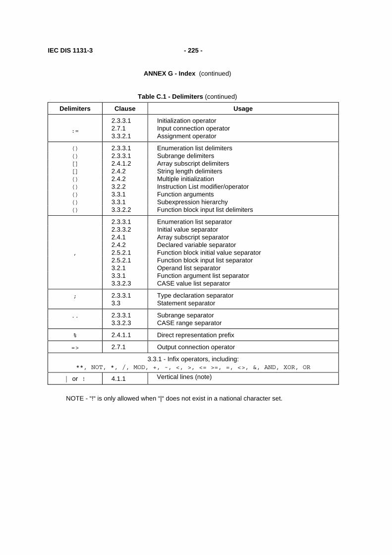
IEC DIS 1131-3 - 225 -
ANNEX G - Index (continued)
Table C.1 - Delimiters (continued)
Delimiters Clause Usage
:=
2.3.3.1 2.7.1 3.3.2.1
Initialization operator Input connection operator Assignment operator
() 2.3.3.1 Enumeration list delimiters () 2.3.3.1 Subrange delimiters [] 2.4.1.2 Array subscript delimiters [] 2.4.2 String length delimiters () 2.4.2 Multiple initialization () 3.2.2 Instruction List modifier/operator () 3.3.1 Function arguments () 3.3.1 Subexpression hierarchy () 3.3.2.2 Function block input list delimiters
2.3.3.1 Enumeration list separator 2.3.3.2 Initial value separator 2.4.1 Array subscript separator 2.4.2 Declared variable separator , 2.5.2.1 Function block initial value separator 2.5.2.1 Function block input list separator 3.2.1 Operand list separator 3.3.1 Function argument list separator 3.3.2.3 CASE value list separator
; 2.3.3.1 Type declaration separator 3.3 Statement separator
.. 2.3.3.1 Subrange separator 3.3.2.3 CASE range separator
% 2.4.1.1 Direct representation prefix
=> 2.7.1 Output connection operator
3.3.1 - Infix operators, including: **, NOT, *, /, MOD, +, -, <, >, <= >=, =, <>, &, AND, XOR, OR
| or ! 4.1.1 Vertical lines (note)
NOTE - “!“ is only allowed when “|“ does not exist in a national character set.

- 226 - IEC DIS 1131-3
ANNEX G - Index (continued)
Table C.2 - Keywords
Keywords Clause
ACTION...END_ACTION 2.6.4.1
ARRAY...OF 2.3.3.1
AT 2.4.3
CASE...OF...ELSE...END_CASE 3.3.2.3
CONFIGURATION...END_CONFIGURATION 2.7.1
CONSTANT 2.4.3
Data type names 2.3
EN, ENO 2.5.1.2
EXIT 3.3.2.4
FALSE 2.2.1
F_EDGE 2.5.2.2
FOR...TO...BY...DO...END_FOR 3.3.2.4
FUNCTION...END_FUNCTION 2.5.1.3
Function names 2.5.1
FUNCTION_BLOCK...END_FUNCTION_BLOCK 2.5.2.2
Function Block names 2.5.2
IF...THEN...ELSIF...ELSE...END_IF 3.3.2.3
INITIAL_STEP...END_STEP 2.6.2
PROGRAM...WITH... 2.7.1
PROGRAM...END_PROGRAM 2.5.3
(continued on following page)
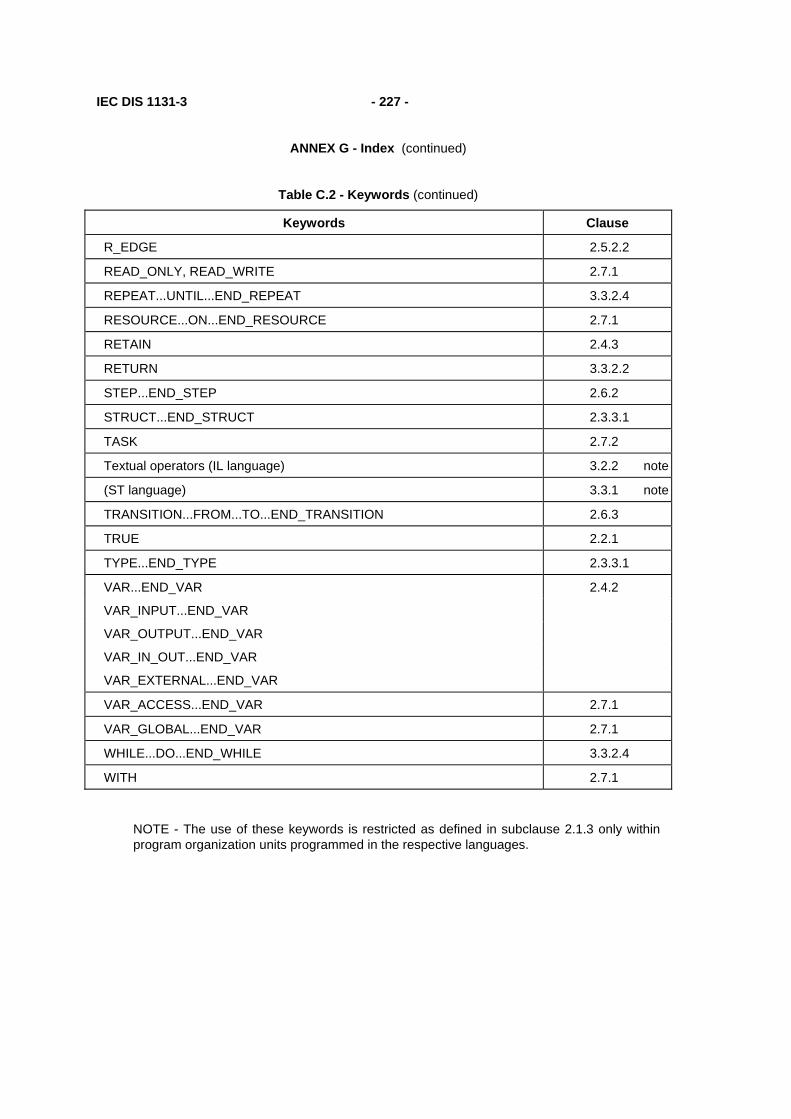
IEC DIS 1131-3 - 227 -
ANNEX G - Index (continued)
Table C.2 - Keywords (continued)
Keywords Clause
R_EDGE 2.5.2.2
READ_ONLY, READ_WRITE 2.7.1
REPEAT...UNTIL...END_REPEAT 3.3.2.4
RESOURCE...ON...END_RESOURCE 2.7.1
RETAIN 2.4.3
RETURN 3.3.2.2
STEP...END_STEP 2.6.2
STRUCT...END_STRUCT 2.3.3.1
TASK 2.7.2
Textual operators (IL language) 3.2.2 note
(ST language) 3.3.1 note
TRANSITION...FROM...TO...END_TRANSITION 2.6.3
TRUE 2.2.1
TYPE...END_TYPE 2.3.3.1
VAR...END_VAR 2.4.2
VAR_INPUT...END_VAR
VAR_OUTPUT...END_VAR
VAR_IN_OUT...END_VAR
VAR_EXTERNAL...END_VAR
VAR_ACCESS...END_VAR 2.7.1
VAR_GLOBAL...END_VAR 2.7.1
WHILE...DO...END_WHILE 3.3.2.4
WITH 2.7.1
NOTE - The use of these keywords is restricted as defined in subclause 2.1.3 only within program organization units programmed in the respective languages.

- 228 - IEC DIS 1131-3
ANNEX G - Index (continued)
ANNEX D - Implementation-dependent parameters (normative)
The implementation-dependent parameters defined in IEC 1131-3, and the primary reference clause for each, are listed in table D.1.
Table D.1 - Implementation-dependent parameters
Clause Parameters
1.5.1 Error handling procedures
2.1.1
National characters used # or „pounds Sterling“ sign $ or „currency“ sign | or !
2.1.2 Maximum length of identifiers
2.1.5 Maximum comment length
2.2.3.1 Range of values of duration
2.3.1 Range of values for variables of type TIME
Precision of representation of seconds in types TIME_OF_DAY and DATE_AND_TIME
2.3.3
Maximum number of array subscripts Maximum array size Maximum number of structure elements Maximum structure size Maximum number of variables per declaration
2.3.3.1 Maximum number of enumerated values
2.3.3.2 Default maximum length of STRING variables Maximum allowed length of STRING variables
2.4.1.1 Maximum number of hierarchical levels Logical or physical mapping
2.4.1.2 Maximum number of subscripts Maximum range of subscript values Maximum number of levels of structures
2.4.2 Initialization of system inputs
2.4.3 Maximum number of variables per declaration
2.5 Information to determine execution times of program organization units
2.5.1.1 Method of function representation (names or symbols)
2.5.1.3 Maximum number of function specifications
2.5.1.5 Maximum number of inputs of extensible functions
2.5.1.5.1 Effects of type conversions on accuracy
(continued on following page)
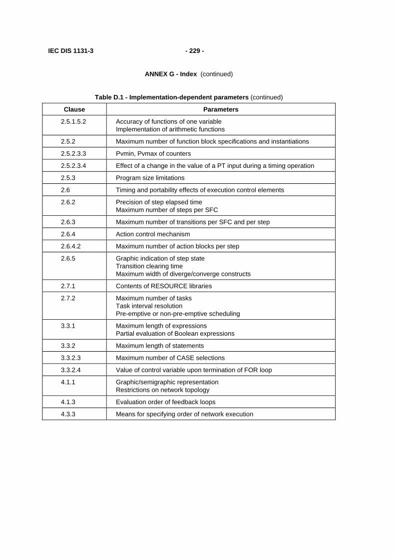
IEC DIS 1131-3 - 229 -
ANNEX G - Index (continued)
Table D.1 - Implementation-dependent parameters (continued)
Clause Parameters
2.5.1.5.2 Accuracy of functions of one variable Implementation of arithmetic functions
2.5.2 Maximum number of function block specifications and instantiations
2.5.2.3.3 Pvmin, Pvmax of counters
2.5.2.3.4 Effect of a change in the value of a PT input during a timing operation
2.5.3 Program size limitations
2.6 Timing and portability effects of execution control elements
2.6.2 Precision of step elapsed time Maximum number of steps per SFC
2.6.3 Maximum number of transitions per SFC and per step
2.6.4 Action control mechanism
2.6.4.2 Maximum number of action blocks per step
2.6.5 Graphic indication of step state Transition clearing time Maximum width of diverge/converge constructs
2.7.1 Contents of RESOURCE libraries
2.7.2 Maximum number of tasks Task interval resolution Pre-emptive or non-pre-emptive scheduling
3.3.1 Maximum length of expressions Partial evaluation of Boolean expressions
3.3.2 Maximum length of statements
3.3.2.3 Maximum number of CASE selections
3.3.2.4 Value of control variable upon termination of FOR loop
4.1.1 Graphic/semigraphic representation Restrictions on network topology
4.1.3 Evaluation order of feedback loops
4.3.3 Means for specifying order of network execution

- 230 - IEC DIS 1131-3
ANNEX G - Index (continued)
ANNEX E - Error Conditions (normative)
The error conditions defined in IEC 1131-3, and the primary reference clause for each, are listed in table E.1. These errors may be detected during preparation of the program for execution or during execution of the program. The manufacturer shall specify the disposition of these errors according to the provisions of subclause 1.5.1 of this part.
Table E.1 - Error conditions
Clause Error conditions
2.3.3.1 Value of a variable exceeds the specified subrange
2.4.2 Length of initialization list does not match number of array entries
2.5.1 Improper use of directly represented or external variables in functions
2.5.1.5.1 Type conversion errors
2.5.1.5.2 Numerical result exceeds range for data type Division by zero
2.5.1.5.4 Mixed input data types to a selection function Selector (K) out of range for MUX function
2.5.1.5.5 Invalid character position specified Result exceeds maximum string length
2.5.1.5.5 CONCAT result too long
2.5.1.5.6 Result exceeds range for data type
2.5.2.2 No parameter value specified for a function block instance used as input parameter
2.5.2.2 No parameter value specified for a VAR_IN_OUT parameter
2.6.2 Zero or more than one initial steps in SFC network User program attempts to modify step state or time
2.6.2.5 Simultaneously true, non-prioritized transitions in a selection divergence
2.6.3 Side effects in evaluation of transition condition
2.6.4.5 Action control contention error
2.6.5 Unsafe or unreachable SFC
2.7.1 Data type conflict in VAR_ACCESS
2.7.2 Tasks require too many processor resources Execution deadline not met Other task scheduling conflicts
3.2.2 Numerical result exceeds range for data type
3.2.2 Current result and operand not of same data type
3.3.1 Division by zero Invalid data type for operation
3.3.2.1 Return from function without value assigned
3.3.2.4 Iteration fails to terminate

IEC DIS 1131-3 - 231 -
ANNEX G - Index (continued)
4.1.1 Same identifier used as connector label and element name
4.1.3 Uninitialized feedback variable

- 232 - IEC DIS 1131-3
ANNEX G - Index (continued)

IEC DIS 1131-3 - 233 -
ANNEX G - Index (continued)
ANNEX F - Examples (informative)
F.1 Function WEIGH
Example function WEIGH provides the functions of BCD-to-binary conversion of a gross-weight input from a scale, the binary integer subtraction of a tare weight which has been previously converted and stored in the memory of the programmable controller, and the conversion of the resulting net weight back to BCD form, e.g., for an output display. The "EN" input is used to indicate that the scale is ready to perform the weighing operation.
The "ENO" output indicates that an appropriate command exists (e.g., from an operator pushbutton), the scale is in proper condition for the weight to be read, and each function has a correct result.
A textual form of the declaration of this function is:
FUNCTION WEIGH : WORD (* BCD encoded *)
VAR_INPUT (* "EN" input is used to indicate "scale ready" *) weigh_command : BOOL; gross_weight : WORD ; (* BCD encoded *) tare_weight : INT ; END_VAR
(* Function Body *)
END_FUNCTION (* Implicit "ENO" *)
The body of function WEIGH in the IL language is:
LD weigh_command JMPC WEIGH_NOW ST ENO (* No weighing, 0 to "ENO" *) RET WEIGH_NOW: LD gross_weight BCD_TO_INT SUB tare_weight INT_TO_BCD (* Return evaluated weight *)
The body of function WEIGH in the ST language is:
IF weigh_command THEN WEIGH := INT_TO_BCD (BCD_TO_INT(gross_weight) - tare_weight); END_IF ;
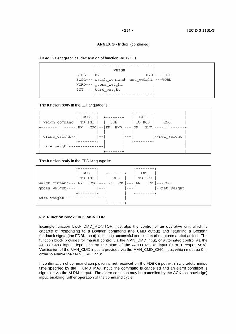
- 234 - IEC DIS 1131-3
ANNEX G - Index (continued)
An equivalent graphical declaration of function WEIGH is:
+-------------------------+ | WEIGH | BOOL---|EN ENO|---BOOL BOOL---|weigh_command net_weight|---WORD WORD---|gross_weight | INT----|tare_weight | +-------------------------+
The function body in the LD language is:
| +--------+ +--------+ | | | BCD_ | +-------+ | INT_ | | | weigh_command | TO_INT | | SUB | | TO_BCD | ENO | +-------| |-----|EN ENO|--|EN ENO|---|EN ENO|----( )------+ | | | | | | | | | gross_weight--| |--| |---| |--net_weight | | +--------+ | | +--------+ | | tare_weight---------------| | | | +-------+ |
The function body in the FBD language is:
+--------+ +--------+ | BCD_ | +-------+ | INT_ | | TO_INT | | SUB | | TO_BCD | weigh_command---|EN ENO|---|EN ENO|---|EN ENO|---ENO gross_weight----| |---| |---| |--net_weight +--------+ | | +--------+ tare_weight------------------| | +-------+
F.2 Function block CMD_MONITOR
Example function block CMD_MONITOR illustrates the control of an operative unit which is capable of responding to a Boolean command (the CMD output) and returning a Boolean feedback signal (the FDBK input) indicating successful completion of the commanded action. The function block provides for manual control via the MAN_CMD input, or automated control via the AUTO_CMD input, depending on the state of the AUTO_MODE input (0 or 1 respectively). Verification of the MAN_CMD input is provided via the MAN_CMD_CHK input, which must be 0 in order to enable the MAN_CMD input.
If confirmation of command completion is not received on the FDBK input within a predetermined time specified by the T_CMD_MAX input, the command is cancelled and an alarm condition is signalled via the ALRM output. The alarm condition may be cancelled by the ACK (acknowledge) input, enabling further operation of the command cycle.
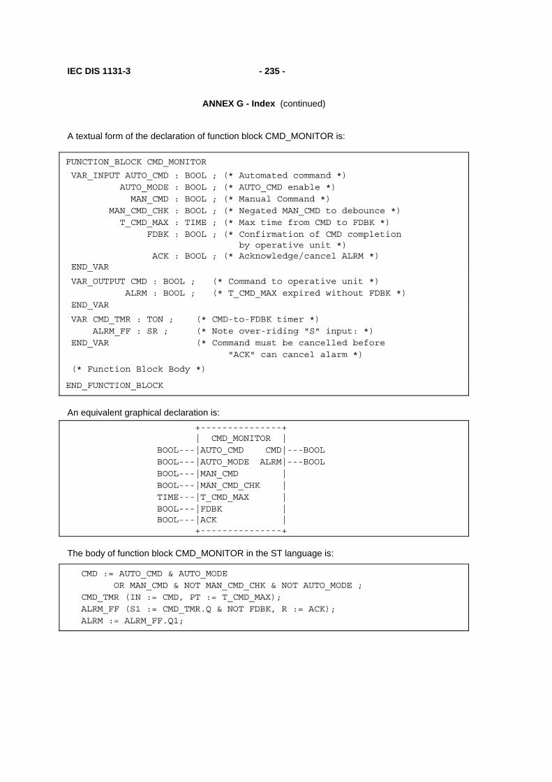
IEC DIS 1131-3 - 235 -
ANNEX G - Index (continued)
A textual form of the declaration of function block CMD_MONITOR is:
FUNCTION_BLOCK CMD_MONITOR
VAR_INPUT AUTO_CMD : BOOL ; (* Automated command *) AUTO_MODE : BOOL ; (* AUTO_CMD enable *) MAN_CMD : BOOL ; (* Manual Command *) MAN_CMD_CHK : BOOL ; (* Negated MAN_CMD to debounce *) T_CMD_MAX : TIME ; (* Max time from CMD to FDBK *) FDBK : BOOL ; (* Confirmation of CMD completion by operative unit *) ACK : BOOL ; (* Acknowledge/cancel ALRM *) END_VAR
VAR_OUTPUT CMD : BOOL ; (* Command to operative unit *) ALRM : BOOL ; (* T_CMD_MAX expired without FDBK *) END_VAR
VAR CMD_TMR : TON ; (* CMD-to-FDBK timer *) ALRM_FF : SR ; (* Note over-riding "S" input: *) END_VAR (* Command must be cancelled before "ACK" can cancel alarm *)
(* Function Block Body *)
END_FUNCTION_BLOCK
An equivalent graphical declaration is: +---------------+ | CMD_MONITOR | BOOL---|AUTO_CMD CMD|---BOOL BOOL---|AUTO_MODE ALRM|---BOOL BOOL---|MAN_CMD | BOOL---|MAN_CMD_CHK | TIME---|T_CMD_MAX | BOOL---|FDBK | BOOL---|ACK | +---------------+
The body of function block CMD_MONITOR in the ST language is:
CMD := AUTO_CMD & AUTO_MODE OR MAN_CMD & NOT MAN_CMD_CHK & NOT AUTO_MODE ; CMD_TMR (IN := CMD, PT := T_CMD_MAX); ALRM_FF (S1 := CMD_TMR.Q & NOT FDBK, R := ACK); ALRM := ALRM_FF.Q1;

- 236 - IEC DIS 1131-3
ANNEX G - Index (continued)
The body of function block CMD_MONITOR in the IL language is:
LD T_CMD_MAX ST CMD_TMR.PT (* Store an input to the TON FB *) LD AUTO_CMD AND AUTO_MODE OR( MAN_CMD ANDN
AUTO_MODE
ANDN
MAN_CMD_CHK
) ST CMD IN CMD_TMR (* Invoke the TON FB *) LD CMD_TMR.Q ANDN
FDBK
ST ALRM_FF.S1 (* Store an input to the SR FB *) LD ACK R ALRM_FF (* Invoke the SR FB *) LD ALRM_FF.Q1 ST ALRM
The body of function block CMD_MONITOR in the LD language is:
| | | AUTO_MODE AUTO_CMD CMD | +--| |--------| |-------------------+---( )--+ | | | | AUTO_MODE MAN_CMD MAN_CMD_CHECK | | +--|/|-------| |------|/|-----------+ | | | | ACK ALRM | +--| |---------------------------------(R)---+ | CMD_TMR | | +-----+ | | CMD | TON | FDBK ALRM | +--| |-------|IN Q|------|/|----------(S)---+ | T_CMD_MAX--|PT ET| | | +-----+ | | |

IEC DIS 1131-3 - 237 -
ANNEX G - Index (continued)
The body of function block CMD_MONITOR in the FBD language is:
+-+ +---+ AUTO_CMD------|&|----|>=1|--+-------------------------------CMD AUTO_MODE--+--| | +--| | | | +-+ | +---+ | | | | | +-+ | | CMD_TMR ALRM_FF +-O|&| | | +-----+ +-----+ MAN_CMD-------| |-+ | | TON | +-+ | SR | MAN_CMD_CHK--O| | +--|IN Q|------|&|----|S1 Q1|--ALRM +-+ | | +--O| | +--|R | T_CMD_MAX----------------------|PT ET| | +-+ | +-----+ +-----+ | | FDBK------------------------------------+ | ACK---------------------------------------------+
F.3 Function block FWD_REV_MON
Example function block FWD_REV_MON illustrates the control of an operative unit capable of two-way positioning action, e.g., a motor-operated valve. Both automated and manual control modes are possible, with alarm capabilities provided for each direction of motion, as described for function block CMD_MONITOR above. In addition, contention between forward and reverse commands causes the cancellation of both commands and signalling of an alarm condition. The Boolean OR of all alarm conditions is made available as a KLAXON output for operator signaling.
A graphical declaration of this function block is:
+----------------------+ | FWD_REV_MON | BOOL---|AUTO KLAXON|---BOOL BOOL---|ACK FWD_REV_ALRM|---BOOL BOOL---|AUTO_FWD FWD_CMD|---BOOL BOOL---|MAN_FWD FWD_ALRM|---BOOL BOOL---|MAN_FWD_CHK | TIME---|T_FWD_MAX | BOOL---|FWD_FDBK | BOOL---|AUTO_REV REV_CMD|---BOOL BOOL---|MAN_REV REV_ALRM|---BOOL BOOL---|MAN_REV_CHK | TIME---|T_REV_MAX | BOOL---|REV_FDBK | +----------------------+

- 238 - IEC DIS 1131-3
ANNEX G - Index (continued)
A textual form of the declaration of function block FWD_REV_MON is:
FUNCTION_BLOCK FWD_REV_MON
VAR_INPUT AUTO : BOOL ;(* Enable automated commands *) ACK : BOOL ; (* Acknowledge/cancel all alarms *) AUTO_FWD : BOOL ; (* Automated forward command *) MAN_FWD : BOOL ; (* Manual forward command *) MAN_FWD_CHK : BOOL ; (* Negated MAN_FWD for debouncing *) T_FWD_MAX : TIME ; (* Maximum time from FWD_CMD to FWD_FDBK *) FWD_FDBK : BOOL ; (* Confirmation of FWD_CMD completion *) (* by operative unit *) AUTO_REV : BOOL ; (* Automated reverse command *) MAN_REV : BOOL ; (* Manual reverse command *) MAN_REV_CHK : BOOL ; (* Negated MAN_REV for debouncing *) T_REV_MAX : TIME ; (* Maximum time from REV_CMD to REV_FDBK *) REV_FDBK : BOOL ; (* Confirmation of REV_CMD completion *) END_VAR (* by operative unit *)
VAR_OUTPUT KLAXON : BOOL ; (* Any alarm active *) FWD_REV_ALRM : BOOL; (* Forward/reverse command conflict *) FWD_CMD : BOOL ; (* "Forward" command to operative unit *) FWD_ALRM : BOOL ; (* T_FWD_MAX expired without FWD_FDBK *) REV_CMD : BOOL ; (* "Reverse" command to operative unit *) REV_ALRM : BOOL ; (* T_REV_MAX expired without REV_FDBK *) END_VAR
VAR FWD_MON : CMD_MONITOR; (* "Forward" command monitor *) REV_MON : CMD_MONITOR; (* "Reverse" command monitor *) FWD_REV_FF : SR ; (* Forward/Reverse contention latch *) END_VAR
(* Function Block body *)
END_FUNCTION_BLOCK

IEC DIS 1131-3 - 239 -
ANNEX G - Index (continued)
The body of function block FWD_REV_MON can be written in the ST language as:
(* Evaluate internal function blocks *)
FWD_MON (AUTO_MODE := AUTO, ACK := ACK, AUTO_CMD := AUTO_FWD, MAN_CMD := MAN_FWD, MAN_CMD_CHK := MAN_FWD_CHK, T_CMD_MAX := T_FWD_MAX, FDBK := FWD_FDBK); REV_MON (AUTO_MODE := AUTO, ACK := ACK, AUTO_CMD := AUTO_REV, MAN_CMD := MAN_REV, MAN_CMD_CHK := MAN_REV_CHK, T_CMD_MAX := T_REV_MAX, FDBK := REV_FDBK); FWD_REV_FF (S1 := FWD_MON.CMD & REV_MON.CMD, R := ACK);
(* Transfer data to outputs *)
FWD_REV_ALRM := FWD_REV_FF.Q1; FWD_CMD := FWD_MON.CMD & NOT FWD_REV_ALRM; FWD_ALRM := FWD_MON.ALRM; REV_CMD := REV_MON.CMD & NOT FWD_REV_ALRM; REV_ALRM := REV_MON.ALRM; KLAXON := FWD_ALRM OR REV_ALRM OR FWD_REV_ALRM;

- 240 - IEC DIS 1131-3
ANNEX G - Index (continued)
The body of function block FWD_REV_MON in the IL language is:
LD AUTO (* Load common inputs *) ST FWD_MON.AUTO_MODE ST REV_MON.AUTO_MODE LD ACK ST FWD_MON.ACK ST REV_MON.ACK ST FWD_REV_FF.R LD AUTO_FWD (* Load inputs to FWD_MON *) ST FWD_MON.AUTO_CMD LD MAN_FWD ST FWD_MON.MAN_CMD LD MAN_FWD_CHK ST FWD_MON.MAN_CMD_CHK LD T_FWD_MAX ST FWD_MON.T_CMD_MAX LD FWD_FDBK ST FWD_MON.FDBK CAL FWD_MON (* Activate FWD_MON *) LD AUTO_REV (* Load inputs to REV_MON *) ST REV_MON.AUTO_CMD LD MAN_REV ST REV_MON.MAN_CMD LD MAN_REV_CHK ST REV_MON.MAN_CMD_CHK LD T_REV_MAX ST REV_MON.T_CMD_MAX LD REV_FDBK ST REV_MON.FDBK CAL REV_MON (* Activate REV_MON *) LD FWD_MON.CMD (* Check for contention *) AND REV_MON.CMD S1 FWD_REV_FF (* Latch contention condition *) LD FWD_REV_FF.Q ST FWD_REV_ALRM (* Contention alarm *) LD FWD_MON.CMD (* "Forward" command and alarm *) ANDN FWD_REV_ALRM ST FWD_CMD LD FWD_MON.ALRM ST FWD_ALRM LD REV_MON.CMD (* "Reverse" command and alarm *) ANDN FWD_REV_ALRM ST REV_CMD LD REV_MON.ALRM ST REV_ALRM OR FWD_ALRM (* OR all alarms *) OR FWD_REV_ALRM ST KLAXON

IEC DIS 1131-3 - 241 -
ANNEX G - Index (continued)
The body of function block FWD_REV_MON in the FBD language is:
FWD_MON +---------------+ | CMD_MONITOR | AUTO_FWD----------|AUTO_CMD CMD|--+ AUTO---------+----|AUTO_MODE ALRM|--|-------FWD_ALRM MAN_FWD------|----|MAN_CMD | | MAN_FWD_CHK--|----|MAN_CMD_CHK | | FWD_FDBK-----|----|FDBK | | ACK----------|-+--|ACK | | T_FWD_MAX----|-|--|T_CMD_MAX | | +---+ | | +---------------+ +--| & |-------------+ | | +--| | | | | REV_MON | +---+ | | | +---------------+ | | | | | CMD_MONITOR | | | AUTO_REV-----|-|--|AUTO_CMD CMD|--+ | +-|--|AUTO_MODE ALRM|---------REV_ALRM | MAN_REV--------|--|MAN_CMD | | MAN_REV_CHK----|--|MAN_CMD_CHK | | REV_FDBK-------|--|FDBK | | +--|ACK | | T_REV_MAX---------|T_CMD_MAX | | +---------------+ | +------------------------------------------------+ | FWD_REV_FF | +------+ | | SR | +-----|S1 Q1|--+----------------FWD_REV_ALRM ACK---|R | | +------+ | +-----+ +---| >=1 |------KLAXON FWD_MON.ALRM-------------|---| | REV_MON.ALRM-------------|---| | | +-----+ | | +---+ +--O| & |--------FWD_CMD FWD_MON.CMD--------------|---| | | +---+ | | +---+ +--O| & |--------REV_CMD REV_MON.CMD------------------| | +---+
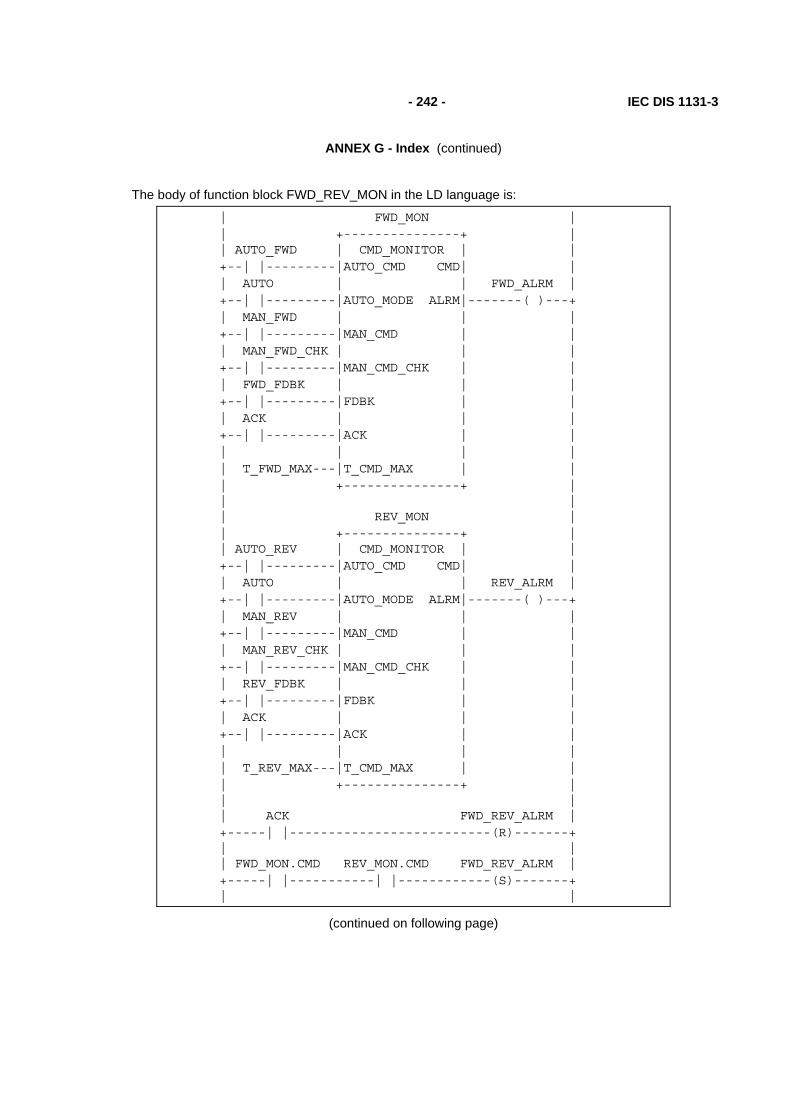
- 242 - IEC DIS 1131-3
ANNEX G - Index (continued)
The body of function block FWD_REV_MON in the LD language is:
| FWD_MON | | +---------------+ | | AUTO_FWD | CMD_MONITOR | | +--| |---------|AUTO_CMD CMD| | | AUTO | | FWD_ALRM | +--| |---------|AUTO_MODE ALRM|-------( )---+ | MAN_FWD | | | +--| |---------|MAN_CMD | | | MAN_FWD_CHK | | | +--| |---------|MAN_CMD_CHK | | | FWD_FDBK | | | +--| |---------|FDBK | | | ACK | | | +--| |---------|ACK | | | | | | | T_FWD_MAX---|T_CMD_MAX | | | +---------------+ | | | | REV_MON | | +---------------+ | | AUTO_REV | CMD_MONITOR | | +--| |---------|AUTO_CMD CMD| | | AUTO | | REV_ALRM | +--| |---------|AUTO_MODE ALRM|-------( )---+ | MAN_REV | | | +--| |---------|MAN_CMD | | | MAN_REV_CHK | | | +--| |---------|MAN_CMD_CHK | | | REV_FDBK | | | +--| |---------|FDBK | | | ACK | | | +--| |---------|ACK | | | | | | | T_REV_MAX---|T_CMD_MAX | | | +---------------+ | | | | ACK FWD_REV_ALRM | +-----| |--------------------------(R)-------+ | | | FWD_MON.CMD REV_MON.CMD FWD_REV_ALRM | +-----| |-----------| |------------(S)-------+ | |
(continued on following page)

IEC DIS 1131-3 - 243 -
ANNEX G - Index (continued)
(FWD_REV_MON function block body - LD language - continued)
| | | FWD_MON.CMD FWD_REV_ALRM FWD_CMD | +-----| |-----------|/|-------------( )------+ | | | REV_MON.CMD FWD_REV_ALRM REV_CMD | +-----| |-----------|/|-------------( )------+ | | | FWD_REV_ALRM KLAXON | +-----| |------+--------------------( )------+ | | | | FWD_ALRM | | +-----| |------+ | | | | | REV_ALRM | | +-----| |------+ | | |
F.4 Function block STACK_INT
This function block provides a stack of up to 128 integers. The usual stack operations of PUSH and POP are provided by edge-triggered Boolean inputs. An overriding reset (R1) input is provided; the maximum stack depth (N) is determined at the time of resetting. In addition to the top-of-stack data (OUT), Boolean outputs are provided indicating stack empty and stack overflow states.
A textual form of the declaration of this function block is:
FUNCTION_BLOCK STACK_INT VAR_INPUT PUSH, POP: BOOL R_EDGE; (* Basic stack operations *) R1 : BOOL ; (* Over-riding reset *) IN : INT ; (* Input to be pushed *) N : INT ; (* Maximum depth after reset *) END_VAR VAR_OUTPUT EMPTY : BOOL := 1 ; (* Stack empty *) OFLO : BOOL := 0 ; (* Stack overflow *) OUT : INT := 0 ; (* Top of stack data *) END_VAR VAR STK : ARRAY[0..127] OF INT; (* Internal stack *) NI : INT :=128 ; (* Storage for N upon reset *) PTR : INT := -1 ; (* Stack pointer *) END_VAR
(* Function Block body *)
END_FUNCTION_BLOCK

- 244 - IEC DIS 1131-3
ANNEX G - Index (continued)
A graphical declaration of function block STACK_INT is:
+-----------+ | STACK_INT | BOOL--->PUSH EMPTY|---BOOL BOOL--->POP OFLO|---BOOL BOOL---|R1 OUT|---INT INT----|IN | INT----|N | +-----------+
(* Internal variable declarations *)
VAR STK : ARRAY[0..127] OF INT ; (* Internal Stack *) NI : INT :=128 ; (* Storage for N upon Reset *) PTR : INT := -1 ; (* Stack Pointer *) END_VAR
The function block body in the ST language is:
IF R1 THEN OFLO := 0; EMPTY := 1; PTR := -1; NI := LIMIT (MN:=1,IN:=N,MX:=128); OUT := 0; ELSIF POP & NOT EMPTY THEN OFLO := 0; PTR := PTR-1; EMPTY := PTR < 0; IF EMPTY THEN OUT := 0; ELSE OUT := STK[PTR]; END_IF ; ELSIF PUSH & NOT OFLO THEN EMPTY := 0; PTR := PTR+1; OFLO := (PTR = NI); IF NOT OFLO THEN OUT := IN ; STK[PTR] := IN; ELSE OUT := 0; END_IF ; END_IF ;
The function block body in the LD language is:
| | | R1 | +---| |--->>RESET | | | | POP EMPTY | +--| |---|/|--->>POP_STK | | | | PUSH OFLO | +--| |---|/|--->>PUSH_STK | | | | | +--------------<RETURN> |
(continued on following page)

IEC DIS 1131-3 - 245 -
ANNEX G - Index (continued)
(STACK_INT function block body - LD language - continued)
RESET: | +--------+ +-------+ | | | MOVE | | LIMIT | OFLO | +------|EN ENO|------------|EN ENO|--+---(R)---+ | 0---| |--OUT 128--|MX | | EMPTY | | -1 --| |--PTR N--|IN | +---(S)---+ | +--------+ 1--|MN |--NI | | +-------+ |
POP_STK: | +--------+ +--------+ | | | SUB | | LT | | +------------|EN ENO|-------|EN ENO| EMPTY | | PTR--| |--PTR--| |----(S)---+ | 1--| | 0--| | | | +--------+ +--------+ | | | | +-------+ | | | SEL | OFLO | +------------------|EN ENO|---------------(R)----+ | EMPTY | | | +---| |------------|G |---OUT | | STK[PTR]---|IN0 | | | 0 ---|IN1 | | | +-------+ | +--------------------------------<RETURN> |
PUSH_STK: | | | +--------+ +--------+ | | | ADD | | EQ | | +------------|EN ENO|-------|EN ENO| OFLO | | PTR--| |--PTR--| |----(S)---+ | 1--| | NI--| | | | +--------+ +--------+ | | | | +------+ | | OFLO | MOVE | | +---|/|-------|EN ENO|----------------------------+ | IN---| |---STK[PTR] | | +------+ | | | | +-------+ | | | SEL | EMPTY | +-------------|EN ENO|--------------------(R)----+ | OFLO | | | +---| |-------|G |---OUT | | IN---|IN0 | | | 0 ---|IN1 | | | +-------+ |

- 246 - IEC DIS 1131-3
ANNEX G - Index (continued)
The body of function block STACK_INT in the IL language is:
LD R1 (* Dispatch on operations *) JMPC RESET LD POP ANDN EMPTY (* Don't pop empty stack *) JMPC POP_STK LD PUSH ANDN OFLO (* Don't push overflowed stack *) JMPC PUSH_STK RET (* Return if no operations active *) RESET: LD 0 (* Stack reset operations *) ST OFLO LD 1 ST EMPTY LD -1 ST PTR CAL LIMIT(MN:=1,IN:=N,MX:=128) ST NI JMP ZRO_OUT POP_STK: LD 0 ST OFLO (* Popped stack is not overflowing *) LD PTR SUB 1 ST PTR LT 0 (* Empty when PTR < 0 *) ST EMPTY JMPC ZRO_OUT LD STK[PTR] JMP SET_OUT PUSH_STK: LD 0 ST EMPTY (* Pushed stack is not empty *) LD PTR ADD 1 ST PTR EQ NI (* Overflow when PTR = NI *) ST OFLO JMPC ZRO_OUT LD IN ST STK[PTR] (* Push IN onto STK *) JMP SET_OUT ZRO_OUT: LD 0 (* OUT=0 for EMPTY or OFLO *) SET_OUT: ST OUT

IEC DIS 1131-3 - 247 -
ANNEX G - Index (continued)
The body of function block STACK_INT in the FBD language is:
R1--+-->>RESET | +-+ +-----------------------------O|&|--<RETURN> | +-+ +--------------------O| | +--O|&| | +--O| | POP-----| |--+-->>POP_STK | +-+ EMPTY--O| | | +-+ | +-+ +-----------O|&|--+-->>PUSH_STK R1-----------------------O| | PUSH----------------------| | OFLO---------------------O| | +-+
RESET: +------+ +-------+ | := | | LIMIT | 1 --|EN ENO|---------------|EN ENO|--<RETURN> 0 --| |---OUT 128--|MX | -1 --| |---PTR N--|IN |--NI 0 --| |---OFLO 1--|MN | 1 --| |---EMPTY +-------+ +------+
POP_STK: +-----+ +---+ +---+ | SEL | +----+ PTR --| - |--PTR--| < |--EMPTY--|G |------| := |--OUT 1 --| | 0 --| | | | 0 --| |--OFLO +---+ +---+ | | 1 --| |--<RETURN> STK[PTR]--|IN0 | +----+ 0 ---|IN1 | +-----+
PUSH_STK: +------+ +---+ +---+ | := | PTR --| + |--PTR--| = |--+--OFLO---O|EN ENO| 1 --| | NI--| | | | | +---+ +---+ | 0 ---| |--EMPTY | IN---| |--+--STK[PTR] | +------+ | | +------+ +--OUT | | := | +--| |---EMPTY 0 ---| |---OUT +------+

- 248 - IEC DIS 1131-3
ANNEX G - Index (continued)
F.5 Function block MIX_2_BRIX
Function block MIX_2_BRIX is to control the mixing of two bricks of solid material, brought one at a time on a belt, with weighed quantities of two liquid components, A and B, as shown in figure F.1. A "Start" (ST) command, which may be manual or automatic, initiates a measurement and mixing cycle beginning with simultaneous weighing and brick transport as follows:
- Liquid A is weighed up to mark "a" of the weighing unit, then liquid B is weighed up to mark "b", followed by filling of the mixer from weighing unit C;
- Two bricks are transported by belt into the mixer.
The cycle ends with the mixer rotating and finally tipping after a predetermined time "t1". Rotation of the mixer continues while it is emptying.
The scale reading "WC" is given as four BCD digits, and will be converted to type INT for internal operations. It is assumed that the tare (empty weight) "z" has been previously determined.
MR
A
VA
B
VB
C
VC||| a ||||| b |||WC
MP0
MP1
S0
S1
MT
dtransit detector
belt motor
bricks
feed belt
tipping mixer
mixing motor
bidirectionaltipping motor
"Down" limit switch
"Up" limit switch
Weighing unit
Figure F.1 - Function block MIX_2_BRIX - Physical model

IEC DIS 1131-3 - 249 -
ANNEX G - Index (continued)
The textual form of the declaration of this function block is:
FUNCTION_BLOCK MIX_2_BRIX VAR_INPUT ST : BOOL ; (* "Start" command *) d : BOOL ; (* Transit detector *) S0 : BOOL ; (* "Mixer up" limit switch *) S1 : BOOL ; (* "Mixer down" limit switch *) WC : WORD; (* Current scale reading in BCD *) z : INT ; (* Tare (empty) weight *) WA : INT ; (* Desired weight of A *) WB : INT ; (* Desired weight of B *) t1 : TIME ; (* Mixing time *) END_VAR
VAR_OUTPUT DONE , VA , (* Valve "A" : 0 - close, 1 - open *) VB , (* Valve "B" : 0 - close, 1 - open *) VC , (* Valve "C" : 0 - close, 1 - open *) MT , (* Feed belt motor *) MR , (* Mixer rotation motor *) MP0 , (* Tipping motor "up" command *) MP1 : BOOL; (* Tipping motor "down" command *) END_VAR
(* Function block body *)
END_FUNCTION_BLOCK
A graphical declaration is:
+------------+ | MIX_2_BRIX | BOOL---|ST DONE|---BOOL BOOL---|d VA|---BOOL BOOL---|S0 VB|---BOOL BOOL---|S1 VC|---BOOL WORD---|WC MT|---BOOL INT---|z MR|---BOOL INT---|WA MP0|---BOOL INT---|WB MP1|---BOOL TIME---|t1 | +------------+

- 250 - IEC DIS 1131-3
ANNEX G - Index (continued)
The body of function block MIX_2_BRIX using graphical SFC elements with transition conditions in the ST language is:

IEC DIS 1131-3 - 251 -
ANNEX G - Index (continued)
+----------->------------+ | | | +====+====+ +---+------+ | || START ||---| N | DONE | | +====+====+ +---+------+ | | | + ST & S0 & BCD_TO_INT(WC) <= z | | | ===+===============+================+======= | | | | +----+----+ +---+----+ +----+---+ +---+----+ | | WEIGH_A |---| N | VA | | BRICK1 |---| S | MT | | +----+----+ +---+----+ +----+---+ +---+----+ | | | | + BCD_TO_INT(WC) >= WA+z + d | | | | +----+----+ +---+----+ +----+---+ | | WEIGH_B |---| N | VB | | DROP_1 | | +----+----+ +---+----+ +----+---+ | | | | + BCD_TO_INT(WC) >= WA+WB+z + NOT d | | | | +----+----+ +---+----+ +----+---+ | | FILL |---| N | VC | | BRICK2 | | +----+----+ +---+----+ +----+---+ | | + d | | +----+---+ +---+----+ | | | DROP_2 |---| R | MT | | | +----+---+ +---+----+ | | | | ====+===============+================+===== | | | + BCD_TO_INT(WC) <= z & NOT d | | | +--+--+ +---+----+ | | MIX |---| S | MR | | +--+--+ +---+----+ | | | + MIX.T >= t1 | | | +--+--+ +---+-----+----+ | | TIP |---| N | MP1 | S1 | | +--+--+ +---+-----+----+ | | | + S1 | | | +---+---+ +---+-----+----+ | | RAISE |---| R | MR | | | +---+---+ +---+-----+----+ | +S0 | N | MP0 | S0 | | | +---+-----+----+ +-----------<------------+

- 252 - IEC DIS 1131-3
ANNEX G - Index (continued)
The body of function block MIX_2_BRIX in a textual SFC representation using ST language elements is:
INITIAL_STEP START: DONE(N); END_STEP
TRANSITION FROM START TO (WEIGH_A, BRICK1) := ST & S0 & BCD_TO_INT(WC) <= z; END_TRANSITION
STEP WEIGH_A: VA(N); END_STEP
TRANSITION FROM WEIGH_A TO WEIGH_B := BCD_TO_INT(WC) >= WA+z ; END_TRANSITION
STEP WEIGH_B: VB(N); END_STEP
TRANSITION FROM WEIGH_B TO FILL := BCD_TO_INT(WC) >= WA+WB+z ; END_TRANSITION
STEP FILL: VC(N); END_STEP
STEP BRICK1: MT(S); END_STEP
TRANSITION FROM BRICK1 TO DROP_1 := d ; END_TRANSITION
STEP DROP_1: END_STEP
TRANSITION FROM DROP_1 TO BRICK2 := NOT d ; END_TRANSITION
STEP BRICK2: END_STEP
TRANSITION FROM BRICK2 TO DROP_2 := d ; END_TRANSITION
STEP DROP_1: MT(R); END_STEP
TRANSITION FROM (FILL,DROP_2) TO MIX := BCD_TO_INT(WC) <= z & NOT d ; END_TRANSITION
STEP MIX: MR(S); END_STEP
TRANSITION FROM MIX TO TIP := MIX.T >= t1 ; END_TRANSITION
STEP TIP: MP1(N); END_STEP
TRANSITION FROM TIP TO RAISE := S1 ; END_TRANSITION
STEP RAISE: MR(R); MP0(N); END_STEP
TRANSITION FROM RAISE TO START := S0 ; END_TRANSITION
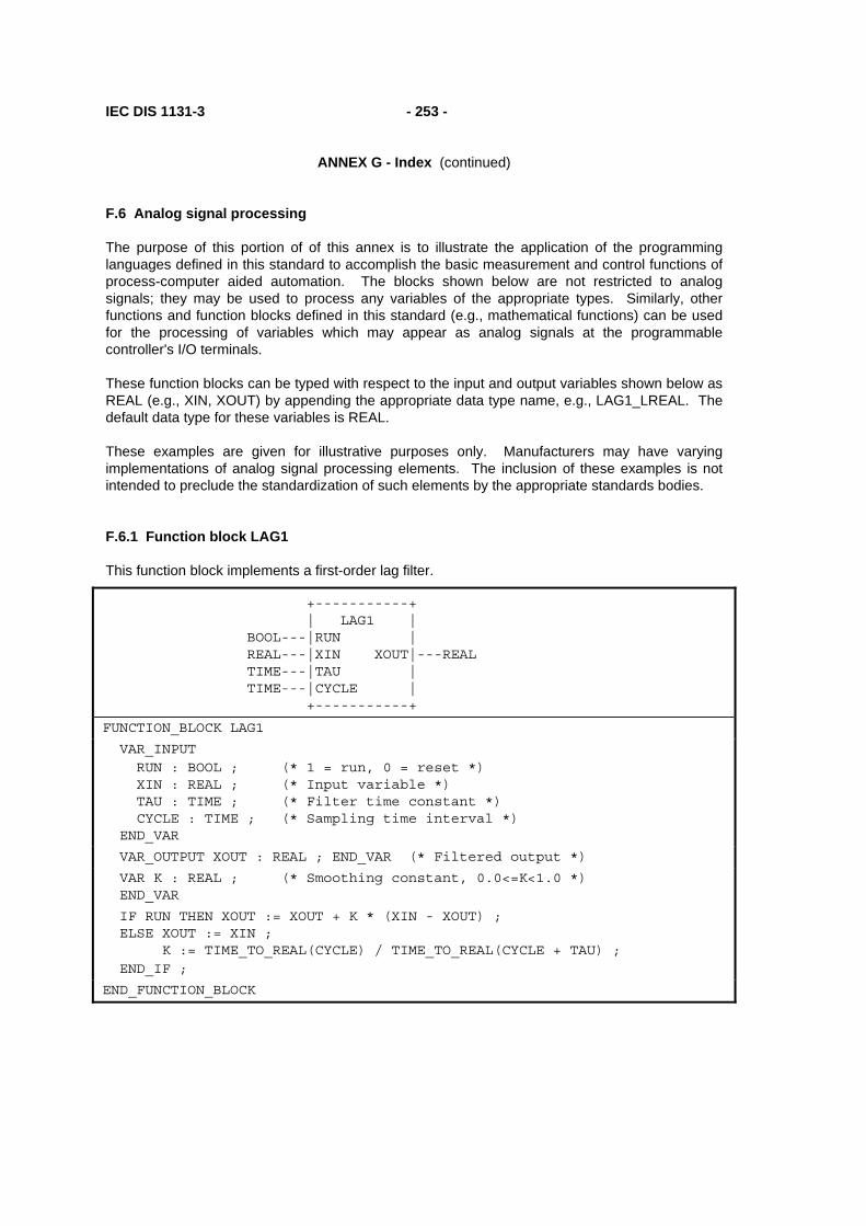
IEC DIS 1131-3 - 253 -
ANNEX G - Index (continued)
F.6 Analog signal processing
The purpose of this portion of of this annex is to illustrate the application of the programming languages defined in this standard to accomplish the basic measurement and control functions of process-computer aided automation. The blocks shown below are not restricted to analog signals; they may be used to process any variables of the appropriate types. Similarly, other functions and function blocks defined in this standard (e.g., mathematical functions) can be used for the processing of variables which may appear as analog signals at the programmable controller's I/O terminals.
These function blocks can be typed with respect to the input and output variables shown below as REAL (e.g., XIN, XOUT) by appending the appropriate data type name, e.g., LAG1_LREAL. The default data type for these variables is REAL.
These examples are given for illustrative purposes only. Manufacturers may have varying implementations of analog signal processing elements. The inclusion of these examples is not intended to preclude the standardization of such elements by the appropriate standards bodies.
F.6.1 Function block LAG1
This function block implements a first-order lag filter.
+-----------+ | LAG1 | BOOL---|RUN | REAL---|XIN XOUT|---REAL TIME---|TAU | TIME---|CYCLE | +-----------+
FUNCTION_BLOCK LAG1
VAR_INPUT RUN : BOOL ; (* 1 = run, 0 = reset *) XIN : REAL ; (* Input variable *) TAU : TIME ; (* Filter time constant *) CYCLE : TIME ; (* Sampling time interval *) END_VAR
VAR_OUTPUT XOUT : REAL ; END_VAR (* Filtered output *)
VAR K : REAL ; (* Smoothing constant, 0.0<=K<1.0 *) END_VAR
IF RUN THEN XOUT := XOUT + K * (XIN - XOUT) ; ELSE XOUT := XIN ; K := TIME_TO_REAL(CYCLE) / TIME_TO_REAL(CYCLE + TAU) ; END_IF ;
END_FUNCTION_BLOCK

- 254 - IEC DIS 1131-3
ANNEX G - Index (continued)
F.6.2 Function block DELAY
This function block implements an N-sample delay.
+-----------+ | DELAY | BOOL---|RUN | REAL---|XIN XOUT|---REAL INT----|N | +-----------+
FUNCTION_BLOCK DELAY (* N-sample delay *)
VAR_INPUT RUN : BOOL ; (* 1 = run, 0 = reset *) XIN : REAL ; N : INT (* 0 <= N < 128 or manufacturer- *) END_VAR (* specified maximum value *)
VAR_OUTPUT XOUT : REAL; END_VAR (* Delayed output *)
VAR X : ARRAY [0..127] (* N-Element queue *) OF REAL; (* with FIFO discipline *) I, IXIN, IXOUT : INT := 0; END_VAR
IF RUN THEN IXIN := MOD(IXIN + 1, 128) ; X[IXIN] := XIN ; IXOUT := MOD(IXOUT + 1, 128) ; XOUT := X[IXOUT]; ELSE XOUT := XIN ; IXIN := N ; IXOUT := 0; FOR I := 0 TO N DO X[I] := XIN; END_FOR; END_IF ; END_FUNCTION_BLOCK

IEC DIS 1131-3 - 255 -
ANNEX G - Index (continued)
F.6.3 Function block AVERAGE
This function block implements a running average over N samples.
+-----------+ | AVERAGE | BOOL---|RUN | REAL---|XIN XOUT|---REAL INT----|N | +-----------+
FUNCTION_BLOCK AVERAGE
VAR_INPUT EN : BOOL ; (* 1 = run, 0 = reset *) XIN : REAL ; (* Input variable *) N : INT ; (* 0 <= N < 128 or manufacturer- *) END_VAR (* specified maximum value *)
VAR_OUTPUT XOUT : REAL ; END_VAR (* Averaged output *)
VAR SUM : REAL := 0.0; (* Running sum *) FIFO : DELAY ; (* N-Element FIFO *) END_VAR
SUM := SUM - FIFO.XOUT ; FIFO (RUN := RUN , XIN := XIN, N := N) ; SUM := SUM + FIFO.XOUT ; IF RUN THEN XOUT := SUM/N ; ELSE SUM := N*XIN ; XOUT := XIN ; END_IF ;
END_FUNCTION_BLOCK

- 256 - IEC DIS 1131-3
ANNEX G - Index (continued)
F.6.4 Function block INTEGRAL
This function block implements integration over time.
+-----------+ | INTEGRAL | BOOL---|RUN Q|---BOOL BOOL---|R1 | REAL---|XIN XOUT|---REAL REAL---|X0 | TIME---|CYCLE | +-----------+
FUNCTION_BLOCK INTEGRAL
VAR_INPUT RUN : BOOL ; (* 1 = integrate, 0 = hold *) R1 : BOOL ; (* Overriding reset *) XIN : REAL ; (* Input variable *) X0 : REAL ; (* Initial value *) CYCLE : TIME ; (* Sampling period *) END_VAR
VAR_OUTPUT Q : BOOL ; (* NOT R1 *) XOUT : REAL ; (* Integrated output *) END_VAR
Q := NOT R1 ; IF R1 THEN XOUT := X0 ; ELSIF RUN THEN XOUT := XOUT + XIN * TIME_TO_REAL(CYCLE); END_IF ;
END_FUNCTION_BLOCK

IEC DIS 1131-3 - 257 -
ANNEX G - Index (continued)
F.6.5 Function block DERIVATIVE
This function block implements differentiation with respect to time.
+------------+ | DERIVATIVE | BOOL---|RUN | REAL---|XIN XOUT|---REAL TIME---|CYCLE | +------------+
FUNCTION_BLOCK DERIVATIVE
VAR_INPUT RUN : BOOL ; (* 0 = reset *) XIN : REAL ; (* Input to be differentiated *) CYCLE : TIME ; (* Sampling period *) END_VAR
VAR_OUTPUT XOUT : REAL ; (* Differentiated output *) END_VAR
VAR X1, X2, X3 : REAL ; END_VAR
IF RUN THEN XOUT := (3.0 * (XIN - X3) + X1 - X2) / (10.0 * TIME_TO_REAL(CYCLE)) ; X3 := X2 ; X2 := X1 ; X1 := XIN ; ELSE XOUT := 0.0; X1 := XIN ; X2 := XIN ; X3 := XIN ; END_IF ;
END_FUNCTION_BLOCK
F.6.6 Function block HYSTERESIS
This function block implements Boolean hysteresis on the difference of REAL inputs.
+------------+ | HYSTERESIS | REAL---|XIN1 Q|---BOOL REAL---|XIN2 | REAL---|EPS | +------------+
FUNCTION_BLOCK HYSTERESIS (* Boolean hysteresis on difference *) (* of REAL inputs, XIN1 - XIN2 *)
VAR_INPUT XIN1, XIN2, EPS : REAL; END_VAR
VAR_OUTPUT Q : BOOL := 0; END_VAR
IF Q THEN IF XIN1 < (XIN2 - EPS) THEN Q := 0; END_IF ; ELSIF XIN1 > (XIN2 + EPS) THEN Q := 1 ; END_IF ;
END_FUNCTION_BLOCK

- 258 - IEC DIS 1131-3
ANNEX G - Index (continued)
F.6.7 Function block LIMITS_ALARM
This function block implements a high/low limit alarm with hysteresis on both outputs.
+---------+ | LIMITS_ | | ALARM | (* High limit *) REAL--|H QH|--BOOL (* High flag *) (* Variable value *) REAL--|X Q|--BOOL (* Alarm output *) (* Lower limit *) REAL--|L QL|--BOOL (* Low flag *) (* Hysteresis *) REAL--|EPS | +---------+
(* Function block body in FBD language *)
HIGH_ALARM +------------+ | HYSTERESIS | X------------------------+--|XIN1 Q|--+------------QH +---+ | | | | H----------------| - |------|XIN2 | | +---| | | | | | | +---+ | | | | +--------------|EPS | | +-----+ +---+ | | +------------+ +--| >=1 | EPS---| / |--+ | | |---Q 2.0---| | | | LOW_ALARM +--| | +---+ | | +------------+ | +-----+ | +---+ | | HYSTERESIS | | L----------------| + |------|XIN1 Q|--+------------QL | | | | | | +---| | +--|XIN2 | | +---+ | | +--------------|EPS | +------------+

IEC DIS 1131-3 - 259 -
ANNEX G - Index (continued)
F.6.8 Structure ANALOG_LIMITS
This data type implements the declarations of parameters for analog signal monitoring.
TYPE ANALOG_LIMITS : STRUCT HS : REAL ; (* High end of signal range *) HM : REAL ; (* High end of measurement range *) HA : REAL ; (* High alarm threshold *) HW : REAL ; (* High warning threshold *) NV : REAL ; (* Nominal value *) EPS : REAL ; (* Hysteresis *) LW : REAL ; (* Low warning threshold *) LA : REAL ; (* Low alarm threshold *) LM : REAL ; (* Low end of measurement range *) LS : REAL ; (* Low end of signal range *) END_STRUCT END_TYPE

- 260 - IEC DIS 1131-3
ANNEX G - Index (continued)
F.6.9 Function block ANALOG_MONITOR
This function block implements analog signal monitoring.
+---------+ | ANALOG_ | | MONITOR | REAL--|X SE|--BOOL (* Signal error *) ANALOG_LIMITS--|L ME|--BOOL (* Measurement error *) | ALRM|--BOOL (* Alarm *) | WARN|--BOOL (* Warning *) | QH|--BOOL (* 1 = Signal high *) +---------+
(* Function block body in FBD language *)
SIGNAL_ALARM MEAS_ALARM +--------------+ +--------------+ | LIMITS_ALARM | | LIMITS_ALARM | L.HS---|H Q|---SE L.HM---|H Q|---ME X------|X | X------|X | L.LS---|L | L.LM---|L | EPS----|EPS | EPS----|EPS | +--------------+ +--------------+
ALARM WARNING +--------------+ +--------------+ | LIMITS_ALARM | | LIMITS_ALARM | L.HA---|H Q|---ALRM L.HW---|H Q|---WARN X------|X | X---|X | L.LA---|L | L.LW---|L | EPS----|EPS | EPS---|EPS | +--------------+ +--------------+
+------+ SIGNAL_ALARM.QH---| >= 1 |---QH MEAS_ALARM.QH-----| | ALARM.QH----------| | WARNING.QH--------| | +------+
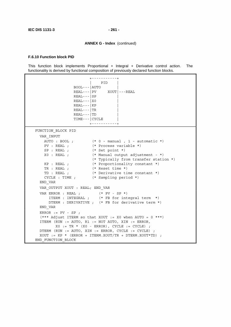
IEC DIS 1131-3 - 261 -
ANNEX G - Index (continued)
F.6.10 Function block PID
This function block implements Proportional + Integral + Derivative control action. The functionality is derived by functional composition of previously declared function blocks.
+-----------+ | PID | BOOL---|AUTO | REAL---|PV XOUT|---REAL REAL---|SP | REAL---|X0 | REAL---|KP | REAL---|TR | REAL---|TD | TIME---|CYCLE | +-----------+
FUNCTION_BLOCK PID
VAR_INPUT AUTO : BOOL ; (* 0 - manual , 1 - automatic *) PV : REAL ; (* Process variable *) SP : REAL ; (* Set point *) X0 : REAL ; (* Manual output adjustment - *) (* Typically from transfer station *) KP : REAL ; (* Proportionality constant *) TR : REAL ; (* Reset time *) TD : REAL ; (* Derivative time constant *) CYCLE : TIME ; (* Sampling period *) END_VAR
VAR_OUTPUT XOUT : REAL; END_VAR
VAR ERROR : REAL ; (* PV - SP *) ITERM : INTEGRAL ; (* FB for integral term *) DTERM : DERIVATIVE ; (* FB for derivative term *) END_VAR
ERROR := PV - SP ; (*** Adjust ITERM so that XOUT := X0 when AUTO = 0 ***) ITERM (RUN := AUTO, R1 := NOT AUTO, XIN := ERROR, X0 := TR * (X0 - ERROR), CYCLE := CYCLE) ; DTERM (RUN := AUTO, XIN := ERROR, CYCLE := CYCLE) ; XOUT := KP * (ERROR + ITERM.XOUT/TR + DTERM.XOUT*TD) ; END_FUNCTION_BLOCK

- 262 - IEC DIS 1131-3
ANNEX G - Index (continued)
F.6.11 Function block DIFFEQ
This function block implements a general difference equation.
+-----------+ | DIFFEQ | BOOL---|RUN | REAL---|XIN XOUT|---REAL ARRAY[1..] OF REAL---|A | INT----|M | ARRAY[0..] OF REAL---|B | INT----|N | +-----------+
FUNCTION_BLOCK DIFFEQ
VAR_INPUT RUN : BOOL ; (* 1 = run, 0 = reset *) XIN : REAL ; A : ARRAY[1..] OF REAL ; (* Input coefficients *) M : INT ; (* Length of input history *) B : ARRAY[0..] OF REAL ; (* Output coefficients *) N : INT ; (* Length of output history *) END_VAR
VAR_OUTPUT XOUT : REAL := 0.0 ; END_VAR
VAR (* NOTE : Manufacturer may specify other array sizes *) XI : ARRAY [0..128] OF REAL ; (* Input history *) XO : ARRAY [0..128] OF REAL ; (* Output history *) I : INT ; END_VAR
XO[0] := XOUT ; XI[0] := XIN ; XOUT := B[0] * XIN ; IF RUN THEN FOR I := M TO 1 BY -1 DO XOUT := XOUT + A[I] * XO[I] ; XO[I] := XO[I-1]; END_FOR; FOR I := N TO 1 BY -1 DO XOUT := XOUT + B[I] * XI[I] ; XI[I] := XI[I-1]; END_FOR; ELSE FOR I := 1 TO M DO XO[I] := 0.0; END_FOR; FOR I := 1 TO N DO XI[I] := 0.0; END_FOR; END_IF ;
END_FUNCTION_BLOCK
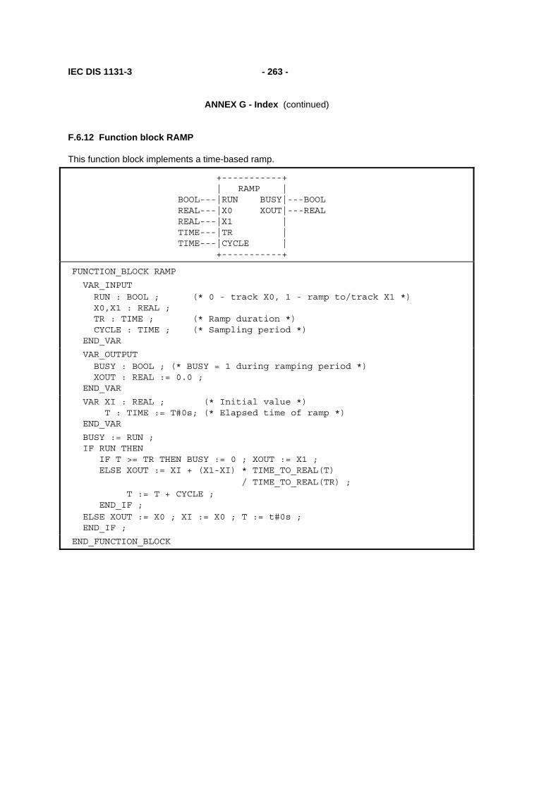
IEC DIS 1131-3 - 263 -
ANNEX G - Index (continued)
F.6.12 Function block RAMP
This function block implements a time-based ramp.
+-----------+ | RAMP | BOOL---|RUN BUSY|---BOOL REAL---|X0 XOUT|---REAL REAL---|X1 | TIME---|TR | TIME---|CYCLE | +-----------+
FUNCTION_BLOCK RAMP
VAR_INPUT RUN : BOOL ; (* 0 - track X0, 1 - ramp to/track X1 *) X0,X1 : REAL ; TR : TIME ; (* Ramp duration *) CYCLE : TIME ; (* Sampling period *) END_VAR
VAR_OUTPUT BUSY : BOOL ; (* BUSY = 1 during ramping period *) XOUT : REAL := 0.0 ; END_VAR
VAR XI : REAL ; (* Initial value *) T : TIME := T#0s; (* Elapsed time of ramp *) END_VAR
BUSY := RUN ; IF RUN THEN IF T >= TR THEN BUSY := 0 ; XOUT := X1 ; ELSE XOUT := XI + (X1-XI) * TIME_TO_REAL(T) / TIME_TO_REAL(TR) ; T := T + CYCLE ; END_IF ; ELSE XOUT := X0 ; XI := X0 ; T := t#0s ; END_IF ;
END_FUNCTION_BLOCK

- 264 - IEC DIS 1131-3
ANNEX G - Index (continued)
F.6.13 Function block TRANSFER
This function block implements a manual transfer station with bumpless transfer.
+-----------+ | TRANSFER | BOOL---|AUTO | REAL---|XIN XOUT|---REAL REAL---|FAST_RATE | REAL---|SLOW_RATE | BOOL---|FAST_UP | BOOL---|SLOW_UP | BOOL---|FAST_DOWN | BOOL---|SLOW_DOWN | TIME---|CYCLE | +-----------+
FUNCTION_BLOCK TRANSFER
VAR_INPUT
AUTO : BOOL ; (* 1 - track X0, 0 - ramp or hold *) XIN : REAL ; (* Typically from PID Function Block *) FAST_RATE, SLOW_RATE : REAL ; (* Up/down ramp slopes *) FAST_UP, SLOW_UP, (* Typically pushbuttons *) FAST_DOWN, SLOW_DOWN : BOOL; CYCLE : TIME ; (* Sampling period *) END_VAR
VAR_OUTPUT XOUT : REAL ; END_VAR
VAR XFER_RAMP : INTEGRAL ; RAMP_RATE : REAL ; END_VAR
RAMP_RATE := 0.0 ; IF NOT AUTO THEN IF FAST_UP THEN RAMP_RATE := FAST_RATE; END_IF; IF SLOW_UP THEN RAMP_RATE := RAMP_RATE + SLOW_RATE; END_IF; IF FAST_DOWN THEN RAMP_RATE := RAMP_RATE - FAST_RATE; END_IF; IF SLOW_DOWN THEN RAMP_RATE := RAMP_RATE - SLOW_RATE; END_IF; END_IF ; XFER_RAMP (RUN := 1, CYCLE := CYCLE, R1 := AUTO, XIN := RAMP_RATE, X0 := XIN) ; XOUT := XFER_RAMP.XOUT;
END_FUNCTION_BLOCK

IEC DIS 1131-3 - 265 -
ANNEX G - Index (continued)
F.7 Program GRAVEL
A control system is to be used to measure an operator-specified amount of gravel from a silo into an intermediate bin, and to convey the gravel after measurement from the bin into a truck.
The quantity of gravel to be transferred is specified via a thumbwheel with a range of 0 to 99 units. The amount of gravel in the bin is indicated on a digital display.
For safety reasons, visual and audible alarms must be raised immediately when the silo is empty. The signalling functions are to be implemented in the control program.
A graphic representation of the control problem is shown in figure F.2, while the variable declarations for the control program are given in figure F.3.
As shown in figure F.4, the operation of the system consists of a number of major states, beginning with filling of the bin upon command from the FILL push button. After the bin is filled, the truck loading sequence begins upon command by the LOAD pushbutton when a truck is present on the ramp. Loading consists of a "run-in" period for starting the conveyor, followed by dumping of the bin contents onto the conveyor. After the bin has emptied, the conveyor "runs out" for a predetermined time to assure that all gravel has been loaded to the truck. The loading sequence is stopped and re-initialized if the truck leaves the ramp or if the automatic control is stopped by the OFF push button.
Figure F.5 shows the OFF/ON sequence of automatic control states, as well as the generation of display blinking pulses and conveyor motor gating when the control is ON.
Bin level monitoring, operator interface and display functions are defined in figure F.6.
A textual version of the body of program GRAVEL is given in figure F.7, using the ST language with SFC elements.
An example configuration for program GRAVEL is given in figure F.8.
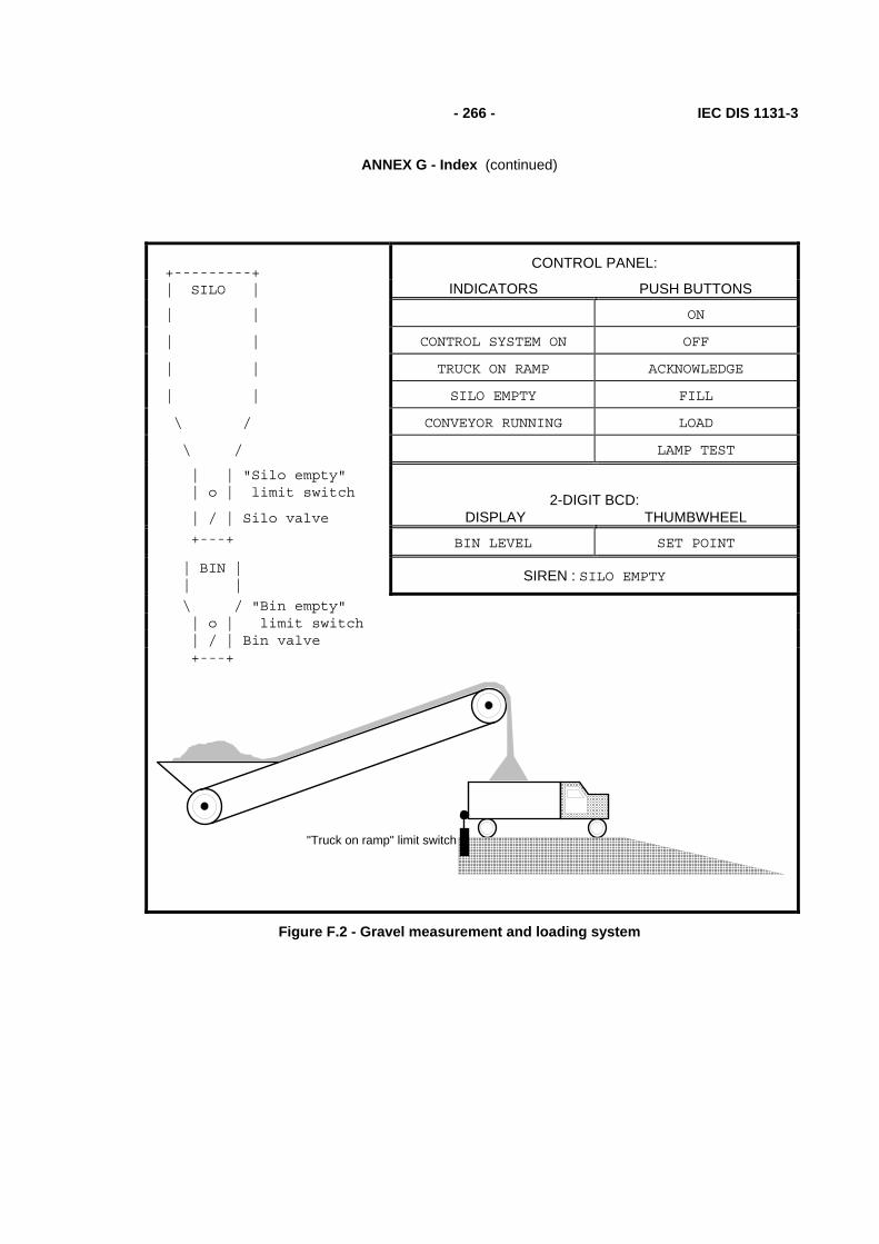
- 266 - IEC DIS 1131-3
ANNEX G - Index (continued)
+---------+
CONTROL PANEL:
| SILO | INDICATORS PUSH BUTTONS
| | ON
| | CONTROL SYSTEM ON OFF
| | TRUCK ON RAMP ACKNOWLEDGE
| | SILO EMPTY FILL
\ / CONVEYOR RUNNING LOAD
\ / LAMP TEST
| | "Silo empty" | o | limit switch
2-DIGIT BCD:
| / | Silo valve DISPLAY THUMBWHEEL +---+ BIN LEVEL SET POINT
| BIN | | |
SIREN : SILO EMPTY
\ / "Bin empty" | o | limit switch | / | Bin valve +---+
"Truck on ramp" limit switch
Figure F.2 - Gravel measurement and loading system

IEC DIS 1131-3 - 267 -
ANNEX G - Index (continued)
PROGRAM GRAVEL (* Gravel measurement and loading system *)
VAR_INPUT OFF_PB : BOOL ; ON_PB : BOOL ; FILL_PB : BOOL ; SIREN_ACK : BOOL ; LOAD_PB : BOOL ; (* Load truck from bin *) JOG_PB : BOOL ; LAMP_TEST : BOOL ; TRUCK_ON_RAMP : BOOL ; (* Optical sensor *) SILO_EMPTY_LS : BOOL ; BIN_EMPTY_LS : BOOL ; SETPOINT : BYTE ; (* 2-digit BCD *) END_VAR
VAR_OUTPUT CONTROL_LAMP : BOOL ; TRUCK_LAMP : BOOL ; SILO_EMPTY_LAMP : BOOL ; CONVEYOR_LAMP : BOOL ; CONVEYOR_MOTOR : BOOL ; SILO_VALVE : BOOL ; BIN_VALVE : BOOL ; SIREN : BOOL ; BIN_LEVEL : BYTE ; END_VAR
VAR BLINK_TIME : TIME; (* BLINK ON/OFF time *) PULSE_TIME : TIME; (* LEVEL_CTR increment interval *) RUNOUT_TIME: TIME; (* Conveyor running time after loading *) RUN_IN_TIME: TIME; (* Conveyor running time before loading *) SILENT_TIME: TIME; (* Siren silent time after SIREN_ACK *) OK_TO_RUN : BOOL; (* 1 = Conveyor is allowed to run *)
(* Function Blocks *) BLINK: TON; (* Blinker OFF period timer / ON output *) BLANK: TON; (* Blinker ON period timer / blanking pulse *) PULSE: TON; (* LEVEL_CTR pulse interval timer *) SIREN_FF: RS; SILENCE_TMR: TP; (* Siren silent period timer *) END_VAR
VAR RETAIN LEVEL_CTR : CTU ; END_VAR
(* Program body *)
END_PROGRAM
Figure F.3 - Declarations for Program GRAVEL
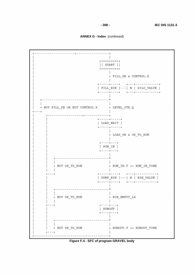
- 268 - IEC DIS 1131-3
ANNEX G - Index (continued)
+--------------------->-----------------+ | | | +====+====+ | || START || | +====+====+ | | | + FILL_PB & CONTROL.X | | | +-----+----+ +---+------------+ | | FILL_BIN |---| N | SILO_VALVE | | +-----+----+ +---+------------+ | | | +-----------------------------------* | | | | + NOT FILL_PB OR NOT CONTROL.X + LEVEL_CTR.Q +---+ | | +------------------>-------------+ | | +-----+-----+ | | | LOAD_WAIT | | | +-----+-----+ | | | | | + LOAD_PB & OK_TO_RUN | | | | | +----+---+ | | | RUN_IN | | | +----+---+ | | | | | +----------------------------* | | | | | | + NOT OK_TO_RUN + RUN_IN.T >= RUN_IN_TIME | | | | | +---+ +-----+----+ +---+-----------+ | | | DUMP_BIN |---| N | BIN_VALVE | | | +-----+----+ +---+-----------+ | | | | | +----------------------------* | | | | | | + NOT OK_TO_RUN + BIN_EMPTY_LS | | | | | +---+ +----+---+ | | | RUNOUT | | | +----+---+ | | | | | +----------------------------* | | | | | | + NOT OK_TO_RUN + RUNOUT.T >= RUNOUT_TIME | +---+ | +---------------------------------------+
Figure F.4 - SFC of program GRAVEL body

IEC DIS 1131-3 - 269 -
ANNEX G - Index (continued)
+---------+ | | | + OFF_PB | | | +======+======+ +===========+ +---+----------------+ | ||CONTROL_OFF|| || MONITOR ||---| N | MONITOR_ACTION | | +======+======+ +===========+ +---+----------------+ | | | + ON_PB & NOT OFF_PB | | | +---+---+ +---+----------------------------------+-----+ | |CONTROL|--| N | CONTROL_ACTION | | | +---+---+ +---+----------------------------------+-----+ | | | +---------------------------------+ | +---------+ | | BLINK BLANK | | | | +-+ +-----+ +-----+ | | | +---O|&| | TON | | TON | | | |CONTROL.X--| |-----|IN Q|-----|IN Q|--+ | | +-+ +--|PT | +--|PT | | | | +-----+ | +-----+ | | BLINK_TIME--+-----------+ | | +-+ | |CONTROL.X------|&| | |TRUCK_ON_RAMP--| |---+---------OK_TO_RUN | | +-+ | | | | +-+ | | +-----+ +--|&|--CONVEYOR_MOTOR | |JOG_PB------| >=1 |-----| | | |RUN_IN.X----| | +-+ | |DUMP_BIN.X--| | | |RUNOUT.X----| | | | +-----+ | +--------------------------------------------+
Figure F.5 - Body of program GRAVEL (continued) Control state sequencing and monitoring
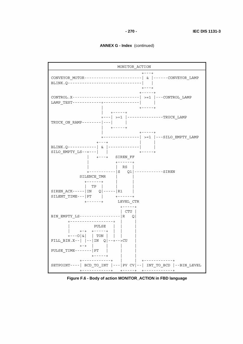
- 270 - IEC DIS 1131-3
ANNEX G - Index (continued)
MONITOR_ACTION
+---+ CONVEYOR_MOTOR------------------------| & |------CONVEYOR_LAMP BLINK.Q-------------------------------| | +---+ +-----+ CONTROL.X----------------------------| >=1 |---CONTROL_LAMP LAMP_TEST------------+---------------| | | +-----+ | +-----+ +---| >=1 |---------------TRUCK_LAMP TRUCK_ON_RAMP--------|---| | | +-----+ | +-----+ +---------------| >=1 |---SILO_EMPTY_LAMP +---+ | | BLINK.Q------------| & |-------------| | SILO_EMPTY_LS--+---| | +-----+ | +---+ SIREN_FF | +------+ | | RS | +-----------|S Q1|------------SIREN SILENCE_TMR | | +------+ | | | TP | | | SIREN_ACK-----|IN Q|-----|R1 | SILENT_TIME---|PT | +------+ +------+ LEVEL_CTR +-----+ | CTU | BIN_EMPTY_LS-----------------|R Q| +------------------+ | | | PULSE | | | | +-+ +-----+ | | | +---O|&| | TON | | | | FILL_BIN.X--| |--|IN Q|--+-->CU | +-+ | | | | PULSE_TIME-------|PT | | | +-----+ | | +------------+ | | +------------+ SETPOINT----| BCD_TO_INT |---|PV CV|--| INT_TO_BCD |--BIN_LEVEL +------------+ +-----+ +------------+
Figure F.6 - Body of action MONITOR_ACTION in FBD language

IEC DIS 1131-3 - 271 -
ANNEX G - Index (continued)
(* Major operating states *)
INITIAL_STEP START : END_STEP
TRANSITION FROM START TO FILL_BIN := FILL_PB & CONTROL.X ; END_TRANSITION
STEP FILL_BIN: SILO_VALVE(N); END_STEP
TRANSITION FROM FILL_BIN TO START := NOT FILL_PB OR NOT CONTROL.X ; END_TRANSITION TRANSITION FROM FILL_BIN TO LOAD_WAIT := LEVEL_CTR.Q ; END_TRANSITION
STEP LOAD_WAIT : END_STEP
TRANSITION FROM LOAD_WAIT TO RUN_IN := LOAD_PB & OK_TO_RUN ; END_TRANSITION
STEP RUN_IN : END_STEP
TRANSITION FROM RUN_IN TO LOAD_WAIT := NOT OK_TO_RUN ; END_TRANSITION
TRANSITION FROM RUN_IN TO DUMP_BIN := RUN_IN.T > RUN_IN_TIME; END_TRANSITION
STEP DUMP_BIN: BIN_VALVE(N); END_STEP
TRANSITION FROM DUMP_BIN TO LOAD_WAIT := NOT OK_TO_RUN ; END_TRANSITION
TRANSITION FROM DUMP_BIN TO RUNOUT := BIN_EMPTY_LS ; END_TRANSITION
STEP RUNOUT : END_STEP
TRANSITION FROM RUNOUT TO LOAD_WAIT := NOT OK_TO_RUN ; END_TRANSITION
TRANSITION FROM RUNOUT TO START := RUNOUT.T >= RUNOUT_TIME ; END_TRANSITION
Figure F.7 - Body of program GRAVEL in textual SFC representation using ST language elements (continued on following page)

- 272 - IEC DIS 1131-3
ANNEX G - Index (continued)
(* Control state sequencing *)
INITIAL_STEP CONTROL_OFF: END_STEP
TRANSITION FROM CONTROL_OFF TO CONTROL := ON_PB & NOT OFF_PB ; END_TRANSITION
STEP CONTROL: CONTROL_ACTION(N); END_STEP
ACTION CONTROL_ACTION: BLINK(EN:=CONTROL.X & NOT BLANK.Q, PT := BLINK_TIME) ; BLANK(EN:=BLINK.Q, PT := BLINK_TIME) ; OK_TO_RUN := CONTROL.X & TRUCK_ON_RAMP ; CONVEYOR_MOTOR := OK_TO_RUN & OR(JOG_PB, RUN_IN.X, DUMP_BIN.X, RUNOUT.X); END_ACTION
TRANSITION FROM CONTROL TO CONTROL_OFF := OFF_PB ; END_TRANSITION
(* Monitor Logic *)
INITIAL_STEP MONITOR: MONITOR_ACTION(N); END_STEP
ACTION MONITOR_ACTION: CONVEYOR_LAMP := CONVEYOR_MOTOR & BLINK.Q ; CONTROL_LAMP := CONTROL.X OR LAMP_TEST ; TRUCK_LAMP := TRUCK_ON_RAMP OR LAMP_TEST ; SILO_EMPTY_LAMP := BLINK.Q & SILO_EMPTY_LS OR LAMP_TEST ; SILENCE_TMR(EN:=SIREN_ACK, PT:=SILENT_TIME) ; SIREN_FF(S:=SILO_EMPTY_LS, R1:=SILENCE_TMR.Q) ; SIREN := SIREN_FF.Q1 ; PULSE(EN:=FILL_BIN.X & NOT PULSE.Q, PT:=PULSE_TIME) ; LEVEL_CTR(EN := BIN_EMPTY_LS, CU := PULSE.Q, PV := BCD_TO_INT(SETPOINT)) ; BIN_LEVEL := INT_TO_BCD(LEVEL_CTR.CV) ; END_ACTION
Figure F.7 - Body of program GRAVEL in textual SFC representation using ST language elements (continued)

IEC DIS 1131-3 - 273 -
ANNEX G - Index (continued)
CONFIGURATION GRAVEL_CONTROL
RESOURCE PROC1 ON PROC_TYPE_Y
PROGRAM G : GRAVEL (* Inputs *) (OFF_PB := %I0.0 , ON_PB := %I0.1 , FILL_PB := %I0.2 , SIREN_ACK := %I0.3 , LOAD_PB := %I0.4 , JOG_PB := %I0.5 , LAMP_TEST := %I0.7 , TRUCK_ON_RAMP := %I1.4 , SILO_EMPTY_LS := %I1.5 , BIN_EMPTY_LS := %I1.6 , SETPOINT := %IB2 ,
(* Outputs *) CONTROL_LAMP => %Q4.0, TRUCK_LAMP => %Q4.2, SILO_EMPTY_LAMP => %Q4.3, CONVEYOR_LAMP => %Q5.3, CONVEYOR_MOTOR => %Q5.4, SILO_VALVE => %Q5.5, BIN_VALVE => %Q5.6, SIREN => %Q5.7, BIN_LEVEL => %B6) ;
END_RESOURCE
END_CONFIGURATION
Figure F.8 - Example configuration for program GRAVEL

- 274 - IEC DIS 1131-3
ANNEX G - Index (continued)
F.8 Program AGV
As illustrated in figure F.9, a program is to be devised to control an automatic guided vehicle (AGV). The AGV is to travel between two extreme positions, left (indicated by limit switch S3) and right (indicated by limit switch S4). The normal position of the AGV is on the left.
The AGV is to execute one cycle of left-to-right and return motion when the operator actuates pushbutton S1, and two cycles when the operator actuates pushbutton S2. It is also possible to pass from a single to a double cycle by actuating pushbutton S2 during a single cycle. Finally, non-repeat locking is to be provided if either S1 or S2 remains actuated.
Figure F.10 illustrates the graphical declaration of program AGV, while figure F.11 shows a typical configuration for this program. Figure F.12 shows the AGV program body, consisting of a main control sequence and a single-cycle control sequence.
LEFT_LS RIGHT_LSFWD_MOTORREV_MOTOR
1 Cycle 2 Cycles
AGV Control Panel
SINGLE_PB DOUBLE_PB
Figure F.9 - Physical model for program AGV

IEC DIS 1131-3 - 275 -
ANNEX G - Index (continued)
+----------------------+ | AGV | BOOL---|SINGLE_PB FWD_MOTOR|---BOOL BOOL---|DOUBLE_PB REV_MOTOR|---BOOL BOOL---|LEFT_LS | BOOL---|RIGHT_LS | +----------------------+
Figure F.10 - Graphical declaration of program AGV
CONFIGURATION AGV_CONTROL
RESOURCE AGV_PROC: SMALL_PC
AGV_1 +--------------------+ | AGV | %IX1---|SINGLE_PB FWD_MOTOR|---%QX1 %IX2---|DOUBLE_PB REV_MOTOR|---%QX2 %IX3---|LEFT_LS | %IX4---|RIGHT_LS | +--------------------+
Figure F.11 - A graphical configuration of program AGV
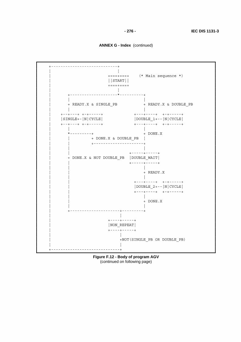
- 276 - IEC DIS 1131-3
ANNEX G - Index (continued)
+----------------------------+ ¦ ¦ ¦ +===+===+ (* Main sequence *) ¦ |¦START¦| ¦ +===+===+ ¦ ¦ ¦ +--------------------*----------+ | | | ¦ + READY.X & SINGLE_PB + READY.X & DOUBLE_PB | | | ¦ +--+---+ +-+-----+ +---+----+ +-+-----+ ¦ ¦SINGLE+-¦N¦CYCLE¦ ¦DOUBLE_1+--¦N¦CYCLE¦ ¦ +--+---+ +-+-----+ +---+----+ +-+-----+ | | | ¦ *---------+ + DONE.X ¦ ¦ + DONE.X & DOUBLE_PB ¦ ¦ ¦ +---------------------+ | | | ¦ ¦ +-----+-----+ ¦ + DONE.X & NOT DOUBLE_PB ¦DOUBLE_WAIT¦ ¦ ¦ +-----+-----+ | | | ¦ ¦ + READY.X | | | ¦ ¦ +---+----+ +-+-----+ ¦ ¦ ¦DOUBLE_2+--¦N¦CYCLE¦ ¦ ¦ +---+----+ +-+-----+ | | | ¦ ¦ + DONE.X | | | ¦ +---------------------+---------+ ¦ ¦ ¦ +----+-----+ ¦ ¦NON_REPEAT¦ ¦ +----+-----+ ¦ ¦ ¦ +NOT(SINGLE_PB OR DOUBLE_PB) ¦ ¦ +-----------------------------+
Figure F.12 - Body of program AGV (continued on following page)

IEC DIS 1131-3 - 277 -
ANNEX G - Index (continued)
+-------+ ¦ | ¦ +===+===+ (* Perform a single cycle *) ¦ |¦READY¦| ¦ +===+===+ ¦ | ¦ + CYCLE ¦ | ¦ +---+---+ +-+---------+ ¦ ¦FORWARD+-¦N¦FWD_MOTOR¦ ¦ +---+---+ +-+---------+ ¦ | ¦ + RIGHT_LS ¦ | ¦ +---+---+ +-+---------+ ¦ ¦REVERSE+-¦N¦REV_MOTOR¦ ¦ +---+---+ +-+---------+ ¦ | ¦ + LEFT_LS ¦ | ¦ +--+-+ ¦ ¦DONE¦ ¦ +--+-+ ¦ | ¦ + NOT CYCLE ¦ | +-------+
Figure F.12 - Body of program AGV (continued)

- 278 - IEC DIS 1131-3
ANNEX G - Index (continued)

IEC DIS 1131-3 - 279 -
ANNEX G - Index (continued)
ANNEX G - Index (informative)
Primary references for delimiters and keywords are given in annex C. The point of definition of a term is shown in bold face type.
absolute time, 29
access path, 105, 107-9 communication, 15-18 keyword, 40 loading/deletion, 15 programming, 19-20
action, 77, 83-92, 118, 120 control, 88-92 qualifiers, 88
action block, 83, 86, 87, 88
active association, 88, 89
activity flow, 128
aggregate, 10
argument, 44, 61, 120, 121, 122
array, 44 access path, 107 declaration, 33-34, 41 initialization, 33, 42-43 location assignment, 41 usage, 38, 127
assignment, 45, 46, 47, 79 FOR loop variable values, 126 function block parameters, 62 of input values, 125 operator, 33, 79 statement, 124, 125
based number, 10, 27-28
basic code table, 24
bistable function block, 70-71
bit string comparison, 54 data types, 30-32 functions, 54-55 initial value assignment, 42-43 variable declaration, 40-41
body function, 46, 47, 48, 125 function block, 61-76
- 280 - IEC DIS 1131-3
ANNEX G - Index (continued)
program organization unit, 130
IEC DIS 1131-3 - 281 -
ANNEX G - Index (continued)
Boolean AND, in ladder diagrams, 135 data type, 30-32 default initial value, 34 edge detection, 63, 72 expression, 79, 122, 126, 127 functions, 54-55, 89 input, action control, 88, 89 input, RETURN, 132 literals, 27-28 negation, 45, 119 operators, 120, 123 OR, LD vs. FBD, 138 output, 132 signal, 132 values, power flow, 134 variable, 38, 77, 78, 83, 84, 87, 88, 110, 126, 132 variable, in ladder diagrams, 135, 137
byte (data element size), 38
BYTE (data type), 30-32, 34
call operator, 120, 121
case (of characters), 24, 25, 29
CASE statement, 124, 126
character code, 24, 26, 28, 58
character set, 9, 24-25, 77, 99, 128, 136
character string character positions in, 58 comparison, 58 data type, 30-32 functions, 58-59 initialization, 42-43 literals, 28 variable declaration, 40-41
cold restart, 39, 40, 41, 42, 43
comment, 26, 119
comparison bit strings, 54 character strings, 58 functions, 54, 59
compilation, 22

- 282 - IEC DIS 1131-3
ANNEX G - Index (continued)
compliance, 21-23 action declarations, 83 EXIT statement, 125 PC systems, 21 programs, 23 sequential function chart (SFC), 104 step/action association, 86 syntax, 22
concatenation action blocks, 86, 87 hierarchical addresses, 37 time data, 60
conditional call, 121 instruction, 120 jump, 132 return, 132
configuration, 14-15 communication, 15-18 elements, 105-17 initialization, 15 programming, 19-20 starting and stopping, 15
connection, 17, 76
connector, 79, 81, 128, 129
contact, 135-36
counter, 73
data type compliance, 22 declaration, 33-34 elementary, 30-32 generic, 32, 48, 49 initialization, 34-35 of an expression, 122 of functions, 47 of input parameters, 47 of internal variables, 47 programming, 19-20 usage, 36
date and time, 74 data types, 30-32 default initial values, 34 functions, 59 literals, 30
decimal number (decimal literal), 27-28, 128
declaration, 19-20 access paths, 107-9 actions, 83-85, 88 configurations, 105-17

IEC DIS 1131-3 - 283 -
ANNEX G - Index (continued)
data types, 33-34 function blocks, 61, 62-69 functions, 47-48, 125 programs, 76 resources, 107-9 tasks, 110-17 variables, 39-40, 137
default value, 48 FOR increment, 126 function block inputs, 63 of data types, 34-35 of variables, 39, 42-43 task interval, 110
delimiter comments, 26 LD network, 134 network label, 128 time literals, 29-30
direct representation, 37-38, 76, 107, 108 in programs, 76 initial value assignment, 42-43 variable declaration, 40-41
double word, 30-32 size prefix, 38
duration data type (TIME), 30-32 literals, 29 of action qualifiers, 88 of step activity, 93
edge detection, 63, 66 function blocks, 72
EN/ENO (enable) variables, 46, 47
errors, 44, 48, 78, 89, 93, 125, 127, 128 documentation, 22 handling, 22, 23, 46 reporting, 22
- 284 - IEC DIS 1131-3
ANNEX G - Index (continued)
evaluation of assignment statements, 125 of CASE expressions, 126 of expressions, 122-23 of function blocks, 111 of functions, 44, 53, 123, 125 of instructions, 119-21 of language elements, 111 of network elements, 130 of networks, 61, 130-31, 135, 138 of programs, 111 of transitions, 94, 95, 96, 97
execution of actions, 77, 88 of EXIT statements, 127 of function blocks, 61, 72, 110 of functions, 44, 46-47 of instructions, 119-21 of iteration statements, 126-27 of loop elements, 130 of programs, 132 of selection statements, 126
execution control element, 77, 110, 130, 132-33, 135
extensions, 22, 24, 26, 37 documentation, 22 processing, 22 usage, 23
falling edge, 63, 65, 72
feedback path, 130, 131 variable, 130
FOR statement, 126-27
function, 44-60 compliance, 22 control statements, 125-26 extensible, 50 in LD language, 135 overloaded, 48, 49, 52, 54 programming, 19-20 return value, 125 signal flow, 128 typing, 48
IEC DIS 1131-3 - 285 -
ANNEX G - Index (continued)
function block, 14-15, 61-76 action control, 88-92 communication, 15-18, 76 compliance, 22 control statements, 125-26 in LD language, 135 instance, 110 operation, 73, 74 programming, 19-20 retentive, 78 SFC structuring, 77 signal flow, 128 type, 61
function block diagram (FBD), 14, 138 execution control, 132-33 loops in, 130 signal flow in, 128
function block diagram (fbd) action blocks in, 87
generic data types, 32, 48, 49
global variable, 105 communication, 15, 17 declaration, 39-40, 76, 107-9 function block instance, 61 initial value assignment, 42-43 initialization, 15 loading/deletion, 15 programming, 19-20
hierarchical addressing, 37
identifier, 25, 47, 61, 77, 79, 123, 128
implementation-dependent feature, 22, 23, 39, 41, 126 parameter, 21, 33, 37, 38, 50, 73, 93 side effects, 62
initial state, 77 step, 77, 78, 93
initial value assignment, 42-43 default, 34-35 feedback variable, 130 FOR loop variable, 126 function block variables, 63, 125
initialization, 15, 39 function blocks, 62-69, 93 programs, 76, 93 SFC networks, 93

- 286 - IEC DIS 1131-3
ANNEX G - Index (continued)
steps, 78
input declaration, 39-40, 47-48, 62-69 dynamic, 63 extensible, 50 initialization, 39 instance name, 61 location prefix, 38 negated, 45 operators (IL language), 121 overloaded, 48, 49 parameter, 44, 61, 125 parameter, read/write privileges, 62 program, 108 string, 51 variable, 61, 76, 107, 135
input/output parameter, 62-69 variable, 61
instance function block, 61, 63, 65, 110 name, 61, 63, 65
instantiation action control, 89 function block, 76 program, 76
instruction, 79, 83, 119-21
integer data types, 30-32, 126 literal, 12, 27-28, 128
invocation by tasks, 110 function block, 61, 62, 63, 121, 124, 125-26, 125 of actions, 77 of functions, 44, 45, 121, 122-23 of non-PC language elements, 19 recursive, 44 return from, 132
iteration, 125, 126-27
IEC DIS 1131-3 - 287 -
ANNEX G - Index (continued)
keyword, 26 Boolean literals, 27, 79 data types, 30-32 ELSE statement, 126 FOR statement, 126 function block declaration, 63 function declaration, 47 IF statement, 126 program declaration, 76 REPEAT statement, 127 time literals, 29-30 transition, 79 variable declaration, 39-40 WHILE statement, 127
label, 119, 120 connector, 128 network, 128, 130, 132
ladder diagram, 134-37 evaluation, 130-31 execution control, 132-33 network, 79
language element, 9, 14-15 compliance, 21-23 programming, 19-20, 76
library, 19-20, 107
literal, 27-30, 119, 122, 134
logical location, 37, 39, 40
long real, 30-32
long word, 30-32
memory, 135
memory (user data storage) allocation, 39-40, 137 direct representation, 37-38 initial value assignment, 42-43 initialization, 39
named element, 38, 125, 128
network, 88, 128 direction of flow, 128 evaluation, 61, 130-31, 135, 138 function block diagram (FBD), 79, 83 label, 132 ladder diagram (LD), 79, 134 sequential function chart (SFC), 77, 91, 93
numeric literals, 27-28
off-delay, 13, 74-75

- 288 - IEC DIS 1131-3
ANNEX G - Index (continued)
on-delay, 13, 74-75
operand function as, 44 of an expression, 122-23 of an instruction, 119-21
operator assignment, 33, 79, 125 Instruction List, 119-21 overloaded, 48 precedence, 122, 123 Structured Text (ST), 122-23 symbols, 53, 55, 56, 57
output action control, 88 declaration, 62-69 function block, 124, 138 graphical representation, 45, 61 location prefix, 38 negated, 45 network, 138 parameter(s), 45, 61 parameter, read/write privileges, 62 program, 108 string, 51 typed, 48 values, 61 variable declaration, 39-40 variables, 61, 76, 107, 135
overloading, 32, 48 of operators, 120, 122
parameter actual, 45, 49, 135 formal, 45, 49, 61, 135 formal, declaration, 47-48, 62-69, 76 input, 44, 61, 125 output, 45, 61 passing, 39, 63
parentheses, 26, 33, 38, 42, 79, 120, 123, 125
power flow, 87, 128, 132, 134, 135
power rails, 128, 132, 134
pre-emptive scheduling, 110-17
priority of tasks, 110-17 of transitions, 94, 95, 96, 97

IEC DIS 1131-3 - 289 -
ANNEX G - Index (continued)
program, 14-15, 19-20, 76 communication, 15-18 compliance, 23 declaration, 39, 61, 68, 76, 108 retentive, 78 scheduling, 110-17 semaphore use in, 71 SFC structuring, 77
program organization unit, 44, 61 compliance, 21 declaration, 39, 44 initial state, 77 jumps in, 132 networks in, 128, 130, 135, 138 scheduling, 110-17 SFC partitioning of, 77 state, 77
programming, 15, 19-20, 134, 138
real literal, 27-28
resource, 14-15, 76 communication, 18 declaration, 107-9 global variables in, 107 initialization, 15, 39 programming, 19-20 starting and stopping, 15, 110
retentive data declaration, 39-40, 76, 137 in function blocks, 63 in steps, 78 initial value assignment, 42 initialization, 39 keyword, 40 type assignment, 40-41
return, 120, 121, 124, 125, 132
rising edge, 63, 65, 72, 74, 110
rung, 83, 134
scope global, 107 of actions, 83 of declarations, 39 of function block instances, 61 of networks, 128 of steps, 77 of transitions, 80
selection functions, 54, 59
- 290 - IEC DIS 1131-3
ANNEX G - Index (continued)
statements, 126
semantics Instruction List (IL), 119-21 Structured Text (ST), 122-27
semigraphic representation, 9, 63, 109, 128, 129
sequential function chart (SFC) activity flow, 128 compliance, 104 convergence, simultaneous, 93 divergence, selection, 94, 95, 96, 97 divergence, simultaneous, 93 elements, 14, 70, 71, 77-92, 118, 127, 128 elements, compatibility of, 104 errors, 93 evolution, 93-103 programming, 19
signal flow, 128, 138
single data element, 36, 37-38
step, 77-78 action association, 86 activation, 93 active, 77, 78, 88, 93 deactivation, 77, 85, 93 duration, 93 elapsed time, 77, 78 flag, 77, 78 inactive, 77, 134 initial, 77, 78, 93 initialization, 78 retentive, 78 state, 77, 93, 94, 95, 96, 97, 100, 101
structured data type, 61 declaration, 33-34 initialization, 34-35 usage, 36
structured variable, 38, 44 access path, 107 assignment, 125 declaration, 41 initialization, 42-43 step elements, 77
subscripting, 38 array initialization, 42
symbolic representation, 37, 40
synchronization interprocess, 127 of function blocks, 110-17
syntax, 14

IEC DIS 1131-3 - 291 -
ANNEX G - Index (continued)
documentation, 22 step/transition, 93
task, 14-15, 110-17 declaration, 107-9 programming, 19-20
TIME data type, 30-32, 77, 78, 88 default initial value, 34 function blocks, 74 functions, 60
time literal, 29-30
time of day data types, 30-32 default initial value, 34 functions, 60 keywords, 30 literals, 29-30
timer, 74-75
transition, 77, 79-82 clearing, 93, 101 clearing time, 93 condition, 77, 79-82, 83, 93 enabled, 93, 100 evaluation, 94, 95, 96, 97 priority, 94, 95, 96, 97 symbol, 93
type conversion functions, 49, 50-51
underline character, 25, 27, 48
unsigned integer, 128 data types, 30

- 292 - IEC DIS 1131-3
ANNEX G - Index (continued)
variable, 37-43 declaration, 47-48, 62-69 usage, 36
WAIT function, 83, 127
warm restart, 39
wired OR, 138
IEC DIS 1131-3 - 293 -
ANNEX H - Software compliance testing (informative)
This topic is under consideration for future standardization.
-- END OF PART 3 --