contents · 8.drilling machine with dividing attachment 28 1 ... tailstock z007 2 set center needle...
TRANSCRIPT

Table Of Contents
About Zhouyu Mini Multipurpose Machine
Part List Of 8 in 3 Kit Set
Part List Of 6 in 1 Kit Set 6
Parts figure
Parts Assembly And Operation
Assembly And Operation Of Mini Multipurpose Machine
How To Fasten The Machine On The Table 30
31
Trouble Shooting 34
Model Samples
............. .. 2
............................................
...................................3
...............................
....................................
.....................................
.................................................8
...............................13
1. .....................................13
2. ................................1
3. ................1
4. .........................................1
........16
................................................16
.................................................18
.......................................
..........................................22
.........................................24
........................................
.......................................
....................
....................
Important Technical Parameters ........................ ....
...........................................
............................................36
.. ..
1.An Ideal Tool 2
2.Machine Characteristics
3.General Caution and Warning 3
5
Motor And Gear Box
Small Slide And Large Slide 4
Small Slide And Intermediate Connection Piece 4
Three-jaw Chuck 5
1.Jig Saw
2. Lathe
3.Woodturning lathe 20
4. Drilling Machine
5.Milling Machine
6.Sanding Machine 26
7.Hand-held Machine 27
8.Drilling Machine With Dividing Attachment 28
1
The enterprise objective: Integrity management,Seeking for greater perfection
Service concept: Leading technology,Education services
Contents

Zhouyu Mini Multipurpose Machines
1.An Ideal Tool Zhouyu machine is the ideal tool for persons, such as, 1.Hobbyist and DIY EnthusiastsTaking the advantages of the tools' flexibilities and cost effectiveness, hobbyist and
DIY Enthusiasts can easily put your design into practical things.
2.Model-makers It is not practical to use a big machinery building and developing prototype. The
mini tools can Satisfy model-makers' needs and they can scale up the final prototypes into products on completion of the prototyping concept.
3.Children Most children enjoy making handcraft in a team. As a result, this would educate the
children to be aware of the importance of team works. Lacking of mental concentration is common for children. Certain efforts and skills are required to put into make handcraft and our tools would help children to build up concentration.
4.Causal and Leisure Groups People like to work together to enjoy a lovely moment to produce something that can
bring someone's memories forever.
Practical:Do it yourself ,realize the ideal
Safe:Don't hurt the operating personnel
Inspire intellgence Inspire creativity
Convenient:Save spaces,disassembling easily
Economic:Multipurpose
2
The followings are our machine characteristics:Occupy Little Space
Our machine can be operated in a small space, even on your dinner table. When finished,you can also place it in your drawer.
Safety FeaturesOur special design on 12VDC motor, it can reduce any known dangers for operator.Operating Jigsaw is completely safe for children aged 10 or above. When someone
touches or holds the blade with fingers while the jigsaw is in motion, fingers will not get hurt other than the feelings of the blade vibrations. However, other machines are safe enough when the operators follow our safety instructions as stated in our operational instructions. Thousands of people have joined in Zhouyu workshops every year, and no injure case has been reported so far as we are concerned. Obviously, improperly operation can cause serious injure.
Cost Saving Cost saving can be achieved on our 6 in 1 and 8 in 3kit. You can assemble various machines, such as Lathe, Jigsaw, Milling Machine, Drilling Machine, Sanding Machine, Woodturning Lathe, etc., Each machine will have different functions .
6 in 1 kit- you can operate one (1) machine in one time and you can assemble up to 6 types of machines
8 in 3 kit - you can operate three (3) machines concurrently and you can assemble up to 8 types of machines
No Major Differences on Professional Machine Theoretically,there is no difference between Zhouyu Machine and real-size (professional)
Machine. Our machine has the common individual parts, such as, motor, chuck, slide, etc.as the professional machine ,and both operation is almost identical. The differences are in precision and machine size. Most importantly, it is the price that we are offering is much less than the real-size machine.
5)Handling Wood and Soft Metal Our machine can handle wood, such as Larch, Birch, Beech, Ash-tree, Lime-tree,
Poplar, etc., And working on hardwood is particular suitable.Other than wood, our machine can handle soft metal, such as, Brass, Copper, Aluminum, Precious metals (Gold, Silver). Iron and Steel are too hard for Zhouyu machine.
1)
2)1.2.
3)
4)
2.Machine Characteristics
3.General Caution and Warning
You need to read the manual carefully before operating Zhouyu mini multipurpose machine. General Safety warning and operation caution are listed as following which cover the whole procedures of operat ion, maintenance, inspect ion and cleaning.Further cautions and warnings can be viewed under each machine operation instructions. Proper operation will make your work easier. The followings are the general safety cautions:
3

1)Keep the work place ventilated.Work in the clean and dry condition,do not in wet and dirty condition.
Keep the children (under age 14) away from the working area.Store the machine in the place where children can not reach.
4)Always wear the goggle to protect your eyes when you are operating the machine. Keep hair and clothing far away from moving parts.Stop the machine instantly when anomalous sound is heard, work again after the reason is
found and fixed up.Always check the machine before you start operating it, shift or replace the worn parts if
required. As some of the components are designed specially for our machine, you are advised to use our components avoiding injury and extending the life time of your machine.
KOur manual has not covered all the conditions that you may be confronted. Nevertheless,
common sense and safely awareness are the most importance. Some of the images shown in the manual are in different scale in comparison with the
real-size.
The followings are the general operation cautions:
Tighten the parts after adjustment or placement between other parts.Avoiding accident, press the adaptor switch to “off” before starting to operate. The
adaptor must be in ventilated and dry surrounding.Hold the tools tightly when processing the workpiece.Never touch the revolving workpiece , particularly the revolving tools with any part of
Your body. Due to the experience limitation of the junior operator, beginner do not feed too fast.You
can adjust feed speed according to your requirement when you are skilled. When the motor stop or obviously slow down for resisting force, cut the power suppler
immediately within 5 seconds and do not delay to shut off the machine, otherwise, the motor will be destructive. When this happens, check the reason and fix it before restaring the machine .
Keep the machine clean and dry. Lubricate the movable components timely.View the hind manual for more cautions of each machine.
2)3)
5)6)
7)
8) eep away from chemical and explosive while operating.9)
10)
1)2)
3)4)
5)
6)
7)Pull out the adaptor after finishing your work.8)9)
4

8in3 Part List
5
Description No. Q’ty Unit Description No. Q’ty Unit
Long Machine Bed Z002 2 PCS Toothed Belt Z031 3 PCS
Short Machine Bed Z003 3 PCS Belt Cover Z032 1 PCS
Extra Long Machine Bed Z001 1 PCS Woodturning Support Z033 2 PCS
Motor Z006 3 SET Grinding Wheel Cover Z034 1 PCS
Wheel Gear Box Z004 3 SET Grinding Wheel Cover
Connector
Z035 1 PCS
Tailstock Z007 2 SET Center needle Z036 2 PCS
Small Slide Z008 3 PCS Pad(0.3mm) Z037 20 PCS
Large Slide Z009 2 PCS Lathe Tools Fastener Z038 1 PCS
Longitudinal Slide Z010 1 PCS Stabilizing Plate Z08001 2 PCS
Three-Jaw Chuck Z011 1 SET Right Angle Stabilizing
Plate
Z08003 2 PCS
Vice Z012 1 PCS Protective Goggle Z040 1 PCS
Dovetail Connecting
Block
Z013 18 PCS Slot Nut Z042 28 PCS
Jig Saw Case Z014 1 PCS Two Hole Clamping
Plate
Z043 16 PCS
Cam Z015 1 PCS Lathe Tool Fixer Z044 7 PCS
Drive center Z016 2 PCS Collet Fixing Nut Z045 4 PCS
Clamping Plate Z017 1 PCS Screwdriver Z070 2 PCS
Grinding Wheel Z01801 1 PCS Socket Screw Wrench Z071 2 PCS
Grinding Wheel Assy. Z01802 2 PCS Rod Z072 2 PCS
Life center Z019 2 PCS Center Finder Z073 2 PCS
Power adaptor Z020 1 PCS φ2 Drill Bit Z07401 1 PCS
Dividing Positioner Z022 1 SET φ3 Drill Bit Z07402 1 PCS
Dividing Attachment Z023 1 SET φ3 milling tool Z07501 1 PCS
Sanding Paper Z024 10 PCS φ6 milling tool Z07502 1 PCS
Sawing Table Z025 1 PCS Lathe Tool Z077 1 PCS
Drilling Table Z026 1 PCS Turning Gouge Z078 1 PCS
Drilling Lever Z027 2 PCS Saw Blade Z060 20 PCS
Press Plank Z028 1 PCS Collet Set(8pcs) Z061 2 SET
Jig saw Base Z029 1 PCS Standard Hardware Z065 1 SET
Intermediate Piece Z030 6 PCS Grinder Tools Z062 1 SET

6in1 Part List
6
Description No. Q’ty Unit Description No. Q’ty Unit
Long Machine Bed Z002 1 PCS Toothed Belt Z031 2 PCS
Short Machine Bed Z003 1 PCS Belt Cover Z032 1 PCS
Motor Z006 1 SET Woodturning Support Z033 1 PCS
Wheel Gear Box Z004 1 SET Grinding Wheel Cover Z034 1 PCS
Tailstock Z007 1 SET Grinding Wheel Cover
Connector
Z035 1 PCS
Small Slide Z008 2 PCS Center needle Z036 1 PCS
Large Slide Z009 1 PCS Pad(0.3mm) Z037 10 PCS
Three-Jaw Chuck Z011 1 SET Lathe Tools Fastener Z038 1 PCS
Vice Z012 1 PCS Stabilizing Plate Z08001 2 PCS
Dovetail Connecting
Block
Z013 6 PCS Right Angle Stabilizing
Plate
Z08003 1 PCS
Jig Saw Case Z014 1 PCS Protective Goggle Z040 1 PCS
Cam Z015 1 PCS Slot Nut Z042 10 PCS
Drive center Z016 1 PCS Two Hole Clamping
Plate
Z043 10 PCS
Clamping Plate Z017 1 PCS Lathe Tool Fixer Z044 4 PCS
Grinding Wheel Z01801 1 PCS Collet Fixing Nut Z045 1 PCS
Grinding Wheel Assy. Z01802 1 PCS Screwdriver Z070 1 PCS
Life center Z019 1 PCS Socket Screw Wrench Z071 1 PCS
Power adaptor Z020 1 PCS Rod Z072 2 PCS
Sanding Paper Z024 5 PCS Center Finder Z073 1 PCS
Sawing Table Z025 1 PCS φ2 Drill Bit Z07401 1 PCS
Drilling Table Z026 1 PCS φ3 milling tool Z07501 1 PCS
Drilling Lever Z027 1 PCS Lathe Tool Z077 1 PCS
Press Plank Z028 1 PCS Turning Gouge Z078 1 PCS
Jig saw Base Z029 1 PCS Saw Blade Z060 10 PCS
Intermediate Piece Z030 2 PCS Collet Set(8pcs) Z061 1 SET
Standard Hardware Z065 1 SET

8in3 Kit Set
6in1 Kit Set
NOTICE:The total parts of 6in1 kit(Z6000) can be assembled into maximum 6 kinds of different machine tools, such as Jig-Saw, Lathe, Woodturning Lathe, Drilling Machine, Milling Machine, Sanding Machine . However in the same time, the total parts are only available to be assembled for one kind of the Six.
NOTICE: The total parts of 8in3 kit(Z8000) can be assembled into maximum 8 kinds of different machine tools, such as Jig-Saw, Lathe ,Woodturning Lathe, Drilling Machine, Milling Machine, Sanding Machine, Hand-held Machine, Drilling Machine With Dividing Attachment. However in the same time, the total parts are only available to be assembled for any three kinds of the Eight.
7
8in3 Metal 8in3
Metal 6in1 6in1
8
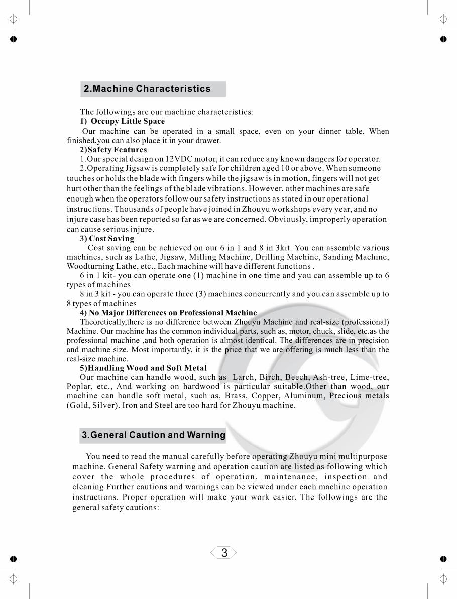
Z002 Z003Z001 Z004
Z006
Z009
Z007 Z008
Z012 Z013
Z010
Z011 Z014
Parts figure

9
Parts figure
Z016Z015Z017 Z018
Z019 Z022
Z023Z020
Z024
Z026
Z027
Z028 Z029 Z030
Z031 Z032
Z025
10
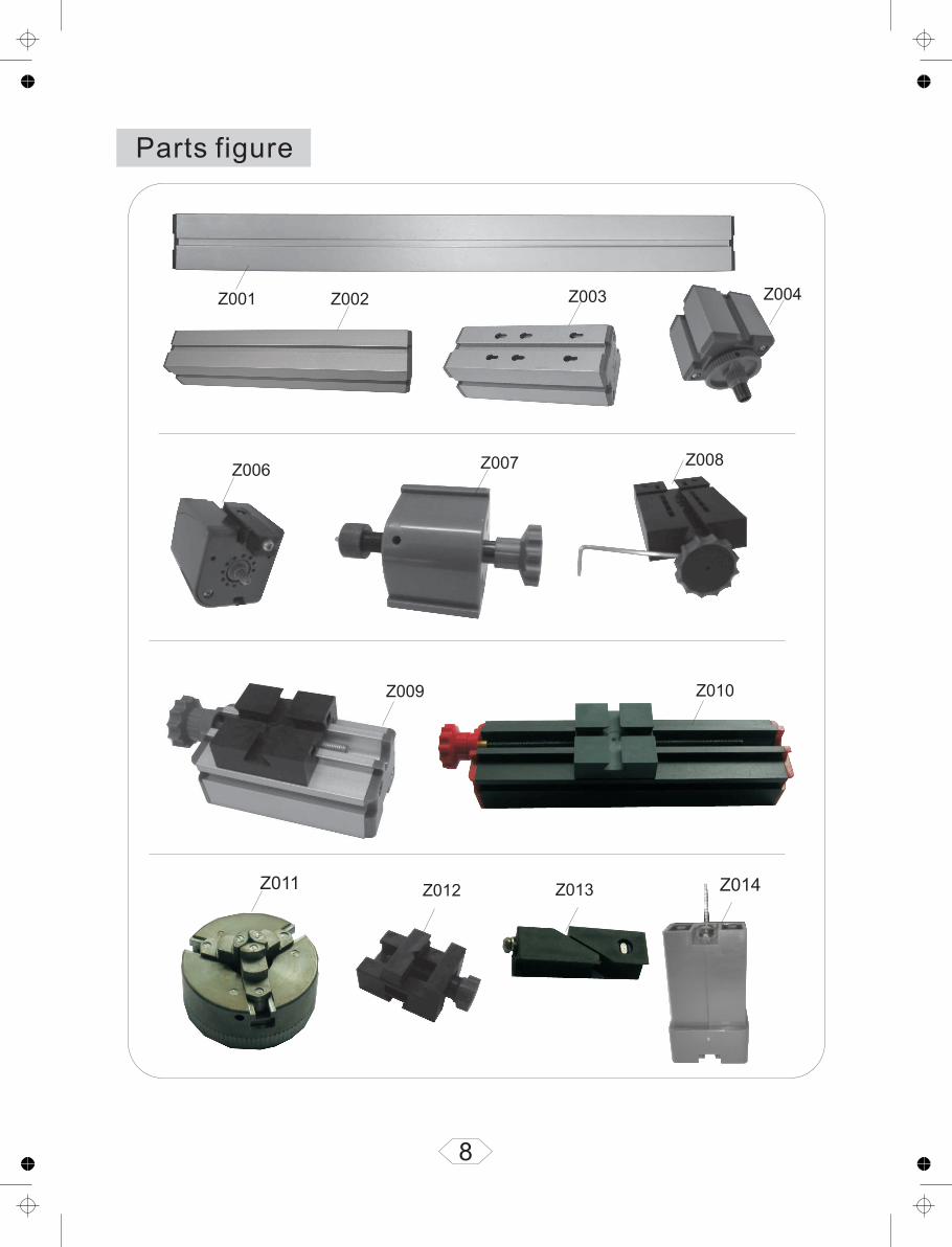
Parts figure
Z033
10
Z034 Z035
Z036 Z039 Z040
Z042 Z043 Z044
Z047Z046
Z045
Z048
Z050
Z049
Z038
11
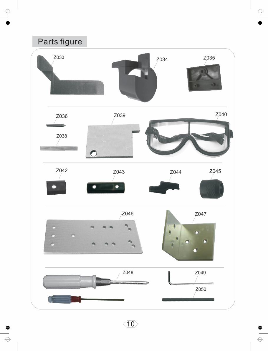
Z051 Z05304Z05201 Z07401 Z07402Z063 Z064
Z06101
Burnish suite(7pcs)
Z06102 Z06103 Z06104
Z06105 Z06106 Z06107 Z06108
Z060
Z06101 φ1mm
Z06102 φ2mm
Z06103 φ2.5mm
Z06104 φ3mm
Z06105 φ3.5mm
Z06106 φ4mm
Z06107 φ5mm
Z06108 φ6mm
Z06201 Cylinder
Z06202 Cone
Z06203 Round ball
Z06204 Disc
Z06205 S em i ci r c le sphere
Z06206 Wool
Z06207 Metal wireZ06201 Z06202 Z06203 Z06204 Z06205 Z06206 Z06207
Z061
Z062
Parts figure
Chuck (8pcs)

12
Z06529 Z06530 Z06527 Z06531 Z06513
Z06511
Screw Standard parts:
Z06504 M3x10 Self tapping screws
Z06508 M3x16
Screw
Z06511 M2x10 Screw
Z06512 M4x7 Screw
Z06513 φ8.8X4.2X0.6 gasket
Z06534 φ12X4.2X0.6 gasket
Z06515 M4x8
Z06516 M4x10
Z06517 M4x12
Z06518 M4x14
Z06519 M4x16
Z06520 M4x25
Z06523 M3x40
Z06527 M3 Six hexagon nut
Z06529 M4 Six hexagon nut
Z06523 Z06520 Z06519 Z06518 Z06517 Z06516 Z06515 Z06504 Z06508
Z06512
Z06534
Z065
Screw
Screw
Screw
Screw
Screw
Screw
Screw

Parts Assembly And Operation
1.Assembly And Operation Of Motor-Wheel Gear Box Unit(Z1):
Fig. 1
Z006
Z004
Z070
Z003101Motor box and connected pieces
Motor and gear box
Tighten screw
Adjust tightness belt
Appropriate belt
Single slot nut
Install the driver belt cover
4×8 nut
The followings are steps for assembling the Motor-Wheel Gear Box Unit(Z1):As shown in Fig 1:
!Connecting Block into the , connect the with the Wheel Gear Box (Z004) by sliding the Connecting Block into the groove of the as shown in Fig.9. Once both the and the Wheel Gear Box are in the corrected position, fasten and tighten the Connecting Block to hold the and the Wheel Gear Box together.
!Fit the toothed belt (Z031) into the Motor and Gear Box. !Finally, the Motor-Wheel Gear Box Unit (Z1) has been assembled. Adjust the belt tension by tightening
or loosening the screw of the motor with a Screwdrivers (Z070) as shown in the diagram. !Ensure the belt having the right tension as the belt has major influence on the motor and work
performance. It is very important for adjusting the tension of the drive belt before starting the motor. !The motor rotating direction is clockwise while face to the motor leaf's slice. !Use the nut and bolt (Z065) to fasten the driver belt cover (Z032) onto the motor to protect the toothed
belt in most situations.
Slide the Dovetail Connecting Block (Z013) into the (Z006).After inserting the Dovetail MotorMotor Motor
Motor Motor Motor
ImportantLoose
13

As shown in Fig :!Hold the Small Slide(Z008) tightly , use the Socket Screw Wrench (Z071) to loosen the bolt in the
position as shown in the diagram.
!Place the other parts of the Small Slide on the base, use the Socket Screw Wrench to tighten the bolt in
the handle. When the above adjustment is done, the Small Slide and the Large Slide Unit (Z2) have
completed as shown in the diagram. !Grease the movable sections as required, such as bolt, dovetail groove of small slide, Large slide, etc.
After that, push the base of small slide out. Slide three Greased Slot
Nuts(Z042) into the dovetail groove of the Large Slide(Z009). Then, fix the Small Slide base on the
Large Slide by tightening the bolts into the three Slot Nuts.
3.Assembly And Operation Of Small Slide(Z008) And Intermediate Piece(Z030) Unit (Z3)
As shown in Fig 3:!
push the base of Small Slide out . !Slide three slot nuts (Z042) into the dovetail groove of the Intermediate Piece (Z030), fix the Small Slide
base on the Intermediate Piece by tightening the bolts into three slot nuts. !Replace the other parts of the Small Slide on the base, tighten the bolt in the handle by Socket Screw
Wrench. !Completing above steps, the Small Slide-Intermediate Piece Unit (Z3) has been assembled as shown in
the diagram. !If you are working with tilted slide, you may need to tighten slide base to the intermediate piece in a
desired angle as shown in the diagram.
Use the Scoket Screw Wrench (Z071) to loosen the bolt in the handle of the Small Slide(Z008). Then,
Z008
Z071
Z042
Z009
Z06515
Tighten screw
Pack small slider Adjust clearance
Adjust clearance
Tighten screw
2.Assembly And Operation Of Small Slide(Z008)And Large Slide(Z009)Unit(Z2)
Fig.2
14
be suitable,or It will influence the precision.
The space must
The space mustbe suitable,or It will influence the precision.
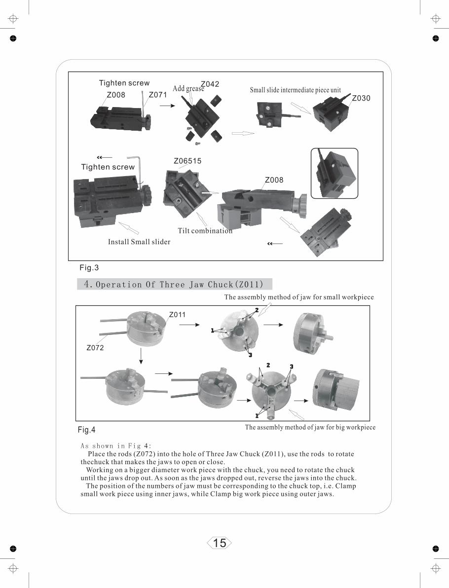
4.Operation Of Three Jaw Chuck(Z011)
As shown in Fig 4: Place the rods (Z072) into the hole of Three Jaw Chuck (Z011), use the rods to rotate thechuck that makes the jaws to open or close. Working on a bigger diameter work piece with the chuck, you need to rotate the chuck until the jaws drop out. As soon as the jaws dropped out, reverse the jaws into the chuck. The position of the numbers of jaw must be corresponding to the chuck top, i.e. Clamp small work piece using inner jaws, while Clamp big work piece using outer jaws.
Z008 Z071
Z042
Z06515
Z030
Z008
Z072
Z011
Tighten screwSmall slide intermediate piece unit
Install Small slider
Tilt combination
The assembly method of jaw for big workpiece
The assembly method of jaw for small workpiece
Tighten screw
Add grease
Fig.3
Fig.4
15
Assembly And Operation of mini Multipurpose Machine
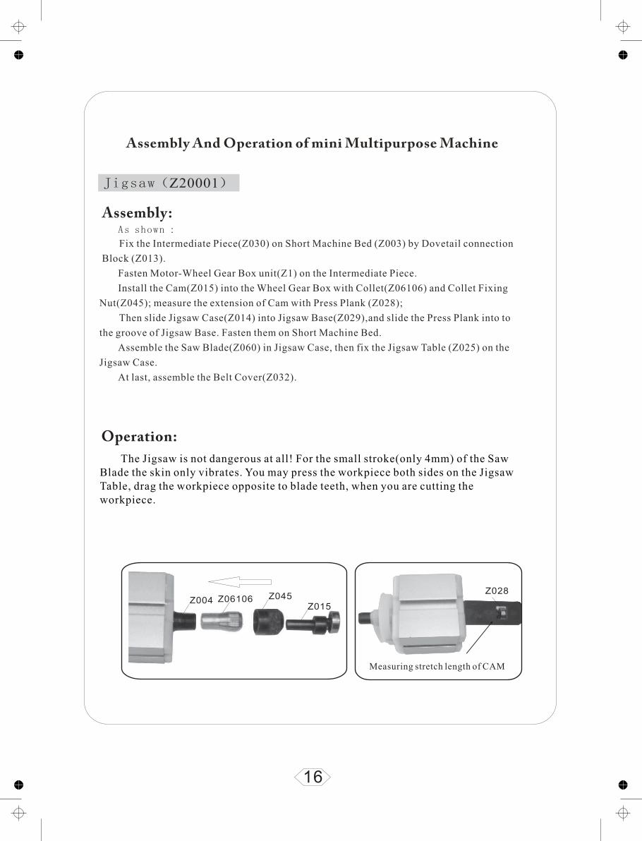
Jigsaw(Z20001)
As shown :
Fix the Intermediate Piece(Z030) on Short Machine Bed (Z003) by Dovetail connection
Block (Z013).
Fasten Motor-Wheel Gear Box unit(Z1) on the Intermediate Piece.
Install the Cam(Z015) into the Wheel Gear Box with Collet(Z06106) and Collet Fixing
Nut(Z045); measure the extension of Cam with Press Plank (Z028);
Then slide Jigsaw Case(Z014) into Jigsaw Base(Z029),and slide the Press Plank into to
the groove of Jigsaw Base. Fasten them on Short Machine Bed.
Assemble the Saw Blade(Z060) in Jigsaw Case, then fix the Jigsaw Table (Z025) on the
Jigsaw Case.
At last, assemble the Belt Cover(Z032).
The Jigsaw is not dangerous at all! For the small stroke(only 4mm) of the Saw Blade the skin only vibrates. You may press the workpiece both sides on the Jigsaw Table, drag the workpiece opposite to blade teeth, when you are cutting the workpiece.
Z004 Z06106 Z045Z015
Z028
Measuring stretch length of CAM
16
Assembly:
Operation:

Z014
Z029 Z070
Z1
Z045
Z013
Z030
Z003
Z029
Z015
Add grease(Vaseline,butter)
Adjust tightness
17
Notice:Once the noise is too load,Check if there is still grease.Grease this place in time to avoid the damage of the machine.
Z060
Z06511
T ighten screw
The method of changing saw blade as shown above.
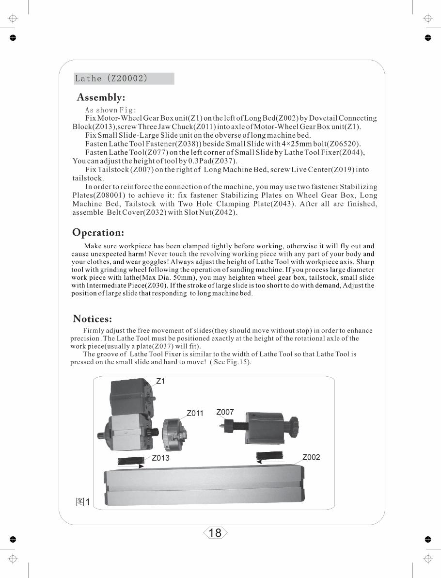
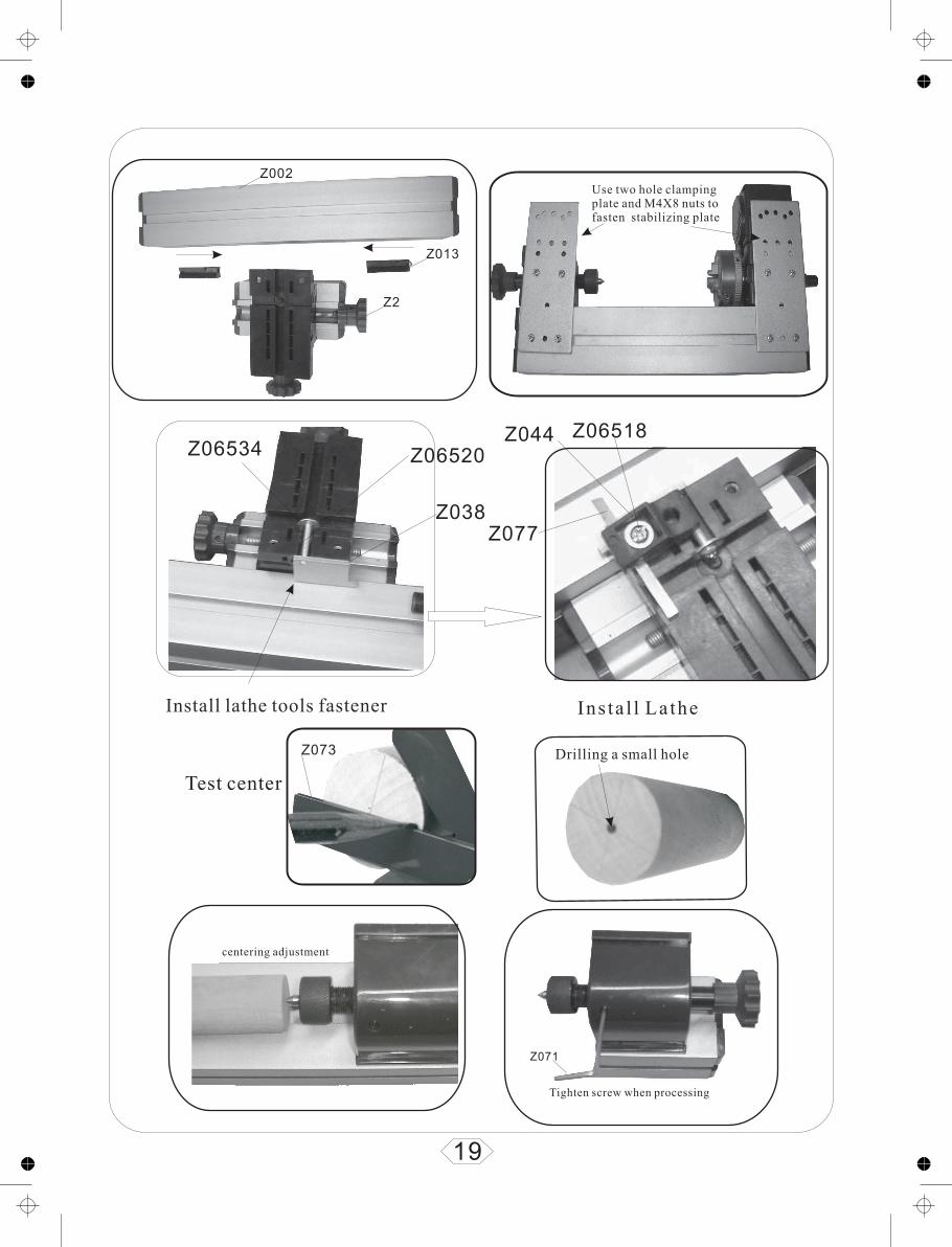
As shown Fig:Fix Motor-Wheel Gear Box unit(Z1) on the left of Long Bed(Z002) by Dovetail Connecting
Block(Z013),screw Three Jaw Chuck(Z011) into axle of Motor-Wheel Gear Box unit(Z1).Fix Small Slide-Large Slide unit on the obverse of long machine bed.Fasten Lathe Tool Fastener(Z038)) beside Small Slide with bolt(Z06520).Fasten Lathe Tool(Z077) on the left corner of Small Slide by Lathe Tool Fixer(Z044),
You can adjust the height of tool by 0.3Pad(Z037).Fix Tailstock (Z007) on the right of Long Machine Bed, screw Live Center(Z019) into
tailstock.In order to reinforce the connection of the machine, you may use two fastener Stabilizing
Plates(Z08001) to achieve it: fix fastener Stabilizing Plates on Wheel Gear Box, Long Machine Bed, Tailstock with Two Hole Clamping Plate(Z043). After all are finished, assemble Belt Cover(Z032) with Slot Nut(Z042).
4×25mm
Make sure workpiece has been clamped tightly before working, otherwise it will fly out and cause unexpected harm! and your clothes, and wear goggles! Always adjust the height of Lathe Tool with workpiece axis. Sharp tool with grinding wheel following the operation of sanding machine. If you process large diameter work piece with lathe(Max Dia. 50mm), you may heighten wheel gear box, tailstock, small slide with Intermediate Piece(Z030). If the stroke of large slide is too short to do with demand, Adjust the position of large slide that responding to long machine bed.
Never touch the revolving working piece with any part of your body
Lathe (Z20002)
Firmly adjust the free movement of slides(they should move without stop) in order to enhance precision .The Lathe Tool must be positioned exactly at the height of the rotational axle of the work piece(usually a plate(Z037) will fit).
The groove of Lathe Tool Fixer is similar to the width of Lathe Tool so that Lathe Tool is pressed on the small slide and hard to move! ( See Fig.15).
18
Z1
Z013
Z011
Z002
图1
Z007
Notices:
Assembly:
Operation:
Z002
Z013
Z2
Use two hole clamping plate and
tabilizing plateM4X8 nuts to
fasten s
19
Z06520Z06534
Z038
Z06518Z044
Z077
Install lathe tools fastener Ins ta l l La the
Z073
Z071
Test center
Drilling a small hole
Tighten screw when processing
centering adjustment

As Shown Fig: Fasten the Drive Center (Z016) into the Wheel Gear Box (Z004) by Collet(Z06106)and Collet
Fixing Nut(Z045),Fix Motor-Wheel Gear Box unit (Z1) on the left of Long Machine Bed (Z002) by Dovetail Connecting Block (Z013).
Fix Small Slide-Large Slide unit (Z2) on the obverse of Long Machine Bed.Fix Woodturning Support(Z033) on the Large Slide (Z009) with Slot Nut(Z042).Fix tailstock (Z007) on the right of Long Machine Bed with Dovetail Connecting Block, screw
LiveCenter (Z019) into tailstock. Use the two fastener Stabilizing Plates (Z08001) to reinforce the connection of the machine on wheel
gear box, long machine bed, tailstock with Two Holes Clamping Plate (Z043). Fasten the Belt Cover (Z032) onto the motor to protect the drive belt in most situations.
Determine the center of round work piece with Center Finder (Z073). Press the Drive Center (Z016) into the center of work piece with a hammer. Use a Dia. 5mm drill bit for the center-hole of the other end (maximum depth 5mm). After assembling the Driver Center and work piece, press Live Center (Z019) with hand, wheel of tailstock against work piece until it is firmed. Tighten tailstock with Socket Screw Wrench (Z071) to avoid work piece dropping out. This will prevent the bolt of tailstock from loosing when it is in motion. Woodturning Support (Z033) should be closed enough to the work piece, but without touching it.Press the Turning Gouge (Z078) on Woodturning Support and hold the handle of the Turning Gouge. Use your right hand holding the handle of the Turning Gouge at the lower position of the Woodturning Support. Move the Turning Gouge to the left and to the right when working. If the stroke of Large Slide is too short to work on, adjust the position of the Large Slide Corresponding to the Long Machine Bed.
Always wear Protective Goggles when working with the machineNever touch the revolving working piece with any part of your body and your clothes.Never hold the handle of the Turning Gouge when it is positioned higher than the Woodturning
Support.
20
Notices:
Operation:
Assembly:
Z004
Z06106
Z1
Z013
Z019
Z007
Z045 Z016
Woodturning Lathe(Z20003)

Woodturning Lathe
Z032
Z06515
Z042
Z071
21
Processing workpiece
Drilling a small hole
Tighten screw when processing
Test center
Centering adjustment
Install a stabilizing plate on gear box and long bed
M4x8 screw
Single slot nut
4x12screw

As Shown Fig: First, screw into Two Hole Clamping Plate(Z043) with two bolts,then slide
the Two Hole Clamping Plate with two bolts into the dovetail groove of Long Machine Bed(Z002), insert the two bolt heads into the pearshaped holes of Short Machine Bed(Z003 )(insert them into bulge-like part of hole, then into neck-like part),firmly tighten screws through Short Machine Bed with Screwdriver(Z070), then place the Long Machine Bed vertically.
Fix the Drilling Table(Z026) on Small Slide-Large Slide unit(Z2) by using two Slot Nuts (Z043) with bolt(Z06518). Fix four Lathe Tool Fixer(Z044) on four corners of the Drilling Table.
Fix Motor-Wheel Gear Box unit(Z1)on Small Slide-Intermediate Piece unit(Z3) with two Dovetail Connecting Blocks(Z013), Fasten the Drilling Bit(Z07401) into the axle of Wheel Gear Box by using Collet(Z06106) and Collet Fixing Nut(Z045),then fix the whole unit on Long Machine Bed.
Turn the handle of Small Slide clockwise until stop, loosen Socket Screw on the handle with Socket Screw Wrench(Z071) until the handle can be moved free from the bolt axle of Small Slide,Stick on Drilling Lever (Z027) between the hole of Intermediate Piece and Small Slide. You may drive the Drilling Lever up and down while working.
4X7 (Z06515) 4X6
4×12
Drilling Machine(Z20004)
Z002
Z003Z042
Z002
Z003
Tighten screwTwo clamping plateTwo clamping plate
Install right angle stabilizing plate
4x8screw
22
As the stroke of Drilling Lever is limited, you may adjust the position of Intermediate Piece responding to Long Machine Bed with regarding to different working depth and work piece. Different drilling bits for different collets. Adjust the position of large slide responding to long machine bed if the stroke of large slide can not meet the working requirement. By tilting small slide, work piece can be drilled at some angle(See Fig )
Always wear Protective Goggles Never touch the revolving with any part of your body Never touch the revolving
when working.Drilling Bit and your clothes.Drive Belt and Gear as the Drive Belt Cover is not assembled
on the Motor-Wheel Gear Box unit(Z1) regarding drilling machine.
Operation:
Assembly:

23
Fig.20
Z044
Z06517
Z026
Z2
Z1 Z3
Z013
Z004 Z06105
Z045
Z07401
Screw3×16
Remarks:According to yourse lf need to choose whether to add lathe tool fixer.
Notice:When you use drilling lever, please loosen the screw.
Drilling Machine(Z20004)
Z002
Z013

As Shown Fig:Screw and slide the two 4x7 Bolts (Z06515) into Two Hole Clamping Plate (Z043)
and the dovetail groove of the Long Machine Bed (Z002) respectively. Insert the two bolt heads into the pear-shaped holes of Short Machine Bed (Z003).
The insertion must be straight through the bulge-like part of hole into the neck-like part. Tighten the screws firmly with Screwdriver(Z070). Hold the Long Machine Bed horizontally. Fasten the Small Slide-Intermediate Piece unit (Z3) onto the Small Slide vertically with
the Dovetail Connecting Block (Z013). Fasten the Milling Tool (Z07501) into the axle of Wheel Gear Box by using Collet (Z06104) and
Collet Fix Nut (Z045). Ensure the whole unit(Z1) fix on the Small Slide-Intermediate Piece unit firmly.Connect the machine Vice (Z012) to the Small Slide-Large Slide(Z2) unit with Dovetail
Connecting Block. Connect the Small Slide-Large Slide unit to the Long Machine Bed obverse with Dovetail Connecting Block.
Always wear Protective Goggles(Z040) when operating the machine.Never touch the revolving working piece with any part of your body and your clothes.Be aware of the danger of the Milling Tool as the Bit is very sharp.
24
Adjust the position of the Intermediate Piece in corresponding to the Long Machine Bed to accommodate different working depth and the height of the work piece.
Use different Milling Tool bits with different Collets (Z061) When the stroke of the Large Slide is insufficient, adjust the position of the Large Slide in
corresponding to the Long Machine Bed. By tilting Small Slide, work piece can be milled at some angle as shown in the diagram. And
also can assemble this machine into vertical milling machine referring to the assembling of drilling machine.
You can process dividing with the Three-jaw Chuck(Z011) ,Dividing Positioner(Z022) and Dividing Attachment(Z023).
Milling Machine (Z20005):
Operation:
Assembly:
Notices:
Z002
Z003Z042
Z002
Z003
Tighten screwTwo clamping plateTwo clamping plate
Install right angle stabilizing plate
4x8screw

Oblique milling)drilling( Horizontal milling machine
Vertical milling machine
Install right angle stabilizing plate
When you use lever, Please loosen the screw.
25
Lever
Z2
Z013
Z012
Z0
04
Z0
61
08
Z0
45
Z0
75
01
Z002
Z013
Z009

Sanding Machine(Z20006):
As hown Fig: s Connect the Motor-Wheel Gear Box Unit (Z1) to the left of Long Machine Bed (Z002) with Dovetail Connecting Block(Z013).
Adhere the Sanding paper (Z024)(with pressure-sensitive adhesive in the back) to the Clamping Plate (Z017).
Screw the Clamping Plate into the Axle of Wheel Gear Box(Z004).Use the Slot Nut (Z042) to connect the Drilling Table (Z026) to the top of the Long Machine Bed
near to the Sanding Paper.Adhere the Grinding Wheel(Z01801) on the Grinding Wheel Assy(Z01802). Insert the Grinding Wheel and its accessories into the end of the Axle of Wheel Gear Box .Ensure
the flange of Grinding Wheel Assy corresponds to the groove of Wheel Gear Box .Connect the Grinding Wheel Cover(Z034) to the Grinding Wheel Cover Connection (Z035) with
two 3x10 Bolts (Z06504). Install the unit on Wheel Gear Box with Slot Nut(Z042).
Ensure the Tools to be sanded aligns with the axis of grinding wheel while grinding.Sand workpiece with sanding paper adhering.Observe the direction of workpiece movement and it must be opposite towards
Rotating direction of grinding wheel.
Always wear Protective Goggles(Z040) when working with the machine.Never touch the revolving working piece with any part of your body and your clothes.Never dismantle Grinding Wheel Cover for avoiding accidents while working.
26
Assembly:
Operation:
Notices:
Z1
Z017Z026
Z06518Z042Z013
Z01801
Z002
Z01802
Grinding Tools
Z034Z06504
Z070
Z035
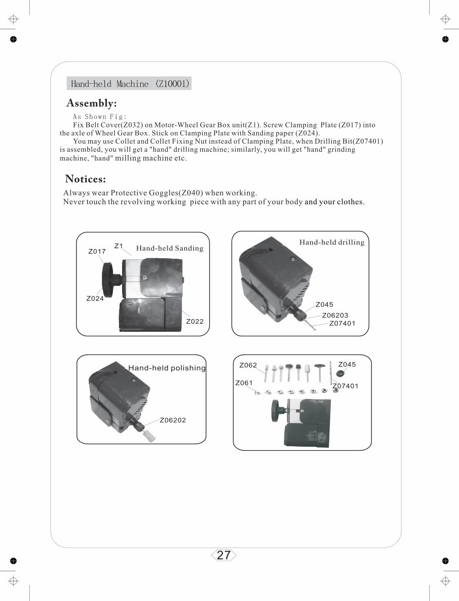
Hand-held Machine (Z10001)
Always wear Protective Goggles(Z040) when working.Never touch the revolving working piece with any part of your body and your clothes.
As Shown Fig: Fix Belt Cover(Z032) on Motor-Wheel Gear Box unit(Z1). Screw Clamping Plate (Z017) into
the axle of Wheel Gear Box. Stick on Clamping Plate with Sanding paper (Z024). You may use Collet and Collet Fixing Nut instead of Clamping Plate, when Drilling Bit(Z07401)
is assembled, you will get a "hand" drilling machine; similarly, you will get "hand" grinding machine, "hand" milling machine etc.
Hand-held Sanding
27
Z1Z017
Z024
Z022 Z07401Z06203
Z045
Z06202
Z061
Z062
Z07401
Z045Hand-held polishing
Hand-held drilling
Assembly:
Notices:
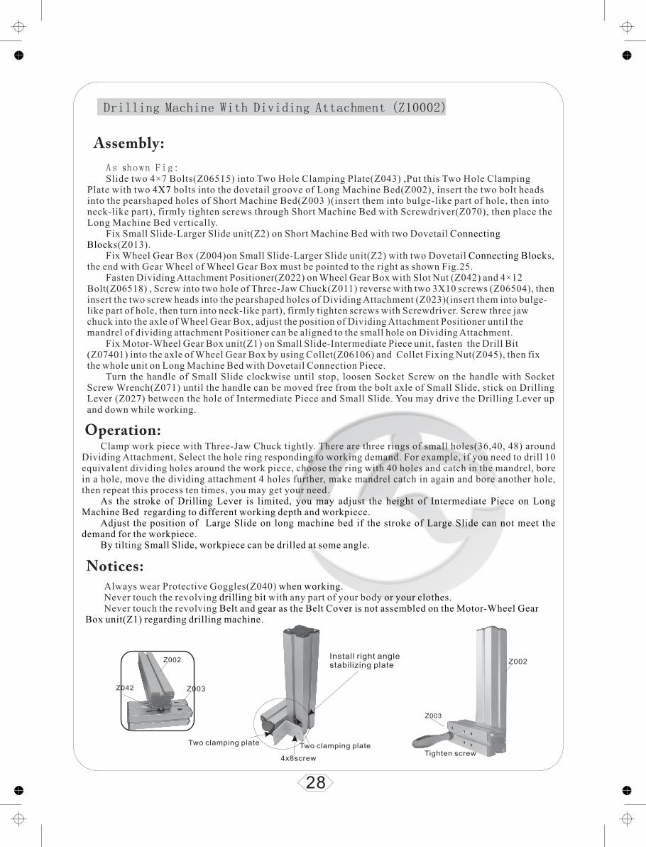
Drilling Machine With Dividing Attachment (Z10002)
Clamp work piece with Three-Jaw Chuck tightly. There are three rings of small holes(36,40, 48) around Dividing Attachment, Select the hole ring responding to working demand. For example, if you need to drill 10 equivalent dividing holes around the work piece, choose the ring with 40 holes and catch in the mandrel, bore in a hole, move the dividing attachment 4 holes further, make mandrel catch in again and bore another hole, then repeat this process ten times, you may get your need.
ing
As the stroke of Drilling Lever is limited, you may adjust the height of Intermediate Piece on Long Machine Bed regarding to different working depth and workpiece.
Adjust the position of Large Slide on long machine bed if the stroke of Large Slide can not meet the demand for the workpiece.
By tilt Small Slide, workpiece can be drilled at some angle.
As shown Fig: Slide two 4×7 Bolts(Z06515) into Two Hole Clamping Plate(Z043) ,Put this Two Hole Clamping
Plate with two bolts into the dovetail groove of Long Machine Bed(Z002), insert the two bolt heads into the pearshaped holes of Short Machine Bed(Z003 )(insert them into bulge-like part of hole, then into neck-like part), firmly tighten screws through Short Machine Bed with Screwdriver(Z070), then place the Long Machine Bed vertically.
Fix Small Slide-Larger Slide unit(Z2) on Short Machine Bed with two Dovetail s(Z013).
Fix Wheel Gear Box (Z004)on Small Slide-Larger Slide unit(Z2) with two Dovetail s, the end with Gear Wheel of Wheel Gear Box must be pointed to the right as shown Fig.25.
Fasten Dividing Attachment Positioner(Z022) on Wheel Gear Box with Slot Nut (Z042) and 4×12 Bolt(Z06518) , Screw into two hole of Three-Jaw Chuck(Z011) reverse with two 3X10 screws (Z06504), then insert the two screw heads into the pearshaped holes of Dividing Attachment (Z023)(insert them into bulge-like part of hole, then turn into neck-like part), firmly tighten screws with Screwdriver. Screw three jaw chuck into the axle of Wheel Gear Box, adjust the position of Dividing Attachment Positioner until the mandrel of dividing attachment Positioner can be aligned to the small hole on Dividing Attachment.
Fix Motor-Wheel Gear Box unit(Z1) on Small Slide-Intermediate Piece unit, fasten the Drill Bit (Z07401) into the axle of Wheel Gear Box by using Collet(Z06106) and Collet Fixing Nut(Z045), then fix the whole unit on Long Machine Bed with Dovetail Connection Piece.
Turn the handle of Small Slide clockwise until stop, loosen Socket Screw on the handle with Socket Screw Wrench(Z071) until the handle can be moved free from the bolt axle of Small Slide, stick on Drilling Lever (Z027) between the hole of Intermediate Piece and Small Slide. You may drive the Drilling Lever up and down while working.
4X7
Connecting Block
Connecting Block
Always wear Protective Goggles(Z040) .Never touch the revolving with any part of your body Never touch the revolving
when workingdrilling bit or your clothes.
Belt and gear as the Belt Cover is not assembled on the Motor-Wheel Gear Box unit(Z1) regarding drilling machine.
28
Assembly:
Operation:
Notices:
Z002
Z003Z042
Z002
Z003
Tighten screwTwo clamping plateTwo clamping plate
Install right angle stabilizing plate
4x8screw

Z022Z06518
Z004
Z013
Z2
Z027
Slot nut
use drilling lever, Please loosen the screw.
29
Drilling Machine With Dividing Attachment (Z10002)
Z070
Z06504Z011
Z023
Z002
Z013
Z009
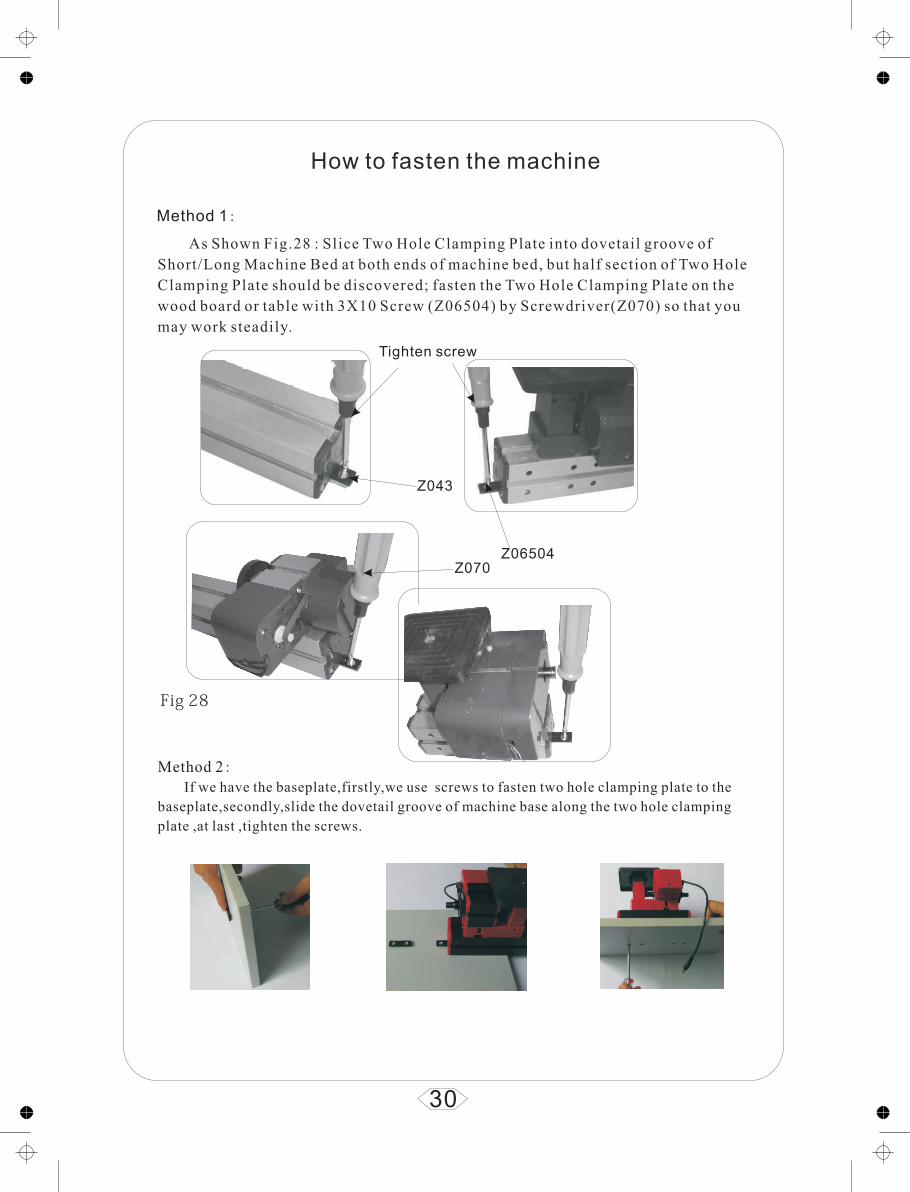
How to fasten the machine
Method 1:
Z043
Z06504Z070
Tighten screw
30
Method 2:If we have the baseplate,firstly,we use screws to fasten two hole clamping plate to the
baseplate,secondly,slide the dovetail groove of machine base along the two hole clamping
plate ,at last ,tighten the screws.
Fig 28

Important Data
Description Important Data
Power Adaptor
Prim.Input Voltage:220V~240V,50~60Hz/110V~120V,50Hz~60Hz
Sek.Output Voltage:12V DC, Power Supply:24W Direct Current :2A,
With thermostat protector
Motor
12V DC,Power input up to 2A. Current/Power Supply:500mA/6W
Speed of high speed motor up to 20,000 rpm
Speed of Low speed motor up to 12,000 rpm
Motor Leaf's slice gear rim: 10 teeth
Wheel Gear Box
Axle Nose: M12X1
Hole Through Axle:8mm
Wheel Gear Box gear rim: 23 teeth /60 teeth
Bearing:Ball Bearing
Tailstock Axle Nose:M12X1,Travel of tailstock: 15mm
Machine Vice Clamping Capacity: 25X35mm
Small/Large Slide
One turn with the handle is 1mm feed
Trave l of small slide:30m m
Travel of large slide:50mm
31

Description Important Data
JigsawStroke of saw blade: 4 mm
Material and max.depth of cut:balsa18mm,plywood7mm,hard wood 4 mm , plexi -glass 2 mm , aluminium plate 1 mm
Lathe
Center height from the machine bed : 25mm , (with intermediatepiece can be heighten to50mm )
Center distance : 135mm , (with extra long machine bed can be longer to365mm )
Max .cutting diameter : 20mm (bigger diameter up to 50mm is possible with intermediate piece )
Material of turning:any kind of wood (hard wood will be better ) Sof t metal(such as gold , silver,aluminium etc.)
Woodturning lathe
Center height from the machine bed : 25 mm , (with intermediate piece can be heighten to50mm )
Center distance:135mm , (with extra long machine bed can be longer to 365mm )
Max cutting diameter,(bigger diameter up to 50 mm is possible with intermediate piece )
Material of turning : any kind of wood (hard wood will be better )
Drilling Machine
Travel of drilling lever: 25mm
Drilling table size: 123 100mm×
Collet clamping size for drill bit: 1mm,2mm,2.5mm,3mm,3.5mm,4mm,5mm,6mm .
Material of drilling:any kind of wood (hard wood will be better ) Soft metal(such as gold , silver,aluminum etc.)
Milling Machine
Collet clamping size for milling cutter: 1mm ,2mm,2.5mm,3mm,3.5mm,4mm,5mm,6mm.
Material of milling : any kind of wood (hard wood will be better )Soft metal(such as gold , silver,aluminium etc.)
Sanding Machine
Clamping plate size: Dia.50mm
Drilling table size : 123×100mm
Grain of sanding paper :100 # or choose other you need
Material of sanding:any kind of wood (hard wood will be better ) Soft metal(such as gold , silver,aluminium etc.)
32
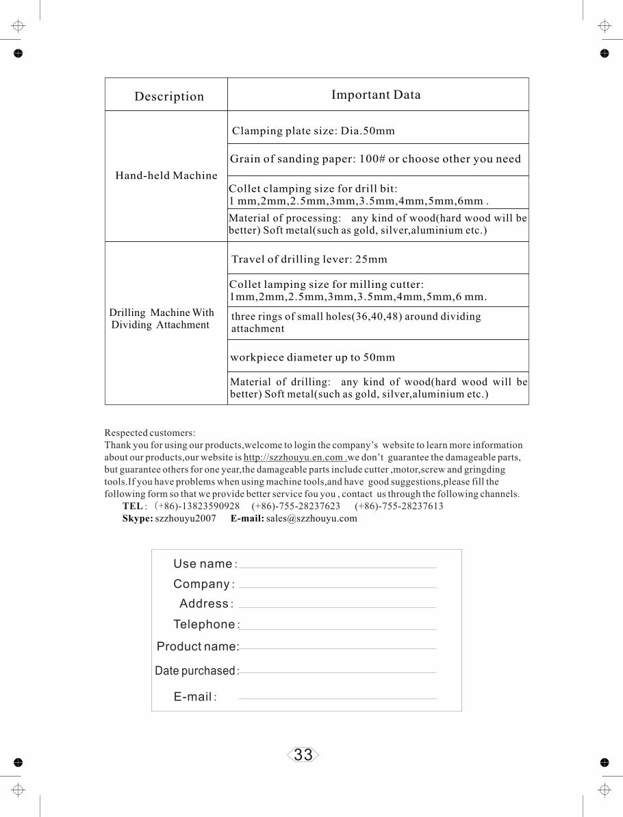
Description Important Data
Hand-held Machine
Clamping plate size: Dia.50mm
Grain of sanding paper: 100# or choose other you need
Collet clamping size for drill bit: 1 mm,2mm,2.5mm,3mm,3.5mm,4mm,5mm,6mm .
Material of processing: any kind of wood(hard wood will be better) Soft metal(such as gold, silver,aluminium etc.)
Travel of drilling lever: 25mm
Collet lamping size for milling cutter: 1mm,2mm,2.5mm,3mm,3.5mm,4mm,5mm,6 mm.
three rings of small holes(36,40,48) around dividing attachment
workpiece diameter up to 50mm
Material of drilling: any kind of wood(hard wood will be better) Soft metal(such as gold, silver,aluminium etc.)
Drilling Machine With Dividing Attachment
Use name:
Address:
Telephone:
E-mail:
Product name:
Date purchased:
33
Respected customers:Thank you for using our products,welcome to login the company’s website to learn more information about our products,our website is http://szzhouyu.en.com .we don’t guarantee the damageable parts, but guarantee others for one year,the damageable parts include cutter ,motor,screw and gringding tools.If you have problems when using machine tools,and have good suggestions,please fill the following form so that we provide better service fou you , contact us through the following channels.
TEL:(+86)-13823590928 (+86)-755-28237623 (+86)-755-28237613Skype: szzhouyu2007 E-mail: [email protected]
Company:
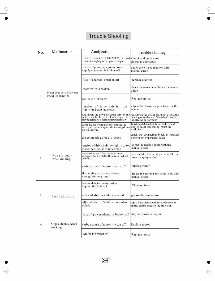
Trouble Shooting
No. Malfunction Analyzation Trouble Shooting
Motor does not work when power is connected
Check and make sure power is connected
P o w e r s o c k e t ( 11 0 / 2 2 0 V ) i s n o t connected rightly or no power output
socket of power apaptor or power supply connector is broken off
check the wire connection with manual guide
1
fuse of adaptor is broken off replace adaptor
motor wire is brokencheck the wire connection with manualguide
Motor is broken off Replace motor
tension of dr ive bel t is too tightly,and stop the motor
take down the drive belt,then turn on the motor switch; the axle of wheel gear box maybe get stuck if the motor run normally
adjust the tension again base on the manaul
take down the wheel gear box, grease the bearing or replace it if the wheel gear box is not rotating normally
see if it does not run after clamping the workpiece, check again after taking down the workpiece
Tension of drive belt is too tightly,and stop; or see if some thing resist the workpiece
2Noise is loudly when running
the connecting block is loosencheck the is screwed tighly or not with manaul guide
connecting block
tension of drive belt too tightly or tooloosen will cause loudly noise
adjust the tension again with the manual guide
maybe the axes of workpiece is notsuperposition with the the axes of wheel gear box
reassemble the workpiece until the axes is superposition
carbon brush of motor is worn off replace motor
the moving parts is not greased enough for long time
grease the moving parts right now with manual guide
3 Feed back hardly
Accumulate too many dust to Support the feedback Clean on time
screw of slide is seldom greased grease the connection
adjustable bolt of slide is screwed too tightly
adjust base on manual, for too loosen or tightly can be effected the precision
4 Stop suddenly whenworking
fuse of power adaptor is broken off Replace power adaptor
carbon brush of motor is worn off Replace motor
Motor is broken off Replace motor
34

No. Malfunction Analyzation Trouble Shooting
Jigsaw is cutting hardly5
6
7
8
read the concerned pages in manualcarefully before working
working piece too thick or improperforce direction
forward direction of working piece isnot right towards the saw blade teeth
read the concerned pages in manual carefully before working
belt is worn out for long time working replace the belt
cam is worn out replace the cam
the axle of jigsaw case is worn outmaintain or replace the axle of jigsaw case
saw blade is worn off for long time cutting replace the saw blade
Saw blade is brokenimproper force direction or saw blade is assembled loose
See the manual, reassemble the saw blade,(saw blade is used up to 3 times)
Turning Hardly in lathe
feed back too fastfeed back slowly for beginner until you get more experience, different material for different feedback.
knifepoint of tool is not positioned atthe rotation center of work piece
adjust the height of tool until the knifepoint is positioned at the rotation center of work piece.
turning tool is not sharpoften sharp the tool and sharp the right angles of tool-edge
Belt is worn out for long time working replace the belt
axle of tailstock or live center is loosen
adjust the position of tailsock and livecenter in the right way (see the manual), screw the bolt of tailstock tightly
Turning hardly in woodturning lathe
feed back too fast
knifepoint of gouge is not positionedat the rotation center of work piece
gouge is not sharp
drive belt is worn out for long time working
axle of tailstock or live center is loosen
feed back slowly for beginner until you get more experience, different material for different feedback.
place the gouge on the woodturningsupport,knifepoint of tool is position at the rotation center of work piece
often sharp the tool and sharp the right angles of tool-edge
replace the drive belt
adjust the position of tailsock and livecenter in the right way (see the manual), screw the bolt of tailstock tightly
35

Instancing models
36

37