穨 amb2003-23-53 manual v1€¦ · chapter 1 general information amb-2003/2023/2053 user’s...
TRANSCRIPT

AMB-2003/2023/2053 User’s Manual
AMB-2003/2023/2053 Series Modular System Industrial Panel PCs
Version 1.0
Industrial Panel PCs Industrial Panel PCs for Industrial Automation
User’s Manual
AMB-2003/2023/2053 User’s Manual 2
Contents Chapter1 General Information.......................................... 1
1.1 Introduction................................................. 2 1.2 Specifications ............................................... 3
General............................................................................................3 Environmental................................................................................3 Rear View picture...........................................................................3 Features ..........................................................................................4 Specifications.................................................................................6 Power Supply Selection Table.....................................................8
1.3 Touchscreen (Optional) .............................. 9 1.4 Order Information..................................... 10 1.5 LCD Specifications .................................... 11 1.6 Dimensions ................................................ 12 1.7 Panel Mounting ......................................... 15 1.8 Packing List .............................................. 16
Chapter2 MBC-6310 Introduction.................................. 14
Checklist ................................................................... 15 Description................................................................ 16 Features .................................................................... 17 Specifications ............................................................. 18 Intelligence ............................................................... 20 Board Dimensions..................................................... 21
Chapter3 MBC-6310 Installations .................................. 22
CPU Installation........................................................ 23 Memory Installation.................................................. 24 Jumpers on the MBC-6310...................................... 25
Jumper Locations on the MBC-6310 ........................................26 DSW1 (1-8): CPU Frequency Selector......................................27 JP1: DiskOnChip BIOS Expansion Address Select ................28 JP2: Clear CMOS Content ..........................................................29 JP4: LCD Power Setting..............................................................29 Setting...........................................................................................29
Connectors on the MBC-6310 ................................. 30 Connector Locations on the MBC-6310 ..................................31 J1, J2: EIDE Connectors..............................................................32

AMB-2003/2023/2053 User’s Manual 3
J3: Front Bezel Connector..........................................................33 JP3: IrDA Connector...................................................................35 J4: Floppy Drive Connector.......................................................36 J5: Parallel Port Connector.........................................................36 J6: External Keyboard Connector..............................................37 J7, J8: COM1/COM2 Serial Ports...............................................37 J9: PS/2 Keyboard Connector....................................................37 J10: PS/2 Mouse Connector.......................................................38 J11: VGA CRT Connector...........................................................38 J12: RJ45 Connector....................................................................38 J13: External ATX Power Connector........................................40 J14, J15: LCD Panel Connectors ................................................40 Flat Panel Display Interface Pin Descriptions.........................41 J17, J18: USB Connectors...........................................................42 J20: CPU Fan Power Connector.................................................42 J21: Chassis Fan Power Connector...........................................42
Watchdog Timer Configuration ................................ 43 Exploded Diagram..................................................... 44 Cooling Fan Replacement......................................... 45 Install a 3.5” HDD .................................................... 46 Install a Slim CD-Rom, FDD and 2.5” HDD ............ 47

Chapter 1 General Information
AMB-2003/2023/2053 User’s Manual 1
1 Chapter1 General Information
1.1 Introduction................................................. 2 1.2 Specifications ............................................... 3 1.3 Touchscreen (Optional) .............................. 9 1.4 Order Information..................................... 10 1.5 LCD Specifications .................................... 11 1.6 Dimensions ................................................ 12 1.7 Panel Mounting ......................................... 15 1.8 Packing List .............................................. 16

Chapter 1 General Information
AMB-2003/2023/2053 User’s Manual 2
1.1 Introduction
The AMB-2003/2023/2053 series modular system panel PCs, is the PC-base industrial computer that specially designed to keep normal operation under harsh environment, which meet the entire requirement as an industrial man machine interface (MMI).
They provide a complete hard ware application and construct a high quality plastic front panel NEMA 4/12 which meets the toughest industrial and environmental protection standards
It is a full-function PC-base system with a 10.4” VGA(640 x 480), 12.1” SVGA (800 x 600), 15.1” XGA (1024 x 768) color TFT hi-brightness, long-life time LCD display, and compact with different control modules via a 50-pin SCSI cable. The compact dimensions are ideal for automation applications when the installation space is critical.
These PCs are characterized by their space saving, there are two free slots for PCI/ ISA. AMB-2003/2023/2053 is heavy-duty steel chassis with a sealed plastic front panel. meets the toughest industrial and environmental standards. All the controls and connectors are placed on the rear panel, you can connect the panel PCs to other devices via them.
Chapter 1 General Information
AMB-2003/2023/2053 User’s Manual 3
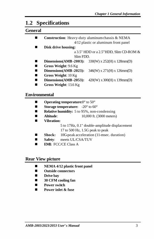
1.2 Specifications General
n Construction: Heavy-duty aluminum chassis & NEMA 4/12 plastic or aluminum front panel
n Disk drive housing: a 3.5" HDD or a 2.5”HDD, Slim CD-ROM & Slim FDD.
n Dimensions(AMB -2003): 330(W) x 252(H) x 128mm(D) n Gross Weight: 9.6 Kg n Dimensions(AMB -2023): 346(W) x 271(H) x 126mm(D) n Gross Weight: 10 Kg n Dimensions(AMB -2053): 420(W) x 300(H) x 139mm(D) n Gross Weight: 13.6 Kg
Environmental
n Operating temperature:0° to 50° n Storage temperature: -20° to 60° n Relative humidity: 5 to 95%, non-condensing n Altitude: 10,000 ft. (3000 meters) n Vibration:
5 to 17Hz, 0.1" double-amplitude displacement 17 to 500 Hz, 1.5G peak to peak
n Shock: 10G-peak acceleration (11-msec. duration) n Safety: meets UL/CSA/TUV n EMI: FCC/CE Class A
Rear View picture
n NEMA 4/12 plastic front panel n Outside connectors n Drive bay n 30 CFM cooling fan n Power switch n Power inlet & fuse
Chapter 1 General Information
AMB-2003/2023/2053 User’s Manual 4
Features
AMB-2003 (10.4”LCD + ACS-2303 Control Box) n 10.4” VGA color TFT LCD display n Heavy-duty steel chassis and NEMA 4/12
compliant plastic front panel n All-in-one SBC, Intel Celeron 366MHz CPU, 32MB
SDRAM, Ethernet, VGA. n Two 16C550 RS-232C port, two RS-232C port n Disk Driver Space for CD-ROM, FDD and HDD n DiskOnChip flash disk socket n Print Port n Expansion IDE/Floppy connectors*** n Touch Screen (optional) n USB port (optional)
***Expansion IDE port will not functional when both HDD & CD-ROM install in the machine
AMB-2023 (12.1”LCD + ACS-2303 Control Box) n 12.1” SVGA color TFT LCD display n Heavy-duty steel chassis and NEMA 4/12
compliant plastic front panel n All-in-one SBC, Intel Celeron 366MHz CPU, 32MB
SDRAM, Ethernet, VGA. n Two 16C550 RS-232C port, two RS-232C port n Disk Driver Space for CD-ROM, FDD and HDD n DiskOnChip flash disk socket n Print Port n Expansion IDE/Floppy connectors*** n Touch Screen (optional) n USB port (optional)
***Expansion IDE port will not functional when both HDD & CD-ROM install in the machine
Chapter 1 General Information
AMB-2003/2023/2053 User’s Manual 5
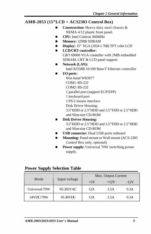
AMB-2053 (15”LCD + ACS-2303 Control Box) n 15” XGA color TFT LCD display n Heavy-duty steel chassis and NEMA 4/12
compliant plastic front panel n All-in-one SBC, Intel Celeron 366MHz CPU, 32MB
SDRAM, Ethernet, VGA. n Two 16C550 RS-232C port, two RS-232C port n Disk Driver Space for CD-ROM, FDD and HDD n DiskOnChip flash disk socket n Print Port n Expansion IDE/Floppy connectors n Touch Screen (optional) n USB port (optional)
***Expansion IDE port will not functional when both HDD & CD-ROM install in the machine

Chapter 1 General Information
AMB-2003/2023/2053 User’s Manual 6
Specifications
AMB-2003 (10.4”LCD + ACS2303 Control Box) n Construction: Heavy-duty steel chassis &
NEMA 4/12 plastic front panel. n CPU: Intel Celeron 366MHz n Memory: 32MB SDRAM n Display: 10.4” VGA (640 x 480) TFT color LCD n LCD/CRT controller:
C&T 69000 VGA controller with 2MB embedded SDRAM. CRT & LCD panel support
n Network (LAN): Intel 82558B 10/100 Base-T Ethernet controller
n I/O ports: Win bond W83977 COM1: RS-232 COM2: RS-232 1 parallel port (support ECP/EPP) 1 keyboard port 1 PS/2 mouse interface Disk Driver Housing: 3.5”HDD or 2.5”HDD and 3.5”FDD or 2.5”HDD and Slim-size CD-ROM
n USB connector: Dual USB ports onboard n Mounting: Panel mount or Wall mount (ACS-2303
Control Box only, optional) n Power supply: Universal 70W switching power
supply

Chapter 1 General Information
AMB-2003/2023/2053 User’s Manual 7
AMB-2023 (12.1”LCD + ACS2303 Control Box) n Construction: Heavy-duty steel chassis &
NEMA 4/12 plastic front panel. n CPU: Intel Celeron 366MHz n Memory: 32MB SDRAM n Display: 12.1” SVGA (800 x 600) TFT color LCD n LCD/CRT controller:
C&T 69000 VGA controller with 2MB embedded SDRAM. CRT & LCD panel support
n Network (LAN): Intel 82558B 10/100 Base-T Ethernet controller
n I/O ports: Win bond W83977 COM1: RS-232 COM2: RS-232 1 parallel port (support ECP/EPP) 1 keyboard port 1 PS/2 mouse interface Disk Driver Housing: 3.5”HDD or 2.5”HDD and 3.5”FDD or 2.5”HDD and Slim-size CD-ROM
n USB connector: Dual USB ports onboard n Mounting: Panel mount or Wall mount (ACS-2303
Control Box only, optional) n Power supply: Universal 70W switching power
supply
Chapter 1 General Information
AMB-2003/2023/2053 User’s Manual 8
AMB-2053 (15”LCD + ACS2303 Control Box) n Construction: Heavy-duty steel chassis &
NEMA 4/12 plastic front panel. n CPU: Intel Celeron 366MHz n Memory: 32MB SDRAM n Display: 15” XGA (1024 x 768) TFT color LCD n LCD/CRT controller:
C&T 69000 VGA controller with 2MB embedded SDRAM. CRT & LCD panel support
n Network (LAN): Intel 82558B 10/100 Base-T Ethernet controller
n I/O ports: Win bond W83977 COM1: RS-232 COM2: RS-232 1 parallel port (support ECP/EPP) 1 keyboard port 1 PS/2 mouse interface Disk Driver Housing: 3.5”HDD or 2.5”HDD and 3.5”FDD or 2.5”HDD and Slim-size CD-ROM
n Disk Driver Housing: 3.5”HDD or 2.5”HDD and 3.5”FDD or 2.5”HDD and Slim-size CD-ROM
n USB connector: Dual USB ports onboard n Mounting: Panel mount or Wall mount (ACS-2303
Control Box only, optional) n Power supply: Universal 70W switching power
supply.
Power Supply Selection Table
Max. Output Current Mode Input voltage
+5V +12V -12V
Universal/70W 85-265VAC 12A 2.5A 0.3A
24VDC/70W 10-30VDC 12A 2.5A 0.3A

Chapter 1 General Information
AMB-2003/2023/2053 User’s Manual 9
1.3 Touchscreen (Optional) l Type: 4/8-wire, analog resistive l Resolution: Continuous l Light transmission: 72% (surface 4H, meets
ASTM-D-3363-92A standard.) l Operating pressure: <50 grams for finger, <25 grams
for stylus pen. Contact bounce< 10ms l Controller: RS-232 interface l Power consumption: +5V @200mA l OS support: MS DOS, Windows 3.1, Windows 95,
Windows 98, Windows NT, Windows2000
Chapter 1 General Information
AMB-2003/2023/2053 User’s Manual 10
1.4 Order Information AMB-2003HT:
10.4” Modular system Industrial Panel PC
AMB-2003HTT: AMB-2003HT with touchscreen
AMB-2023HT: 12.1” Modular system Industrial Panel PC
AMB-2023HTT:
AMB-2023HT with touchscreen AMB-2053HT:
15” Modular system Industrial Panel PC
AMB-2053HTT: AMB-2053HT with touchscreen
Chapter 1 General Information
AMB-2003/2023/2053 User’s Manual 11
1.5 LCD Specifications
Model AMB-2003 AMB-2023 AMB-2053
Display type Color TFT LCD Color TFT LCD Color TFT LCD
Size (diagonal)
10.4” 12.1” 15”
Number of Pixels
640(W) x 480(H) 800(W) x 600(H) 1024(W) x 768(H)
Dot size (mm x mm)
0.33(W) x 0.33 0.3075(W) x 0.3075 0.313(W) x 0.329(H)
Contrast ratio
250 250 300
View angle (Horizontal)
90° 120° 160°
View angle (Vertical)
50° 100° 160°
Luminance (cd/m2 )
200 250 250
LCD model NEC
AC33-18 Toshiba
LTM12C289 Fujitsu
FLC3XGC6V-04
Operating Temperature
0 ~ 50 °C 0 ~ 50 °C 0 ~ 50 °C
Backlight Life-time
(Hrs) 20,000 25,000 25,000
Chapter 1 General Information
AMB-2003/2023/2053 User’s Manual 12
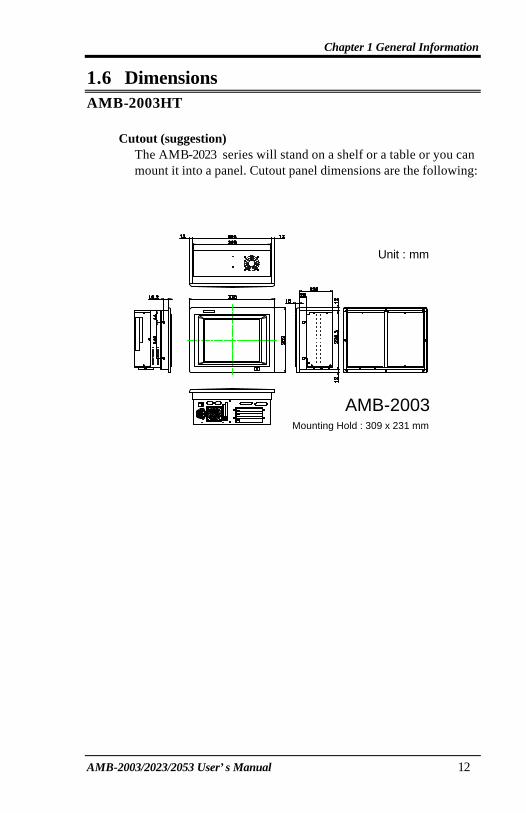
1.6 Dimensions AMB-2003HT
Cutout (suggestion)
The AMB-2023 series will stand on a shelf or a table or you can mount it into a panel. Cutout panel dimensions are the following:
AMB-2003Mounting Hold : 309 x 231 mm
Unit : mm
Chapter 1 General Information
AMB-2003/2023/2053 User’s Manual 13
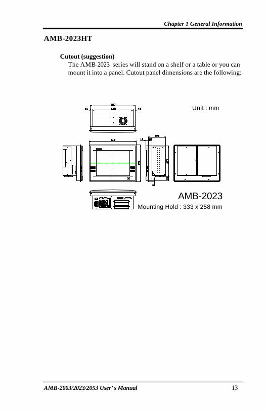
AMB-2023HT Cutout (suggestion)
The AMB-2023 series will stand on a shelf or a table or you can mount it into a panel. Cutout panel dimensions are the following:
AMB-2023Mounting Hold : 333 x 258 mm
Unit : mm
Chapter 1 General Information
AMB-2003/2023/2053 User’s Manual 14
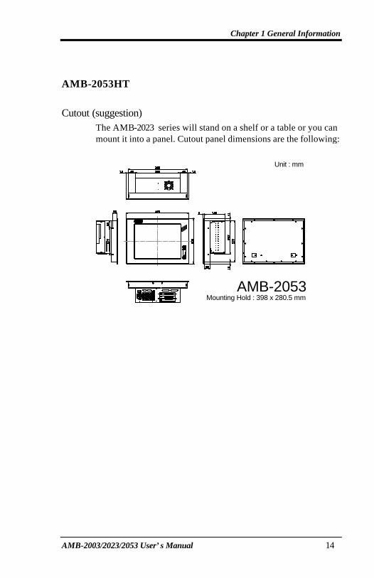
AMB-2053HT
Cutout (suggestion)
The AMB-2023 series will stand on a shelf or a table or you can mount it into a panel. Cutout panel dimensions are the following:
AMB-2053Mounting Hold : 398 x 280.5 mm
ON/OFF
DEC
INC
Unit : mm
Chapter 1 General Information
AMB-2003/2023/2053 User’s Manual 15
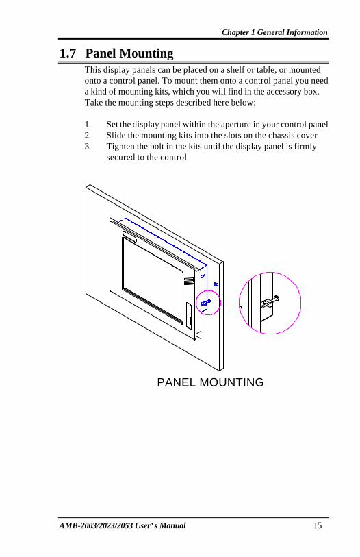
1.7 Panel Mounting This display panels can be placed on a shelf or table, or mounted onto a control panel. To mount them onto a control panel you need a kind of mounting kits, which you will find in the accessory box. Take the mounting steps described here below: 1. Set the display panel within the aperture in your control panel 2. Slide the mounting kits into the slots on the chassis cover 3. Tighten the bolt in the kits until the display panel is firmly
secured to the control
PANEL MOUNTING

Chapter 1 General Information
AMB-2003/2023/2053 User’s Manual 16
1.8 Packing List Then you should also check if the package contains the following items. You should contact your dealer immediately if any of these items are missing or damaged n One series industrial MMI panel PC with flat panel display n Disk for AMB-2003/2023/2053 series user’s manual n CI7BP (MBC-6310) user’s manual n Utility & Driver Disks: 3Pcs
- VGA Driver for Windows 95/ 98/ NT4.0 - Intel 82558B Driver Disk 1 - Intel 82558B Driver Disk 2
n Accessory - Plane for extension solution - Power cable for HDD & FDD - Screws bag - SCSI Cable (1M) - Power cord (1.8 M) - Assembly mounting parts
If any of their items are missing or damaged, contact your distributor or sales representative immediately.
Chapter 2 Introduction
AMB-2003/2023/2053 User’s Manual 14
2 Chapter2 MBC-6310 Introduction This manual is designed to give you information on the MBC-6310 CPU card. It is divided into the following sections:
Checklist....................................................................................... 15 Description .................................................................................. 16 Features........................................................................................ 17 Specifications.............................................................................. 18 Intelligence .................................................................................. 20 Board Dimensions ...................................................................... 21
The topics covered in this chapter are as follows:
u Checklist
u Description
u Features
u Specifications
u Layout of Key Components and Dimensions
Chapter 2 Introduction
AMB-2003/2023/2053 User’s Manual 15
Checklist
Please check that your package is complete and contains the items below. If you discover damaged or missing items, please contact your dealer.
• The MBC-6310 Industrial CPU Card
• This User’s Manual
• 1 Diskette containing Intel PCI IDE Driver and Flash Memory Utility
• 2 Diskettes containing C&T 69000 VGA Driver
• 2 Diskettes containing Intel 82558B LAN Driver
• 1 Diskette containing System Monitor utility
Chapter 2 Introduction
AMB-2003/2023/2053 User’s Manual 16
Description
The MBC-6310 is a Pentium II Industrial CPU card based on the Intel 440BX chipset and is fully designed for harsh industrial environment. It features a Socket-370 processor connector that is compatible with Intel Celeron processors. This card accommodates up to 256MB SDRAM configuration. The MBC-6310 comes with Winbond’s W83781D hardware monitoring device that monitors system and CPU temperature, system voltages, and CPU and chassis fan speeds to prevent system crashes by warning the user of adverse conditions. The power management feature provides power savings by slowing down the CPU clock, turning off the monitor screen and stopping the HDD spindle motor.
Chapter 2 Introduction
AMB-2003/2023/2053 User’s Manual 17
Features
• CPU Speed 300~850MHz, Intel Celeron, Coppermine processors
• Bus Speed 66MHz/100MHz
• Intel 440BX AGPset
• Up to 256 SDRAM system memory
• C&T 69000 VGA chipset for LCD & CRT displays
• Two RS-232 serial ports
• 16 level programmable watchdog timer, from 0-30 seconds
• High speed bi-directional SPP/ECP/EPP parallel port
• Hardware Monitoring, Win95 shut-off, Modem ring-on
• 10/100M Base-T Ethernet interface, Novell NE2000 Compatible

Chapter 2 Introduction
AMB-2003/2023/2053 User’s Manual 18
Specifications
• Processor Socket: Socket 370 connector
• Processor : Intel Celeron/Coppermine 300~850MHz
• Bus Speed: 66MHz and 100MHz
• Chipset: Intel 440BX AGPset with PCI EIDE and RTC built-in
• Secondary Cache: CPU integrated
• Memory Socket: One 168-pin DIMM socket Max. 256MB SDRAM Memory type: SDRAM (Synchronous DRAM)
• BIOS: Award BIOS, PnP support • FLASH EEPROM (256KB) for BIOS update • ISA Plug and Play (PnP) extension • Power management
• DMI BIOS Support: Desktop Management Interface (DMI) allows users to download system hardware-level information such as CPU type, CPU speed, internal/external frequencies and memory size.
• Multi I/O: Winbond W83977TF
• Parallel Port: One high-speed parallel port, SPP/EPP/ECP mode
• Serial Port: Two 16550 UART compatible ports configurable as RS232
• Enhanced IDE: Two Bus Mastering EIDE mode, up to 4 devices, Two EIDE interfaces for up to four devices, support PIO Mode 3/4 or Ultra DMA/33 IDE Hard Disk and ATAPI CD-ROM.
• FDD Interface: Two floppy drives (360KB, 720KB, 1.2MB, 1.44MB, 2.88MB, LS-120)
• CRT/LCD: C&T 69000 chipset • Embedded 2MB SDRAM display memory • Simultaneous CRT & LCD display • LCD panel supports DSTN/TFT • 1280x1024x8bpp colors CRT resolution • Up to 1280x1024x8bpp colors resolution for color active matrix
TFT panels (12, 18, and 24bit analog) or (12+12), (18+18) double pixel/CLK interface

Chapter 2 Introduction
AMB-2003/2023/2053 User’s Manual 19
• USB Interface: Two USB pin-header connectors, compliant with USB Specification Rev. 1.0
• DiskOnChip: The M-Systems flask disk supports system boot and storage capacity from 2MB to 72MB.
• Watchdog Timer: 16-level, programmable • I/O port 0443H to enable watchdog. • I/O port 0441H to disable watchdog. • Time-out timing select 0/2/4/6/8/10/12/14/16/18/20/22/
24/26/28/30 seconds (+/-20%).
• Green Function: Power management via BIOS, activated through mouse/keyboard movement
• PCI Bus Ethernet Interface: Intel 82558B chipset • PCI local bus Ethernet controller • Supports IEEE802.3u auto-negotiation for automatic speed
selection • support 10/100Mbps operation in a single port PCI bus master
architecture
• Keyboard and Mouse Connectors: PS/2 type mini-DIN that supports PC/AT; supports a 5-pin external keyboard connector
• IrDA Interface: Pin-header connector for the optional IrDA external connector
• Environmental and Mechanical: • Power Supply: 10A @+5V(max), ±12V:100mA(max) • Temperature: 0°C to 60°C • Humidity: 5% to 95% • Dimensions: 185mm x 129mm (7.3" x 5.0")

Chapter 2 Introduction
AMB-2003/2023/2053 User’s Manual 20
Intelligence
• Temperature Monitoring and Alert: A sensor for the CPU temperature on the MBC-6310 monitors the CPU temperature and alerts the user through the speaker or buzzer when temperature exceeds the safe heat level.
• Windows 95 shut-off: Allows shut-off control from within Windows 95 and through an ATX power supply.
• Modem ring-on: Allows system powering on through an external modem and through an ATX power supply.
• Year 2000 Compliant BIOS: The onboard Award BIOS is Year 2000 Compliant and will pass software applications that have the tendency to invoke INT1AH function 04H such as year2000.exe utility released by NSTL.
• Wake On LAN: Through an ATX power supply and network connection, systems can be turned on from the power-off state.
Chapter 2 Introduction
AMB-2003/2023/2053 User’s Manual 21
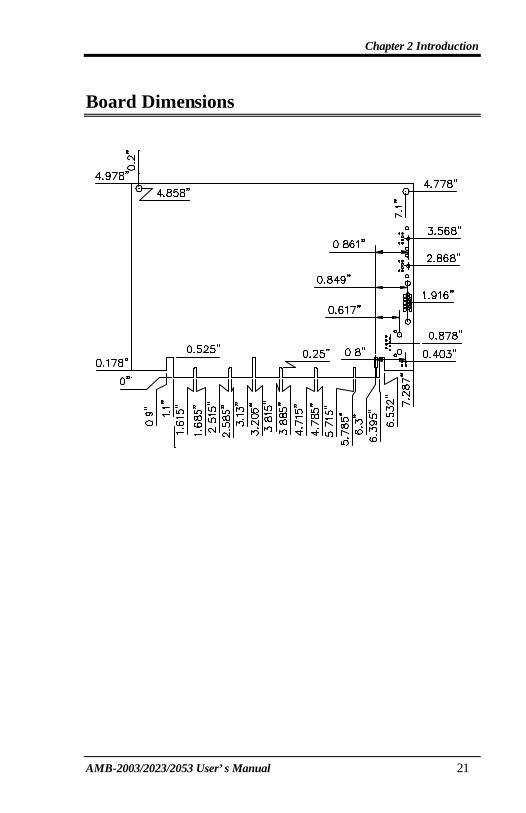
Board Dimensions
Chapter 3 Installations
AMB-2003/2023/2053 User’s Manual 22
3 Chapter3 MBC-6310 Installations This chapter provides information on how to use the jumpers and connectors on the MBC-6310 in order to set up a workable system. The topics covered are:
CPU Installation.......................................................................... 23 Memory Installation................................................................... 24 Jumpers on the MBC-6310 ........................................................ 25 Connectors on the MBC-6310 .................................................. 30 Watchdog Timer Configuration ............................................... 43
Chapter 3 Installations
AMB-2003/2023/2053 User’s Manual 23
CPU Installation The MBC-6310 Industrial CPU Card supports a Socket 370 connector processor socket for Intel Celeron processors. The Socket 370 connector uses a standard PGA socket connector. To install the CPU, insert it to the socket by aligning the notch of the Socket 370 CPU with the one of the PGA socket. After you have installed the processor into place, check if the jumper setting for the CPU speed is correct. NOTE: Ensure that the CPU heat sink and the CPU top surface are in
total contact to avoid CPU overheating problem that would cause your system to hang or be unstable.
Chapter 3 Installations
AMB-2003/2023/2053 User’s Manual 24
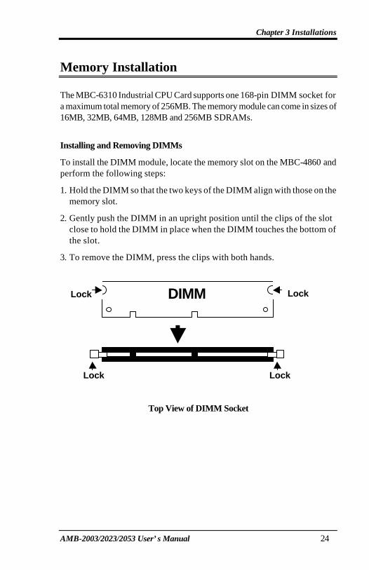
Memory Installation The MBC-6310 Industrial CPU Card supports one 168-pin DIMM socket for a maximum total memory of 256MB. The memory module can come in sizes of 16MB, 32MB, 64MB, 128MB and 256MB SDRAMs.
Installing and Removing DIMMs
To install the DIMM module, locate the memory slot on the MBC-4860 and perform the following steps:
1. Hold the DIMM so that the two keys of the DIMM align with those on the memory slot.
2. Gently push the DIMM in an upright position until the clips of the slot close to hold the DIMM in place when the DIMM touches the bottom of the slot.
3. To remove the DIMM, press the clips with both hands.
Top View of DIMM Socket
DIMM Lock Lock
Lock Lock

Chapter 3 Installations
AMB-2003/2023/2053 User’s Manual 25
Jumpers on the MBC-6310
The jumpers on the MBC-6310 allow you to configure your CPU card according to the needs of your applications. If you have doubts about the best jumper configuration for your needs, contact your dealer or sales representative. The following table lists the connectors on MBC-6310 and their respective functions.
Jumper Locations on the MBC-6310........................................ 26 DSW1 (1-8): CPU Frequency Selector..................................... 27 JP1: DiskOnChip BIOS Expansion Address Select................ 28 JP2: Clear CMOS Content.......................................................... 29 JP4: LCD Power Setting ............................................................. 29 S1: LCD Type Selector............................................................... 29
NOTE: Jumper J19 is for manufacturer testing use only. Remarks: The following conventions are used in this section:
off off on on
OPEN
SHORT

Chapter 3 Installations
AMB-2003/2023/2053 User’s Manual 26
Jumper Locations on the MBC-6310
NOTE: Jumper J19 is for manufacturer testing use only.
DISK ON CHIP
Chapter 3 Installations
AMB-2003/2023/2053 User’s Manual 27
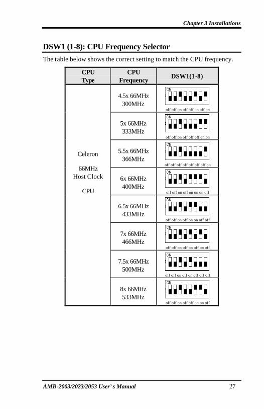
DSW1 (1-8): CPU Frequency Selector
The table below shows the correct setting to match the CPU frequency.
CPU Type
CPU Frequency
DSW1(1-8)
4.5x 66MHz 300MHz
off off on off off on off on
5x 66MHz 333MHz
off off on off off off on on
5.5x 66MHz 366MHz
off off off off off off off on
6x 66MHz 400MHz
off off on off on on on off
6.5x 66MHz 433MHz
off off on off on on off off
7x 66MHz 466MHz
off off on off on off on off
7.5x 66MHz 500MHz
off off on off on off off off
Celeron
66MHz Host Clock
CPU
8x 66MHz 533MHz
off off on off off on on off

Chapter 3 Installations
AMB-2003/2023/2053 User’s Manual 28
CPU Type
CPU Frequency
DSW1(1-8)
4.5x 100MHz 450MHz
off off on off off on off on
5x 100MHz 500MHz
off off on off off off on on
5.5x 100MHz 550MHz
off off off off off off off on
6x 100MHz 600MHz
off off on off on on on off
6.5x 100MHz 650MHz
off off on off on on off off
7x 100MHz 700MHz
off off on off on off on off
7.5x 100MHz 750MHz
off off on off on off off off
Coppermine
100MHz Host Clock
CPU
8x 100MHz 800MHz
off off on off off on on off
JP1: DiskOnChip BIOS Expansion Address Select
JP1 Address
1 3 D0000-D7FFF
1 3 D8000-DFFFF (default)

Chapter 3 Installations
AMB-2003/2023/2053 User’s Manual 29
JP2: Clear CMOS Content
JP2 Setting Function
1 3
Pin 2-3 Short/Closed Clear CMOS Content
1 3 Pin 1-2
Short/Closed Normal Operation
JP4: LCD Power Setting
The MBC-6310 XGA interface supports 5V and 3.3V LCD displays. Use JP4 to change between 5V (default) and 3.3V panel video signal level.
JP4 Setting
1 3 5V (default)
1 3 3.3V
Chapter 3 Installations
AMB-2003/2023/2053 User’s Manual 30
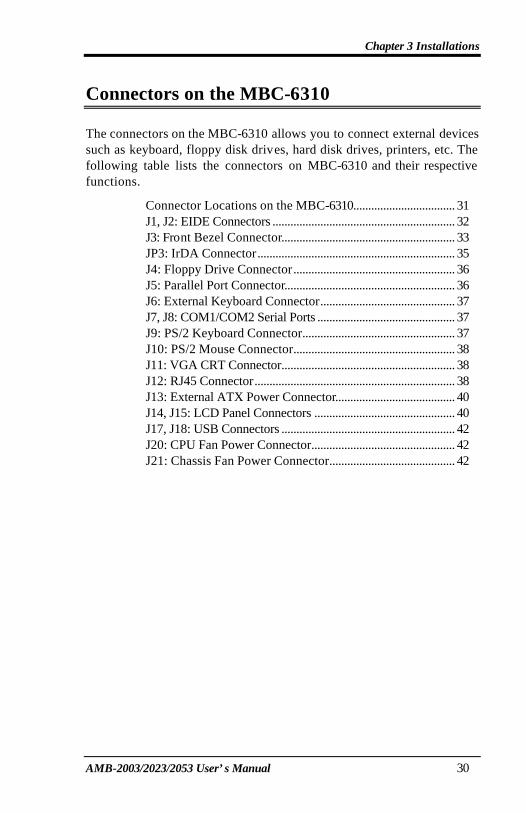
Connectors on the MBC-6310 The connectors on the MBC-6310 allows you to connect external devices such as keyboard, floppy disk drives, hard disk drives, printers, etc. The following table lists the connectors on MBC-6310 and their respective functions.
Connector Locations on the MBC-6310.................................. 31 J1, J2: EIDE Connectors ............................................................. 32 J3: Front Bezel Connector.......................................................... 33 JP3: IrDA Connector.................................................................. 35 J4: Floppy Drive Connector...................................................... 36 J5: Parallel Port Connector......................................................... 36 J6: External Keyboard Connector............................................. 37 J7, J8: COM1/COM2 Serial Ports .............................................. 37 J9: PS/2 Keyboard Connector................................................... 37 J10: PS/2 Mouse Connector...................................................... 38 J11: VGA CRT Connector.......................................................... 38 J12: RJ45 Connector................................................................... 38 J13: External ATX Power Connector........................................ 40 J14, J15: LCD Panel Connectors ............................................... 40 J17, J18: USB Connectors .......................................................... 42 J20: CPU Fan Power Connector................................................ 42 J21: Chassis Fan Power Connector.......................................... 42

Chapter 3 Installations
AMB-2003/2023/2053 User’s Manual 31
Connector Locations on the MBC-6310
DISK ON CHIP

Chapter 3 Installations
AMB-2003/2023/2053 User’s Manual 32
J1, J2: EIDE Connectors
J1: Primary IDE Connector
Signal Name Pin # Pin # Signal Name Reset IDE 1 2 Ground
Host data 7 3 4 Host data 8 Host data 6 5 6 Host data 9 Host data 5 7 8 Host data 10 Host data 4 9 10 Host data 11 Host data 3 11 12 Host data 12 Host data 2 13 14 Host data 13 Host data 1 15 16 Host data 14 Host data 0 17 18 Host data 15
Ground 19 20 Key DRQ0 21 22 Ground
Host IOW 23 24 Ground Host IOR 25 26 Ground IOCHRDY 27 28 Host ALE
DACK0 29 30 Ground IRQ14 31 32 No connect
Address 1 33 34 No connect Address 0 35 36 Address 2
Chip select 0 37 38 Chip select 1
J1
Activity 39 40 Ground

Chapter 3 Installations
AMB-2003/2023/2053 User’s Manual 33
J2: Secondary IDE Connector
Signal Name Pin # Pin # Signal Name Reset IDE 1 2 Ground
Host data 7 3 4 Host data 8 Host data 6 5 6 Host data 9 Host data 5 7 8 Host data 10 Host data 4 9 10 Host data 11 Host data 3 11 12 Host data 12 Host data 2 13 14 Host data 13 Host data 1 15 16 Host data 14 Host data 0 17 18 Host data 15
Ground 19 20 Key DRQ1 21 22 Ground
Host IOW 23 24 Ground Host IOR 25 26 Ground IOCHRDY 27 28 Host ALE
DACK1 29 30 Ground IRQ15 31 32 No connect
Address 1 33 34 No connect Address 0 35 36 Address 2
Chip select 0 37 38 Chip select 1
J2
Activity 39 40 Ground
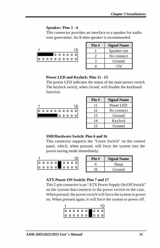
J3: Front Bezel Connector
The front bezel o f the case has a control panel that provides light indication of the computer activities and switches to change the computer status. J1 is a 20-pin header that provides interfaces for the following functions.
Hard Disk Drive LED
Reset Switch Turbo LED Connector
ATX Power On Switch SMI / Hardware Switch
Power LED and Keylock
Speaker
Chapter 3 Installations
AMB-2003/2023/2053 User’s Manual 34
Speaker: Pins 1 - 4
This connector provides an interface to a speaker for audio tone generation. An 8-ohm speaker is recommended.
Pin # Signal Name
1 Speaker out 2 No connect 3 Ground
4 +5V
Power LED and Keylock: Pins 11 - 15
The power LED indicates the status of the main power switch. The keylock switch, when closed, will disable the keyboard function.
Pin # Signal Name
11 Power LED 12 No connect 13 Ground 14 Keylock
15 Ground SMI/Hardware Switch: Pins 6 and 16
This connector supports the "Green Switch" on the control panel, which, when pressed, will force the system into the power-saving mode immediately.
Pin # Signal Name
6 Sleep 16 Ground
ATX Power ON Switch: Pins 7 and 17 This 2-pin connector is an “ATX Power Supply On/Off Switch” on the system that connects to the power switch on the case. When pressed, the power switch will force the system to power on. When pressed again, it will force the system to power off.
Chapter 3 Installations
AMB-2003/2023/2053 User’s Manual 35
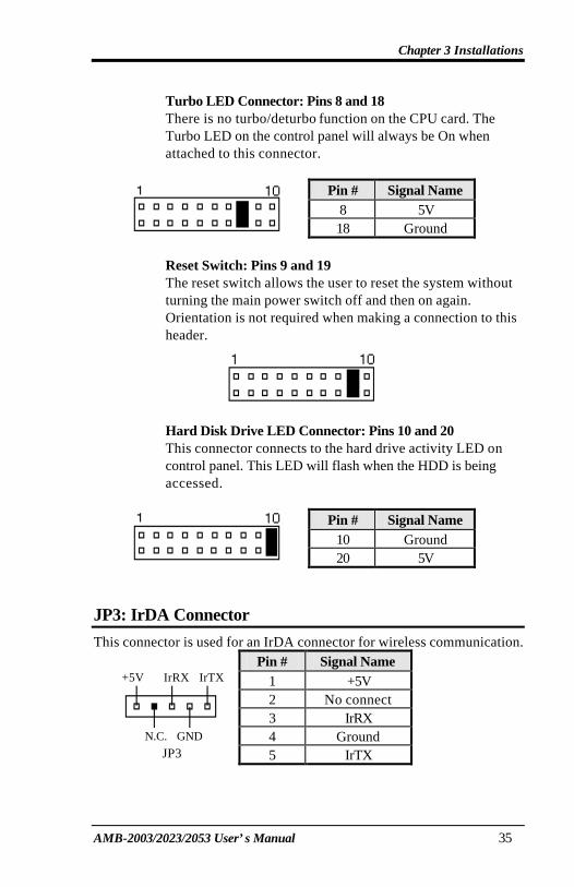
Turbo LED Connector: Pins 8 and 18
There is no turbo/deturbo function on the CPU card. The Turbo LED on the control panel will always be On when attached to this connector.
Pin # Signal Name
8 5V
18 Ground Reset Switch: Pins 9 and 19
The reset switch allows the user to reset the system without turning the main power switch off and then on again. Orientation is not required when making a connection to this header.
Hard Disk Drive LED Connector: Pins 10 and 20
This connector connects to the hard drive activity LED on control panel. This LED will flash when the HDD is being accessed.
Pin # Signal Name
10 Ground 20 5V
JP3: IrDA Connector
This connector is used for an IrDA connector for wireless communication. Pin # Signal Name
1 +5V 2 No connect 3 IrRX 4 Ground
+5V IrRX IrTX
N.C. GND
JP3 5 IrTX

Chapter 3 Installations
AMB-2003/2023/2053 User’s Manual 36
J4: Floppy Drive Connector
J4 is a 34-pin header and will support up to 2.88MB floppy drives.
Signal Name Pin # Pin # Signal Name
Ground 1 2 RM/LC Ground 3 4 No connect Ground 5 6 No connect Ground 7 8 Index Ground 9 10 Motor enable 0 Ground 11 12 Drive select 1 Ground 13 14 Drive select 0 Ground 15 16 Motor enable 1 Ground 17 18 Direction Ground 19 20 Step Ground 21 22 Write data Ground 23 24 Write gate Ground 25 26 Track 00 Ground 27 28 Write protect Ground 29 30 Read data Ground 31 32 Side 1 select
J4
Ground 33 34 Diskette change
J5: Parallel Port Connector
The following table describes the pin out assignments of this connector.
Signal Name Pin # Pin # Signal Name
Line printer strobe 1 14 AutoFeed PD0, parallel data 0 2 15 Error PD1, parallel data 1 3 16 Initialize PD2, parallel data 2 4 17 Select PD3, parallel data 3 5 18 Ground PD4, parallel data 4 6 19 Ground PD5, parallel data 5 7 20 Ground PD6, parallel data 6 8 21 Ground PD7, parallel data 7 9 22 Ground ACK, acknowledge 10 23 Ground
Busy 11 24 Ground
J5 Paper empty 12 25 Ground

Chapter 3 Installations
AMB-2003/2023/2053 User’s Manual 37
Select 13 N/A N/A
J6: External Keyboard Connector
1 Pin # Signal Name
1 Keyboard clock 2 Keyboard data 3 NC
4 GND 5 5 Vcc J6
J7, J8: COM1/COM2 Serial Ports
J7 and J8, 10-pin header connectors, are the onboard serial ports of MBC-6310. The following table shows the pin assignments of this connector.
Pin # Signal Name
1 DCD, Data carrier detect 2 RXD, Receive data 3 TXD, Transmit data 4 DTR, Data terminal ready 5 GND, ground 6 DSR, Data set ready 7 RTS, Request to send 8 CTS, Clear to send
.
J7, J8
9 RI, Ring indicator 10 NC
J9: PS/2 Keyboard Connector
Pin # Signal Name
1 Keyboard data 2 N.C.
3 GND

Chapter 3 Installations
AMB-2003/2023/2053 User’s Manual 38
4 5V 5 Keyboard clock
J9
6 N.C.
J10: PS/2 Mouse Connector
Pin # Signal Name
1 Mouse data 2 N.C. 3 N.C. 4 5V 5 Mouse Clock
J10
6 N.C.
J11: VGA CRT Connector
The pin assignments of the J11 VGA CRT connector are as follows:
Signal Name Pin Pin Signal Name
Red 1 2 Green Blue 3 4 N.C. GND 5 6 GND GND 7 8 GND N.C. 9 10 GND N.C. 11 12 N.C.
HSYNC 13 14 VSYNC
J11
NC 15
J12: RJ45 Connector
This connector is for the 10/100Mbps Ethernet capability of the CPU card. The figure below shows the pin out assignments of this connector and its corresponding input jack.

Chapter 3 Installations
AMB-2003/2023/2053 User’s Manual 39
J12
TD+(pin#1) TD-(pin#2) RD+(pin#3)
RD-(pin#6)

Chapter 3 Installations
AMB-2003/2023/2053 User’s Manual 40
J13: External ATX Power Connector
Pin # Signal Name
1 GND 2 PS-ON (soft on/off) 3 5V SB (standby +5V)
1 3 J13
J14, J15: LCD Panel Connectors
J14 and J15 are pin headers for flat panel LCD displays. The following shows the pin assignments of this connector.
Signal Name Pin # Pin # Signal Name
+12V 1 2 +12V GND 3 4 GND 5V/3.3V 5 6 5V/3.3V ENAVEE 7 8 GND
P0 9 10 P1 P2 11 12 P3 P4 13 14 P5 P6 15 16 P7 P8 17 18 P9 P10 19 20 P11 P12 21 22 P13 P14 23 24 P15 P16 25 26 P17 P18 27 28 P19
P20 29 30 P21 P22 31 32 P23 GND 33 34 GND
SHFCLK 35 36 FLM MDE 37 38 LP
J15 GND 39 40 ENABKL
GND 41 42 LCDVDD DNAVDD 43 44 5V/3.3V

Chapter 3 Installations
AMB-2003/2023/2053 User’s Manual 41
Signal Name Pin # Pin # Signal Name
P24 1 2 P25 P26 3 4 P27 P28 5 6 P29 P30 7 8 P31
P32 9 10 P33
J14 P34 11 12 P35
Flat Panel Display Interface Pin Descriptions
Mono Mono Mono Color Color Color Color Color Color Color Color Color
SS DD DD TFT TFT TFT TFT TFT+HR STN-SS STN-SS STN-DD STN-DD
Pin Name 8-bit 8-bit 16-bit 9/12/16 bit 18/24 bit
36-bit 18/24 bit
8-bit (4bP)
16-bit (4bP)
8-bit (4bP)
16-bit (4bP)
24-bit
P0 D0 UD3 UD7 B0 B0 FB0 FB0 R1 R1 UR1 UR0 UR0
P1 D1 UD2 UD6 B1 B1 FB1 FB1 B1 G1 UG1 UG0 UG0
P2 D2 UD1 UD5 B2 B2 FB2 FB2 G2 B1 UB1 UB0 UB0
P3 D3 UD0 UD4 B3 B3 FB3 FB3 B3 R2 UB2 UR1 LR0
P4 D4 LD3 UD3 B4 B4 FB4 SB0 G4 G3 LR1 LR0 LG0
P5 D5 LD2 UD2 G0 B5 FB5 SB1 R5 B2 LG1 LG0 LB0
P6 D6 LD1 UD1 G1 B6 SB0 SB2 B5 R3 LB1 LB0 UR1
P7 D7 LD0 UD0 G2 B7 SB1 B3 G3 LR2 LR1 UG1
P8 LD7 G3 G0 SB2 FG0 B3 UG1 UB1
P9 LD6 G4 G1 SB3 FG1 R4 UB1 LR1
P10 LD5 G5 G2 SB4 FG2 G4 UR2 LG1
P11 LD4 R0 G3 SB5 FG3 B4 UG2 LB1
P12 LD3 R1 G4 FG0 SG0 R5 LG1 UR2
P13 LD2 R2 G5 FG1 SG1 G5 LB1 UG2
P14 LD1 R3 G6 FG2 SG2 B5 LR2 UB2
P15 LD0 R4 G7 FG3 SG3 G6 LG2 LR2
P16 R0 FG4 FR0 LG2
P17 R1 FG5 FR1 LB2
P18 R2 SG0 FR2 UR3
P19 R3 SG1 FR3 UG3
P20 R4 SG2 SR0 LR3
P21 R5 SG3 SR1 LG3
P22 R6 SG4 SR2 LB3
P23 R7 SG5 SR3
P24 FR0
P25 FR1
P26 FR2
P27 FR3
P28 FR4
P29 FR5
P30 SR0
P31 SR1
P32 SR2
P33 SR3
P34 SR4
P35 SR5
SHFCLK SHFCLK SHFCLK SHFCLK SHFCLK SHFCLK SHFCLK SHFCLK SHFCLK SHFCLK SHFCLK SHFCLK SHFCLK
Pixels/Clk: 8 8 16 1 1 2 2 2-2/3 5-1/3 2-2/3 5-1/3 8 P24

Chapter 3 Installations
AMB-2003/2023/2053 User’s Manual 42
J17, J18: USB Connectors
The following table shows the pin outs of the USB connectors.
J18 Pin # J17 Pin # Signal Name
1 1 Vcc 2 2 USB- 3 3 USB+
J18
1
2
3
4
J17
1
2
3
4 4 4 Ground
J20: CPU Fan Power Connector
J20 is a 3-pin header for the CPU fan power. The fan must be a 12V fan.
Pin # Signal Name
1 Rotation 2 +12V
1 2 3
3 Ground
J21: Chassis Fan Power Connector
J21 is a 3-pin header for the chassis fan power. The fan must be a 12V fan.
Pin # Signal Name
1 Rotation 2 +12V
1 2 3
3 Ground
Chapter 3 Installations
AMB-2003/2023/2053 User’s Manual 43
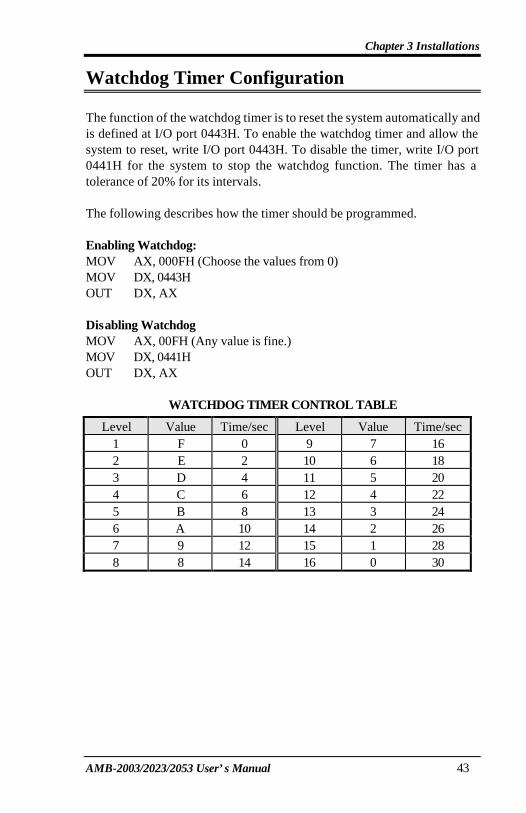
Watchdog Timer Configuration The function of the watchdog timer is to reset the system automatically and is defined at I/O port 0443H. To enable the watchdog timer and allow the system to reset, write I/O port 0443H. To disable the timer, write I/O port 0441H for the system to stop the watchdog function. The timer has a tolerance of 20% for its intervals. The following describes how the timer should be programmed. Enabling Watchdog: MOV AX, 000FH (Choose the values from 0) MOV DX, 0443H OUT DX, AX Disabling Watchdog MOV AX, 00FH (Any value is fine.) MOV DX, 0441H OUT DX, AX
WATCHDOG TIMER CONTROL TABLE
Level Value Time/sec Level Value Time/sec 1 F 0 9 7 16 2 E 2 10 6 18 3 D 4 11 5 20 4 C 6 12 4 22 5 B 8 13 3 24 6 A 10 14 2 26 7 9 12 15 1 28 8 8 14 16 0 30

Chapter 3 Installations
AMB-2003/2023/2053 User’s Manual 44
Exploded Diagram The Award BIOS (Basic Input/Output System) installed in your system’s ROM supports NS Geode processors in a standard IBM-AT compatible I/O system. The BIOS provides critical low-level support for standard devices such as disk drives, parallel port and serial ports. It also adds virus and password protection, as well as special support for detailed fine-tuning of the chipset controlling the entire system.

Chapter 3 Installations
AMB-2003/2023/2053 User’s Manual 45
Cooling Fan Replacement To Service or replace the cooling fan need to remove the rear protective cover and use this diagram as a guide when assembling and disassembling your cooling fan
Chapter 3 Installations
AMB-2003/2023/2053 User’s Manual 46
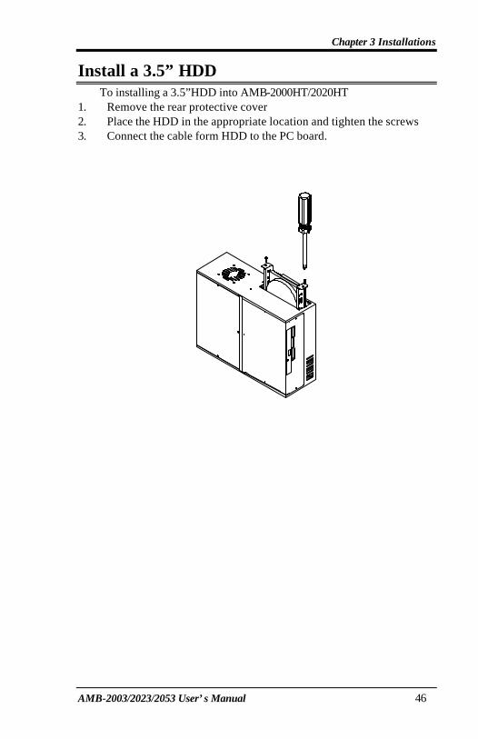
Install a 3.5” HDD To installing a 3.5”HDD into AMB-2000HT/2020HT 1. Remove the rear protective cover 2. Place the HDD in the appropriate location and tighten the screws 3. Connect the cable form HDD to the PC board.

Chapter 3 Installations
AMB-2003/2023/2053 User’s Manual 47
Install a Slim CD-Rom, FDD and 2.5” HDD To installing a slim FDD & CD-ROM into AMB-2023HT/2053HT
1. Remove the rear protective cover 2. Place the FDD & CD-ROM in the appropriate location and
tighten the screws 3. Connect the cable form HDD to the PC board.