-- computer organization and architecturesimonfoucher.com/mcgill/ecse425 comp arc...
TRANSCRIPT
/ Student ID: Signature:
Course 304-425B -- Computer Organization and Architecture
Final examination
April 18,2000,9:00 -- 12:00
Examiner: Prof. V. Hayward
Associate Examiner: Prof. K. Khordoc
INSTRUCTIONS
This is a closed book examination. Calculators and up to two sheets of notes are allowed.
Explain every result concisely when asked. Marks will be given for clear, concise solutions.
State any assumption required for an answer if it is not clear in the text of the question.
This exam has 12 pages including this one. It has 7 sections for 24 questions (including a bonus question) indicated by the bullet sign (a). The marks add up to 100.
Please sign this paper at the top of the page, write your name and student number legibly there.
Put your answers in the space provided and keep all the pages together.
PLEASE NOTE CAREFULLY
Make sure that the signed paper in its entirety is handed in (along with all signed exam books) at the end of examination.
Make sure that the answers are put in the space provided, answers in any other location will not be marked.
You have approximately 180 minutes to complete the exam.
/ Section I: Performance (12 points)
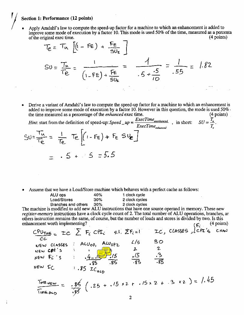
/ Apply Arndahl's law to compute the speed-up factor for a machine to which an enhancement is added to improve some mode of execution by a factor 10. This mode is used 50% of the time, measured as a percenta of the original exec time. - (4 points)
Derive a variant of Arndahl's law to compute the speed-up factor for a machine to which an enhancement is added to improve some mode of execution by a factor 10. However in this question, the mode is used 50% 1
the time measured as a percentage of the enhanced exec time. (4 points)
Hint: start from the definition of speed-up: Speed -up = ExecTimeunenhnced , in su = 7;. ExecTimeenhnced <
Assume that we have a Loadstore machine which behaves with a perfect cache as follows: ALU ops 40% 1 clock cycle LoadIStores 30% 2 clock cycles Branches and others 30% 2 clock cycles
The machine is modified to add new ALU instructions that have one source operand in memory. These new register-memory instructions have a clock cycle count of 2. The total number of ALU operations, branches, ar others instruction remains the same, of course, but the number of loads and stores is divided by two. Is this enhancement worth implementing? (4 points)
5.1. ZF<;.=I ZC, CLfiSSE5 ,
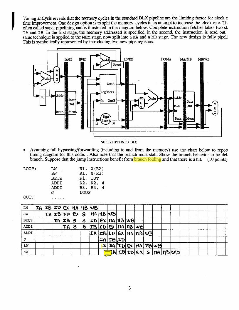
Timing analysis reveals that the memory cycles in the standard DLX pipeline are the limiting factor for clock c time improvement. One design option is to split the memory cycles in an attempt to increase the clock rate. Th often called super pipelining and is illustrated in the diagram below. Complete instruction fetches takes two st; IA and IB. In the first stage, the memory addressed is specified, in the second, the instruction is read out. same technique is applied to the MEM stage, now split into a MA and a MB stage. The new design is fully pipeli This is symbolically represented by introducing two new pipe registers.
SUPERPIPELINED DLX
Assuming full bypassinglforwarding (including to and from the memory) use the chart below to repon timing diagram for this code. . Also note that the branch must stall. Show the branch behavior to be del, branch. Suppose that the jump instructions benefit from branch folding and that there is a hit. (10 points)
LOOP : LW R 1 , O ( R 2 ) S W R 1 , O ( R 3 ) BEQZ R 1 , OUT ADD1 R 2 , R 2 , 4 ADD1 R 3 , R 3 , 4 J LOOP
OUT : . . . . .
LW
sw BEQZ
ADD1
ADD1 7
J
L w SW
I A 28 ZA
ZDE$ ZB ~6
ttA E$ s 8
ZP rs ZA
s 5 s
tlBWB HA ZD r a r ~ I3
ns EX
x 0 Z D rf4 I%
VJB n4 EF
zB
s
~ I A f x ,ZO
%'ED t%\NB
r(Bwf3 n~ HA
U( Z A T B ~ D E X vknbw(3
WB
fl8

STANDARD DLX PIPELINE
Recall that there are four basic techniques to handle branches in a pipeline like DLX's: (A) flush (or freeze) a number of instructions after the branch; (B) static prediction such as "predict-not-taken (C) delayed branch which creates "delay slots"; (D) delayed branch with canceling.
Consider now the following sequence to compute the double of the absolute value of a number in memory:
1. LW R 2 , O ( R 3 ) \ \ load number 2 . S L T I R 1 , R 2 , 0 \ \ R 1 <-- 1 i f a < 0 3. BEQZ R 1 , S K I P \ \ skip i f a > 0 4 . SUB R 2 , RO, R2 \ \ negate 5 . SKIP: ADD R 2 , R 2 , R2 \ \ double 6 . SW O ( R 3 ) , r 2 \ \ store back
Show the timing of this sequence for the DLX pipeline assuming full forwarding and bypassing hardware assuming a register read and a write in the same clock cycle implicitly "forwards" through the register file 6 first and then read). Use the chart to show the timing of instructions starting at instruction SLTI when the bn is taken. Fill-in the two blank entries according to the case. (note: a similar question was given last term, howel is NOT the same question).
(B)"predict-not-taken": . . . (5 points)
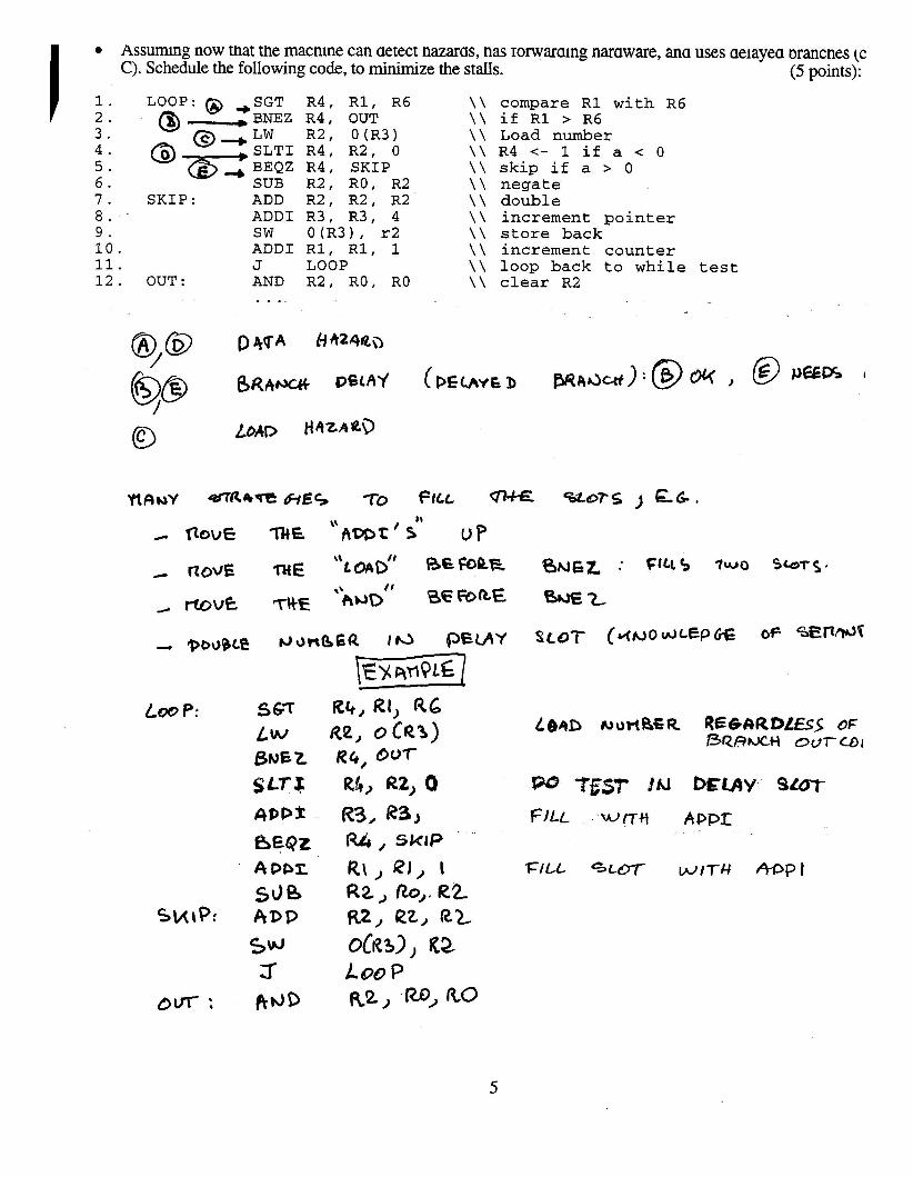
~ssurmng now tnat tne macme can aetect nazaras, nas rorwarang naraware, ana uses aelayea Prancnes (c C). Schedule the following code, to minimize the stalls. (5 points):
LOOP: @ ,SGT R 4 , R 1 , R 6 \ \ @ . . . . BNEZ R 4 , OUT \ \
@,LW R 2 , O ( R 3 ) \ \ SLTI R 4 , R 2 , 0 \ \ BEQZ R 4 , SKIP \ \ SUB R 2 , RO, R2 \ \
SKIP: ADD R 2 , R 2 , R2 \ \ ADD1 R 3 , R 3 , 4 \ \ SW 0 ( R 3 ) , r2 \ \ ADD1 R 1 , R 1 , 1 \ \ J LOOP \ \
OUT : AND R 2 , RO, RO \ \
compare R 1 with R 6 if R 1 > R 6 Load number R 4 <- 1 if a < 0 skip if a > 0 negate double increment pointer store back increment counter loop back to while test clear R2
4.00 p: 567 Rb, RI, a6 Lw RP, 0c43) ~ o r t & S R Q E ~ C I R D L E S ~ OF
BRRMH ourcol BNEZ RG, 007
R3, R ~ J FILL W K H AQPI M , SctrP
R \ , QI, I FILL +LOT- WITH MPI R2. no,. R 2 uz, rZz, R Z
oCR~J, R 2 l oo P R2, 4 RO
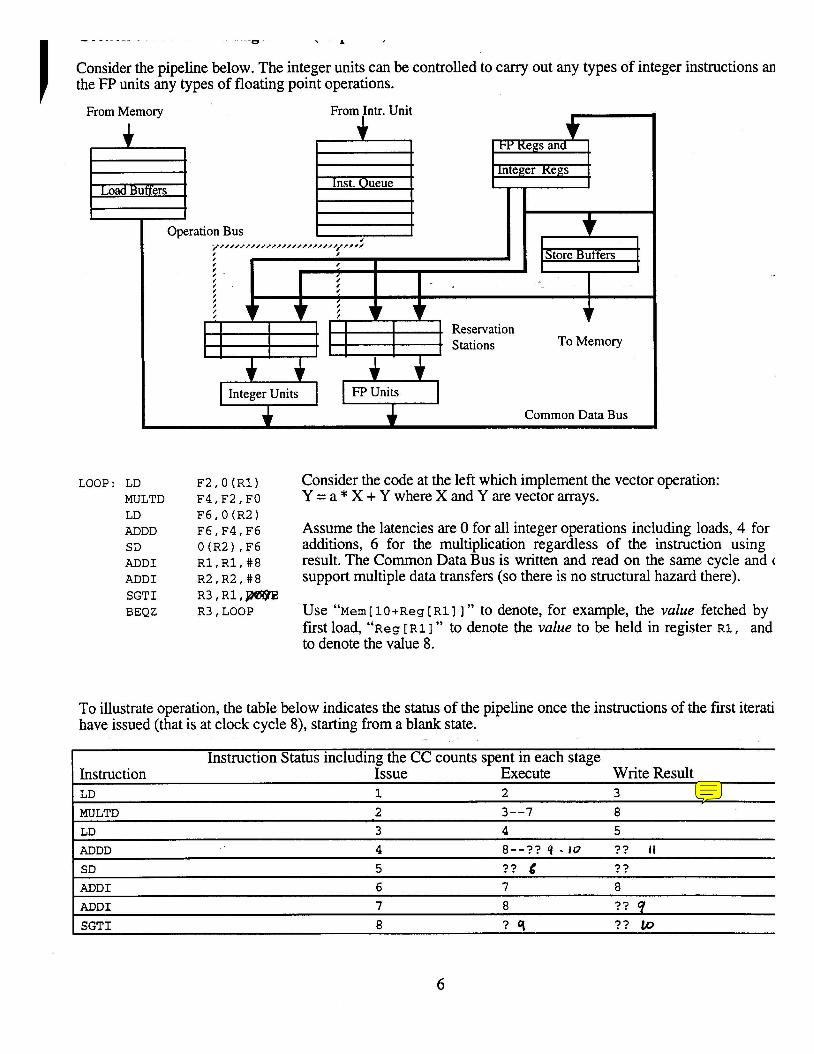
Consider the pipeline below. The integer units can be controlled to carry out any types of integer instructions an the FP units any types of floating point operations.
From Memory
Common Data Bus
LOOP: LD MULTD LD ADDD SD ADDI ADDI SGTI BEQZ
F2,O(R1) F4,F2,FO F6,O (R2) F6,F4,F6 O(R2) ,F6 Rl,R1,#8 R2,R2,#8 R3,Rl,W@E R3, LOOP
Consider the code at the left which implement the vector operation: Y = a * X + Y where X and Y are vector arrays.
Assume the latencies are 0 for all integer operations includmg loads, 4 for additions, 6 for the multiplication regardless of the instruction using result. The Common Data Bus is written and read on the same cycle and ( support multiple data transfers (so there is no structural hazard there).
Use em [ 10 +Reg [ ~1 I I " to denote, for example, the value fetched by first load, " ~ e ~ [RI 1 " to denote the value to be held in register RI, and to denote the value 8.
To illustrate operation, the table below indicates the status of the pipeline once the instructions of the first iterati have issued (that is at clock cycle 8), starting from a blank state.
Instruction Status including the CC counts spent in each stage Instruction Issue Execute Write Result LD 1 2 3
MULTD 2 3--7 8
LD 3 4 5
ADDD 4 8--?? 4 - 10 ? ? I t SD 5 ? ? 6 ? ?
ADD1 6 7 8
ADD1 7 8 ? ? 9 SGTI 8 ? q ? ? Lo
V ' V ' ' " - - C
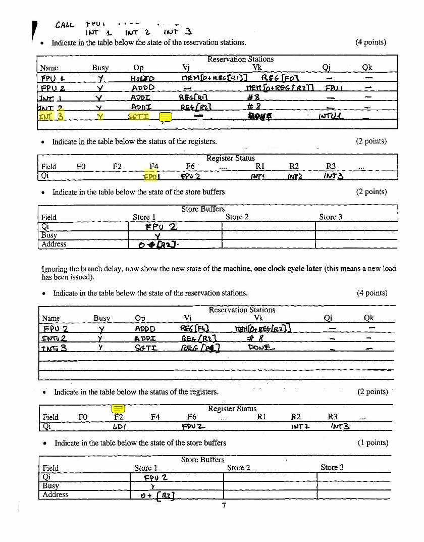
Im & INT , Z IUT 3 Indicate in the table below the state of the reservation stations. (4 points)
Reservation Stations vj Vk Name Busy Op Qk
Ffc) b Y Hum0 nmJlro+ ~ e c t q r ~ l R€G [ F O ~ .L - FPU 2 V ADDD - rtr6+~€~t~2n ZPUI .L
h g \ V ADDZ R S G ~ R ~ ~ dl3 - - 3- Y A@nZ tt 8 - -
.fhC 3 Y S G T T ry l h J " w ~ ,
Indicate in the table below the status of the registers. (2 points)
Register Status Field FO F2 F4 F6 .... R1 R2 R3 . . . Qi em I 2 iwa m a rm-3
Indicate in the table below the state of the store buffers (2 points)
I Store Buffers 1
Ignoring the branch delay, now show the new state of the machine, one clock cycle later (this means a new load has been issued).
Field Store 1 Store 2 Store 3 Qi Fpu 2. I
Indicate in the table below the state of the reservation stations. (4 points)
Busy Address
Indicate in the table below the status of the registers. (2 points)
V t?-e&a-
Register Status Field FO F2 F4 F6 ... R1 R2 R3 ... Qi LD I ~ 0 9 Z 4 - t 0 ~ ~ 3
Indicate in the table below the state of the store buffers (1 points)
Store Buffers Field Store 1 Store 2 Store 3 Qi Busy
FPU '2 L
, Address O + fa21 7
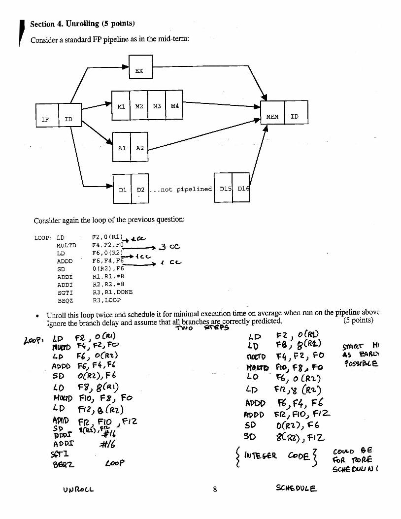
I Section 4. Unrolling (5 points)
Consider a standard FP pipeline as in the mid-term:
Consider again the loop of the previous question:
LOOP: LD F2,O (R1)+b& MULTD F4,F2,FO - 3 cc LD F6,0(R2),ce/ ADDD F6,F4,F6 4 c t SD 0 (R2) , F6 ADD1 Rl,R1,#8 ADD1 R2,R2,#8 SGTI R3, R1, DONE BEQZ R3, LOOP
Unroll this loop twice and schedule it for minimal execution time on average when run on the pipeline above Ignore the branch delay and assume that all branches are correctly predicted. (5 points)
T w o %rep5
&?09* LP , o CR,) ,f, F t ) o ~ M I fim fb, F2,fo LD F6,8(R*) cp+nr HI I D F d , o C ~ r ) ? 4 , ~ 2 , F o 4 5 mRo ADDO F6, F 4 1 61 WuO FloJ F8, M B0SPcE so 0[u2), F6 Lo %, o IRI~ Lo F3) !,&I) LP F ~ > Y [ R ~ Hm FIO, F8, Fo LD H~,BCRZ) RPPD FR, FIO, FIZ
SD o(R~>, c6
ADOX =#I6 SQ ~ ~ R ~ ) , F I z covco 8E
Loo? 0@2 5c#€Duun)(
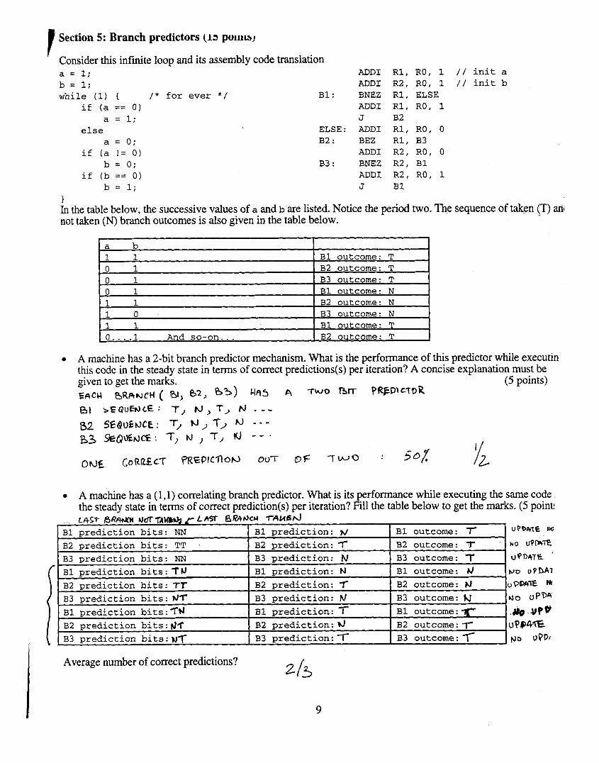
( Section 5: Branch predictors (13 pulrrw, r
Consider this infinite loop and its assembly code translation a = 1; b = 1; while (1) { / * for ever * / B1:
if (a == 0) a = 1;
else ELSE : a = 0; B2 :
if (a != 0) b = 0; B3 :
if (b == 0) b = 1;
ADDI ADDI BNEZ ADDI J ADDI BEZ ADDI BNEZ ADDI J
R1, RO, 1 / / init a R2, RO, 1 / / init b R1, ELSE R1, RO, 1 B 2 R1, RO, 0 R1, B3 R2, RO, 0 R2, B1 R2, RO, 1 B1
1 In the table below, the successive values of a and b are listed. Notice the period two. The sequence of taken (T) ant not taken (N) branch outcomes is also given in the table below.
A machine has a Zbit branch predictor mechanism. What is the performance of this predictor while executin this code in the steady state in terms of correct predictions(s) per iteration? A concise explanation must be given to get the marks. (5 points) EnCu f3R~wct-l ( %I, 62, 03) H65 7wo nrr PWP\CTQR
- a b 1 1 0 1 0 1 0 1
- 1 1 1 0 1 1 0.. . .1 And so-on . . .
B1 outcome: T B2 outcome: T B3 outcome: T B1 outcome: N B2 outcome: N B3 outcome: N B1 outcome: T B2 outcome: T
A machine has a (1,l) correlating branch predictor. What is its performance while executing the same code the steady state in terms of correct prediction(s) per iteration? Fill the table below to get the marks. (5 point!
- LAST A R M U O T ~ A W * ] ~ LAW 6Q~)AFlccl TAW^^
Average number of correct predictions? 2 /3
uPD&T€ w
NO uQm'iE
uQn4TE '
PJD uPDAl UP%= bJ4
r ~ o V P D ~ ~ l o . - U ? * ~'394* pa 0 W f
B1 outcome: 7- B2 outcome: 7 B3 outcome: T
B1 prediction bits: NN B2 prediction bits: TT B3 prediction bits: NN
i B1 prediction: hl
B2 prediction: T B3 prediction: N B1 prediction: N
B2 prediction: 7 B3 prediction: fd B1 prediction: B2 prediction: ?J
B3 prediction:
B1 prediction bits:T).t
B2 prediction bits: T I
B3 prediction bits: h17 B1 prediction bits : TbJ
B2 prediction bits : JT B3 prediction b i t s : ~ T
B1 outcome: &/
B2 outcome: )3
B3 outcome: hj
B1 outcome:r B2 outcome: 7' B3 outcome: 7
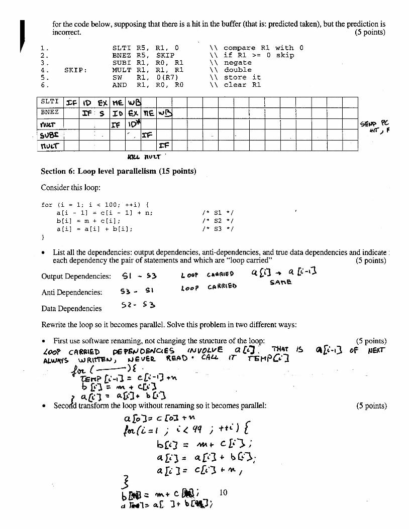
for the code below, supposing that there is a hit in the buffer (that is: predicted taken), but the prediction is incorrect. (5 points)
1. SLTI R5, R1, 0 \ \ compare R1 with 0 2. BNEZ R5, SKIP \ \ if R1 >= 0 skip 3. SUB1 R1, RO, R1 \ \ negate 4. SKIP: MULT R1, R1, R1 \ \ double 5. SW R1, O(R7) \ \ store it 6. AND R1, RO, RO \ \ clear R1
Section 6: Loop level parallelism (15 points)
Consider this loop:
~58
rf
SLT1
BNEZ
nucr sum WLT
for (i = 1; i < 1 0 0 ; + + i ) { a[i - 1 1 = c [ i - 1 1 + n; b [ i ] = m + c [ i l ; a [ i ] = a [ i l + b [ i l ;
I
List all the dependencies: output dependencies, anti-dependencies, and true data dependencies and indicate : each dependency the pair of statements and which are "loop carried" (5 ~oints)
SF:
Output Dependencies: 5 I - 53 L oop LIIR~CQ 4 ti3 * a G-t?
C P R R ~ C ~ SAn@
Anti Dependencies: 53 - S \
Data Dependencies 5 2 - $ 3
ID xf
Rewrite the loop so it becomes parallel. Solve this problem in two different ways:
First use software renaming, not changing the structure of the loop: (5 points) 1-P cfifZR\ED w96E,DSnlUES (NVOLVE a [ ~ 3 - IS ~ l i - 1 3 OF NE8T ~5 ~ J J R ~ T T S ~ , JEVEQ. REaD CA4 I T r$l-t~07
EN S
pur c-I$ . s n p ti43 = CCG-13 +%
b lil z rn + 433
d qlc3 = 4@3+ b Lt.3 Seco d transform the loop without renaming so it becomes parallel: (5 points)
n6 x b
n
wwD a \@ ' ,
VIE
m=
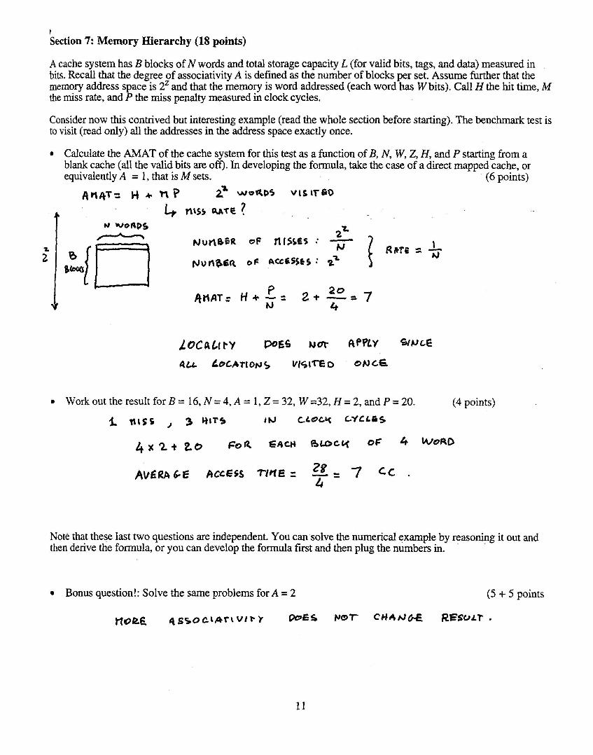
f Section 7: Memory Hierarchy (18 points)
A cache system has B blocks of N words and total storage capacity L (for valid bits, tags, and data) measured in bits. Recall that the degree of associativity A is defined as the number of blocks per set. Assume further that the memory address space is 2' and that the memory is word addressed (each word has W bits). Call H the hit time, M the miss rate, and P the miss penalty measured in clock cycles.
Consider now this contrived but interesting example (read the whole section before starting). The benchmark test is to visit (read only) all the addresses in the address space exactly once.
Calculate the AMAT of the cache system for this test as a function of B, N, W, 2, H, and P starting from a blank cache (all the valid bits are off). In developing the formula, take the case of a direct mapped cache, or equivalently A = 1, that is M sets. (6 points)
Workouttheresu l t forB=16 ,N=4,A=1,Z=32 ,W=32,H=2,~dp=20 . (4 points)
L nrss , 3 I W C L Q C ~ CYCLPS
4 x 2 + 20 FOR EACH R O C & 0: 4
Note that these last two questions are independent. You can solve the numerical example by reasoning it out and then derive the formula, or you can develop the formula first and then plug the numbers in.
Bonus question!: Solve the same problems for A = 2 (5 + 5 points
q s r o c t f i r t ~ i r ~ OOES C H * f J W RESULT.
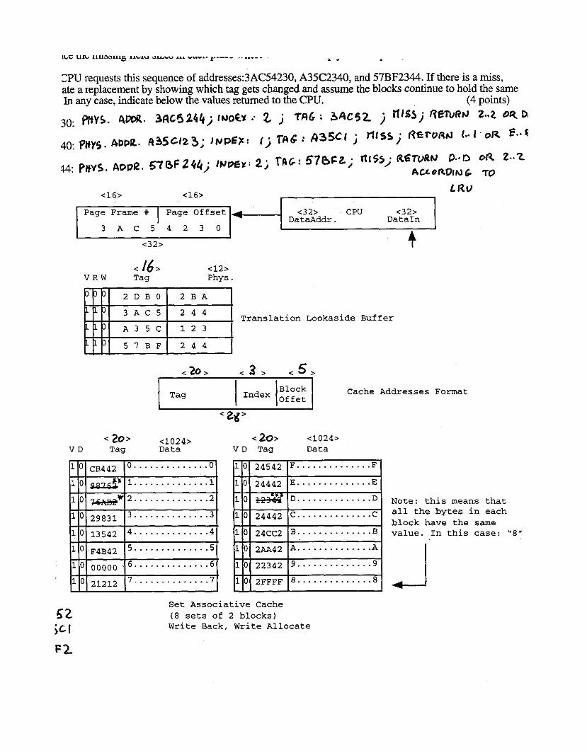
ClPU requests this sequence of addresses:3AC54230, A35C2340, and 57BF2344. If there is a miss, ate a replacement by showing which tag gets changed and assume the blocks continue to hold the same In any case, indicate below the values returned to the CPU. (4 points)
30: r\m. 34c42(4j l ~ o b .. 2 j Tfi6 : 3 A C 5 2 j fl'" j fieTvf?hJ 2.~2 05
, (j r ~ 6 : 4 3 5 C I j Tt fs~ . R € + U R ~ 1 ' OR e.*c 40. pfiY5. 4Pba. 4 3 5 ~ 1 2 3 ; JPPEP. I
</6> <12> V R W Tag Phys .
- - - -
Translation Lookaside Buffer
<32> CPU <32> Da t aAddr . DataIn
< 20 > < 3 > < 5 > -
Block Tag
A
Cache Addresses Format
< 20> <1024> < 20> <1024> V D Tag Data V D Tag Data
Note: this means that all the bytes in each block have the same value. In this case: "8"
Set Associative Cache (8 sets of 2 blocks) Write Back, Write Allocate