˘ ˇ ˆ˙ - core.ac.uk · implications of structural inheritance in oblique rift zones for basin...
TRANSCRIPT
������������������ ��� ��������������������� ��������������������������������� ������ ����������������������������������������������� ������ !�
������������������������������������������������������������������������ �
��������
!��∀��#�∃%#�&��#�∋(#�)���∗#�+(�������,−�∀�������.�,/�−0.�1∀���������������������������������2��3�������∗�������2������∀���∀�����∗�����4�����5����#�!����������,∃(�).��!�������� �&�����∀�6��78#�9/������−−�:−/−��1))4��/0;: −9/�
������ ���7�−��−�−0�<�∀����7��/�−��−/��−
=�/�−0�������∀�������������������∀� ��������2����� ������++:5>:4+:4∋�;������������������������∀∀����7����������28:��:� �;����
�����∀���������#������������������������
������?���������������������������������������
1
Implications of structural inheritance in oblique rift zones for basin
compartmentalization: Nkhata basin, Malawi Rift (EARS).
Mortimer, E. J.1, Paton, D. A.1, Scholz, C. A.2, Strecker. M. R.3
[email protected] corresponding author
1Basin Structure Group, School of Earth and Environment, University of Leeds,
Leeds, UK.2Department of Earth Sciences, Syracuse University, Syracuse, New York 13244.
3Institut f. Geowissenschaften, Universität Potsdam, Postdam, 14476, Germany
Abstract
The Cenozoic East African Rift System (EARS) is an exceptional example of
active continental extension, providing opportunities for furthering our
understanding of hydrocarbon plays within rifts. It is divided into structurally
distinct western and eastern branches. The western branch comprises deep
rift basins separated by transfer zones, commonly localised onto pre-existing
structures, offering good regional scale hydrocarbon traps. At a basin-scale,
local discrete inherited structures might also play an important role on fault
localisation and hydrocarbon distribution. Here, we consider the evolution of
the Central basin of the Malawi Rift, in particular the influence of pre-existing
structural fabrics.
Integrating basin-scale multichannel 2D, and high resolution seismic datasets
we constrain the border, Mlowe-Nkhata, fault system (MNF) to the west of the
basin and smaller Mbamba fault (MF) to the east and document their
evolution. Intra basin structures define a series of horsts, which initiated as
convergent transfers, along the basin axis. The horsts are offset along a NE-
SW striking transfer fault parallel to and along strike of the onshore Karoo
2
(Permo-Triassic) Ruhuhu graben. Discrete pre-existing structures probably
determined its location and, oriented obliquely to the extension orientation it
accommodated predominantly strike-slip deformation, with more slowly
accrued dip-slip.
To the north of this transfer fault, the overall basin architecture is asymmetric,
thickening to the west throughout; while to the south, an initially symmetric
graben architecture became increasingly asymmetric in sediment distribution
as strain localised onto the western MNF. The presence of the axial horst
increasingly focussed sediment supply to the west. As the transfer fault
increased its displacement, so this axial supply was interrupted, effectively
starving the south-east while ponding sediments between the western horst
margin and the transfer fault. This asymmetric bathymetry and partitioned
sedimentation continues to the present-day, overprinting the early basin
symmetry and configuration. Sediments deposited earlier become
increasingly dissected and fault juxtapositions changed at a small (10-100 m)
scale. The observed influence of basin-scale transfer faults on sediment
dispersal and fault compartmentalisation due to pre-existing structures oblique
to the extension orientation is relevant to analogous exploration settings.
Keywords: East African Rift System; structural inheritance; normal fault
evolution; sediment distribution
Introduction
3
Following the margins of the Tanzanian craton, the East African Rift System
(EARS; Figure 1) is divided into two structurally distinct west and east
branches (e.g., Ebinger, 1987). Past tectonic activity since the Proterozoic is
responsible for inducing structural weakness in the lithosphere, which strongly
influences the location and orientation of late-Cenozoic structures in both
branches (Rosendahl, 1987; Versfelt and Rosendahl, 1989; Ring et al., 1992).
The role of inherited structural fabrics, including PreCambrian mobile belts
and Permian Karoo basins is well documented in determining the present-
day structural configuration (e.g., Rosendahl, 1987; Versfelt and Rosendahl,
1989; Morley 1990; Morley et al., 1990; Ring et al., 1992; Corti et al., 2007).
Comprised of a series of opposing, asymmetric, deep half-graben basins
separated by transfer or accommodation zones (Rosendahl, 1987; Ebinger et
al., 1984, 1993; Ebinger, 1989) this part of the EARS highlights the potential
for hydrocarbon trapping where transfers occur (Morley et al., 1990), and can
be likened to those of the Viking graben, North Sea (Scott and Rosendahl,
1989; McLeod et al., 2004).
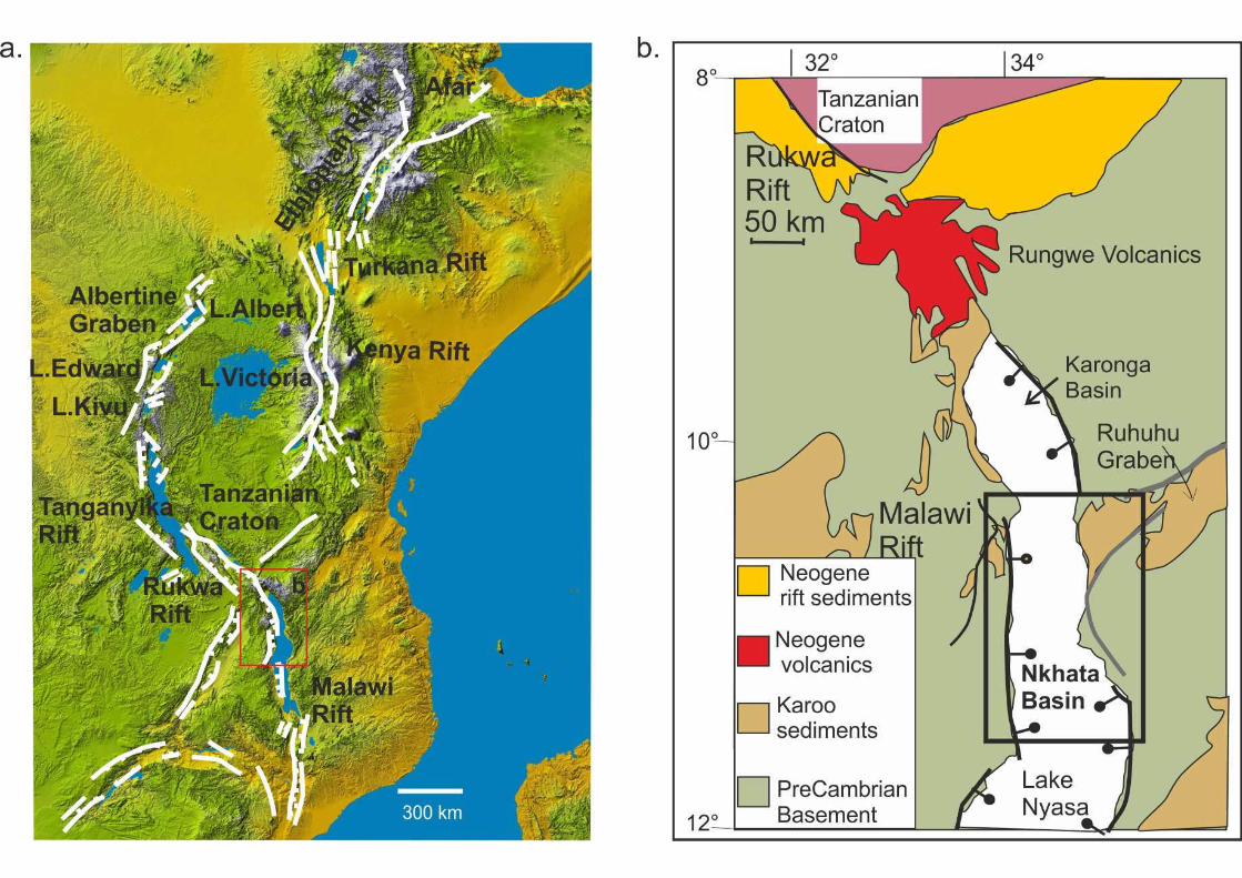
The Malawi rift (Figure 1) is the southernmost rift of the western branch. The
north, Karonga Basin, has undergone oblique extension with a significant
component of dextral slip (Chorowicz and Mukonki, 1980; Wheeler and
Karson, 1989; Wheeler and Rosendahl, 1994) with a temporal variation in rift
obliquity that occurred during the Pleistocene. While initially the region
experienced ENE-WSW oriented extension, the changeover to the
neotectonic kinematic regime has subjected this region to NW-SE extension
(Delvaux et al., 1992; Ring et al., 1992; Scott et al., 1992; Mortimer et al.,

4
2007). This change in stress orientation occurred c. 500 Ka based upon dated
tuffs and the correlation with 100 kyr duration packages in seismic reflection
data (Mortimer et al., 2007). This change in orientation is not, however,
documented to the west of the basin, where Karonga earthquake focal
mechanisms indicate pure extension, and a W-E extension orientation (Biggs
et al., 2012). This change in orientation, while influencing the latest stages of
basin evolution, appears to have been focussed upon the Mbeya region.
Similarly, in the Rukwa basin to the north, stress inversion of earthquakes
(Delvaux and Barth, 2010) shows Sh max is NW-SE, invoking an ENE-WSW
extension regime today.
Existing models for the development of the western branch focus largely at
the rift-scale, with transfer zones that separate basins along the rift providing
predictable regions of potentially good hydrocarbon traps (Morley et al.,
1990). However, in this study we focus on the basin-scale Cenozoic structural
evolution of the c.150 km-long, 40 km-wide central or ‘Nkhata’ (Ebinger et al.,
1987) basin of the Malawi rift which is in part superimposed onto a SW-NE
trending Karoo basin preserved onshore and inferred to continue into the
region currently occupied by Lake Nyasa (Figure 1). It is bounded to the west
by a steep, east-dipping, 120 km border fault system (Mlowe-Nkhata fault)
and to the east by a shorter, ~30 km-long, border fault (Mbamba fault; Figure
2a). Utilizing a close-spaced grid of seismic reflection data, we constrain the
patterns of fault growth and potential role of existing structural trends, and
assess the implications for hydrocarbon prospectivity in this and analogous
basins elsewhere.

5
Data sets, methodology and tectono-stratigraphic framework
Two vintages of seismic reflection data are utilised (Figure 2): (1) 18 basin-
scale multi-channel profiles collected by project PROBE, Duke University
(Scholz, 1989) recording a maximum of 6 seconds (TWT), incorporate the
entire sedimentary fill, and image the top basement reflection; (2) a series of
shallow, up to 2 seconds (TWT), seismic reflection data collected in the late
1990s – 2005 that record the recent basin fill (Scholz, 1995). Seismic profiles
were interpreted using standard seismic sequence stratigraphic methods (e.g.
Mitchum et al., 1977; Hubbard et al., 1985a & b) with Schlumberger Petrel 2D
and 3D environments. Interpreted surfaces were gridded (300 m cell size)
using standard interpolation methods. The resolution and confidence of fault
correlations in map view is a function of line spacing, which, by combining
PROBE and shallow surveys, is reduced to ~1.5 - 8 km in the north and
centre of the basin. In many instances, therefore, faults have been traced to
within 2 km of the fault tip. In the south of the basin, this uncertainty is
increased due to greater line spacing. Variation in sediment thickness,
generated by subtracting interpolated surfaces, has been used to locate the
depocentre for each successive sequence along structures. Depocentre
distribution and evolution provide an approximation for the displacement
pattern, and thus evolution, of faults (e.g., Schlische and Anders, 1996;
McLeod et al., 2000, Contreras et al., 2000; Paton, 2006; Mortimer et al.,
2007).
The established tectono-stratigraphic framework of Scholz (1989) for the
PROBE sequences, namely: 1A, 1B, 2 and 3 (old to young) is used. Ebinger
6
et al. (1993) proposed ages for these sequences based upon the presence of
dated volcanics and unconformities correlated to unconformities interpreted
within the PROBE data that placed the onset of rifting c. 8.6 Ma; Sequence 1-
2 boundary at ~ 2.3Ma and the Sequence 2-3 boundary at ~ 1.6 Ma. It is,
however, likely that the onset of rifting and sedimentation was considerably
earlier than this; with Miocene sediments recorded in the Rukwa Rift to the
north (Roberts et al., 2012) and low temperature thermochronology from the
Livingstone Mountains (Mortimer et al., 2006) suggesting a Miocene onset c.
20 Ma.
The shallow seismic reflection surveys fit within this tectonostratigraphic
context greatly improving the resolution of Sequence 2 and 3, recording the
upper 2 seconds TWT. They reveal high frequency cycles that probably
correspond to ~100 kyr climatic fluctuations (Scholz, 1995). In the following
interpretations, the PROBE data has been used to establish the overall basin
geometry, to create the first-order fault model, and to investigate the earliest
three stages of basin evolution (Sequences 1A, 1B, and Sequence 2). Within
the shallow seismic data, four horizons have been interpreted. The lower
three occur within Sequence 2 and the fourth corresponds to PROBE
Sequence 3. This integration of the two data sets has led to Sequence 2
being sub-divided into 2A (below the shallow seismic data) and 2B, C, D from
oldest to youngest respectively occurring within the shallow seismic data.
Sequence 3 has been described using the shallow seismic data in the north
and central portions of the basin. To the south, PROBE data has been utilised
7
in the absence of shallow seismic data. The shallow seismic data has also
been utilised to refine the fault model.
Nkhata Basin Setting and Architecture
The Nkhata basin is one of the three deep basins of the Malawi rift that
accommodate >4 km sediment, and are connected across transfer, or
accommodation, zones (Ebinger, 1987; Versfelt and Rosendahl, 1989;
Ebinger et al., 1993). Existing structures of significance are the Ubendian
Proterozoic mobile belt, known to have exerted strong influence on the
location and orientation of the northern (Karonga) basin of the Malawi Rift
(Rosendahl, 1987; King, 1994), and later Permian Karoo extensional basins
onto which many basin separating accommodation zones are juxtaposed
(e.g., Versfelt and Rosendahl, 1989) . There are significant occurrences of
Karoo sediments in a SW-NE graben to the east of the central basin of the
Malawi Rift, and some deposits to the west suggesting this graben continues
into the region occupied by Lake Nyasa (Figure 1b).
The northern two thirds of the >700 km Malawi Rift is, today, filled by the 700
m deep Lake Nyasa, at its deepest adjacent to the border faults. The Nkhata
basin is bounded by the Mlowe-Nkhata Fault (MNF) to the west, the Mbamba
Fault to the east, and is dissected by a number of smaller intra-basin faults of
varying length and orientation (Figure 2).
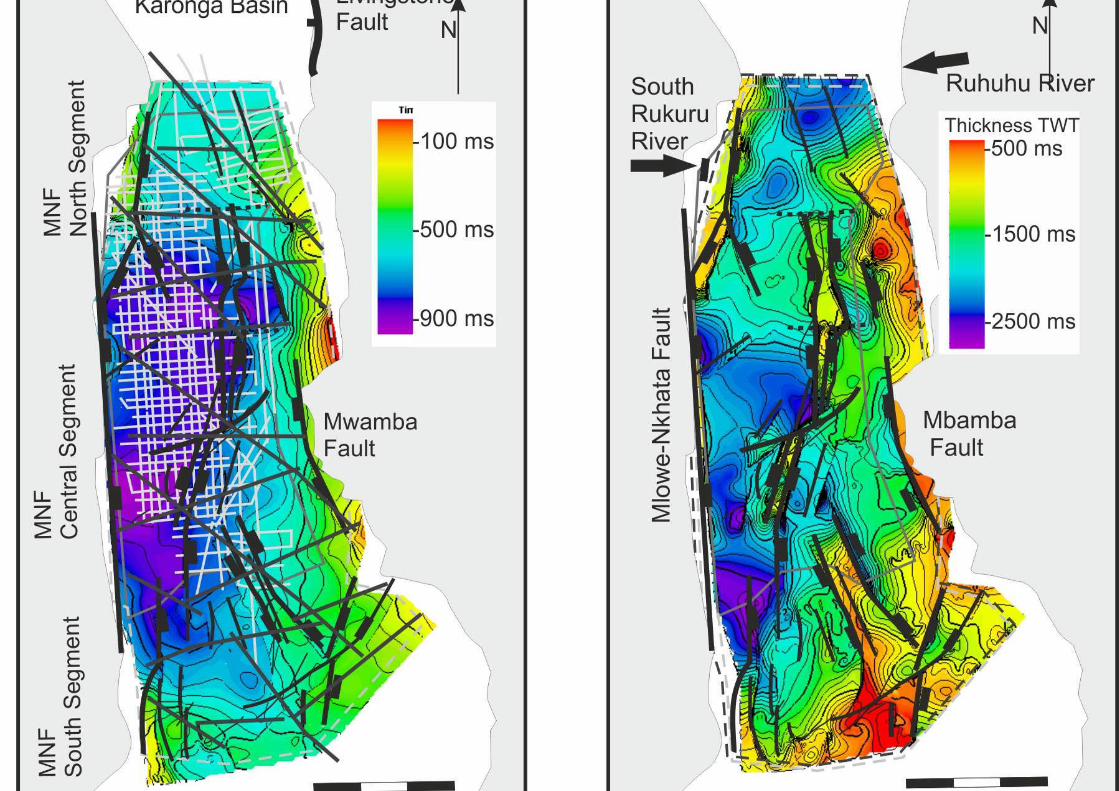
The sedimentary fill of the Nkhata basin thickens westward toward the MNF,
and thins to the southeast. Where the lake floor is deepest (Figure 2a) is
coincident with the thickest sedimentary fill adjacent to the MNF (Figure 2b),

8
at the centre of this fault. The MNF comprises three border fault segments of
40 km, 60 km, and 40 km length, from north to south respectively (Figure 2).
The north and central segments have been recognised by previous
interpretations (e.g., Ebinger et al., 1987; Scholz, 1989; Soreghan et al., 1999;
Contreras et al., 2000), separated by a relay ramp (Chilumba ‘platform’
Scholz, 1989) that is dissected by normal, preferentially SW-dipping faults
(e.g., Soreghan et al., 1999). The south fault segment was first interpreted by
Contreras at al., (2000) based upon PROBE data, however, the greater
resolution of our data indicates that it does not continue so far north into the
basin as they proposed. The central and south fault segment tips, because of
limited data, can only be inferred, but overlap by ~10 km, and are separated
by ~6 km.
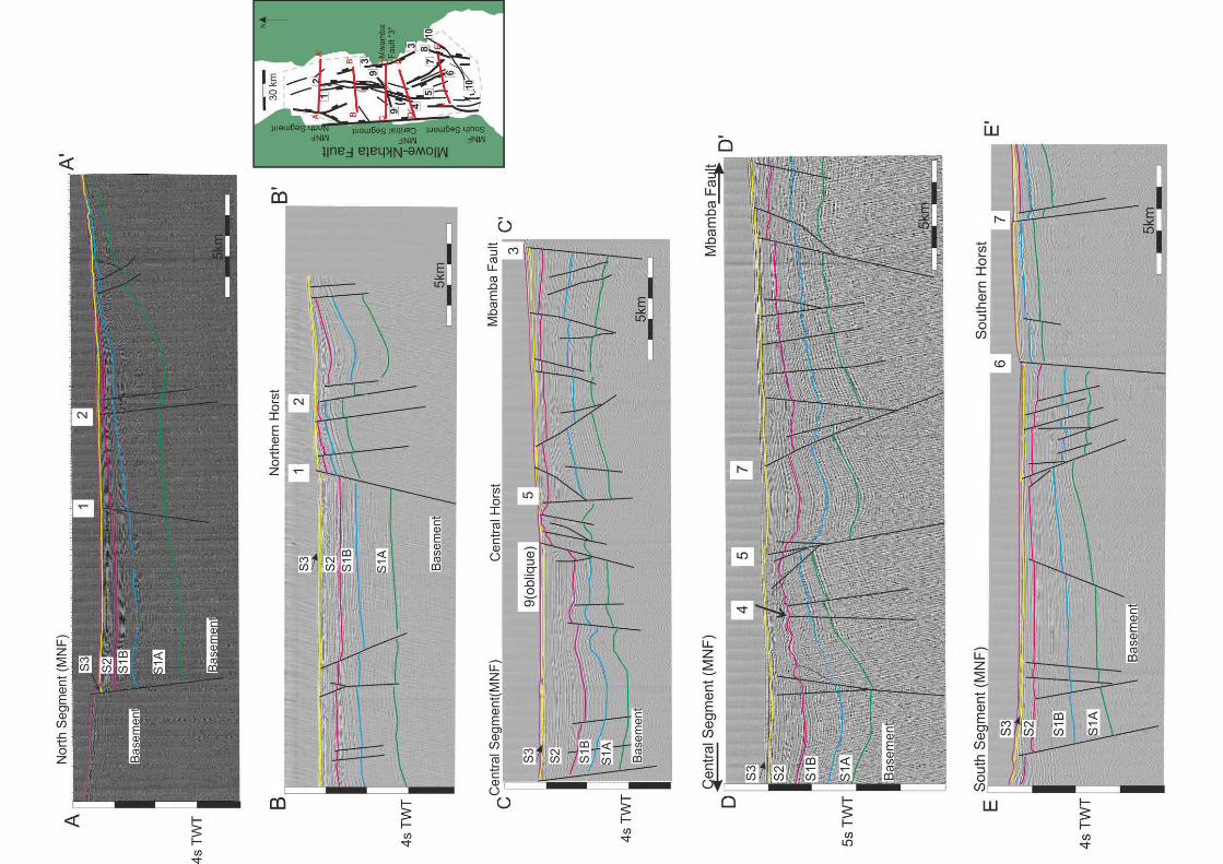
The geometry of the Nkhata basin varies along axis (Figure 3). To the north
(section A-A’) it is an asymmetric half-graben with an eastern shoaling margin.
Toward the centre (sections B-B’ and C-C’), this asymmetry decreases with
the development of a more symmetric graben bounded to the west by the
east-dipping MNF, and by the west-dipping Mbamba Fault to the east with a
horst in the middle of the basin. This horst is offset along strike of the basin,
separated into the ‘north’ and ‘central’ horsts across Fault 9 (discussed later).
The Mbamba Fault is ~30 km and accommodates 1700 ms of sediment in its
hanging-wall. Further south in the basin, the prominence of the central horst
is reduced (section D-D’) and the Mbamba fault to the east is no longer
present. Farther south, heading toward the transfer zone into the southern
basin of the Malawi Rift, the overall geometry is dominated by thickening of
9
the sediments into the MNF and the presence of a separate ‘southern horst’ in
the east of the basin (section E-E’) that has sediments of Sequence 2 either
not deposited or subsequently eroded from its crest.
Within the basin, the architecture is controlled by intra-basin faults with
displacements ranging from seismic resolution to a few 100 ms TWT. As it is
important to correlate faults across the data, only faults with throws > 100 ms
TWT are considered, of which a total of nine (numbered on figures) significant
faults are recognised. The majority of the intra-basin faults strike sub-parallel
to the MNF, although a small number (faults 9 and 10) have a cross-cutting,
NE-SW strike. The basin is divided along its central axis by a series of horsts
(Figures 2 and 3), separating a region of considerably greater sedimentation
to the west from that in the east (Figure 2b; sections B-B’, C-C’, E-E’ Figure
3). Along their strike the horsts are offset by smaller, cross-cutting faults (e.g.,
fault 9; Figure 2; section C-C’, Figure 3).
Nkhata Basin Evolution
The distribution of depocentres (based upon sediment thickness TWT) for
each depositional sequence (Figure 4) has been utilised to reconstruct the
spatio-temporal evolution of the basin. Footwall sediments with the exception
of minor thicknesses (< 50 ms) are generally not preserved along the MNF;
therefore the thickest depocentre is taken to represent the location of
maximum displacement (d-max) along the structure. Within the basin,
sediment thickness (TWT) variations across structures where footwall
sediments are preserved, in addition to the spatio-temporal distribution of
depocentres have been used in determining the evolution of intra-basin faults.

10
Sequence 1A
In the earliest resolvable stages of basin evolution (Figure 4a, Sequence 1A),
the MNF comprised four (rather than the present three) individual segments.
The north and central MNF segments were separate and it is likely they
overlapped. The present-day central segment comprised two segments of
similar length (~25 km) that were separated by a high, while the south
segment was present but exerted little influence on sedimentation. In the east
of the basin, the Mbamba Fault was active along its northern half opposite the
high between the two central fault segments.
Within the basin most sedimentation was accommodated across a small
population of faults striking sub-parallel to the MNF. Those that exhibit
sediment thickening greater than a few hundred ms TWT are Fault 1 (up to
1200 ms TWT) and Fault 5 (>600 ms TWT). These two faults form an
opposing half-graben architecture separated by Fault 9 (which has no
resolvable dip-displacement at this time); and are antithetic to their border
faults the central segments of the MNF (fault 1) and the Mbamba fault (fault
5).
Sequence 1B
In Sequence 1B (Figure 4b) the individual MNF segments each had a
depocentre toward their centre, and the Mbamba Fault accommodated as
much sediment in its hanging-wall as the MNF fault segments, and along its

11
entire length. Overall the basin had a striking disparity between the
asymmetry in the north, and more symmetric graben to the south. The relay
between the north and central fault segments was well established, and
sediments are likely to have been transported along this into the hanging-wall
adjacent to the north segment fault tip where a significant accumulation is
present. The relay represents a high in the basin at this time. Farther south,
the central fault segments are still separated by a high.
Within the basin, the total length of the bounding faults of the three horsts was
achieved (Figures 4a and b) and a number of ‘new’ faults within the horsts
appear (although they may have been present below seismic resolution prior
to this). The northern horst is comprised of four linked faults, two on each
margin, with additional smaller faults between them. These also formed with
an opposing sense of asymmetry across them (Figures 4a and b). Patterns of
sediment distribution along Faults 1 and 2 suggest they had opposing dips
and propagated toward one another to develop a horst with fault 2 being a
younger structure; similarly Fault 4 (antithetic to fault 5, and bounding the
central horst) became active during Sequence 1B. All of Faults 1, 2, 4, and 5
terminate or merge with Fault 9 in the centre of the basin. Fault 4 is antithetic
to the now developing central fault segment as displacement moves toward
the middle of the basin. Both the north and central horst remain asymmetric
across them, and that asymmetric is opposing across Fault 9. The southern
horst was present throughout deposition of Sequence 1, dissected by smaller
faults in Sequence 1A that were inactive by 1B. Fault 10, in the south of the
12
basin appears to truncate the southern horst and behave in a similar manner
to fault 9, although there is poor data resolution in this portion of the basin.
Sequence 2
During deposition of Sequence 2, the relay between the north and central fault
segments was breached (Figure 4c-f) by a number of smaller faults crossing
it. The pattern of sedimentation overall within the basin becomes more
asymmetric thickening to the west into the MNF, with the intra-basin regions
to the east of the horsts experiencing a reduction in sedimentation (aside from
the centre of the basin). The total thickness of Sequence 2 (Figure 4c) shows
the accumulation of sediment on the relay, the individual packages (Figures 4
d-f) highlight the development of NE-SW trending faults across the relay that
at times was bypassed by sediment. It is also during Sequence 2 that the
central fault segment depocentres amalgamated from two separate basins
(Figure 4d and e) that become progressively closer until they merge (Figure
4f) as the central segment became fully linked overprinting the earlier high. As
strain localised onto the MNF, the Mbamba Fault to the east became
significantly less important; and the southern MNF segment became more
active.
The overall pattern of sedimentation within the basin (Figure 4c), shows that
the horsts were established and provided the predominant control on intra-
basin sedimentation: that there is little sediment preserved on their footwalls
suggests these were regions of non-deposition and possibly emergent highs
during lowstand conditions. Overall, the basin is asymmetric with sediments
13
thinning onto the eastern margin as strain had been localised onto the MNF.
Divergent reflections and package thickening indicates significant deposition
in the hanging-wall of Fault 1 (at least 600 ms TWT thickening across the
fault), Fault 5 (c. 700 ms TWT across it), Fault 2 (c. 600 ms TWT) and Fault 4
(600 ms TWT). Fault 6 was also active, with c. 300 ms TWT thickening across
it. Importantly, there is a notable reduction in sediment reaching the south and
east of the basin compared to Sequence 1B; additionally, there is an
accumulation of sediment in the hanging-wall of Fault 9 and 2 east of the
northern horst. The shallow seismic data supplement the PROBE data for the
upper portions of Sequence 2 (Figures 4d,e,f) and show the importance of
Fault 4, 1, 5 and 9 in the distribution of sediment. Of the three Sequences 2B-
D, 2C is likely to represent a period of reduced sediment supply and
concentration of sedimentation adjacent to the border fault. During Sequences
2B and C, however, sediments are deposited across the basin, concentrated
in the hanging-wall of Fault 4, and Fault 9, with small dissected depocentres
developing to the north of Fault 9. To the south east, and into Fault 5,
sediments also accumulated, although notably less than to the west, until
Sequence 2D, where sedimentation to the south east of Fault 9 is significantly
reduced. This coincides with the merging of depocentres on the MNF central
segment, and with increased displacement on Fault 9.
Sequence 3
During Sequence 3 (Figure 4g) the southern segment accommodates similar
sediment volumes to the central segment, from which it is separated by a
probable relay zone, although the absence of high resolution seismic
14
coverage in this region means it cannot be resolved. By the end of Sequence
2 and during Sequence 3, sedimentation was concentrated adjacent to the
central portion of the MNF (Figures 4f and g).
The pattern of sediment distribution within the basin observed for Sequence 2
continues into Sequence 3, where, while the principal structures remain active
(e.g., Faults 5, 2) sediment is focussed adjacent to Faults 1, 9, and 4 within
the basin and along the central MNF fault segment, and to the north of the
basin to a lesser degree. These regions of sediment accommodation are
separated by condensed sections which, where they are pronounced, are
probably also related to a reduction in the lake dimensions; however,
depocentres’ location is structurally controlled. Sediment entering the basin to
the North deposit a delta fan; while those to the west are likely to comprise
both material transported through the relay and some axial transport into the
main depocentre, which exhibits a rapid thickening. In this manner while the
north of the basin has always been asymmetric throughout its history, the
centre of the basin was initially more symmetric with border faults on both
west and east, but became increasingly asymmetric in terms of basin-fill as
strain localised onto the MNF (Figures 4c and d), and it is this latter
asymmetry that is reflected in the present day bathymetry (Figure 2a).
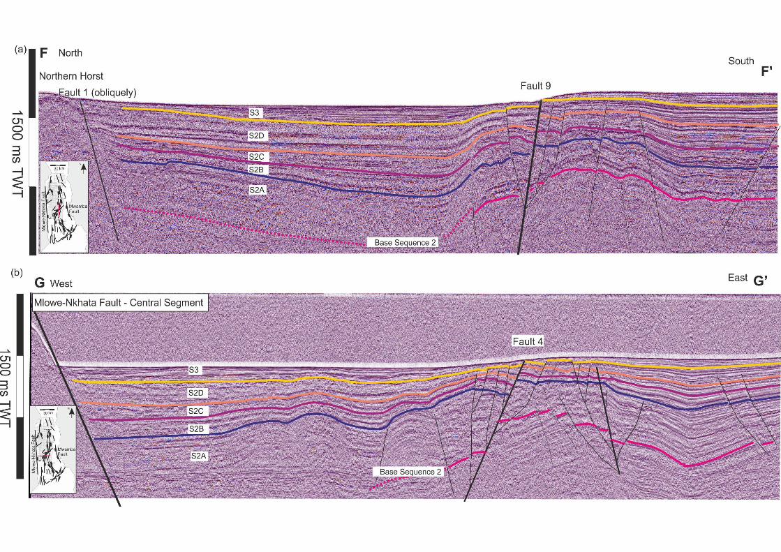
Fault 9
Of the NE-SW striking fault population, Fault 9 (Figure 4) is the best imaged.
In cross section (Figure 5a, Section F-F’) it has a flower geometry, with a
number of smaller dissecting faults affecting the sediments adjacent to it.

15
Fault 9 exhibits no measurable thickening across it during Sequences 1A and
B (Figure 4a and b; PROBE section C-C’ Figure 2); however, it is likely to
have been present as a transfer fault given the opposing sense of dip
between Faults 5 and 1 offset across it. During Sequence 2, a measurable
dip-displacement component to Fault 9 becomes apparent, as its footwall is
uplifted to the southeast during Sequence 2D (Figure 4f; Figure 5a) and
sediment accumulates in its hanging-wall both to the west and east of the
northern horst; and to the west of the central horst. Initially, Fault 9 separated
two opposing half graben, later antithetic faults developed and it separated
the horsts while extension continued. Initially, Fault 1 to the north and Fault 4
to the south of Fault 9 (Figure 5b) accommodated most of the sediments
accumulating along the western margin of the horst, but by Sequence 2C and
2D and into Sequence 3, sediments were accumulating in the hanging-wall of
Fault 9, while Fault 4 was to some degree uplifted in the footwall of Fault 9 as
displacement across Fault 9 increased. This is highlighted in a comparison of
the cross sections F-F’ and G-G’ (Figure 5) where the thickness variation of
Sequence 2 across Fault 4 is seen to decrease significantly above 2C, while it
increases significantly across Fault 9 from Sequence 2C to 3.
Discussion
The border fault system, unlike those to the north (Karonga basin, Mortimer et
al., 2007) is not superimposed upon an underlying Ubendian fabric. The
border fault nucleation and growth through fault tip propagation and linkage
through breaching relay structures between overlapping segments (Trudgill
and Cartwright, 1995) occurred in a manner anticipated for normal fault
systems (Dawers and Anders, 1995; Trudgill and Cartwright, 1995; Gupta et
16
al., 1998; Cowie et al., 2000). This evolution leads to predictable sediment
distribution with deposition progressively focussed toward the centre of the
border fault array as it lengthens (McLeod et al., 2004) as is observed on the
present day central basin (Figures 4 and 5). The Mbamba Fault initially played
an important role in controlling sediment dispersal across the basin. Its
location, directly opposite the central segment of the border fault system
suggests that strain across the central part of the basin was accommodated
on the Mbamba Fault until the central segment of the border fault system had
linked and the full length established during Sequence 2. The Mbamba Fault
is located directly opposite what is now the region of greatest sediment
accumulation and lake depth on the MNF (and the entire basin).
The intra-basin region is dominated in the north and the centre by the
presence of a horst that trends parallel to the MNF, and is offset across Fault
9. Very few faults exist between these larger displacement structures in the
centre of the basin and the border fault, such that by the end of Sequence 1A
strain was already localised into these regions, and the border faults had
already accrued significant displacement. The early development of the horst
region was of opposing half-graben bounded by faults up to 10 km in length
and a few hundred meters of displacement separated across Fault 9 (and
possibly other smaller NE-SW-trending structures) where their fault tips
overlapped or converged. Each major fault (i.e., Fault 1 and 5) was antithetic
to the dominant border fault; which during the early stage of the basin history
included the Mbamba fault to the east. In a similar sense, the northern half of
Fault 2 (later to become the eastern bounding fault of the horst) was
17
propagating with an opposing asymmetry to Fault 1. As the basin evolved, so
the horsts established their length through the development of faults antithetic
to these earlier faults. The pattern of intra-basin faulting for the majority of the
structures striking slightly oblique to the MNF is consistent with modelled rift
basins (Clifton et al., 2000; McClay et al., 2000; Corti et al., 2007) in regions
where the extension direction is slightly oblique with respect to the existing
structural framework. As these internal faults propagated along-strike, internal
regions of the basin became compartmentalized into two areas west and east
of the central horsts.
The flower cross-section geometry of Fault 9 indicates that it is active in a
strike-slip sense, although the duration of fault activity cannot be ascertained.
Its location between two converging intra basin faults (Faults 1 and 5) in the
early stages of basin formation, give rise to a convergent transfer zone in
which Fault 9 is the transfer fault (e.g., Ebinger, 1989; Morley, 1990; Corti et
al., 2007; Debapriya and Shankar, 2013) striking obliquely to the extension
orientation. We suggest that Fault 9, and other similar striking faults within the
basin were active from the earliest stages of basin evolution producing
smaller intra-basin transfer zones, mirroring those larger-scale zones of
accommodation and transfer between the Karonga and Nkhata Basin, and
others along the rift. As extension within the basin continued, so the
component of dip-slip along Fault 9 increased, such that it in turn became a
significant feature affecting sediment distribution within the basin.
Basin summary and synthesis:
18
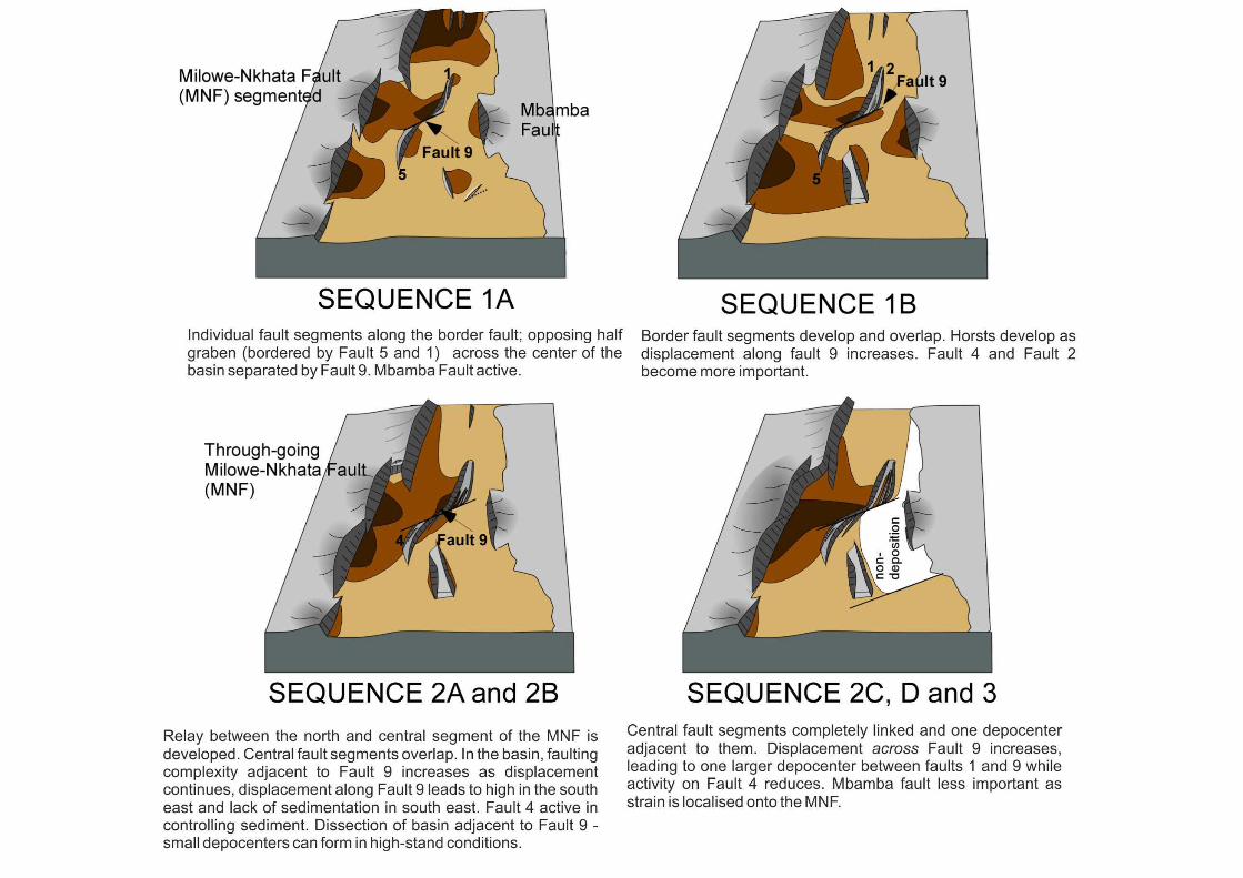
A summary of the basin evolution is presented in Figure 6, and constitutes the
following steps: [1] Sequence 1A: Most of the major faults were established
and the MNF was segmented with a significantly smaller segment to the
south. The Mbamba Fault was similar in scale to the central segments of the
border fault. In the centre of the basin, smaller intra-basin faults striking
parallel to the border fault system formed a convergent transfer zone in the
north separated by Fault 9, while to the south similar structures are observed.
[2] Sequence 1B: the intra-basin horsts are well-defined along the basin axis,
as faults antithetic to the existing structures in the centre of the basin form.
Deposition is focussed adjacent to the MNF and to depocentres along the
west margin of the horst in the north, and across the basin in the centre-south.
[3] Sequence 2A to base 2C: the MNF formed a linked array through the
breaching of relays as the north and central segments linked. The horsts in
the central region were fully established along strike, separating the basin
across west and east. Smaller, new faults develop adjacent to Fault 9 creating
smaller compartments to the north and south as extension across the transfer
continues. At the same time, the basin becomes asymmetric along its entire
length; [4] Sequence 2C-3: the central 2 segments become fully linked with
one depocentre, coupled with a marked reduction in the amount of sediment
accommodated in the hanging-wall of the Mbamba Fault as strain became
localised onto the MNF in the west. Fault 9 accumulated increasing amount of
displacement, while Fault 4 became less important.
The role of the Karoo trend and structural inheritance:
19
To the east of the Malawi basin is the Karoo (Permo-Triassic) Ruhuhu graben;
the northern margin of this system coincides with the rift-scale wide transfer
zone between the north and central basins (Rosendahl 1987; Morley 1990).
The southern boundary of the Ruhuhu graben also strikes parallel to and is
along the fault trace of Fault 9 (Figures 1 and 4 ); and the trend of this
continues to the location of the early basin high between depocentres
adjacent to the central segment of the border fault system.
We suggest that the Ruhuhu graben, or an extension of its associated
structures, controls the location and orientation of Fault 9 within the central
basin. The orientation of such structures may have acted as early rupture
barriers, and influencing the location of fault tips (Mbamba Fault) and segment
boundaries (MNF central segments), which were subsequently overcome.
Additional structures associated with the Ruhuhu graben probably also
determine the location of other NE-SW striking faults within the basin. These
existing structures coupled with the extension orientation are ideal for
localising strike-slip or transfer faults. As previously noted, the geometry of
Fault 9 separating Faults 1 and 5 is reminiscent of regional-scale opposing
half-graben separated by accommodation zones localised onto existing
structures (e.g., Versfelt and Rosendahl, 1989), but occurs here at the basin-
scale. Not only, therefore, are existing earlier extensional structures important
at the rift scale, they are important in determining the further differentiation
and internal architecture of individual rift basins (Corti et al., 2007). To the
south of the basin, Fault 10 follows a similar structural trend and coincides
with the start of the wide transfer zone between the Nkhata and southern
20
basins. Thus existing pre-Cenozic structures have controlled the location of
intra-basin transfer zones that become increasingly important as the amount
of dip-slip across them accrues. This contrasts strongly with the asymmetric
Karonga basin to the north, which does not experience the influence of
underlying Karoo fabrics to the same effect, nor contains transfer faults within
the basin (Mortimer et al., 2007).
Sediment distribution and hydrocarbon implications
This pattern of fault evolution has led to more complex sediment distribution
and later dissections than might be anticipated. There are two main points of
sediment entry into the Central basin: the Rukuru river (and delta) that enters
the basin along the central border fault segment through the relay structure;
and the Ruhuhu river which enters along the Ruhuhu Graben (Figure 7).
During the early Sequences of deposition (Sequence 1A and B) sediments
were relatively well distributed across the basin (Figure 4a-b); however in later
sequences (from Sequence 2, Figures 4c-g) the east of the basin becomes
increasingly comparatively starved, and in places would likely have been
exposed during lake-level lowstand. This is especially pronounced by
observing the distribution of sediment during Sequence 2B (Figure 4e) and
Sequence 3 (Figure 4g). There is unlikely to have been significant transfer of
coarse grained sediment from the western margin toward the east due to the
presence of the linked horsts along the axis of the basin from Sequence 2A.
Additionally, displacement across Fault 9 led to a reduction in the transport
south along the eastern margin of the horst, and created a ponding effect to
21
the west of the horst, leading to a tongue of sediment being transported into
the region between Fault 1 and 9 (Figure 4d-g).
During Sequence 2, as the oblique-slip extension across Fault 9 increased
and Faults 1 and 5 separated further, new, smaller faults dissect the region
immediately adjacent to Fault 9 and the earlier depocentres associated with
the major intra-basin faults. This leads to a highly compartmentalized
depocentres adjacent to the transfer fault.
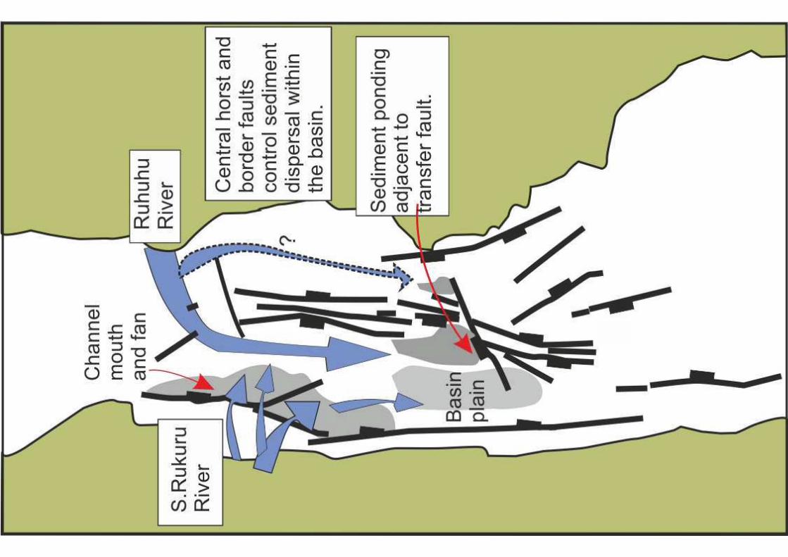
Soreghan et al (1999) have well documented the distribution of sediments
along the western part of the central basin. They record a channel network
both through the relay zone (Rukwa River) and an additional channel from the
Ruhuhu graben into the central part of the basin (Figure 7). Wells et al. (1995)
and Soreghan et al (1999) show that coarse-grained material deposited
dominantly in gravity driven flows accumulate on the relay ramp during
highstands but otherwise are transported through canyons to the offshore
area adjacent to the tips of the overlapping fault segment . The systems in the
intra-basin region are confined by the western margin of the horst structures
defined in our study. Similarly, a channel they document entering the basin
from the north must flow around the propagating tip of the northern extent of
the central horst system documented here. They observe that the coarsest
material is ponded adjacent to the bounding and principal controlling
structures as might be anticipated. This pattern of distribution for the latest
stages of deposition is closely related to the present day fault configuration.
Earlier deposition was better distributed to the east and along-axis before the
22
full linkage of the horst structures and significant displacement accumulation
on or associated with Fault 9.
Implications for petroleum systems:
Intra-basin structures have been shown to exert an important influence on the
evolution, sedimentary facies distribution and hydrocarbon trapping in rift
basins (e.g. Bartholomew et al., 1993; Erratt et al, 1999; Whipp et al., 2014)
and passive margin rift systems are dissected by cross cutting faults, in a
similar geometry observed in Malawi (Paton et al., 2008, Tsikalas et al., 2008;
Antobreh et al., 2009; Heine et al., 2013). Often these structures are not well
defined as a consequence of poor quality data, wide spacing of available 2D
lines, or a sub-salt setting. Understanding their role is of particular importance
in frontier areas where 2D data is utilised. Our findings in the Malawi Rift can
be applied to rift basin exploration elsewhere, in particular in highlighting the
importance of underlying structures in controlling the initial intra-basin fault
behaviour and predicting their effect on sediment transport and basin
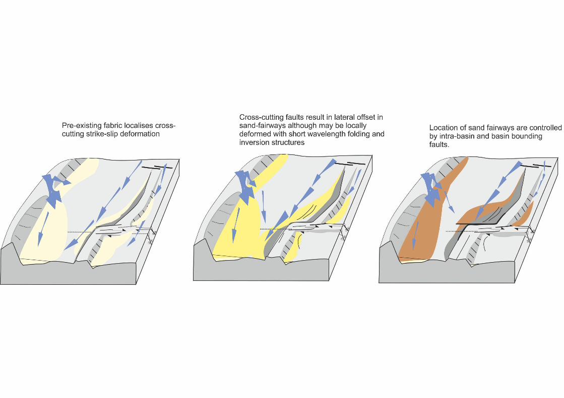
architecture (Figure 8).
The scenario outlined here, in which there is a fabric cross-cutting the main rift
geometry allows us to make some key predictions: the principal intra-basin
faults are approximately co-linear and grow through time. This results in
relatively linear axial sand fairways controlled by intra-basin faults. The cross-
cutting faults are active as transfer faults likely to cause localised deflection of
the fairway and result in a oblique stacking pattern of channel systems at the
step-over zone. As dip-slip displacement accumulates on the developing

23
structure, so sediment pathways are disrupted and sediment ponding occurs,
while dissection of existing depocentres continues as the lateral offset along
the cross-cutting structures increases.
This has two implications: (1) fairway distribution may be controlled less by
the main intra-basin faults, while local depocentres at accommodation zones
may occur; and (2) previously continuous sand fairways that were migration
pathways for charge from the down-dip kitchen to up-dip flanks, become
highly compartmentalized while juxtapositions across the structures change
significantly.
Acknowledgements
Funding for EM was provided by DFG grant STR 373/15-1 and by the Basin
Structure Group at the University of Leeds. Support for the field acquisition of
single-channel seismic reflection data was provided by the Industrial
Associates of the Lacustrine Rift Basin Research Program at Syracuse
University, C. A. Scholz, Principal Investigator. Multichannel seismic
reflection data was acquired under the auspices of Project PROBE at
Duke University, under the direction of B. R. Rosendahl.
24
References
Antobreh, A.A; Faleide, J.I ; Tsikalas, F. ; Planke, S., 2009, Rift-shear
architecture and tectonic development of the Ghana margin deduced from
multichannel seismic reflection and potential field data: Marine and Petroleum
Geology v.26, p.345-368.
Bartholomew, I. D, Peters, J. M. Powell, C. M., 1993, Regional structural
evolution of the North Sea: oblique slip and the reactivation of basement
lineaments: Petroleum Geology Conference series, v.4, p.1109-1122,
doi:10.1144/0041109.
Biggs, J., Nissen., E., Craig, T., Jackson, J., Robinson, D.P., 2010, Breaking
up the hanging wall of a rift border fault: the 2009 Karonga earthquakes,
Malawi. Geophysical Research Letters, v.37:L11305.
Clifton, A.E., Schlische, R.W., Withjack, M.O., and Ackermann, R.V., 2000,
Influence of rift obliquity on fault-population systematics: results of
experimental clay models: Journal of Structural Geology, v.22, p.1491-1509.
Contreras, J., Anders, M. H. & Scholz, C. H., 2000, Growth of a normal fault
system: observations from the Lake Malawi basin of the east African rift:
Journal of Structural Geology, v.22, p.159-168.
25
Corti, G., van Wijk, J., Cloetingh, S., Morley, C.K., 2007, Tectonic inheritance
and continental rift architecture: Numerical and analogue models of the East
African Rift system: Tectonics, v. 26, n.6, doi:10.1029/2006TC002086.
Cowie, P.A., Vanneste, C., and Sormette, D., 1993, Statistical physical model
for the spatio-temporal evolution of fault: Journal of Geophysical Research,
v.98, p. 21809-21821.
Cowie, P. A., Gupta, S., and Dawers, N.H., 2000, Implications of fault array
evolution for syn-rift depocentre development: insights from a numerical fault-
growth model: Basin Research, v. 12, p. 241-261.
Dawers, N.H., and Anders, M.H., 1995, Displacement-length scaling and fault
linkage: Journal of structural Geology, v.17, p.607-614.
Delvaux, D.,and Barth, A., 2010, African stress Pattern from formal inversion
of focal mechanism data. Implications for rifting dynamics. Tectonophysics,
v.482, p. 105-128.
Delvaux, D., Levi., K., Kajara., R. & Sarota, J., 1992, Cenozoic paleostress
and kinematic evolution of the Rukwa-north Malawi rift valley (EARs): Bull.
Cent. Rech. Explor. –prod Elf Acquitaine, v. 16, p. 383-406.
26
Ebinger, C. J., Deino, A. L., Tesha, A. L., Becker, T: & Ring, U., 1993,
Tectonic controls on rift basin morphology: evolution of the Northern Malawi
(Nyasa) rift: Journal of Geophysical Research, v.98, p.17821-17836.
Ebinger, C. J., Rosendahl, B. R. and Reynolds, D. J., 1987, Tectonic model of
the Malawi rift, Africa: Tectonophysics, v.141, p.215-235.
Ebinger, C. J., Crow, M. J., Rosendahl, B. R., Livingstone, D.A. and Le
Fournier, J., 1984, Structural evolution of Lake Malawi, Africa: Nature, v.308,
p.627-629.
Errat, D., Thomas, G.M., and Wall, G.R.T., 1999, Regional syntheses,
tectono-stratigraphic analyses and structural studies: The evolution of the
Central North Sea Rift : Petroleum Geology Conference series, v.5, p.63-82,
doi:10.1144/0050063
Flannery, J.W. & Rosendahl, B.R., 1990, The seismic stratigraphy of Lake
Malawi: implications for interpreting geological processes in lacustrine rifts:
Journal of African Earth Science, v.10, p.519-548.
Gupta, S., Cowie, P.A., Dawers, N.H, & Underhill, J.R, 1998, A mechanism to
explain rift-basin subsidence and stratigraphic patterns through fault array
evolution: Geology, v. 26, p. 595-598.

27
Heine, C., Zoethout, J., and Muller, R. D., 2013, Kinematics of the South
Atlantic rift, Solid Earth, v.4, p.215–253
Hubbard, R.J., Pape, J. & Roberts, D.G., 1985a, Depositional sequence
mapping as a technique to establish tectonic and stratigraphic framework and
evaluate hydrocarbon potential on a passive continental margin, in Beerg,
O.R. and Wooverton, D.G ed, Seismic stratigraphy II: AAPG Memoir 29,
p.79-92.
Hubbard, R.J., Pape, J. & Roberts, D.G (1985b), Depositional sequence
mapping as a technique to establish tectonic and stratigraphic framework and
evaluate hydrocarbon potential on a passive continental margin, in, Beerg,
O.R. and Wooverton, D.G ed, Seismic stratigraphy II: AAPG Memoir 29, p
93-116.
Mitchum, R.M. Jr, Vail, P.R. and Sangree, J.B., 1977, Seismic stratigraphy
and global changes of sea-level part 6: seismic stratigraphic interpretation
procedure, in, Payton, C.E. ed, Seismic stratigraphy- applications to
hydrocarbon exploration: APPG Memoir, 26, p 117-134.
McClay, K.R., Dooley, T., Whitehouse, P. & Mills, M., 2002, 4-D evolution of
rift systems: Insights from scale physical models: Bulletin of the American
Association of Petroleum Geologists, v. 86, p. 935-959.
28
McLeod, A.E., Dawers, N.H., & Underhill, J.R., 2000, The propagation and
linkage of normal faults: insights from the Strathspey-Brent-Statfjord fault
array, northern North Sea: Basin Research, v.12, p.263-284.
Morley, C.K., 1995, Developments in the structural geology of rifts over the
last decade and their impact on hydrocarbon exploration, in, Lambaise, J.J.
ed., Hydrocarbon habitat in rift basins: Geological Society Special Publication,
v.80, p. 1-32.
Morley, C.K., Nelson, R.A., Patton, T.L., and Munn, S.G., 1990, Transfer
Zones in the East African Rift System and Their Relevance to Hydrocarbon
Exploration in Rifts (1): AAPG Bulletin, v. 74, n. 8, p.1234-1253
Mortimer, E.J., Paton, D.A., Scholz, C.A., Strecker, M.R., and Blisniuk, P
2007, Orthogonal to oblique rifting: effect of rift basin orientation in the
evolution of the North Basin, Malawi Rift, East Africa: Basin Research, v.19,
n.3, p.393-407, DOI: 10.1111/j.1365-2117.2007.00332.x
Mortimer, E.; Foeken, J.; Strecker, M.; Stuart, F., 2006, Evolution of a Young
Rift Border-Fault System Constrained by Low Temperature (U-Th/He)
Thermochronometry: North Basin, Malawi Rift, East Africa, abstract , AGU
Fall Meeting.
Paton, D.A., 2006, Influence of crustal heterogeneity on normal fault
dimensions and evolution: southern South Africa extensional system: Journal
of Structural Geology, v.28, p.868-886.

29
Paton, D.A., van der Spuy, D, di Primio R., Horsfield, B., 2008, Tectonically
induced adjustment of passive-margin accommodation space; influence on
the hydrocarbon potential of the Orange Basin, South Africa: AAPG Bulletin,
AAPG Bulletin, v.92, p.589–609.
Prosser, S., 1993, Rift-related linked depositional systems and their seismic
expression, in, Williams, G.D. and Dobb, A. ed., Tectonics and seismic
sequence stratigraphy: Special publication of the Geological Society, London,
v.71, p.35-66.
Reynolds, D.J., and Rosendahl, B.R., 1984, Tectonic expressions of
continental rifting: EOS, Trans AGU, v.65 , p.1116.
Reinecker, J., Heidbach, O., Tingay, M., Sperner, B. & Müller, B., 2005, The
release 2005 of the World Stress Map (available online at www.world-stress-
map.org)
Ring, U., Betzler, C., and Delvaux, D, 1992, Normal vs. Strike-slip faulting
during rift development in East Africa: the Malawi rift: Geology, v.20, p.1015-
1018.
Ring, U., Betzler, C., and Delvaux., D, 1992, Normal vs. Strike-slip faulting
during rift development in East Africa: the Malawi rift: Geology, v.20, p.1015-
1018.

30
Roberts, E.M., Stevens, N.J, O’Connor, P.M., Dirks P.H.G.M., Gottfried, W.C.,
Clyde, W.C., Armstrong, R.A., Kemp, A.I.S., Hemming, S., 2012, Initiation of
the western branch of the East African Rift coeval with the eastern branch:
Nature, v.5, p.289-294.
Rosendahl, B.R., 1987, Architecture of continental rifts with special reference
to East Africa: Annual Review of Earth Planetary Science, v.15, p.445-503.
Scott, D. L., Etheridge, M.A., and Rosendahl, B.R., 1992, Oblique-slip
deformation in extensional terrains: a case study of the lakes Tanganyika and
Malawi rift zones: Tectonics, v.11, p.998-1009.
Scholz, C. A., 1995, Seismic stratigraphy of an accommodation-zone margin
rift-lake delta, Lake Malawi, Africa, in, Lambiase, J.J, Hydrocarbon Habitat in
Rift Basins: Geological Society Special Publication, v.80, p.183-195.
Scholz, C.A.,1989, Project PROBE geophysical atlas series, Duke University,
Durham, N.Carolina.
Schlische R.W. and Anders, M.H., 1996, Stratigraphic effects and tectonic
implications of the growth of normal faults and extensional basins: Geological
Society of America Special Paper, v.303, p.183-203.
31
Soreghan, M.J., Scholz, C.A., and Wells, J.T., Coarse-grained deep-water
sedimentation along a border fault margin of Lake Malawi, Africa: seismic
stratigraphic analysis. Journal of Sedimentary Research, 69, 1999, 832-846
Trudgill, B. and Cartwright, J., 1994, Relay-ramp forms and normal-fault
linkages, Canyonlands National Pak, Utah: Bulletin of the Geological Society
of America, v.106, p.1143-1157.
F. Tsikalas, J.I. Faleide, and N.J. Kusznir, 2008, Along-strike variations in
rifted margin crustal architecture and lithosphere thinning between northern
Vøring and Lofoten margin segments off mid-Norway: Tectonophysics, v.458,
p.68-81.
Versfelt, J. and Rosendahl, B.R., 1989, Relationships between pre-rift
structure and rift architecture in Lakes Tanganyika and Malawi, East Africa:
Nature, v.337, p.354-357.
Wells, J.T., Scholz, C.A., and Soreghan, M.J., Processes of sedimentation on
a lacustrine border-fault margin: interpretation of cores from Lake Malawi,
East Africa. Journal of Sedimentary Research, 69, 1999, 816-831.
Wheeler, W. H. and Rosendahl, B.R., 1994, Geometry of the Livingstone
Mountains Border-fault, Nyasa (Malawi) Rift, East Africa: Tectonics, v.13, p.
303-312.

32
Wheeler, W.H., and Karson, J.A., 1989, Structure and kinematics of the
Livingstone mountain border-fault zone, Nyasa (Malawi) rift, south-western
Tanzania: Journal of African Earth Sciences, v. 8, p.393-414.
Withjack, M.O. and Jamison, W.R., 1986, Deformation produced by oblique
rifting: Tectoniphysics, v.126, p.99-124.
Whipp, P.S., Jackson, C. A-L., Gawthorpe, R. L., Dreyer, T., and Quinn, D.,
2014, Normal fault array evolution above a reactivated rift fabric; a subsurface
example from the northern Horda Platform, Norwegian North Sea: Basin
Research, v.26, p.523-549.
FIGURE CAPTIONS
Figure 1: a) The location the Malawi Rift, the southernmost portion of thewestern branch of the East African Rift System; (b) Simplified geology of thenorthern Malawi Rift region extending to the Rukwa Rift ; with the study areaoutlined in the black box.
Figure 2 a) Two Way Travel Time (ms TWT) map to lake bed within theNkhata Basin, seismic reflection data of the PROBE study (1989) shown insolid dark grey lines, shallow seismic reflection data in solid pale grey lines.Principal structures identified within the seismic reflection data are indicated inblack with ticks on the downthrown side; b) Isopach (thickness TWT) map ofthe sedimentary fill of the Central Basin with principal structures shown. Thepoints of entry of the principal sediment sources (the South Rukuru and theRuhuhu Rivers) are indicated.
Figure 3: Cross-sections through the Nkhata Basin showing the principlestructures from north to south. In the north, close to the transfer to theKaronga Basin, the Nkhata Basin is strongly asymmetrical thickening to thewest into the north segment of the Mlowe-Nkhata Fault (MNF) and shoaling tothe east. This asymmetry remains, but is less pronounced as we move to thesouth in section B-B’ but with the addition of the Northern horst dividing the
33
basin. In the centre of the basin adjacent to the central segment of the MNFthe basin the geometry is more symmetrical with a central horst and similardepth to basement on both the east and west margins, in particular adjacentto the Mbamba Fault in Section C-C’. Sedimentation across the horsts isasymmetric, with the west (MNF side) accommodating more sediment.Further south, there is a subtle high adjacent to the MNF in section D-D’corresponding to the region of overlap between the central and southernsegments. In the far south of the basin, the geometry is again of a horst-graben with fault 6, west-dipping and bounding the southern horstaccommodating a similar amount of displacement as the southern segment ofthe east-dipping MNF.
Figure 4: TWT Isopach maps of the Central Basin for each depositionalsequence. PROBE data has been used for Sequence 1 (A and B). Shallowseismic reflection data were used for Sequences 2B,C and D whereas thetotal Sequence 2 (A-D) is the thickness of the entire Sequence present withinthe PROBE data (base Sequence 2 not present in the shallow). Sequence 3is from the shallow seismic data (where present) supplemented by thePROBE data. See inset for outline of PROBE and shallow data coverage; andfor fault numbers as discussed on the figure and in text. These maps showthe migration of depocentres through time adjacent to the MNF and otherfaults. The MNF initially comprised 4 fault segments; the central two linking toform a single fault segment. Fault 9 is discussed in detail in the text, but hasan important role in partitioning the basin; initially positioned along-trend fromthe structural high separating depocentres on the central MNF segment, andin ponding sediment in its hanging-wall (north) preventing sediment transportto the south and east of the basin. Faulting adjacent to fault 9 increases incomplexity throughout Sequence 2, and in Sequence 3, folding occursadjacent to the central MNF. These maps highlight the small-scale intra-basinpartitioning
Figure 5: These sections, which most closely relate to PROBE section C-C’(see Figure 2), show the more detailed fault architecture associated with Fault9. (top) F-F’ cross-section through Fault 9 in the centre of the basin, showingthe geometry of the fault and accommodation in its hanging-wall, in particularduring the later stages of Sequence 2. (bottom) G-G’ cross-section west-eastacross the basin through Fault 4 that connects to Fault 9 just to the north ofthis section.Comparing these two sections highlights the similar structural style betweenthem. It also shows the present day structural high associated with Fault 9and adjacent faults that is important in sediment dispersal, particularly duringlake-level fluctuations, and in influencing the distribution of sequences 2D and3. Fault 9 accommodates more sediment in Sequences 2C-3 while Fault 4was more important early in Sequence 2: from 2A to the base of 2B.
Figure 6: The proposed development of the Central Basin. Faults arenumbered where referred to in the text and are shaded with dark grey on theirfault scarps. Depocentres are shaded, deep brown representing the thickestregion of sediment accumulation within the sequence.

34
Figure 7: Present day fault sediment dispersal within the northern part of theCentral basin (after Soreghan et al., 1999 solid channels; and inferred,dashed channels) and the influence of the intra-basin structures from thisstudy. The relay structure on the border fault system is important for sedimentdispersal into the central segment, and in fans along the north segment. In thecentre of the basin, sediments are transported along strike parallel to the horststructure and are ponded adjacent to fault 9. This is a region with abundantsmall-scale faulting. Very little sediment enters to the east of the central horst.
Figure 8: The influence of cross cutting structures within the rift basin on sandfairway distribution. Importantly for the EARS charge and migration occursinto the present day and will be most affected by the present dayconfiguration, while fairway and reservoir distribution will have beendetermined by the primary basin structures. Initially (1) the transfer fault haslittle displacement, adjacent faults have individual depocentres controllingearly syn-rift sedimentation and sediment pathways exist along-axis of thebasin. (2) as the transfer fault offset continues, displacement along thestructure begins to restrict sediment pathways, while depocentres along theconnecting normal faults enlarge until (3) displacement within the hanging-wall of the transfer fault is significant, leading to ponding of sediment betweenthe rift faults and transfer fault. This will become more pronounced duringperiods of lake-level lowstand (as commonly experienced within EARS lakes).The hydrocarbon consequence of this is twofold: Firstly, the sand fairwaybecomes segmented, with an up-dip charge this would result in eitherreservoir compartmentalization or at least baffling. Secondly, faults with thelargest present day throw may not have been present during deposition ofsyn-rift sand, therefore their location may be misleading.