contents · contents • ict ... sk hynix)isinac@ve)cooperaonwithallecosystem)partners dram(tsvchip...
TRANSCRIPT

1 Mem
con2
015
Sant
a C
lara
Contents
• ICT & Requirements -‐ Shi& from IoT to IoE: What is the Difference? -‐ IoE-‐Based Keywords: Connec?vity, Convergence & Intelligence
• Benefits of HBM -‐ Higher BW, Lower Latency, Lower Power & Small Form-‐Factor
• Dynamics of HBM -‐ Architecture Projec?on & Industry Trends
• Readiness, Achievement, Posi@oning and Strategy of SKH
• Conclusion

2 Mem
con2
015
Sant
a C
lara
ICT & Requirements

3 Mem
con2
015
Sant
a C
lara
The New Big Thing – IoT & IoE
Connected Device Market Explosion enabled by “IoT Boom” Growth of Revenue led by Smart Home, Automo@ve & Wearable Market
(Source: Cisco 2014 )
(unit : billion)
Y2003 Y2008 Y2010 Y2015 Y2020
50
40
30
20
10
0 7.6B
Cross-‐over Devices > World Popula4on
Smart Things
50B
World Popula@on
<Connected Devices per Person>
vs. 0.08 in 2003 6.58 in 2020
Connected Devices IoT-‐Based Semiconductor Revenue
-
500
1,000
1,500
2,000
2013 2014 2015 2016 2017 2018
Digital Set-Top Box
Smart TV
Automotive(Infotainment)
Wearable Device
Healthcare-Monitoring
(Source: Gartner, 2014)
(Unit : USD million)
Electronic Equipment CAGR 2013-2018 (%)
Digital Set-Top Box 21.3
Smart TV 10.6
Automotive(Infotainment) 69.9
Wearable Device 153.1
Healthcare-Monitoring 134.6

4 Mem
con2
015
Sant
a C
lara
Communica@on Direc@on and Opera@on
Clear Differences between IoT and IoE have Appeared During the Past Years
People to People (P2P)
Machine to Machine (M2M)
People to Machine (P2M)
Process
M2M
P2P
M2P
Process
IoE (Internet of Everything)
• Mobility • Security • Borderless NTW
• Cloud • Ver@cal Solu@ons • Social Media
• Data Center • Big Data • Cloud
(Source: Cisco)
Moving From IoT to IoE: “Most Effec@ve Way in Gathering and Analyzing Masses of Data”

5 Mem
con2
015
Sant
a C
lara
IoE-‐Based Keywords
Dissemina@on of connected devices on the basis of users centered interac@on leads to the evolu@onary shie of IoT to IoE
Connec@vity Convergence Intelligence Network + Special Device Open PlaGorm Sensing + Big Data
PC Things
IoT
Device, Func@on and Specifica@on for General Purposes
§ Increase of Devices & Special Devices (Smartwatch, glass, band...) § Evolu@on of Func@on, Specifica@on, Design and User Experience
“User-‐Unfriendly”
§ User-‐Friendly & User-‐centered Interac@on § Breakthrough in Recogni4on technology (e.g. Touch, Voice, Gesture, Biometrics) § Specialized Applica@ons, Services, Wireless Internet, Mobile-‐Based Service Expansion
Monopoly, e.g. Intel CPU, MS OS à Limita@on of Compe@@ve Factors Differen@a@on from Manufacturers’ Perspec@ve
§ Compe@@veness Diversifica@on by Product porkolio, Connec@vity between Devices, OS Plakorm Compe@@veness § Securement of Strong Posi@oning as a Compe@@ve Advantage in a Variety of Elements Made Possible à Importance of Ecosystem Approach
IoE
Device Features
User-‐Based
Values
Major Compe44ve facto
rs

6 Mem
con2
015
Sant
a C
lara
Requirements – Changes & Prepara@ons
System Requirements: Mobility Performance, Thin & Light Devices & Longer Balery Performance Memory Requirements: High Speed, Low Latency, High Density & Low Power
DRAM Scaling Limits
ICT Trend & Value-‐chain
Big Data
IoT, IoE
Data in Mo?on
Analy?cs
Simultaneous Prepara4ons
Data Center Traffic 3.1ZB @’13 à 8.6ZB @’18 (CAGR23%)
Ver8cal Integra8on toward Service-‐centric Industry
2006 (~um) 2016(1x nm)
~9$
~0.x$ # of Process Steps CAGR < 5%
# of Process Steps CAGR > 5%
ASP CAGR -‐30% (1Gb Eq.)
Following scalability requirements of system through exis?ng
infrastructure
à DDR4E, P-‐DDR4, P-‐LPDDR4
Mee?ng future system performance requirements through Architect
ure Breakthrough
à Total Op@miza@on à Memory Hierarchy Tiering à Stacking Technology
Evolu4onary
Revolu4onary
Database Servers In-‐Memory Compu?ng
System Architecture
HPC Memory Bandwidth/node 100~500GB/s @’15 à 2~4TB/s @’19
Compu?ng Intensive Data Intensive
Data
?
Memory Hierarchy
simultaneous Changes
Networks
Role-‐Sharing between Memory Solu@ons: B/W vs. Capacity
HBM* (B/W)
MDS** (Capacity)
* HBM: High Bandwidth Memory ** MDS: Managed DRAM Solu@on
Query
+ +
Technology Complexity ∝ CAPEX

7 Mem
con2
015
Sant
a C
lara
Benefits of HBM

8 Mem
con2
015
Sant
a C
lara
Higher Bandwidth
Lower Speed Per Pin (2Gbps) è 𝟐/𝟕 of GDDR5 Higher Bandwidth Per Chip (256GB/s) è x9.1 higher than GDDR5
2.0
3.2
7.0
1.0
DDR3 DDR4 GDDR5 HBM2
[Gbps/Pin]
4.0 6.4 28
256
DDR3 DDR4 GDDR5 HBM2
[GBps/Chip]
HBM2 HBM2
x9.1
Speed Per Pin Bandwidth Per Chip
x2/7

9 Mem
con2
015
Sant
a C
lara
Lower Latency
Pseudo Channel Mode @ HBM2 è x4 higher efficiency than GDDR5 # of Bank Group = 8 BG @ *HBM2 è x2 higher efficiency than GDDR5
tFAW per DRAM Mode # of Bank Group per DRAM Mode
GDDR5 HBM2 HBM2
x4
GDDR5 HBM2 HBM2
x2
*HBM2 4Hi Pseudo Channel Mode Case **HBM2 8Hi Pseudo Channel Mode Case, x4 higher than GD5
[nsec] [ea]

10 Mem
con2
015
Sant
a C
lara
Low Power Consump@on
Lower Speed Per Pin (1Gbps) è Low Power Consump@on Lower Cio (0.4pF) & No Termina@on è Small IO Current Consump@on
Power Efficiency @ IDD4R
DDR3 x16 DDR4 x16 GDDR5 x32 HBM1 HBM2
1.00 0.96
0.58 0.45
0.33
-‐ 22% -‐ 43%
Ra4o [mW/Gbps/Pin]
HBM2

11 Mem
con2
015
Sant
a C
lara
Small Form Factor
HBM takes up 95% Less Surface Area in Comparison to GDDR5
28mm
24mm
7mm
5mm
1GB HBM1 1GB GDDR5
-‐ 95%

12 Mem
con2
015
Sant
a C
lara
Dynamics of HBM

13 Mem
con2
015
Sant
a C
lara
System & Memory Architecture Projec@on
HPC & Server (B/W & Capacity)
Network & Graphics (B/W)
Client-‐DT & NB (B/W & Cost)
Mobile & Wearable (LP, Small Form Factor,
B/W & Cost)
+
Bandwidth Solu?on
Cost Solu?on
+
Bandwidth Solu?on
Bandwidth Solu?on
+
Bandwidth Solu?on Capacity Solu?on
B/W B/W & Capacity
B/W
B/W B/W & Cost
Post-‐DDR4
LP & Bandwidth Solu?on
LP & B/W
HBM
+
Post-‐DDR4
+
Processor Trends on Increasing Core # Call for “Memory Wall” Revolu@ons
(Source: SK hynix)
14 Mem
con2
015
Sant
a C
lara
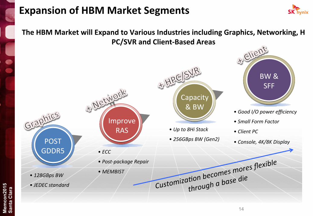
Expansion of HBM Market Segments
The HBM Market will Expand to Various Industries including Graphics, Networking, HPC/SVR and Client-‐Based Areas
BW & SFF
• ECC • Post-‐package Repair • MEMBIST
• Up to 8Hi Stack • 256GBps BW (Gen2)
Capacity & BW
Improve RAS
• 128GBps BW
• JEDEC standard
POST GDDR5
Customiza8on becomes mores flex
ible
through a base d
ie
• Good I/O power efficiency
• Small Form Factor
• Client PC
• Console, 4K/8K Display
15 Mem
con2
015
Sant
a C
lara
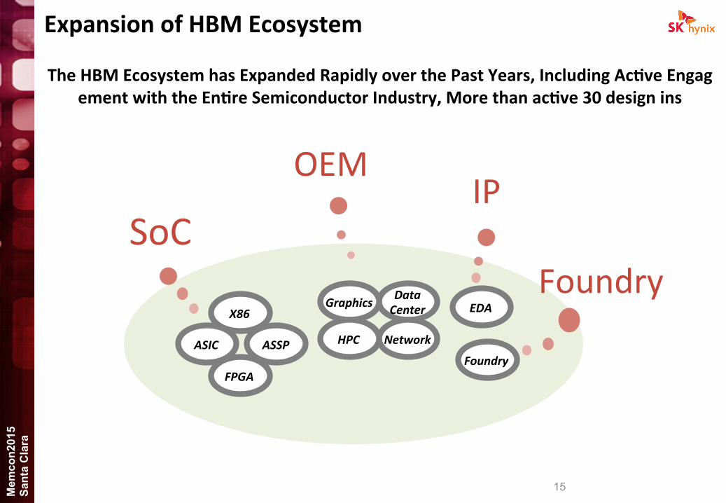
Expansion of HBM Ecosystem
The HBM Ecosystem has Expanded Rapidly over the Past Years, Including Ac@ve Engagement with the En@re Semiconductor Industry, More than ac@ve 30 design ins
SoC
OEM IP
X86
FPGA
ASIC ASSP
Data Center EDA
Foundry
Graphics
Network
Foundry HPC

16 Mem
con2
015
Sant
a C
lara
Readiness, Achievement, Posi@oning and Strategy of SKH

17 Mem
con2
015
Sant
a C
lara
HBM, What Exactly Is It?
Known Good Stacked Die(KGSD) Memory supported by System in Package
ADD/CMD,
DQ (RX/TX),
SIGNAL Connec?vity Test
TSV OVERLAP
DRAM POWER Supply
DA BALL
(Direct Access)
DFT
(TEST Logic)
PHY TSV Area DFT Area
Base Die
PHY TSV DA ball
DRAM Slice DRAM Slice DRAM Slice DRAM Slice
Interposer
SoC
PHY
Side
Molding
Side
Molding
HBM in SiP Fine Ball Grid Array (FBGA)
Known Good Stacked Die (KGSD)

18 Mem
con2
015
Sant
a C
lara
HBM Ecosystem & Supply Chain
SK hynix is in ac@ve coopera@on with all ecosystem partners
DRAM TSV chip
Logic Chip
Package Substrate
Logic
Substrate
Memory
Interposer
Substrate
Memory
Logic
2.5D
3D
Bonding Packaging
On Substrate Shipping
Foundry Memory (SKH) OSAT SoC Maker Set Make
r
For Sale Final Test (SiP test)
2.5D/3D IC
Interposer Wafer

19 Mem
con2
015
Sant
a C
lara
HBM Test Flow
KGSD
Wafer Wafer
KGSD Speed Test
PKG
Hot/Cold Test
Package Process
WFBI
TDBI
Hot/Cold Test
Repair
Hot/Cold Test
Stack Process (KGSD)
Logic Test
Hot/Cold Test & Repair
Repair
NEW
WFBI
Speed Test Speed Test
B/I Stress B/I Stress è Dynamic Stress (BISS)
KGSD(Known Good Stacked Die) : 3/5/9KGSD(1 Base Die + 2/4/8 Core Die)
Logic Test (IEEE1500)
DRAM Die
Base Die
Core Die
HBM in SiP Fine Ball Grid Array (FBGA)

20 Mem
con2
015
Sant
a C
lara
HBM KGSD Test
l DA pads for produc@vity l KGSD Test -‐ Covers TSV, DRAM cell, PHY, IEEE1500 -‐ Repairs TSV, DRAM cells
l TSV OS test and Repair
Test Area Func@on Detail item Coverage
PHY Func@on Test RD/WT,CL,BL 100%
Margin Test Speed, VDD, Setup/Hold Timing 100%
TSV Func@on Test RD/WT,CL,BL,TSV interface 100%
OS Check TSV Open/Short Check 100%
Logic Func@on Test IEEE1500, Func@on, BIST, Repair 100%
Margin Test VDD, Speed, Setup/Hold 100%
Core
Func@on Test RD/WT, Self Ref, Power Down 100%
Margin Test Speed, VDD, Async, Refresh 100%
Repair Cell Repair 100%
Test Coverage KGSD (Base/Core)
l uBump Test -‐ Screen leakage failure from uBump (DC) -‐ At-‐speed loopback test (AC)
l At-‐speed test on PHY, DRAM cells
HBM KGSD comprise of several func@ons, including:

21 Mem
con2
015
Sant
a C
lara
KGSD Reliability @ Proxy Package
Proxy Package Structure (6MCP)
SiP Structure
normal i/o linenormal i/o line
PHY
Interposer
STACKED DRAMSTACKED DRAM
STACKED DRAM
2CH / Die8CH / 4Hi Stack
1Gbit / CH128 IO/ CH
1K IO / Stack
STACKED DRAM
STACKED DRAMSTACKED DRAM
GPU
DRAM
DRAM
DRAM
PHYLogic die PHY
DRAM
TSV
Stacked DRAM
PHY
GPU
PHY
micro bump
PHY
micro bump
micro bump
Interposer
PKG Substrate PKG Ball Bump
PHY
PHY
PHY
PHY
STACKED DRAM
Logic die
Logic die
Logic die
Logic die
8CH / Stack1GByte / Stack1K IO / Stack
PHY
PHY
PHY
PHYTS
V
TSV
TSV
TSVStacked DRAM
TSV
TSVStacked DRAM
PHY DRAM DRAM DRAM
PHY Logic die PHY
D R A M TSV micro bump
PKG Substrate 6MCP Structure
Item Dura@on Result Remark
Pre condi@oning -‐ Pass 6MCP
EFR 48Hrs Pass 6MCP
HTOL 1008Hrs Pass 6MCP
Life Time Reliability Results (< 400ppm)
Wafer Burn In Probe Test Package Burn In Package Test
Wafer Burn In Probe Test Stacking BISS KGSD Test 6MCP (LAR)
General DRAM Flow
KGSD
• Life Time Reliability using Proxy package (6MCP) – KGSD samples from the HBM test flow passed LAR (Look Ahead Reliability)
– SKH is confident of the HBM Test base line & BISS DFT

22 Mem
con2
015
Sant
a C
lara
Built-‐in Reliability
HBM relieves customers of quality and reliability concerns through various RAS features as featured below
SoC
Interposer
Substrate
HBM 1 2 3 4 5
Cell Repair 1
Error Correc8ng Code Storage
2
PMBIST 4
BISS (Built-‐In Self Stress) 3
PHY DRAM DRAM DRAM
PHY Logic die PHY
D R A M TSV micro bump
PKG Substrate
Proxy Package 6
6
Microbump Repair 5

23 Mem
con2
015
Sant
a C
lara
HBM Test Features for 2.5D
HBM includes test/repair features for 2.5D accessible from host ASIC through IEEE1500 Available at 2.5D SiP aeer assembly
Items Features
IEEE 1500
BYPASS ALL-‐Channel Bypass
EXTEST RX/TX uBump boundary scan Rx/Tx test (Open/short)
MBIST Memory Built-‐In Self Test
SOFT_REPAIR So& repair of failing DRAM bit cells
HARD_REPAIR Hard repair of failing DRAM bit cells
DWORD MISR Read back signature in DWORD MISR
AWORD MISR Read back signature in AWORD MISR
SOFT/HARD_LANE_REPAIR Perform Lane remapping
DEVICE ID Read JTAG Device ID
TEMPERATURE Read 8-‐bits binary temperature code
MODE REGISTER DUMP Read/Write the DRAM’s Mode Register

24 Mem
con2
015
Sant
a C
lara
PPR(Post Package Repair) -‐ Soe & Hard Repair
normal i / o line
Controller
PHY
micro bump
PHY
Interposer
PKG Ball Bump
DRAM Core Slice3
DRAM Core Slice0
DRAM Core Slice1
DRAM Core Slice2
Base die PHY Channel0 Channel1
Channel6 Channel7
• DRAM Cell Test and Repair through IEEE1500 – Conducted a&er SiP Assembly
– 4-‐Row Rep / 2-‐Bank (Repair DRAM) (64 row per channel @ 8Hi)
• Procedure – Run MBIST: Pass/Fail, Report fail row addresses
– Run So& Repair: So& repair the fail row addresses by wri?ng register – Run Hard Repair: Hard repair the fail row addresses by cuxng e-‐Fuse

25 Mem
con2
015
Sant
a C
lara
Lane Repair
Simple DBI lost
Complex DBI maintained
• HBM supports interconnect lane remapping through IEEE1500 instruc@ons – Conducted a&er SiP Assembly
– Lane remapping is independent for each channel
• Procedure – Test lanes between HOST and HBM using EXTEST and MISR instruc?ons
– Run So&_Lane_Repair: Perform lane remapping by wri?ng register
– Run Hard_Lane_Repair: Perform lane remapping by cuxng eFuse

26 Mem
con2
015
Sant
a C
lara
HBM2 Line-‐up
8/4Gb-‐Based 9mKGSD(8Hi) 5mKGSD(4Hi) 3mKGSD(2Hi)
Density/Cube(GB) 8 4 2
IO(DQ) 1024 1024 1024
Speed/Pin(Gb/s) 1.0 1.6 2.0 1.0 1.6 2.0 1.0 1.6 2.0
Bandwidth(GB/s) 128 204 256 128 204 256 128 204 256
Usage HPC, Server, Network HPC, Server, Graphics, Network Graphics, Cache
Configura@on
SKH Provides a Wide HBM2 Line-‐up to Support Various Customers’ Needs

27 Mem
con2
015
Sant
a C
lara
SK hynix, TSV Development History
Continuous efforts in the development of TSV resulted in production of HBM1
SK hynix’s TSV Chronicle
(Source: SK Hynix)
2008 4Gb Flash
2010 4Gb DRAM DDP-‐WLP
2011 16Gb DRAM
9MCP
2011 16/32Gb DIMM
2011 4HI KGSD WIO
2013 4mKGSD HBM
Ø Volume Produc@on of HBM1
Ø HBM2 Universal Daisy Chain
Ø 9mKGSD HBM2 Development
2015 9mKGSD HBM2 D/C
SKH’s Plans for 2015
28 Mem
con2
015
Sant
a C
lara
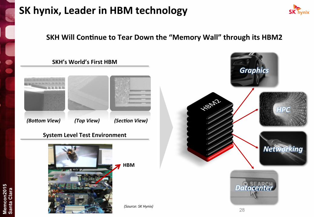
SK hynix, Leader in HBM technology
Graphics
HPC
Networking
Datacenter
(Source: SK Hynix)
SKH Will Con@nue to Tear Down the “Memory Wall” through its HBM2
(Bofom View) (Top View) (Sec4on View)
HBM
System Level Test Environment
SKH’s World’s First HBM

29 Mem
con2
015
Sant
a C
lara
Conclusion

30 Mem
con2
015
Sant
a C
lara
Conclusion ① HBM provides breakthrough memory solu@ons for power and form-‐factor constrained syste
ms through Higher BW, Lower latency, Lower power & Small FF
② Industry standard solu@on supports access to mul@ple supply sources
③ 2.5D Ecosystem requires close collabora@on among all stakeholders
④ SKH will maintain its lead in the TSV-‐Based technology market through produc@on of HBM2, overall accelera@ng innova@on through collabora@on
SiP Assembly & Test ASIC & Interposer Foundry
Business Ownership for SiP ASIC Design
Memory Vendor
COLLABORATION & PARTNERSHIP

31 Mem
con2
015
Sant
a C
lara
Thank You
If you have further ques@ons regarding SK Hynix and/or its memory products, please visit SK hynix website at www.skhynix.com