k2 a pe -k1 a2 c -k1 a1 d system information a2 ... - · pdf filebesi posses the required...
TRANSCRIPT

H
G
F
E
D
C
B
A
12
11
10
9
8
7
6
5
4
12
11
10
9
8
7
6
5
4
3
2
1
H
G
F
E
D
C
B
A
Maá
stab
Bear
b.
Gepr.Dat
um
Name
DIN 71
68
fein m
ittel g
rob
EDV N
r.
Posit
ion
Menge
Norm Nam
e
Datum
Žnde
rung
Zust
.
Blat
t
Bl.
Ober�
„che
PK10
0D011:1
28.0
1.94
SCHLO
MS
pneu
m.3-Weg
e Umste
llven
til
pneu
m. 3-w
ay ch
ange
over
valve
4-PKV
100-D
-0.1
W„rtsil„
Diesel
Oy
DN 65 , 8
0
BREM
ENBE
RG +
SIEB
ERT
4 - 8
19002010DINISO
Stck
Gegenstand
Pos.DIN
Modell-Nr.
Roh.-Maá
Fertigmaá
Werksto�
Zeichng.-Nr.
Lieferant
6-RV-L-0.1
GG
DN80
1
Geh„use
1
6-M3RV80-3.6
1.4301
DN80
4-661
2
Kronenkegel
1
6-M3RV-80-4.3
1.4301
DN80
4-661
3
oberer Ventilsitz
1
6-M3RV-1-VAU
St 35
DN 80
4
Unterer Ventilsitz
1
7-7
Graphit
7
7
Stopfbuchspackung
4
6-M3RV-L00-2.2
1.4305
í22h9 x 363
í22h9 x 368
8
Ventilspindel
1
6-M3RV-L00-11.1
C45
í56h9 x 109
í60 x 114
10
Stopfbuchs - Einsatz
1
6-MRV-00-6
CuSn10
í35,5 x 12
í36 x 17
11
Grundbuchse
1
6MRV-L00-6.1
Rg7
í42 x 19
í45 x 24
12
Stopfbuchsring
1
6-MRV-L00-15.1
Rg
í60 x 38
í60 x 43
13
Stopfbuchsmutter
1
6-MRV-00-12a So
CuZn35Ni
6kt 24 x 40
6kt 24 x 45
15
Kupplung
1
ARCA
16-NR-5-DN-80
GGG
Nr.5
16
Laterne
1
4-PKV100D-2.1a
CuSn8
í22h9 x 158
í22h9 x 163
17
Kolbenstange
1
4-HKV66-6a
CuSn8
í48 x 33,6
í50 x 39
19
F�hrungsbuchse
1
4-PKV100D-1.1
AlCuMgPb F38
4kt 120 x 120 x 56
4kt 120 x 120 x 61
20
Unterteil
1
4-PST4-7.1 So
POM
í100 x 30
í100 x 35
4-819
21
Kolben
1
4-PST 2T-9.1
AlCuMgPb F38
4kt 110 x 84
4kt 110 x 89
22
Zylinder
1
4-PKV100-D-819
St
25
Endschalterhalterung
1
6-MRV-L00-16.1
9S20K
í22 x 135
í22 x 140
26
Verdrehsicherung
1
4-819
St
™rtlichkeit
Fl.30 x 5
27
Verdrehsicherung
1
4-PKV100-D-819
St
Fl.120 x 30 x 5
28
Hebel
1
30-M-10-40-912
8.8
M10 x 40
912
30
Innensechskantschraube
4
31-M-12-35-912
8.8
M12 x 35
912
31
Innensechskantschraube
4
32-M-8-35-912
8.8
M8 x 35
912
32
Innensechskantschraube
4
33-M-4-25-912
8.8
M4 x 25
912
33
Innensechskantschraube
4
34-M-5-10-912
8.8
M5 x 10
912
34
Innensechskantschraube
2
36-M-16-1,5-934
8
M16 x 1,5
934
36
Sechskantmutte
r
3
37-M-12-934
8
M12
934
37
Sechskantmutte
r
1
40-OR-10-2-3770
NBR
OR10 x 2
3770
40
O-Ring
1
41-OR-30-3-3770
NBR
OR 30 x 3
3770
41
O-Ring
1
42-OR-102-2,5-3770
NBR
OR102 x 2,5
3770
42
O-Ring
1
43-S-8-22
NBR
S8-22
43
Nutring
2
Merkel
44-AIRZET 100
NBR
AIRZET 100
44
Kolbendichtung
1
spare part no.
Ersatzteil-Nr.
itemPos.
objectGegenstand
pcs.Stck
1
Geh„use
valve body
16-RV-L-0.1
1
Kronenkegel
cone
26-M
3RV80-3.6
1
oberer Ventilsitz
upper valve seat
36-M
3RV-80-4.3
1
Unterer Ventilsitz
lower valve seat
46-M
3RV-1-VAU
4
Stopfbuchspackung
stu�ng box packing
77-7
1
Ventilspindel
spindle
86-M
3RV-L00-2.2
1
Stopfbuchs - Einsatz
stu�ng box adaptor
106-M
3RV-L00-11.1
1
Grundbuchse
ground bush
116-M
RV-00-6
1
Stopfbuchsring
stu�ng box ring
126MRV-L00-6.1
1
Stopfbuchsmutter
cap nut
136-M
RV-L00-15.1
1
Kupplung
coupling
156-M
RV-00-12a So
1
Laterne
adaptor
1616-NR-5-DN-80
1
Kolbenstange
piston spindle
174-PKV100D-2.1a
1
F�hrungsbuchse
guiding bush
194-HKV66-6a
1
Unterteil
lower part
204-PKV100D-1.1
1
Kolben
piston
214-PST4-7.1 So
1
Zylinder
cylinder
224-PST 2T-9.1
1
Endschalterhalterung
fastening for limit s
witch
254-PKV100-D-819
1
Verdrehsicherung
safety lever of torsion
266-M
RV-L00-16.1
1
Verdrehsicherung
safety lever torsion
274-819
1
Hebel
lever
284-PKV100-D-819
4
Innensechskantschraube
socket head cap screw
3030-M
-10-40-912
4
Innensechskantschraube
socket head cap screw
3131-M
-12-35-912
4
Innensechskantschraube
socket head cap screw
3232-M
-8-35-912
4
Innensechskantschraube
socket head cap screw
3333-M
-4-25-912
2
Innensechskantschraube
socket head cap screw
3434-M
-5-10-912
3
Sechskantmutte
r
hexagon nut
3636-M
-16-1,5-934
1
Sechskantmutte
r
hexagon nut
3737-M
-12-934
1
O-Ring
o-ring
4040-OR-10-2-3770
1
O-Ring
o-ring
4141-OR-30-3-3770
1
O-Ring
o-ring
4242-OR-102-2,5-3770
2
Nutring
groove ring
4343-S-8-22
1
Kolbendichtung
piston joint ring
4444-AIRZET 100
2
Endschalter
Limit switch
5050-ZS-235-11-z
Telex:0245514
Fax.:0421/583621
Tel.:0421/57643-0
Postfach 66 03 04
Knechtsand 4
28259 Bremen,
BERG + SIEBERT
BREMENBERG + SIEBERT
Ersatzteilliste / li
st of spare parts
nach Zeichnungsnr. / acc. to
drawing no.:
Kom.Nr.:
com.no.:
28243 Bremen,
4-PKV100-D-0.1
4-819
Telex:0245514
Fax.:0421/583621
Tel.:0421/57643-0
Postfach 66 03 04
Knechtsand 4
28259 Bremen,
BERG + SIEBERT
BREMENBERG + SIEBERT
Ersatzteilliste / li
st of spare parts
nach Zeichnungsnr. / acc. to
drawing no.:
Kom.Nr.:
com.no.:
28243 Bremen,
4-PKV100-D-0.1
4-819
BREM
ENBE
RG +
SIEB
ERT Besteller:
Type:
Datum:
Name:
EDV Nr.:Blatt Nr.:
Blattzahl:
4-PKV100-D-0.1
pneum. 3way change over valve
pneum. 3 Wege Umstellventil
Schloms
02.02.94
PK100D011
2
DN80
BREM
ENBE
RG +
SIEB
ERT Besteller:
Type:
Datum:
Name:
EDV Nr.:Blatt Nr.:
Blattzahl:
4-PKV100-D-0.1
pneum. 3way change over valve
pneum. 3 Wege Umstellventil
Schloms
02.02.94
PK100D011
2
DN80
Schmersal
50-ZS-235-11-z
50
Endschalter
2
BREMENBERG + SIEBERT
BESI4-PKV100-D-0.1
over valve
pneum. 3-way change
Pneum. 3-Wege Umstellventil
n x Ø
d
L
�D�L
K n
x �d
DN
H2
L ØDDN
ØLK
H2H1
P1,P2=Druckanschluß R1/4"
pipe connections are included
(ERMETO-connection for p
ipe
outside dia 8mm)
BESI Lieferumfang (ERMETO-
Rohranschlüße gehören zum
Verschraubung für Rohr AD8mm)
P1
P2
130
445
145
185 29
0 4 x 1
8
4 x 1
823
016
550
125
65
430 13
0
160
310
200
8 x 1
8
80
495 15
5 H1
pressure connectio
n
M3~-M
U1V1
W1PE
-X1 1
L1
2
L2
3
L3
PE
PE
4
.
5
.
56
.
-K11.7
1412
11
7
.
8
.
-K21.8
1412
11
9
.
10
.
11
.
12
P1
2
-K1
A2
A1
13
14
P1
2
-K2
A2
A1
15
Junction Box ( BESI supply )
closed
open
Valve closed
Valve open
brow
n
blue
SR1
SH1
brow
n
blue
SR2
SH2
Valve(spring closing)
Proximity switchPressure switch
Proximity switchPressure switch
use Terminals 280-681280-687
closed
open
Indi
catio
n
Indi
catio
n
Con
tact
or
Con
tact
or
AC 3 x 115V / 60 Hz
Power supply Yard
DC 24 V
+ D
C 2
4 V
0 V
Valv
e
BrinkmannKnafla Boris Matesic
EHPP unit with volumetricindicator ( HSA ) and junction box
single acting function4-906-01 Rv.2-1.8.09
2
27.8.2009
EHPP1NB555
1
A
B
C
D
E
F
Status
1
Change
Date
2
Dat.Sig.
App.Name Standard
Origin
3
Constr. for
4
BESI Marine SystemsConstr. by
D-28259 Bremen
Knechtsand 4
5
6
Drawing. No.:
Comm. No.:
7
=+
Sheetof
8
A
B
C
D
E
F
1.4
14
121.4
11
1.5
14
121.5
11
BCS BESI Control System
Phone +49 (0) 421/57 64 3-0Fax +49 (0) 421/58 36 21e-mail [email protected] www.besi.de
BESI Marine SystemsGmbH & Co. KGKnechtsand 4 • 28259 BremenGermany
BESIMarine Systems GmbH & Co. KG
BESIMarine Systems GmbH & Co. KG F L O W M A N A G E M E N T
W W W . B E S I . D E
R E F E R E N C E S
Partnership inFlow ManagementWe associate with nearly all major shipyards worldwide. Until this moment, more than 4000 ships and offshore facilities have been equip-ped with BESI systems. To get a complete refe-rence list, please get in contact with us.
Open System Designed as an open system – products from other manufacturers such as loading compu-ters – can easily be connected to the BESI sy-stem via Ethernet switch.
If a communication partner cannot provide an Ethernet connection, or if the port is already in use, a serial RS485 interface is available.
Mimic diagram • Ballast system• Bilgesystem• Fueloilsystem• AntiHeelingSystem.• WaterIngresssystem• Remotecontrol
RC-Valves open/close operation• Ballastpumpson/offoperations• AntiHeelingSystem• RemotecontrolStart/StopBallastPump1&2• RemotecontrolStart/StopHFOPump1&2
Indications• RC-Valvespositionopen/close• BallastPumpsrunning• HFOPumpsrunning• TanklevelindicationsBallastWater, HFO,MDO,F-Water• Draft,fromsensors
Alarms• Bilgealarms• HFOtankalarmsHLA,andHHLA• MDOtankalarmHLA,andHHLA• Heelingangle• WaterIngressSystem
Typical designs and functions of panel menus are :
S Y S T E M I N F O R M AT I O N
BESI Control System
M3 ~
-M
U1 V1 W1 PE
-X1 1L1
2
L2
3
L3
PE
PE
4
.
5
.
5 6
.
-K11.7 1412
11
7
.
8
.
-K21.8 1412
11
9
.
10
.
11
.
12
P1
2
-K1
A2
A1
1314
P1
2
-K2
A2
A1
15
Junction Box ( BESI supply )
closed
open
Valve closedValve open
brow
n
blue
SR1SH1
brow
n
blue
SR2SH2
Valve(spring closing)
Proximity switch Pressure switch Proximity switch Pressure switch
use Terminals
280-681
280-687
closedopen
Indi
catio
n
Indi
catio
n
Con
tact
or
Con
tact
or
AC 3 x 115V / 60 HzPower supply Yard
DC 24 V
+ D
C 2
4 V
0 V Va
lve
Brinkmann
Knafla
Boris Matesic
EHPP unit with volumetric
indicator ( HSA ) and junction box
single acting function
4-906-01 Rv.2-1.8.09
2
27.8.2009
EHPP1
NB555
1
A
B
C
D
E
F
Status
1
ChangeDate
2
Dat.
Sig.
App.
Name StandardOrigin
3
Constr. for
4
BESI Marine Systems
Constr. by
D-28259 BremenKnechtsand 4
56
Drawing. No.:
Comm. No.:
7
=+
Sheet
of
8
A
B
C
D
E
F1.414
12 1.411
1.514
12 1.511
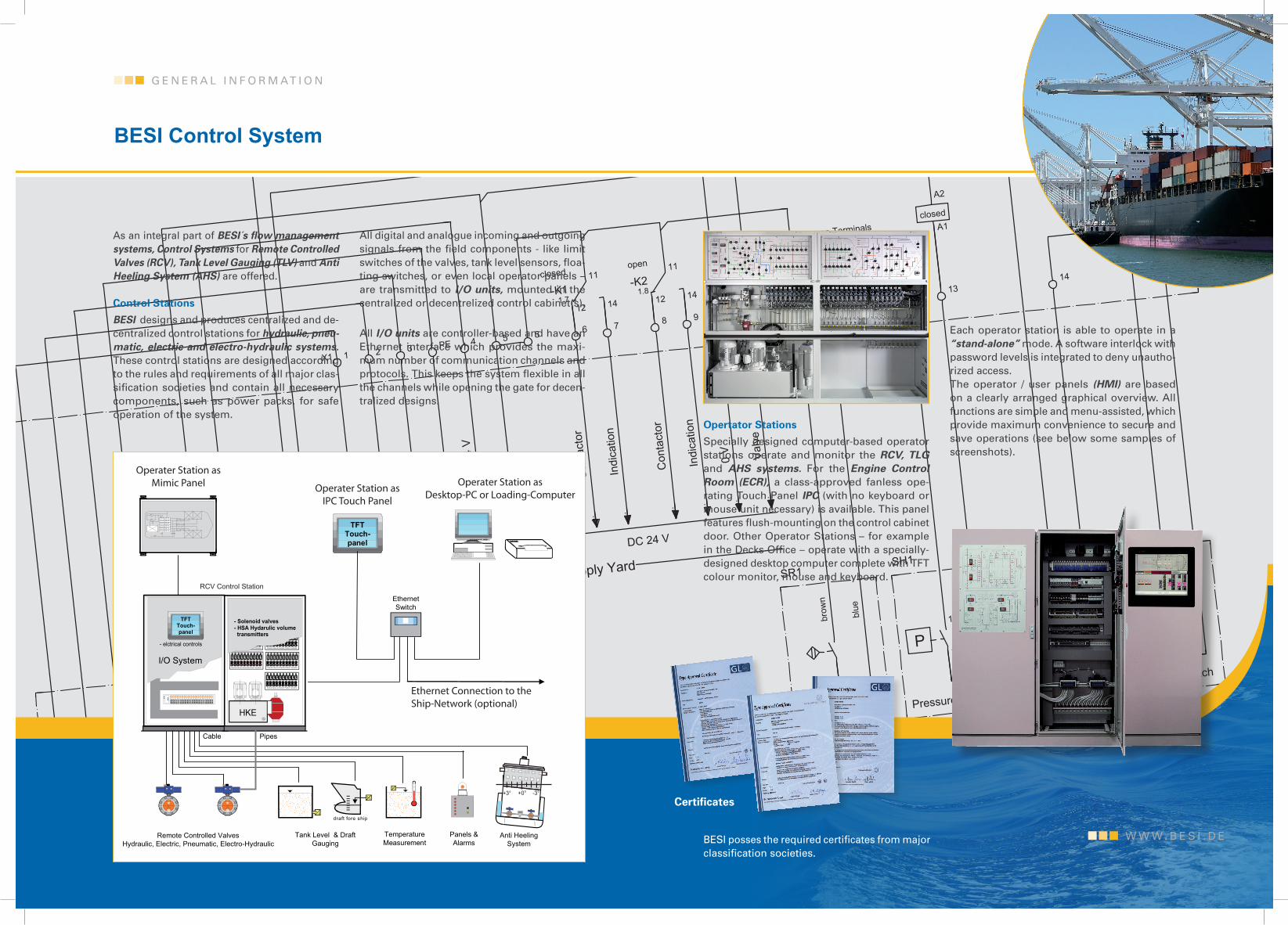
As an integral part of BESI´s flow management systems, Control Systems for Remote Controlled Valves (RCV), Tank Level Gauging (TLV) and Anti Heeling System (AHS) are offered.
Control Stations BESI designs and produces centralized and de-centralized control stations for hydraulic, pneu-matic, electric and electro-hydraulic systems. These control stations are designed according to the rules and requirements of all major clas-sification societies and contain all necessary components, such as power packs, for safe operation of the system.
All digital and analogue incoming and outgoing signals from the field components - like limit switches of the valves, tank level sensors, floa-ting switches, or even local operator panels – are transmitted to I/O units, mounted in the centralized or decentrelized control cabinet(s).
All I/O units are controller-based and have an Ethernet interface which provides the maxi-mum number of communication channels and protocols. This keeps the system flexible in all the channels while opening the gate for decen-tralized designs.
G E N E R A L I N F O R M AT I O N
BESI Control System
BESI posses the required certificates from major classification societies.
Certificates
W W W . B E S I . D E
Opertator Stations Specially designed computer-based operator stations operate and monitor the RCV, TLG and AHS systems. For the Engine Control Room (ECR), a class-approved fanless ope-rating Touch Panel IPC (with no keyboard or mouse unit necessary) is available. This panel features flush-mounting on the control cabinet door. Other Operator Stations – for example in the Decks Office – operate with a specially-designed desktop computer complete with TFT colour monitor, mouse and keyboard.
Each operator station is able to operate in a “stand-alone” mode. A software interlock with password levels is integrated to deny unautho-rized access.The operator / user panels (HMI) are based on a clearly arranged graphical overview. All functions are simple and menu-assisted, which provide maximum convenience to secure and save operations (see below some samples of screenshots).
Tank Level & Draft Gauging
Anti HeelingSystem
Panels &Alarms
Temperature Measurement
0 1 . 0 1
5 4 2 0
0 1 . 0 2
5 4 2 0
0 1 . 0 3
5 4 2 0
0 1 . 0 4
5 4 2 0
0 1 . 0 5
5 4 2 0
0 1 . 0 6
5 4 2 0
5 4 2 0
0 1 . 0 7
5 4 2 0
0 1 . 0 8
0 1 . 0 9
5 4 2 0
5 4 2 0
0 1 . 1 0
0 1 . 1 1
5 4 2 0
0 1 . 1 2
5 4 2 0
5 4 2 0
0 0 3 9
M G O
V O R R A T S
T A N K 8
M G O
V O R R A T S
T A N K 1 2
M G O
V O R R A T S
T A N K 1 3
V O R R A T S
M G O
T A N K 9
M G O V O R R A T S
T A N K 1 6
M G O V O R R A T S
T A N K 1 7
M G O
� B E R L A U F -
T A N K 2 3
B U N K E R S T A T I O N
F I L T E R S E P A R A T O R E N
P U M P E 1
M G O F Í R D E R -
P U M P E 2
M G O F Í R D E R -
Solenoid Valves & Volumetr ic Position Transmitter
Solenoid Valves & Volumetr ic Position Transmitter Solenoid Valves & Volumetr ic Position Transmitter
Solenoid Valves & Volumetr ic Position Transmitter
Solenoid Valves & Volumetr ic Position Transmitter
- elctrical controls
- Solenoid valves- HSA Hydarulic volume transmitters
HKE
15"Touch-panel
17"Touch-panel
15"Touch-panel
TFTTouch-panel
15"Touch-panel
17"Touch-panel
15"Touch-panel
TFTTouch-panel
EthernetSwitch
LI
draft fore ship
LI
LI
I/O System
Pipes Cable
+0° -3°+3°
Remote Controlled ValvesHydraulic, Electric, Pneumatic, Electro-Hydraulic
RCV Control Station
Operater Station asMimic Panel Operater Station as
IPC Touch Panel
Operater Station asDesktop-PC or Loading-Computer
Ethernet Connection to theShip-Network (optional)