energypedia.info · oven chamber sides, baking chamber supports, ... the purpose of this manual is...
TRANSCRIPT
�����! ����� #����� !�"�!��� ���"��
��� ����� ��!�� ���!!
����������� �������� ��� ���� ��� $�%� ������� ��%��� � ���% ��!!
�������� �� ��%�� ���"�� ��� ���� ��� $�%� ������� ��%��� � ���% ��!!
�� ���������� ������" � !�$� ���$� ����$� ���������
�
��� ����������������������� ������ ���� ��� ��������� ���
������������ ���� ��������� �����������

2
Table of Contents:
Title Page .................................................................................................................................................... 1 Introduction .................................................................................................................................................. 3
Before Construction .................................................................................................................................. 3 Equipment Needed ................................................................................................................................... 3 Drawings ................................................................................................................................................... 4
Construction ................................................................................................................................................ 5 1. Cut Sheet Drawings ............................................................................................................................ 5 2. Base.................................................................................................................................................... 5 3. Combustion Chamber ....................................................................................................................... 12 4. Taper ................................................................................................................................................ 20 5. Baking and Oven Chamber Flanges.................................................................................................. 28 6. Baking Chamber ............................................................................................................................... 36 7. Oven Chamber Sides, Baking Chamber Supports, and Baffle .............................................. 57 8. Fiberglass Barrier and Fiberglass .......................................................................................... 70 9. Manifold and Chimney ........................................................................................................... 84 10. Grate and Ash Remover ........................................................................................................ 88 11. Latches ................................................................................................................................ 100 12. (Optional) Additional Base ................................................................................................... 105 13. Sanding and Painting ......................................................................................................... 110 14. Pumice/Concrete ................................................................................................................. 111 15. Completed Oven .................................................................................................................. 113 16. Cleaning Procedure ............................................................................................................. 114 17. (Optional) Ceramic Grate..................................................................................................... 116 18. (Optional) Silicon Gasket ..................................................................................................... 118
3
Introduction
In the developing world, biomass is a major energy source. It is used in all levels of society from house hold use to the commercial sector. The large and growing need for biomass has created problems including deforestation and point of use health concerns. Deforestation has increased the scarcity of biomass and increased its price. Burning wood in traditional methods is ineffective in both heating and combustion. Incomplete combustion leads to health concerns because of the chemicals and particles liberated during the reaction. The method for solving these problems is to create more efficient technology.
This oven is a response to these issues in the area of wood burning ovens. It burns more efficiently and therefore cleaner. Its efficiency reduces the amount of wood used and resulting in lower operating cost. The oven is intended of bakery scale production with two racks measuring 115x69cm.
The purpose of this manual is to guide the producer through the construction process. The manual assumes that an experienced craftsman will be constructing the oven. It is a flexible tool to build bakery scale wood burning rocket bread ovens. Before Construction Throughout the manual two different types of welds are referenced, a hermetic seal weld and a spot weld. The hermetic seal weld is a weld that is air tight. These welds are critical in certain areas so that during use the flue gas does enter into the baking chamber and other areas. Thermal expansion is an issue with the oven, which is why in other areas spot welds are used. Equipment Needed When constructing the oven safety is to be the first priority. It is critical that the following tools and materials are used so as to prevent injury. See the tables below for the equipment needed.
Personal Protection Equipment (PPE) Item Purpose
Safety Glasses Protect eyes Welding Mask Protect eyes and face Gloves Protect hands Boots Protect feet Overalls Protect Clothing First Aid Kit Effective response to
injuries Fire Extinguisher Effective response to
fires
Metal Working Equipment Item Purpose
Arc Welding Set Combining metal pieces Electrodes Welding Hammer Shaping metal Anvil Shaping metal Measuring Tape Measuring Square Measuring right angles Straight edge/ Chalk Marking lines to cut Metal Cutter Cut sheet metal Hand-held Grinder Cut and smooth pieces

4
Table Grinder Cut metal bar and pipe Drill and bits Drill holes in sheet metal
Other Equipment
Item Purpose Shears Cutting fiber glass Hack Saw Cutting ceramic bricks Shovel Moving pumice
Drawings
Figure 1: 2D AutoCAD Drawings of Completed Oven – Side View (left) Front view with dimensions (right)

5
Construction 1. Cut Sheet Drawings The following images detail metal cuts for 2x1m sheet metal
See Attached Files 2. Base
Pipe Amount Specifications Dimensions
4 3x3cm square pipe 63cm 2 2x2cm square pipe 73cm 2 2x2cm square pipe 120.5cm
Bar
Amount Specifications Dimensions 2 3x3x0.3cm angle bar 73cm
Sheet Metal
Amount Specifications Dimensions 4 0.15cm thick 3x3cm
2.1. Weld a 3x3cm 63cm long square pipe to each end of the 2x2cm 73cm long piece of square
pipe. This will result in a U-shape as in the images shown below. Be sure to make the 2x2cm square pipe flush with the inside edges of the 3x3cm square pipe (See Figure 3).
Figure 2: Dimensions for U-Shape

6
Figure 3: 3D figure of U-shape (left) and 3D image of 2x2cm square pipe flush with 3x3cm square pipe (right)
Picture 1: Image of U-shape (left) and image of 2x2cm square pipe flush with 3x3cm square pipe (right)
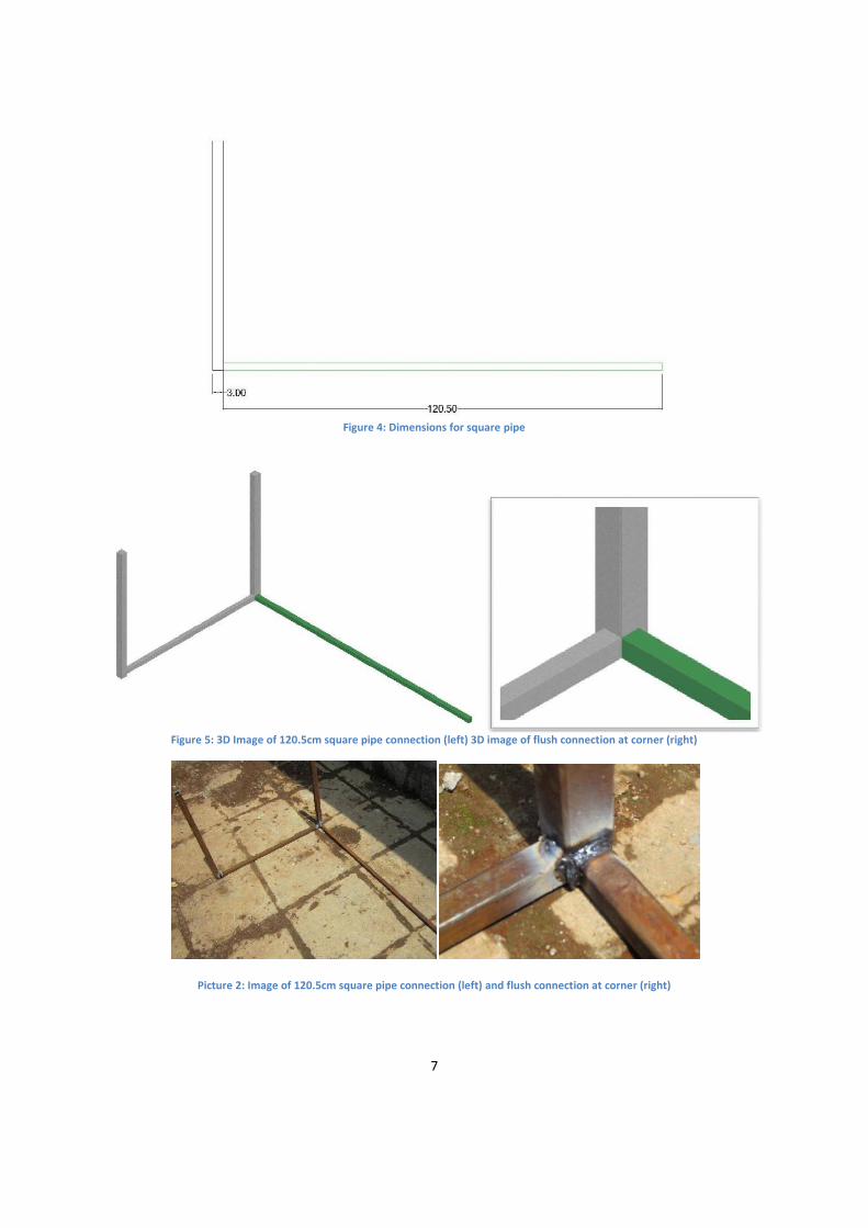
2.2. Repeat step 1.1 to create a second U-shaped piece. 2.3. Weld a 2x2cm 120.5cm long piece of square pipe to a corner of the U-shape as seen in the
images below. Make sure the piece is flush with the inside edge (See Figure 5).
7
Figure 4: Dimensions for square pipe
Figure 5: 3D Image of 120.5cm square pipe connection (left) 3D image of flush connection at corner (right)
Picture 2: Image of 120.5cm square pipe connection (left) and flush connection at corner (right)

8
2.4. Weld another 2x2cm 120.5cm long piece of square pipe to the other corner of the U-shape as seen in the image below. Again making sure the piece is flush with the inside edge (See Figure 5).
Figure 6: 3D Image of second 120.5cm square pipe piece attached
Picture 3: Image of second 120.5cm square pipe piece attached
2.5. Weld the other U-shaped piece to the open ends of the120.5cm long pieces of 2x2cm square pipe. Once again, make sure that the inside edges are flush with one another (See Figure 5).

9
Figure 7: 2D Image with addition of second U-shaped piece
Figure 8: 3D Image with second U-shaped piece attached
10
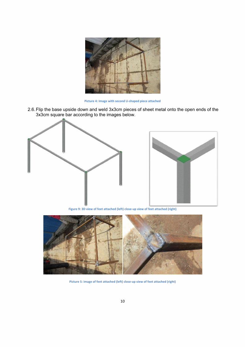
Picture 4: Image with second U-shaped piece attached
2.6. Flip the base upside down and weld 3x3cm pieces of sheet metal onto the open ends of the 3x3cm square bar according to the images below.
Figure 9: 3D view of feet attached (left) close-up view of feet attached (right)
Picture 5: image of feet attached (left) close-up view of feet attached (right)
11
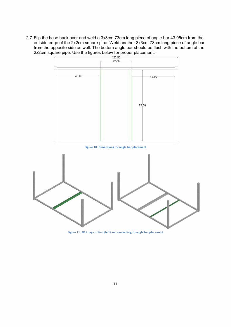
2.7. Flip the base back over and weld a 3x3cm 73cm long piece of angle bar 43.95cm from the outside edge of the 2x2cm square pipe. Weld another 3x3cm 73cm long piece of angle bar from the opposite side as well. The bottom angle bar should be flush with the bottom of the 2x2cm square pipe. Use the figures below for proper placement.
Figure 10: Dimensions for angle bar placement
Figure 11: 3D Image of first (left) and second (right) angle bar placement

12
Picture 6: Image of first (left) and second (right) angle bar placement
2.8. (Optional) For an additional base to increase the height to the oven see step 11.
3. Combustion Chamber
3.1. Metal Cladding for combustion Chamber
Sheet Metal Amount Specifications Dimensions
2 .15cm thick 55.9x31.7cm 1 .15cm thick 144x32cm
The metal box for the combustion chamber is prepared from three separate pieces of 1.5mm mild steel sheets. The two side walls and bottom are made from a single section of sheet metal. Two separate pieces of sheet metal are used to make the front and back sections. The figure below shows the three separate pieces.
Figure 12: Pieces of sheet metal for combustion chamber cladding
3.1.1. Produce the bottom and sides of the metal combustion chamber by first chalking the folding lines on piece 2 of the combustion chamber.
13
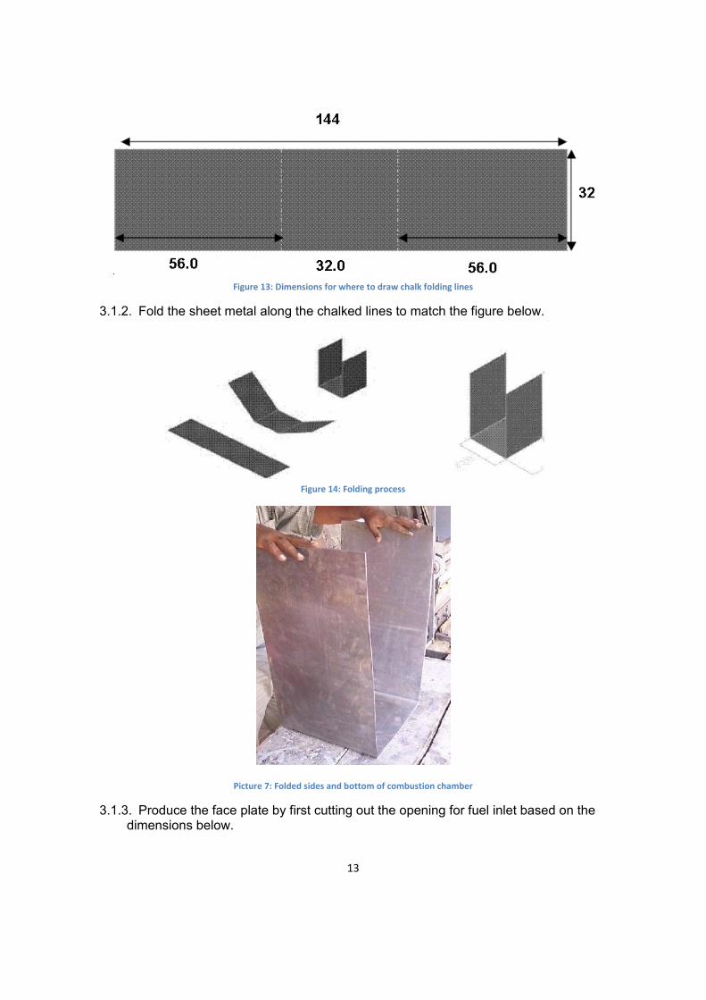
Figure 13: Dimensions for where to draw chalk folding lines
3.1.2. Fold the sheet metal along the chalked lines to match the figure below.
Figure 14: Folding process
Picture 7: Folded sides and bottom of combustion chamber
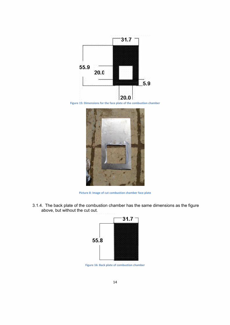
3.1.3. Produce the face plate by first cutting out the opening for fuel inlet based on the dimensions below.
14
Figure 15: Dimensions for the face plate of the combustion chamber
Picture 8: Image of cut combustion chamber face plate
3.1.4. The back plate of the combustion chamber has the same dimensions as the figure
above, but without the cut out.
Figure 16: Back plate of combustion chamber
15
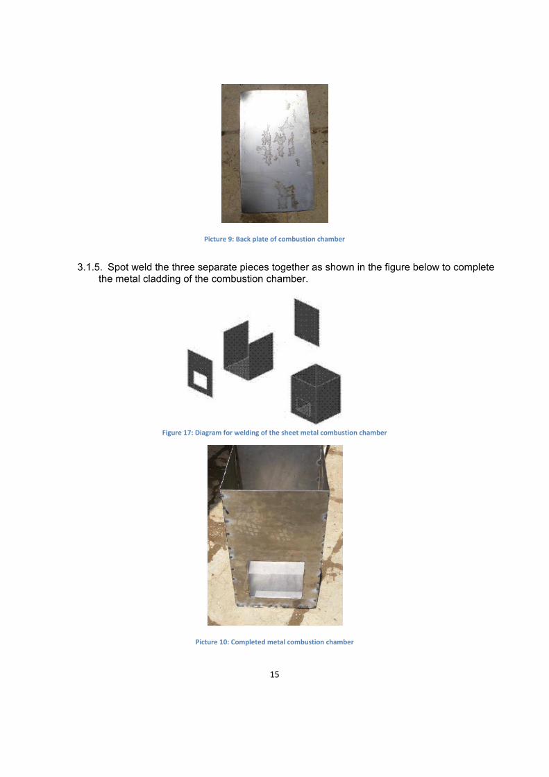
Picture 9: Back plate of combustion chamber
3.1.5. Spot weld the three separate pieces together as shown in the figure below to complete the metal cladding of the combustion chamber.
Figure 17: Diagram for welding of the sheet metal combustion chamber
Picture 10: Completed metal combustion chamber

16
3.1.6. Spot weld the metal combustion chamber to the base according to the dimensions and images below.
Figure 18: Dimensions for placement of combustion chamber
Figure 19: 3D image for placement of combustion chamber

17
Picture 11: Image of combustion chamber added to base
3.2. Addition of Pumice and Ceramic Tiles
The following material is needed for the addition of the pumice and tiles:
Pumice and Ceramic Tiles Amount Specifications Dimensions
1 3cm thick 20x26cm 1 3cm thick 26x4cm 2 3cm thick 23x29cm 5 3cm thick 30x26cm
Pumice
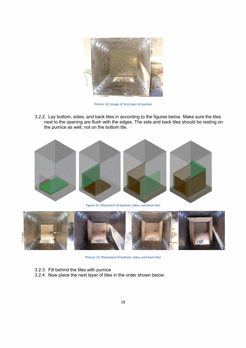
3.2.1. Add a 3cm layer of pumice to the bottom of the combustion chamber.
Figure 20: 3D image of 3cm layer of pumice
18
Picture 12: Image of 3cm layer of pumice
3.2.2. Lay bottom, sides, and back tiles in according to the figures below. Make sure the tiles next to the opening are flush with the edges. The side and back tiles should be resting on the pumice as well, not on the bottom tile.
Figure 21: Placement of bottom, sides, and back tiles
Picture 13: Placement of bottom, sides, and back tiles
3.2.3. Fill behind the tiles with pumice 3.2.4. Now place the next layer of tiles in the order shown below.

19
Figure 22: Placement of second layer of ceramic tiles
Picture 14: Placement of second layer of ceramic tiles
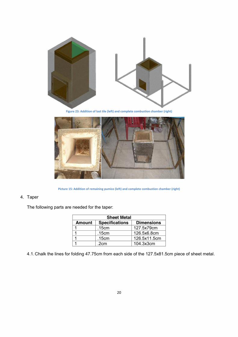
3.2.5. After the last tile is placed in the chamber, mark where it hits the top and then cut off the
excess. Then place back in the chamber and back fill the tiles with pumice. Notice the difference between the last image in Figure 24 and the first image in Figure 25.
20
Figure 23: Addition of last tile (left) and complete combustion chamber (right)
Picture 15: Addition of remaining pumice (left) and complete combustion chamber (right)
4. Taper
The following parts are needed for the taper:
Sheet Metal Amount Specifications Dimensions 1 .15cm 127.5x79cm 1 .15cm 126.5x6.8cm 1 .15cm 126.5x11.5cm 1 .2cm 104.3x3cm
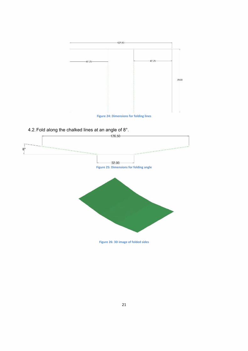
4.1. Chalk the lines for folding 47.75cm from each side of the 127.5x81.5cm piece of sheet metal.
21
Figure 24: Dimensions for folding lines
4.2. Fold along the chalked lines at an angle of 8°.
Figure 25: Dimensions for folding angle
Figure 26: 3D image of folded sides

22
Picture 16: Image of folded sides
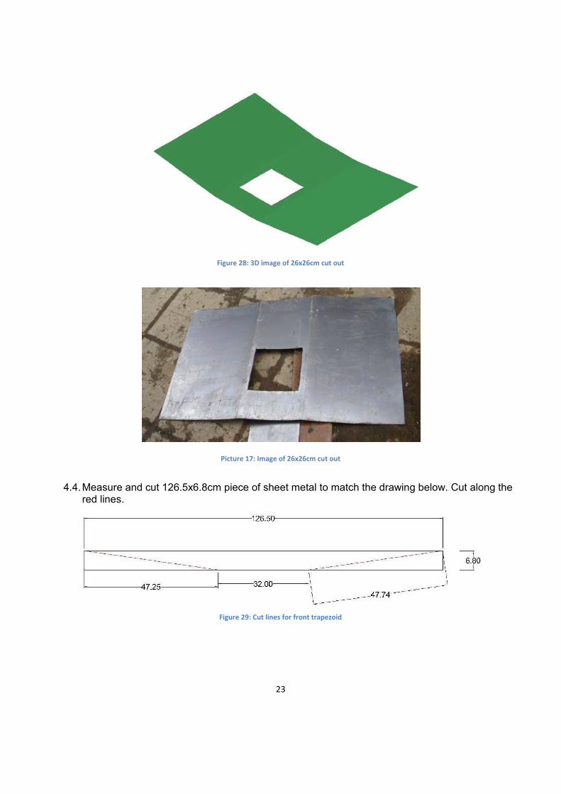
4.3. Cut out a 26x26cm square from the taper.
Figure 27: Dimensions for square cut-out
23
Figure 28: 3D image of 26x26cm cut out
Picture 17: Image of 26x26cm cut out
4.4. Measure and cut 126.5x6.8cm piece of sheet metal to match the drawing below. Cut along the red lines.
Figure 29: Cut lines for front trapezoid

24
Picture 18: Cut out front trapezoid
4.5. Weld front trapezoid, cut in the previous step, to the taper.
Figure 30: 3D image of front trapezoid attached
Picture 19: Image of front trapezoid attached
4.6. Measure and cut the 126.5x11.5cm piece of sheet metal to match the drawing below. Cut along the red lines.

25
Figure 31: Cut lines for back trapezoid
Picture 20: Cut out back trapezoid
4.7. Spot weld the back trapezoid, cut in the previous step, to the taper.
Figure 32: 3D image of back trapezoid attached

26
Picture 21: Image of back trapezoid attached
4.8. First, set the taper on top of the combustion chamber and legs. Next grind the legs of the base to accommodate the angle of the taper. After the legs have been ground, spot weld the taper to the top of the combustion chamber and then to the legs.
Figure 33: 3D image of taper added to combustion chamber and base

27
Picture 22: Image of taper added to combustion chamber and base
4.9. Chalk the folding lines on the piece of sheet metal that is to be the lip above the combustion
chamber.
Figure 34: Dimensions for folding lines on combustion chamber lip
4.10. Fold along lines to form square lip and then spot weld to the top opening of the combustion chamber.
Figure 35: 3D image of lip attached
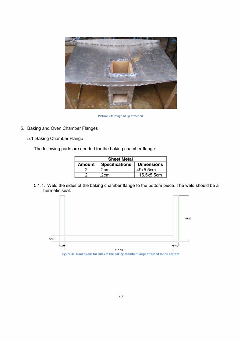
28
Picture 23: Image of lip attached
5. Baking and Oven Chamber Flanges
5.1. Baking Chamber Flange
The following parts are needed for the baking chamber flange:
Sheet Metal Amount Specifications Dimensions
2 .2cm 49x5.5cm 2 .2cm 115.5x5.5cm
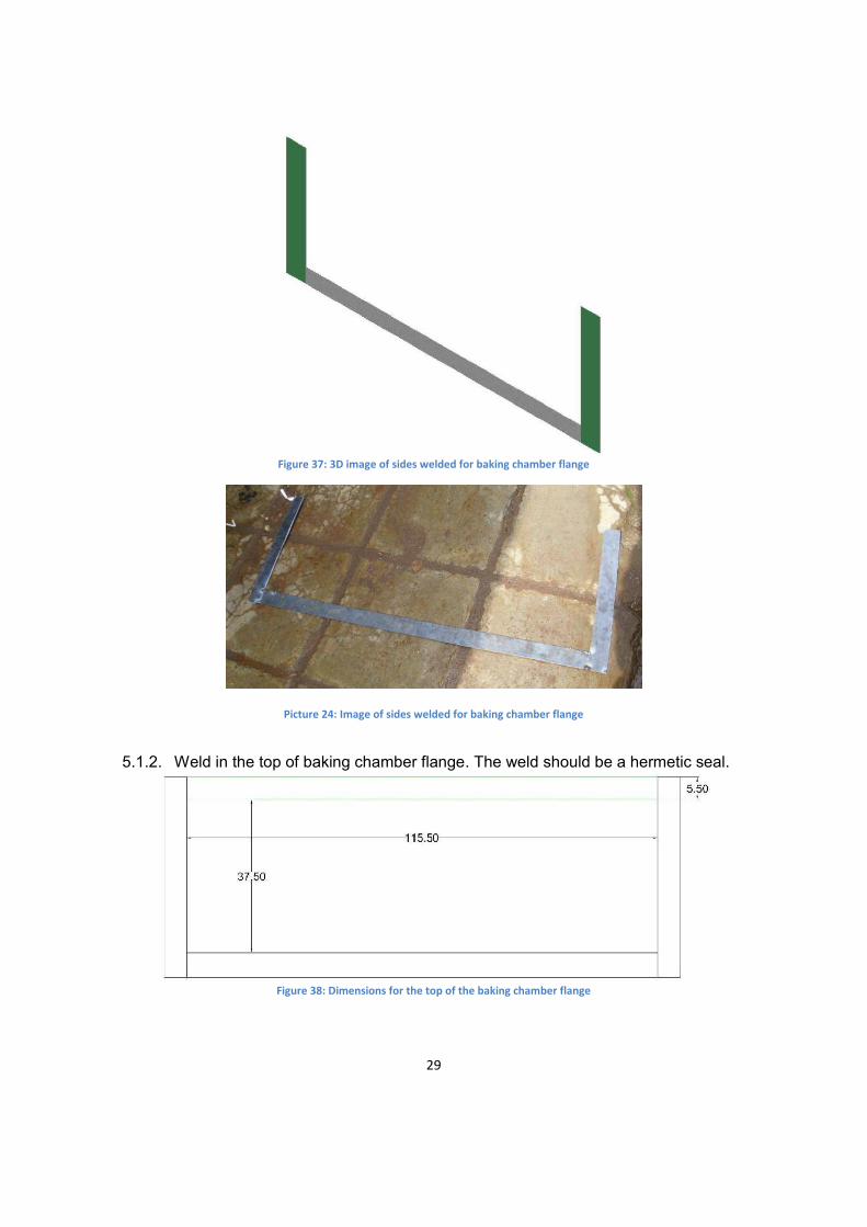
5.1.1. Weld the sides of the baking chamber flange to the bottom piece. The weld should be a
hermetic seal.
Figure 36: Dimensions for sides of the baking chamber flange attached to the bottom
29
Figure 37: 3D image of sides welded for baking chamber flange
Picture 24: Image of sides welded for baking chamber flange
5.1.2. Weld in the top of baking chamber flange. The weld should be a hermetic seal.
Figure 38: Dimensions for the top of the baking chamber flange

30
Figure 39: 3D image of the top of the baking chamber flange attached
Picture 25: Image of the top of the baking chamber flange attached
5.2. Oven Chamber Flange
The following parts are needed for the oven chamber flange:
Sheet Metal Amount Specifications Dimensions
2 .2cm thick 44x3cm 1 .2cm thick 126.5x6.7cm 1 .2cm thick 120.5x3cm
5.2.1. Spot weld the sides of the oven chamber flange

31
Figure 40: Dimensions for the sides of the oven chamber flange
Figure 41: 3D image of the sides of the oven chamber flange attached
Picture 26: image of the sides of the oven chamber flange attached
32
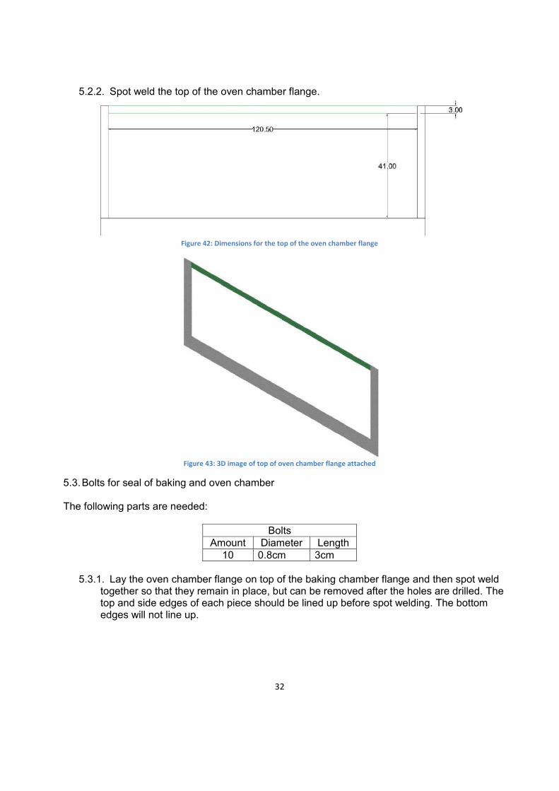
5.2.2. Spot weld the top of the oven chamber flange.
Figure 42: Dimensions for the top of the oven chamber flange
Figure 43: 3D image of top of oven chamber flange attached
5.3. Bolts for seal of baking and oven chamber
The following parts are needed:
Bolts Amount Diameter Length
10 0.8cm 3cm
5.3.1. Lay the oven chamber flange on top of the baking chamber flange and then spot weld together so that they remain in place, but can be removed after the holes are drilled. The top and side edges of each piece should be lined up before spot welding. The bottom edges will not line up.

33
Figure 44: Oven chamber flange (black) on top of baking chamber flange (green)
Figure 45: Oven chamber flange (gray) on top of baking chamber flange (green)
Picture 27: Oven chamber flange on top of baking chamber flange
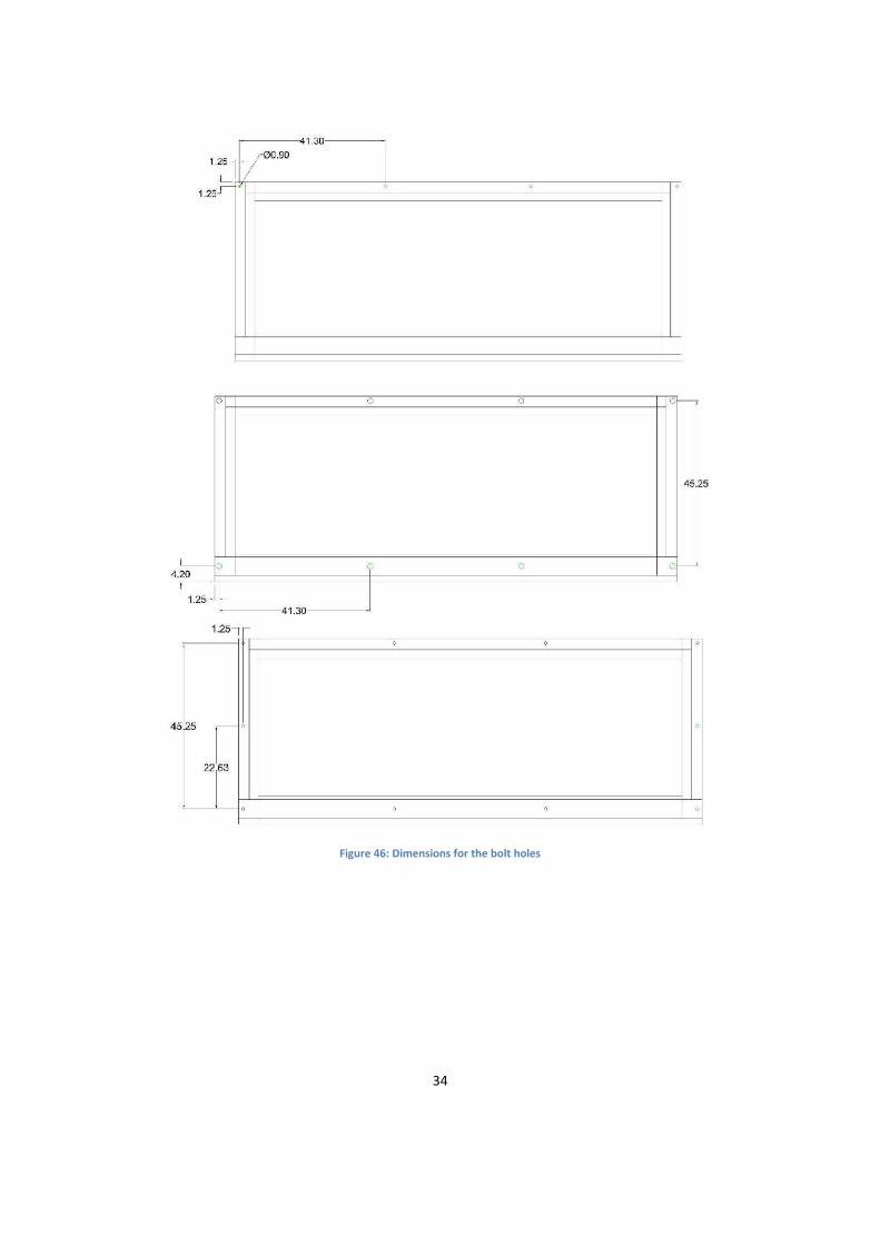
5.3.2. Drill 0.9cm holes along the top, sides, and bottom according to the dimensions below. Dimensions are measured from the center of the bolt holes.
34
Figure 46: Dimensions for the bolt holes

35
Picture 28: Top and bottom (left) and side (right) bolt holes
5.3.3. Once holes are drilled separate the two flanges. Expand the existing holes of the baking
chamber flange to 1.5cm in diameter with drill.
Figure 47: Dimensions for baking chamber flange bolt holes
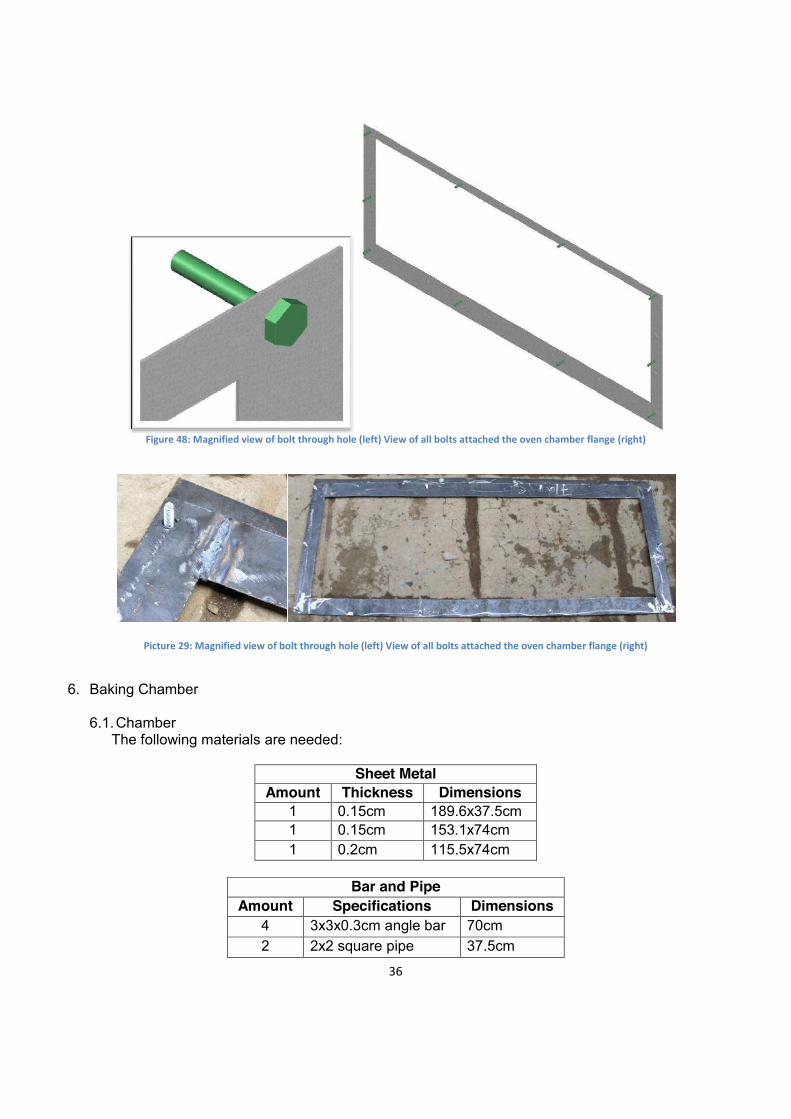
5.3.4. On the oven chamber flange, weld the 0.8cm diameter, 3cm bolts through the holes.
36
Figure 48: Magnified view of bolt through hole (left) View of all bolts attached the oven chamber flange (right)
Picture 29: Magnified view of bolt through hole (left) View of all bolts attached the oven chamber flange (right)
6. Baking Chamber
6.1. Chamber The following materials are needed:
Sheet Metal
Amount Thickness Dimensions 1 0.15cm 189.6x37.5cm 1 0.15cm 153.1x74cm 1 0.2cm 115.5x74cm
Bar and Pipe
Amount Specifications Dimensions 4 3x3x0.3cm angle bar 70cm 2 2x2 square pipe 37.5cm
37
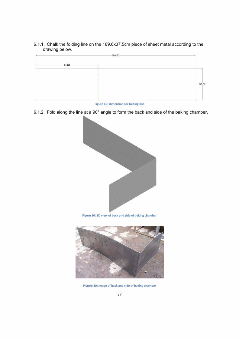
6.1.1. Chalk the folding line on the 189.6x37.5cm piece of sheet metal according to the
drawing below.
Figure 49: Dimension for folding line
6.1.2. Fold along the line at a 90° angle to form the back and side of the baking chamber.
Figure 50: 3D view of back and side of baking chamber
Picture 30: Image of back and side of baking chamber
38
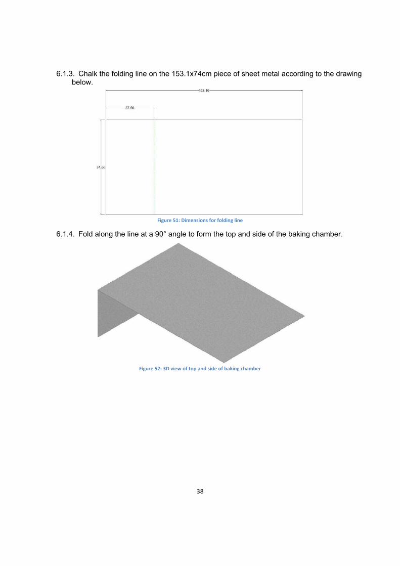
6.1.3. Chalk the folding line on the 153.1x74cm piece of sheet metal according to the drawing
below.
Figure 51: Dimensions for folding line
6.1.4. Fold along the line at a 90° angle to form the top and side of the baking chamber.
Figure 52: 3D view of top and side of baking chamber

39
Picture 31: Image of top and side of baking chamber
6.1.5. Weld two pieces of 70cm 3x3cm angle bar onto the side of the baking chamber
according to the dimensions and images below.
Figure 53: Dimensions for placement of angle bar rack supports on side of baking chamber
Figure 54: 3D image of angle bar rack supports attached

40
Picture 32: Image of angle bar rack supports attached
6.1.6. Weld the other two 70cm 3x3cm angle bar supports on the opposite side of the baking chamber according to the dimensions and images below.
Figure 55: Dimensions for placement of angle bar rack supports on side of baking chamber
Figure 56: 3D image of angle bar rack supports attached
41
Picture 33: Image of angle bar rack supports attached
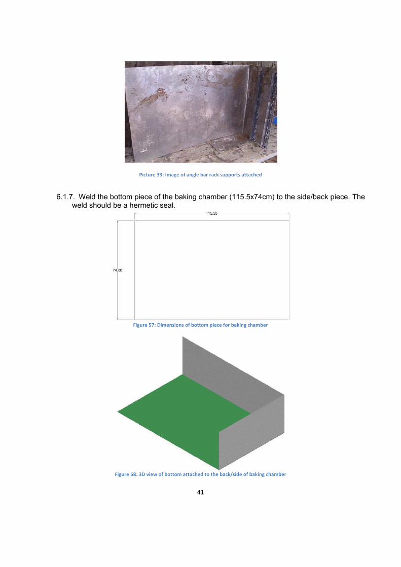
6.1.7. Weld the bottom piece of the baking chamber (115.5x74cm) to the side/back piece. The
weld should be a hermetic seal.
Figure 57: Dimensions of bottom piece for baking chamber
Figure 58: 3D view of bottom attached to the back/side of baking chamber
42
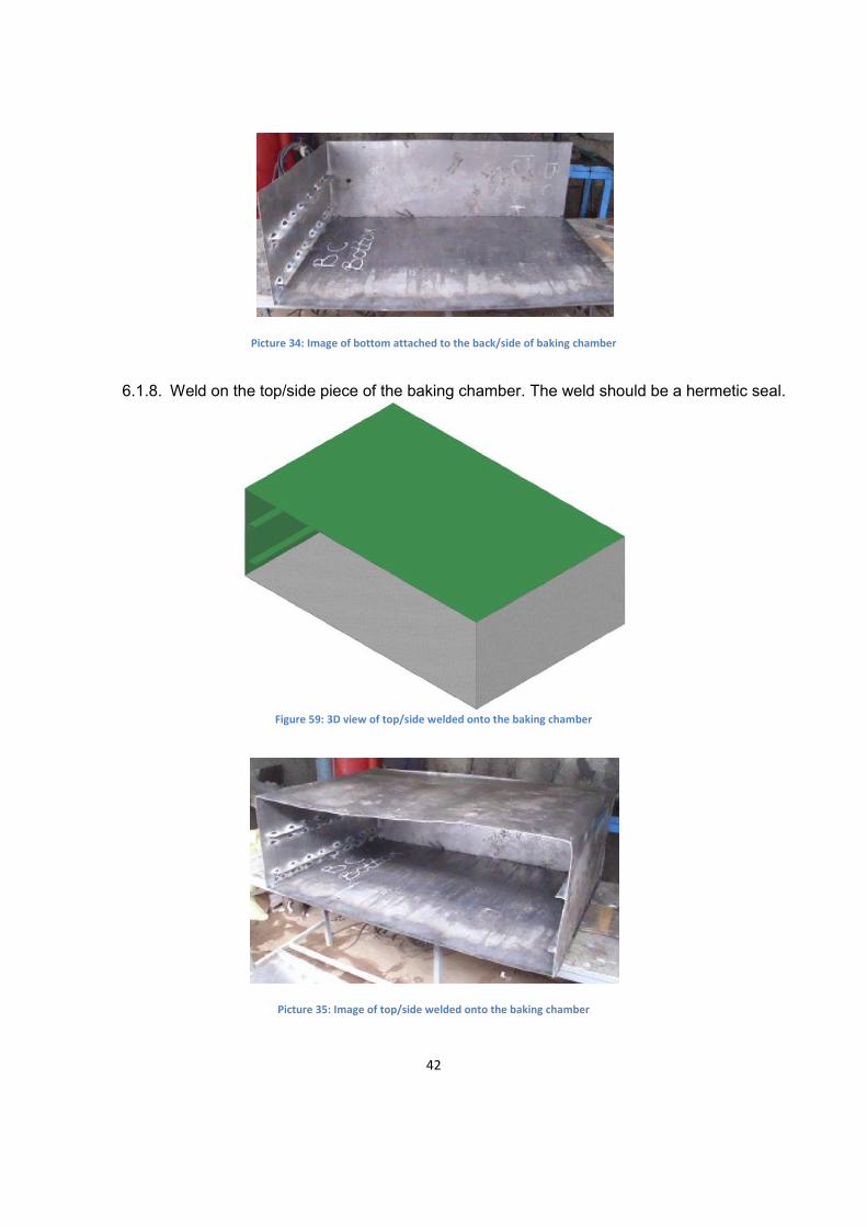
Picture 34: Image of bottom attached to the back/side of baking chamber
6.1.8. Weld on the top/side piece of the baking chamber. The weld should be a hermetic seal.
Figure 59: 3D view of top/side welded onto the baking chamber
Picture 35: Image of top/side welded onto the baking chamber
43
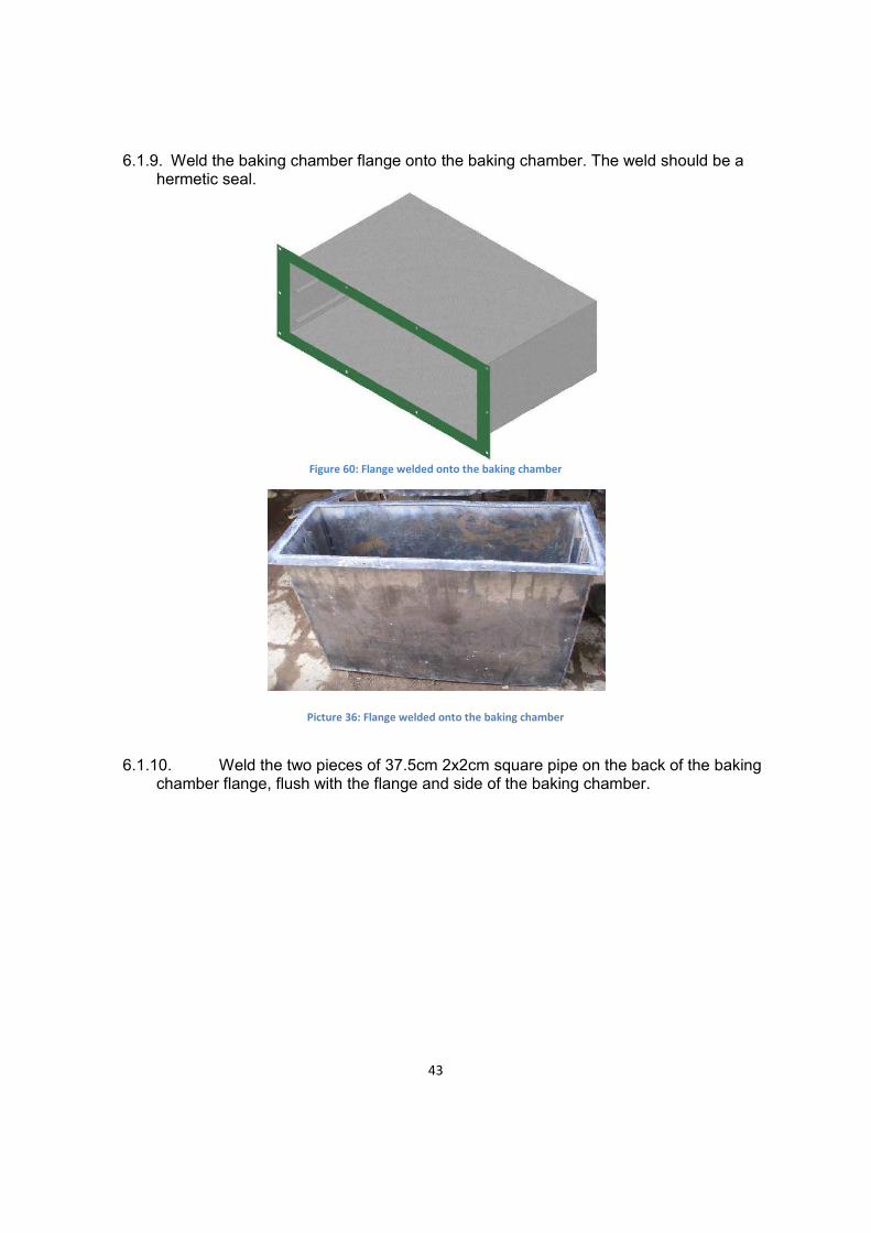
6.1.9. Weld the baking chamber flange onto the baking chamber. The weld should be a
hermetic seal.
Figure 60: Flange welded onto the baking chamber
Picture 36: Flange welded onto the baking chamber
6.1.10. Weld the two pieces of 37.5cm 2x2cm square pipe on the back of the baking
chamber flange, flush with the flange and side of the baking chamber.

44
Figure 61: Square pipe attached to the back of the baking chamber flange, flush with top and bottom
Picture 37: Square pipe attached to the back of the baking chamber flange (left), flush with top and bottom (right)
6.2. Racks
The following pieces are need for the racks:
Round Bar Amount Specifications Dimensions
22 0.6cm diameter 115cm 8 0.6cm diameter 70cm
6.2.1. Create a rectangle by welding according to the drawings and images below. Make sure
the 115cm round bar is welded on top of the 70cm round bar (see Figure 63).

45
Figure 62: Dimensions for rectangle
Figure 63: 115cm round bar (grey) on top of 70cm round bar (green) (left) 3D view of rectangle (right)
6.2.2. Weld two more 70cm pieces of round bar 40cm from each side of the rectangle. Again making sure you weld them under the 115cm piece of round bar.

46
Figure 64: Dimensions for supports
Figure 65: View of 115cm bar (gray) on top of 70cm bar (green) (left) 3D view of supports attached (right)
6.2.3. Weld nine 115cm pieces of round bar, according to the drawings and images below. These pieces are on top of the 70cm pieces of round bar. Dimensions are measured from edges of round bar.

47
Figure 66: Dimensions for 9 pieces of 115cm round bar
Figure 67: 3D view of completed rack
48
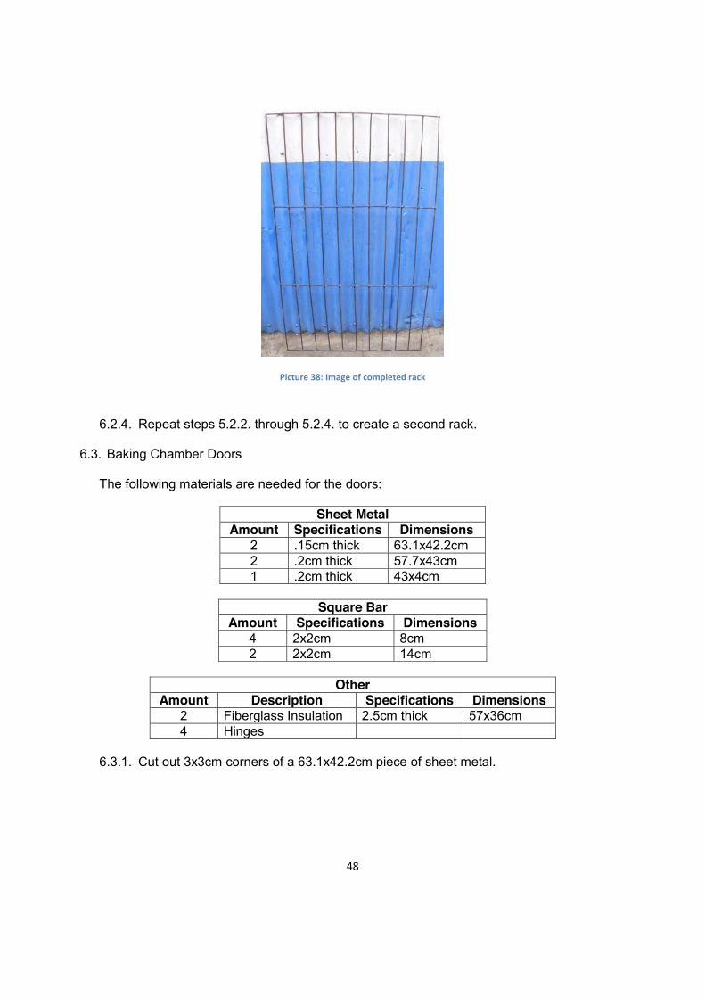
Picture 38: Image of completed rack
6.2.4. Repeat steps 5.2.2. through 5.2.4. to create a second rack.
6.3. Baking Chamber Doors
The following materials are needed for the doors:
Sheet Metal Amount Specifications Dimensions
2 .15cm thick 63.1x42.2cm 2 .2cm thick 57.7x43cm 1 .2cm thick 43x4cm
Square Bar
Amount Specifications Dimensions 4 2x2cm 8cm 2 2x2cm 14cm
Other
Amount Description Specifications Dimensions 2 Fiberglass Insulation 2.5cm thick 57x36cm 4 Hinges
6.3.1. Cut out 3x3cm corners of a 63.1x42.2cm piece of sheet metal.

49
Figure 68: Dimensions for cut outs (left) 3D image of corners cut out (right)
Picture 39: Image of corners cut out
6.3.2. Fold down along the lines to create sides and weld the edges together to create an
open face box.
50
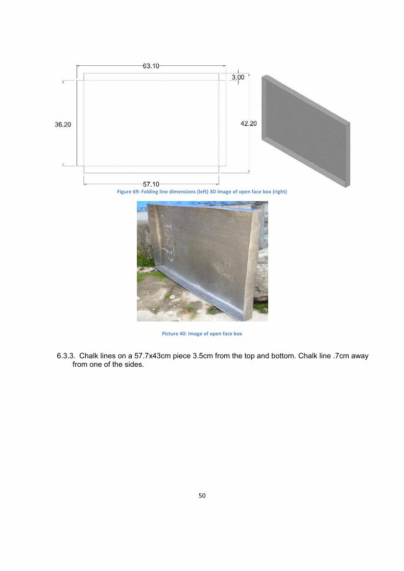
Figure 69: Folding line dimensions (left) 3D image of open face box (right)
Picture 40: Image of open face box
6.3.3. Chalk lines on a 57.7x43cm piece 3.5cm from the top and bottom. Chalk line .7cm away
from one of the sides.

51
Figure 70: Chalk line dimensions
6.3.4. Insert 2.5cm thick fiber glass insulation into the open face box.
Figure 71: 3D image of insulation added

52
Picture 41: Image of insulation added
6.3.5. Weld open face box with insulation to where the chalked lines are on 57.7x43cm piece
of sheet metal.
Figure 72: 3D image of open face box attached to the 57.7x43cm piece (green)
Picture 42: Image of open face box attached to the 57.7x45cm piece

53
6.3.6. Repeat steps 5.3.1 through 5.3.5 to make another door. 6.3.7. Place doors in baking chamber and make adjustments as necessary for the doors to fit.
Figure 73: Doors in combustion chamber
Picture 43: Doors in combustion chamber
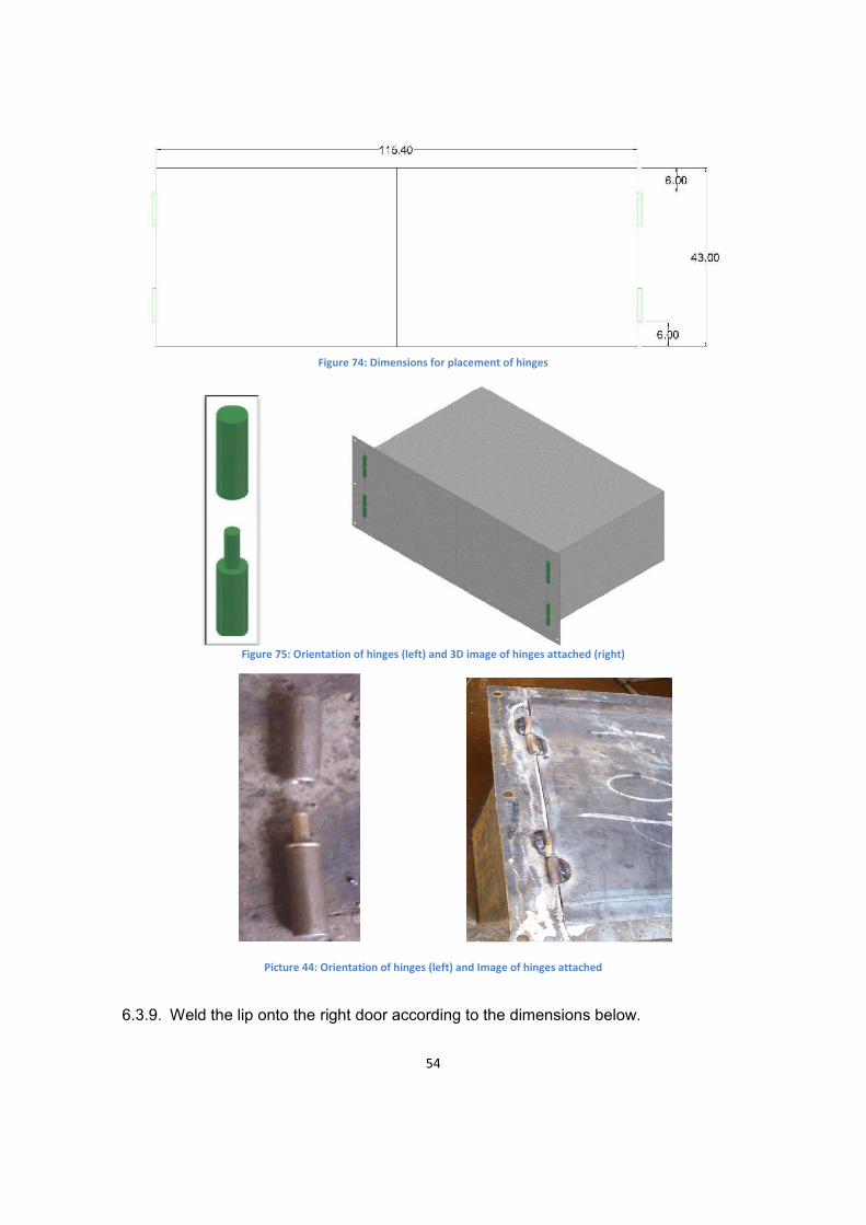
6.3.8. Weld the 4 hinges onto the doors according to the dimensions below. Making sure that
the orientation of the hinges is correct (see Figure 76). Also the top of each hinge should be welded to the door and the bottom should be welded to the baking chamber flange
54
Figure 74: Dimensions for placement of hinges
Figure 75: Orientation of hinges (left) and 3D image of hinges attached (right)
Picture 44: Orientation of hinges (left) and Image of hinges attached
6.3.9. Weld the lip onto the right door according to the dimensions below.

55
Figure 76: Dimensions for lip on left door
Figure 77: 3D image of lip added to right door
Picture 45: Image of lip added to right door

56
6.3.10. Attach three pieces of 2x2cm square bar together to form a handle according to the dimensions below.
Figure 78: Dimensions for handle (left) 3D image of handle (right)
Picture 46: Image of handle
6.3.11. Repeat step 5.3.10 to create another handle 6.3.12. Attach the handles to the doors according to the dimensions and images below.
Figure 79: Dimensions for the placement of the handles
57
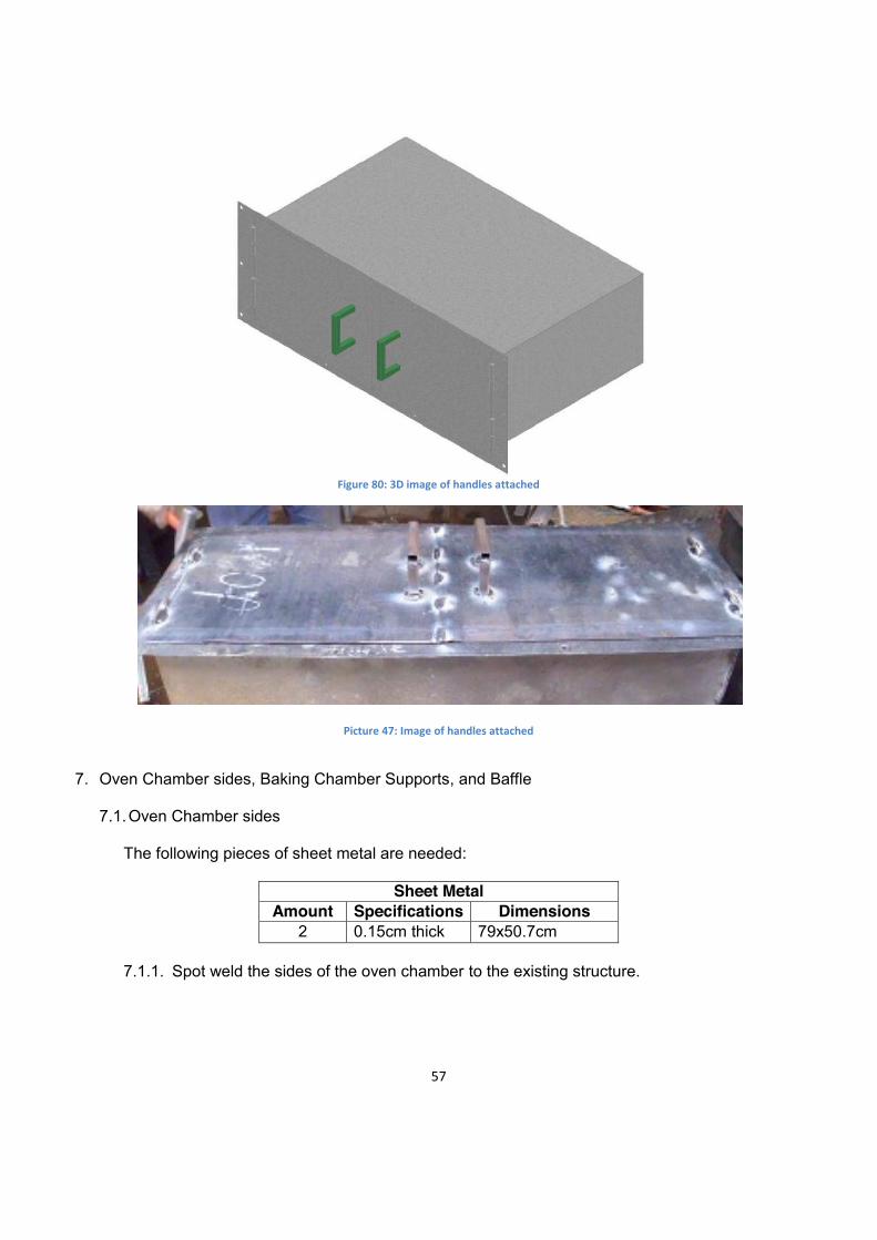
Figure 80: 3D image of handles attached
Picture 47: Image of handles attached
7. Oven Chamber sides, Baking Chamber Supports, and Baffle
7.1. Oven Chamber sides
The following pieces of sheet metal are needed:
Sheet Metal Amount Specifications Dimensions
2 0.15cm thick 79x50.7cm
7.1.1. Spot weld the sides of the oven chamber to the existing structure.
58
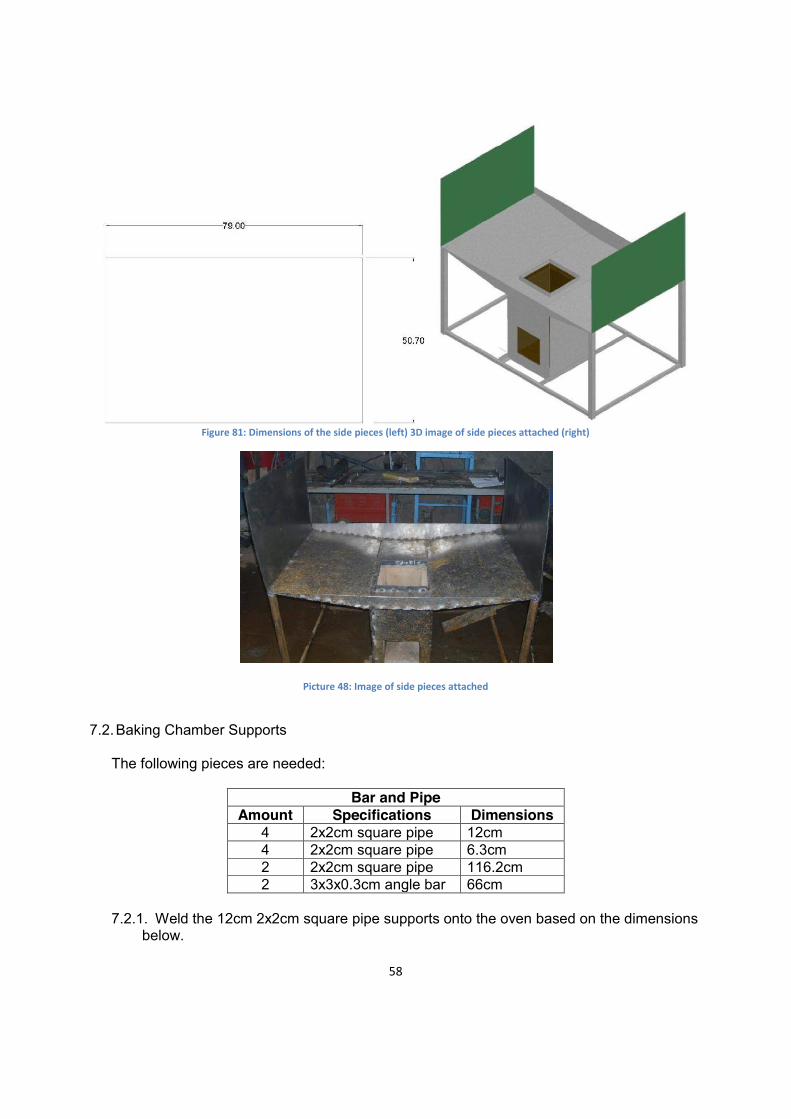
Figure 81: Dimensions of the side pieces (left) 3D image of side pieces attached (right)
Picture 48: Image of side pieces attached
7.2. Baking Chamber Supports
The following pieces are needed:
Bar and Pipe
Amount Specifications Dimensions 4 2x2cm square pipe 12cm 4 2x2cm square pipe 6.3cm 2 2x2cm square pipe 116.2cm 2 3x3x0.3cm angle bar 66cm
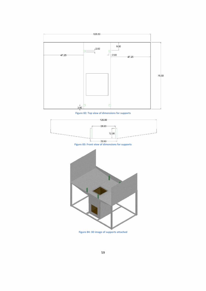
7.2.1. Weld the 12cm 2x2cm square pipe supports onto the oven based on the dimensions
below.
59
Figure 82: Top view of dimensions for supports
Figure 83: Front view of dimensions for supports
Figure 84: 3D image of supports attached
60
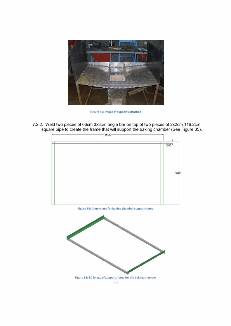
Picture 49: Image of supports attached
7.2.2. Weld two pieces of 66cm 3x3cm angle bar on top of two pieces of 2x2cm 116.2cm
square pipe to create the frame that will support the baking chamber (See Figure 85).
Figure 85: Dimensions for baking chamber support frame
Figure 86: 3D image of support frame for the baking chamber

61
Picture 50: Image of support frame for the baking chamber
7.2.3. Place the frame, shown above, on top of the supports. Temporarily spot weld on the
four supports. Stronger welds will be completed after checking the baking chamber on the support frame.
Figure 87: Dimensions for the placement of the support frame

62
Figure 88: 3D view of frame attached to supports
Picture 51: Image of frame attached to supports
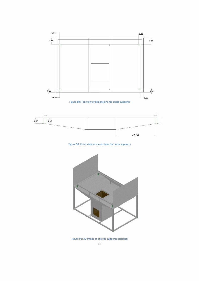
7.2.4. Temporarily spot weld the 6.3cm 2x2cm outer square pipe supports onto the oven and
frame based on the dimensions below. Stronger welds will be completed after checking the baking chamber on the support frame.
63
Figure 89: Top view of dimensions for outer supports
Figure 90: Front view of dimensions for outer supports
Figure 91: 3D image of outside supports attached

64
Picture 52: Image of attached outer supports (left) and close up of outer support on frame (right)
7.2.5. Spot weld the oven chamber flange to the oven with the bolts pointing outwards.
Figure 92:3D image of oven chamber lip attached
65
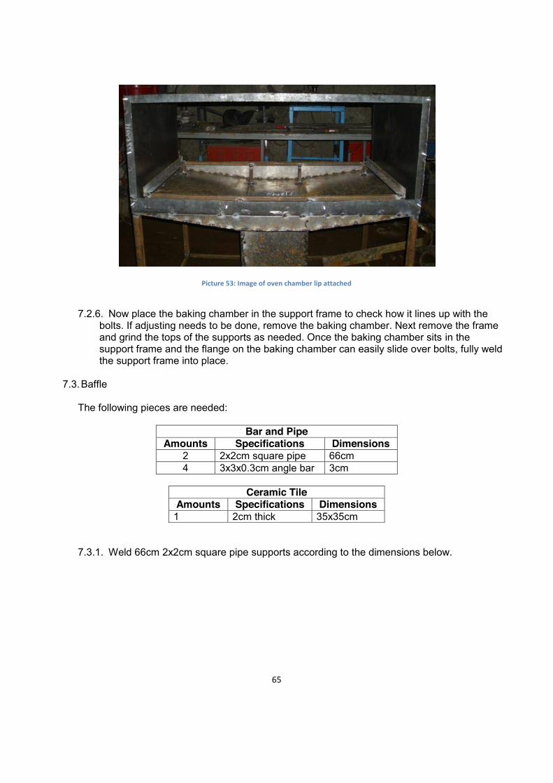
Picture 53: Image of oven chamber lip attached
7.2.6. Now place the baking chamber in the support frame to check how it lines up with the
bolts. If adjusting needs to be done, remove the baking chamber. Next remove the frame and grind the tops of the supports as needed. Once the baking chamber sits in the support frame and the flange on the baking chamber can easily slide over bolts, fully weld the support frame into place.
7.3. Baffle
The following pieces are needed:
Bar and Pipe
Amounts Specifications Dimensions 2 2x2cm square pipe 66cm 4 3x3x0.3cm angle bar 3cm
Ceramic Tile
Amounts Specifications Dimensions 1 2cm thick 35x35cm
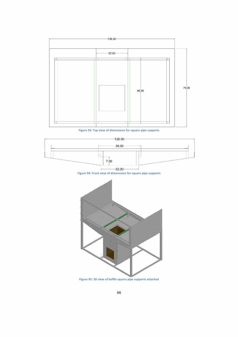
7.3.1. Weld 66cm 2x2cm square pipe supports according to the dimensions below.
66
Figure 93: Top view of dimensions for square pipe supports
Figure 94: Front view of dimensions for square pipe supports
Figure 95: 3D view of baffle square pipe supports attached
67
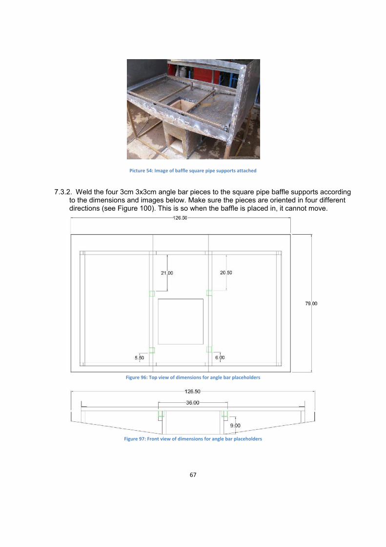
Picture 54: Image of baffle square pipe supports attached
7.3.2. Weld the four 3cm 3x3cm angle bar pieces to the square pipe baffle supports according
to the dimensions and images below. Make sure the pieces are oriented in four different directions (see Figure 100). This is so when the baffle is placed in, it cannot move.
Figure 96: Top view of dimensions for angle bar placeholders
Figure 97: Front view of dimensions for angle bar placeholders
68
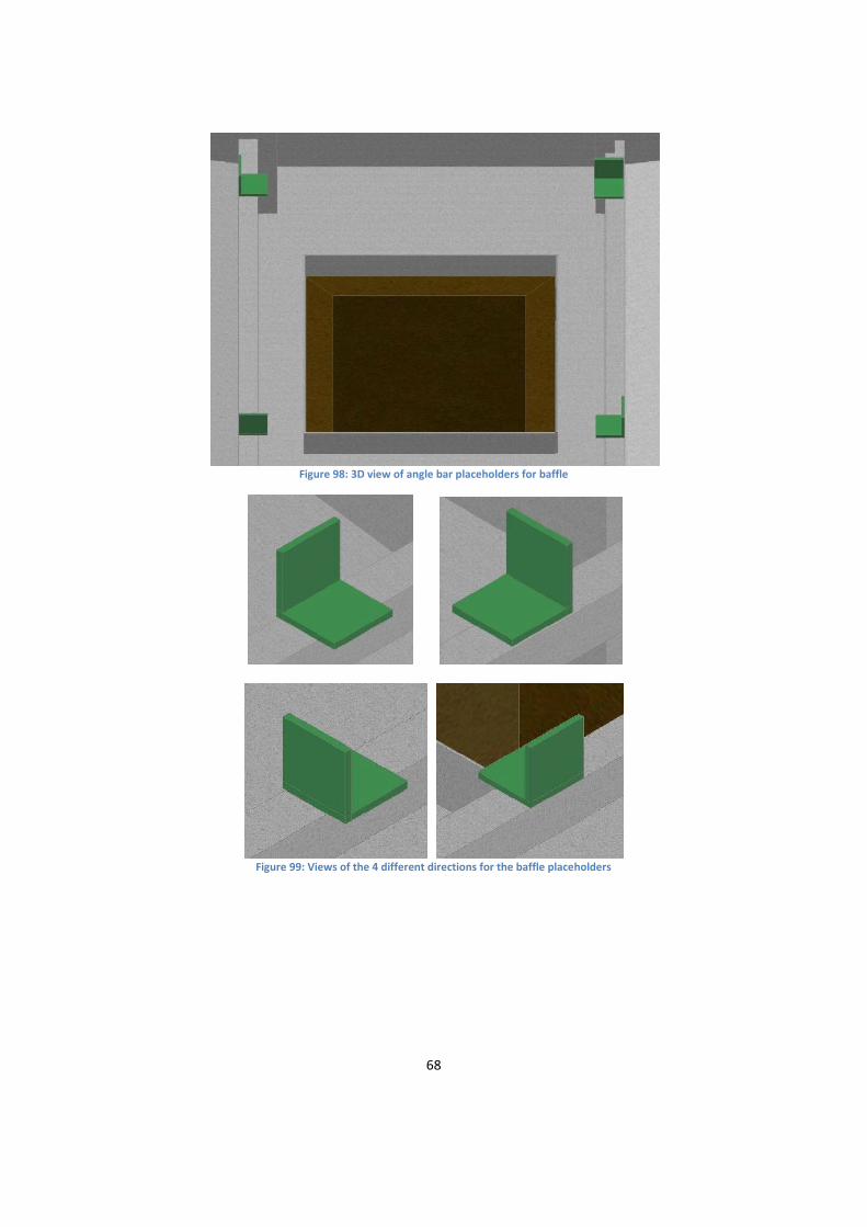
Figure 98: 3D view of angle bar placeholders for baffle
Figure 99: Views of the 4 different directions for the baffle placeholders
69
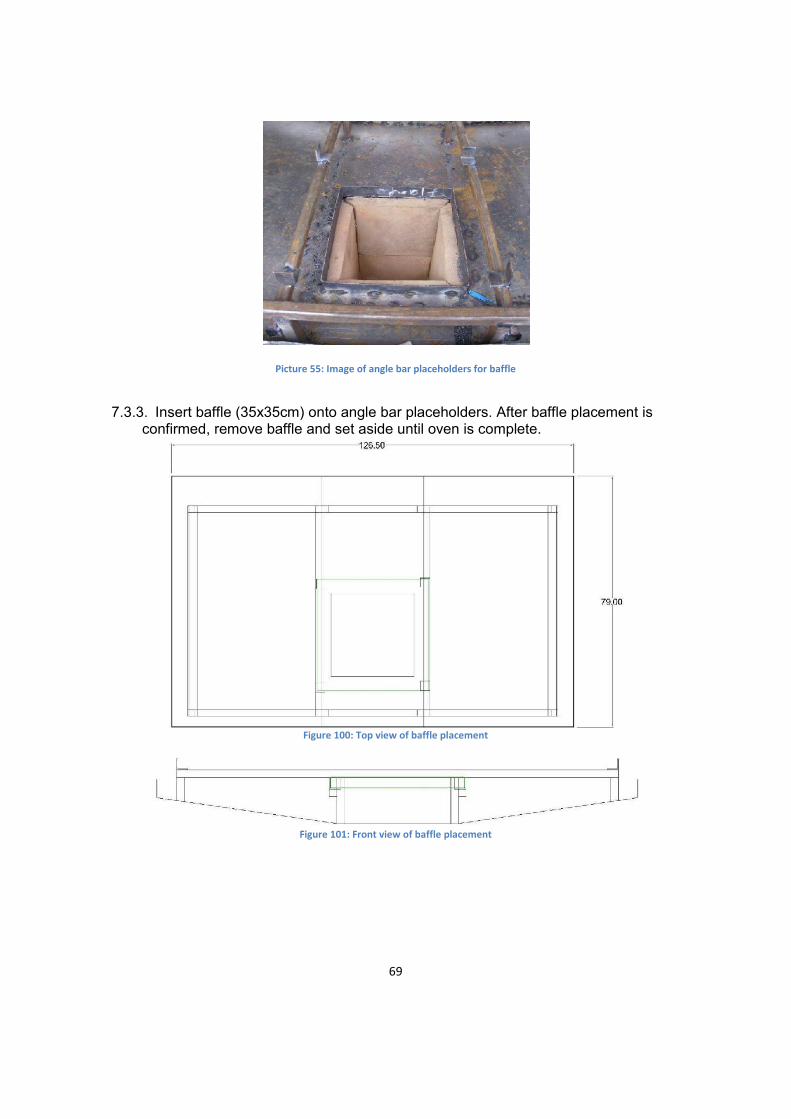
Picture 55: Image of angle bar placeholders for baffle
7.3.3. Insert baffle (35x35cm) onto angle bar placeholders. After baffle placement is
confirmed, remove baffle and set aside until oven is complete.
Figure 100: Top view of baffle placement
Figure 101: Front view of baffle placement

70
Figure 102: 3D view of baffle placement
8. Fiberglass Insulation Barrier and Fiberglass 8.1. Fiberglass Insulation Barrier
The following pieces of sheet metal and square pipe are needed:
Sheet Metal Amount Specifications Dimensions
1 .15cm thick 168.1x76.5cm 1 .15cm thick 198.1x46.5cm 1 .15cm thick 78.5x3cm
Pipe
Amount Specifications Dimensions 2 2x2cm square pipe 11.35cm 6 2x2cm square pipe 2.5cm
8.1.1. Chalk the folding lines on the pieces of sheet metal.

71
Figure 103: Folding line for the side and back of the insulation barrier
Figure 104: Folding lines for the top and side of the insulation barrier
8.1.2. Cut out a 25cm diameter circle out of the 168.1x76.5cm piece of sheet metal according to the dimensions below.
Figure 105: Dimensions for circle cut out
8.1.3. Fold along the chalked lines to form the side/back and the top/side pieces shown below.

72
Figure 106: 3D view of side/back piece (left) and top/side piece (right)
Picture 56: Image of side/back piece (left) and top/side piece (right)
8.1.4. Add 13.35cm 2x2cm square pipe supports according to the dimensions and images
below. The supports will attach to the back trapezoid.

73
Figure 107: Top view of dimensions for supports
Figure 108: Front view of dimensions for supports
Figure 109: Close-up view of supports (left) View of supports as relates to entire oven
(right)
74
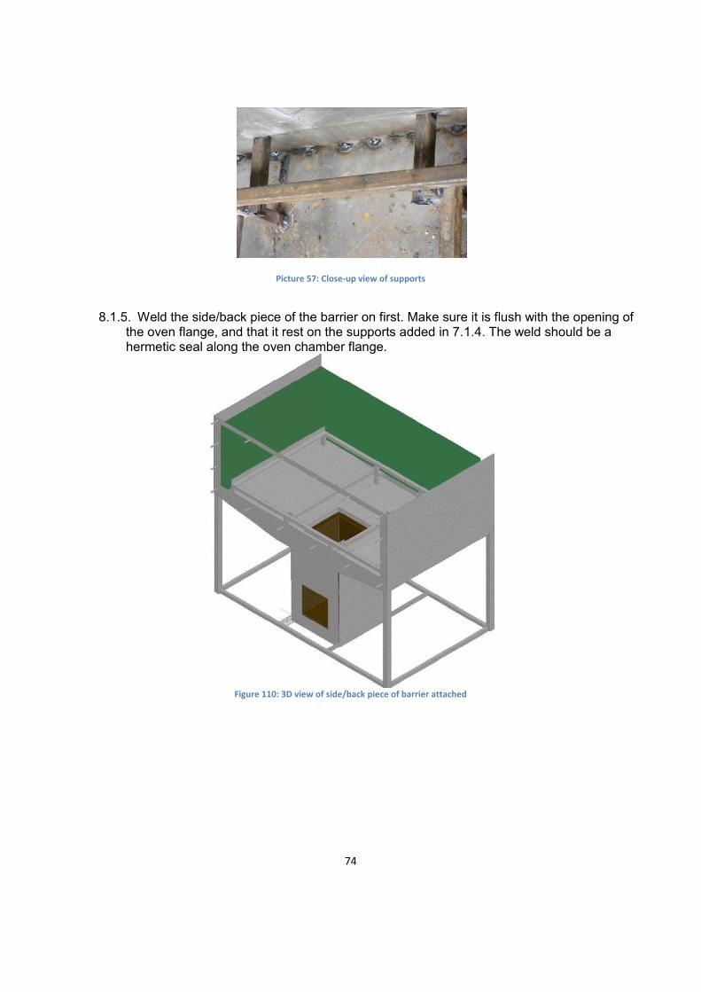
Picture 57: Close-up view of supports
8.1.5. Weld the side/back piece of the barrier on first. Make sure it is flush with the opening of
the oven flange, and that it rest on the supports added in 7.1.4. The weld should be a hermetic seal along the oven chamber flange.
Figure 110: 3D view of side/back piece of barrier attached

75
Picture 58: Image of side/back piece of barrier attached
8.1.6. Weld the side/top piece to the other side/back piece of the barrier. Also weld it to the
opening of the oven flange. The weld should be hermetic seal.
Figure 111: 3D view of side/top piece attached

76
Picture 59: Image of side/top piece attached
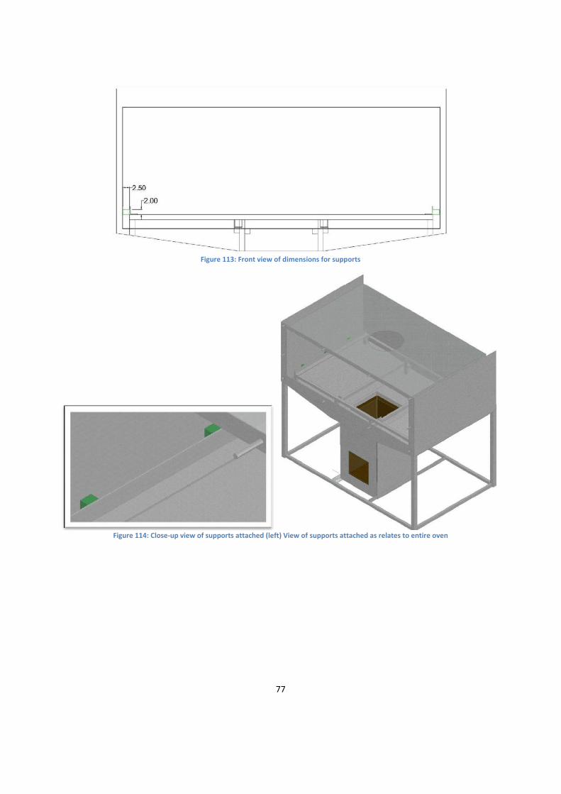
8.1.7. Add six 2.5cm 2x2cm square pipe supports in between the baking chamber supports
and the barrier to ensure the flue gas gap remains the same.
Figure 112: Top view of the dimensions for the 6 square pipe supports
77
Figure 113: Front view of dimensions for supports
Figure 114: Close-up view of supports attached (left) View of supports attached as relates to entire oven

78
Picture 60: Close-up image of supports attached (left) image of supports attached as relates to entire oven
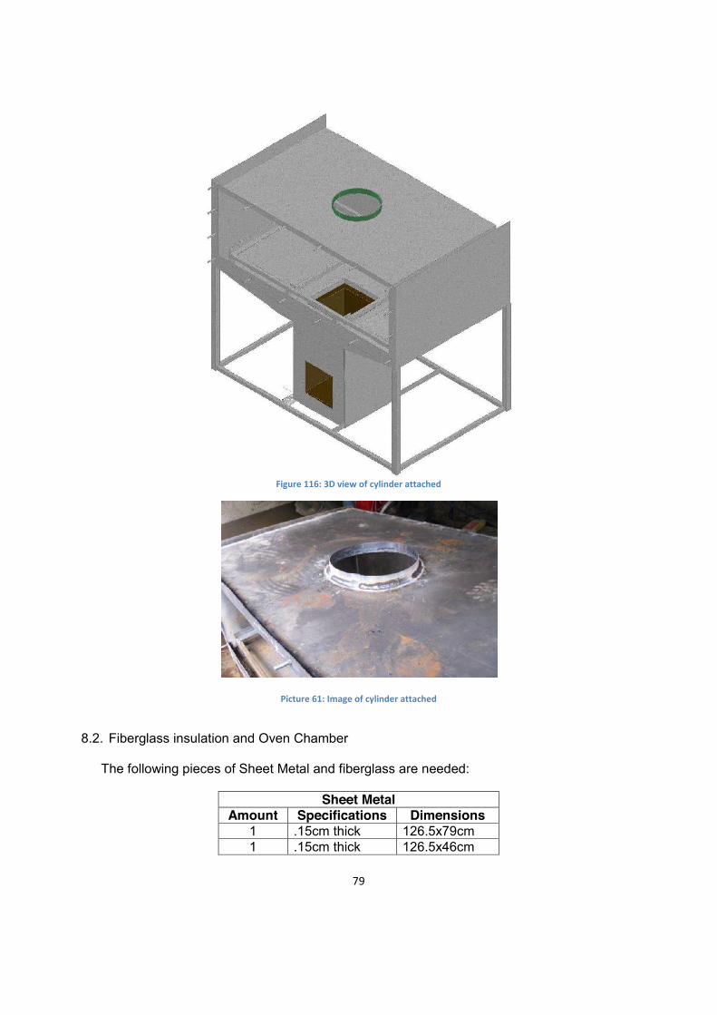
8.1.8. Hermetic weld 80x2.5cm piece of sheet metal to open circle on the top of the insulation
barrier to create a 2.5cm deep, 25cm diameter cylinder.
Figure 115: Dimensions of cylinder
79
Figure 116: 3D view of cylinder attached
Picture 61: Image of cylinder attached
8.2. Fiberglass insulation and Oven Chamber
The following pieces of Sheet Metal and fiberglass are needed:
Sheet Metal
Amount Specifications Dimensions 1 .15cm thick 126.5x79cm 1 .15cm thick 126.5x46cm

80
Fiberglass Amount Specifications Dimensions
2 2.5cm thick 79x50cm 1 2.5cm thick 121.5x50cm 1 2.5 cm thick 126.5x79cm
8.2.1. Insert the 79x50cm sheets of fiberglass into the side slots.
Figure 117: 3D image of fiberglass sides inserted
Picture 62: Image of fiberglass sides inserted (left) and close up of side with fiberglass inserted

81
8.2.2. Weld the 126.5x46cm back panel onto the oven chamber.
Figure 118: 3D image of back piece attached
8.2.3. Insert 121.5x50cm piece of fiberglass into the back slot
Figure 119: 3D image of back piece of fiberglass inserted
82
Picture 63: Image of back piece of fiberglass inserted
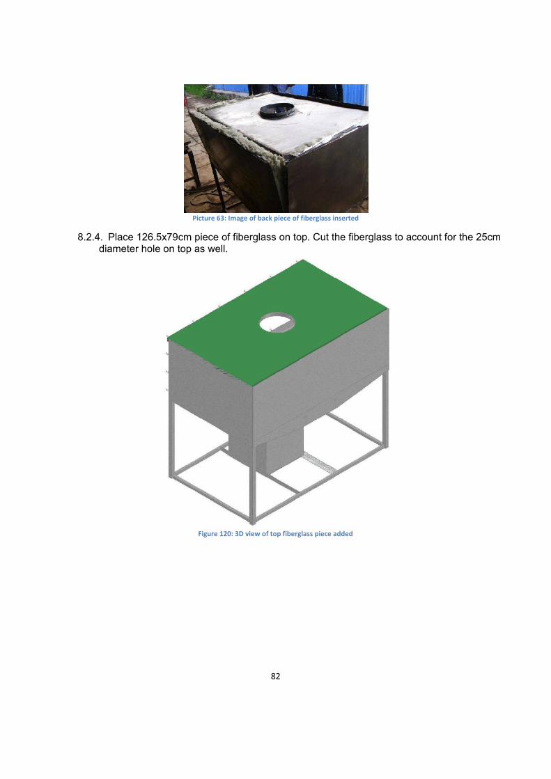
8.2.4. Place 126.5x79cm piece of fiberglass on top. Cut the fiberglass to account for the 25cm diameter hole on top as well.
Figure 120: 3D view of top fiberglass piece added
83
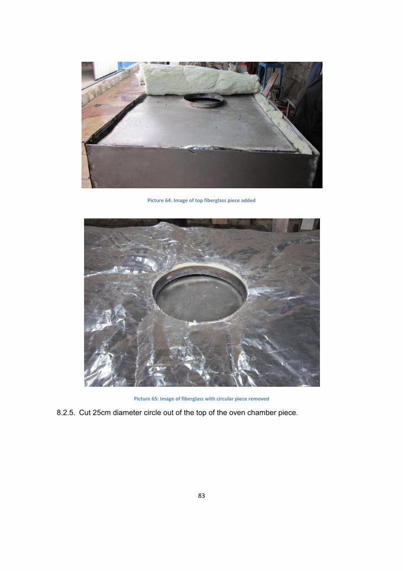
Picture 64: Image of top fiberglass piece added
Picture 65: Image of fiberglass with circular piece removed
8.2.5. Cut 25cm diameter circle out of the top of the oven chamber piece.

84
Figure 121: Dimensions for circle cut-out of the top oven chamber piece
8.2.6. Weld top of the oven chamber on. The weld should be a hermetic seal around the circle, but only spot welded around the exterior edges.
Figure 122: 3D image of the top of the oven chamber attached
9. Manifold and Chimney
9.1. Manifold
Sheet Metal Amount Specifications Dimensions
1 .15cm thick Outside Radius 21.5 cm Inside Radius 12.9 (See figure 121)
85
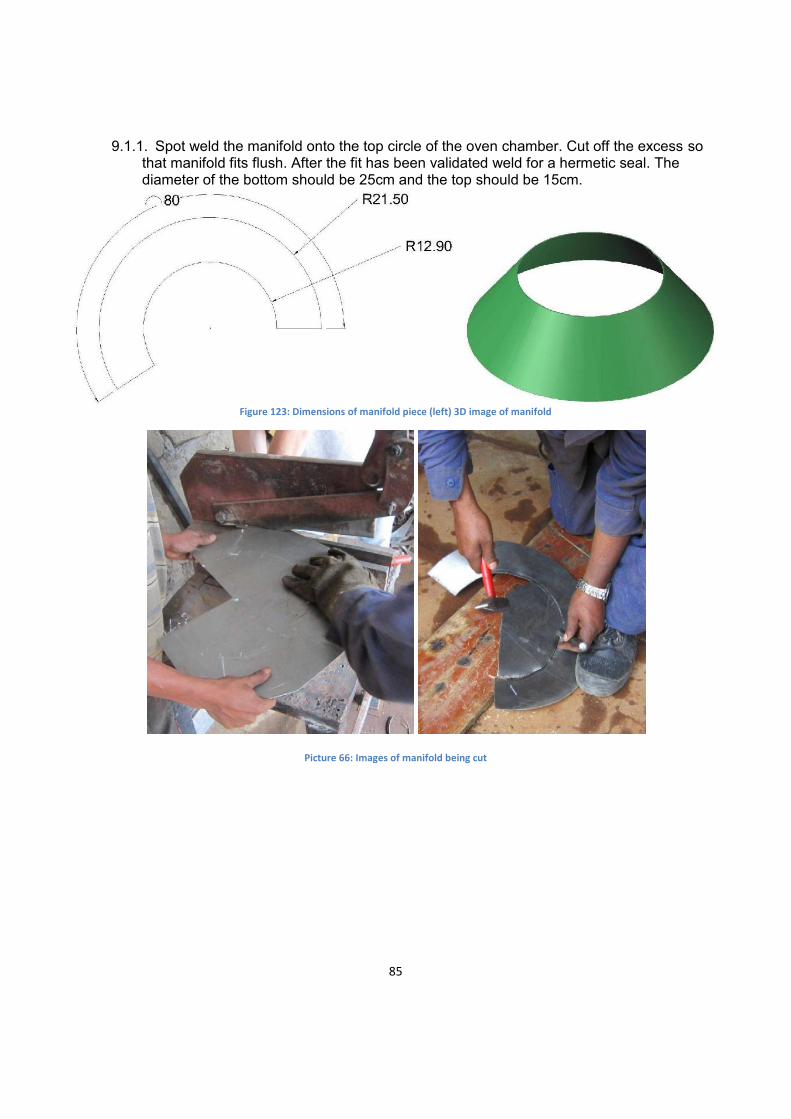
9.1.1. Spot weld the manifold onto the top circle of the oven chamber. Cut off the excess so
that manifold fits flush. After the fit has been validated weld for a hermetic seal. The diameter of the bottom should be 25cm and the top should be 15cm.
Figure 123: Dimensions of manifold piece (left) 3D image of manifold
Picture 66: Images of manifold being cut

86
Picture 67: Images of manifold shaped to fit hole (left) photo of manifold spot welded on with excess material (right)
Picture 68: Images of the welding for a hermetic seal
87
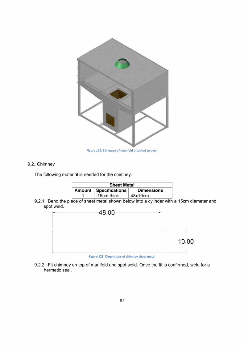
Figure 124: 3D image of manifold attached to oven
9.2. Chimney
The following material is needed for the chimney:
Sheet Metal
Amount Specifications Dimensions 1 .15cm thick 48x10cm
9.2.1. Bend the piece of sheet metal shown below into a cylinder with a 15cm diameter and spot weld.
Figure 125: Dimensions of chimney sheet metal
9.2.2. Fit chimney on top of manifold and spot weld. Once the fit is confirmed, weld for a hermetic seal.

88
Picture 69: Images of chimney welded for a hermetic seal
Figure 126: 3D image with chimney attached
10. Grate and Ash Remover 10.1. Review (Optional) Ceramic grate in section 16 before continuing. 10.2. Grate The following materials are needed:
Round Bar and Pipe Amount Specifications Dimensions
1 1 cm diameter 154cm 4 1 cm diameter 22cm 2 1 cm diameter 18cm 2 1 cm diameter 13cm
89
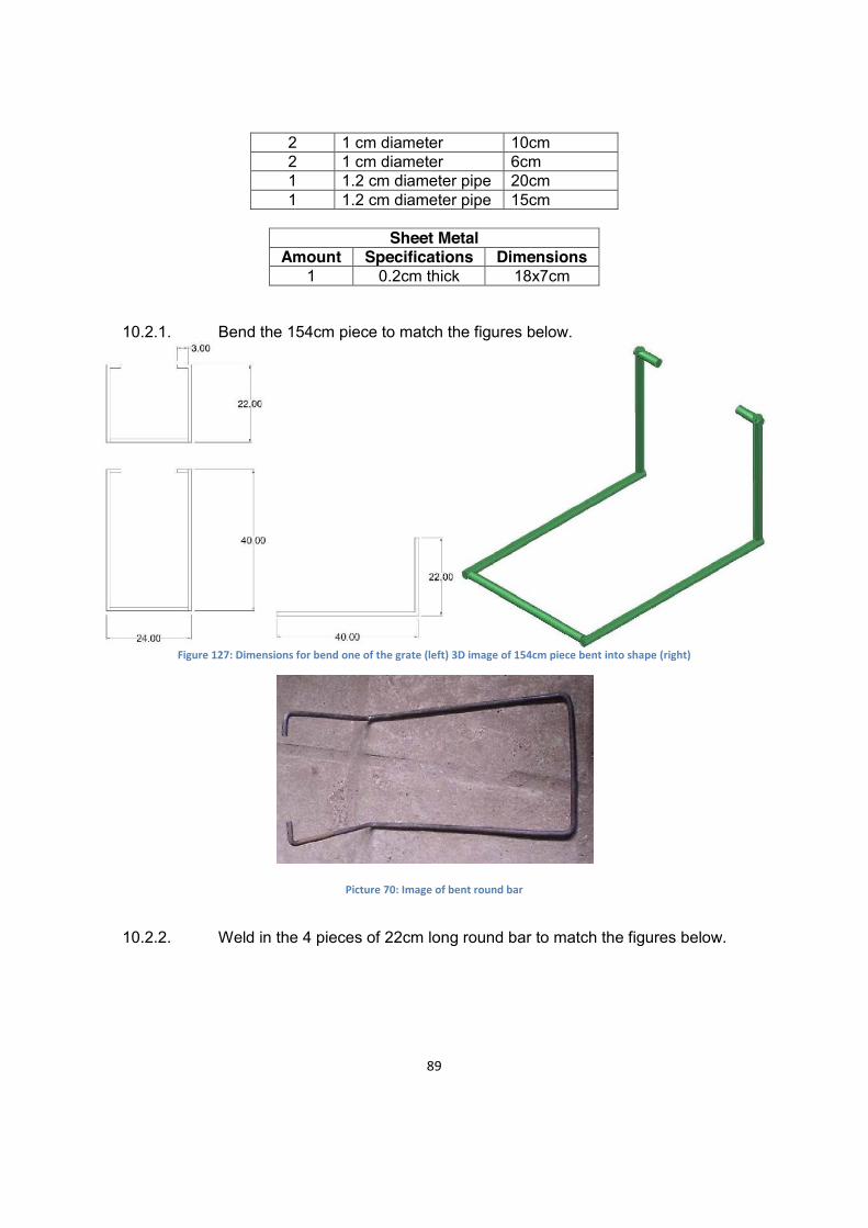
2 1 cm diameter 10cm 2 1 cm diameter 6cm 1 1.2 cm diameter pipe 20cm 1 1.2 cm diameter pipe 15cm
Sheet Metal
Amount Specifications Dimensions 1 0.2cm thick 18x7cm
10.2.1. Bend the 154cm piece to match the figures below.
Figure 127: Dimensions for bend one of the grate (left) 3D image of 154cm piece bent into shape (right)
Picture 70: Image of bent round bar
10.2.2. Weld in the 4 pieces of 22cm long round bar to match the figures below.

90
Figure 128: Dimensions for 4 pieces of round bar (left) 3D image of round bar pieces attached (right)
Picture 71: Image of round bar pieces attached
10.2.3. Insert the 20cm 1.2cm metal tube as shown below.

91
Figure 129: Images for the placement of metal tube
Picture 72: Images for attached metal tube
10.2.4. Add a 6cm piece of round bar according to the figures below.

92
Figure 130: Dimensions (left) 3D image of the back piece attached (right)
Picture 73: Image of the back piece attached
10.2.5. Add the 18cm round bar piece according to the images below.

93
Figure 131: Dimensions for 18cm round bar piece (left) 3D image of the piece attached (right)
Picture 74: Image of the 18cm round bar piece attached
10.2.6. Slide on 15cm 1.2cm metal tube as shown below.
94
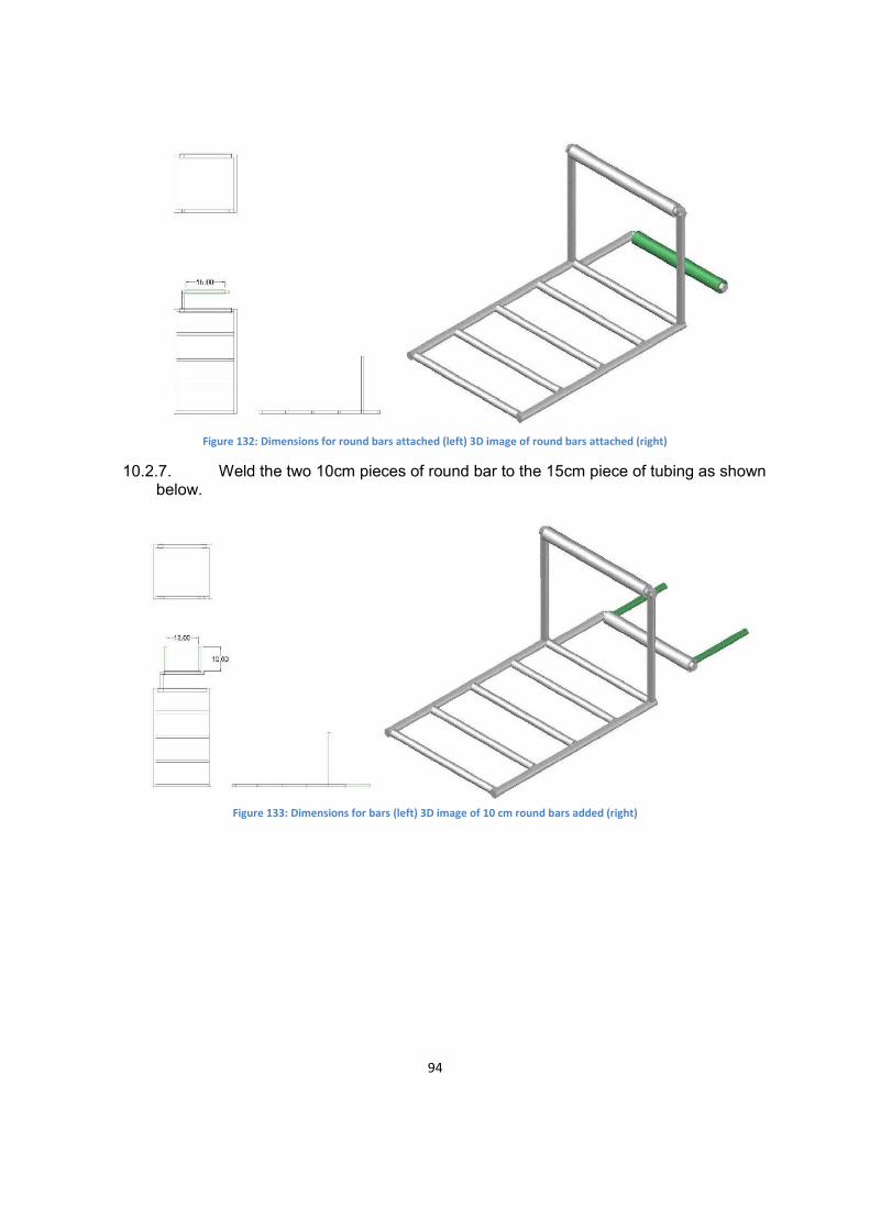
Figure 132: Dimensions for round bars attached (left) 3D image of round bars attached (right)
10.2.7. Weld the two 10cm pieces of round bar to the 15cm piece of tubing as shown below.
Figure 133: Dimensions for bars (left) 3D image of 10 cm round bars added (right)
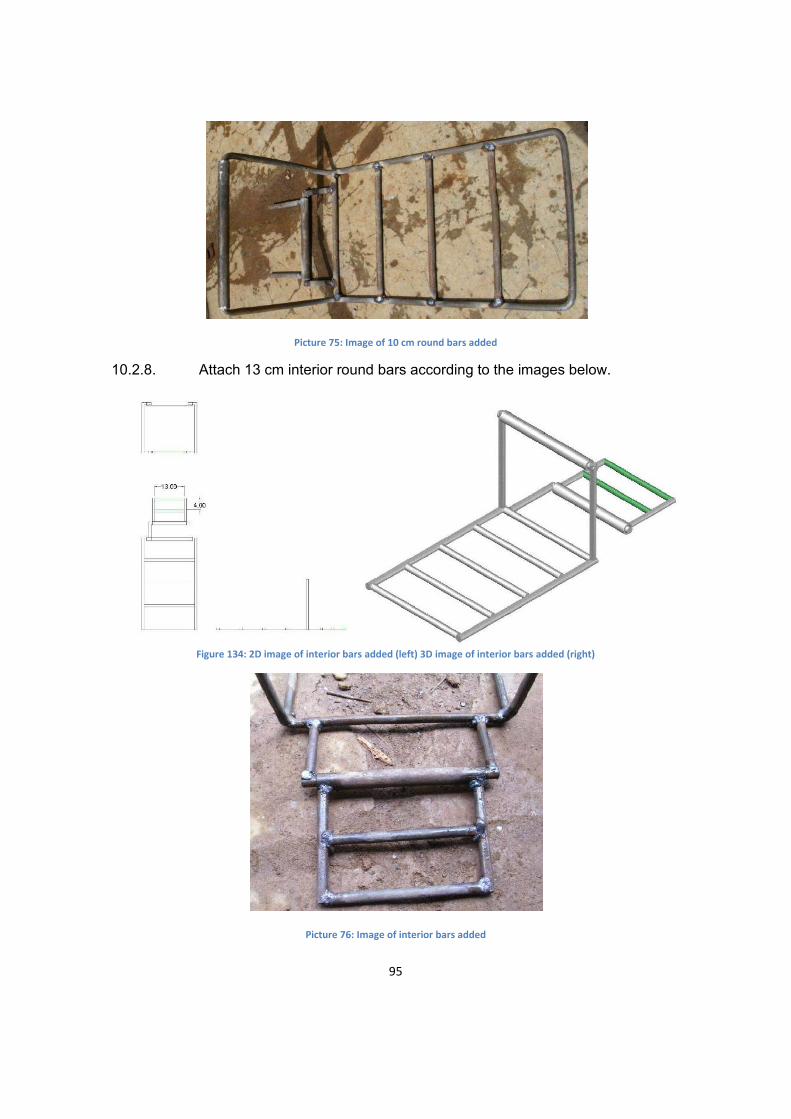
95
Picture 75: Image of 10 cm round bars added
10.2.8. Attach 13 cm interior round bars according to the images below.
Figure 134: 2D image of interior bars added (left) 3D image of interior bars added (right)
Picture 76: Image of interior bars added

96
10.2.9. Weld other 6cm piece of round bar on according to the images below.
Figure 135: Dimensions for 6cm piece of round bar (left) 3D image of 6cm round bar attached (right)
10.2.10. Weld 7x18cm 0.2cm thick piece of sheet metal to grate according to the dimensions below for the extension support.
Figure 136: Dimensions for support pieces (left) 3D image of support (right)
97
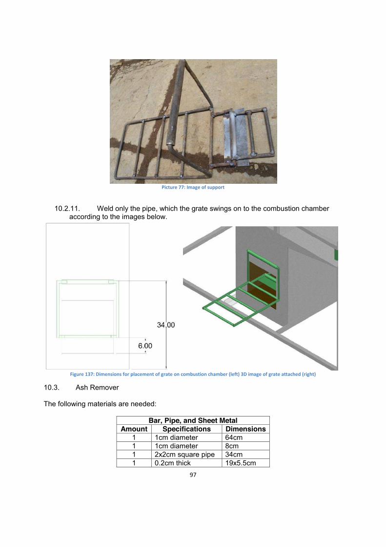
Picture 77: Image of support
10.2.11. Weld only the pipe, which the grate swings on to the combustion chamber
according to the images below.
Figure 137: Dimensions for placement of grate on combustion chamber (left) 3D image of grate attached (right)
10.3. Ash Remover
The following materials are needed:
Bar, Pipe, and Sheet Metal Amount Specifications Dimensions
1 1cm diameter 64cm 1 1cm diameter 8cm 1 2x2cm square pipe 34cm 1 0.2cm thick 19x5.5cm
98
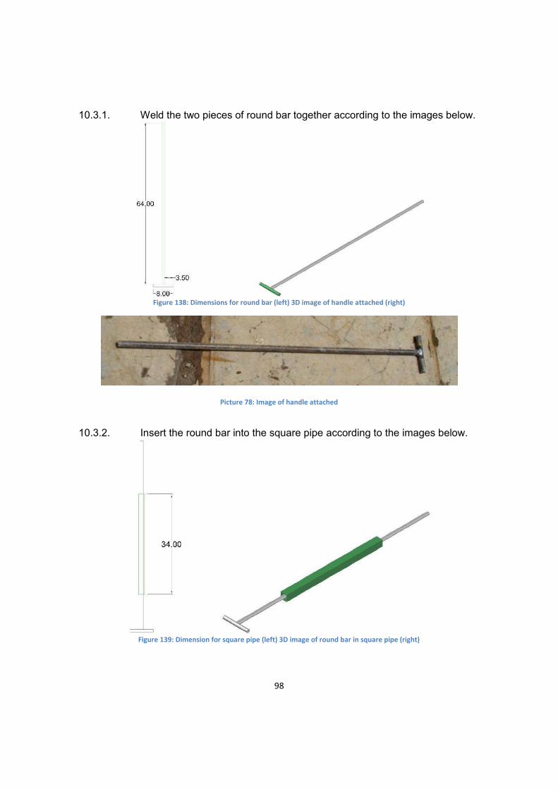
10.3.1. Weld the two pieces of round bar together according to the images below.
Figure 138: Dimensions for round bar (left) 3D image of handle attached (right)
Picture 78: Image of handle attached
10.3.2. Insert the round bar into the square pipe according to the images below.
Figure 139: Dimension for square pipe (left) 3D image of round bar in square pipe (right)
99
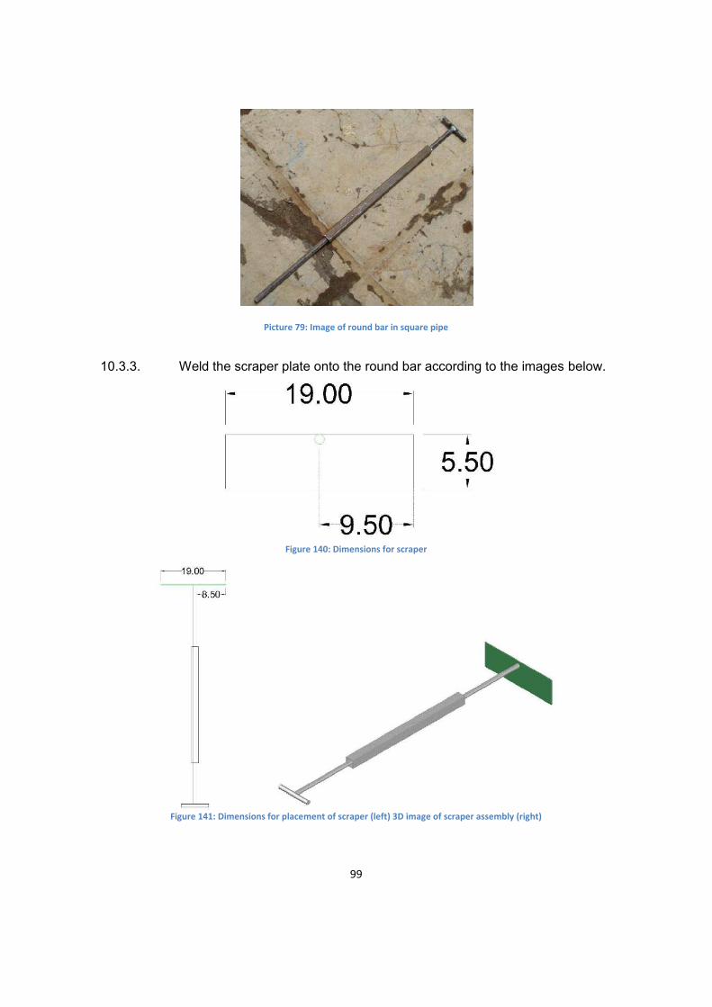
Picture 79: Image of round bar in square pipe
10.3.3. Weld the scraper plate onto the round bar according to the images below.
Figure 140: Dimensions for scraper
Figure 141: Dimensions for placement of scraper (left) 3D image of scraper assembly (right)

100
Picture 80: Image of scraper assembly
10.3.4. Weld the scraper assembly onto the grate according to the images below.
Figure 142: Dimension for scraper assembly placement (left) 3D image of scraper assembly attached (right)
11. Latches The following materials are needed for the latches:
Latches Amount Specifications Dimensions
2 1.2cm diameter round bar 20cm 2 0.5cm thick plate 12.5x2.5cm 2 0.6cm diameter round bar 14cm 4 1.5cm inside diameter tube
with 4mm thickness 2.5cm
11.1. Weld the 1.2cm diameter piece of round bar to the 0.5cm thick, 12.5cm long plate
according to the image below.

101
Figure 143: Dimensions for latch assembly
Picture 81: Latch assembly
11.2. Repeat step 10.1 to construct another latch. 11.3. Weld half of a 1.5cm diameter pipe, 2.5cm long onto the oven doors according to the
images below.
Figure 144: Dimensions for bottom holders

102
Figure 145: 3D image of bottom holders attached
11.4. Place latches in holders
Figure 146: Latches placed in holders

103
Figure 147: 3D image of latches added
11.5. Weld more of the 2.5cm 1.5cm diameter pipe, cut in half, to the doors according to the images below
Figure 148: Dimensions for the top holders

104
Figure 149: 3D image of top holders attached
11.6. Weld the latch catches on according to the images below. The round bar should be at least 2cm out from the door in order to catch the latch. The round bar diameter is 0.6cm.
Figure 150: Dimensions for the latch catches
11.7. Bend 14cm .6 diameter round bar to the dimensions below.
11.8. Weld bent round bar pieces onto the oven chamber flange according to the images below.

105
Figure 151: Dimensions for the holders attached to the oven chamber flange
11.9. Test the latches to make sure they work properly
Picture 82: Images of latch in open position (left) and closed position (right)
12. (Optional) Additional Base
12.1. The following pieces of square pipe are needed:
Square Pipe Amount Specifications Dimensions
2 2x2cm 166.5cm 2 2x2cm 75cm 2 3x3cm 75cm 4 3x3cm 28cm
106
4 2x2cm 28cm 4 2x2cm 33.65cm
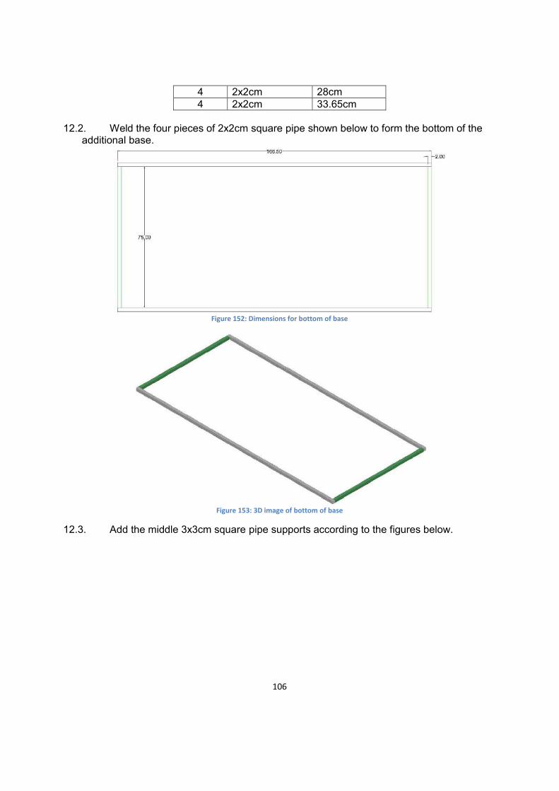
12.2. Weld the four pieces of 2x2cm square pipe shown below to form the bottom of the
additional base.
Figure 152: Dimensions for bottom of base
Figure 153: 3D image of bottom of base
12.3. Add the middle 3x3cm square pipe supports according to the figures below.

107
Figure 154: Dimensions for 3x3cm square pipe supports
Figure 155: 3D image of 3x3cm square pipe supports attached
12.4. Weld the four, 3x3cm square pipe, combustion chamber supports on according to the figures below.

108
Figure 156: Front view of dimensions for combustion chamber supports (top) Top view of dimensions for combustion chamber supports
(bottom)
Figure 157: 3D image of combustion chamber supports attached
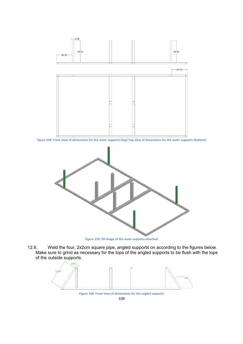
12.5. Weld the four, 2x2cm square pipe, outer supports on according to the figures below.
109
Figure 158: Front view of dimensions for the outer supports (top) Top view of dimensions for the outer supports (bottom)
Figure 159: 3D image of the outer supports attached
12.6. Weld the four, 2x2cm square pipe, angled supports on according to the figures below. Make sure to grind as necessary for the tops of the angled supports to be flush with the tops of the outside supports.
Figure 160: Front view of dimensions for the angled supports

110
Figure 161: 3D view of angled supports attached
12.7. The additional base can be added after step 1.8. When the oven is completed the additional base will look like the figure below. The additional base is not pictured in the previous steps because not all circumstances will require additional height.
Figure 162: Additional base attached, picture is shown without the baking chamber inserted
13. Sanding and Painting 13.1. Sand any pieces of metal that might have rusted during construction.

111
Picture 83: Images of sanding
13.2. After sanding is complete paint the exterior of the oven. Make sure not to paint any of the interior of the baking chamber. Due to the flumes, the bread baked in the oven would be inedible if the interior was painted.
Picture 84: Images of painting
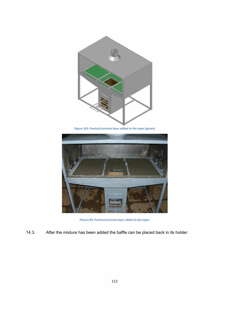
14. Pumice/Concrete 14.1. Create a mixture of 1 part concrete and 5 parts pumice. 14.2. Add a 3cm deep layer of the pumice/concrete mixture to the taper, making sure the
mixture is not higher than the lip above the combustion chamber.
112
Figure 163: Pumice/concrete layer added to the taper (green)
Picture 85: Pumice/concrete layer added to the taper
14.3. After the mixture has been added the baffle can be placed back in its holder.
113
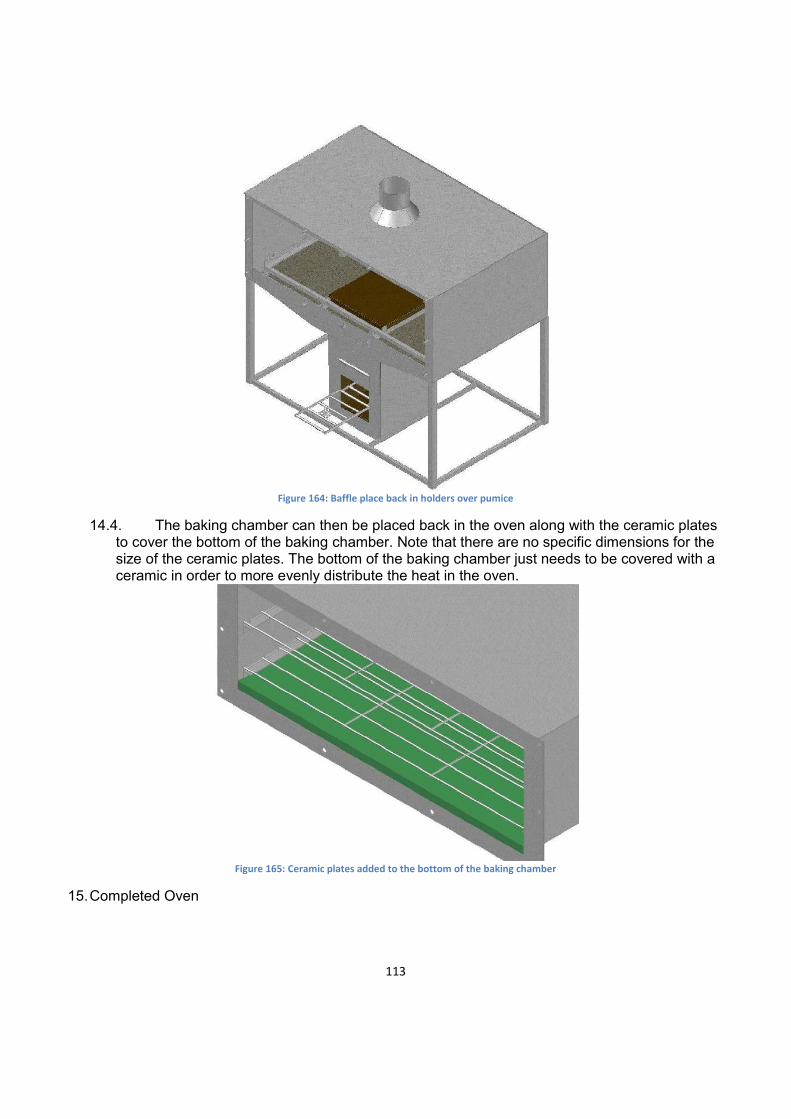
Figure 164: Baffle place back in holders over pumice
14.4. The baking chamber can then be placed back in the oven along with the ceramic plates to cover the bottom of the baking chamber. Note that there are no specific dimensions for the size of the ceramic plates. The bottom of the baking chamber just needs to be covered with a ceramic in order to more evenly distribute the heat in the oven.
Figure 165: Ceramic plates added to the bottom of the baking chamber
15. Completed Oven

114
Figure 166: Completed Oven (left) Completed oven with additional base (right)
Picture 86: Completed Oven
16. Cleaning Procedure An efficient and clean burning oven is dependent on adequate air flow into the combustion chamber and out of the chimney. A byproduct of normal operation is soot. Periodically, soot will accumulate in

115
the in the flow path of hot flue gas and need to be removed. The baking chamber can be removed to accommodate soot removal. Schedule cleaning will insure proper performance.
15.1 Remove doors
Picture 87: Image of door removal
15.2 Remove racks and clay tiles lining the bottom of the oven
Picture 88: Image of rack removal
15.2 Remove nuts and washers from bolts and slide baking chamber out of the oven body
Picture 89: Image of bolt (left) and baking chamber (right) removal
15.3 Wipe down inside of oven with cloth to remove soot and ash.
116
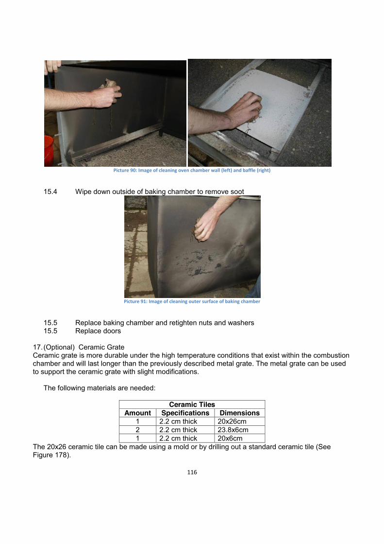
Picture 90: Image of cleaning oven chamber wall (left) and baffle (right)
15.4 Wipe down outside of baking chamber to remove soot
Picture 91: Image of cleaning outer surface of baking chamber
15.5 Replace baking chamber and retighten nuts and washers 15.5 Replace doors
17. (Optional) Ceramic Grate Ceramic grate is more durable under the high temperature conditions that exist within the combustion chamber and will last longer than the previously described metal grate. The metal grate can be used to support the ceramic grate with slight modifications.
The following materials are needed:
Ceramic Tiles
Amount Specifications Dimensions 1 2.2 cm thick 20x26cm 2 2.2 cm thick 23.8x6cm 1 2.2 cm thick 20x6cm
The 20x26 ceramic tile can be made using a mold or by drilling out a standard ceramic tile (See Figure 178).
117
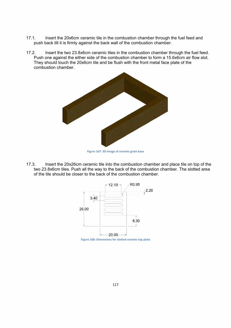
17.1. Insert the 20x6cm ceramic tile in the combustion chamber through the fuel feed and push back till it is firmly against the back wall of the combustion chamber.
17.2. Insert the two 23.8x6cm ceramic tiles in the combustion chamber through the fuel feed. Push one against the either side of the combustion chamber to form a 15.6x6cm air flow slot. They should touch the 20x6cm tile and be flush with the front metal face plate of the combustion chamber.
Figure 167: 3D Image of ceramic grate base
17.3. Insert the 20x26cm ceramic tile into the combustion chamber and place tile on top of the
two 23.8x6cm tiles. Push all the way to the back of the combustion chamber. The slotted area of the tile should be closer to the back of the combustion chamber.
Figure 168: Dimensions for slotted ceramic top plate

118
Figure 169: Completed ceramic grate
17.4. Skip sections 9.2.4 through 9.2.11 to construct a metal grate that supports the ceramic grate. The ash remover doesn’t need any modifications to work with ceramic grate.
Figure 170: Modified metal grate
18. (Optional) Silicon Gasket
18.1. Baking Chamber 17.1.1 Remove baking chamber 17.1.2 Add a bead of silicon on each side of oven flange. Silicon should be .5 cm form the
outer edge of the bolts 17.1.3 Allow the silicon to dry 17.1.4 Replace baking chamber 18.2. Baking Chamber Doors 17.2.1 Remove Baking Chamber Doors

119
17.2.2 Add a bead of silicon on the top and bottom edge of baking chamber flange. Silicon should be 1 cm from the inner edge flange
17.2.2 Allow the silicon to dry 17.2.3 Replace the doors