السقوف الشبكية الفراغية space & diagrid frames- design
TRANSCRIPT

1
A three-dimensional
structures
Dr Hammida
2
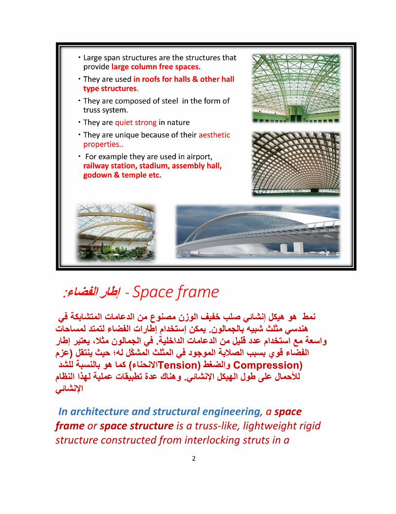
Space frame - :إطار الفضاء
إنشائي صلب خفیف الوزن مصنوع من الدعامات المتشابكة فيھو ھیكل نمط یمكن إستخدام إطارات الفضاء لتمتد لمساحات . بالجمالون ھندسي مثلث شبیھ
ت الداخلیة. في الجمالون مثال، یعتبر إطار واسعة مع استخدام عدد قلیل من الدعاما عزمالفضاء قوي بسبب الصالبة الموجود في المثلث المشّكل لھ؛ حیث ینتقل (
(Tension للشد كما ھو بالنسبة) االنحناء (Compression والضغط وھناك عدة تطبیقات عملیة لھذا النظام لألحمال على طول الھیكل اإلنشائي.
اإلنشائي
In architecture and structural engineering, a space frame or space structure is a truss-like, lightweight rigid structure constructed from interlocking struts in a
3
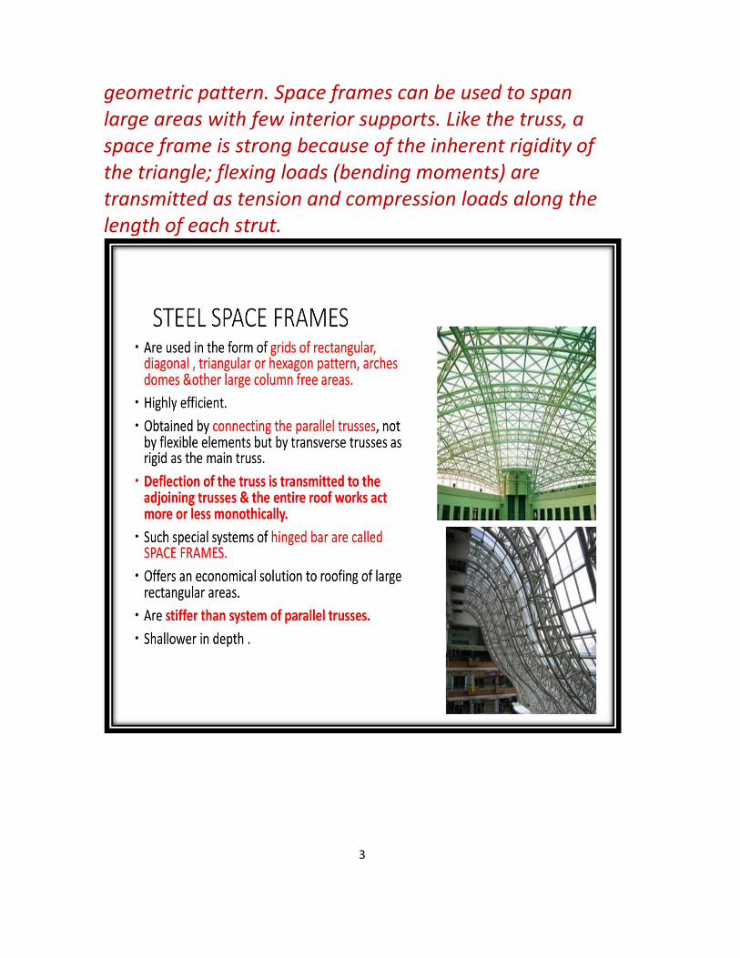
geometric pattern. Space frames can be used to span large areas with few interior supports. Like the truss, a space frame is strong because of the inherent rigidity of the triangle; flexing loads (bending moments) are transmitted as tension and compression loads along the length of each strut.

4
5
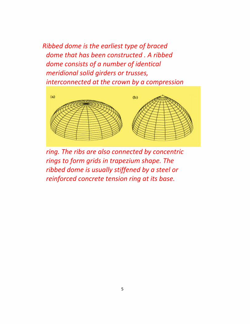
Ribbed dome is the earliest type of braced dome that has been constructed . A ribbed dome consists of a number of identical meridional solid girders or trusses, interconnected at the crown by a compression
ring. The ribs are also connected by concentric rings to form grids in trapezium shape. The ribbed dome is usually stiffened by a steel or reinforced concrete tension ring at its base.

6
7

8
SPACE FRAME

9
TYPES OF SPACE FRAME

10
TYPES OF SPACE FRAME
11
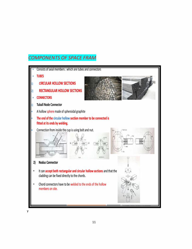
COMPONENTS OF SPACE FRAM
y

12

13
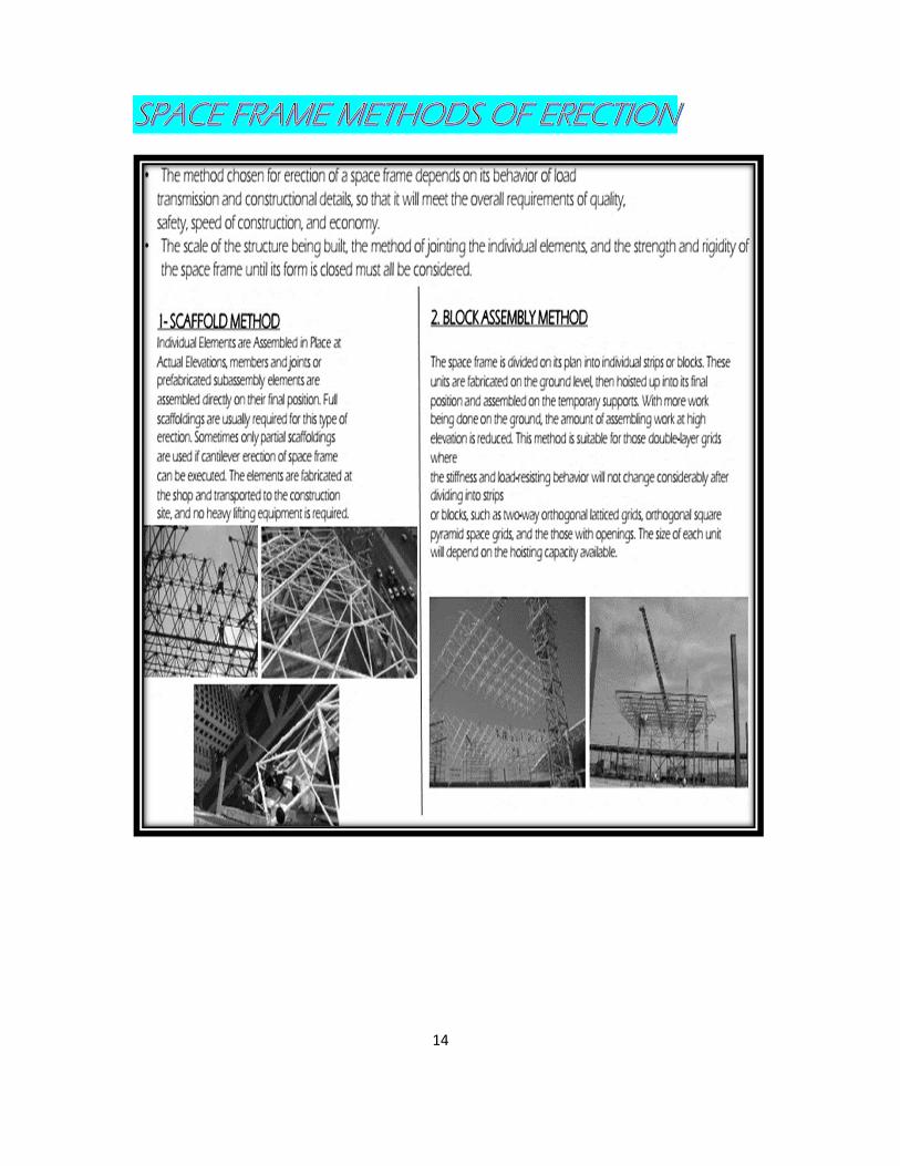
14

15
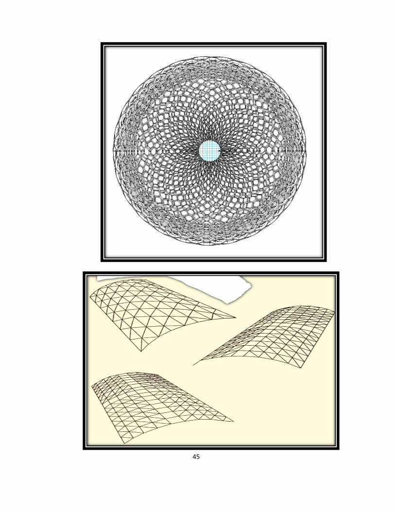
Custom Geometries
Novel building shapes are possible with Space Frame designs by
combining the basic geometries shown here. All of these can also be altered to
suit your aesthetic preference or to align with adjacent buildings or support locations. Building design often develops around rectilinear spaces & the benefits of curved roofs & walls can be overlooked.
Modern space frame design methods curved & complex shapes very competitive against more traditional linear roofs &
walls. allow us to expand the edges of domes (or any curved shape) to land on square, rectangular or any plan geometry. Advanced spaceframe manufacturing & construction techniques have made

16
In architecture and structural
engineering,
a space frame or space structure is a truss-like,
Lightweight rigid structure constructed from
interlocking struts in a geometric pattern.
Space frames can be used to span large areas with
few interior supports.

17
Like the truss, a space frame is strong because of
the inherent rigidity of the triangle; Flexing loads
(bending
moments) are transmitted as tension and
compression loads along the length of each strut.

18

19

20

21

22

23
24
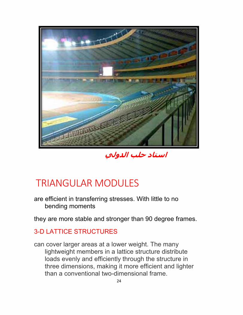
الدولي استاد حلب
TRIANGULAR MODULES
are efficient in transferring stresses. With little to no bending moments
they are more stable and stronger than 90 degree frames.
3-D LATTICE STRUCTURES
can cover larger areas at a lower weight. The many lightweight members in a lattice structure distribute loads evenly and efficiently through the structure in three dimensions, making it more efficient and lighter than a conventional two-dimensional frame.

25
DOUBLY CURVED GEOMETRIES
have the ability to span long distances. Their curvature transfers stresses more efficiently with little to no bending moments, making them stiffer than conventional flat surfaces. Doubly curved geometries now offer infinite possibilities of free-style designs.
Application Fields – Industrial Structures (Factory, Warehouses, Antrepo, Hangar etc.) – Sports Complexes(Swimming Pools, Sport halls, tribunes, etc.)
– Multipurpose Halls (Theatres, Concert Halls, Cinemas, Convention Centres, Exhibition Halls,etc.) – Hangar Buildings, Canopies, Stands etc. – Shopping centres, showrooms, transportation structures, school structures, etc. – Fair stands – Scaffoldings, load scaffoldings etc

26
1.

27
2.
28
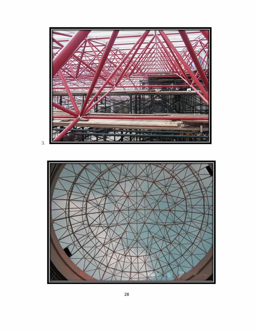
3.

29
. Space Frames
A space frame refers to a spatial structure whose members are connected rigidly to each other so that they transfer moment and shear in addition to axial forces. In comparison, space trusses are pin-jointed and as a result, their members are in tension or compression and do not transfer moment or shear.

30
In most cases, the additional reduction in member forces and deflection of space frames is less than 10% as compared to space trusses. Therefore, the additional material required to provide rigid connections does not justify the saving in the size of structural members. As a result, the term “space frame” is also the term used for pin-jointed three-dimensional structures, such as space trusses. Space frames are also called ‘braced frameworks’, ‘latticed structures’ or ‘reticulated structures’.
Space frames are either constructed from prefabricated modular units (modular system) or individual members assembled together using different types of connectors or nodes (nodular system). These systems are typically proprietary.
It is also possible to construct space frames by field-welding members to each other; this is
generally a more costly alternative. When field welding, the joints are considered to be rigidly connected, capable of transferring moment and
shear in addition to axial forces.
Nature has many examples of repetitive spatial packing configurations used in space frames: The hexagonal prisms of honeycomb; plant cell organisms, the repetitive organization of crystals and snowflakes, etc. The triangle is the simplest stable geometry, which means that it is not possible to change its shape in-plane because there are three interconnected

31
members. This is not the case for polygons such as squares, rectangles, hexagons, or octagons. The bracing members of space frames create the triangulation that stabilizes the structure.
Space frames generally consist of double and multi-layer grids in flat or free forms. Flat space frames have been typically used as roof systems, but they can also be used to support floors. Atriums, entryways, canopies, arenas, exhibit pavilions, hangars, convention centers, mosques, terminals, grandstands, sport facilities, reservoir covers, churches, swimming pool covers, shopping malls, stadium pavilions, sloped glazing, large-span warehouses, towers, space stations, and floating platforms may also be constructed from space frames.

32

33
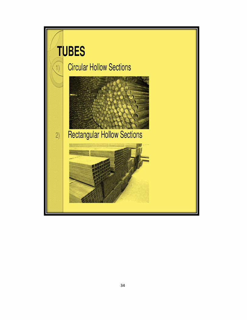
34

35
36

37

38
39

40
o

41
Double Hexagon Space Frames

42
43
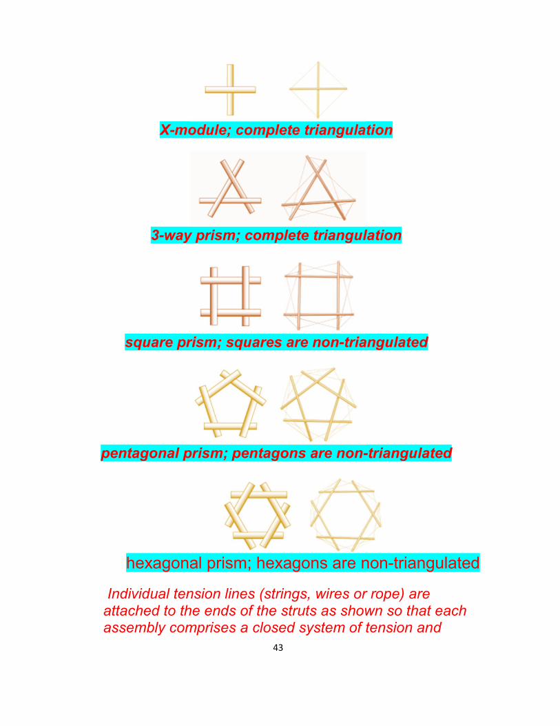
X-module; complete triangulation
3-way prism; complete triangulation
square prism; squares are non-triangulated
pentagonal prism; pentagons are non-triangulated
hexagonal prism; hexagons are non-triangulated
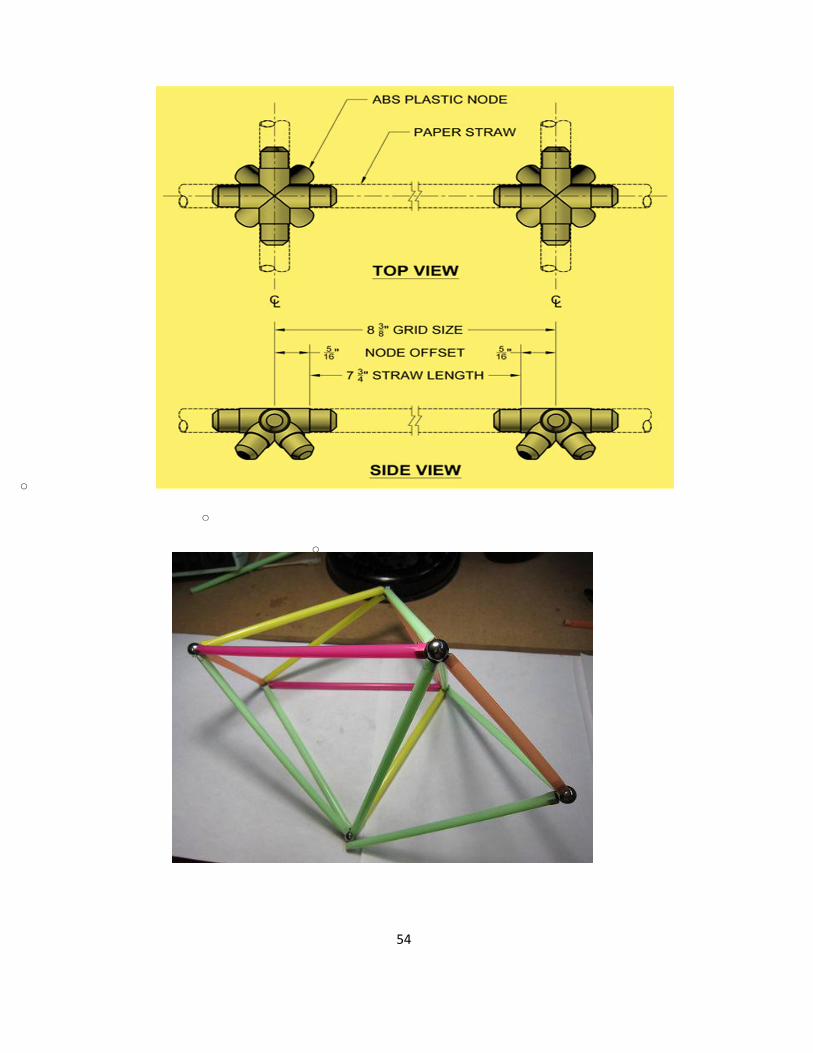
Individual tension lines (strings, wires or rope) are attached to the ends of the struts as shown so that each assembly comprises a closed system of tension and

44
compression parts. Each tension line connects individually to the ends of two struts; they do not thread through like strings of beads.
45

46
Modular Display Systems
Cultural Centre is one of many buildings that will be erected in
Azerbaijan this year, and it is one of several projects exhibiting
progressive design elements and cutting-edge engineering solutions.

47

48
Early in the design process, engineers performed a mathematically
based computer analysis. “It's good practice to do structural
calculations for projects of that kind with a 3D nonlinear finite element
analysis, including special loads like earthquake and high wind loads as
present in Baku, project engineer for the Heydar Aliyev Cultural
Centre. “We did the calculations with two separate full-model 3D finite
element programs, in order to compare the results and not to rely on a
single one.”
Curve space frame

49

50
Technology

51

52
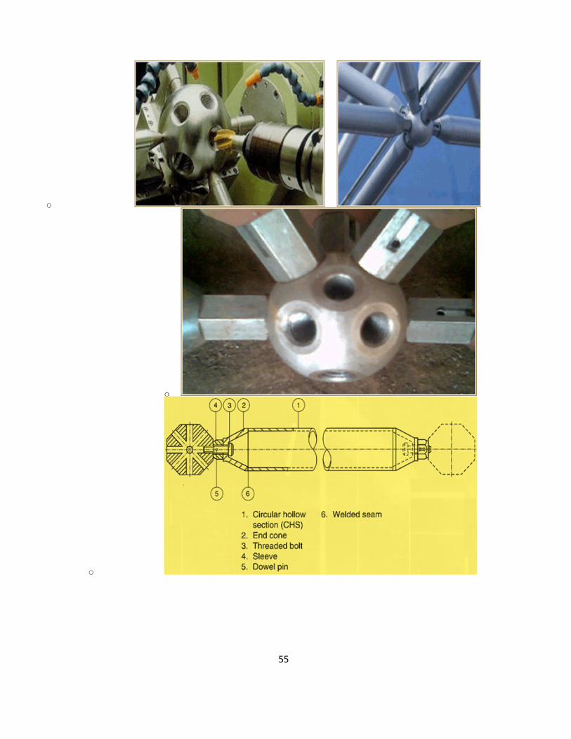
node connector of space frames
o

53
54
o
o
o
55
o
o
o

56
o
ADVANTAGES OF SPACE-FRAMES
Large spans can be achieved
Concentrated loads are evenly distributed on the entire structure
Pleasing decorative appearance
Fast installation at site due to pre-fabricated components
Very good acoustical properties
57
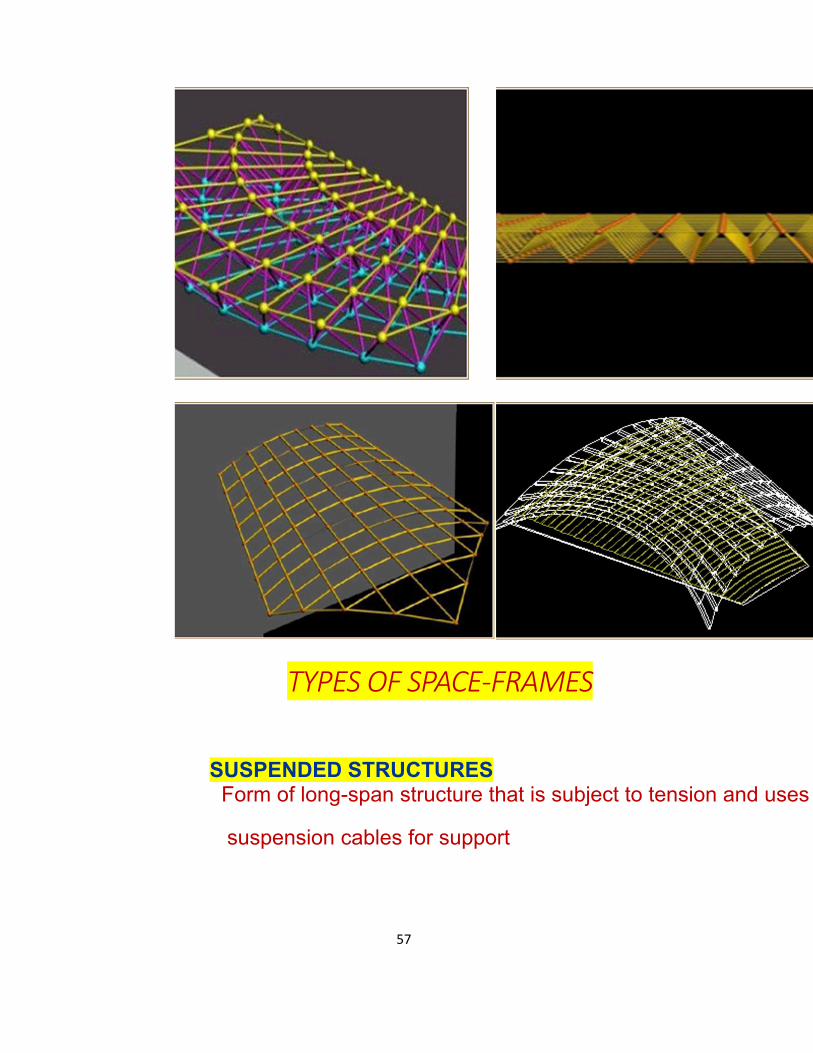
TYPES OF SPACE-FRAMES
SUSPENDED STRUCTURES Form of long-span structure that is subject to tension and uses
suspension cables for support

58
SKELETON FRAMEWORKS Number of bars interconnected at the nodes
STRESSED SKIN SYSTEMS
Using a composition of thin sheet material and ribs is a
total structural system called STRESSED

59

60
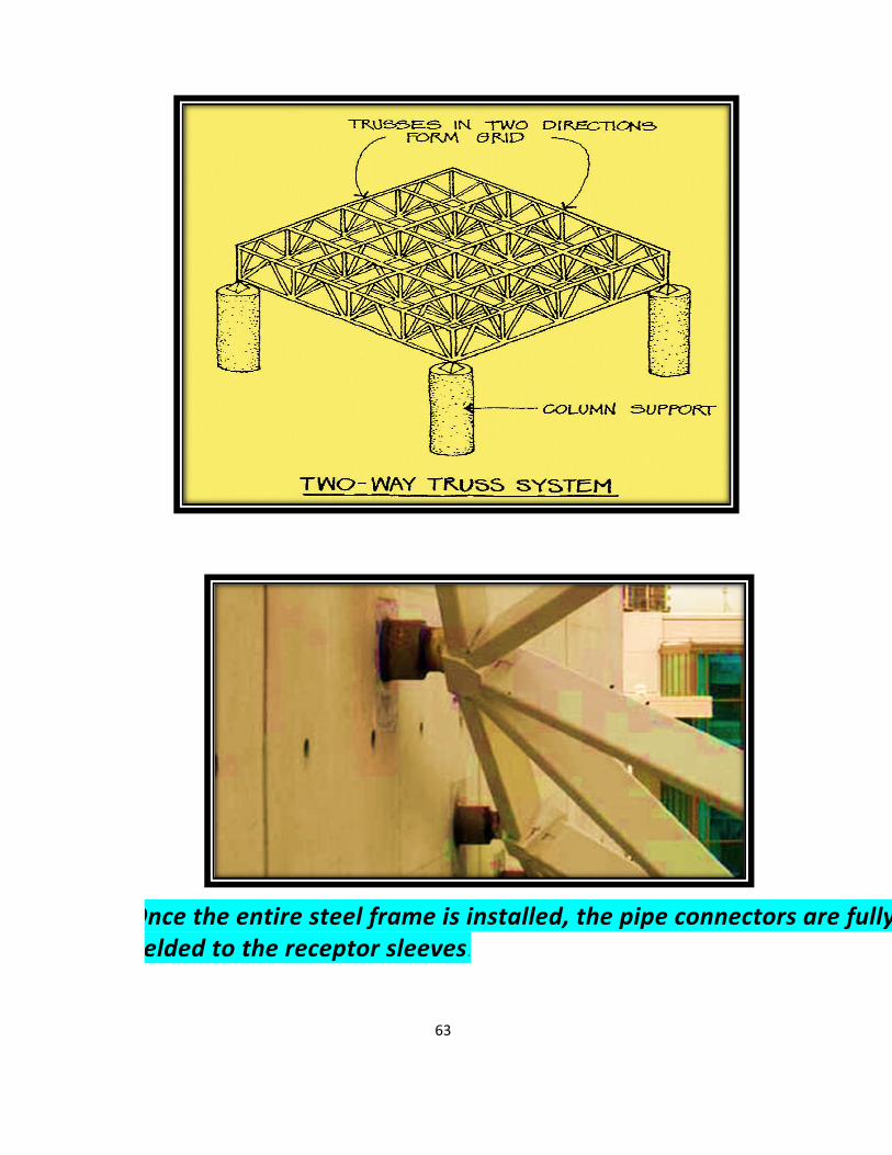
DOUBLE LAYER GRID
Of all the types of space-frames, the double layered grid structure is most popular because al its members are mainly under the action of axial forces,leading to the full utilization of all elements.
They are easily extendable
D ouble layered grids have a top frame , a bottom frame and inter-connecting
diagonal members
SPACFRAME
Members (Pipe connector) (Bolt, Collar, Bush end, MS pipe)

61
Space Frame Pyramid Structure

62
63
Once the entire steel frame is installed, the pipe connectors are fully welded to the receptor sleeves.

64
SuperStructure Systems

65

66
Space Frame & Skylight
In architecture and structural engineering, a space frame or space structure is a truss-like, lightweight rigid structure constructed from interlocking struts in a geometric pattern. Space frames can be used to

67
span large areas with few interior supports.

68

69
If a force is applied to the blue node, and the red bar is not present, the behaviour of the structure depends completely on the bending rigidity of the blue node. If the red bar is present, and the bending rigidity of the blue node is negligible compared to the contributing rigidity of the red bar, the system can be calculated using a rigidity matrix, neglecting angular factors.

70

71

72

73
Design Loads-Dead Load

74

75

76

77

78

79

80

81

82

83

84

85

86

87

88

89
System III Space Frame
The most versatile and attractive forged steel ball and tube system available. Exclusively ours.
Easiest ball and tube system to assemble.
Virtually unlimited span capability. Flexibility of form through freedom of angle.
Pyramid Sphere Space Frame
Traditional ball and tube appearance without the cost. Your space frame system of choice for beauty and economy.
Variable module designs.
Top junction plate for economical design.
Long span capability.
Direct decking or cladding attachment. Bottom junction ball design for aesthetic integrity.
Hemispherical Node
Our most economical space frame system. Fits most geometric designs.
Easiest, most economical system to assemble.
Variable module sizes.
Ideal solutions for medium spans.
Forged steel node-the most compact, high quality connector.
Axent Space Frame non-structural system
Attractive and cost efficient addition to any display
or exhibit. Practical assembly with the aid of a hand wrench only. Consists of pre-cut and in-stock material ready to ship.
90

91
92

93

94

95
96
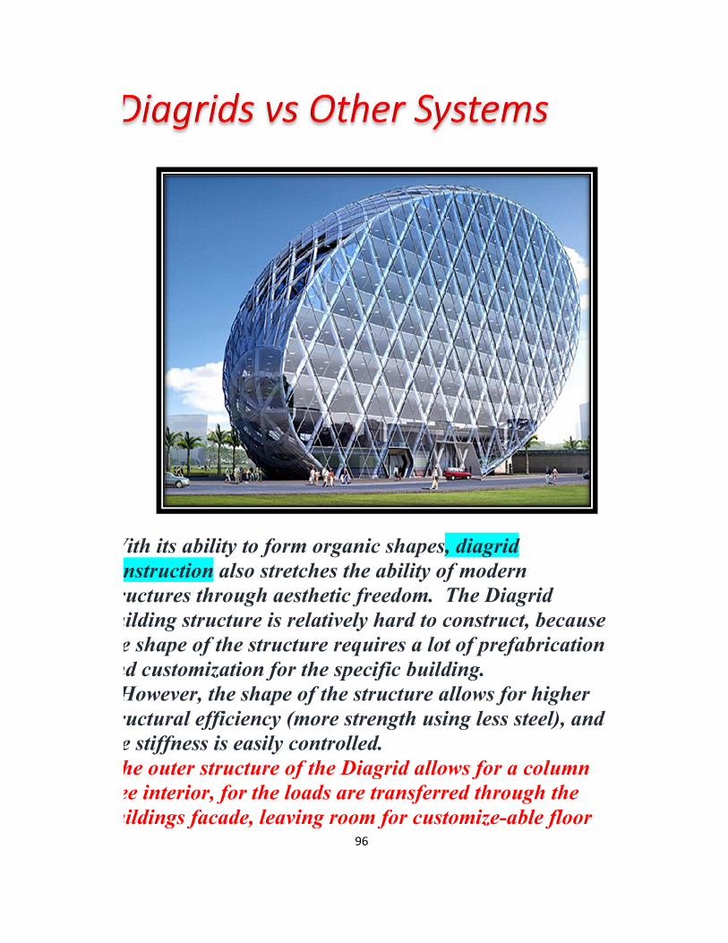
With its ability to form organic shapes, diagrid construction also stretches the ability of modern structures through aesthetic freedom. The Diagrid building structure is relatively hard to construct, because the shape of the structure requires a lot of prefabrication and customization for the specific building.
However, the shape of the structure allows for higher structural efficiency (more strength using less steel), and the stiffness is easily controlled. The outer structure of the Diagrid allows for a column free interior, for the loads are transferred through the buildings facade, leaving room for customize-able floor

97
plans. Compared to more traditional (concrete & steel) methods of sky scraper design, the diagrid allows for a lighter design, which contributes to a smaller foundation, making material costs lower in all aspects. Although, due to the complexity of the design, customized glass planels, and that the construction method is relatively new, all contribute in make the structure more expensive than traditional systems. Because of these aspect, Diagrids are generally used for high rise towers, and compete with normal concrete and steel designs.
Diagrid Structural System Materials and Limitations
Materials
98
Very often these structures are composed of steel members. However, they are not limited to steel and can be constructed of wood or reinforced
concrete as well. Although concrete is good in compression, and reinforcement helps with tensile and reinforcement helps with tensile loads, neither wood nor
concrete has the combination of tensile strength and compression strength that steel has. With a Modulus of Elasticity being 30,000 ksi, steel retains its shape under high loads very well making it ideal for this type of system. Reinforced concrete can be used to alter. The height to width ratio
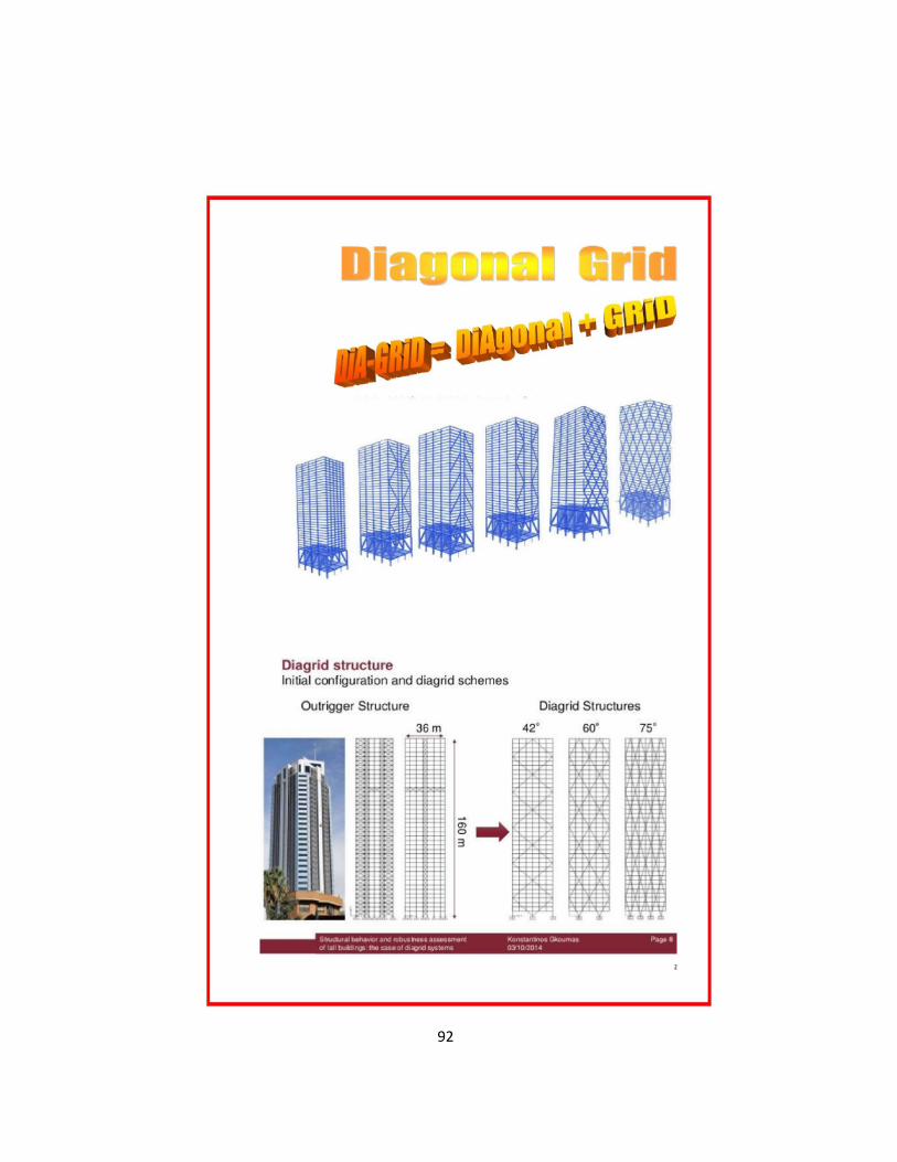
is typically from 6.0-8.7. For structures with a height to width ratio higher than a 7.0 (70 stories, 80 stories), it is more beneficial to use varying angles in the diagrid system (73, 69, 63 degrees). When a building's height to width ratio is lower than 7.0 (40, 50,
or 60 stories), it is more beneficial to use uniform angles throughout the system (69 degrees). The steeper angles at the lower levels increase bending rigidity while shallow angles increase shear rigidity. It is important for shorter buildings to have higher shear rigidity. It is also important for taller buildings to have higher bending
rigidity. .

99
Limitations
The Diagrid structural system allows for a more sturdy solution to building tall skyscrapers. Like all structural systems,

100
diagrids have limits too. For a diagrid system constructed of steel, the typical height limitation is 100 stories.
For a diagrid system constructed of concrete, the typical height limitation is lower at 60 stories. Both of these materials allow for extremely tall, structurally stable building systems.
Concrete diagrid systems require a large amount of form work which leads to higher construction costs.
The connection nodes that hold together all the joining members
are also very complex compared to typical orthogonal building systems. These connections are prefabricated and increase construction costs due to their complexity.
Skyscrapers
Owners of skyscrapers benefit from maximizing rentable space in their structures. For this reason, a Diagrid system is ideal because it can minimize the use of interior columns, thus maximizing interior space. In addition, diagrids form a

101
light and airy structure, which are desired for minimizing gravity and lateral loads
Load Distribution
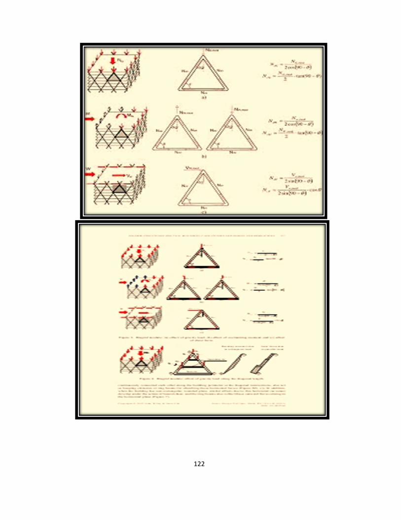
The load distribution in a Diagid is similar to that of a truss, where loads applied at the nodes are transferred by each each member through axial forces. However, unlike trusses where one basic assumption is that all loads are applied at nodes (thus eliminating shear forces), analysis of Diagrid systems include non-nodal loads, which induce shear forces. The following figure shows the load path in a Diagrid system
under a gravity point load. As evident from the figure, the nodal load is transmitted by the diagonal members, quickly dissipating the load.

102
Load Path in a Diagrid Under a Gravity Point Load Similar to this load distribution is that of a lateral point load
applied at a node. The diagonal members serves as a brace frame, which transmits the lateral loads axially to the ground. The following figure shows this load path.

103
Load Path in a Diagrid Where
Lateral Loads are Applied at the Nodes
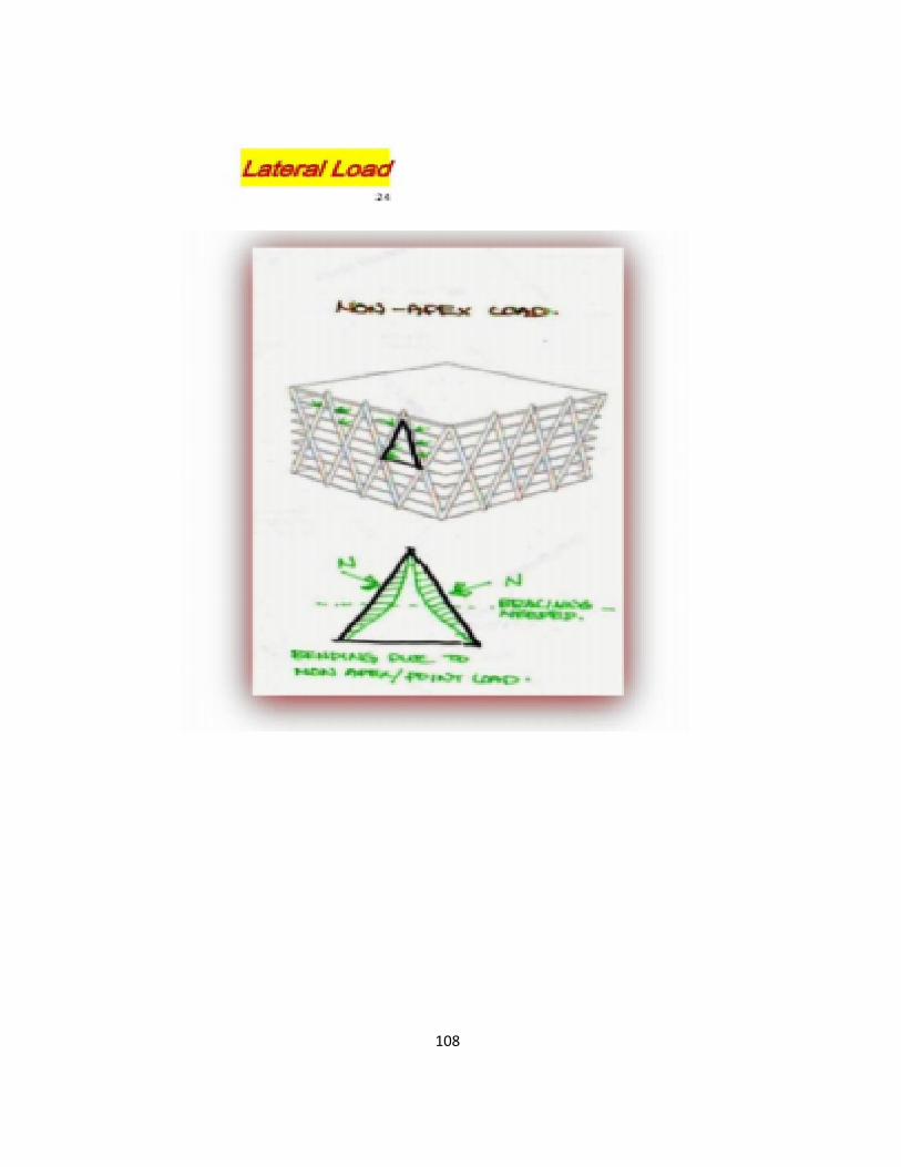
However, for the transmission of distributed loads or loads that are not applied at the nodes, horizontal members transfer loads to diagonal members through shear forces. The following figure shows how the loads are transmitted to the ground. The green lines show the transfer of loads by shear action, while the red lines show transfer through axial action.

104
Load Path in a Diagrid System Under Distributed Gravity Loads
The load paths shown verifies the ability of a Diagrid system to provide both lateral and gravity support in one system. The diagonals, as stated earlier, provides a quicker way of transferring loads to the ground through axial forces, while horizontal may transfer forces axially or by shear, depending on the type of loading applied.
Compared to conventional framing, Diagrid systems have a wider spread of loads, and lesser contact with ground (as it has lesser members), which may affect the selection of its foundation system. Depending on the foundation system chosen, Diagrids may require lesser support. For instance, for a

105
deep foundation, Diagrids may require less piles, since there is less members and concentrated loads

106

107
108

109

110

111

112

113

114
115

116

117

118

119

120
121
122

123

124

125

126
127

128

129

130