004. radio structure.pdf
TRANSCRIPT

FlexiPacket MultiRadio Structure
FT48926EN03GLA0
© 2012 Nokia Siemens Networks 1
Content
1 FlexiPacket MultiRadio description 3
1.1 FlexiPacket MultiRadio Block Diagram 3
2 FlexiPacket MultiRadio Mechanical Structure and Radio Flanges 9
2.1 FPMR Mechanical Structure and Radio Flanges 10
2.2 FlexiPacket MultiRadio Antenna Interface 13
2.3 FlexiPacket MultiRadio External Connections 15
3 Alternative Connections to an Indoor Device 19
3.1 Introduction 19
FlexiPacket MultiRadio Structure
FlexiPacket MultiRadio Structure
FT48926EN03GLA0
© 2012 Nokia Siemens Networks 9
2 FlexiPacket MultiRadio Mechanical Structure and Radio Flanges
FlexiPacket MultiRadio Structure
FT48926EN03GLA0
© 2012 Nokia Siemens Networks 10
2.1 FPMR Mechanical Structure and Radio Flanges
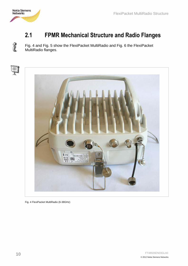
Fig. 4 and Fig. 5 show the FlexiPacket MultiRadio and Fig. 6 the FlexiPacket MultiRadio flanges.
Fig. 4 FlexiPacket MultiRadio (6-38GHz)

FlexiPacket MultiRadio Structure
FT48926EN03GLA0
© 2012 Nokia Siemens Networks 11
. . . . . . . . . . . . . . . . . . . . . . . . . . . . . . . . . . . . . . . . . . . . . . . . . . . . . . . . . . . . . . . . . . . . . . . . . . . . . . . . . . . . . . . . . . . . . . . . . . . . . . . . . . . . . . . . . . . . . . . . . . . . . . . . . . . . . . . . . . . . . . . . . . . . . . . . . . . . . . . . . . . . . . . . . . . . . . . . . . . . . . . . . . . . . . . . . . . . . . . . . . . . . . . . . . . . . . . . . . . . . . . . . . . . . . . . . . . . . . . . . . . . . . . . . . . . . . . . . . . . . . . . . . . . . . . . . . . . . . . . . . . . . . . . . . . . . . . . . . . . . . . . . . . . . . . . . . . . . . . . . . . . . . . . . . . . . . . . . . . . . . . . . . . . . . . . . . . . . . . . . . . . . . . . . . . . . . . . . . . . . . . . . . . . . . . . . . . . . . . . . . . . . . . . . . . . . . . . . . . . . . . . . . . . . . . . . . . . . . . . . . . . . . . . . . . . . . . . . . . . . . . . . . . . . . . . . . . . . . . . . . . . . . . . . . . . . . . . . . . . . . . . . . . . . . . . . . . . . . . . . . . . . . . . . . . . . . . . . . . . . . . . . . . . . . . . . . . . . . . . . . . . . . . . . . . . . . . . . . . . . . . . . . . . . . . . . . . . . . . . . . . . . . . . . . . . . . . . . . . . . . . . . . . . . . . . . . . . . . . . . . . . . . . . . . . . . . . . . . . . . . . . . . . . . . . . . . . . . . . . . . . . . . . . . . . . . . . . . . . .
© Nokia Siemens Networks
Fig. 5 FlexiPacket MultiRadio Radio (3.5GHz)

FlexiPacket MultiRadio Structure
FT48926EN03GLA0
© 2012 Nokia Siemens Networks 15
2.3 FlexiPacket MultiRadio External Connections
FlexiPacket Radio is provided with five connectors (Fig. 8):
Ethernet Connector
Power Supply Connector
AGC Connector
ODU-ODU connector
Grounding Point
Fig. 8 FlexiPacket MultiRadio External Connections

FlexiPacket MultiRadio Structure
FT48926EN03GLA0
© 2012 Nokia Siemens Networks 16
Ethernet connector
The Ethernet connector is used to connect an Indoor Device and the FlexiPacket MultiRadio.
The Ethernet connector supports the Power + Ethernet (P+E): its function is of carrying both power and data over the same cable.
The data interface is a 10/100/1000Base-T (GbE), while power interface is based on enhanced “Power+Ethernet”.
The Ethernet connector is a shielded Amphenol multi-polar connector with 8 golden power pins. Each pin can accept at least 22 to 24 AWG wire diameter.
The Ethernet cable is a double shielded four twisted pairs Cat 5e cable. A 24-valued AWG (min.) is necessary to minimize cable power loss. Cable materials are designed to meet outdoor conditions. The cable shield shall be connected to the FlexiPacket MultiRadio grounding point.
PS connector
This connector is used to power supply the FlexiPacket MultiRadio with a dedicated power supply (-48 Vdc + 20%) cable. In this case the interconnection with an Indoor Device is implemented with 2 cables.
The PS connector is a shielded Amphenol multipolar connector with 2 golden power pins. Each pin can accept at least 13 AWG wire diameter.
The PS cable is a shielded, two wire cable. A 13-valued AWG (min.) is necessary to minimize cable power loss; with this value 200m connection is guaranteed over the temperature range -40° to +60°C. Cable materials shall be designed to meet outdoor conditions.
The cable shield must be connected to the FlexiPacket MultiRadio grounding point.

FlexiPacket MultiRadio Structure
FT48926EN03GLA0
© 2012 Nokia Siemens Networks 17
AGC connector (RSSI)
The RSSI interface allows measuring the received RF signal level with a standard voltmeter through a female BNC 50 ohm, IP65 waterproof connector.
The table below reports the RSSI parameters.
Fig. 9 RSSI parameters
ODU-ODU connector
This connector must be used to connect the ODU-ODU cable to the second FlexiPacket MultiRadio in the configurations with two FlexiPacket MultiRadios.
The connector is a proprietary multicoaxial connector.
WARNING Detailed information about Connectors is reported on the Installation and Commissioning manual FT4889
.

FlexiPacket MultiRadio Structure
FT48926EN03GLA0
© 2012 Nokia Siemens Networks 20
3.1.1 Alternative (a)
The connection distance is shorter than 100m (Ethernet standard upper limit) and the Generic Indoor Device has its own P+E interface. The Power Supply Unit (PSU) provides the power directly to the Generic Indoor Device. The latter converts it into an appropriate DC voltage, which will be delivered over the Ethernet cable together with GbE data interface according to P+E specifications.
Generic IDU
PSU
P+E ≤ 100 mt
FlexiPacket
ODU
PS
Fig. 10 Alternative (a)

FlexiPacket MultiRadio Structure
FT48926EN03GLA0
© 2012 Nokia Siemens Networks 21
. . . . . . . . . . . . . . . . . . . . . . . . . . . . . . . . . . . . . . . . . . . . . . . . . . . . . . . . . . . . . . . . . . . . . . . . . . . . . . . . . . . . . . . . . . . . . . . . . . . . . . . . . . . . . . . . . . . . . . . . . . . . . . . . . . . . . . . . . . . . . . . . . . . . . . . . . . . . . . . . . . . . . . . . . . . . . . . . . . . . . . . . . . . . . . . . . . . . . . . . . . . . . . . . . . . . . . . . . . . . . . . . . . . . . . . . . . . . . . . . . . . . . . . . . . . . . . . . . . . . . . . . . . . . . . . . . . . . . . . . . . . . . . . . . . . . . . . . . . . . . . . . . . . . . . . . . . . . . . . . . . . . . . . . . . . . . . . . . . . . . . . . . . . . . . . . . . . . . . . . . . . . . . . . . . . . . . . . . . . . . . . . . . . . . . . . . . . . . . . . . . . . . . . . . . . . . . . . . . . . . . . . . . . . . . . . . . . . . . . . . . . . . . . . . . . . . . . . . . . . . . . . . . . . . . . . . . . . . . . . . . . . . . . . . . . . . . . . . . . . . . . . . . . . . . . . . . . . . . . . . . . . . . . . . . . . . . . . . . . . . . . . . . . . . . . . . . . . . . . . . . . . . . . . . . . . . . . . . . . . . . . . . . . . . . . . . . . . . . . . . . . . . . . . . . . . . . . . . . . . . . . . . . . . . . . . . . . . . . . . . . . . . . . . . . . . . . . . . . . . . . . . . . . . . . . . . . . . . . . . . . . . . . . . . . . . . . . . . . . . . . . . . . . . . . . . . . . . . . . . . . . . . . . . . . . . . . . . . . . . . . . . . . . . . . . . . . . . . . . . . . . . . . . . . . . . . . . . . . . . . . . . . . . . . . . . . . . . . . . . . . . . . . . . . . . . . . . . . . . . . . . . . . . . . . . . . . . . . . . . . . . . . . . . . . . . . . . . . . . . . . . . . . . . . . . . . . . . . . . . . . . . . . . . . . . . . . . . . . . . . . . . . . . . . .
ODU – Indoor Cabling Scenario
Alternative a
-48V DC
DC Power
Distribution
Switch or
other Device
with Eth I/O
Eth and P+E
Fig. 11 Alternative (a)

FlexiPacket MultiRadio Structure
FT48926EN03GLA0
© 2012 Nokia Siemens Networks 22
3.1.2 Alternative (b)
Connection distance is shorter than 100m (Ethernet standard upper limit) and the Generic Indoor Device has not its own P+E interface.
Generic IDU
PSU
≤ 100 mt
FlexiPacket
ODUPS
PS
GbE
Fig. 12 Alternative (b)

FlexiPacket MultiRadio Structure
FT48926EN03GLA0
© 2012 Nokia Siemens Networks 23
. . . . . . . . . . . . . . . . . . . . . . . . . . . . . . . . . . . . . . . . . . . . . . . . . . . . . . . . . . . . . . . . . . . . . . . . . . . . . . . . . . . . . . . . . . . . . . . . . . . . . . . . . . . . . . . . . . . . . . . . . . . . . . . . . . . . . . . . . . . . . . . . . . . . . . . . . . . . . . . . . . . . . . . . . . . . . . . . . . . . . . . . . . . . . . . . . . . . . . . . . . . . . . . . . . . . . . . . . . . . . . . . . . . . . . . . . . . . . . . . . . . . . . . . . . . . . . . . . . . . . . . . . . . . . . . . . . . . . . . . . . . . . . . . . . . . . . . . . . . . . . . . . . . . . . . . . . . . . . . . . . . . . . . . . . . . . . . . . . . . . . . . . . . . . . . . . . . . . . . . . . . . . . . . . . . . . . . . . . . . . . . . . . . . . . . . . . . . . . . . . . . . . . . . . . . . . . . . . . . . . . . . . . . . . . . . . . . . . . . . . . . . . . . . . . . . . . . . . . . . . . . . . . . . . . . . . . . . . . . . . . . . . . . . . . . . . . . . . . . . . . . . . . . . . . . . . . . . . . . . . . . . . . . . . . . . . . . . . . . . . . . . . . . . . . . . . . . . . . . . . . . . . . . . . . . . . . . . . . . . . . . . . . . . . . . . . . . . . . . . . . . . . . . . . . . . . . . . . . . . . . . . . . . . . . . . . . . . . . . . . . . . . . . . . . . . . . . . . . . . . . . . . . . . . . . . . . . . . . . . . . . . . . . . . . . . . . . . . . . . . . . . . . . . . . . . . . . . . . . . . . . . . . . . . . . . . . . . . . . . . . . . . . . . . . . . . . . . . . . . . . . . . . . . . . . . . . . . . . . . . . . . . . . . . . . . . . . . . . . . . . . . . . . . . . . . . . . . . . . . . . . . . . . . . . . . . . . . . . . . . . . . . . . . . . . . . . . . . . . . . . . . . . . . . . . . . . . . . . . . . . . . . . . . . . . . . . . . . . . . . . . . . . . . . . . . . . . . . . . . . . . . . . . . . . . . . . . . . . . . . . . . .
ODU – Indoor Cabling Scenario
Alternative b
Eth -48V DC
DC Power
Distribution
Switch or
other Device
with Eth I/O
Fig. 13 Alternative (b)

FlexiPacket MultiRadio Structure
FT48926EN03GLA0
© 2012 Nokia Siemens Networks 24
3.1.3 Alternative (c)
Connection distance is shorter than 100m (Ethernet standard upper limit) and the Generic Indoor Device has not its own P+E interface.
If the single cable between the Generic Indoor Device and the FlexiPacket ODU is a must, a Power injector device is used to insert power onto an Ethernet cable (see Fig. 15).
FlexiPacket ODU catalogue foresees 2 Power Injector items:
4 ports Power Injector for indoor application (Fig. 16)
1 port Power Injector for outdoor application (Fig. 17)
Generic IDU
PSU
P+E ≤ 100 mt
FlexiPacket
ODU
Power
Injector
GbE
PS
PS
Fig. 14 Alternative (c)
WARNING The following IDUs do not support the P+E:
FlexiPacket Hub 2200 and
FlexiPacket Hub1200
Flexi BTS Transport Cards FTIB, FTLB, FTFB, AXCF
FlexiPacket FirstMile 200 has two Ethernet ports with embedded power (P+E) to FlexiPacket ODU.

FlexiPacket MultiRadio Structure
FT48926EN03GLA0
© 2012 Nokia Siemens Networks 25
Fig. 15 Power Injector reference network
Four in/out Ports (IDU Cable/ODU Cable) 5 Dry Contacts:
4 Data port short Circuit Alarm
1 Short Circuit Combination
Alarm
Redundant
DC Input
Power injector indoor supporting up to 4 ODUs
Fig. 16 Power Injector (Indoor 4 ports)

FlexiPacket MultiRadio Structure
FT48926EN03GLA0
© 2012 Nokia Siemens Networks 26
Outdoor Power Injector
• Monolithic outdoor architecture IP55
• Environment compliant to ETSI Class 4.1
extended range (-40°C ÷ +55°C)
• 3 ports: DC input, 10/100/1000BaseT on RJ45
interface, 10/100/1000 BaseT + direct -48VDC
outputs on RJ45 interface
• DC input -48VDC ± 20%
• Power output >60 W
• Sourge protection on output port (5kV)
• MTBF >400 Kh (theoretical, 25°C, maximum
load)
• Power injector for outdoor installation supporting one FP ODU
Fig. 17 Outdoor Power Injector

FlexiPacket MultiRadio Structure
FT48926EN03GLA0
© 2012 Nokia Siemens Networks 27
© Nokia Siemens Networks
Fig. 18
Example of site (zero footprint)
FlexiPacket Radio and power injector
Transport
sub-modulea
Power
Supplyi
AB
b
Outdoor
Power
Injector
d
jD -48Vdc
System Module
FlexiPacket ODU
FlexiWCDMA
Power
module
RF module
RF module
Length <100m
Ethernet Ethernet and 48V
Fig. 19 Zero footprint

FlexiPacket MultiRadio Structure
FT48926EN03GLA0
© 2012 Nokia Siemens Networks 28
The Indoor Power Injector has a standard RJ45 connector on the front panel for Alarms reporting (Fig. 20.
© Nokia Siemens Networks
Fig. 20 ALMs connector front view
Refer to Fig. 21 for the relevant pinout map.
© Nokia Siemens Networks
Fig. 21 ALMs connector pin function
Alarms are reported according to the following rule:
Normal state (no alarm): relevant pair of pins (i.e. pin1-pin2 for short circuit on ODU1 power supply) are open and both floating respect to ground
Alarm active: relevant pair of pins (i.e. pin1-pin2 for short circuit on ODU1 power supply) are shortened each other by internal MOS device; both pins are floating respect to ground
All alarm lines support both positive and negative external bias
Wired OR of multiple alarms can be easily done.

FlexiPacket MultiRadio Structure
FT48926EN03GLA0
© 2012 Nokia Siemens Networks 29
3.1.4 Alternative (d)
Connection distance is longer than 100m.
In this case a Repeater device is used to extend the Ethernet standard limit up to 200m.
The repeater device also forwards the Power Supply.
Generic IDU
PSU
GbE ≤ 100 mt
FlexiPacket
ODU
Repeater
GbE
PS
GbE ≤ 100 mt
PS
PS
GbE
Fig. 22 Alternative (d)

FlexiPacket MultiRadio Structure
FT48926EN03GLA0
© 2012 Nokia Siemens Networks 30
3.1.5 Alternative (e)
Connection distance is longer than 200m.
In this scenario two repeaters are used to cover distances between the Generic Indoor Device and the FlexiPacket ODU of up to 300m.
Generic IDU
PSU
GbE ≤ 100 mt
FlexiPacket
ODU
Repeater
GbE
PS
GbE ≤ 100 mt
PS
PS
GbERepeater
Gb
E
PS
Gb
E≤
10
0 m
t
Fig. 23 Alternative (e)

FlexiPacket MultiRadio Structure
FT48926EN03GLA0
© 2012 Nokia Siemens Networks 31
. . . . . . . . . . . . . . . . . . . . . . . . . . . . . . . . . . . . . . . . . . . . . . . . . . . . . . . . . . . . . . . . . . . . . . . . . . . . . . . . . . . . . . . . . . . . . . . . . . . . . . . . . . . . . . . . . . . . . . . . . . . . . . . . . . . . . . . . . . . . . . . . . . . . . . . . . . . . . . . . . . . . . . . . . . . . . . . . . . . . . . . . . . . . . . . . . . . . . . . . . . . . . . . . . . . . . . . . . . . . . . . . . . . . . . . . . . . . . . . . . . . . . . . . . . . . . . . . . . . . . . . . . . . . . . . . . . . . . . . . . . . . . . . . . . . . . . . . . . . . . . . . . . . . . . . . . . . . . . . . . . . . . . . . . . . . . . . . . . . . . . . . . . . . . . . . . . . . . . . . . . . . . . . . . . . . . . . . . . . . . . . . . . . . . . . . . . . . . . . . . . . . . . . . . . . . . . . . . . . . . . . . . . . . . . . . . . . . . . . . . . . . . . . . . . . . . . . . . . . . . . . . . . . . . . . . . . . . . . . . . . . . . . . . . . . . . . . . . . . . . . . . . . . . . . . . . . . . . . . . . . . . . . . . . . . . . . . . . . . . . . . . . . . . . . . . . . . . . . . . . . . . . . . . . . . . . . . . . . . . . . . . . . . . . . . . . . . . . . . . . . . . . . . . . . . . . . . . . . . . . . . . . . . . . . . . . . . . . . . . . . . . . . . . . . . . . . . . . . . . . . . . . . . . . . . . . . . . . . . . . . . . . . . . . . . . . . . . . . . . . . . . . . . . . . . . . . . . . . . . . . . . . . . . . . . . . . . . . . . . . . . . . . . . . . . . . . . . . . . . . . . . . . . . . . . . . . . . . . . . . . . . . . . . . . . . . . . . . . . . . . . . . . . . . . . . . . . . . . . . . . . . . . . . . . . . . . . . . . . . . . . . . . . . . . . . . . . . . . . . . . . . . . . . . . . . . . . . . . . . . . . . . . . . . . . . . . . . . . . . . . . . . . . . . . . . . . . . . . . . . . . . . . . . . . . . . . . . . . . . . . . . . . . . . . . . . . . . . . . . . . . . . . . . . . . . . . . . . . . . . . . . . . . . . . . . . . . . . . . . . . . . . . . . . . . . . . . . . . . . . . . . . . . . . . . . . . . . . . . . . . . . . . . . . . . . . . . . . . . . . . . . . . . . . . . . . . . . . . . . . . . . . . . . . . . . . . . . . . . . . . . . . . . . . . . . . . . . . . . .
Eth-LAN vs
Indoor device
(i.e. Switch)
Eth
DC PSU Cable vs Power
distribution and PSU DC
Voltage source
-48V DC
Eth
Repeater
-48V DC
Eth
In/Out DC Cables
In/Out EthCables
Repeater - Outdoor
Max 100 mt
Possibility to use up to 2 Lan Repeater for total
length close to 300 mt
Max 100 mt
Fig. 24 Alternative (d) and (e)

FlexiPacket MultiRadio Structure
FT48926EN03GLA0
© 2012 Nokia Siemens Networks 32
3.1.5.1 Repeater
The Repeater is a device capable of extending the Ethernet connection length over the standard limit.
This is necessary when the distance between the Indoor Device and the FlexiPacket ODU is longer than 100m.
It is designed for outdoor environment.
The device manages a single Indoor Device-FlexiPacket ODU connection: in protected configurations, two repeaters are needed to handle two Indoor- Outdoor links (i.e., one repeater for each FlexiPacket ODU).
© Nokia Siemens Networks
Fig. 25 Ethernet Repeater