01-08 (en) - kenwoodmanual.kenwood.com/files/b60-4707-00.pdf · 2010-09-17 · sound. 5-disc...
TRANSCRIPT

PlayerB60-4707-00 00 CS (T,K,M,X) AP @0004
DV-4900 DV-4070DVF-R9030 DVF-R7030
Multiple DVD VCD CD
TEXTTEXTDIGITAL AUDIO
COMPACT
DIGITAL VIDEODIGITAL VIDEO
COMPACT
This instruction manual is used todescribe multiple models listed above.Model availability and features(functions) may differ depending on thecountry and sales area.

2
Before applying powerUnits are designed for operation as follows.
U.S.A. and Canada.................................AC 120 V
Australia ......................................... AC 110-240 V
Europe and U.K. ................................... AC 230 V
Other countries .............................. AC 110-240 V
For the United Kingdom
Factory fitted moulded mains plug
1. The mains plug contains a fuse. For replacement, use only a 13-Amp ASTA-approved (BS1362) fuse.
2. The fuse cover must be refitted when replacing the fuse in the moulded plug.
3. Do not cut off the mains plug from this equipment. If the plug fitted is not suitable for the power pointsin your home or the cable is too short to reach a power point, then obtain an appropriate safety approvedextension lead or adapter, or consult your dealer.
If nonetheless the mains plug is cut off, remove the fuse and dispose of the plug immediately, to avoid apossible shock hazard by inadvertent connection to the mains supply.
IMPORTANT : The wires in the mains lead are coloured in accordance with the following code:
Blue : Neutral Brown : Live
Do not connect those leads to the earth terminal of a three-pin plug.
CLASS 1LASER PRODUCT
The marking of products using lasers(Except for some areas)
Safety precautions
WARNING : TO PREVENT FIRE OR ELECTRIC SHOCK, DO NOT EXPOSETHIS APPLIANCE TO RAIN OR MOISTURE.
CAUTION: TO REDUCE THE RISK OF ELECTRIC SHOCK,DO NOT REMOVE COVER (OR BACK). NO USER-SERVICEABLE PARTS INSIDE. REFER SERVICING TOQUALIFIED SERVICE PERSONNEL.
RISK OF ELECTRIC SHOCK
DO NOT OPEN
THE LIGHTNING FLASH WITH ARROWHEAD SYMBOL, WITHIN ANEQUILATERAL TRIANGLE, IS INTENDED TO ALERT THE USER TO THEPRESENCE OF UNINSULATED “DANGEROUS VOLTAGE” WITHIN THEPRODUCT’S ENCLOSURE THAT MAY BE OF SUFFICIENT MAGNITUDETO CONSTITUTE A RISK OF ELECTRIC SHOCK TO PERSONS.
THE EXCLAMATION POINT WITHIN AN EQUILATERAL TRIANGLE ISINTENDED TO ALERT THE USER TO THE PRESENCE OF IMPORTANTOPERATING AND MAINTENANCE (SERVICING) INSTRUCTIONS IN THELITERATURE ACCOMPANYING THE APPLIANCE.
CAUTION
CAUTIONINVISIBLE LASER RADIATIONWHEN OPEN AVOID EXPOSURETO BEAM
The marking is located on the rear panel and saysthis product has been classified as Class 1. It meansthat there is no danger of hazardous radiationoutside the product.
Inside this laser product, a laser diode classified asClass 2 laser radiation is contained as alerted by theinternal caution label shown above. To avoidexposure to laser beams, do not open the cover.
Caution : Read this page carefully to ensure safe operation.

3
AccessoriesJoystick remote control
unit (1)Batteries (R6/AA)
(2)S Video cable
(1)Video cable
(1)
Audio cables(3)
Optical fiber cable(1)
FeaturesCompatible with DVD AUDIO, one of the latestdigital audio formats
The DVD AUDIO reproduces 2-channel, 192kHz, 24-bit sampled digital audio or 6-channel,96 kHz, 24-bit sampled audio. This innovativetechnology has made possible audioreproduction in unprecedented high quality.Picture information and character information(ALBUM TEXT) are also provided.
Versatile DVD VIDEO Functions
The DVD VIDEO provides horizontal resolutionof 430 lines, which exceeds that of DVD or SVHS video (400 lines) or laserdisc (430 lines).The difference is obvious when the screen size isincreased.
Multi-audio function: With DVD discs markedwith the 8 icon, the desired language can beplayed back by selecting it from up to 8languages. (The number of available languagesis variable depending on the discs.)
Multi-subtitle function: With DVD discsmarked with the 32 icon, the subtitle languagecan be selected from up to 32 languages. (Thenumber of subtitle languages is variabledepending on the discs.)
Angle function: With DVD discs marked withthe 9 icon, a single object can be viewed inup to 9 angles by switching. (The number ofavailable angles is variable depending on thediscs.)
Compatibility with Wide Range of DigitalSurround Software
The unit incorporates Dolby Digital decoder,DTS decoder, MPEG multi-channel decoder andPacked PCM decoder so that the users can enjoythe sound of real cinemas. The unit can also beconnected to the user's existing TV set
6-Channel Output Terminals
These output terminals can be connected to anamplifier with 6-channel input compatibility toenjoy high-bit, high-sampling rate multi-channelsound.
5-Disc Carousel Disc Changer
The disc tray can accommodate up to 5 discs andthe disc can be changed while another disc isbeing played.
AC plug adapter (1)
Use to adapt the plug
on the power cord to
the shape of the wall
outlet. (Accessory only
for regions where use is
necessary.)
UnpackingUnpack the unit carefully and make sure that all accessoriesare put aside so they will not be lost.
Examine the unit for any possibility of shipping damage. Ifyour unit is damaged or fails to operate, notify your dealerimmediately. If your unit was shipped to you directly, notifythe shipping company without delay. Only the consignee (theperson or company receiving the unit) can file a claim againstthe carrier for shipping damage.
We recommend that you retain the original carton andpacking materials for use should you transport or ship theunit in the future.
Keep this manual handy for future reference.M u l t i p l e D V D V C D C D
Instructoin manual/separate User's Guide (1)

4
Contents Caution : Read the pages marked carefully to ensure safe operation.
Before applying power ................... 2
Safety precautions ................................... 2
Features .......................................................... 3Accessories ..................................................... 3Systems and Types of Playable Discs ............. 5
Unplayable Discs ............................................ 5Icons Inscribed on DVD Discs ....................... 6Region Codes of This Player (DVD VIDEO disconly) ............................................................... 6
Region codes of the DVD VIDEO discs that can beplayed with this player ..............................................7
Region codes in the world ....................................... 7
Video Formats ................................................ 8Checking the Video Format ..................................... 8
Chapter 1: Connection of Equipment ... 9
Connection with a TV or Stereo System ....... 10To Connect a TV ...................................................... 11
To Connect a Stereo System ................................... 11
To Set Up of the Player ........................................... 11
Connection with an AV Amplifier ................. 12To Connect an AV Amplifier .................................. 13
To Setup of the Player ............................................ 13
Chapter 2: Various Setups .................. 14Preparation of Remote Control Unit ........... 14
Installing the batteries : ......................................... 14
Remote control range : ........................................... 14
Turning Power on ........................................ 14Standby mode: ........................................................ 14
Control Buttons Used in Setups .................. 15Basic Operations in Setup Screen ................ 15
When "MAIN" is selected in "SET UP MENU": ... 16
When "SOUND" is selected in "SET UP MENU": 16
When "VISUAL" is selected in "SET UP MENU": 17
"MAIN" Setting ............................................. 18"Rating" Setting ...................................................... 18
"TV Aspect" Setting ................................................ 20
"TV Mode" Setting ................................................. 20
"TV Monitor Type" Setting .................................... 21
"DVD VIDEO Mode" Setting ................................. 22
"OSD Position" Setting .......................................... 22
"On Screen Message" Setting ................................ 23
"IPB Display" Setting ............................................. 24
"SOUND" Setting.......................................... 26"Digital Audio PCM Down Conversion"
Setting .................................................................. 26
"Digital Audio Dolby Digital" Setting .................. 26
"Digital Audio DTS" Setting .................................. 27
"Digital Audio MPEG" Setting .............................. 28
"Speaker Setting" .................................................... 28
"Audio During Search" Setting ............................. 32
"Dynamic Range Control" Setting ........................ 32
"Audio Filter" Setting ............................................ 33
"VISUAL" Setting .......................................... 34"Player Menu Language" Setting ........................... 34
"Disc Menu Language" Setting .............................. 34
"Audio Language" Setting ...................................... 35
"Subtitle Language" Setting ................................... 36
"Still Mode" Setting ............................................... 36
"FL Mode" Setting .................................................. 37
"NTSC = PAL" Setting (Except for the U.S.A. andCanada) ................................................................... 38
"SCART Output Select" Setting (For Europe and U.K.)............................................................................. 38
Disc Language Code Table ..................................... 40
Chapter 3: Other Information ............ 41To Be Noted .................................................. 41Glossary........................................................ 43Index ............................................................ 45Specifications ............................................... 46
As an ENERGY STAR® Partner,Kenwood Corporation has determinedthat this products meets the ENERGY
STAR® guidelines for energy efficiency.
This product can save energy. Saving energy reducesair pollution and lowers utility bills.

5
Unplayable DiscsNever attempt to play a Photo CD, CD-R or CD-RW disc on this unit. Otherwise, the disc data maybe destroyed.
Other discs which cannot be played on this unit:
¶ SACD, DVD-ROM, DVD-R/RAM, DVD-RW, CD-ROM, VSD, CDV*, CD-G*, CD-EG*, CD-EXTRA*, etc.* Only the audio part can be reproduced.
¶ A DVD VIDEO disc with a region code whichdoes not match this unit or without a regioncode. For details, see "Region Codes of ThisPlayer". 6
¶ When the video format of a disc differs from thatof the TV in use, the disc cannot be playednormally. For details, see "Video Formats".
8
12 cm or 8 cm
Playable Disc
Disc size
Played side(s)
TEXTDIGITAL AUDIO
COMPACT
1 or 2
DVD AUDIO DVD VIDEO CDVCD
1 or 2 1 side only 1 side only
Logo mark
12 cm or 8 cm
DIGITAL AUDIO
COMPACT
DIGITAL VIDEO
COMPACT
12 cm or 8 cm
Sampling rate
12 cm or 8 cm
Systems and Types of Playable Discs
Max. 192 kHz/24 bit (2CH) Max. 96 kHz/24 bit (2CH) 44.1 kHz/ 16 bit (2CH) 44.1 kHz/ 16 bit (2CH)

6
Icons Inscribed on DVD Discs
ALL Indicates the playable region code.
8 Indicates the number of languages in theaudio. The figure in the icon shows the number (max.8 languages).
32Indicates the number of available subtitle
languages. The figure in the icon shows the number(max. 32 subtitle languages).
9 Indicates the number of viewing angles whichcan be viewed with the angle function. The figure inthe icon shows the number (max. 9 angles).
16:9 LB Indicates the number of available aspectratios. LB stands for Letter Box and PS stands for Pan& Scan. (The example shown means that the 16:9 videocan be converted into letterbox.)
Region Code of Player: 1
Usable Country or Area : Canada, United States,American Samoa, Bermuda, Johnston Island,Midway Islands, Puerto Rico, St. Pierre andMiquelon, United States Virgin, Wake Island
Region Code of Player : 2
Usable Country or Area : Albania, Andorra,Austria, Bahrain, Belgium, Bosnia andHerzegovina, Bulgaria, Croatia, Cyprus, Czech,Denmark, Egypt, Finland, France, Germany,Greece, Hungary, Iceland, Iran, Iraq, Ireland,Israel, Italy, Japan, Jordan, Kuwait, Lebanon,Lesotho, Liechtenstein, Luxembourg,Macedonia, Malta, Monaco, Netherlands,Norway, Oman, Poland, Portugal, Qatar,Romania, San Marino, Saudi Arabia, Slovakia,Slovenia, South Africa, Spain, Swaziland,Sweden, Switzerland, Syrian Arab Republic,Turkey, United Arab Emirates, United Kingdom,Vatican City State, Yemen, Yugoslavia, Channel
Region Codes of This Player(DVD VIDEO disc only)
A region code defined for each country or area isassigned for each DVD VIDEO player, so it cannotplay a DVD VIDEO disc if its region code do notmatch that of this unit. Also, a disc which does notcontain any region code may sometimes be unableto be played on the player.
When purchasing a DVD VIDEO disc, make sure thatit has a region code which can be played on yourplayer.
Islands, Faeroe Islands, Gibraltar, Greenland, Isleof Man, Svalbard and Jan Mayen Islands
Region Code of Player : 3
Usable Country or Area : Brunei Darussalam,Cambodia, Indonesia, Korea, Laos, Malaysia,Myanmar, Philippines, Singapore, Thailand,Viet Nam, East Timor, Hong Kong, Macau,Taiwan
Region Code of Player : 4
Usable Country or Area : Antigua andBarbuda, Argentina, Australia, Bahamas,Barbados, Belize, Bolivia, Brazil, Chile,Colombia, Costa Rica, Cuba, Dominica,Dominican Republic, Ecuador, El Salvador,Fiji, Grenada, Guatemala, Guyana, Haiti,Honduras, Jamaica, Kiribati, MarshallIslands, Mexico, Micronesia, Nauru, NewZealand, Nicaragua, Palau, Panama, PapuaNew Guinea, Paraguay, Peru, SaintChristopher and Nevis, Saint Lucia, SaintVincent and the Grenadines, Samoa,Solomon Islands, Suriname, Tonga, Trinidadand Tobago, Tuvalu, Uruguay, Vanuatu,Venezuela, Anguilla, British Virgin Islands,Cayman Islands, Christmas Island, CocosIslands, Cook Islands, Falkland Islands,French Guiana, French Polynesia,Guadeloupe, Guam, Martinique, Montserrat,Netherlands Antilles, New Caledonia, Niue,Norfolk Island, Northern Mariana Islands,Pitcairn, Tokelau, Turks and Caicos Islands,Wallis and Futuna Islands

7
Region Code of Player : 5
Usable Country or Area : Afghanistan, Algeria,Angola, Armenia, Azerbaijan, Bangladesh,Belarus, Benin, Bhutan, Botswana, Burkina Faso,Burundi, Cameroon, CapeVerde, Central Africa,Chad, Comoros, Congo, Cote d'Ivoire, Djibouti,Equatorial Guinea, Eritrea, Estonia, Ethiopia,Gabon, Gambia, Georgia, Ghana, Guinea,Guinea-Bissau, India, Kazakhstan, Kenya, KyrgyzRepublic, Latvia, Liberia, Libya, Lithuania,Madagascar, Malawi, Maldives, Mali,Mauritania, Mauritius, Moldova, Mongolia,Morocco, Mozambique, Namibia, Nepal, Niger,Nigeria, North Korea, Pakistan, Russia, Rwanda,Sao Tome and Principe, Senegal, Seychelles,Sierra Leone, Somalia, Sri Lanka, Sudan,Tadzhikistan, Tanzania, Togo, Tunisia,Turkmenistan, Uganda, Ukraine, Uzbekistan,Zaire, Zambia, Zimbabwe, British IndianTerritory, Jammu and Kashmir, Mayotte,Reunion, St. Helena ex. dep., Western Sahara
Region Code of Player : 6
Usable Country or Area : China
Region codes of the DVD VIDEO discsthat can be played with this playerThis player can play back a DVD VIDEO disc whichcarries the corresponding code to the region code ofthe player shown in the table above, a markingcontaining the region code of the player or the “ALL”marking shown below. Even when a DVD VIDEO discdoes not carry any indication of the region code, itmay sometimes unable to be played on this player dueto certain restrictions.
Region codes in the worldThe DVD players are given a region code according to the country or area it is marketed, as shown in the followingmap.
1
2
4
1
5
4
5
2
1
2
6
3
ALL

8
Checking the Video FormatCheck the video format of the VCD and DVD discs tobe played on the player as described below.
1. Check if the video formats of the TV to be usedand disc to be played match each other.
¶ For details, refer to the instructions provided withthe TV and disc.
2. When the TV is switchable between NTSC andPAL, set the TV format according to the discformat.
¶ Correct video cannot be reproduced if the videoformats of the TV and disc do not match.
When the video formats are different : Try playingthe disc. If the video formats of the disc and TV do notmatch, the played video may be black and white or be-come as shown below.
Video Formats
TV Format Playable Disc Format
NTSC*
PAL
NTSC/PAL
NTSC only *
PAL only
NTSC/PALswitchable
The TV picture display and disc signal systems can bedivided roughly into two TV formats (NTSC and PAL).They are variable depending on countries and areas.
This unit reproduces NTSC discs in NTSC format andPAL discs in PAL format. If the video formats of thedisc and TV do not match, the disc cannot bereproduced correctly. It is therefore required to selectthe disc according to the TV set in use (country andarea).
TV formats in major countries
NTSC : Japan, Taiwan, Korea, USA, Canada, Mexico,Philippines, Chile, etc.
PAL : China, U.K., Germany, Australia, NewZealand, Kuwait, Singapore, etc.
Picture turbulence due to syncunmatching.
Top and bottom areas aredark.
Top and bottom edges are notdisplayed.

9
Co
nn
ection
sChapter 1: Connection of Equipment
Chapter 1: Connection of EquipmentThis manual describes the standard, most typicalconnections of the player. When an associated systemcomponent is connected, also refer to their instructionmanuals.
For details on the connection of the followingcomponents, see the indicated reference pages.
Connection with a TV or Stereo System 0
Connection with an AV Amplifier @
Before StartDo not install the player in a place where the remotecontrol sensor is subjected to direct sunlight or thelight of a fluorescent lamp base on high-frequencylighting (inverter system, etc.). Otherwise, the controlrange of the joystick remote will be reduced.
Do not insert the power cord plugs of the player andthe connected components until all of the componentshave been connected.
Be sure to insert all connection cables securely. If acable is plugged incompletely, lack of video, lack ofaudio or noise may result.
Before connecting or disconnecting a connection cord,be sure to unplug the power plug from the wall poweroutlet. If a connection cable is connected ordisconnected while the power plug is left connected,malfunction or equipment damage may result.
When a DVD AUDIO disc is played, the player can outputaudio signals at very high frequencies. As this maysometimes lead to speaker damage due to a high-volumesound, do not set "Audio Filter" to "Filter 110 kHz"when the speakers in use are not suitable for high-frequency reproduction. ‹
Also, be sure to check the actual sound level whenincreasing or decreasing the volume control setting.
Malfunction of MicrocomputerIn case the microcomputer malfunctions, makingoperations impossible or showing wrong messages onthe display even if you connected everything properly.When the microcomputer malfunctions, perform thefollowing procedure to reset the microcomputer andreturn it to the normal condition.
1. While holding 7 on the player main unit,
press - ON – OFF
POWER
.
2. The display on the main unit shows blinking"INIT"(initializing), then shows "INIT OK!" (Ini-tialization OK) to indicate that the microcomputeris reset.
3. Press - ON – OFF
POWER
on the main unit to turn it off, then
press it again to turn it on.
¶ The resetting clears the setups stored in themicrocomputer and returns it to the factory-setinitial condition. After resetting, you shouldperform the various setups of the player againfrom the beginning.

10
Co
nn
ecti
on
sChapter 1: Connection of Equipment
COAXIAL
TV SCART
VCR SCART
OPTICALDIGITAL OUTPUT(PCM/BIT STREAM)
1
2
CENTER
SUB WOOFERFRONT SURROUND
6CH. OUTPUTCOMPONENT VIDEO OUTPUT
MIX LINEOUTPUT
1 2
Y Cb Cr VIDEOOUTPUT
L
RTV SCART
VCR SCARTS VIDEO OUTPUT
1 2
Connection with a TV or Stereo System
S Video cable (provided)
Video cable (optional)
Audio cable (provided)
Audio connection: To audio input jacks
Video connection: To video input jack
Audio cable (provided)
Audio connection: To audio input jacksVideo cable (optional)
Video cable (optional)
Video cable (provided)
Component video connection:
TV Stereo system
To color difference (Cr) input jack
To color difference (Cb) input jack
To luminance (Y) input jack
Select the video connection method according to the TV in use. When S-Video cable is connected, the ordinary video connection is not necessary.
S Video connection: To S Video input connector
SCART connection (For U.K. and Europe):
Connect the TV SCART connector to the TV's input connector.
Connect the VCR SCART connector to the VCR's input connector.

11
Co
nn
ection
sChapter 1: Connection of Equipment
Connection with a TV or Stereo SystemDo not insert the power cord plugs of the player andthe connected components until all of the componentshave been connected.
For details on the connection terminals and functionsof the TV, refer to its instruction manual.
The video output from the player should be connecteddirectly to the TV. If the video output is connectedthrough a VCR, the picture displayed on the TV maybe disturbed due to the copy protect function.
To Connect a TV
Video connection: Connect the VIDEO OUTPUT jackof the player to the video input of the TV using theprovided video cable.
S Video connection: If the TV has an S Video inputconnector, connect the S VIDEO OUTPUT con-nector of the player to it using the provided S Videocable.
¶ As S Video separates video signal into theluminance signal (Y) and color signal (C), it canprovide sharper pictures than ordinary videoconnection.
Component video connection: If the TV has com-ponent video input jacks, connect the Y, Cb andCr COMPONENT VIDEO OUTPUT jacks of theplayer to the corresponding jacks on the TV usingvideo cables.
¶ As component video separate video signal intothe luminance signal (Y) and color differencesignals (Cb, Cr), it can provide sharper imagethan the S Video connection.
¶ Depending on the TV or video monitor in use,the terminal names may be different from thoseused with the player (Y/Pb/Pr or Y/B-Y/R-Y, etc.)
¶ When the TV in use is a HDTV or "Hi-Vision"TV, connect the component video signals fromthe player only to the DVD-compatible inputjacks.
SCART connection (For Europe and U.K.): If theTV or VCR has SCART connectors, connect theTV SCART or VCR SCART connector of this unitto the TV or VCR using SCART cables.
¶ The audio and video signals can be output using
a single cable. The signal output from the TV
SCART connector can be switched between
composite video, S Video and RGB. (The VCRSCART connector always outputs compositevideo signals so its output signals cannot beselected.)
¶ When the TV is connected through a VCR usingSCART connection, the picture displayed on theTV may be disturbed due to the copy protectfunction.
¶ When using only the TV and VCR which areboth connected with the player using theSCART connection, the signal from the VCRcannot be sent to the TV if the player isswitched off. (In this case, set the player to thepower standby mode.)
Audio connection: Connect the MIX LINE OUTPUTjacks of the player to the audio input jacks of theTV using the provided audio cables.
To Connect a Stereo System
Audio connection: Connect the MIX LINE OUTPUTjack of the player to the audio input jacks of theconnected audio component such as a stereo systemusing the provided audio cables.
To Set Up of the Player
Setup of Menu screen: The language to be used inthe menus of the player can be selected.
"Player Menu Language" Setting ›
Setups Related to TV: The following setups can bemade according to the TV connected to the player.
"TV Aspect" Setting )
"TV Mode" Setting )
"TV Monitor Type" Setting ¡
Setup of SCART output signals: The signals outputfrom the TV SCART connector of the player can beselected.
"SCART Output Select" Setting °

12
Co
nn
ecti
on
sChapter 1: Connection of Equipment
COAXIAL OPTICALDIGITAL OUTPUT(PCM/BIT STREAM)
SUB WOOFERFRONT SURROUND
6CH. OUTPUTCOMPONENT VIDEO OUTPUT
Y Cb Cr
1
2MIX LINEOUTPUT
VIDEOOUTPUT
L
R
CENTER
S VIDEO OUTPUT
1 2
TV SCART
VCR SCARTS VIDEO OUTPUT
1 2
TV SCART
VCR SCART
Connection with an AV Amplifier
AV amp
Optical fiber cable (provided)
Audio connection: To audio input jacks
Video cable (provided)
Audio cables (provided)
Video connection: To video input jack
Digital audio connection:
To digital audio input connector
Used when the AV amp has 6-channel
inputs.
Used when the AV amplifier and TV
have the component video
connection capability. 0
S Video connection: To S Video input connector
S Video cable(provided)
6-channel audio connection: To 6-channel audio input jacks
Audio cable (provided)
Used when the TV or VCR has the SCART connection
capability. 0
Select the video connection method according to the TV in use. When S-Video cable is connected, the ordinary video connection is not necessary.

13
Co
nn
ection
sChapter 1: Connection of Equipment
Connection with an AV AmplifierDo not insert the power cord plugs of the player andthe connected components until all of the componentshave been connected.
For details on the connection terminals and functionsof the AV amplifier, refer to its instruction manual.
The video output from the player should be connecteddirectly to the AV amplifier. If the video output isconnected through a VCR, the picture displayed onthe TV may be disturbed due to the copy protect
Setup for digital audio connection: If the connectedAV amplifier does not contain any of Dolby Digi-tal, DTS and MPEG decoder, be sure to set the"Digital Audio" settings after connecting the playerto it.
For the nonexistent decoders, set the "Digital Audio"setting to "PCM". If the player is played withoutchanging the initial "Bitstream" setting, extremelyloud noise will be produced and may damage thespeakers.
"Digital Audio PCM Down Conversion" Setting§
"Digital Audio Dolby Digital" Setting §
"Digital Audio DTS" Setting ¶
"Digital Audio MPEG" Setting •
Setup for 6-channel audio connection: When theaudio is connected using the 6CH. OUTPUT jacksof the player, set the player as follows.
"Speaker Setting" •
Audio output from DVD AUDIOWhen the "D.MIX" (down-mix) indicator is not lit,the MIX LINE OUTPUT, DIGITAL OUTPUT andPHONES output jacks output the front (L/R) channelsignals instead of the down-mixed 2-channel signals.The 6CH. OUTPUT jacks output the same number ofchannels as the original number of channels recordedin the DVD AUDIO disc, regardless of the speakersetting. When the "P.PCM" indicator is lit, the 6CH.OUTPUT jacks output the same number of channelsas the original number of channels regardless ofwhether the "D.MIX" indicator is lit or not.
function.
To Connect an AV amplifier
6-Channel audio connection: When the connectedAV amplifier has 6-channel audio input jacks, con-nect the 6CH. OUTPUT jacks of the player to them.
¶ When an amplifier which is not compatible with6-channel inputs is connected, use the signalsfrom the MIX LINE OUTPUT jacks of the player.The multi-channel surround audio will be down-mixed and output. e
Audio connection: Connect the MIX LINE OUTPUTjacks of the player to the audio input jacks of theAV amplifier using the provided audio cables.
Digital audio connection: Connect the OPTICALDIGITAL OUTPUT connector of the player to thedigital audio input connector of the AV amplifier.
¶ Do not bend or bundle the optical fiber cable.Be sure to attach the protection caps on theoptical connectors when they are not used.
¶ It is also possible to perform digital connectionusing a commercially available coaxial cable andthe COAXIAL DIGITAL OUTPUT jack. In thecoaxial digital connection, be sure to use a digitalaudio cable, not an ordinary audio cable.
Video connection: Connect the VIDEO OUTPUT jackof the player to the video input jack of the AV am-plifier using the provided video cable.
S Video connection: When the connected TV has anS Video connector, connect the S VIDEO OUTPUTconnector of the player to it using the providedS Video cable.
¶ As S Video separates video signal into theluminance signal (Y) and color signal (C), it canprovide sharper pictures than ordinary videoconnection.
To Set Up of the Player
Setup of Menu screen: The language to be used inthe menus of the player can be selected.
"Player Menu Language" Setting ›
Setups Related to TV: The following setups can bemade according to the TV connected to the player.
"TV Aspect" Setting )
"TV Mode" Setting )
"TV Monitor Type" Setting ¡

Sett
ings
14
Chapter 2: Various Setups
This chapter describes the setup operations of the player according to the connected components. Most of the operations described below can be performed using theprovided joystick remote control unit. For the operations, also refer to the separate "User's Guide".
Chapter 2: Various Setups
Preparation of Remote ControlUnit
Installing the batteries:Open the cover and insert the batteries (R6/AA) byobserving the polarity marking.
\ \
2
1
Remote control range:
6m
30° 30°
@
¶ When the controllable distance of the joystickremote reduces, replace both batteries with newones.
Turning Power onWhen the power plug of the player is inserted in a walloutlet and the POWER button is pressed, the"STANDBY" indicator lights up to indicate that thepower of the player is in standby mode.
1. Turn on the connected components and set the am-plifier for the DVD player input.
2. PressPOWER
on the joystick remote to turn the
player main unit on.
¶ When the "STANDBY" indicator is lit, the powerof the player main unit cannot be turned on bypressing the POWER button on the main unit.(To turn the power of the player main unit on it,press the 3 button.)
3. The player's tray starts rotation to detect if any discis inserted, and the display shows "MECHA INIT"(Mechanism Initialization).
4. When no disc is inserted, the display shows "NODISC" and the player enters stop mode.
¶ If there is any disc inserted in the tray at themoment the power is turned ON, playback ofthe disc starts automatically. If you want toperform setups, press the 7 STOP button onthe joystick remote or the 7 button on the playermain unit to stop the player. The setupoperations are not available while a disc is beingplayed.
STANDBY mode:While the "STANDBY" indicator of the unit is lit, asmall amount of current is flowing into the unit’sinternal circuitry to back up the memory. Thiscondition is referred to as the standby mode of theunit. While the unit is in the standby mode, it can beturned on from the remote control unit.
[When you are going to leave the listening room]When the power is on or standby, it can be turned offby pressing the POWER button on the player mainunit. (The "STANDBY" indicator does not lit in thisstatus.)
If the joystick remote is usedoutside this area, correctoperations will not be possible.

Settings
15
Chapter 2: Various Setups
Basic Operations in Setup ScreenThe "SET UP MENU" includes the "MAIN", "SOUND"and "VISUAL" menus. When a setup screen isdisplayed, select the desired item according to thepurpose.
If the power is turned off while the setup screenremains displayed after setting changes, the changeswill be invalid. Be sure to close the setup screen beforeturning power off.
1. Set the mode switch of the joystick remote to thePurple position.
2. Press SET UP
1 to open the "SET UP MENU" in which
"MAIN" is displayed.
MAIN
SET UP MENU
EXIT
Tilt the joystick up or down to switch the displayedmenu name to "SOUND" or "VISUAL".
¶ When you press the RETURN button or tilt thejoystick in the direction of arrow "EXIT" whilethe "SET UP MENU" screen is displayed, thesetup mode can be canceled.
ENTER buttonJoystick
RETURN button
SET UP buttonNumeric buttons
ENTER
DIS
PL
AY
¡
PAGEINDEX
¢ PLAY3
STOP7
TOP MENU
SQ.MODE
P.MODE
ON SCREEN
RETURN
1 8
REPEAT A-B REPEAT CHECK
ALL INFO.SET UP
TEXT DISP.T.SEARCH
P.B.C.TIME DISP.
P.AUDIOAUDIO
MENU
PAGEINDEX
4
1
C
SKIP
DIS
C
0 +10
4
2 3
5 6
7 8 9
Mode switch
C (Clear) button
3. Press ENTER to open the setup screen.
¶ While a setup screen is displayed, tilting thejoystick toward "EXIT" allows the setup modeto be canceled and tilting it toward "MENU"returns to the "SETUP MENU".
4. Select the desired item by tilting the joystick in the
required direction, then press ENTER to open the
setup change screen.
5. Select a setting by tilting the joystick in the required
direction and press ENTER to enter the change in
memory.
¶ Press the RETURN button or tilt the joystick tothe left to return to the setup screen.
For actual setup operations, see page 18 and after.
Control Buttons Used in SetupsSET UP button: Press to display the "SETUP MENU".
(Set the mode switch to the Purple position beforepressing this button.)
Joystick: Tilt the joystick in the 4 directions of up,down, left and right to move the cursor to the de-sired point.
ENTER button: After moving the cursor to the de-sired point, press the ENTER button to enter thepoint and display the next setup screen.
RETURN button: Press to return to the previous setupscreen.
Numeric buttons, C (Clear) button: Use these but-tons to input a figure using numeric buttons or toclear an input with the C button. (Set the modeswitch to Orange position before pressing any ofthese buttons.)

Sett
ings
16
Chapter 2: Various Setups
When "MAIN" is selected in "SET UPMENU":The setups according to the connected TV, viewingrestriction, DVD VIDEO mode, OSD position, on-screen messages and IPB display can be set.
OSD Position 7 Normal
On Screen Message 7 On
IPB Display 7 Off
MAIN
EXITMENU
7 Level 8
TV Aspect
TV Mode
TV Monitor Type
7 4:3
7 Letterbox
7 Standard
7 OffDVD VIDEO Mode
Rating
"Rating" Setting *
¶ Sets the viewing restriction of DVD VIDEO. (Thisfunctions only with DVD VIDEO discscompatible with viewing restriction.)
"TV Aspect" Setting )
¶ Sets the picture aspect ratio according to that ofthe connected TV.
"TV Mode" Setting )
¶ This setting is required when the aspect ratio ofthe connected TV is 4:3.
"TV Monitor Type" Setting ¡
¶ Set this item according to the format of theconnected TV or video monitor.
"DVD VIDEO Mode" Setting ™
¶ Sets the play mode of DVD discs.
"OSD Position" Setting ™
¶ Sets the position of the OSD (On-ScreenDisplay).
"On Screen Message" Setting £
¶ Switches the on-screen message on/off.
"IPB Display" Setting ¢
¶ Switches the IPB display on/off.
When "SOUND" is selected in "SET UPMENU":"SOUND" is to be selected when you want to set theaudio output method when system components areconnected using the digital audio output connectorof the player.
When the system is connected using the 6CH.OUTPUT jacks of the player, also select "SOUND" toset the speakers, audio output during DVD or VCDsearch, dynamic range control function and audiofilters.
EXITMENU
Digital Audio
Dolby Digital
Speaker Setting
Audio During Search
Dynamic Range Control
Audio Filter
DTS
MPEG
PCM Down Conversion
SOUND
7 On
7 Bitstream
7 Bitstream
7 Bitstream
7 On
7 Wide
7 Filter 60kHz

Settings
17
Chapter 2: Various Setups
"Digital Audio PCM Down Conversion" Setting§
¶ Switches on/off the down-sampling conversionfor the digital signal output with a high samplingrate.
"Digital Audio Dolby Digital" Setting §
¶ Sets the Dolby Digital output.
"Digital Audio DTS" Setting ¶
¶ Sets the DTS output.
"Digital Audio MPEG" Setting •
¶ Sets the MPEG output.
"Speaker Setting" •
¶ This setting is required when the 6CH. OUTPUTjacks of the player is used in system connection.
"Audio During Search" Setting ¤
¶ Switches on/off the audio during search.
"Dynamic Range Control" Setting ¤
¶ Switches the dynamic range control function.
"Audio Filter" Setting ‹
¶ Sets the audio filters for protecting the connectedspeakers.
When "VISUAL" is selected in "SET UPMENU":Select "VISUAL" when you want to change thelanguage used to display the menu screens, languageuse in menus on the disc, audio language, subtitlelanguage, etc.
Also select "VISUAL" to set the still mode, FL mode,video format conversion system or TV SCARTconnector output signals.
EXITMENU
Disc Menu Language
Audio Language
Subtitle Language
Still Mode
FL Mode
SCART Output Select
NTSC = PAL
Player Menu Language
VISUAL 7 English
7 English
7 English
7 Auto
7 English
7 On
7 Brightness
7 Composit
¶ The "NTSC = PAL" and "SCART OutputSelect" settings are not displayed in certaincountries and areas.
"Player Menu Language" Setting ›
¶ Sets the language used to display the menuscreens of the player.
"Disc Menu Language" Setting ›
¶ Sets the language used to display the menu screensof the disc.
"Audio Language" Setting fi
¶ Sets the language of the disc audio.
"Subtitle Language" Setting fl
¶ Sets the language of the disc subtitles.
"Still Mode" Setting fl
¶ Reduces blur in still images.
"FL Mode" Setting ‡
¶ Sets the brightness of the FL display. (on theplayer front panel.)
"NTSC = PAL" Setting °
¶ Switches if the signal from an NTSC format discis to be converted into PAL or not.
"SCART Output Select" Setting °
¶ Switches the output signals from the TV SCARTconnector of the player.

Sett
ings
18
Chapter 2: Various Setups
"Rating" SettingThis setting makes it possible to inhibit the playbackof adult DVD videodiscs that you do not want thechildren to view. However, there are some discs whichcarries an X-rating indication on the jacket but do notcontain recording of the viewing restriction label. Withsuch discs, the viewing restriction of the player isinvalid and playback cannot be inhibited.
The default setting is "Level 8" which means norestriction. When you change the restriction level forthe first time, you will also be requested to register apassword.
Setting items" ": Select to return to the previous screen.
"8 No Limit" : Select to enable playback of anyDVD discs whether their targets are adults,general public or children.
"7" to "2": Select to enable playback of DVD forgeneral and children.¶ This setting inhibits playback of adult-
oriented DVD.
"1": Select to play only the children-oriented DVD.¶ This setting inhibits playback of adult- and
general-oriented DVD.
"0 Lock All": Select to inhibit any DVD. Use thissetting for example when you want to inhibitplayback of an adult-oriented DVD which doesnot contain the restriction information.
"Change Password": Select to change the viewingrestriction password which has been registeredbefore. (This item cannot be selected unless apassword has already been registered.)
"Temporary Unlocked": Select to disabletemporarily the viewing restriction which hasbeen set previously. (This item cannot be selectedunless a password has been set previously.)
"MAIN" Setting
Operation procedure
1. Set the mode switch of the joystick remote to thePurple position.
2. While the player is in stop mode, press SET UP
1 to
display the "MAIN" menu of "SET UP MENU".
3. Press ENTER to open the setup screen.
4. In the setup menu, select "Rating" by tilting the
joystick up or down and press ENTER .
77 8 No Limit
7 7
7 6
7 5
7 4
7 3
7 2
7 1
7 0 Lock All
7 Change Password
7 Temporary Unlocked
Rating
5. Select a viewing level by tilting the joystick up or
down, then press ENTER to display the password
input screen.
¶ See "Input of Password".

Settings
19
Chapter 2: Various Setups
When a password has already been set:In step 5, the password input screen as shownbelow appears. Now set the mode switch of thejoystick remote to the Orange position, input thepassword using the numeric buttons and pressthe ENTER button.
7
7 Cange Level
Input a 4-digit password.
Then press ENTER.
Rating
----
¶ When " " in the screen is selected and theENTER button is pressed, the display returns tothe setting screen. (This effect can also beachieved by pressing the RETURN button ortilting the joystick toward the left.)
If you select "Change Password", the screen forinput of the new password will open. Input the newpassword using the numeric buttons and press theENTER button. When the password confirmationscreen appears, note the password in a memo andretain it in a safe place then pressing the ENTERbutton.
When no password has been set previously:1 In step 5, the password input screen as shown
below appears. Now, set the mode switch of thejoystick remote to the Orange position, composethe password using the numeric buttons andpress the ENTER button.
7
7 Cange Level
Input a 4-digit password.
Then press ENTER.
Rating
----
¶ When " " in the screen is selected and theENTER button is pressed, the display returns tothe setting screen. (This effect can also beachieved by pressing the RETURN button ortilting the joystick toward the left.)
2 The password input screen changes to the con-firmation screen, and the input password isshown on the TV screen.
The player is locked.
Please remember the password.
Press ENTER to continue.
Rating
0 2 1 4
3 Note the password in a memo and retain it in asafe place before pressing the ENTER button. Thepassword is required when setting the viewingrestriction.
Input of Password

Sett
ings
20
Chapter 2: Various Setups
"TV Mode" SettingWhen the connected TV has a 4:3 aspect ratio whilethe played software is recorded in widescreen video,the mode of TV screen display can be selected.
At the factory, the player has been set to "Letterbox".
Setting items" " : Select to return to the previous screen.
"Pan & Scan" : Select to play widescreen softwarewith pan & scan specification on a pan & scanscreen (screen with the left and/or right edgescut off). When widescreen software without pan& scan specification is played with this setting,it will be reproduced in the Letterbox screenmode. e
"Letterbox" : Widescreen software without pan &scan specification is reproduced in the Letterboxscreen (screen with black bands on the top andbottom). e
"TV Aspect" SettingIf the connected TV is a widescreen TV, set the aspectratio (the ration between the horizontal and verticalsizes of TV screen) of the player output to 16:9.
The player has been set to a the conventional aspectratio of "4:3" before it was shipped from the factory.
Setting items" " : Select to return to the previous screen.
"4 : 3" : Select when the connected TV uses theconventional aspect ratio of 4:3.
"16 : 9" : Select when the connected TV uses thewide-screen aspect ratio of 16:9. Widescreenvideo will be reproduced in full screen. (Set thescreen mode of the TV to the full mode.)
Operation procedure
1. Set the mode switch of the joystick remote to thePurple position.
2. While the player is in stop mode, press SET UP
1 to display
the "MAIN" menu of "SET UP MENU".
3. Press ENTER to open the setup screen.
4. In the setup menu, select "TV Aspect" by tilting
the joystick up or down and press ENTER .
7 16:9
7 4:3
7
OSD Position
On Screen Message
IPB Display
TV Aspect
TV Mode
TV Monitor Type
DVD VIDEO Mode
Rating
5. Select an aspect ratio by tilting the joystick up or
down, then press ENTER to enter the selection in
memory.

Settings
21
Chapter 2: Various Setups
Operation procedure
1. Set the mode switch of the joystick remote to thePurple position.
2. While the player is in stop mode, press SET UP
1 to
display the "MAIN" menu of "SET UP MENU".
3. Press ENTER to open the setup screen.
4. In the setup menu, select "TV Mode" by tilting the
joystick up or down and press ENTER .
7 Pan & Scan
7 Letterbox
7
OSD Position
On Screen Message
IPB Display
TV Aspect
TV Mode
TV Monitor Type
DVD VIDEO Mode
Rating
5. Select a TV screen mode by tilting the joystick up
or down, then press ENTER to enter the selection in
memory.
"TV Monitor Type" SettingThis setting adjusts the picture quality according tothe type of the connected TV. If you use a means ofdisplay other than ordinary CRT TV, such as a videomonitor or projector, you can adjust this settingaccording to your taste.
At the factory, the player has been set to "Standard"for using a CRT-based TV.
Setting items
" " : Select to return to the previous screen.
"Standard" : Select when connecting a CRT-basedTV. Usually select this item.
"CRT Projector" : Select when connecting a 3-tubefront projector.
"LCD Projector" : Select when connecting a LCDfront projector.
"Projection TV" : Select when connecting aprojection TV.
"PDP" : Select when connecting a plasma displaypanel.
Operation procedure
1. Set the mode switch of the joystick remote to thePurple position.
2. While the player is in stop mode, press SET UP
1 to
display the "MAIN" menu of "SET UP MENU".
3. Press ENTER to open the setup screen.
4. In the setup menu, select "TV Monitor Type" by
tilting the joystick up or down and press ENTER .
7 Standard
7 CRT Projector
7 LCD Projector
7 Projection TV
7 PDP
7
OSD Position
On Screen Message
IPB Display
TV Aspect
TV Mode
TV Monitor Type
DVD VIDEO Mode
Rating
5. Select a monitor type by tilting the joystick up or
down, and press ENTER to enter the selection in
memory.

Sett
ings
22
Chapter 2: Various Setups
"OSD Position" SettingWhen the connected TV is a widescreen TV, the OSD(On-Screen Display) or on-screen messages may bedisplayed incorrectly or overflow outside the screendepending on the TV screen mode setting. The OSDposition switching makes it possible to display theOSD and on-screen messages normally.
At the factory, the player has been set to "Normal".
Setting items" " : Select to return to the previous screen.
"Normal" : Select to display the OSD and messageson the top of the TV screen. Usually select thissetting.
"Cinema" : Select to display the OSD and messageson the lower part of the TV screen. Select thissetting when the OSD or messages are deviatedoutside the TV screen.
"DVD VIDEO Mode" SettingWhen playing a disc in which DVD VIDEO and DVDAUDIO are mixed, this setting makes it possible toselect whether the DVD VIDEO part or DVD AUDIOpart is to be played. To reproduce only the DVD VIDEOpart, set this item to "On".
At the factory, the player has been set to "Off" withwhich the DVD AUDIO part is played back.
Setting items" " : Select to return to the previous screen.
"On" : Select to play only the DVD VIDEO part ina DVD VIDEO/DVD AUDIO mixed disc.
"Off" : Select to pay only the DVD AUDIO part ina DVD VIDEO/DVD AUDIO mixed disc.
Operation procedure
1. Set the mode switch of the joystick remote to thePurple position.
2. While the player is in stop mode, press SET UP
1 to
display the "MAIN" menu of "SET UP MENU".
3. Press ENTER to open the setup screen.
4. In the setup menu, select "DVD VIDEO Mode" by
tilting the joystick up or down and press ENTER .
7 On
7 Off
7
OSD Position
On Screen Message
IPB Display
TV Aspect
TV Mode
TV Monitor Type
DVD VIDEO Mode
Rating
5. Select "On" or "Off" by tilting the joystick up or
down, then press ENTER to enter the selection in
memory.
¶ This setting is reset to default "Off" when thedisc is changed or the power is set to off orstandby.

Settings
23
Chapter 2: Various Setups
"On Screen Message" SettingThis setting makes it possible to enable or display ofon-screen messages which notifies the user of variousinformation.
At the factory, the player has been set to "On" fordisplaying on-screen messages.
Setting items" " : Select to return to the previous screen.
"On" : Select to display on-screen messages.
"Off" : Select to not to display on-screen messages.
Operation procedure
1. Set the mode switch of the joystick remote to thePurple position.
2. While the player is in stop mode, press SET UP
1 to
display the "MAIN" menu of "SET UP MENU".
3. Press ENTER to open the setup screen.
4. In the setup menu, select "OSD Position" by tilting
the joystick up or down and press ENTER .
7
7 Normal
7 Cinema
7
OSD Position
On Screen Message
IPB Display
TV Aspect
TV Mode
TV Monitor Type
DVD VIDEO Mode
Rating
5. Select the OSD position by tilting the joystick up
or down, then press ENTER to enter the selection in
memory.
Operation procedure
1. Set the mode switch of the joystick remote to thePurple position.
2. While the player is in stop mode, press SET UP
1 to
display the "MAIN" menu of "SET UP MENU".
3. Press ENTER to open the setup screen.
4. In the setup menu, select "On Screen Message"
by tilting the joystick up or down and press ENTER .
7
7 On
7 Off
7
OSD Position
On Screen Message
IPB Display
TV Aspect
TV Mode
TV Monitor Type
DVD VIDEO Mode
Rating
5. Select "On" or "Off" by tilting the joystick up or
down, then press ENTER to enter the selection in
memory.

Sett
ings
24
Chapter 2: Various Setups
"IPB Display" Setting
With the MPEG2 which is one of the video displaymethods of DVD, each picture is divided into thefollowing three picture types before being coded indigital signal.
I-picture (in-frame coding): This is the standardvideo and can constitute a picture by itself. As thehighest picture quality can be obtained, the stillimage of I-picture is most suitable for use whenadjusting the picture quality.
P-picture (forward prediction coding): Picture cal-culated based on past pictures (I-picture or P-pic-ture).
B-picture (bidirectional prediction coding): Pic-ture calculated by comparing the previous and nextpictures (I-pictures or P-pictures). This picture typecontains least amount of video information.
When IPB Display is set to "On", the I, P or B type ofDVD still picture is displayed on the TV screen to helpidentify whether the picture is I-picture, P-picture orB-picture. This makes it possible to find the I-picturewhich is the standard video containing most amountof information.
At the factory, the player has been set to "Off" withwhich the IPB display is not shown.
Setting items" " : Select to return to the previous screen.
"On" : Select to view the IPB display.
"Off" : Select to not to view the IPB display.
Operation procedure
1. Set the mode switch of the joystick remote to thePurple position.
2. While the player is in stop mode, press SET UP
1 to
display the "MAIN" menu of "SET UP MENU".
3. Press ENTER to open the setup screen.
4. In the setup menu, select "IPB Display" by tilting
the joystick up or down and press ENTER .
7
7 On
7 Off
OSD Position
On Screen Message
IPB Display
TV Aspect
TV Mode
TV Monitor Type
DVD VIDEO Mode
Rating
5. Select "On" or "Off" by tilting the joystick up or
down, then press ENTER to enter the selection in
memory.

Settings
25
Chapter 2: Various Setups
MEMORANDUM

Sett
ings
26
Chapter 2: Various Setups
"Digital Audio PCM DownConversion" SettingThe player can output digital signal with maximumsampling rate of 96 kHz from the digital audio outputconnector. When a DVD disc recorded in highsampling rate PCM is played, this setting makes itpossible to select whether the signal is converted into48 kHz signal or 44.1 kHz/16-bit signal.
At the factory, the player has been set to "On" for AVamplifiers incompatible with high sampling ratedigital signal connection. If the connected AV amplifieris compatible with 96 kHz digital input, change thesetting to "Off".
Setting items" " : Select to return to the previous screen.
"On" : Select to down-convert the signal to 44.1kHz/16-bit PCM signal. Select this setting whenthe connected AV amplifier is incompatible with96 kHz digital input.
¶ The analog output signals are also convertedaccordingly.
"Off" : Select to skip down conversion. Select thissetting when the connected AV amplifier iscompatible with 96 kHz digital input. However,if the disc inhibits the 96 kHz digital output,the signal is down-converted even when thissetting is selected.
¶ With DVD AUDIO discs, the signal is alwaysoutput after down sampling conversion.
Operation procedure
1. Set the mode switch of the joystick remote to thePurple position.
2. While the player is in stop mode, press SET UP
1 and
tilt the joystick up or down to display the "SOUND"
menu of "SET UP MENU".
3. Press ENTER to open the setup screen.
4. In the setup menu, select "Digital Audio PCM
Down Conversion" by tilting the joystick up or
down and press ENTER .
7
7 On
7 Off
Digital Audio
Dolby Digital
Speaker Setting
Audio During Search
Dynamic Range Control
Audio Filter
DTS
MPEG
PCM Down Conversion
5. Select "On" or "Off" by tilting the joystick up or
down, then press ENTER to enter the selection in
memory.
"Digital Audio Dolby Digital"SettingWhen a DVD recorded in Dolby Digital is played, thissetting makes it possible to select the audio signal fromthe digital output connector of the player.
At the factory, the player has been set to "Bitstream" toenable digital connection to an AV amplifier with built-in Dolby Digital decoder. Change the setting to "PCM"when the digitally connected amplifier does notincorporate the decoder.
Setting items
" " : Select to return to the previous screen.
"Bitstream" : The signal is output as a bitstream.Select when connecting a component containingDolby Digital decoder.
"PCM" : The signal is converted onto 48 kHz(2CH.) PCM signal before being output. Selectwhen connecting a component without DolbyDigital decoder.
"SOUND" Setting

Settings
27
ê›Å
@íË
Å@
ï“Chapter 2: Various Setups
Operation procedure
1. Set the mode switch of the joystick remote to thePurple position.
2. While the player is in stop mode, press SET UP
1 and
tilt the joystick up or down to display the "SOUND"
menu of "SET UP MENU".
3. Press ENTER to open the setup menu.
4. In the setup menu, select "Digital Audio Dolby
Digital" by tilting the joystick up or down and
press ENTER .
7 Bitstream
7 PCM
7 Digital Audio
Dolby Digital
Speaker Setting
Audio During Search
Dynamic Range Control
Audio Filter
DTS
MPEG
PCM Down Conversion
5. Select the audio output by tilting the joystick up or
down, and press ENTER to enter the selection in
memory.
"Digital Audio DTS" SettingWhen a DVD or DTS-CD recorded in DTS is played,this setting makes it possible to select the audio signaloutput from the digital output connector.
At the factory, the player has been set to "Bitstream"to enable digital connection to an AV amplifier withbuilt-in DTS decoder. Change the setting to "PCM"when the digitally connected amplifier does notincorporate the decoder.
Setting items
" " : Select to return to the previous screen.
"Bitstream" : The signal is output as a bitstream.Select when connecting a component containingDTS decoder.
"PCM" : The signal is converted onto 48 kHz(2CH.) PCM signal before being output. Selectwhen connecting a component without DTSdecoder.
Operation procedure
1. Set the mode switch of the joystick remote to thePurple position.
2. While the player is in stop mode, press SET UP
1 and
tilt the joystick up or down to display the "SOUND"
menu of "SET UP MENU".
3. Press ENTER to open the setup screen.
4. In the setup menu, select "Digital Audio DTS" by
tilting the joystick up or down and press ENTER .
7
7 Bitstream
7 PCM
Digital Audio
Dolby Digital
Speaker Setting
Audio During Search
Dynamic Range Control
Audio Filter
DTS
MPEG
PCM Down Conversion
5. Select the audio output by tilting the joystick up or
down, and press ENTER to enter the selection in
memory.

Sett
ings
28
Chapter 2: Various Setups
"Speaker Setting"When an associated system component is connectedto the 6CH. OUTPUT jacks of the player, this settingis required on the player.
At the factory, the player has been set to the standardsetting with which the speakers can reproduce the 6-channel signals as soon as the connections are made.This setting can be changed according to each listeningenvironment. When you want to change this setting,be sure to perform it in the listening area in your ownlistening environment.
¶ For the "Speaker Setting" when an AV amplifieris connected digitally to the player, refer to theinstruction manual of the AV amplifier.
Front speakers (L, R)
Size: "Large"
Center speaker (C)
Size: "Large"
Use of center speaker: Used
Level: "0 dB"
Delay time: "0 ms"
Surround speakers (LS, RS)
Size: "Large"
Use of surround speakers: Used
Level: "0 dB"
Delay time: "0 ms"
Subwoofer
Use of subwoofer: Used
Level: "0 dB"
"Digital Audio MPEG" SettingWhen a DVD recorded in MPEG Audio is played, thissetting makes it possible to select the audio signaloutput from the digital output connector.
At the factory, the player has been set to "Bitstream"to enable digital connection to an AV amplifier withbuilt-in MPEG decoder. Change the setting to "PCM"when the digitally connected amplifier does notincorporate the decoder.
Setting items" " : Select to return to the previous screen.
"Bitstream" : The signal is output as a bitstream.Select when connecting a component containingMPEG decoder.
"PCM" : The signal is converted onto 48 kHz (2CH)PCM signal before being output. Select whenconnecting a component without MPEGdecoder.
Operation procedure
1. Set the mode switch of the joystick remote to thePurple position.
2. While the player is in stop mode, press SET UP
1 and
tilt the joystick up or down to display the "SOUND"
menu of "SET UP MENU".
3. Press ENTER to open the setup screen.
4. In the setup menu, select "Digital Audio MPEG"
by tilting the joystick up or down and press ENTER .
7 Bitstream
7 PCM
7 Digital Audio
Dolby Digital
Speaker Setting
Audio During Search
Dynamic Range Control
Audio Filter
DTS
MPEG
PCM Down Conversion
5. Select the audio output by tilting the joystick up or
down, and press ENTER to enter the selection in
memory.

Settings
29
ê›Å
@íË
Å@
ï“Chapter 2: Various Setups
Operation procedure
1. Set the mode switch of the joystick remote to thePurple position.
2. While the player is in stop mode, press SET UP
1 and
tilt the joystick up or down to display the "SOUND"
menu of "SET UP MENU".
3. Press ENTER to open the setup screen.
4. In the setup menu, select "Speaker Setting" by
tilting the joystick up or down and press ENTER .
5. Set each speaker by tilting the joystick up/down
and to the left/right. Select the item to be set and
press ENTER .
0 dB
0 dB
0 ms
Test
LS
C
SW
R
R
RSLS
RS
Exit
0 ms 0 dB0 dB
L
L
SW
C
Speaker Setting
To set the front speakers: Select and adjust either"L" or "R". The other, non-selected front speakerwill automatically set to the same setting as theselected speaker.
To set the center speaker: Select "C".
To set the surround speakers: Select and adjust"LS" and "RS" separately.
To set the subwoofer: Select "SW".
To output the test tone: Select "Test"
To exit from the screen: Select "Exit"
6. Select the desired speaker setting by tilting the joy-stick up/down and to the left/right.
If " " is selected, the screen in step 5 appears againwithout entering the performed changes in thespeaker setting in memory.
[Front Seakers setting]
0 dB
0 dB 0 ms
0 ms 0 dB0 dB LS
R
RS
L
SW
C
L R
Speaker Setting
Exit
Size NormalLarge
Size: Select "Normal" when the connected speakeris incapable of reproducing audio below 100 Hz.Select "Large" when the connected speaker canreproduce audio below 100 Hz.
After completing the speaker setting, select "Exit"to enter the setting and return to the screen instep 5.

Sett
ings
30
Chapter 2: Various Setups
[Center speaker setting]
0 dB
dB
0 dB
0 ms
Speaker Setting
0 ms 0 dB0 dB
-6 -5 -4 -3 -2 -1 0 +1 +2 +3 +4 +5 +6
ms0 1.3 2.6 3.9 5.3
LS
R
RS
L
SW
C
C
Level
Delay Time
Exit
OffSize NormalLarge
Size: Select "Normal" when the connected speakeris incapable of reproducing audio below 100 Hz.Select "Large" when the connected speaker canreproduce audio below 100 Hz.
Use of center speaker: Select "Off" if the centerspeaker is not used.
Level: Set the volume level.
Delay Time: Set the delay time. For the settingvalue, see "Delay Time Setting".
After completing the speaker setting, select "Exit"to enter the setting and return to the screen instep 5.
Delay Time Setting
Ideal center speaker position
Ideal surround speaker positions
Delay time of center speaker
When playing a DVD recorded with Dolby Digital audio, the distances from the listening position to thecenter and surround speakers should ideally be identical to those of all other speakers except for thesubwoofer. The delay time setting makes it possible to compensate for the difference in distances of actualspeakers by delaying the audio output from the center speaker and surround speakers so that the soundsfrom all speakers reach the listening position at the same timing. (The delay time adjustment is availableonly with Dolby Digital.)
Before starting the speaker setting, see the following figure and measure distance A of the center speaker(A = Df - Dc) and distance B for the surround speakers (B = Df - Ds). The standard delay time settings canbe identified based on these values and the following tables.
LS RS
SW
C
A
B
DcDf
120°
Ds
L R30°
¶ All speakers should be laid out within a circleas shown in the figure.
Distance A(A = Df - Dc) Setting Value
Approx. 50 cm "1.3" ms
Approx. 100 cm "2.6" ms
Approx. 150 cm "3.9" ms
Approx. 200 cm "5.3" ms
¶ If distance Df is equal to or shorter thanDc, set to "0".
Delay time of surround speakers
Distance B(B = Df - Ds) Setting Value
Approx. 200 cm "5.3" ms
Approx. 400 cm "10.6" ms
Approx. 600 cm "15.9" ms
¶ If distance Df is equal to or shorter thanDs, set to "0".

Settings
31
ê›Å
@íË
Å@
ï“Chapter 2: Various Setups
[Subwoofer setting]
0 dB
dB
0 dB 0 ms
0 ms 0 dB0 dB
-5 -4 -3 -2 -1 +1 +2 +3 +4 +5 +6
LS
R
RS
L
SW
C
SW
-6 0
Speaker Setting
Level
Exit
Size OffOn
Use of subwoofer: Select "Off" if the subwooferis not used.
Level: Set the volume level.
After completing the speaker setting, select "Exit"to enter the setting and return to the screen instep 5.
7. After completing the speaker settings, select "Test"
by tilting the joystick up/down or to the left/right
and press ENTER . The cursor will automatically move
across the speakers in sequence from "L" and the
test tone is output from each speaker indicated by
the cursor.
Press ENTER again to display the speaker setting
screen for the speaker being indicated by the cursor.
¶ The cursor skips the subwoofer and the speakersset to "Off" and test tone is not output fromthem.
¶ After adjusting the level of each speaker channelby tilting the joystick to the left or right, pressthe ENTER button, then select "Exit" and pressthe ENTER button to restart the test tone output.Repeat the volume level adjustment until thevolumes of all speakers are identical.
¶ When the joystick is tilted in any direction duringthe test tone output, the test tone output stops.(The same effect can also be obtained by pressingthe RETURN button)
8. After completing the speaker setting, select "Exit"
and press ENTER to enter the setting in memory.
¶ As the test tone is not output from the subwoofer,its volume level should be adjusted after listeningto the actual sound.
[Surround speakers setting]
0 dB
dB
0 dB 0 ms
0 ms 0 dB0 dB
-6 -5 -4 -3 -2 -1 0 +1 +2 +3 +4 +5 +6
LS
R
RS
L
SW
C
LS
Speaker Setting
Level
Delay Time
Exit
OffSize NormalLarge
ms0 5.3 10.6 15.9
Size: Select "Normal" when the connected speakeris incapable of reproducing audio below 100 Hz.Select "Large" when the connected speaker canreproduce audio below 100 Hz.
Use of surround speaker: Select "Off" if thesurround speaker is not used.
Level: Set the volume level.
Delay Time: Set the delay time. For the settingvalue, see "Delay Time Setting".
After completing the speaker setting, select "Exit"to enter the setting and return to the screen instep 5.

Sett
ings
32
Chapter 2: Various Setups
"Audio During Search" SettingDuring DVD or VCD search at the first speed step, thissetting makes it possible to select whether thereproduced audio is output or not.
At the factory, the player has been set to "On" foroutputting the reproduced audio during search.
Setting items" " : Select to return to the previous screen.
"On" : Select to output audio during search.
"Off" : Select to mute audio during search.
Operation procedure
1. Set the mode switch of the joystick remote to thePurple position.
2. While the player is in stop mode, press SET UP
1 and
tilt the joystick up or down to display the "SOUND"
menu of "SET UP MENU".
3. Press ENTER to open the setup screen.
4. In the setup menu, select "Audio During Search"
by tilting the joystick up or down and press ENTER .
7 On
7 Off
7 Digital Audio
Dolby Digital
Speaker Setting
Audio During Search
Dynamic Range Control
Audio Filter
DTS
MPEG
PCM Down Conversion
5. Select "On" or "Off" by tilting the joystick up or
down, then press ENTER to enter the selection in
memory.
"Dynamic Range Control"SettingWhen playing a DVD recorded with Dolby DigitalSurround, set the dynamic range control according tothe software being played. For instance, when thewords are hard to be listened to due to effects soundin a move, this setting makes it possible to adjust thevolume level of only the low-level sound and canreduce repetition of complicated volume leveladjustments.
At the factory, the player has been set to "Wide" withwhich the audio levels recorded in discs are reproducedas they are.
Setting items" " : Select to return to the previous screen.
"Wide" : Select to reproduced the audio at the levelrecorded in the disc.
"Normal" : Select to reduce the difference betweenthe maximum and minimum volume levels.
"Midnight" : Select to further reduce the differencebetween the maximum and minimum volumelevels. This setting is suitable for low-levellistening in late at night, etc.
Settings
33
ê›Å
@íË
Å@
ï“Chapter 2: Various Setups
Operation procedure
1. Set the mode switch of the joystick remote to thePurple position.
2. While the player is in stop mode, press SET UP
1 and
tilt the joystick up or down to display the "SOUND"
menu of "SET UP MENU".
3. Press ENTER to open the setup screen.
4. In the setup menu, select "Dynamic Range
Control" by tilting the joystick up or down and
press ENTER .
7 Wide
7 Normal
7 Midnight
7 Digital Audio
Dolby Digital
Speaker Setting
Audio During Search
Dynamic Range Control
Audio Filter
DTS
MPEG
PCM Down Conversion
5. Select the level by tilting the joystick up or down,
then press ENTER to enter the selection in memory.
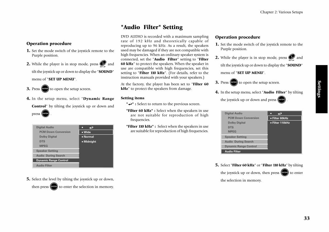
Operation procedure
1. Set the mode switch of the joystick remote to thePurple position.
2. While the player is in stop mode, press SET UP
1 and
tilt the joystick up or down to display the "SOUND"
menu of "SET UP MENU".
3. Press ENTER to open the setup screen.
4. In the setup menu, select "Audio Filter" by tilting
the joystick up or down and press ENTER .
7 Filter 60kHz
7 Filter 110kHz
7 Digital Audio
Dolby Digital
Speaker Setting
Audio During Search
Dynamic Range Control
Audio Filter
DTS
MPEG
PCM Down Conversion
5. Select "Filter 60 kHz" or "Filter 110 kHz" by tilting
the joystick up or down, then press ENTER to enter
the selection in memory.
"Audio Filter" SettingDVD AUDIO is recorded with a maximum samplingrate of 192 kHz and theoretically capable ofreproducing up to 96 kHz. As a result, the speakersused may be damaged if they are not compatible withhigh frequencies. When an ordinary speaker system isconnected, set the "Audio Filter" setting to "Filter60 kHz" to protect the speakers. When the speaker inuse are compatible with high frequencies, set thissetting to "Filter 110 kHz". (For details, refer to theinstruction manuals provided with your speakers.)
At the factory, the player has been set to "Filter 60kHz" to protect the speakers from damage.
Setting items
" " : Select to return to the previous screen.
"Filter 60 kHz" : Select when the speakers in useare not suitable for reproduction of highfrequencies.
"Filter 110 kHz" : Select when the speakers in useare suitable for reproduction of high frequencies.

Sett
ings
34
Chapter 2: Various Setups
"Disc Menu Language" SettingThis setting makes it possible to select the languageused to display the menus recorded in discs. (If theselected language is not used in a specific disc, thelanguage specified as the priority language for the discwill be used.)
At the factory, the language used in displaying themenus of the disc has been set to "English".
Setting items
" " : Select to return to the previous screen.
"English" : Select to display menus in English.
"French" : Select to display menus in French.
"Spanish" : Select to display menus in Spanish.
"German" : Select to display menus in German.
"Italian" : Select to display menus in Italian.
"Chinese" : Select to display menus in Chinese.
"Other ----" : Select to specify the languageusing a code No. listed in the "Disc LanguageCode Table". ‚
¶ The languages displayed with this setting itemare variable depending on country and area.
Operation procedure
1. Set the mode switch of the joystick remote to thePurple position.
2. While the player is in stop mode, press SET UP
1 and
tilt the joystick up or down to display the "VISUAL"
menu of "SET UP MENU".
"Player Menu Language"SettingThis setting makes it possible to select the languageused to display the menus of the player.
At the factory, the language used in displaying themenus of the player has been set to "English".
Setting items
" " : Select to return to the previous screen.
"English" : Select to display menus in English.
"French" : Select to display menus in French.
"Spanish" : Select to display menus in Spanish.
"German" : Select to display menus in German.
"Italian" : Select to display menus in Italian.
"Japanese" : Select to display menus in Japanese.
"Chinese" : Select to display menus in Chinese.
"Taiwanese" : Select to display menus in traditionalChinese letters.
Operation procedure
1. Set the mode switch of the joystick remote to thePurple position.
2. While the player is in stop mode, press SET UP
1 and
tilt the joystick up or down to display the "VISUAL"
menu of "SET UP MENU".
3. Press ENTER to open the setup screen.
4. In the setup menu, select "Player Menu Language"
by tilting the joystick up or down and press ENTER .
7 Japanese
7 Taiwanese
7 Chinese
7
Disc Menu Language
Audio Language
Subtitle Language
Still Mode
FL Mode
SCART Output Select
NTSC = PAL
Player Menu Language
7 Italian
7 Spanish
7 French
7 German
7 English
5. Select the language by tilting the joystick up or
down, then press ENTER to enter the selection in
memory.
"VISUAL" Setting

Settings
Chapter 2: Various Setups
35
3. Press ENTER to open the setup screen.
4. In the setup menu, select "Disc Menu Language"
by tilting the joystick up or down and press ENTER .
7 Other - - - -
7
Disc Menu Language
Audio Language
Subtitle Language
Still Mode
FL Mode
SCART Output Select
NTSC = PAL
Player Menu Language
7 Italian
7 Spanish
7 French
7 German
7 English
5. Select the language by tilting the joystick up or
down, then press ENTER to enter the selection in
memory.
¶ When "Other ----"is selected, set the modeswitch of the joystick remote to the Orangeposition, input the desired code No. using thenumeric keys and press the ENTER button.
¶ If you make a mistake when pressing numerickeys, press the C button and restart the code No.input from the beginning.
"Audio Language" SettingThis setting makes it possible to select the languageused to reproduce the audio recorded in the disc inthe desired language. (If the selected language is notused in a specific disc, the language specified as thepriority language for the disc will be used.)
At the factory, the audio language has been set to"English".
Setting items
" " : Select to return to the previous screen.
"Original" : Select to reproduce audio in thelanguage specified as the priority language bythe disc.
"English" : Select to display menus in English.
"French" : Select to display menus in French.
"Spanish" : Select to display menus in Spanish.
"German" : Select to display menus in German.
"Italian" : Select to display menus in Italian.
"Chinese" : Select to display menus in Chinese.
"Other ----" : Select to specify the languageusing a code No. listed in the "Disc LanguageCode Table". ‚
¶ The languages displayed with this setting itemare variable depending on country and area.
Operation procedure
1. Set the mode switch of the joystick remote to thePurple position.
2. While the player is in stop mode, press SET UP
1 and
tilt the joystick up or down to display the "VISUAL"
menu of "SET UP MENU".
3. Press ENTER to open the setup screen.
4. In the setup menu, select "Audio Language" by
tilting the joystick up or down and press ENTER .
7 Other - - - -
7
Disc Menu Language
Audio Language
Subtitle Language
Still Mode
FL Mode
SCART Output Select
NTSC = PAL
Player Menu Language
7 Italian
7 Spanish
7 French
7 German
7 Original
7 English
5. Select the desired audio language by tilting the
joystick up or down, then press ENTER to enter the
selection in memory.
¶ When "Other ----"is selected, set the modeswitch of the joystick remote to the Orangeposition, input the desired code No. using thenumeric keys and press the ENTER button.
¶ If you make a mistake when pressing numerickeys, press the C button and restart the code No.input from the beginning.

Sett
ings
36
Chapter 2: Various Setups
"Subtitle Language" SettingThis setting makes it possible to select the languageused to display the subtitles recorded in discs. (Whenthe disc does not contain the recording of the selectedsubtitle language, the default subtitle language definedfor the disc will be used.)
At the factory, the language used in displaying thesubtitles has been set to "English".
Setting items
" " : Select to return to the previous screen.
"Auto" : The subtitle language is selected automaticallyaccording to the "Audio language" setting.
Case in which subtitles are not displayed: Whenthe voices are reproduced in the languageselected with "Audio language", the subtitlesare not displayed.
Case in which subtitles are displayed: Whenthe voices cannot be reproduced in thelanguage selected with "Audio language",subtitles are displayed in the language selectedwith "Audio language".
"English" : Select to display menus in English.
"French" : Select to display menus in French.
"Spanish" : Select to display menus in Spanish.
"German" : Select to display menus in German.
"Italian" : Select to display menus in Italian.
"Chinese" : Select to display menus in Chinese.
"Other ----" : Select to specify the languageusing a code No. listed in the "Disc LanguageCode Table". ‚
¶ The languages displayed with this setting itemare variable depending on country and area.
Operation procedure
1. Set the mode switch of the joystick remote to thePurple position.
2. While the player is in stop mode, press SET UP
1 and
tilt the joystick up or down to display the "VISUAL"
menu of "SET UP MENU".
3. Press ENTER to open the setup screen.
4. In the setup menu, select "Subtitle Language" by
tilting the joystick up or down and press ENTER .
7
Disc Menu Language
Audio Language
Subtitle Language
Still Mode
FL Mode
SCART Output Select
NTSC = PAL
Player Menu Language
7 Auto
7 Other - - - -
7 Italian
7 Spanish
7 French
7 German
7 English
5. Select the desired subtitle language by tilting the
joystick up or down, then press ENTER to enter the
selection in memory.
¶ When "Other ----"is selected, set the modeswitch of the joystick remote to the Orangeposition, input the desired code No. using thenumeric keys and press the ENTER button.
¶ If you make a mistake when pressing numerickeys, press the C button and restart the code No.input from the beginning.
"Still Mode" SettingThis setting makes it possible to reduce blur in stillpictures automatically. In addition, it also allows youto select the frame still or field still picture.
At the factory, the player has been set to "Auto", withwhich frame still and field still pictures are switchedautomatically.
Setting items
" " : Select to return to the previous screen.
"Auto" : Frame still and field still pictures areswitched automatically. Usually select thissetting.
"Frame" : Select to display still pictures in a higherpicture quality. (As the field and still pictures aredisplayed alternately, the picture may bluraccordingly.)
"Field" : Select to display still pictures without blur.(As the video information is halved comparedto the frame pictures, the picture qualitydeteriorates accordingly.)

Settings
Chapter 2: Various Setups
37
Operation procedure
1. Set the mode switch of the joystick remote to thePurple position.
2. While the player is in stop mode, press SET UP
1 and
tilt the joystick up or down to display the "VISUAL"
menu of "SET UP MENU".
3. Press ENTER to open the setup screen.
4. In the setup menu, select "Still Mode" by tilting
the joystick up or down and press ENTER .
7
Disc Menu Language
Audio Language
Subtitle Language
Still Mode
FL Mode
SCART Output Select
NTSC = PAL
Player Menu Language
7 Auto
7 Field
7 Frame
5. Select the desired still mode by tilting the joystick
up or down, then press ENTER to enter the selection
in memory.
"FL Mode" SettingThis setting makes it possible to select the brightnessof the player's display panel.
At the factory, the player has been set to "Brightness",with which the display is permanently displayed inhigh brightness.
Setting items
" " : Select to return to the previous screen.
"Brightness" : The display is permanently in highbrightness.
"Dimmer" : The display is permanently displayedin low brightness.
"Auto Off" : The display is disapled when playinga DVD VIDEO or VCD. (The display is shownwhen DVD AUDIO without video is played.) Atthis time, the "Disc 1 to 5" indicators light inlow brightness and other indicators are off.
Operation procedure
1. Set the mode switch of the joystick remote to thePurple position.
2. While the player is in stop mode, press SET UP
1 and
tilt the joystick up or down to display the "VISUAL"
menu of "SET UP MENU".
3. Press ENTER to open the setup screen.
4. In the setup menu, select "FL Mode" by tilting the
joystick up or down and press ENTER .
7 Dimmer
7 Brightness
7 Auto Off
7
Disc Menu Language
Audio Language
Subtitle Language
Still Mode
FL Mode
SCART Output Select
NTSC = PAL
Player Menu Language
5. Select the FL mode by tilting the joystick up or
down, then press ENTER to enter the selection in
memory.

Sett
ings
38
Chapter 2: Various Setups
Operation procedure
1. Set the mode switch of the joystick remote to thePurple position.
2. While the player is in stop mode, press SET UP
1 and
tilt the joystick up or down to display the "VISUAL"
menu of "SET UP MENU".
3. Press ENTER to open the setup screen.
4. In the setup menu, select "NTSC = PAL" by tilting
the joystick up or down and press ENTER .
7 Off
7 On
7
Disc Menu Language
Audio Language
Subtitle Language
Still Mode
FL Mode
SCART Output Select
NTSC = PAL
Player Menu Language
5. Select "On" or "Off" by tilting the joystick up or
down, then press ENTER to enter the selection in
memory.
"NTSC = PAL" Setting(Except for the U.S.A. and Canada)
This setting makes it possible to play an NTSC-formatdisc by converting signal into PAL format. Select "On"when it is required to convert NTSC-format discs intoPAL signals.
Setting items" " : Select to return to the previous screen.
"On" : Select to enable conversion from NTSC toPAL.
"Off" : Select to disable conversion from NTSC toPAL.
"SCART Output Select" Setting(For Europe and U.K.)
This setting makes it possible to select the outputsignals from the TV SCART connector of the player.(The VCR SCART connector always outputs compositevideo signals so its output signals cannot be selected.)
When the "RGB" output signals are selected with thissetting, the COMPONENT VIDEO OUTPUT jacks ofthe player do not output any video signal.
At the factory, the TV SCART connector output signalsof the player has been set to "Composite".
Setting items" " : Select to return to the previous screen.
"Composite" : Select to output composite videosignal.
"S Video" : Select to output S Video signals.
"RGB" : Select to output RGB signals.

Settings
Chapter 2: Various Setups
39
Operation procedure
1. Set the mode switch of the joystick remote to thePurple position.
2. While the player is in stop mode, press SET UP
1 and
tilt the joystick up or down to display the "VISUAL"
menu of "SET UP MENU".
3. Press ENTER to open the setup screen.
4. In the setup menu, select "SCART Output Select"
by tilting the joystick up or down and press ENTER .
7 S Video
7 Composite
7 RGB
7
Disc Menu Language
Audio Language
Subtitle Language
Still Mode
FL Mode
SCART Output Select
NTSC = PAL
Player Menu Language
5. Select the desired output signals by tilting the
joystick up or down, then press ENTER to enter the
selection in memory.

Sett
ings
40
Chapter 2: Various Setups
Disc Language Code Table
Cord No. : Language
Afar
Abkhazian
Afrikaans
Amharic
Arabic
Assamese
Aymara
Azerbaijani
Bashkir
Byelorussian
Bulgarian
Bihari
Bengali; Bangla
Tibetan
Breton
Catalan
Corsican
Czech
Welsh
Danish
German
Bhutani
Greek
English
Esperanto
Spanish
Estonian
Basque
Persian
Finnish
Fiji
Faroese
French
6565 :
6566 :
6570 :
6577 :
6582 :
6583 :
6588 :
6590 :
6665 :
6669 :
6671 :
6672 :
6678 :
6679 :
6682 :
6765 :
6779 :
6783 :
6789 :
6865 :
6869 :
6890 :
6976 :
6978 :
6979 :
6983 :
6984 :
6985 :
7065 :
7073 :
7074 :
7079 :
7082 :
Cord No. : Language
7089 :
7165 :
7168 :
7176 :
7178 :
7185 :
7265 :
7273 :
7282 :
7285 :
7289 :
7365 :
7378 :
7383 :
7384 :
7387 :
7465 :
7473 :
7487 :
7565 :
7575 :
7576 :
7577 :
7578 :
7579 :
7583 :
7585 :
7589 :
7665 :
7678 :
7679 :
7684 :
7686 :
Frisian
Irish
Scots Gaelic
Galician
Guarani
Gujarati
Hausa
Hindi
Croatian
Hungarian
Armenian
Interlingua
Indonesian
Icelandic
Italian
Hebrew
Japanese
Yiddish
Javanese
Geogian
Kazakh
Greenlandic
Cambodian
Kannada
Korean
Kashmiri
Kurdish
Kirghiz
Latin
Lingala
Laothian
Lithuanian
Latvian; Lettish
7771 :
7773 :
7775 :
7776 :
7778 :
7779 :
7782 :
7783 :
7784 :
7789 :
7865 :
7869 :
7876 :
7879 :
7982 :
8065 :
8076 :
8083 :
8084 :
8185 :
8277 :
8279 :
8285 :
8365 :
8368 :
8372 :
8373 :
8375 :
8376 :
8377 :
8378 :
8379 :
8381 :
Malagasy
Maori
Macedonian
Malayalam
Mongolian
Moldavian
Marathi
Malay
Maltese
Burmese
Nauru
Nepali
Dutch
Nowegian
Oriya
Punjabi
Polish
Pashto; Pushto
Portuguese
Quechua
Rhaeto-Romance
Romanian
Russian
Sanskrit
Sindhi
Serbo-Croatian
Singhalese
Slovak
Slovenian
Samoan
Shona
Somali
Albanian
8382 :
8385 :
8386 :
8387 :
8465 :
8469 :
8471 :
8472 :
8473 :
8475 :
8476 :
8479 :
8482 :
8484 :
8487 :
8575 :
8582 :
8590 :
8673 :
8679 :
8779 :
8872 :
8979 :
9072 :
9085 :
Serbian
Sundanese
Swedish
Swahili
Tamil
Telugu
Tajik
Thai
Tigrinya
Turkmen
Tagalog
Tonga
Turkish
Tatar
Twi
Ukrainian
Urdu
Uzbek
Vietnamese
Volapük
Wolof
Xhosa
Yoruda
Chinese
Zulu
Cord No. : Language Cord No. : Language

Gen
eral Kn
ow
ledge
DVF-R9030
41
Chapter 3: Other Information
Chapter 3: Other Information
Maintenance of the unitWhen the front panel or case becomes dirty, wipe with
a soft, dry cloth. Do not use thinner, benzine, alcohol,
etc. for these agents may cause discoloration.
In regard to contact cleanerDo not use contact cleaners because it could cause a
malfunction. Be specially careful not to use contact
cleaners containing oil, for they may deform the plastic
component.
Never play a cracked or warped discDuring playback, the disc rotates at high speed in the
player.
Therefore, to avoid danger, never use a cracked or
deformed disc or a disc repaired with tape or adhesive
agent.
Please do not use discs which are not round because
they may cause a malfunction.
Disc accessoriesThe disc accessories (stabilizer, protection sheet,
protection ring, etc.) which are marketed for improving
the sound quality or protecting discs as well as the
disc cleaner should not be used with this system
because they may cause malfunction.
To Be Noted
Disc handling precautionsHandling : Hold a disc taking care not to touch the disc
surface.
Sticker
Sticky paste
Do not attach paper or tape to either the playing
side or the label side of the discs.
Cleaning : If fingerprints or foreign matter become
attached to the disc, lightly wipe the disc with a soft
cotton cloth (or similar) from the center of the disc
outwards in a radial manner.
Storage : When a disc is not to be played for a long
period of time, remove it from the player and store it
in its case.
Manufactured under license from DolbyLaboratories. “DOLBY” and the double-D symbol are trademarksof Dolby Laboratories. Confidential Unpublished Works. ©1992-
1997 Dolby Laboratories. All rights reserved.
Manufactured under license from Digital Theater
Systems, Inc. US Pat. No. 5,451,942 and other worldwide patentsissues and pending. “DTS” and “DTS Digital Surround” aretrademarks of Digital Theater Systems, Inc. © 1996 Digital TheaterSystems, Inc. All rights reserved.
It is prohibited by laws to duplicate, broadcast, perform in publicor rent a disc without the permission of the copyright owners.
This product is compatible with the Macrovision type copyprotection. Some discs contain the recording of copy inhibitsignals, and the video may be disturbed when the video of suchdiscs is recorded onto a VCR and played back.
This product incorporates copyright protection technology thatis protected by method claims of certain U.S. patents and otherintellectual property rights owned by Macrovision Corporationand other rights owners. Use of this copyright protectiontechnology must be authorized by Macrovision Corporation,and is intended for home and other limited viewing uses onlyunless otherwise authorized by Macrovision Corporation.Reverse engineering or disassembly is prohibited.

Gen
eral
Kn
ow
led
ge
42
Chapter 3: Other Information
Caution on condensationCondensation (of dew) may occur inside the unit whenthere is a great difference in temperature between thisunit and the outside.
This unit may not function properly if condensationoccurs. In this case, leave the unit for a few hours andrestart the operation after the condensation has dried up.
Be specially cautious against condensation in afollowing circumsatance:
When this unit is carried from a place to another acrossa large difference in temperature, when the humidityin the room where this unit is installed increases, etc.
Transport or moving precautionsWhen transporting or moving the player, first remove the
disc and observe the following procedure.
1. Turn the player power on.
2. Wait for a few seconds, until the display shows "NO
DISC".
3. Turn the player power off by pressing - ON – OFF
POWER
.
DTS disclaimer clauseDTS Digital Surround™ is a discrete 5.1 channel digital
audio format available on CD, LD, and DVD software
which consequently cannot be decoded and played
back inside most CD, LD, or DVD players. For this
reason, when DTS-encoded software is played back
through the analog outputs of the CD, LD, or DVD
player, excessive noise will be exhibited. To avoid
possible damage to the audio system, proper
precautions should taken by the consumer if the analog
outputs are connected directly to an amplification
system. To enjoy DTS Digital Surround™ playback, an
external 5.1 channel DTS Digital Surround™ decoder
system must be connected to the digital output (S/P
DIF, AES/EBU, or TosLink) of the CD, LD or DVD
player.
This unit is equipped with DTS Digital Surround™
decoder.
Location: Laser Pick-up Unit Cover inside thisproduct
CAUTION- LASER RADIATION WHEN OPEN.
DO NOT STARE INTO BEAM.
CAUTION (For the U.S.A.)
Use of controls or adjustments or performance ofprocedures other than those specified herein may resultin hazardous radiation exposure.
In compliance with Federal Regulations, following arereproductions of labeles on, or inside the product relatingto laser product safety.
KENWOOD CORPORATION2967-3, ISHIKAWA-CHO,HACHIOJI-SHI,TOKYO, JAPAN
KENWOOD CORP. CERTIFIES THISEQUIPMENT CONFORMS TO DHHSREGULATIONS NO. 21 CFR1040.10, CHAPTER 1, SUBCHAPTER J.
Location: Back Panel
FCC WARNING (For the U.S.A.)
This equipment may generate or use radio frequencyenergy. Changes or modifications to this equipmentmay cause harmful interference unless themodifications are expressly approved in theinstruction manual. The user could lose theauthority to operate this equipment if anunauthorized change or modification is made.
NOTE :
This equipment has been tested and found tocomply with the limits for a Class B digital device,pursuant to Part 15 of the FCC Rules. These limitsare designed to provide reasonable protectionagainst harmful interference in a residentialinstallation. This equipment may cause harmfulinterference to radio communications, if it is notinstalled and used in accordance with theinstructions. However, there is no guarantee thatinterference will not occur in a particularinstallation. If this equipment does cause harmfulinterference to radio or television reception, whichcan be determined by turning the equipment offand on, the user is encouraged to try to correct theinterference by one or more of the followingmeasures:
––– Reorient or relocate the receiving antenna.
––– Increase the separation between the equipmentand receiver.
––– Connect the equipment into an outlet on acircuit different from that to which the receiveris connected.
––– Consult the dealer or an experienced radio / TVtechnician for help.

Gen
eral Kn
ow
ledge
DVF-R9030
43
Chapter 3: Other Information
Linear PCM (Pulse Code Modula-
tion): Audio signal format without
using compression. In the DVD
which has a very large disc capacity,
the linear PCM signal using high
sampling rate can be recorded.
Packed PCM : The packed PCM
(P.PCM) signal is obtained by com-
pressing the linear PCM signal fea-
turing large data amount and high
sampling rate. With this compres-
sion, the signal before compression
can be restored perfectly.
Sampling rate: Sampling refers to con-
verting an analog signal into digital
signal by slicing the analog signal
into fine parts at a certain time in-
terval and digitizing every sliced part.
The sampling rate is the count of slic-
ing per second. The original sound
can be reproduced more faithfully
when the sampling rate is higher.
Quantization bit: The quantization bit
count refers to the number used in
digitizing the sliced parts obtained
by slicing the analog signal as de-
scribed above. The quantization bit
count is the number of bits used in
Glossary
digitization per second. The original
sound can be reproduced more faith-
fully when the quantization bit
count is larger.
Bitstream (DVD): This is the generic
name given for the flow of data
based on a standard such as Dolby
Digital, DTS, MPEG, etc.
Downmixing: Conversion of multi-
channel audio signals of DVD or
DTS-CD into 2-channel stereo sig-
nals.
Downconversion: Conversion of PCM
signal with high sampling rate such
as 96 kHz and 192 kHz into a signal
with a sampling rate of 48 kHz or
44.1 kHz.
Decoder: A device for restoring stan-
dard audio signal from audio data
recorded based on coding into DVD
data, etc. This processing is referred
to as decoding.
Dolby Digital: A digital audio compres-
sion technology developed by Dolby
Laboratories, Inc. It is compatible
with 5.1-channel surround audio as
well as 2-channel stereo, and capable
of recording a large amount of au-
dio data efficiently in a disc.
DTS : Digital surround system devel-
oped by Digital Theater Systems, Inc.
MPEG (Moving Picture Expert
Group) (DVD, VCD): A digital
video and audio compression and
decompression system which is stan-
dardized as an international stan-
dard.
Aspect ratio: The ratio between the
horizontal and vertical sizes of pic-
ture displayed on a TV screen. The
aspect ratio of ordinary TV is 4:3, and
that of widescreen TV is 16:9.
Pan & scan (DVD): Method of display-
ing a horizontally-long picture re-
corded in 16:9 aspect ratio on a 4:3
TV screen by trimming part of picture.
In general, the trimming positions
for pan & scan are determined uni-
formly by the reproducing device.
However, the pan & scan of DVD al-
lows the software producer to specify
the trimming positions to be used
in playback.
Letterbox (DVD): Method of display-
ing a horizontally-long picture re-
corded in 16:9 aspect ratio on a 4:3
TV screen by attaching bands at the
top and bottom of the screen and
displaying the horizontally-long pic-
ture at the center of screen.
Frame (DVD, VCD): Each frame of a
moving picture, that is displayed 30
times a second with NTSC and 25
times a second with PAL. These TV
formats reproduce moving pictures
by displaying still pictures sequen-
tially.
Field (DVD, VCD): Part of a frame
obtained by diving the video data of
each frame by two. Each frame of
ordinary TV is constitute by display-
ing the fields alternately.
Frame still/Field still (DVD, VCD):
Types of still pictures obtained by
temporarily stopping a moving pic-
ture. The frame still picture may pro-
duce blur in the picture because it
displays two specific fields alter-
nately, but the picture quality is
higher. The field still picture has

Gen
eral
Kn
ow
led
ge
44
Chapter 3: Other Information
lower picture quality because it uses
half the picture information of frame
still, but is not accompanies with
picture blur.
IPB display (DVD): With the MPEG2
which is one of the video displaymethods of DVD, each picture is di-vided into the following three pic-ture types before being coded in digi-tal signal.
I-picture (in-frame coding): Thisis the standard video and can con-stitute a picture by itself. As the high-est picture quality can be obtained,the still image of I-picture is mostsuitable for use when adjusting thepicture quality.
P-picture (forward predictioncoding): Picture calculated based onpast pictures (I-picture or P-picture).
B-picture (bidirectional predic-tion coding): Picture calculated bycomparing the previous and nextpictures (I-pictures or P-pictures).This picture type contains least
amount of video information.
Dynamic range: Difference between
the minimum reproducible audio
signal and maximum reproducible
audio signal.

Gen
eral Kn
ow
ledge
DVF-R9030
45
Chapter 3: Other Information
A
accessories .................................................. 3
aspect ratio ............................................... 20
audio language ....................................... 35
audio filter .............................................. 33
B
bitstream ..................................... 26, 27, 28
C
connection
AV amplifier ................................ 12, 13
stereo system ................................ 10, 11
TV.................................................. 10, 11
D
delay time ................................................ 30
digital output
Dolby Digital ................................ 26
DTS ................................................ 27
MPEG ............................................ 28
PCM downconversion ................. 26
disc menu language ............................... 34
DVD video mode .................................... 22
dynamic range control ........................... 32
F
FL mode ...................................................37
H
humidity ..................................................42
I
IPB ............................................................24
J
joystick .................................................... 15
joystick remote
installing the batteries ..................... 14
control range .................................... 14
L
language code ......................................... 40
N
NTSC .......................................................... 8
M
MAIN ....................................................... 18
maintenance ............................................ 41
microcomputer resetting .......................... 9
O
on screen message .................................. 23
OSD position .......................................... 22
P
PAL..............................................................8
PCM ......................................................... 26
playable disc .............................................. 5
player menu language ............................ 34
power supply .......................................... 14
R
region code ................................................ 6
S
setting screen .......................................... 15
IPB ..................................................... 24
audio filter ........................................ 33
audio language ................................. 35
basic operation ................................. 15
digital output .................................... 26
MPEG ............................................ 28
DTS ................................................ 27
Dolby Digital ................................ 26
PCM downconversion ................. 26
disc menu language ......................... 34
DVD video mode ............................. 22
dynamic range control ..................... 32
FL mode ............................................ 37
MAIN ................................................. 18
on screen message ............................ 23
OSD position .................................... 22
player menu language ...................... 34
SCART output select ......................... 38
search audio ...................................... 32
SOUND ............................................. 26
speaker setting .................................. 28
still mode .......................................... 36
subtitle language .............................. 36
TV aspect ratio .................................. 20
Index
TV mode ............................................ 20
TV monitor ........................................ 21
viewing restriction ............................ 18
VISUAL .............................................. 34
standby mode ......................................... 14
T
TV aspect ratio .........................................20
TV mode ...................................................20
TV monitor .............................................. 21
U
unplayable disc ..........................................5
V
video formats ............................................. 8
video monitor .......................................... 21
viewing restriction .................................. 18
VISUAL .................................................... 34

Gen
eral
Kn
ow
led
ge
46
Chapter 3: Other Information
Video SectionComposite video output level ................................... 1 Vp-p (75 Ω)
S-video output level
(Y-signal) .............................................................. 1 Vp-p (75 Ω)
(C-signal) ...................................................... 0.286 Vp-p (75 Ω)
Component video output level
(Y-signal) .............................................................. 1 Vp-p (75 Ω)
(Cb-signal) ........................................................ 0.7 Vp-p (75 Ω)
(Cr-signal) ......................................................... 0.7 Vp-p (75 Ω)
RGB output level (SCART) ...................................... 0.7 Vp-p (75 Ω)
Video signal to noise ratio ....................................................... 65 dB
Horizontal resolution ......................................................... 500 lines
Laser SectionWavelength .................................................................... 660~676 nm
Laser power class ............................................................ class 2 (IEC)
Format sectionFormat ............................. DVD audio ver. 1.2 / DVD video ver.1.1
Laser ............................................................. Semiconductor laserVideo output format ......................................................... NTSC/PAL
Audio sectionFrequency response
Sampling frequency: 44.1kHz (CD only) ........... 4 Hz~20 kHz
Sampling frequency: 48 kHz ............................... 4 Hz~22 kHz
Sampling frequency: 96 kHz ............................... 4 Hz~44 kHz
Sampling frequency: 192 kHz (DVD AUDIO only)
........................................................................ 4 Hz~88 kHz
Signal to noise ratio ............................................. More than 120 dB
Dynamic range ..................................................... More than 100 dB
Total harmonic distortion ................... Less than 0.0025 % (1kHz)
Channel separation .................................. More than 95 dB (1kHz)
Analog output level/impedance
MIX LINE OUTPUT ................................................... 2 V/ 510 Ω6 CH. OUTPUT ........................................................ 2 V / 510 Ω
Digital output level/impedance
COAXIAL ............................................................ 0.5 Vp-p/ 75 ΩOPTICAL (Wave length 660 nm) ............... -21 dBm ~ -15 dBm
Headphone output ........... 30 mW/ 32 Ω load (Phones level MAX)
KENWOOD follows a policy of continuous
advancements in development. For this reason
specifications may be changed without notice.
Sufficient performance may not be exhibited at
extremely cold locations (Where water freezes).
Specifications
General Section
[DV-4900, DVF-R9030]
Power consumption ................................................................. 35 W
Dimensions ............................................... W : 474 mm (18-11/16”)
..................................................... H : 127 mm (5”)
..................................................... D : 410 mm (16-1/8”)
Weight (net) .............................................................. 7.4 kg (16.3 lb)
[DV-4070, DVF-R7030]
Power consumption ................................................................. 35 W
Dimensions ............................................... W : 440 mm (17-5/16”)
..................................................... H : 127 mm (5”)
..................................................... D : 410 mm (16-1/8”)
Weight (net) .............................................................. 6.3 kg (13.9 lb)

MEMORANDUM

For your recordsRecord the serial number, found on the back of the unit, in the spaces designated on the warranty card, and in
the space provided below. Refer to the model and serial numbers whenever you call upon your dealer for
information or service on this product.
Model ............................. Serial Number .............................