02er
TRANSCRIPT

1
Entity-Relationship Model
Gang Qian
Department of Computer ScienceUniversity of Central Oklahoma

2
Overview (Chapters 7 and 9)
Overview of Database Design Process ER Model Concepts
Entities and Attributes Entity Types, Value Sets, and Key Attributes Relationships and Relationship Types Weak Entity Types Roles and Attributes in Relationship Types
ER Diagrams – Notation ER-to-Relational Mapping Algorithm

3
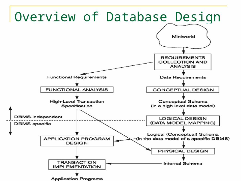
Overview of Database Design Process Two main activities:
Database design Applications design
Our focus is on database design To design the conceptual and logical schema for
a database application Applications design focuses on the programs
and interfaces that access the database Generally considered part of software engineering
4
Overview of Database Design Process

5
ER Model
Data requirement specification is first captured by using an ER model The ER model is then mapped into a relational
data model Why use ER model first?
Real world information is more naturally mapped into ER model than into relational data model
ER model can explicitly capture the data relationships
ER model is easily reviewed and modified at design time

6
ER Model Concepts
Entities and Attributes Entities are specific objects or things in the mini-world that
are represented in the database For example, the EMPLOYEE John Smith, the Research
DEPARTMENT, the ProductX PROJECT Attributes are properties used to describe an entity.
For example an EMPLOYEE entity may have the attributes Name, SSN, Address, Sex, BirthDate
A specific entity will have a value for each of its attributes. For example a specific employee entity may have
Name='John Smith', SSN='123456789', Address ='731, Fondren, Houston, TX', Sex='M', BirthDate='09-JAN-55‘
Each attribute has a value set (or data type) associated with it – e.g. integer, string, subrange, enumerated type, …

7
Entity Types and Key Attributes Entities with the same basic attributes
are grouped or typed into an entity type For example, the entity type EMPLOYEE
and PROJECT An attribute of an entity type for which
each entity must have a unique value is called a key attribute of the entity type For example, SSN of EMPLOYEE

8
Example: Entity Type CAR with two keys and a corresponding Entity Set
9
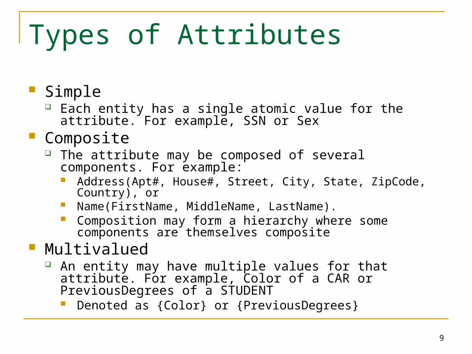
Types of Attributes
Simple Each entity has a single atomic value for the attribute. For
example, SSN or Sex Composite
The attribute may be composed of several components. For example: Address(Apt#, House#, Street, City, State, ZipCode, Country), or Name(FirstName, MiddleName, LastName). Composition may form a hierarchy where some components
are themselves composite Multivalued
An entity may have multiple values for that attribute. For example, Color of a CAR or PreviousDegrees of a STUDENT Denoted as {Color} or {PreviousDegrees}

10
In general, composite and multivalued attributes may be nested arbitrarily to any number of levels, although this is rare For example, PreviousDegrees of a STUDENT is
a composite multivalued attribute denoted by {PreviousDegrees (College, Year, Degree, Field)}
Multiple PreviousDegrees values can exist Each has four subcomponent attributes:
College, Year, Degree, Field

11
Stored attributes are attributes whose values are stored in the table Most attributes are stored attributes
Derived attributes are attributes whose values can be computed from values of other attributes on the fly when needed Example: The attribute age can be derived from
the attribute birthdate
12
Displaying an Entity type
In ER diagrams, an entity type is displayed in a rectangular box
Attributes are displayed in ovals Each attribute is connected to its entity type Components of a composite attribute are
connected to the oval representing the composite attribute
Each key attribute is underlined Multivalued attributes displayed in double ovals

13
More on Key Attributes
A key attribute may be composite VehicleTagNumber is a key of the CAR entity
type with components (Number, State) An entity type may have more than one key
The CAR entity type may have two keys: VehicleIdentificationNumber (popularly called VIN) VehicleTagNumber (Number, State), aka license plate
number.
Each key is underlined in the ER diagram

15
Example: COMPANY Database We need to create a database schema design
based on the following (simplified) requirements of the COMPANY Database: The company is organized into DEPARTMENTs. Each
department has a name, unique number and an employee who manages the department. We keep track of the start date of the department manager. A department may have several locations
Each department controls a number of PROJECTs. Each project has a unique name, unique number and is located at a single location

16
We store each EMPLOYEE’s social security number, address, salary, sex, and birthdate. Each employee works for one department but may work on
several projects We keep track of the number of hours per week that an
employee currently works on each project We also keep track of the direct supervisor of each employee
Each employee may have a number of DEPENDENTs For each dependent, we keep track of their name, sex,
birthdate, and relationship to the employee
What is the next step?

17
Attribute or Entity Types?
Sometimes it may be unclear whether a “noun” appears in the design should be an attribute of an entity or a separate entity itself
Example: A Team in a City. Should City be an entity itself or just an attribute of Team
Such a decision often depends on the application If only the city name is used and other information about
the city is not needed in the application, then we can let City be an attribute of Team
If the application also uses other city information, such as population, state or even median salary, then we need to set City as an entity (type)
How about department locations?

18
Initial Design of Entity Types for the COMPANY Database Schema Based on the requirements, we can identify four
initial entity types in the COMPANY database: DEPARTMENT PROJECT EMPLOYEE DEPENDENT Why not Manager or Department Number?
Their attributes can be derived from the requirements description

19
Introducing Relationships
Entity types are not enough Some aspects in the requirements should be
represented as relationships ER model has three main concepts:
Entities (and their entity types and entity sets) Attributes (simple, composite, multivalued) Relationships (and their relationship types and
relationship sets)

20
Relationships and Relationship Types A relationship relates one or more distinct entities
with a specific meaning For example, EMPLOYEE John Smith works on the ProductX
PROJECT, or EMPLOYEE Franklin Wong manages the Research DEPARTMENT.
Relationships of the same type are grouped or typed into a relationship type. For example, the WORKS_ON relationship type in which
EMPLOYEEs and PROJECTs participate, or the MANAGES relationship type in which EMPLOYEEs and DEPARTMENTs participate.
The degree of a relationship type is the number of participating entity types Both MANAGES and WORKS_ON are binary relationships

25
In ER diagrams, we represent the relationship type as follows: Diamond-shaped box is used to display a relationship type Connected to the participating entity types via lines

26
Attributes or Relationship Types? Verbs usually describe a relationship type Sometimes it may be unclear whether a “noun”
appears in the design should be an attribute of an entity or a separate relationship type
Example: Manager SSN of a Department Should Manager SSN be an attribute or a relationship
type? Such a decision often depends on the description of
the “noun” If the description involves other entity types, it is a
relationship type, such as the manager of a department Otherwise it is an attribute, such as department name

27
Refining the COMPANY Database Schema by Introducing Relationships By examining the requirements, six relationship
types are identified All are binary relationships (degree 2) Listed below with their participating entity types:
WORKS_FOR (between EMPLOYEE, DEPARTMENT) MANAGES (also between EMPLOYEE, DEPARTMENT) CONTROLS (between DEPARTMENT, PROJECT) WORKS_ON (between EMPLOYEE, PROJECT) SUPERVISION (between EMPLOYEE (as subordinate),
EMPLOYEE (as supervisor)) DEPENDENTS_OF (between EMPLOYEE, DEPENDENT)

28
29
Discussion on Relationship Types More than one relationship type can exist
between the same participating entity types MANAGES and WORKS_FOR are distinct
relationship types between EMPLOYEE and DEPARTMENT

30
Recursive Relationship Type
Recursive relationship type: a relationship type with the same participating entity type in distinct roles Example: the SUPERVISION relationship
supervisor (or boss) supervisee (or subordinate)
In ER diagram, need to display role names to distinguish participations

31

32
Weak Entity Types
An entity that does not have a key attribute A weak entity must participate in an identifying relationship
type with an owner or identifying entity type Entities are identified by the combination of:
A partial key of the weak entity type The particular entity they are related to in the identifying entity
type Example:
A DEPENDENT entity is identified by the dependent’s first name, and the specific EMPLOYEE with whom the dependent is related
Name of DEPENDENT is the partial key DEPENDENT is a weak entity type EMPLOYEE is its identifying entity type via the identifying
relationship type DEPENDENT_OF

33
Constraints on Relationships
Constraints on relationship types Cardinality Ratio (specifies maximum participation)
One-to-one (1:1) One-to-many (1:N) or Many-to-one (N:1) Many-to-many (N:M)
Existence Dependency Constraint (specifies minimum participation) (also called participation constraint) zero (optional participation, not existence-dependent) one or more (mandatory participation, existence-dependent)

36
Notation for Constraints on Relationships Cardinality ratio (of a binary relationship): 1:1,
1:N, or N:M Shown by placing appropriate numbers on the
relationship edges Participation constraint (on each participating
entity type): total (called existence dependency) or partial. Total shown by double line, partial by single line.
37
Attributes of Relationship types A relationship type can have attributes:
For example, HoursPerWeek of WORKS_ON Its value for each relationship instance describes the
number of hours per week that an EMPLOYEE works on a PROJECT.
A value of HoursPerWeek depends on a particular (employee, project) combination

38

39
Summary of notation for ER diagrams

40
41
Relationships of Higher Degree Relationship types of degree 2 are called
binary Relationship types of degree 3 are called
ternary and of degree n are called n-ary In general, an n-ary relationship is not
equivalent to n binary relationships Constraints are harder to specify for higher-
degree relationships (n > 2) than for binary relationships

42
Discussion of n-ary relationships (n > 2) In general, 3 binary relationships can represent
different information than a single ternary relationship (see Figures a and b on next slide)
If needed, the binary and n-ary relationships can all be included in the schema design (see Figures a and b, where all relationships convey different meanings)

43
44
Discussion of n-ary relationships (n > 2) If a particular binary relationship can be
derived from a higher-degree relationship at all times, then it is redundant For example, the TAUGHT_DURING binary
relationship (see next slide) can be derived from the ternary relationship OFFERS (based on the meaning of the relationships)

45

46
Displaying constraints on higher-degree relationships Displaying a 1, M, or N indicates constraints
An M or N indicates no constraint A 1 indicates that an entity can participate in at
most one relationship instance that has a particular combination of the other participating entities

Design ER-Diagram in This Order Forget about tables
Focus on entities and their relationships Indentify all the entity types first Then identify attributes and relationships
47

48
Extended Entity-Relationship (EER) Model (in next chapter) The entity relationship model in its original
form did not support the specialization and generalization abstractions
Next lecture illustrates how the ER model can be extended with Type-subtype and set-subset relationships Specialization/Generalization Hierarchies Notation to display them in EER diagrams

49
ER-to-Relational Mapping Algorithm Step 1: Mapping of Regular Entity Types Step 2: Mapping of Weak Entity Types Step 3: Mapping of Binary 1:1 Relation Types Step 4: Mapping of Binary 1:N Relationship Types Step 5: Mapping of Binary M:N Relationship Types Step 6: Mapping of Multivalued attributes Step 7: Mapping of N-ary Relationship Types

50
ER-to-Relational Mapping Algorithm Step 1: Mapping of Regular Entity Types
For each regular (strong) entity type E in the ER diagram, create a relation R that includes all the simple attributes (or simple components of composite attributes) of E
Choose one of the key attributes as the primary key for R If the chosen key of E is composite, the set of simple
attributes that form it will together form the primary key of R Example: We create the relations EMPLOYEE,
DEPARTMENT, and PROJECT in the relational schema corresponding to the regular entities in the ER diagram
SSN, DNUMBER, and PNUMBER are the primary keys for the relations EMPLOYEE, DEPARTMENT, and PROJECT as shown.

51

52

53
Step 2: Mapping of Weak Entity Types For each weak entity type W in the ER diagram with owner entity
type E, create a relation R & include all simple attributes (or simple components of composite attributes) of W as attributes of R
Also, include as foreign key attributes of R the primary key attribute(s) of the relation(s) that correspond to the owner entity type(s)
The primary key of R is the combination of the primary key(s) of the owner(s) and the partial key of the weak entity type W
Example: Create the relation DEPENDENT in this step to correspond to the weak entity type DEPENDENT.
Include the primary key SSN of the EMPLOYEE relation as a foreign key attribute of DEPENDENT (renamed to ESSN).
The primary key of the DEPENDENT relation is the combination {ESSN, DEPENDENT_NAME} because DEPENDENT_NAME is the partial key of DEPENDENT.

54
Step 3: Mapping of Binary 1:1 Relation Types For each binary 1:1 relationship type R in the ER
schema, identify the relations S and T that correspond to the entity types participating in R.
There are three possible approaches:1. Foreign Key approach: Choose one of the relations-
say S-and include a foreign key in S the primary key of T.
It is better to choose an entity type with total participation in R in the role of S
The foreign key need to be set as unique For total participation, the foreign key need to be set as NOT
NULL (Depend on the situation) Example: 1:1 relation MANAGES is mapped by choosing
DEPARTMENT to serve in the role of S, because its participation in the MANAGES relationship type is total.
55
2. Merged relation option: An alternate mapping of a 1:1 relationship type is possible by merging the two entity types and the relationship into a single relation.
This may be appropriate when both participations are total The key attributes of the joining relation should be set as
UNIQUE and NOT NULL

56
Step 4: Mapping of Binary 1:N Relationship Types For each regular binary 1:N relationship type R, identify
the relation S that represents the participating entity type at the N-side of the relationship type
Include as foreign key in S the primary key of the relation T that represents the other entity type participating in R
If the relationship on the N-side is total, the foreign key must be NOT NULL (Dependent on the situation)
Include any simple attributes of the 1:N relation type as attributes of S
Example: 1:N relationship types WORKS_FOR, CONTROLS, and SUPERVISION in the figure.
For WORKS_FOR we include the primary key DNUMBER of the DEPARTMENT relation as foreign key in the EMPLOYEE relation and call it DNO
57
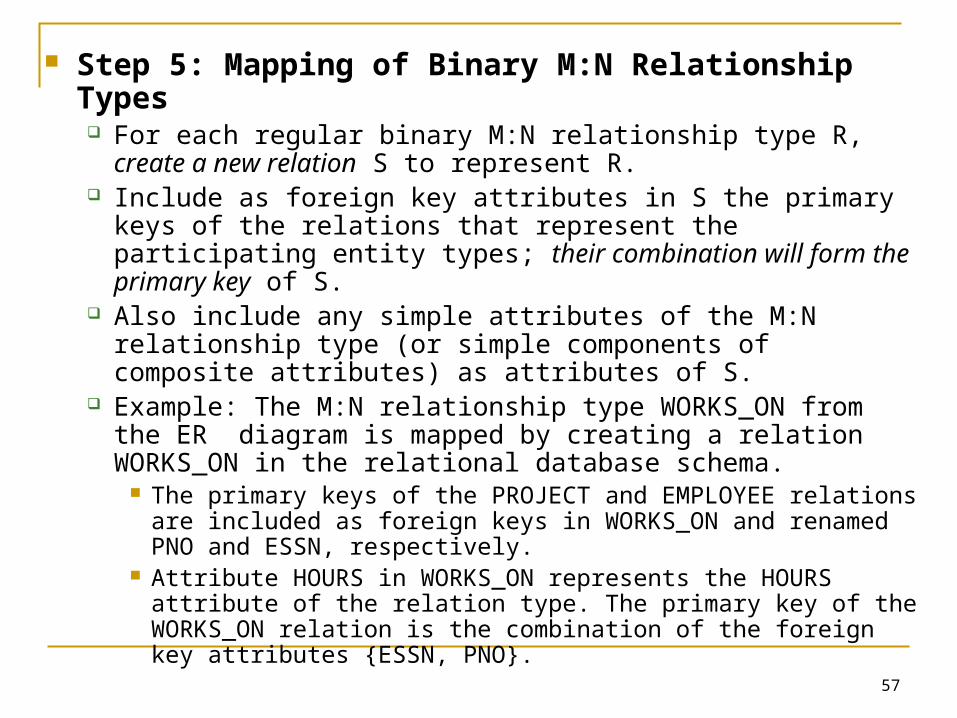
Step 5: Mapping of Binary M:N Relationship Types For each regular binary M:N relationship type R, create a new
relation S to represent R. Include as foreign key attributes in S the primary keys of the
relations that represent the participating entity types; their combination will form the primary key of S.
Also include any simple attributes of the M:N relationship type (or simple components of composite attributes) as attributes of S.
Example: The M:N relationship type WORKS_ON from the ER diagram is mapped by creating a relation WORKS_ON in the relational database schema.
The primary keys of the PROJECT and EMPLOYEE relations are included as foreign keys in WORKS_ON and renamed PNO and ESSN, respectively.
Attribute HOURS in WORKS_ON represents the HOURS attribute of the relation type. The primary key of the WORKS_ON relation is the combination of the foreign key attributes {ESSN, PNO}.

58
Step 6: Mapping of Multivalued attributes. For each multivalued attribute A, create a new relation R This relation R will include an attribute corresponding to A,
plus the primary key attribute K-as a foreign key in R-of the relation that represents the entity type of relationship type that has A as an attribute.
The primary key of R is the combination of A and K. If the multivalued attribute is composite, we include its simple components.
Example: The relation DEPT_LOCATIONS is created. The attribute DLOCATION represents the multivalued attribute
LOCATIONS of DEPARTMENT, while DNUMBER-as foreign key-represents the primary key of the DEPARTMENT relation.
The primary key of R is the combination of {DNUMBER, DLOCATION}.
59
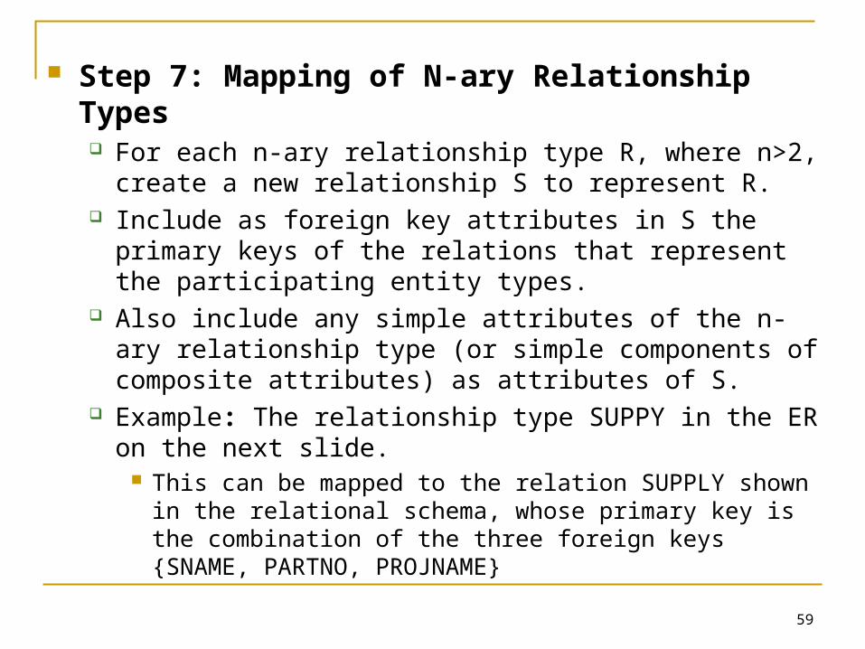
Step 7: Mapping of N-ary Relationship Types For each n-ary relationship type R, where n>2, create a
new relationship S to represent R. Include as foreign key attributes in S the primary keys of the
relations that represent the participating entity types. Also include any simple attributes of the n-ary relationship
type (or simple components of composite attributes) as attributes of S.
Example: The relationship type SUPPY in the ER on the next slide.
This can be mapped to the relation SUPPLY shown in the relational schema, whose primary key is the combination of the three foreign keys {SNAME, PARTNO, PROJNAME}

60

61
Summary of Mapping constructs and constraints
ER Model Relational ModelEntity type “Entity” relation1:1 or 1:N relationship type Foreign keyM:N relationship type “Relationship” relation and two foreign keysn-ary relationship type “Relationship” relation and n foreign keysSimple attribute AttributeComposite attribute Set of simple component attributesMultivalued attribute Relation and foreign keyValue set DomainKey attribute Primary (or secondary) key
62
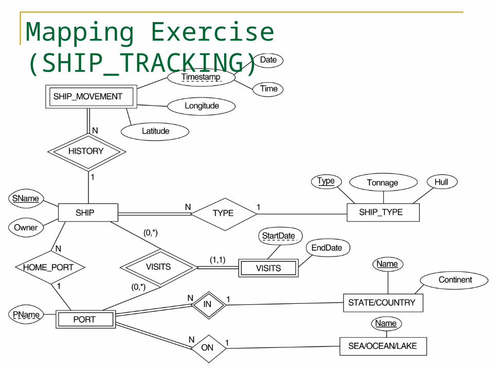
Mapping Exercise (SHIP_TRACKING)

63
Answer: SHIP(SName, Owner, Type, StateName, PName), PK:
SName, FK: Type references SHIP_TYPE, (StateName, PName) references PORT, Type: NOT NULL
SHIP_MOVEMENT(SName, Date, Time, Longitude, Latitude), PK: (SName, Date, Time), FK: SName references SHIP
SHIP_TYPE(Type, Tonnage, Hull), PK: Type STATE_COUNTRY(Name, Continent), PK: Name PORT(StateName, PName, Location), PK: (StateName,
PName), FK: StateName references STATE_COUNTRY, Location references SEA_OCEAN_LAKE
SEA_OCEAN_LAKE(Name), PK: Name VISITS(SName, StateName, PName, StartDate, EndDate),
PK: (SName, StateName, PName, StartDate), FK: SName references SHIP, (StateName, PName) references PORT