03ch075e rpt-泓格 i-7560, i-7561, i-7563
TRANSCRIPT
Report No: 03CH075E
Page:1 of 54 Version:1.0
Test Report
Product Name : ICPCON CPU with Converter
Model No. : I-7560, I-7561, I-7563, I-7513, I-7551, I-7017R, I-7017C,
I-7018R, SG-3071, SG-3081, PW-3090-24S,
PW-3090-12S, PW-3090-5S, PW-3090-5D, PW-3090-15D,
I-7188E3D-232, I-7188E5D-485, I-7188E3-232,
I-7188E5-485, NS-108
Applicant : ICP DAS CO., LTD. Address :No. 111, Kuangfu N. Rd., Hukou Shiang, Hsinchu, Taiwan
303, R.O.C.
Date of Receipt : 2003/12/23 Date of Test : 2003/12/23 Report No. : 03CH075E
The test results relate only to the samples tested. The test report shall not be reproduced except in full without the written approval of QuieTek Corporation.
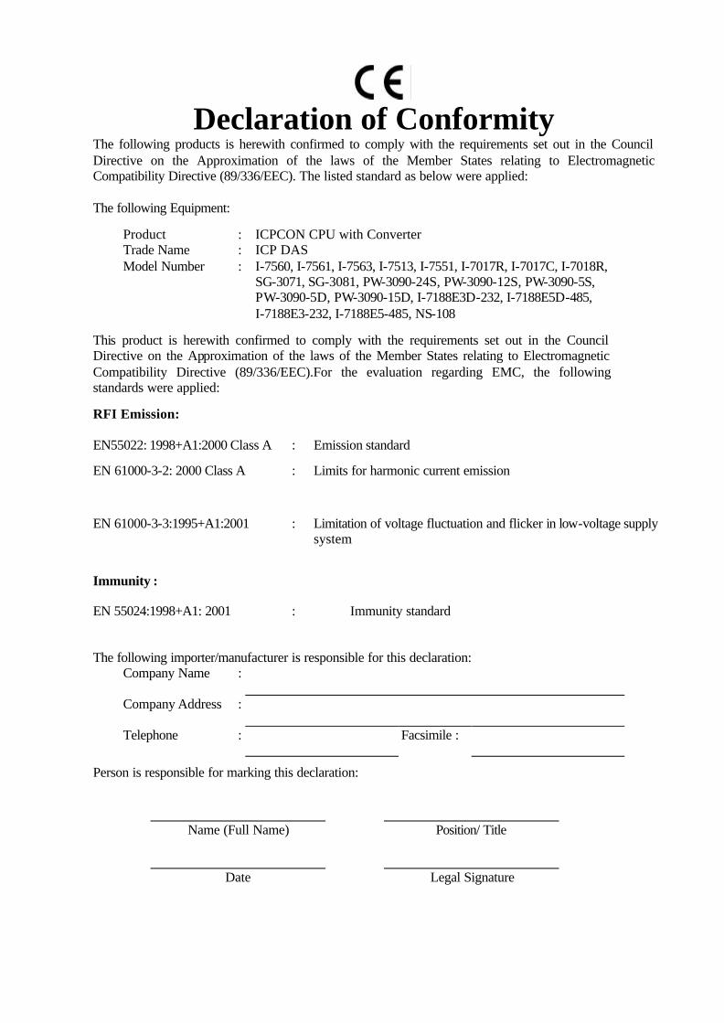
Declaration of Conformity
The following products is herewith confirmed to comply with the requirements set out in the Council Directive on the Approximation of the laws of the Member States relating to Electromagnetic Compatibility Directive (89/336/EEC). The listed standard as below were applied: The following Equipment:
Product : ICPCON CPU with Converter Trade Name : ICP DAS Model Number : I-7560, I-7561, I-7563, I-7513, I-7551, I-7017R, I-7017C, I-7018R,
SG-3071, SG-3081, PW-3090-24S, PW-3090-12S, PW-3090-5S, PW-3090-5D, PW-3090-15D, I-7188E3D-232, I-7188E5D-485, I-7188E3-232, I-7188E5-485, NS-108
This product is herewith confirmed to comply with the requirements set out in the Council Directive on the Approximation of the laws of the Member States relating to Electromagnetic Compatibility Directive (89/336/EEC).For the evaluation regarding EMC, the following standards were applied:
RFI Emission:
EN55022: 1998+A1:2000 Class A : Emission standard
EN 61000-3-2: 2000 Class A
: Limits for harmonic current emission
EN 61000-3-3:1995+A1:2001 : Limitation of voltage fluctuation and flicker in low-voltage supply system
Immunity :
EN 55024:1998+A1: 2001 : Immunity standard
The following importer/manufacturer is responsible for this declaration: Company Name :
Company Address :
Telephone : Facsimile :
Person is responsible for marking this declaration:
Name (Full Name) Position/ Title
Date Legal Signature

QuieTek Corporation / No.75-1, Wang-Yeh Valley, Yung-Hsing, Chiung-Lin, Hsin-Chu County, Taiwan, R.O.C. Tel: 886-3-5928858, Fax: 886-3-5928859, E-mail: [email protected]
Date: Dec. 24, 2003 QTK No.: 03CH075E
S t a t e m e n t o f C o n f o r m i t y
The certifies that the following designated product
Product : ICPCON CPU with Converter
Trade name : ICP DAS
Model Number : I-7560, I-7561, I-7563, I-7513, I-7551, I-7017R, I-7017C, I-7018R, SG-3071, SG-3081, PW-3090-24S, PW-3090-12S, PW-3090-5S, PW-3090-5D, PW-3090-15D, I-7188E3D-232, I-7188E5D-485, I-7188E3-232, I-7188E5-485, NS-108
Company Name : ICP DAS CO., LTD.
This product is herewith confirmed to comply with the requirements set out in the Council Directive on the Approximation of the laws of the Member States relating to Electromagnetic Compatibility Directive (89/336/EEC).For the evaluation regarding EMC, the following standards were applied:
RFI Emission:
EN55022: 1998+A1: 2000 Class B : Emission standard
EN 61000-3-2: 2000 Class A
: Limits for harmonic current emission
EN 61000-3-3:1995+A1:2001 : Limitation of voltage fluctuation and flicker in low-voltage supply system
Immunity :
EN 55024:1998+A1: 2001 : Immunity standard
TEST LABORATORY
Kevin Wang / Vice President
The verification is based on a single evaluation of one sample of above-mentioned products. It does not imply an assessment of the whole production and does not permit the use of the test lab. Logo.
EMC/Safety Test Laboratory Accredited by DNV, TUV, Nemko and NVLAP

Report No: 03CH075E
Page:2 of 54 Version:1.0
Test Repor t Cer t i f icat ion Test Date : 2003/12/23 Report No. : 03CH075E
Product Name : ICPCON CPU with Converter Applicant : ICP DAS CO., LTD. Address : No. 111, Kuangfu N. Rd., Hukou Shiang, Hsinchu, Taiwan 303,
R.O.C. Manufacturer : ICP DAS CO., LTD. Model No. : I-7560, I-7561, I-7563, I-7513, I-7551, I-7017R, I-7017C, I-7018R,
SG-3071, SG-3081, PW-3090-24S, PW-3090-12S, PW-3090-5S, PW-3090-5D, PW-3090-15D, I-7188E3D-232, I-7188E5D-485, I-7188E3-232, I-7188E5-485, NS-108
Rated Voltage : AC 230 V / 50 Hz Trade Name : ICP DAS Measurement Standard : EN 55022:1998+A1:2000
EN 61000-3-2:2000,EN61000-3-3:1995+A1:2001, EN55024:1998+A1:2001
Measurement Procedure : EN 55022:1998+A1:2000, EN 61000-3-2:2000, EN 61000-3-3:1995+A1:2001, IEC 61000-4-2:1995, IEC 61000-4-3:1995, IEC 61000-4-4:1995, IEC 61000-4-5:1995, IEC 61000-4-6:1996, IEC 61000-4-8:1993, IEC 61000-4-11:1994
Classification : A Test Result : Complied
The test results relate only to the samples tested. The test report shall not be reproduced except in full without the written approval of QuieTek Corporation.
Documented By :
( J o y c e L i n )
Tested By :
( M a t e T s e n g )
Approved By :
( K e v i n W a n g )
Accredited by TUV, DNV, Nemko and NIST (NVLAP)
Report No: 03CH075E
Page:3 of 54 Version:1.0
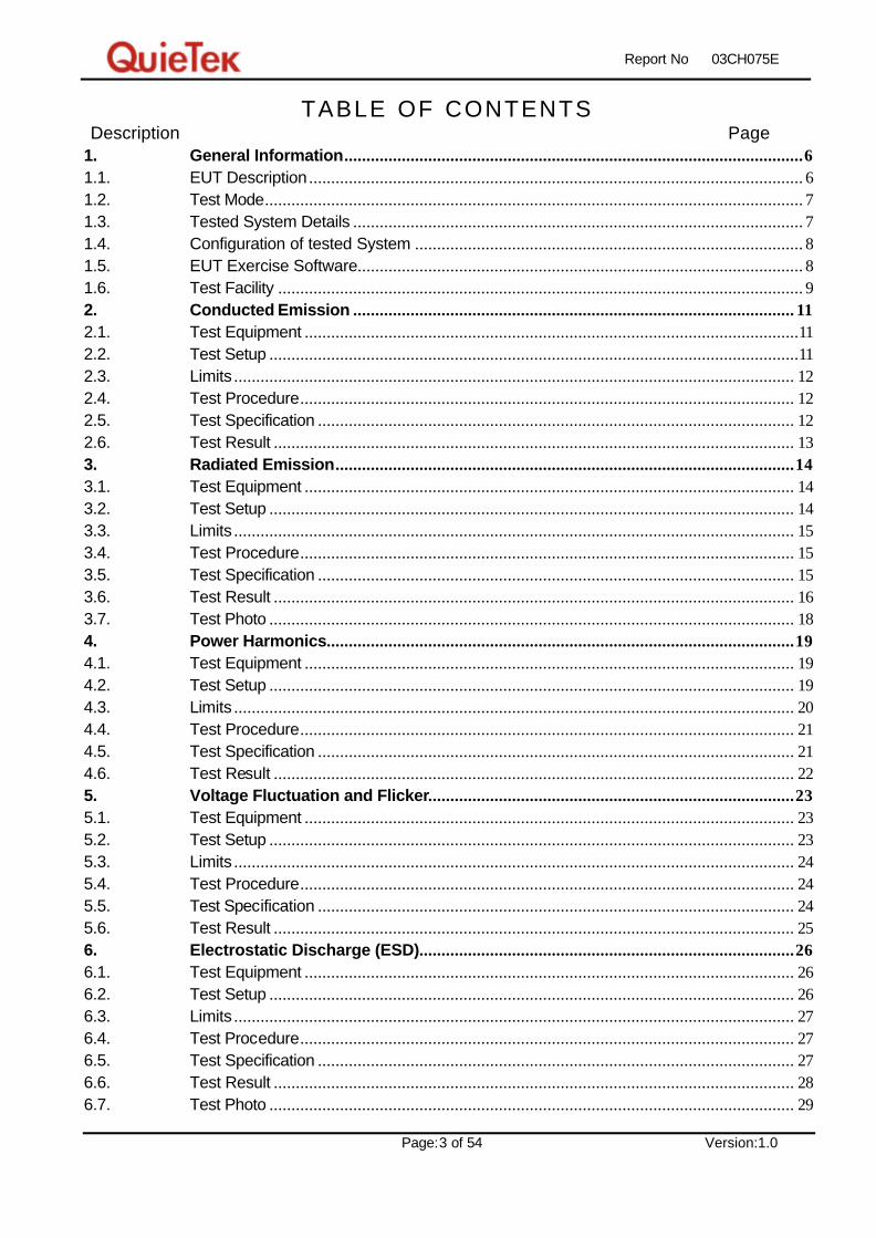
TABLE OF CONTENTS Description Page 1. General Information........................................................................................................6 1.1. EUT Description ................................................................................................................ 6 1.2. Test Mode.......................................................................................................................... 7 1.3. Tested System Details ...................................................................................................... 7 1.4. Configuration of tested System ........................................................................................ 8 1.5. EUT Exercise Software..................................................................................................... 8 1.6. Test Facility ....................................................................................................................... 9 2. Conducted Emission .................................................................................................... 11 2.1. Test Equipment ................................................................................................................11 2.2. Test Setup ........................................................................................................................11 2.3. Limits ............................................................................................................................... 12 2.4. Test Procedure................................................................................................................ 12 2.5. Test Specification ............................................................................................................ 12 2.6. Test Result ...................................................................................................................... 13 3. Radiated Emission........................................................................................................14 3.1. Test Equipment ............................................................................................................... 14 3.2. Test Setup ....................................................................................................................... 14 3.3. Limits ............................................................................................................................... 15 3.4. Test Procedure................................................................................................................ 15 3.5. Test Specification ............................................................................................................ 15 3.6. Test Result ...................................................................................................................... 16 3.7. Test Photo ....................................................................................................................... 18 4. Power Harmonics..........................................................................................................19 4.1. Test Equipment ............................................................................................................... 19 4.2. Test Setup ....................................................................................................................... 19 4.3. Limits ............................................................................................................................... 20 4.4. Test Procedure................................................................................................................ 21 4.5. Test Specification ............................................................................................................ 21 4.6. Test Result ...................................................................................................................... 22 5. Voltage Fluctuation and Flicker...................................................................................23 5.1. Test Equipment ............................................................................................................... 23 5.2. Test Setup ....................................................................................................................... 23 5.3. Limits ............................................................................................................................... 24 5.4. Test Procedure................................................................................................................ 24 5.5. Test Specification ............................................................................................................ 24 5.6. Test Result ...................................................................................................................... 25 6. Electrostatic Discharge (ESD).....................................................................................26 6.1. Test Equipment ............................................................................................................... 26 6.2. Test Setup ....................................................................................................................... 26 6.3. Limits ............................................................................................................................... 27 6.4. Test Procedure................................................................................................................ 27 6.5. Test Specification ............................................................................................................ 27 6.6. Test Result ...................................................................................................................... 28 6.7. Test Photo ....................................................................................................................... 29
Report No: 03CH075E
Page:4 of 54 Version:1.0
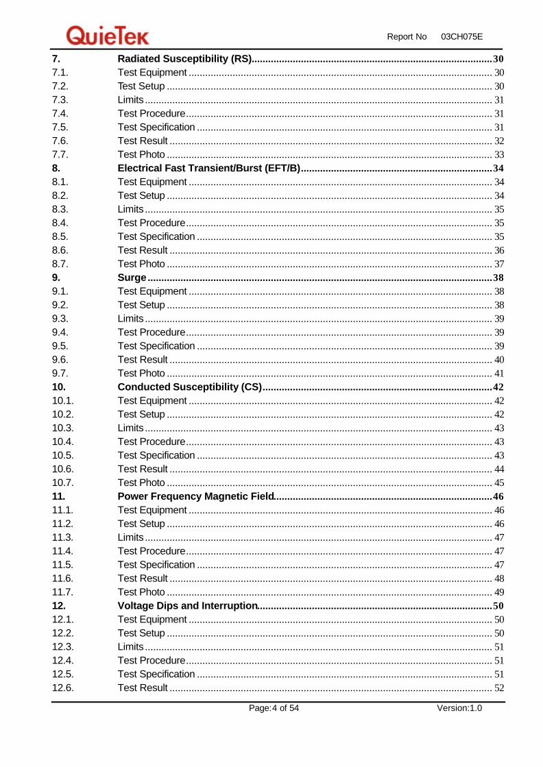
7. Radiated Susceptibility (RS)........................................................................................30 7.1. Test Equipment ............................................................................................................... 30 7.2. Test Setup ....................................................................................................................... 30 7.3. Limits ............................................................................................................................... 31 7.4. Test Procedure................................................................................................................ 31 7.5. Test Specification ............................................................................................................ 31 7.6. Test Result ...................................................................................................................... 32 7.7. Test Photo ....................................................................................................................... 33 8. Electrical Fast Transient/Burst (EFT/B)......................................................................34 8.1. Test Equipment ............................................................................................................... 34 8.2. Test Setup ....................................................................................................................... 34 8.3. Limits ............................................................................................................................... 35 8.4. Test Procedure................................................................................................................ 35 8.5. Test Specification ............................................................................................................ 35 8.6. Test Result ...................................................................................................................... 36 8.7. Test Photo ....................................................................................................................... 37 9. Surge ..............................................................................................................................38 9.1. Test Equipment ............................................................................................................... 38 9.2. Test Setup ....................................................................................................................... 38 9.3. Limits ............................................................................................................................... 39 9.4. Test Procedure................................................................................................................ 39 9.5. Test Specification ............................................................................................................ 39 9.6. Test Result ...................................................................................................................... 40 9.7. Test Photo ....................................................................................................................... 41 10. Conducted Susceptibility (CS)....................................................................................42 10.1. Test Equipment ............................................................................................................... 42 10.2. Test Setup ....................................................................................................................... 42 10.3. Limits ............................................................................................................................... 43 10.4. Test Procedure................................................................................................................ 43 10.5. Test Specification ............................................................................................................ 43 10.6. Test Result ...................................................................................................................... 44 10.7. Test Photo ....................................................................................................................... 45 11. Power Frequency Magnetic Field................................................................................46 11.1. Test Equipment ............................................................................................................... 46 11.2. Test Setup ....................................................................................................................... 46 11.3. Limits ............................................................................................................................... 47 11.4. Test Procedure................................................................................................................ 47 11.5. Test Specification ............................................................................................................ 47 11.6. Test Result ...................................................................................................................... 48 11.7. Test Photo ....................................................................................................................... 49 12. Voltage Dips and Interruption......................................................................................50 12.1. Test Equipment ............................................................................................................... 50 12.2. Test Setup ....................................................................................................................... 50 12.3. Limits ............................................................................................................................... 51 12.4. Test Procedure................................................................................................................ 51 12.5. Test Specification ............................................................................................................ 51 12.6. Test Result ...................................................................................................................... 52

Report No: 03CH075E
Page:5 of 54 Version:1.0
Attachement ............................................................................................................................................ 53 �� EUT Photograph ............................................................................................................. 53
Reference : Laboratory of License

Report No: 03CH075E
Page:6 of 54 Version:1.0
1. General Information
1.1. EUT Description
Product Name ICPCON CPU with Converter Trade Name ICP DAS Model No. I-7560, I-7561, I-7563, I-7513, I-7551, I-7017R, I-7017C, I-7018R,
SG-3071, SG-3081, PW-3090-24S, PW-3090-12S, PW-3090-5S, PW-3090-5D, PW-3090-15D, I-7188E3D-232, I-7188E5D-485, I-7188E3-232, I-7188E5-485, NS-108
EUT Voltage AC 230 V / 50 Hz
Component USB Cable Shielded, 1.2m, a ferrite core bonded. LAN Cable Non-Shielded, 1.4m, a ferrite core bonded.
Note:
1. Regarding to the different construction of the EUT, the model number were shown in the table as
following:
Model NO. Description
I-7560 USB to RS-232 Converter
I-7561 USB to RS-232/422/485 Converter
I-7563 USB to 3-channel RS-485 Converter Hub
I-7513 Three-way Isolated RS-485 to 3 port RS-485 Hub
I-7551 Isolated RS-232 to RS-232 Converter
I-7017R 8-channel Analog Input Module (Robust version)
I-7017C 8-channel Current input Module
I-7018R 8-channel Analog Input Module (Robust version)
I-7188E3-232 I-7188E3D-232 without LED display
I-7188E3D-232 Internet communication controller with two RS-232, one RS-485 and one Ethernet
I-7188E5-485 I-7188E5D-485 without LED display
I-7188E5D-485 Internet Communication Controller with one RS-232 , four RS-485 and one Ethernet
SG-3071 Isolated DC Voltage Input, Voltage / Current Output Module
SG-3081 Isolated DC Current Input, Voltage / Current Output Module
PW-3090-24S Isolated Power Supply Module, Output Power Voltage +24V
PW-3090-12S Isolated Power Supply Module, Output Power Voltage +12V
PW-3090-5S Isolated Power Supply Module, Output Power Voltage +5V
PW-3090-15D Isolated Power Supply Module, Output Power Voltage ±15V
PW-3090-5D Isolated Power Supply Module, Output Power Voltage ±5V
NS-108 Industrial Ethernet Switch Hub

Report No: 03CH075E
Page:7 of 54 Version:1.0
1.2. Test Mode
QuieTek has verified the construction and function in typical operation. All the test modes were
carried out with the EUT in normal operation, which was shown in this test report and defined
as:
Pre-Test Mode
EMC Normal operation
Final Test Mode
EMI Normal operation
EMS Normal operation
1.3. Tested System Details
The types for all equipments, plus descriptions of all cables used in the tested system
(including inserted cards) are:
Test Mode Normal operation Product Manufacturer Model No. Serial No. Power Cord
1 PC COMPAQ PD1100 SG30801006 Non-Shielded, 1.8m
2 Monitor VIEWSNOIC VCDT21490-1P ER01502850 Non-Shielded, 1.8m
3 Keyboard ACER 6311-TW4C/6 N/A --
4 Mouse HP M-S69 FbAB70S5B0S2SSK --
5 Printer HP C2642A MY75L1D2XN Non-Shielded, 0.7m
6 Modem ACEEX DM-1414 980033034 Non-Shielded, 1.6m
7 Microphone & Earphone
TOKTO SX-MI N/A --
8 Earphone KOKA CD-1200 N/A --
9 STEREO COMPACT DISC PLAYER
MIZDA CD-11 N/A --
10 Portable Hard DISK
FUJITSU MMA2200VB R129Y19003JC Non-Shielded, 1.8m
11 Portable Hard DISK
Top Disk Enterprise Me-910 217974 --
12 Portable Hard DISK
Top Disk Enterprise Me-910 217975 --
13 Portable Hard DISK
Top Disk Enterprise Me-910 220948 --
14 Portable Hard DISK
Top Disk Enterprise Me-910 220949 --

Report No: 03CH075E
Page:8 of 54 Version:1.0
1.4. Configuration of tested System
Test Mode Normal operation
Connection Diagram
Monitor(2)
STEREOCOMPACT DISC
PLAYER(9)
Keyboard(3)
PC(1)
Earphon(8)
EUT Printer(5)
PortableHard DISK
(10)
PortableHard DISK
(11)
PortableHard DISK
(12)
PortableHard DISK
(13)
PortableHard DISK
(14)
Mouse(4)
Modem(6)
Microphone& Earphone
(7)
A
B
C
DE
GH
I F
II
I I
JK
Signal Cable Type Signal cable Description
A VGA Cable Shielded, 1.6m, with one ferrite core bonded B Keyboard Cable Shielded, 1.8m C Mouse Cable Shielded, 1.8m D Printer Cable Shielded, 1.2m E Modem Cable Shielded, 1.5m F Earphone & Microphone Cable Non-Shielded, 1.2m G Earphone & Microphone Cable Non-Shielded, 1.2m H Walkman Cable Non-Shielded, 1.6m I USB Hard Disk Cable Shielded, 1.2m, five PCS. J LAN Cable Non-Shielded, 1.4m, with one ferrite core bonded K USB Cable Shielded, 1.2m, with one ferrite core bonded
1.5. EUT Exercise Software
Test Mode Normal operation 1 Setup the EUT and simulators as shown on 1.3. 2 Turn on the power of all equipment. 3 Boot the PC from Hard Disk. 4 Data will be communicated between computer and EUT. 5 The personal computer monitors’ will show the transmitting and receiving
characteristics when the communication is success. 6 Repeat the above procedure (4) to (5).
Report No: 03CH075E
Page:9 of 54 Version:1.0
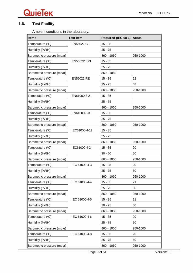
1.6. Test Facility
Ambient conditions in the laboratory:
Items Test Item Required (IEC 68-1) Actual
Temperature (°C) EN55022 CE 15 - 35
Humidity (%RH) 25 - 75
Barometric pressure (mbar) 860 - 1060 950-1000
Temperature (°C) EN55022 ISN 15 - 35
Humidity (%RH) 25 - 75
Barometric pressure (mbar) 860 - 1060
Temperature (°C) EN55022 RE 15 - 35 22
Humidity (%RH) 25 - 75 48
Barometric pressure (mbar) 860 - 1060 950-1000
Temperature (°C) EN61000-3-2 15 - 35
Humidity (%RH) 25 - 75
Barometric pressure (mbar) 860 - 1060 950-1000
Temperature (°C) EN61000-3-3 15 - 35
Humidity (%RH) 25 - 75
Barometric pressure (mbar) 860 - 1060 950-1000
Temperature (°C) IEC61000-4-11 15 - 35
Humidity (%RH) 25 - 75
Barometric pressure (mbar) 860 - 1060 950-1000
Temperature (°C) IEC61000-4-2 15 - 35 20
Humidity (%RH) 30 - 60 50
Barometric pressure (mbar) 860 - 1060 950-1000
Temperature (°C) IEC 61000-4-3 15 - 35 20
Humidity (%RH) 25 - 75 50
Barometric pressure (mbar) 860 - 1060 950-1000
Temperature (°C) IEC 61000-4-4 15 - 35 21
Humidity (%RH) 25 - 75 50
Barometric pressure (mbar) 860 - 1060 950-1000
Temperature (°C) IEC 61000-4-5 15 - 35 21
Humidity (%RH) 10 - 75 50
Barometric pressure (mbar) 860 - 1060 950-1000
Temperature (°C) IEC 61000-4-6 15 - 35 20
Humidity (%RH) 25 - 75 50
Barometric pressure (mbar) 860 - 1060 950-1000
Temperature (°C) IEC 61000-4-8 15 - 35 20
Humidity (%RH) 25 - 75 50
Barometric pressure (mbar) 860 - 1060 950-1000

Report No: 03CH075E
Page:10 of 54 Version:1.0
Site Description:
September 30, 2003 Accreditation on NVLAP
NVLAP Lab Code: 200347-0
February 23, 1999 Accreditation on DNV
Statement No. : 413-99-LAB11
January 04, 1999 Accreditation on TUV Rheinland
Certificate No.: I9865712-9901
October 08, 2003 Accreditation on Nemko
Certificate No.: ELA 165
Site Name: Quietek Corporation
Site Address: No.75-1, Wang-Yeh Valley, Yung-Hsing,
Chiung-Lin, Hsin-Chu County,
Taiwan, R.O.C.
TEL : 886-3-5928858 / FAX : 886-3-5928859 E-Mail : [email protected]
Report No: 03CH075E
Page:11 of 54 Version:1.0
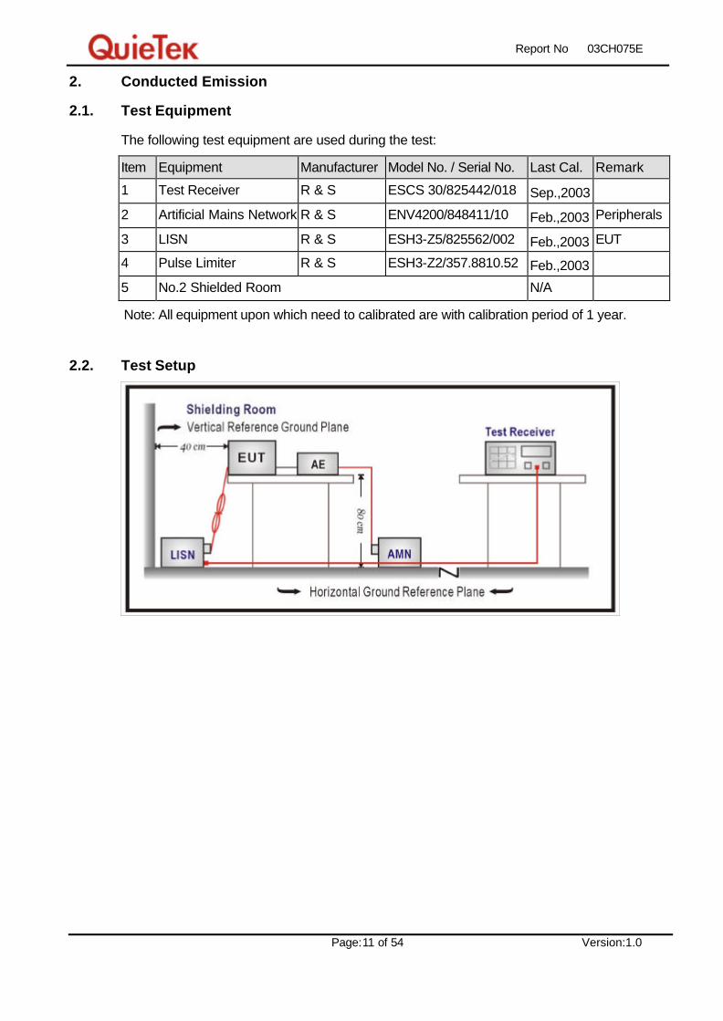
2. Conducted Emission
2.1. Test Equipment
The following test equipment are used during the test:
Item Equipment Manufacturer Model No. / Serial No. Last Cal. Remark
1 Test Receiver R & S ESCS 30/825442/018 Sep.,2003
2 Artificial Mains Network R & S ENV4200/848411/10 Feb.,2003 Peripherals
3 LISN R & S ESH3-Z5/825562/002 Feb.,2003 EUT
4 Pulse Limiter R & S ESH3-Z2/357.8810.52 Feb.,2003
5 No.2 Shielded Room N/A
Note: All equipment upon which need to calibrated are with calibration period of 1 year.
2.2. Test Setup

Report No: 03CH075E
Page:12 of 54 Version:1.0
2.3. Limits
EN 55022 Limits (dBuV)
Class A Class B Frequency
MHz QP AV QP AV
0.15 - 0.50 79 66 66-56 56-46
0.50-5.0 73 60 56 46
5.0 - 30 73 60 60 50
Remarks : In the above table, the tighter limit applies at the band edges.
2.4. Test Procedure
The EUT and simulators are connected to the main power through a line impedance
stabilization network (L.I.S.N.). This provides a 50 ohm /50uH coupling impedance for the
measuring equipment. The peripheral devices are also connected to the main power
through a LISN that provides a 50ohm/50uH coupling impedance with 50ohm termination.
(Please refers to the block diagram of the test setup and photographs.)
Both sides of A.C. line are checked for maximum conducted interference. In order to find
the maximum emission, the relative positions of equipment and all of the interface cables
must be changed according to EN 55022: 1998+A1: 2000 on conducted measurement.
Conducted emissions were invested over the frequency range from 0.15MHz to 30MHz
using a receiver bandwidth of 9kHz.
2.5. Test Specification
According to EN 55022: 1998+A1: 2000

Report No: 03CH075E
Page:13 of 54 Version:1.0
2.6. Test Result
Product ICPCON CPU with Converter Test Mode Normal operation Date of Test 2003/12/23 Test Site SR2 Test Condition Line1 Test Range 0.15~30MHz
Owing to the DC operation of EUT, this test item is not performed.

Report No: 03CH075E
Page:14 of 54 Version:1.0
3. Radiated Emission
3.1. Test Equipment
The following test equipment are used during the test:
Item Equipment Manufacturer Model No. / Serial No. Last Cal.
1 X Test Receiver R & S ESCS 30 / 836858/023 Jan.,2003
2 X Spectrum Analyzer Advantest R3261C / 81720471 N/A
3 X Pre-Amplifier QuieTek QTK-AMP / AMP1 N/A
4 X Bilog Antenna Chase CBL6112B / 2708 Sep.,2003
5 No.2 OATS Sep.,2003
Note: 1. All equipments that need to calibrate are with calibration period of 1 year. 2. Mark “X” test instruments are used to measure the final test results.
3.2. Test Setup

Report No: 03CH075E
Page:15 of 54 Version:1.0
3.3. Limits
EN 55022 Limits (dBuV/m)
Class A Class B Frequency
MHz Distance
(m) dBuV/m Distance
(m) dBuV/m
30 – 230 10 40 10 30
230 – 1000 10 47 10 37
Remark: 1. The tighter limit shall apply at the edge between two frequency bands.
2. Distance refers to the distance in meters between the measuring
instrument antenna and the closed point of any part of the device or
system.
3. RF Voltage (dBuV/m) = 20 log RF Voltage (uV/m)
3.4. Test Procedure
The EUT and its simulators are placed on a turn table which is 0.8 meter above ground.
The turn table can rotate 360 degrees to determine the position of the maximum emission
level. The EUT was positioned such that the distance from antenna to the EUT was 10
meters.
The antenna can move up and down between 1 meter and 4 meters to find out the
maximum emission level.
All cable leaving the table-top EUT for a connection outsidethe test site (for example, mains
cable, telephone lines, connections to auxiliary equipment located outside the test area) shall
be fitted with ferrite clamps placed on the floor at the point where the cable reached the floor.
Both horizontal and vertical polarization of the antenna are set on measurement. In order
to find the maximum emission, all of the interface cables must be manipulated according
to EN 55022: 1998+A1: 2000 on radiated measurement.
Radiated emissions were invested over the frequency range from 30MHz to1GHz using a
receiver bandwidth of 120kHz. Radiated was performed at an antenna to EUT distance of
10 meters.
3.5. Test Specification
According to EN 55022: 1998+A1: 2000

Report No: 03CH075E
Page:16 of 54 Version:1.0
3.6. Test Result
Product ICPCON CPU with Converter Test Mode Normal operation Date of Test 2003/12/23 Test Site Site2 Test Condition Horizontal Test Range 30~1000MHz
Frequency Cable Probe PreAMP Reading Emission Margin Limit
Loss Factor Level Level
MHz dB dB/m dB dBuV dBuV/m dB dBuV/m
==========================================================
Horizontal:
43.325 1.28 11.49 0.00 7.00 19.77 20.23 40.00
66.000 1.50 6.16 0.00 11.78 19.44 20.56 40.00
125.000 2.07 11.84 0.00 9.99 23.90 16.10 40.00
200.025 2.78 9.30 0.00 9.99 22.07 17.93 40.00
250.025 3.27 12.61 0.00 9.42 25.30 21.70 47.00
360.025 4.07 14.70 0.00 4.16 22.93 24.07 47.00
* 500.045 4.79 17.34 0.00 10.15 32.28 14.72 47.00
625.045 5.44 19.30 0.00 3.54 28.29 18.71 47.00
Note:
1. All Reading Levels are Quasi-Peak value.
2. “ * ”, means this data is the worst emission level.
3. Emission Level = Reading Level + Probe Factor + Cable Loss.
Report No: 03CH075E
Page:17 of 54 Version:1.0
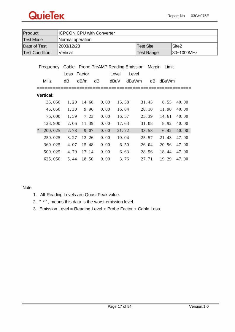
Product ICPCON CPU with Converter Test Mode Normal operation Date of Test 2003/12/23 Test Site Site2 Test Condition Vertical Test Range 30~1000MHz
Frequency Cable Probe PreAMP Reading Emission Margin Limit
Loss Factor Level Level
MHz dB dB/m dB dBuV dBuV/m dB dBuV/m
==========================================================
Vertical:
35.050 1.20 14.68 0.00 15.58 31.45 8.55 40.00
45.050 1.30 9.96 0.00 16.84 28.10 11.90 40.00
76.000 1.59 7.23 0.00 16.57 25.39 14.61 40.00
123.900 2.06 11.39 0.00 17.63 31.08 8.92 40.00
* 200.025 2.78 9.07 0.00 21.72 33.58 6.42 40.00
250.025 3.27 12.26 0.00 10.04 25.57 21.43 47.00
360.025 4.07 15.48 0.00 6.50 26.04 20.96 47.00
500.025 4.79 17.14 0.00 6.63 28.56 18.44 47.00
625.050 5.44 18.50 0.00 3.76 27.71 19.29 47.00
Note:
1. All Reading Levels are Quasi-Peak value.
2. “ * ”, means this data is the worst emission level.
3. Emission Level = Reading Level + Probe Factor + Cable Loss.

Report No: 03CH075E
Page:18 of 54 Version:1.0
3.7. Test Photo
Test Mode : Normal operation Description: Front View of Radiated Test
Test Mode : Normal operation Description: Back View of Radiated Test

Report No: 03CH075E
Page:19 of 54 Version:1.0
4. Power Harmonics
4.1. Test Equipment
The following test equipment are used during the test: Item Equipment Manufacturer Model No. / Serial No. Last Cal.
1 Power Frequency Test System HAEFELY PHF-555 / 080 419-29 Apr.,2003
2 No.1 Shielded Room N/A
Note: All equipment upon which need to calibrated are with calibration period of 1 year.
4.2. Test Setup

Report No: 03CH075E
Page:20 of 54 Version:1.0
4.3. Limits
ØLimits of Class A Harmonics Currents
Harmonics Order
n
Maximum Permissible harmonic current
A
Harmonics Order
n
Maximum Permissible harmonic current
A
Odd harmonics Even harmonics
3 2.30 2 1.08
5 1.14 4 0.43
7 0.77 6 0.30
9 0.40 8 ≤ n ≤ 40 0.23 * 8/n
11 0.33
13 0.21
15 ≤ n ≤ 39 0.15 * 15/n
ØLimits of Class B Harmonics Currents
For Class B equipment, the harmonic of the input current shall not exceed the maximum
permissible values given in table that is the limit of Class A multiplied by a factor of 1.5.
ØLimits of Class C Harmonics Currents
Harmonics Order n
Maximum Permissible harmonic current Expressed as a percentage of the input current at the fundamental frequency
%
2 2
3 30.?*
5 10
7 7
9 5
11 ≤ n ≤ 39
(odd harmonics only) 3
*? is the circuit power factor

Report No: 03CH075E
Page:21 of 54 Version:1.0
ØLimits of Class D Harmonics Currents
Harmonics Order n
Maximum Permissible harmonic current per watt
mA/W
Maximum Permissible harmonic current
A
3 3.4 2.30
5 1.9 1.14
7 1.0 0.77
9 0.5 0.40
11 0.35 0.33
11 ≤ n ≤ 39
(odd harmonics only) 3.85/n See limit of Class A
4.4. Test Procedure
The EUT is supplied in series with power analyzer from a power source having the same
normal voltage and frequency as the rated supply voltage and the equipment under test.
And the rated voltage at the supply voltage of EUT of 0.94 times and 1.06 times shall be
performed.
4.5. Test Specification
According to EN 61000-3-2: 2000

Report No: 03CH075E
Page:22 of 54 Version:1.0
4.6. Test Result
Product ICPCON CPU with Converter Test Mode Normal operation Date of Test 2003/12/23 Test Site SR1 Test Condition Power Harmonics Test Range
Owing to the DC operation of EUT, this test item is not performed.

Report No: 03CH075E
Page:23 of 54 Version:1.0
5. Voltage Fluctuation and Flicker
5.1. Test Equipment
The following test equipment are used during the test: Item Equipment Manufacturer Model No. / Serial No. Last Cal.
1 Power Frequency Test System HAEFELY PHF-555 / 080 419-29 Apr.,2003
2 No.1 Shielded Room N/A
Note: All equipment upon which need to calibrated are with calibration period of 1 year.
5.2. Test Setup
Report No: 03CH075E
Page:24 of 54 Version:1.0
5.3. Limits
The following limits apply:
- the value of Pst shall not be greater than 1.0;
- the value of P1t shall not be greater than 0.65;
- the value of d(t) during a voltage change shall not exceed 3.3 % for more than 500 ms;
- the relative steady-state voltage change, dc, shall not exceed 3.3 %;
- the maximum relative voltage change, dmax, shall not exceed;
a) 4 % without additional conditions;
b) 6 % for equipment which is:
- switched manually, or
- switched automatically more frequently than twice per day, and also has either a
delayed restart (the delay being not less than a few tens of seconds), or manual restart,
after a power supply interruption.
NOTE The cycling frequency will be further limited by the Pst and P1t limit. For example: a dmax
of 6%producing a rectangular voltage change characteristic twice per hour will give a
P1t of about 0.65.
c) 7 % for equipment which is:
- attended whilst in use (for example: hair dryers, vacuum cleaners, kitchen equipment
such as mixers, garden equipment such as lawn mowers, portable tools such as electric
drills), or
- switched on automatically, or is intended to be switched on manually, no more than
twice per day, and also has either a delayed restart (the delay being not less than a few
tens of seconds) or manual restart, after a power supply interruption.
Pst and P1t requirements shall not be applied to voltage changes caused by manual
switching.
5.4. Test Procedure
The EUT is supplied in series with power analyzer from a power source having the same
normal voltage and frequency as the rated supply voltage and the equipment under test.
And the rated voltage at the supply voltage of EUT of 0.94 times and 1.06 times shall be
performed.
5.5. Test Specification
According to EN 61000-3-3:1995+A1:2001

Report No: 03CH075E
Page:25 of 54 Version:1.0
5.6. Test Result
Product ICPCON CPU with Converter Test Mode Normal operation Date of Test 2003/12/23 Test Site SR1 Test Condition Flicker Test Range
Owing to the DC operation of EUT, this test item is not performed.

Report No: 03CH075E
Page:26 of 54 Version:1.0
6. Electrostatic Discharge (ESD)
6.1. Test Equipment
The following test equipment are used during the test: Item Equipment Manufacturer Model No. / Serial No. Last Cal.
1 EM TEST EM UCS 500-M / UCS500M4 Jan.,2003
2 Electrostatic Discharge EM P18 / 1198-34 Jan.,2003
3 Horizontal Coupling Plane(HCP)
QuieTek HCP AL50 N/A
4 Vertical Coupling Plane(VCP)
QuieTek VCP AL50 N/A
5 No.1 Shielded Room N/A
Note: All equipment upon which need to calibrated are with calibration period of 1 year.
6.2. Test Setup

Report No: 03CH075E
Page:27 of 54 Version:1.0
6.3. Limits
Item Environmental Phenomena Units Test Specification Performance Criteria
Enclosure Port
Electrostatic Discharge kV(Charge Voltage) ±8 Air Discharge
±4 Contact Discharge
B
6.4. Test Procedure
Direct application of discharges to the EUT:
Contact discharge was applied only to conductive surfaces of the EUT.
Air discharges were applied only to non-conductive surfaces of the EUT.
During the test, it was performed with single discharges. For the single discharge
time between successive single discharges will be keep longer 1 second. It was at
least ten single discharges with positive and negative at the same selected point.
The selected point, which was performed with electrostatic discharge, was marked
on the red label of the EUT.
Indirect application of discharges to the EUT:
Vertical Coupling Plane (VCP):
The coupling plane, of dimensions 0.5m x 0.5m, is placed parallel to, and positioned
at a distance 0.1m from, the EUT, with the Discharge Electrode touching the
coupling plane.
The four faces of the EUT will be performed with electrostatic discharge. It was at
least ten single discharges with positive and negative at the same selected point.
Horizontal Coupling Plane (HCP):
The coupling plane is placed under to the EUT. The generator shall be positioned
vertically at a distance of 0.1m from the EUT, with the Discharge Electrode touching
the coupling plane.
The four faces of the EUT will be performed with electrostatic discharge. It was at
least ten single discharges with positive and negative at the same selected point.
6.5. Test Specification
According to IEC 61000-4-2: 1995

Report No: 03CH075E
Page:28 of 54 Version:1.0
6.6. Test Result
Product ICPCON CPU with Converter Test Mode Normal operation Date of Test 2003/12/23 Test Site SR1 Test Condition ESD Test Range
Item Amount of
Discharge Voltage
Required
Criteria
Complied To
Criteria (A,B,C) Results
Air Discharge 10
10
+8kV
-8kV
B
B
A
A
Pass
Pass
Contact Discharge 10
10
+4kV
-4kV
B
B
A
A
Pass
Pass
Indirect Discharge
(HCP)
50
50
+4kV
-4kV
B
B
A
A
Pass
Pass
Indirect Discharge
(VCP Front)
50
50
+4kV
-4kV
B
B
A
A
Pass
Pass
Indirect Discharge
(VCP Left)
50
50
+4kV
-4kV
B
B
A
A
Pass
Pass
Indirect Discharge
(VCP Back)
50
50
+4kV
-4kV
B
B
A
A
Pass
Pass
Indirect Discharge
(VCP Right)
50
50
+4kV
-4kV
B
B
A
A
Pass
Pass
NR: No Requirement
Meet criteria A: Operate as intended during and after the test
Meet criteria B: Operate as intended after the test
Meet criteria C: Loss/Error of function
Additional Information
EUT stopped operation and could / could not be reset by operator at kV.
No false alarms or other malfunctions were observed during or after the test.
Remark:
The Contact discharges were applied-at least total 200 discharges at a minimum of four test points.

Report No: 03CH075E
Page:29 of 54 Version:1.0
6.7. Test Photo
Test Mode : Normal operation Description: ESD Test Setup

Report No: 03CH075E
Page:30 of 54 Version:1.0
7. Radiated Susceptibility (RS)
7.1. Test Equipment
The following test equipment are used during the test: Item Equipment Manufacturer Model No. / Serial No. Last Cal.
1 Signal Generator R & S SYM02 / 825454/029 Jan.,2003
2 Power Amplifier A & R 100W10000M7 / A285000010
N/A
3 RF Power Amplifier OPHIRRF 5022F / 1075 N/A
4 Bilog Antenna Chase CBL6112B / 2452 Sep.,2003
5 Power Meter R & S NRVD / 100219 Sep.,2003
6 Directional Coupler A & R DC6180 / 22735 Feb.,2003
7 No.4 EMC Fully Chamber Jul.,2003
Note: All equipment upon which need to calibrated are with calibration period of 1 year.
7.2. Test Setup

Report No: 03CH075E
Page:31 of 54 Version:1.0
7.3. Limits
Item Environmental Phenomena Units Test Specification Performance Criteria
Enclosure Port Radio-Frequency
Electromagnetic Field
Amplitude Modulated
MHz
V/m(Un-modulated, rms)
% AM (1kHz)
80-1000
3
80
A
7.4. Test Procedure
The EUT and load, which are placed on a table that is 0.8 meter above ground, are
placed with one coincident with the calibration plane such that the distance from antenna
to the EUT was 3 meters.
Both horizontal and vertical polarization of the antenna and four sides of the EUT are set
on measurement.
In order to judge the EUT performance, a CCD camera is used to monitor EUT screen.
All the scanning conditions are as follows:
Condition of Test Remarks
1. Field Strength 3 V/m Level 2
2. Radiated Signal AM 80% Modulated with 1kHz
3. Scanning Frequency 80MHz - 1000MHz
4 Dwell Time 3 Seconds
5. Frequency step size ∆ f : 1%
6. The rate of Swept of Frequency 1.5 x 10⁻³ decades/s
7.5. Test Specification
According to IEC 61000-4-3: 1995

Report No: 03CH075E
Page:32 of 54 Version:1.0
7.6. Test Result
Product ICPCON CPU with Converter Test Mode Normal operation Date of Test 2003/12/23 Test Site Chamber4 Test Condition RS Test Range 80~1000
Frequency
(MHz)
Position
(Angle)
Polarity
(H or V)
Field
Strength
(V/m)
Required
Criteria
Complied To
Criteria
(A,B,C)
Results
80-1000 0 H 3 A A Pass
80-1000 0 V 3 A A Pass
80-1000 90 H 3 A A Pass
80-1000 90 V 3 A A Pass
80-1000 180 H 3 A A Pass
80-1000 180 V 3 A A Pass
80-1000 270 H 3 A A Pass
80-1000 270 V 3 A A Pass
Meet criteria A : Operate as intended during and after the test
Meet criteria B : Operate as intended after the test
Meet criteria C : Loss/Error of function
Additional Information
EUT stopped operation and could / could not be reset by operator at V/m at frequency
MHz.
No false alarms or other malfunctions were observed during or after the test. The acceptance
criteria were met, and the EUT passed the test.

Report No: 03CH075E
Page:33 of 54 Version:1.0
7.7. Test Photo
Test Mode : Normal operation Description: Radiated Susceptibility Test Setup

Report No: 03CH075E
Page:34 of 54 Version:1.0
8. Electrical Fast Transient/Burst (EFT/B)
8.1. Test Equipment
The following test equipment are used during the test: Item Equipment Manufacturer Model No. / Serial No. Last Cal.
1 EM TEST EM UCS 500-M / UCS500M4 Jan.,2003
2 Clamp HAEFELY 093 506.1 / 083 593-23 Jan.,2003
3 No.1 Shielded Room N/A
Note: All equipment upon which need to calibrated are with calibration period of 1 year.
8.2. Test Setup

Report No: 03CH075E
Page:35 of 54 Version:1.0
8.3. Limits
Item Environmental Phenomena Units Test Specification Performance Criteria
Signal Ports and Telecommunication Ports
Fast Transients Common
Mode
kV (Peak)
Tr/Th ns
Rep. Frequency kHz
+0.5
5/50
5
B
Input DC Power Ports
Fast Transients Common
Mode
kV (Peak)
Tr/Th ns
Rep. Frequency kHz
+0.5
5/50
5
B
Input AC Power Ports
Fast Transients Common
Mode
kV (Peak)
Tr/Th ns
Rep. Frequency kHz
+1
5/50
5
B
8.4. Test Procedure
The EUT and load are placed on a table that is 0.8 meter above a metal ground plane
measured 1m*1m min. and 0.65mm thick min. And projected beyond the EUT by at least
0.1m on all sides.
For Signal Ports and Telecommunication Ports:
The EFT interference signal is through a coupling clamp device couples to the signal
and control lines of the EUT with burst noise for 1min.
For Input DC and AC Power Ports:
The EUT is connected to the power mains through a coupling device that directly
couples the EFT interference signal.
Each of the Line and Neutral conductors is impressed with burst noise for 1 min.
The length of power cord between the coupling device and the EUT shall be 1m.
8.5. Test Specification
According to IEC 61000-4-4: 1995

Report No: 03CH075E
Page:36 of 54 Version:1.0
8.6. Test Result
Product ICPCON CPU with Converter Test Mode Normal operation Date of Test 2003/12/23 Test Site SR1 Test Condition EFT/B Test Range
Inject
Line Polarity
Voltage
kV
Inject
Time
(Second)
Inject
Method
Required
Criteria
Complied to
Criteria Result
L ± 1kV 60 Direct B A Pass
N ± 1kV 60 Direct B A Pass
L+N ± 1kV 60 Direct B A Pass
Meet criteria A : Operate as intended during and after the test
Meet criteria B : Operate as intended after the test
Meet criteria C : Loss/Error of function
Additional Information
EUT stopped operation and could / could not be reset by operator at kV of
Line .
No false alarms or other malfunctions were observed during or after the test.
Report No: 03CH075E
Page:37 of 54 Version:1.0
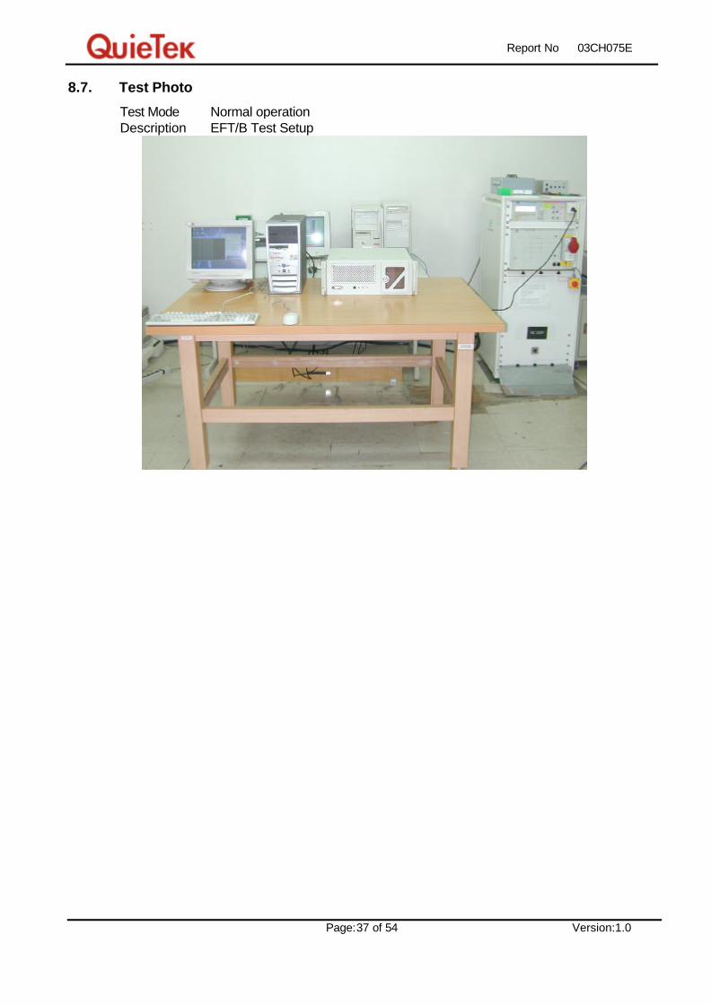
8.7. Test Photo
Test Mode : Normal operation Description: EFT/B Test Setup
Report No: 03CH075E
Page:38 of 54 Version:1.0
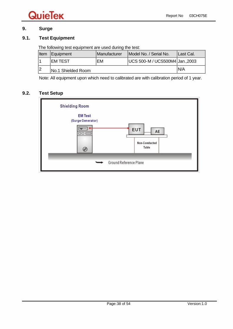
9. Surge
9.1. Test Equipment
The following test equipment are used during the test: Item Equipment Manufacturer Model No. / Serial No. Last Cal.
1 EM TEST EM UCS 500-M / UCS500M4 Jan.,2003
2 No.1 Shielded Room N/A
Note: All equipment upon which need to calibrated are with calibration period of 1 year.
9.2. Test Setup
Report No: 03CH075E
Page:39 of 54 Version:1.0
9.3. Limits
Item Environmental Phenomena Units Test Specification Performance Criteria
Signal Ports and Telecommunication Ports(See 1) and 2) )
Surges
Line to Ground
Tr/Th us
kV
1.2/50 (8/20)
± 1
B
Input DC Power Ports
Surges
Line to Ground
Tr/Th us
kV
1.2/50 (8/20)
± 0.5
B
AC Input and AC Output Power Ports
Surges
Line to Line
Line to Ground
Tr/Th us
kV
kV
1.2/50 (8/20)
± 1
± 2
B
Notes:
1) Applicable only to ports which according to the manufacturer’s may directly to outdoor
cables.
2) Where normal functioning cannot be achieved because of the impact of the CDN on the EUT,
no immunity test shall be required.
9.4. Test Procedure
The EUT and its load are placed on a table that is 0.8 meter above a metal ground plane
measured 1m*1m min. and 0.65mm thick min. And projected beyond the EUT by at least 0.1m
on all sides. The length of power cord between the coupling device and the EUT shall be 2m
or less.
For Input and Output AC Power or DC Input and DC Output Power Ports:
The EUT is connected to the power mains through a coupling device that directly couples
the Surge interference signal.
The surge noise shall be applied synchronized to the voltage phase at 00, 900, 1800, 2700
and the peak value of the a.c. voltage wave. (Positive and negative)
Each of Line-Earth and Line-Line is impressed with a sequence of five surge voltages with
interval of 1 min.
9.5. Test Specification
According to IEC 61000-4-5: 1995
Report No: 03CH075E
Page:40 of 54 Version:1.0
9.6. Test Result
Product ICPCON CPU with Converter Test Mode Normal operation Date of Test 2003/12/23 Test Site SR1 Test Condition Surge Test Range
Inject
Line Polarity Angle
Voltage
kV
Time
Interval
(Second)
Inject
Method
Required
Criteria
Complied
to
Criteria
Result
L-N ± 90 1kV 60 Direct B A Pass
L-N ± 90 1kV 60 Direct B A Pass
L-N ± 180 1kV 60 Direct B A Pass
L-N ± 270 1kV 60 Direct B A Pass
Meet criteria A : Operate as intended during and after the test
Meet criteria B : Operate as intended after the test
Meet criteria C : Loss/Error of function
Additional Information
EUT stopped operation and could / could not be reset by operator at kV of
Line .
No false alarms or other malfunctions were observed during or after the test.

Report No: 03CH075E
Page:41 of 54 Version:1.0
9.7. Test Photo
Test Mode : Normal operation Description: SURGE Test Setup

Report No: 03CH075E
Page:42 of 54 Version:1.0
10. Conducted Susceptibility (CS)
10.1. Test Equipment
The following test equipment are used during the test: Item Equipment Manufacturer Model No. / Serial No. Last Cal.
1 Signal Generator R & S SYM01 / 10065 Jan.,2003
2 Power Amplifier A & R 150A220 / 23076 N/A
3 Power Meter HP EPM-4418A / GB37482040 Feb.,2003
4 Power Sensor Agilent 8482A / MY41091031 Aug.,2003
5 Directional Coupler A & R DC2600 / 23325 Feb.,2003
6 CDN Lüthi CDN L-801 M1 / 2047 Jun.,2003
7 CDN Lüthi CDN L-801 M2/M3 / 2043 Jun.,2003
8 FIXED PAD TRILITHIC HFP-525-3/6-NF/NF / N/A N/A
9 EM Clamp Lüthi EM101 / 3552C Apr.,2003
10 No.5 Shielded Room N/A
Note: All equipment upon which need to calibrated are with calibration period of 1 year.
10.2. Test Setup

Report No: 03CH075E
Page:43 of 54 Version:1.0
10.3. Limits
Item Environmental Phenomena Units Test Specification Performance Criteria
Signal Ports and Telecommunication Ports
Radio-Frequency
Continuous Conducted
MHz
V (rms, Un-modulated)
% AM (1kHz)
0.15-80
3
80
A
Input DC Power Ports
Radio-Frequency
Continuous Conducted
MHz
V (rms, Un-modulated)
% AM (1kHz)
0.15-80
3
80
A
Input AC Power Ports
Radio-Frequency
Continuous Conducted
MHz
V (rms, Un-modulated)
% AM (1kHz)
0.15-80
3
80
A
10.4. Test Procedure
The EUT are placed on a table that is 0.8 meter height, and a Ground reference plane on
the table, EUT are placed upon table and use a 10cm insulation between the EUT and
Ground reference plane.
For Signal Ports and Telecommunication Ports
The disturbance signal is through a coupling and decoupling networks (CDN) or
EM-clamp device couples to the signal and Telecommunication lines of the EUT.
For Input DC and AC Power Ports
The EUT is connected to the power mains through a coupling and decoupling networks
for power supply lines. And directly couples the disturbances signal into EUT.
Used CDN-M2 for two wires or CDN-M3 for three wires.
All the scanning conditions are as follows:
Condition of Test Remarks
1. Field Strength 130dBuV(3V) Level 2
2. Radiated Signal AM 80% Modulated with 1kHz
3. Scanning Frequency 0.15MHz – 80MHz
4 Dwell Time 3 Seconds
5. Frequency step size ∆ f : 1%
6. The rate of Swept of Frequency 1.5 x 10⁻³ decades/s
10.5. Test Specification
According to IEC 61000-4-6: 1996
Report No: 03CH075E
Page:44 of 54 Version:1.0
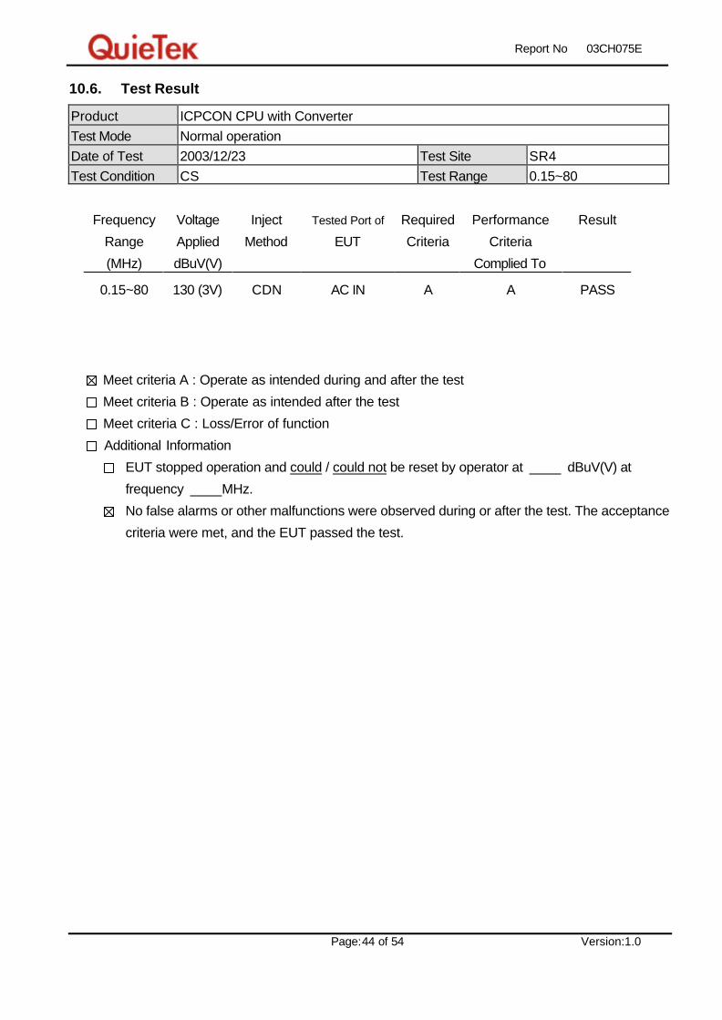
10.6. Test Result
Product ICPCON CPU with Converter Test Mode Normal operation Date of Test 2003/12/23 Test Site SR4 Test Condition CS Test Range 0.15~80
Frequency
Range
(MHz)
Voltage
Applied
dBuV(V)
Inject
Method
Tested Port of
EUT
Required
Criteria
Performance
Criteria
Complied To
Result
0.15~80 130 (3V) CDN AC IN A A PASS
Meet criteria A : Operate as intended during and after the test
Meet criteria B : Operate as intended after the test
Meet criteria C : Loss/Error of function
Additional Information
EUT stopped operation and could / could not be reset by operator at dBuV(V) at
frequency MHz.
No false alarms or other malfunctions were observed during or after the test. The acceptance
criteria were met, and the EUT passed the test.

Report No: 03CH075E
Page:45 of 54 Version:1.0
10.7. Test Photo
Test Mode : Normal operation Description: Conducted Susceptibility Test Setup
Report No: 03CH075E
Page:46 of 54 Version:1.0
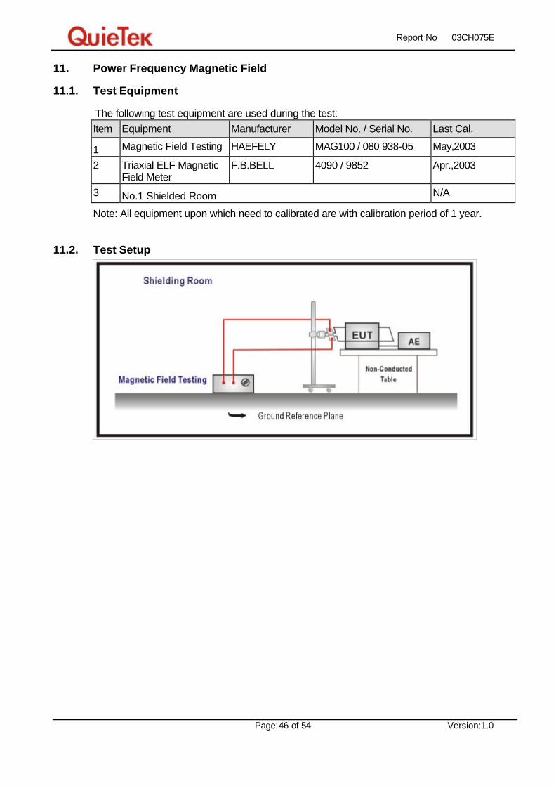
11. Power Frequency Magnetic Field
11.1. Test Equipment
The following test equipment are used during the test: Item Equipment Manufacturer Model No. / Serial No. Last Cal.
1 Magnetic Field Testing HAEFELY MAG100 / 080 938-05 May,2003
2 Triaxial ELF Magnetic Field Meter
F.B.BELL 4090 / 9852 Apr.,2003
3 No.1 Shielded Room N/A
Note: All equipment upon which need to calibrated are with calibration period of 1 year.
11.2. Test Setup

Report No: 03CH075E
Page:47 of 54 Version:1.0
11.3. Limits
Item Environmental Phenomena Units Test Specification Performance Criteria
Enclosure Port
Power-Frequency Magnetic Field
Hz A/m (r.m.s.)
50 1
A
11.4. Test Procedure
The EUT and its load are placed on a table which is 0.8 meter above a metal ground
plane measured at least 1m*1m min. The test magnetic field shall be placed at central of
the induction coil.
The test magnetic Field shall be applied 10minutes by the immersion method to the EUT.
And the induction coil shall be rotated by 90° in order to expose the EUT to the test field
with different orientation (X, Y, Z Orientations).
11.5. Test Specification
According to IEC 61000-4-8: 1993

Report No: 03CH075E
Page:48 of 54 Version:1.0
11.6. Test Result
Product ICPCON CPU with Converter Test Mode Normal operation Date of Test 2003/12/23 Test Site SR1 Test Condition PMag Test Range
Polarization Frequency
(Hz)
Magnetic
Strength
(A/m)
Required
Performance
Criteria
Performance
Criteria
Complied To
Test Result
X Orientation 50 1 A A PASS
Y Orientation 50 1 A A PASS
Z Orientation 50 1 A A PASS
Meet criteria A : Operate as intended during and after the test
Meet criteria B : Operate as intended after the test
Meet criteria C : Loss/Error of function
Additional Information
EUT stopped operation and could / could not be reset by operator at A/m.
No false alarms or other malfunctions were observed during or after the test. The acceptance
criteria were met, and the EUT passed the test.

Report No: 03CH075E
Page:49 of 54 Version:1.0
11.7. Test Photo
Test Mode : Normal operation Description: Power Frequency Magnetic Field Test Setup

Report No: 03CH075E
Page:50 of 54 Version:1.0
12. Voltage Dips and Interruption
12.1. Test Equipment
The following test equipment are used during the test: Item Equipment Manufacturer Model No. / Serial No. Last Cal.
1 EM TEST EM UCS 500-M / UCS500M4 Jan.,2003
2 No.1 Shielded Room N/A
Note: All equipment upon which need to calibrated are with calibration period of 1 year.
12.2. Test Setup

Report No: 03CH075E
Page:51 of 54 Version:1.0
12.3. Limits
Item Environmental Phenomena Units Test Specification Performance Criteria
Input AC Power Ports
Voltage Dips % Reduction
Period
30
25
C
% Reduction
Period
>95
0.5
B
Voltage Interruptions % Reduction
Period
> 95
250
C
12.4. Test Procedure
The EUT and its load are placed on a table which is 0.8 meter above a metal ground
plane measured 1m*1m min. And 0.65mm thick min. And projected beyond the EUT by at
least 0.1m on all sides. The power cord shall be used the shortest power cord as
specified by the manufacturer.
For Voltage Dips/ Interruptions test:
The selection of test voltage is based on the rated power range. If the operation
range is large than 20% of lower power range, both end of specified voltage shall be
tested. Otherwise, the typical voltage specification is selected as test voltage.
The EUT is connected to the power mains through a coupling device that directly
couples to the Voltage Dips and Interruption Generator.
The EUT shall be tested for 30% voltage dip of supplied voltage and duration 25
Periods,
for 95% voltage dip of supplied voltage and duration 0.5 Periods with a sequence of
three voltage dips with intervals of 10 seconds, and for 95% voltage interruption of
supplied voltage and duration 250 Periods with a sequence of three voltage
interruptions with intervals of 10 seconds.
Voltage phase shifting are shall occur at 00, 450, 900 ,1350 ,1800 ,2250, 2700 ,3150 of
the voltage.
12.5. Test Specification
According to IEC 61000-4-11: 1994

Report No: 03CH075E
Page:52 of 54 Version:1.0
12.6. Test Result
Product ICPCON CPU with Converter Test Mode Normal operation Date of Test 2003/12/23 Test Site SR1 Test Condition Dip Test Range
Owing to the DC operation of EUT, this test item is not performed.

Report No: 03CH075E
Page:53 of 54 Version:1.0
Attachement
Ø EUT Photograph
(1) EUT Photo
(2) EUT Photo

Report No: 03CH075E
Page:54 of 54 Version:1.0
Reference : Laboratory of License


