04-simg-217-20043-history of astronomical imaging … stars and planets then available • used by...
TRANSCRIPT

1
A Brief History of Astronomical A Brief History of Astronomical Imaging SystemsImaging Systems

2
Oldest Oldest ““ImagingImaging”” InstrumentsInstruments• circa 1000 CE – 1600 CE• Used to measure angles and positions• Included No Optics
– Astrolabe– Octant, Sextant– Tycho Brahe’s Mural Quadrant (1576)
• Star Catalog accurate to 1' (1 arcminute = 1/60° ≈ limit of resolution of unaided human eye)
– Astronomical Observatories were built by church as part of European Cathedrals
• (possible subject for course term paper)

3
Early Early ““ImagingImaging”” SystemSystemthe Mural Quadrantthe Mural Quadrant
• Most accurate positions of stars and planets then available
• Used by Johannes Kepler to derive the three laws of planetary motion – Laws 1,2 published in
1609– Third Law in 1619
H.C. King, History of the Telescope

4
KeplerKepler’’ss Three Laws of Three Laws of Planetary MotionPlanetary Motion
1. The orbits of planets are ellipses with the Sun at one focus.
2. The line joining the planet to the Sun sweeps out equal areas in equal times as the planet travels around the ellipse, thus the planet travels faster when it is closer to the Sun.
3. The ratio of the squares of the periods (“years”) for two planets is equal to the ratio of the cubes of their semimajor axes.

5
Optical Instruments, (1609+)Optical Instruments, (1609+)• Refracting Telescope
– uses lenses to redirect light– Invented in 1608
• Hans Lippershey (1570? – 1619)
– Early Use in Astronomy• 1609, by Galileo Galilei (1564 – 1642)• Johannes Hevelius (1611 – 1687)
• Reflecting Telescope– Invented ca. 1671
• Isaac Newton (1642-1727)
• Spectroscope– Invented ca. 1669, also by Newton

6
GalileoGalileo’’s Telescopess Telescopes
• Combination of Two Lenses– Objective
• Two surfaces: flat and convex
– Eye Lens (Ocular)• Two surfaces: flat and
concave
• Magnified by 20×Cracked Objective Lens

7
Galilean TelescopeGalilean Telescope
• Ray incident “above” the optical axis emerges “above” the axis
• image is “upright”• Small Field of View
fobjective

8
Galilean TelescopeGalilean Telescope
Ray entering at angle θ emerges at angle θ′ > θ
Larger ray angle ⇒ angular magnification
θ′θ

9
KeplerianKeplerian TelescopeTelescope
Ray incident “above” the optical axis emerges “below” the axis
image is “inverted”
fobjective feyelens

10
KeplerianKeplerian TelescopeTelescope
Ray entering at angle θ emerges at angle θ′where |θ′ | > θ
Larger ray angle ⇒ angular magnification
θ′θ

11
““Refractive IndexRefractive Index””• Denoted by n• Measure of ratio of velocity of light in
matter to that in vacuum
c = velocity in vacuum ≈ 3 ×10⁸ meters/secondv = velocity in medium measured in same units
n ≥ 1.0
vcn =

12
Sample Refractive IndicesSample Refractive Indices
• Vacuum: n = 1.0• Air: n ≈ 1.00003 ≈ 1.0• Water n ≈ 1.33• Glass: 1.71 ≤ n ≤ 1.46

13
Lenses Redirect (Lenses Redirect (““BendBend””) Light ) Light by Refraction due to Different by Refraction due to Different nn
-θ1
θ2
θ1
n1
n2
Incident Ray
Refracted Ray
Reflected Ray
14
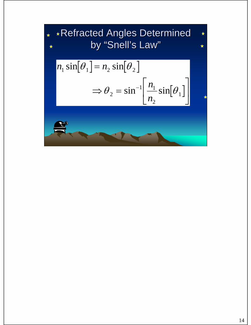
Refracted Angles Determined Refracted Angles Determined by by ““SnellSnell’’s Laws Law””
n n
nn
1 1 2 2
21 1
21
sin sin
sin sin
θ θ
θ θ
=
⇒ =LNM
OQP
−

15
Problem with Refracting Problem with Refracting Telescopes: Telescopes: ““Optical DispersionOptical Dispersion””• Refractive index n of glass is not constant• n of glass tends to DECREASE with increasing
wavelength λ• ⇒ Refracted angles change with wavelength λ• Focal length f of lens tends to INCREASE with
increasing wavelength λ– Different colors “focus” at different distances– “Chromatic Aberration”

16
Optical DispersionOptical Dispersion
n
λUltraviolet Infrared

17
Chromatic AberrationChromatic Aberration

18
Minimize Chromatic AberrationMinimize Chromatic Aberration
• Chromatic aberration is less noticeable for lenses with long focal lengths f

19
HeveliusHevelius’’ Refractor, ca. 1650Refractor, ca. 1650
H.C. King, History of the Telescope
Objective Lens
Eye Lens
20
Later Methods to Diminish Later Methods to Diminish Chromatic AberrationChromatic Aberration
• Create lens systems from multiple lenses made from different glasses– “doublets” or “triplets”– Designed so that chromatic aberrations “cancel” for
some wavelengths• Difficult to design and fabricate• Beyond capability of early optical technicians

21
““AchromaticAchromatic”” LensesLenses• “Achromatic” means
“no color”• Two (or more) lenses
with different glasses– “Crown”, with smaller n– “Flint”, with larger n

22
Easy Way to Eliminate Easy Way to Eliminate Chromatic AberrationChromatic Aberration
• Don’t use lenses!!
f
All colors “focus” at same distance f

23
NewtonNewton’’s Reflectors Reflector
• ca. 1671• 1"-diameter mirror• no chromatic
aberration – mirrors reflect all
wavelengths at the same angle!
H.C. King, History of the Telescope

24
Large Historical Reflecting Large Historical Reflecting TelescopeTelescope
H.C. King, History of the Telescope
Lord Rosse’s 1.8 m (6'-diameter) telescopemetal mirror, 1845

25
History of Imaging SensorsHistory of Imaging Sensors• Eye
– Limited sensitivity– Limited range of wavelengths– Images can be “stored” only “by hand” (drawings)
• Image Recording Systems– Chemical-based Photography
• wet plates, 1850 +• dry plates, 1880+• Kodak plates, 1900+
– Physics-based Photography, 1970 +• Electronic Sensors, CCDs

26
History of Imaging SensorsHistory of Imaging Sensors• Groundbased Infrared Imaging
– 1856: using thermocouples and telescopes (“one-pixel sensors”)
– 1900+: IR measurements of planets– 1960s: IR survey of sky (Mt. Wilson, lead
sulfide − PbS − detector)• Spacebased Infrared Imaging
– 1983: IRAS (Infrared Astronomical Satellite) • cooled Silicon and Germanium detectors
– 1989: COBE (Cosmic Background Explorer)

27
History of Imaging SensorsHistory of Imaging Sensors
• Airborne Infrared Observatories– Galileo I (Convair 990), 1965 – 4/12/1973
(crashed)– Frank Low, 12"–diameter telescope on NASA
Learjet, 1968– Kuiper Airborne Observatory (KAO) (36"-
diameter telescope)

28
Galileo I (Galileo I (ConvairConvair 990)990)
• Started in 1965 • Several “ports” available for cameras• Crashed 4/12/1973
– midair collision on landing at NAS Moffet

29
NASA Learjet, 1968NASA Learjet, 1968
• 12"–diameter telescope, by Frank Low

30
KuiperKuiper Airborne ObservatoryAirborne Observatory
• Modified C-141 Starlifter
• 2/1974 – 10/1995• ceiling of 41,000' is
above 99% of water vapor, which absorbs most infrared radiation

31
Stratospheric Observatory for Stratospheric Observatory for Infrared Astronomy Infrared Astronomy −− SOFIASOFIA
• Boeing 747SP• 2.7-m Mirror (106")

32
SpaceborneSpaceborne ObservatoriesObservatories
• “Orbiting Astronomical Observatory”(OAO), 1960s
• “Infrared Astronomical Satellite” (IRAS), 1980s
• Hubble Space Telescope (HST), 1990• Chandra (Advanced X-ray Astrophysics
Facility= AXAF), 7/1999

33
History of Imaging Systems for History of Imaging Systems for Radio AstronomyRadio Astronomy
• Wavelengths λ are much longer than visible light– millimeters (and longer) vs. hundreds of nanometers
• History– 1932: Karl Jansky (Bell Telephone Labs) investigated
use of “short waves” for transatlantic telephone communication
– 1950s: Plans for 600-foot “Dish” in Sugar Grove, WV (for receiving Russian telemetry reflected from Moon)
– 1960s 305m Dish at Arecibo, Puerto Rico– 1963: Penzias and Wilson (Bell Telephone Labs),
“Cosmic Microwave Background”– 1980: “Very Large Array” (= VLA) in New Mexico

34
JanskyJansky Radio TelescopeRadio Telescope
Image courtesy of NRAO/AUI
1932
35
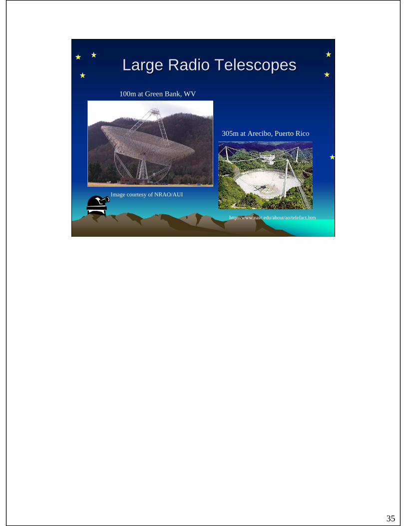
Large Radio TelescopesLarge Radio Telescopes
http://www.naic.edu/about/ao/telefact.htm
305m at Arecibo, Puerto Rico
100m at Green Bank, WV
Image courtesy of NRAO/AUI

36
Very Large Array = VLAVery Large Array = VLA
Image courtesy of NRAO/AUI
• 27 telescopes• 25m diameter• transportable on rails• separations up to 36 km (22 miles)