058chambers
DESCRIPTION
http://www.uponor.fi/~/media/countryspecific/finland/download-centre/technical-handbook-eng/058chambers.pdf?version=1TRANSCRIPT

uPONOr STOrMWATEr CHAMBEr SySTEMS 125
Sto
rm-
and
Was
tew
ater
Sy
stem
s
Advanced chamber system for ultra-effective environmental protection
UPONOR INFRASTRUCTURE
uPONOr STOrMWATEr CHAMBEr SySTEMS

126 uPONOr STOrMWATEr CHAMBEr SySTEMS
Sto
rm-
and
Was
tew
ater
Sy
stem
s
Pipe chambers perform a number of
vital functions in municipal wastewater,
stormwater and land drainage networks.
Straight pipeline stretches are normally
equipped with inspection chambers
or maintenance shafts, spaced every
40 metres or so. Modern pipeline clean-
ing, clearing and camera inspection
technologies have replaced the need
for personnel access to pipes. The cost
efficiency of pipe chambers has greatly
improved as a result. Chambers are also
typically built at changes in direction
and junctions.
5.8 Uponor chambers
Uponor chamber types
Chamber types are chosen according to
the pipeline's purpose of use. Commonly
used abbreviations for the different cham-
ber types are given in the table below.
In addition to chambers used in municipal
pipe systems, uponor’s chamber range
includes different chamber solutions for
building stormwater and land drainage
systems, and for farm and crop irriga-
tion requirements. uponor chambers are
classed into three main groups, based on
the type of delivery.
Table 5.8.1. Chamber types
Abbreviation Explanation
WWIC Wastewater inspection chamber, DN ≥ 400 mm
SWIC Stormwater inspection chamber without silt trap, DN ≥ 400 mm
SWC Stormwater chamber with silt trap and water trap, DN ≥ 400 mm
SGWC Storm- and groundwater attenuation chamber: a DN ≥ 560 subclass of the stormwater chamber. The chamber is equipped with a backflow prevention valve.
LDC Land drain chamber with silt trap DN ≥ 315 mm
IP Inspection pipe, i.e. smaller version of the wastewater inspection chamber, DN ≥ 200 mm
GH Rainwater gully hopper for roof water collection
WWIC SWIC SWC, SGWC LDC IP GH
Figure 5.8.2. Chamber types
uPONOr STOrMWATEr CHAMBEr SySTEMS 127
Sto
rm-
and
Was
tew
ater
Sy
stem
s
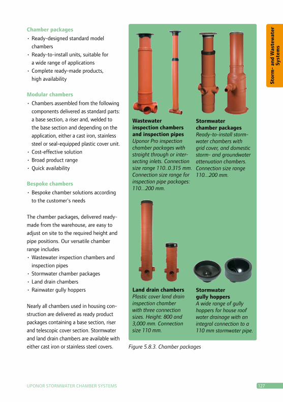
Chamber packages
•ready-designed standard model
chambers
•ready-to-install units, suitable for
a wide range of applications
•Complete ready-made products,
high availability
Modular chambers
•Chambers assembled from the following
components delivered as standard parts:
a base section, a riser and, welded to
the base section and depending on the
application, either a cast iron, stainless
steel or seal-equipped plastic cover unit.
•Cost-effective solution
•Broad product range
•Quick availability
Bespoke chambers
•Bespoke chamber solutions according
to the customer's needs
The chamber packages, delivered ready-
made from the warehouse, are easy to
adjust on site to the required height and
pipe positions. Our versatile chamber
range includes
•Wastewater inspection chambers and
inspection pipes
•Stormwater chamber packages
•Land drain chambers
•rainwater gully hoppers
Nearly all chambers used in housing con-
struction are delivered as ready product
packages containing a base section, riser
and telescopic cover section. Stormwater
and land drain chambers are available with
either cast iron or stainless steel covers.
Wastewater inspection chambers and inspection pipesUponor Pro inspection chamber packages with straight through or inter-secting inlets. Connection size range 110..0.315 mm. Connection size range for inspection pipe packages: 110...200 mm.
Stormwater chamber packagesReady-to-install storm-water chambers with grid cover, and domestic storm- and groundwater attenuation chambers. Connection size range 110...200 mm.
Land drain chambers Plastic cover land drain inspection chamber with three connection sizes. Height: 800 and 3,000 mm. Connection size 110 mm.
Stormwater gully hoppers A wide range of gully hoppers for house roof water drainage with an integral connection to a 110 mm stormwater pipe.
Figure 5.8.3. Chamber packages

128 uPONOr STOrMWATEr CHAMBEr SySTEMS
Sto
rm-
and
Was
tew
ater
Sy
stem
s
Modular chambers typically consist of
three standard components: a base sec-
tion, riser and cover section. Each base
section includes pipe connections; the
customer can select branch fittings for
these from uponor's range. Base sec-
tions are made from injection moulded
polypropylene.
due to the base section structure, post-
connections can be performed extremely
low down, if needed. The base section
and riser are factory weld-jointed, to
ensure a fully watertight and robust joint.
All modular stormwater chambers are
standard equipped with a skim board or
water trap.
Telescopic
cover section
Riser
Base section
Figure 5.8.4. All modular stormwater
chambers are standard equipped with a
skim board or water trap. Flushing pipe
connection, as shown in the figure above,
is also available as optional equipment.
Wastewater inspection chambers (WWIC) and inspection pipesInspection chamber with intersecting Uponor Pro base or straight channel base. Riser height: 400 and 560 mm. Connection size range: 110...315 mm.
Stormwater inspection chambers (SWIC)Inspection chamber with intersecting Uponor Pro base. Riser height: 400 and 560. Connections: 110–315 mm.
Land drain chambers (LDC) Equipped with a 315 or 400 mm riser and cast iron or stainless steel telescopic cover.
Stormwater chambers (SWC) Extensive selection of cham-bers for a range of applica-tions. Silt trap size range from 70 to 300 litres, depending on the chamber model. Equipped with telescopic riser and 40 t cast iron grate cover.
Figure 5.8.5. Modular chamber structure
Figure 5.8.6. Modular chambers

uPONOr STOrMWATEr CHAMBEr SySTEMS 129
Sto
rm-
and
Was
tew
ater
Sy
stem
s
Bespoke chambers are made to order
according to customer specifications. The
type, size, height, branch sizes and location
etc. of each chamber are determined in
line with the customer's drainage plan. A
chamber order form or offer request form
provide the best way of notifying uponor
of the required delivery specifications.
Bespoke chambers are produced to order
from welded PE preforms and delivered on-
site numbered and ready-to-install, each to
its own specific pipeline location. Bespoke
chambers can also be manufactured with a
largediameter(upto1800mm)orinline
with special height specifications. Figure 5.8.7
There are national regulations and guide-
lines concerning water supply and drainage
installations for buildings. Both the cham-
ber designer and manufacturer operate in
complete compliance with these standards,
regulations and guidelines. Some of the
design and production requirements are
listed below.
•Wastewater systems and their joints
must be leak-proof, i.e. chambers and
chamber joints must be watertight. For
wastewater chambers, watertightness is
also generally required of the chamber
sections above the flow line, to ensure
that leakage water is unable to enter the
wastewater system.
•Wastewater chambers must be equipped
with base channels for flow direction
• Inspection pipes may be one diameter
size smaller than the sewer, however at
least dN >= 160 mm
Approvals•Wastewater inspection chambers must
be at least dN 400 mm
• If the outlet pipe from a storm- and
groundwater attenuation chamber
is lower than the backwater level of
the public sewer, the outlet pipe
must be equipped with a self-acting
non-return valve.
•Stormwater inspection chambers with
aflat(non-channelled)basearealso
generally approved
•A stormwater chamber silt trap must
have a minimum volume of 70 litres
and a minimum height of 500 mm
•The silt trap height for land drain
chambers is min. 200 mm
•No external requirements exist for
stormwater gully hoppers.
For the latest updated standards, visit us
online at www.uponor.fi.
130 uPONOr STOrMWATEr CHAMBEr SySTEMS
Sto
rm-
and
Was
tew
ater
Sy
stem
s
In domestic housing applications, pipe
chambers are used in three separate
systems: wastewater, stormwater and land
drainage. Pipe systems must be made
accessible for maintenance and inspection
purposes, while pipe chambers used for
such a purpose must be totally watertight.
In house drains, either a wastewater
inspection chamber or inspection pipe
is used. Inspection chambers should be
installed at any horizontal or vertical
changes in direction, wherever junctions
between two or more drains occur, and at
intervals of 40 metres on straight pipes.
The following structural specifications ap-
ply to inspection chambers:
• Inside the chamber, the direction of
flow must not change by more than
45°. Sharper direction changes must be
carried out by installing a bend prior to
the chamber.
• Inspection chambers must have clearly
defined flow channels.
In inspection pipes, the flow is always
straight. If a direction change is neces-
sary, any bend must be installed prior to
the inspection pipe. A diagram of the ap-
propriate chamber type must be included
on pipe layout drawings. Joint heights
and the cover height and type must also
be clearly indicated on the drawings.
Surface waters are collected and chan-
nelled into the storm drain via grid-cover
stormwater chambers. Stormwater from
Chambers in the Drainage Plans
roofs is collected and channelled into the
storm drain via gullies. These roof and
surface waters converge in a stormwater
inspection chamber, from which they are
directed onwards to the main storm drain.
Pipe direction changes up to 90° can be
made in a stormwater inspection cham-
ber. Flow channels are not required and
the sections above the base do not need
to be watertight. The following chambers
are required for storm drainage:
•Gully hoppers for roof water collection
e.g. the uponor Plus stormwater gully
hopper.
•Stormwater chamber for surface
water collection SWC400/70 or
SWC 560/150
•Stormwater inspection chamber
Pro T2 400
•Storm- and groundwater attenuation
chamber 560/150 with non-return
ball valve.
When needed, land drainage inspec-
tion chambers serve as maintenance
points for flushing the drainage system.
The chamber provides maintenance
access for both input and outlet pipes.
designed for building land drainage
systems, the uponor 315 Land drain
Chamber comes equipped with a solid
cover, silt trap and easy-to-open con-
nections. The chamber height range
is one to three metres. If needed, the
chamber can also be manually shortened
by sawing to the desired height. Because
storm run-off must be kept separate

uPONOr STOrMWATEr CHAMBEr SySTEMS 131
Sto
rm-
and
Was
tew
ater
Sy
stem
s
Municipal pipe chambers are normally
equipped with a telescopic cast iron cover
section. Exceptions may include, for ex-
ample, sites where the chamber is installed
below groundwater level. In such cases,
the riser is fitted with a watertight cover.
Suitable inspection chambers for waste-
water lines include, for example, uponor
Pro chambers or the standard WWIC
model. These models are equipped with
a telescopic cast iron cover and integral
branch inlets for different pipe diameters.
In addition to stormwater inspection
chambers, standard stormwater chambers
are installed for surface water collection.
Such chambers are equipped with a tel-
escopic grid cover, water trap and optional
flushing pipe.
A schematic diagram of the chamber
must be included in the drainage plan.
Additionally, the chamber's branch con-
nection heights and the ground level
must be shown on the plan drawings. We
highly recommend using the enclosed
uponor Chamber Order Form as a simple
and effective way of ensuring that all of
the required information is provided.
from the land drain, the land drain
chamber cover must not be perforated
to serve as a grid cover.
For larger land drainage sites, a bigger
size class chamber, such as the LdC
400/35, is needed. These larger land
drain chambers are normally equipped
with a telescopic cover.
Municipal pipe chambers
Municipal sewer networks place higher
demands than household systems on
pipe chambers. For example, different
pipe sizes and tightness requirements
apply. Wastewater chambers must be
100% leak-proof and meet high flow
performance requirements. Stormwater
chambers are less demanding in terms of
tightness, but high structural durability is
required for both chamber types.
Some municipalities still require direct
chamber-to-chamber visibility for optical
and laser measurement purposes. This
also means that bends must not be in-
stalled. Instead, the chamber connections
must be ready-installed in the required
direction. For such cases, bespoke cham-
bers provide the ideal solution.
Figure 5.8.8. Bespoke chamber
Figure 5.8.9. Chamber location

132 uPONOr STOrMWATEr CHAMBEr SySTEMS
Sto
rm-
and
Was
tew
ater
Sy
stem
s
Figure 5.8.10. Uponor Chamber Order Form
CHAMBER ORDER OFFER REQUEST 20
Customer
Order no./ref.
Delivery date
Delivery address
Contact person , tel.
Wholesaler
Wholesaler order no.
Freight free Freight charge Pick up
*) Chamber height ’h’ measured from flow line to ground level. Note: Seal watertightness guaranteed only for Uponor pipes**) Pipe type, e.g. 1 = Ultra Rib 2 2 = Dupplex 2 3 = Uponor PVC 4 = Stormwater DW 5 = Drainage DW 6 = Drainage
CHAMBER No.
OUTLET
**) Pipe type
Connection size
Flow line height (cm)
Angular defl. degs.
Gradient cm/m
Outlet 0 0QUANTITY Inlet 1
Inlet 2
Inlet 3
SIZE (OD) Inlet 4
Telescopic ring: Bolted WeldedSolid cover 40 t
Cover without handleTelesc. riser 0.8 m mGrate cover 40 t Freeze protection HEIGHT *)
Water lock + flush pipeGrit trap depth: Standard m
Further information:
0
90
180
270
Not telescopic
Uponor Suomi OyP.O. Box 21, FI–15561 Nastola, FinlandTel. 020 129 211Fax +358 (0)20 129 210
Uponor Suomi OyKylänportti 2, FI–02940 Espoo, FinlandTel. 020 129 211Fax +358 20 129 2771
Uponor OySeenintie 13, FI-40320 Jyväskylä, FinlandTel. 020 129 211Fax +358 20 129 2751

uPONOr STOrMWATEr CHAMBEr SySTEMS 133
Sto
rm-
and
Was
tew
ater
Sy
stem
s
uponor offers a versatile range of cham-
bers for waste- and stormwater drain-
age and land drainage applications. The
following section gives a brief overview
of the different uponor chamber types.
At the end of the section is a chamber
selection table, from which you can easily
find the right chamber for the right ap-
plication.
Wastewater inspection chambers
and inspection pipes
Wastewater inspection chambers are used
in non-pressure drainage and sewerage
networks, and can be connected to both
smooth and corrugated or rib-stiffened
pipes. The base section of the inspection
Uponor Chamber Range
Figure 5.8.11. Wastewater inspection
chamber (WWIC) and inspection pipe
chamber comprises an injection moulded
base, attached to a corrugated and
seal-equipped riser socket. In addition,
itisequippedwitheitherstraight(T1)or
intersecting(T2)inlets.Baseelements
equipped with intersecting branch inlets
have three inlets set at 45° to one
another. The branch inlets and outlet
pipe are fitted with universal sockets that
are compatible with both smooth and
rib-stiffened pipes, eliminating the need
for adaptors.
uponor inspection chamber packages are
also available with adjustable Pro-Flex-
Joint connections. Their Pro-FlexJoints
enable inlet and outlet adjustment by
7.5 degrees in any direction.
Standard chamber packages include a
riser, a telescopic riser section, and a
40 t cast iron cover. Within the modular
chambers, the base section and riser are
welded together.
drain inspection pipes are inspection and
maintenance shafts that are smaller in
diameter than inspection chambers. The
inspection pipe comprises an inspec-
tion line and a riser, which can be either
uniform or telescopic, depending on the
installation site. Inspection pipes come
with either stainless steel or plastic cov-
ers. Inspection pipes intended for traffic
areas are equipped with a cast iron cover.
134 uPONOr STOrMWATEr CHAMBEr SySTEMS
Sto
rm-
and
Was
tew
ater
Sy
stem
s
Stormwater chambers and
inspection chambers
used for collecting surface and land
drainage waters, uponor’s stormwater
chambers have an extremely broad scope
of application. They can be divided into
the following main categories: road and
yard area stormwater chambers, and
storm- and groundwater attenuation
chambers. Stormwater chambers are used
to drain runoff from roadways, yard areas
or car parks. Chambers equipped with
a silt trap are used to prevent grit and
other debris from entering and blocking
the sewer system. The task of storm- and
groundwater attenuation chambers used
in domestic applications, is to combine the
building’s land and storm drainage lines.
Stormwater inspection chambers serve as
access points for pipe inspection and main-
tenance. These chambers are equipped with
either a telescopic or fixed riser and are also
available with a non-channelled flat base
section. Water tightness is not a requirement
for all sections of stormwater inspection
chambers. Pipe joints must, however, be fully
watertight. Inspection chambers are typically
equipped with a solid cast-iron cover.
Land drain chambers
Land drain chambers are installed in
land drainage systems to which access is
required for inspection purposes. These
chambers are often also installed at pipe
junctions and wherever changes in pipe
gradient or pipe size occur. An adjust-
able land drain chamber is a specialised
chamber used for crop irrigation. Such
a chamber can be used to regulate soil
moisture content according to weather
conditions and water demand.
Stromwater gully hoppers
The function of the stormwater gully hopper
is to catch roof stormwater from the drain-
pipe and channel it into the storm drain. The
hopper is equipped with a sieve to prevent
leaves and other debris from entering the
drain. Its bowl-like shape is specially de-
signed to protect the foundation wall from
splashing. The gully hopper also serves as an
access point for drain maintenance.
Figure 5.8.12. Stormwater chamber and
stormwater inspection chamber (SWIC)
Figure 5.8.14. Stromwater gully hoppers
Figure 5.8.13. Land drain chamber
uPONOr STOrMWATEr CHAMBEr SySTEMS 135
Sto
rm-
and
Was
tew
ater
Sy
stem
s
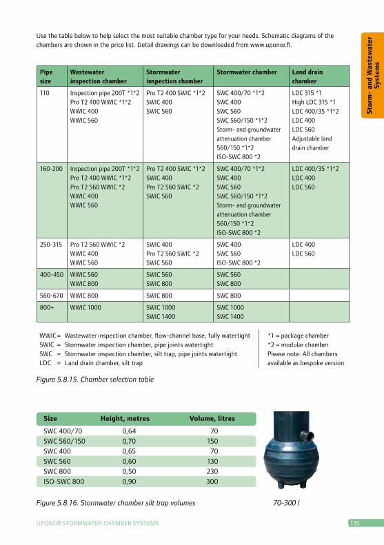
Pipe size
Wastewater inspection chamber
Stormwater inspection chamber
Stormwater chamber Land drain chamber
110 Inspection pipe 200T *1*2Pro T2 400 WWIC *1*2WWIC 400 WWIC 560
Pro T2 400 SWIC *1*2SWIC 400 SWIC 560
SWC 400/70 *1*2SWC 400 SWC 560 SWC 560/150 *1*2Storm- and groundwater attenuation chamber 560/150 *1*2ISO-SWC 800 *2
LDC 315 *1High LDC 315 *1LDC 400/35 *1*2LDC 400LDC 560Adjustable land drain chamber
160-200 Inspection pipe 200T *1*2Pro T2 400 WWIC *1*2Pro T2 560 WWIC *2WWIC 400WWIC 560
Pro T2 400 SWIC *1*2SWIC 400Pro T2 560 SWIC *2SWIC 560
SWC 400/70 *1*2SWC 400SWC 560SWC 560/150 *1*2Storm- and groundwater attenuation chamber 560/150 *1*2ISO-SWC 800 *2
LDC 400/35 *1*2LDC 400LDC 560
250-315 Pro T2 560 WWIC *2WWIC 400WWIC 560
SWIC 400Pro T2 560 SWIC *2SWIC 560
SWC 400SWC 560ISO-SWC 800 *2
LDC 400LDC 560
400-450 WWIC 560WWIC 800
SWIC 560SWIC 800
SWC 560SWC 800
560-670 WWIC 800 SWIC 800 SWC 800
800+ WWIC 1000 SWIC 1000SWIC 1400
SWC 1000SWC 1400
WWIC = Wastewater inspection chamber, flow-channel base, fully watertightSWIC = Stormwater inspection chamber, pipe joints watertightSWC = Stormwater inspection chamber, silt trap, pipe joints watertightLDC = Land drain chamber, silt trap
*1 = package chamber*2 = modular chamberPlease note: All chambers available as bespoke version
Use the table below to help select the most suitable chamber type for your needs. Schematic diagrams of the chambers are shown in the price list. Detail drawings can be downloaded from www.uponor.fi.
Figure 5.8.15. Chamber selection table
Size Height, metres Volume, litres
SWC 400/70 0,64 70 SWC 560/150 0,70 150 SWC 400 0,65 70 SWC 560 0,60 130 SWC 800 0,50 230 ISO-SWC 800 0,90 300
Figure 5.8.16. Stormwater chamber silt trap volumes 70-300 l

136 uPONOr STOrMWATEr CHAMBEr SySTEMS
Sto
rm-
and
Was
tew
ater
Sy
stem
s
Setting the chamber height
Thechamberheight(h)isthedistance
between the outlet flow line and ground
level. If the chamber has a silt trap, add
the trap depth to the total chamber height.
The height of the base section represents
the effective chamber height: i.e. the dis-
tance from the flow line to the base of the
vertical socket. If a telescopic cover sec-
tion is installed, its proportion of the total
height is normally 500 mm. The remaining
height is accounted for by the riser.
The riser height options for the modular
chambers are 600, 1,000, 1,500 or 2,000
mm, to which a standard-size telescopic
cover section is added for fine height
adjustment, giving the total riser height.
If necessary, the riser can be cut to length
on site. The cut end of the riser pipe must
be bevelled to match the original end of
the riser. Install the groundwater seal on
the bevelled end and brush lubricant over
the seal. Next, fit the telescopic ring into
place and screw it onto the riser.
The bespoke chamber's height is
measured from the flow line to ground
level. unless otherwise specified by the
customer, the telescopic cover section will
account for a default height of around
500 mm of the total chamber height.
Chamber embedment
The chamber must be laid in frost-
resistant embedment soil. The maximum
Chamber Installation
grain size is the same as for the equiva-
lent plastic pipe diameter. If, however,
the surround material is susceptible to
freezing, at least two layers of friction-
reducing plastic membrane must be
wound around the chamber, covering
the top of the base section, the riser and
the telescopic seal. This ensures that
possible freezing moves only the topmost
membrane layer, without raising the riser
or telescopic seal out of position.
Spade the embedment material around
the chamber and compact in approx.
20 cm layers. Check the straightness of
the chamber as backfilling proceeds.
In the case of stormwater chambers with
a grit trap, the pit dug to accommodate
the trap breaks the uniform trench foun-
dation. To prevent sinking, special care
must be taken to ensure proper compac-
tion of the backfill material beneath the
pipe–chamber joints.
Figure 5.8.17. The material surrounding
the grit trap must be compacted to the
same bearing capacity as the trench
bottom.

uPONOr STOrMWATEr CHAMBEr SySTEMS 137
Sto
rm-
and
Was
tew
ater
Sy
stem
s
Adjusting the chamber height
The height of the telescopic chamber +
main riser can be regarded as suitable
when the top of the main riser pipe is
30...50 cm below the final ground level.
do not leave the final telescopic cover
section resting on an over-length riser
or on the chamber frame. The riser can
be sawn shorter as necessary. Increased
height can be achieved by replacing the
riser with a longer one.
Raising the cover during repaving
during repaving, the chamber cover must
be raised level with the repaved surface.
To achieve this, the cover flange must
first be chiselled free of the existing pav-
ing. If the cover section cannot be moved
easily by lifting the flange, fasten a metal
Figure 5.8.18. Raising the cover during
repaving
or wooden beam to a cable and hoist,
and lower it through the turret section
of the telescopic riser. It will thereby act
as an anchor, when the cover section is
hoisted from beneath. If necessary, to
make raising easier, the ground around
the turret section must be dug away.
Anchoring the cover section
to the paving
during the construction and compaction
of the upper road pavement layers, the
telescopic cover sections of the chambers
are raised level with each construction
stage, so that they do not present an ob-
stacle to work machines. during asphalt
pavement, the cover section is raised by
a few centimetres and asphalt is tamped
beneath the cover flange. Finally, the
cover is forced down, for example, with
an excavator bucket, and rolled level with
the paved surface.
Inspection pipe installation
Inspection pipes are installed in the same
way as pipe chambers. The base section of
the prefabricated inspection pipe is set at
a fixed gradient, and the outlet is different
totheinlet(universalsocket).Forthis
reason, the flow direction is marked with
an arrow on the side of the base section.
1.5-5 tA15Green area
12.5 tB125 Pedestrian pavements and carparks
25 tC250Curb zone
40 tD400Road and heavy vehicle carparks
Figure 5.8.19. Strength grades for chamber covers according to the EN 124 standard

138 uPONOr STOrMWATEr CHAMBEr SySTEMS
Sto
rm-
and
Was
tew
ater
Sy
stem
s
1. Place the chamber in the trench, mak-
ing sure that the base is level. Check that
the inlets/outlet are in the right direction.
Connecting Uponor Ultra Rib 2 and Dupplex pipes
2. Remove the sealing ring from the
chamber socket.
3. Fit the pipe's own seal into the second
groove from the pipe end.
4. Brush the inside of the chamber socket
with lubricant.
5. Push the pipe home into the base of
the chamber socket.

uPONOr STOrMWATEr CHAMBEr SySTEMS 139
Sto
rm-
and
Was
tew
ater
Sy
stem
s
Connecting a smooth PVC pipe
1. Ensure that the pipe is the right length
for installation. Bevel the PVC pipe end.
2. Brush lubricant onto the pipe end.
3. Push the pipe home onto the base of
the chamber socket.

140