072-0300 opc-n2 manual issue 3 final 240415 -...
TRANSCRIPT

072-0300 Alphasense User Manual OPC-N2 Optical Particle Counter Issue 3
Alphasense Ltd Page 1 of 15 April 2015Sensor Technology House, 300 Avenue West, Skyline 120, Great Notley. Essex.CM77 7AA. UK
Tel: +44 (0) 1376 556700 - Fax: +44 (0) 1376 335899Email: [email protected] - Web: www.alphasense.com
The purpose of this manual is to explain how to set up, install and use the Alphasense OpticalParticle Counter OPC-N2 for measuring PM1, PM2.5 and PM10, as well as measuring particle sizedistributions in real time.
1 OPC-N2 Specification
All dimensions in millimetres (± 0.15 mm)
MEASUREMENT
Particle range (μm) Spherical equivalent size (based on RI of 1.5) 0.38 to 17Size categorisation (standard) Number of software bins 16Sampling interval (seconds) Histogram period 1.4 to 10Total Flow rate (typical)Sample flow rate (typical)
L/ minmL/ min
1.2220
Max particle count rate Particles/ second 10,000Coincidence probability % at 106 particles/ L 0.84
POWERMeasurement mode mA (typical) 175Non-measurement mode mA (typical) Laser at minimum power; fan off 95Transient power on start-up mW for 1 ms <5000Voltage range V DC 4.8 to 5.2
KEY SPECIFICATIONS
Digital Interface SPI (Mode 1), USB 2.0Data storage micro SD 16 GBUSB VID Ox04D8USB PID OxF3D5Laser classification as enclosed housing Class 1Temperature range °C -20 to 50Humidity range % rh (continuous) 0 to 95 (non-condensing)Weight g < 105
Table 1 Power and environmental performance limits
072-0300 Alphasense User Manual OPC-N2 Optical Particle Counter Issue 3
Alphasense Ltd Page 2 of 15 April 2015Sensor Technology House, 300 Avenue West, Skyline 120, Great Notley. Essex.CM77 7AA. UK
Tel: +44 (0) 1376 556700 - Fax: +44 (0) 1376 335899Email: [email protected] - Web: www.alphasense.com
2 How it WorksLike conventional optical particle counters, the OPC-N2 measures the light scattered by individualparticles carried in a sample air stream through a laser beam. These measurements are used todetermine the particle size (related to the intensity of light scattered via a calibration based on Miescattering theory) and particle number concentration. Particle mass loadings- PM1 PM2.5 or PM10,are then calculated from the particle size spectra and concentration data, assuming a particledensity and refractive index (RI). Default settings are: density 1.65 g/ml, RI 1.5+i0). Respiratoryprofiles are included in the PM calculations.
Most conventional OPCs employ a narrow inlet to physically constrain the airborne particles to passthrough a uniform central part of the illuminating laser beam and ensure accurate sizing. Suchinstruments incorporate both an air-pump sufficiently powerful to draw the sample aerosol throughthe narrow inlet tube and a particle filter upstream of the pump to avoid pump contamination andultimate blockage. The result is an OPC with high current consumption and a regular maintenancerequirement to replace the pump protection filter (frequent in dirty atmospheres).
The Alphasense OPC-N2 uses a different approach: we removed the pump and replaceable particlefilter. Instead, the patented OPC-N2 uses an elliptical mirror and dual-element photodetector tocreate a ‘virtual sensing zone’ in free space at the centre of an open scattering chamber.
The OPC-N2 classifies each particle size, at rates up to ~10,000 particle per second, recording theparticle size to one of 16 “bins” covering the size range from 0.38 to 17 μm. The resulting particlesize histograms can be evaluated over user-defined sampling times from 1 to 10 second duration.This histogram data and air temperature are transmitted via an SPI interface to a host computer.The patented OPC-N2 design results in virtually all sampled airborne particles passing straightthrough the sensor without being deposited, allowing the OPC-N2 to operate for very long periods(>1 year) without the requirement for regular maintenance or cleaning.
Consistent with most commercial Optical Particle Counters (OPCs), all particles, regardless ofshape are assumed to be spherical and are therefore assigned a ‘spherical equivalent size’. Thissize is related to the measurement of light scattered by the particle as defined by Mie theory, anexact theory to predict scattering by spheres of known size and refractive index (RI). The OPC-N2 iscalibrated using Polystyrene Spherical Latex Particles of a known diameter and known RI.Correction factors can be applied for errors resulting from particles of different density.
3 PM measurementsThe particle size histogram data recorded by the OPC-N2 sensor can be used to calculate the massof airborne particles per unit volume of air, normally expressed as μg/m3.
The accepted international standard definitions of particle mass loadings in the air are PM1, PM2.5and PM10. These definitions relate to the mass and size of particles that would be inhaled by atypical adult. So, for example, PM2.5 is defined as ‘particles which pass through a size-selective inletwith a 50% efficiency cut-off at 2.5 μm aerodynamic diameter’. The 50% cut-off indicates that aproportion of particles of larger than 2.5 μm will be included in PM2.5, the proportion decreasing withincreasing particle size, in this case out to approximately 10 μm particles.
072-0300 Alphasense User Manual OPC-N2 Optical Particle Counter Issue 3
Alphasense Ltd Page 3 of 15 April 2015Sensor Technology House, 300 Avenue West, Skyline 120, Great Notley. Essex.CM77 7AA. UK
Tel: +44 (0) 1376 556700 - Fax: +44 (0) 1376 335899Email: [email protected] - Web: www.alphasense.com
The OPC-N2 calculates the respective PM values according to the method defined by EuropeanStandard EN 481. Conversion from the ‘optical size’ of each particle as recorded by the OPC-N2and the mass of that particle requires knowledge of both particle density and its RI at thewavelength of the illuminating laser beam, 658 nm. The latter is required because both the intensityand angular distribution of scattered light from the particle are dependent on RI. The OPC-N2assumes an average RI value of 1.5 + i0. For particle density, the OPC-N2 allows a different valueto be set for each size bin. The default setting for each size bin is a Particle Density value of 1.65g/ml, a figure that equates to a typical value found in many environments. However, where it isknown that different size fractions in the ambient aerosol have different densities (for example, thesmallest clay particles may have a higher density than larger aggregates of the same particles)different Particle Density values may be set for different bins to achieve a more accuratedetermination of PM. Contact Alphasense for instructions to modify the particle bin density. TheOPC-N2 also has a Sample Volume Weighting factor for each size bin that is applied to the totalmass of particles in that bin. The default values are those defined by European Standard EN 481 forPM1, PM2.5 and PM10.
Notes• The OPC-N2 calculations of particle mass assume a negligible contribution from particles
below approximately 0.38 μm, the lower limit of particle detection of the OPC-N2 sensor.• The EN 481 standard definition for PM10 extends to particle sizes beyond the upper
measurable size limit of the OPC-N2. In some cases, this can result in the reported PM10value being underestimated by up to ~10%.
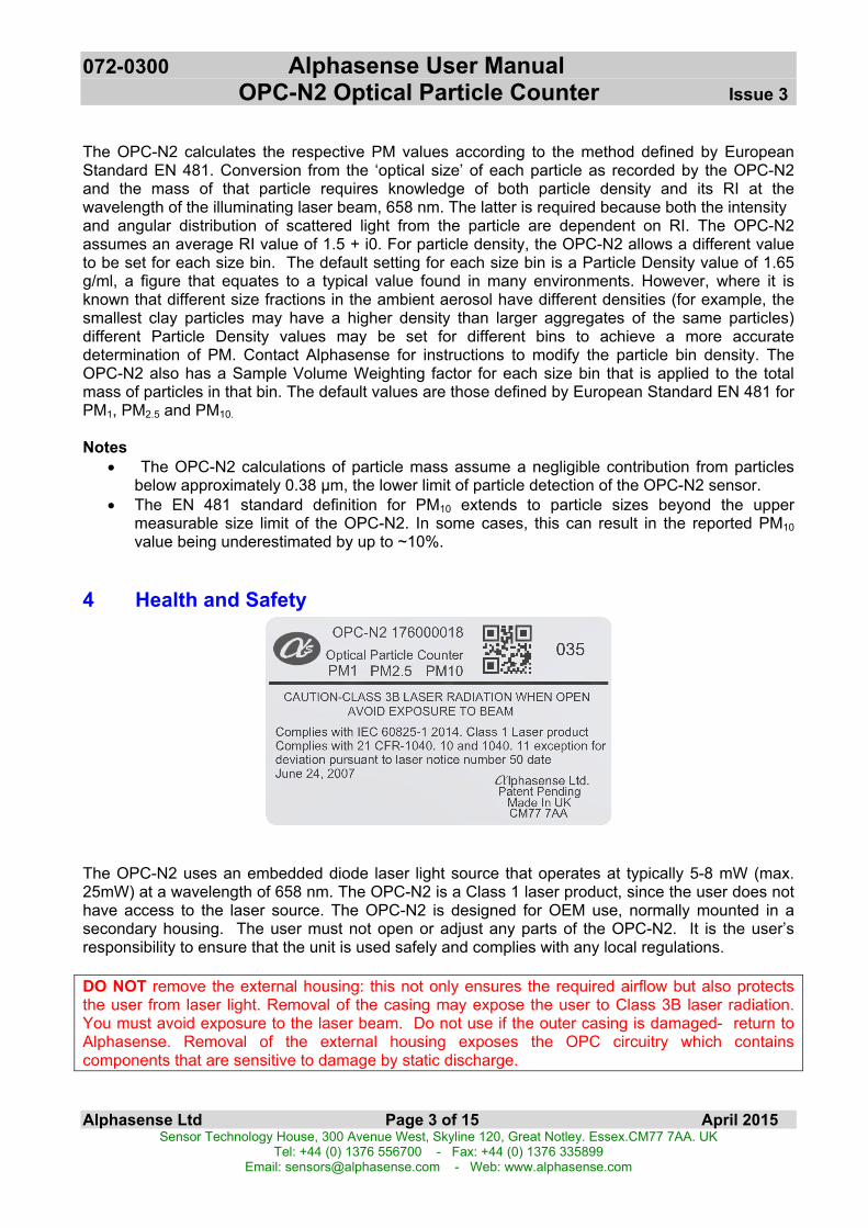
4 Health and Safety
The OPC-N2 uses an embedded diode laser light source that operates at typically 5-8 mW (max.25mW) at a wavelength of 658 nm. The OPC-N2 is a Class 1 laser product, since the user does nothave access to the laser source. The OPC-N2 is designed for OEM use, normally mounted in asecondary housing. The user must not open or adjust any parts of the OPC-N2. It is the user’sresponsibility to ensure that the unit is used safely and complies with any local regulations.
DO NOT remove the external housing: this not only ensures the required airflow but also protectsthe user from laser light. Removal of the casing may expose the user to Class 3B laser radiation.You must avoid exposure to the laser beam. Do not use if the outer casing is damaged- return toAlphasense. Removal of the external housing exposes the OPC circuitry which containscomponents that are sensitive to damage by static discharge.
072-0300 Alphasense User Manual OPC-N2 Optical Particle Counter Issue 3
Alphasense Ltd Page 4 of 15 April 2015Sensor Technology House, 300 Avenue West, Skyline 120, Great Notley. Essex.CM77 7AA. UK
Tel: +44 (0) 1376 556700 - Fax: +44 (0) 1376 335899Email: [email protected] - Web: www.alphasense.com
5 Connecting power and taking readingsThe OPC-N2 is shipped pre-calibrated. There are no user serviceable parts. Power and datacommunications are provided via the SPI socket. Firmware uploading and SD card downloading arevia the micro-USB socket. Use of the SD card will require internal firmware updating if the firmwareversion is prior to version 0015d.
Connection to the OPC-N2 for real-time data transfer can be made via the SPI direct to your owncircuit’s internal bus using your own-provided SPI interface. The micro-USB socket can be used forupdating the internal firmware and downloading the SD card measured data. See page 15 forfurther firmware information.When first using this OPC, we recommend that you use the SPI adapter. You can then view thedata options along with the data resolution and range when the OPC-N2 is connected to your PC,that has the Alphasense-supplied software installed. Apple compatible software is not yet available.Pin assignments for the SPI adapter are shown in Table 2 below. The green LED shows that poweris supplied to the OPC-N2 and the red LED flashes when the PC and OPC-N2 are communicating.
The OPC-N2 requires a 4.8 to 5.2 Volt DC supply with minimum noise. On-board regulators supplypower to the laser and fan. Required current is 175 mA when operating/ measuring and 95 mAwhen the fan is disabled and laser is operating at its lowest power setting. There is a very short oneamp current surge at switch-on.
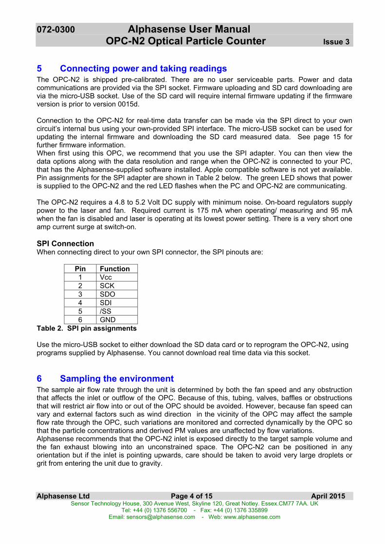
SPI ConnectionWhen connecting direct to your own SPI connector, the SPI pinouts are:
Pin Function1 Vcc2 SCK3 SDO4 SDI5 /SS6 GND
Table 2. SPI pin assignments
Use the micro-USB socket to either download the SD data card or to reprogram the OPC-N2, usingprograms supplied by Alphasense. You cannot download real time data via this socket.
6 Sampling the environmentThe sample air flow rate through the unit is determined by both the fan speed and any obstructionthat affects the inlet or outflow of the OPC. Because of this, tubing, valves, baffles or obstructionsthat will restrict air flow into or out of the OPC should be avoided. However, because fan speed canvary and external factors such as wind direction in the vicinity of the OPC may affect the sampleflow rate through the OPC, such variations are monitored and corrected dynamically by the OPC sothat the particle concentrations and derived PM values are unaffected by flow variations.Alphasense recommends that the OPC-N2 inlet is exposed directly to the target sample volume andthe fan exhaust blowing into an unconstrained space. The OPC-N2 can be positioned in anyorientation but if the inlet is pointing upwards, care should be taken to avoid very large droplets orgrit from entering the unit due to gravity.

072-0300 Alphasense User Manual OPC-N2 Optical Particle Counter Issue 3
Alphasense Ltd Page 5 of 15 April 2015Sensor Technology House, 300 Avenue West, Skyline 120, Great Notley. Essex.CM77 7AA. UK
Tel: +44 (0) 1376 556700 - Fax: +44 (0) 1376 335899Email: [email protected] - Web: www.alphasense.com
7 Software installationThe examples below are for installation using Microsoft Windows XP and Microsoft Windows 7.Please contact Alphasense directly if you are using Windows 8. It is recommended that theWindows PC is running .NET version 3.5 or above.
Installing the device driver (Windows XP)Copy the folder “OPC Interface Software” to the PC desktop. Connect the USB interface lead to thePC. If the USB interface lead (USB to SPI converter) is connected to the PC for the first time,Windows will need a device driver and this will start the “Found New Hardware” wizard.
Select the “Yes, this time only” option and click next.
The following window will give you an option as to whether to use a CD to install the device driver orto use another location. Select “Install from a list or a specific location (Advanced)”.Navigate to the OPC folder containing the folder named “USB Driver”, this contains the driver filedevtech2.inf which Windows needs to drive the OPC device.
Click OK to allow Windows to locate and install the device driver. This process is automatic but youwill be prompted by the form below to confirm the installation.
072-0300 Alphasense User Manual OPC-N2 Optical Particle Counter Issue 3
Alphasense Ltd Page 6 of 15 April 2015Sensor Technology House, 300 Avenue West, Skyline 120, Great Notley. Essex.CM77 7AA. UK
Tel: +44 (0) 1376 556700 - Fax: +44 (0) 1376 335899Email: [email protected] - Web: www.alphasense.com
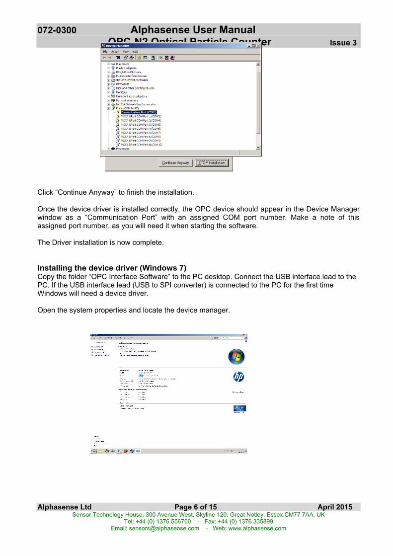
Click “Continue Anyway” to finish the installation.
Once the device driver is installed correctly, the OPC device should appear in the Device Managerwindow as a “Communication Port” with an assigned COM port number. Make a note of thisassigned port number, as you will need it when starting the software.
The Driver installation is now complete.
Installing the device driver (Windows 7)Copy the folder “OPC Interface Software” to the PC desktop. Connect the USB interface lead to thePC. If the USB interface lead (USB to SPI converter) is connected to the PC for the first timeWindows will need a device driver.
Open the system properties and locate the device manager.
072-0300 Alphasense User Manual OPC-N2 Optical Particle Counter Issue 3
Alphasense Ltd Page 7 of 15 April 2015Sensor Technology House, 300 Avenue West, Skyline 120, Great Notley. Essex.CM77 7AA. UK
Tel: +44 (0) 1376 556700 - Fax: +44 (0) 1376 335899Email: [email protected] - Web: www.alphasense.com
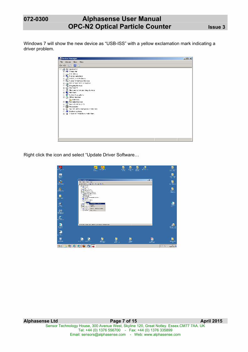
Windows 7 will show the new device as “USB-ISS” with a yellow exclamation mark indicating adriver problem.
Right click the icon and select “Update Driver Software…
072-0300 Alphasense User Manual OPC-N2 Optical Particle Counter Issue 3
Alphasense Ltd Page 8 of 15 April 2015Sensor Technology House, 300 Avenue West, Skyline 120, Great Notley. Essex.CM77 7AA. UK
Tel: +44 (0) 1376 556700 - Fax: +44 (0) 1376 335899Email: [email protected] - Web: www.alphasense.com
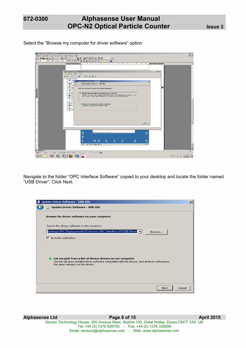
Select the “Browse my computer for driver software” option.
Navigate to the folder “OPC Interface Software” copied to your desktop and locate the folder named“USB Driver”, Click Next.

072-0300 Alphasense User Manual OPC-N2 Optical Particle Counter Issue 3
Alphasense Ltd Page 9 of 15 April 2015Sensor Technology House, 300 Avenue West, Skyline 120, Great Notley. Essex.CM77 7AA. UK
Tel: +44 (0) 1376 556700 - Fax: +44 (0) 1376 335899Email: [email protected] - Web: www.alphasense.com
Windows 7 will then issue a security warning. This is due to a licence issue and not a concern to theoperating system. Select the “Install this driver software anyway” option.
Windows will then install the driver files for the device.
Once the device driver software has been installed the form below will be displayed. Make a note ofthe allocated COM port number (COM4 in the example below)

072-0300 Alphasense User Manual OPC-N2 Optical Particle Counter Issue 3
Alphasense Ltd Page 10 of 15 April 2015Sensor Technology House, 300 Avenue West, Skyline 120, Great Notley. Essex.CM77 7AA. UK
Tel: +44 (0) 1376 556700 - Fax: +44 (0) 1376 335899Email: [email protected] - Web: www.alphasense.com
Incorrect installation of the device driverIf the device driver is installed incorrectly the Device Manager will indicate this with a yellowexclamation mark symbol shown below.
If this should happen remove the USB lead and uninstall the device by right clicking the symbol andselecting “Uninstall”. Return to the beginning of the “Installing the device driver” (Windows XP orWindows 7) section.
There is no uninstall function for the software interface. The interface is stored as a set of files in asingle folder (to be kept intact) and will run as a normal Windows application. The entire folder canbe deleted when redundant.
Connecting the device and running the softwareConnect the USB-SPI interface lead and OPC device to the PC. If you are prompted for devicedrivers refer to the previous section of the user manual. Double click the OPC-N2.exe icon to startthe software application. When the application is first started the main form will be in “start-up mode”as shown in section 8.
Run the software as with previous versions and connect to the OPC-N2 by choosing the virtualCOM port it is assigned to. Some text should appear in the software’s main text box indicating somedetails of the OPC on successful connection. At this stage the OPC is on, but the laser is running atreduced power. Press Ctrl+R to read out all the configuration variables stored the OPC. See page15 for more information on firmware variables.

072-0300 Alphasense User Manual OPC-N2 Optical Particle Counter Issue 3
Alphasense Ltd Page 11 of 15 April 2015Sensor Technology House, 300 Avenue West, Skyline 120, Great Notley. Essex.CM77 7AA. UK
Tel: +44 (0) 1376 556700 - Fax: +44 (0) 1376 335899Email: [email protected] - Web: www.alphasense.com
8 Data Display Screens
Default start-up screenSelect the allocated COM port: A list of COM ports available on the PC/Laptop is displayed in thedrop-down menu at the bottom-left of the screen. Be sure to select the correct port number; thesoftware will not respond unless the port with the attached OPC-N2 device is selected.
• If particle density of ambient particles is known to be different from the default setting (1.65g/ml), please contact Alphasense for details on how to change this value.
• Device information (Right hand side text window): This shows hardware serial number andfirmware versions currently installed on the OPC-N2.
• Start sampling: Starts data collection with the fan and laser running continuously. Thebutton will then show ‘Stop sampling’ to allow termination of the sampling process.
• Repeat interval ms: Sets the duration (in milliseconds) over which a particle size histogramis acquired. The default is 1,000 ms. We recommend a maximum of 10,000 ms to avoid therisk of an individual size bin becoming full (65,536 counts). Longer intervals can be set invery clean environments.
• Y max: This sets the maximum y-axis value of the histogram screen display. Note: If thedisplayed data reaches the top of the display, enter a larger Y max value.
• Histogram y-axis ‘Counts/ s’: This displays the recorded counts per second in each size bin,regardless of the setting of the ‘Repeat interval ms’. For example, if a 10,000 ms samplinginterval is set, the ‘Counts/ s’ figure will represent the average counts per second over thatperiod.
072-0300 Alphasense User Manual OPC-N2 Optical Particle Counter Issue 3
Alphasense Ltd Page 12 of 15 April 2015Sensor Technology House, 300 Avenue West, Skyline 120, Great Notley. Essex.CM77 7AA. UK
Tel: +44 (0) 1376 556700 - Fax: +44 (0) 1376 335899Email: [email protected] - Web: www.alphasense.com
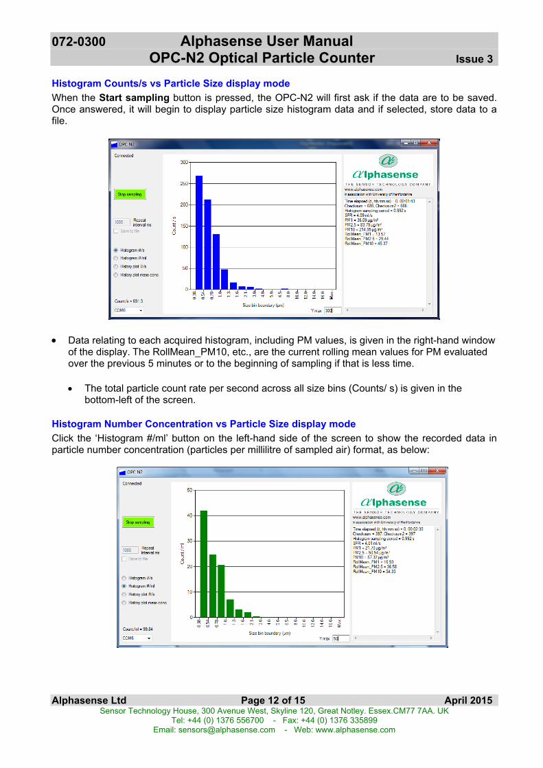
Histogram Counts/s vs Particle Size display modeWhen the Start sampling button is pressed, the OPC-N2 will first ask if the data are to be saved.Once answered, it will begin to display particle size histogram data and if selected, store data to afile.
• Data relating to each acquired histogram, including PM values, is given in the right-hand windowof the display. The RollMean_PM10, etc., are the current rolling mean values for PM evaluatedover the previous 5 minutes or to the beginning of sampling if that is less time.
• The total particle count rate per second across all size bins (Counts/ s) is given in thebottom-left of the screen.
Histogram Number Concentration vs Particle Size display modeClick the ‘Histogram #/ml’ button on the left-hand side of the screen to show the recorded data inparticle number concentration (particles per millilitre of sampled air) format, as below:
072-0300 Alphasense User Manual OPC-N2 Optical Particle Counter Issue 3
Alphasense Ltd Page 13 of 15 April 2015Sensor Technology House, 300 Avenue West, Skyline 120, Great Notley. Essex.CM77 7AA. UK
Tel: +44 (0) 1376 556700 - Fax: +44 (0) 1376 335899Email: [email protected] - Web: www.alphasense.com
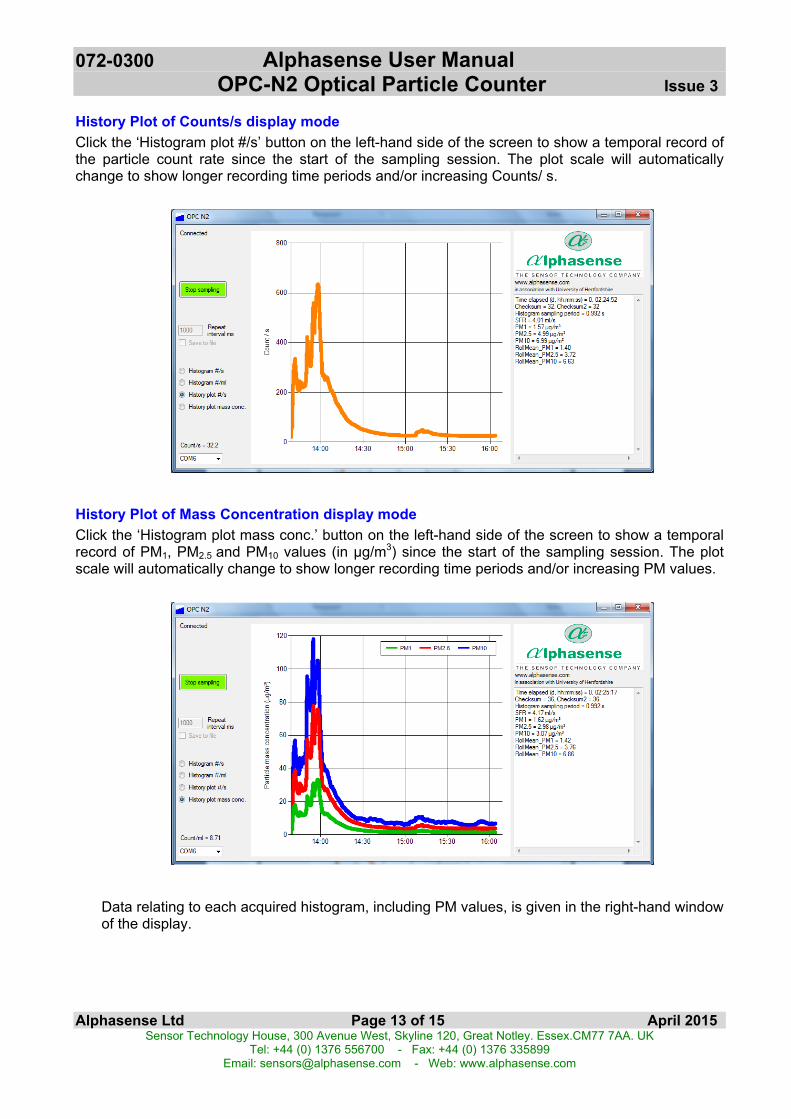
History Plot of Counts/s display modeClick the ‘Histogram plot #/s’ button on the left-hand side of the screen to show a temporal record ofthe particle count rate since the start of the sampling session. The plot scale will automaticallychange to show longer recording time periods and/or increasing Counts/ s.
History Plot of Mass Concentration display modeClick the ‘Histogram plot mass conc.’ button on the left-hand side of the screen to show a temporalrecord of PM1, PM2.5 and PM10 values (in µg/m3) since the start of the sampling session. The plotscale will automatically change to show longer recording time periods and/or increasing PM values.
Data relating to each acquired histogram, including PM values, is given in the right-hand windowof the display.

072-0300 Alphasense User Manual OPC-N2 Optical Particle Counter Issue 3
Alphasense Ltd Page 14 of 15 April 2015Sensor Technology House, 300 Avenue West, Skyline 120, Great Notley. Essex.CM77 7AA. UK
Tel: +44 (0) 1376 556700 - Fax: +44 (0) 1376 335899Email: [email protected] - Web: www.alphasense.com
9 Other Software Functions
Shutting down the softwareIt is recommended that the software application be closed before removing the USB to SPI interfaceto avoid USB communication errors.
Log fileThe application will also create a log file from all of the output bins into a single .CSV file. You will beasked if you require a log file after selecting the “start” button. If you select “yes” you will beprompted for a file name and location to store the file. An example of the log file is included in thedeployment package.
Firmware informationThe information window on the right of the main form shows the firmware version installed as thesoftware first loads up. The OPC-N2 also has the ability install firmware upgrades via the USB port.This is achieved using a Bootloader tool, contact Alphasense to obtain access to the Bootloader toolUser Manual. To check to see if your device can upgrade firmware via the USB port, check theinformation string printed as the device is first connected. To upgrade firmware via USB you need tohave firmware version 0015d or above.
Example: “OPC-N2 FirmwareVer=OPC-015d…………………………..BD”
As the firmware first loads it follows the procedure below:Check for SD memory card. All versions of the OPC-N2 will come with a 16GB micro SD card fitted.This card is internal and is not accessible from outside the case, please note it may not be fitted onearly release OPC-N2 or OPC-N1.1. If a SD card is found, the OPC will check for a USB connection. The OPC-N2 comes equipped
with a micro USB port.2. If a USB connection is found the device will switch to “USB mode”. This makes the OPC-N2
behave like an external storage device (pen-drive) until the USB is disconnected.3. If a USB connection is not found then it will check for the SPI master connection (SCLK). The
OPC will wait up to 60 seconds for an SPI connection to be established.4. If an SPI connection is not found the OPC-N2 will switch to “SD card mode”, This will create a
new file on the SD card (.csv format) and continue to log data. A new data file will be createdevery 24 hrs. When in SD card mode the SPI is still active, if SPI command “SPIShutDownDAC”(0x03) is sent, the OPC will close the current SD card log file and exit SD card mode.
More firmware commands (via software)There are four commands that can be used edit factory settings through the OPC software:1. Ctrl + R: Read and display all configuration variables. This will display the variables available to
the user for edit. The data is displayed in the information window to the right of the softwarewindow.
2. Ctrl + W: Write all values to configuration memory. This command will write the currentconfiguration values to volatile memory, this means that the user can run the OPC with theirdesired configuration but the changes will be reset once the power is disconnected.
3. Ctrl + S: Save all values to configuration memory. This command will write the currentconfiguration values to non-volatile memory, this means that the user can permanently savetheir configuration values.
4. Ctrl + B: Enter Bootloader mode. This allows the OPC to interact with the Bootloader applicationso that new firmware can be installed via USB port.

072-0300 Alphasense User Manual OPC-N2 Optical Particle Counter Issue 3
Alphasense Ltd Page 15 of 15 April 2015Sensor Technology House, 300 Avenue West, Skyline 120, Great Notley. Essex.CM77 7AA. UK
Tel: +44 (0) 1376 556700 - Fax: +44 (0) 1376 335899Email: [email protected] - Web: www.alphasense.com
10 OPC-N2 Factory settings
The OPC firmware retains the factory settings and calibrations.These settings should not be modified as this will affect the OPC calibration and its accuracy.If you wish to modify any of these settings, then contact Alphasense at (+44) 1376 556700.
The following parameters are factory set and stored in the firmware:
Bin boundaries The upper and lower particle size limits defining each ofthe 16 size bins.
Bin particle volumes (um3) The volume ascribed to each particle in that bin infirmware.
Bin particle volumes by software (um3) The volume ascribed to each particle in that bin insoftware (parameter present to confirm firmware values,which should be the same).
Bin particle densities (g/ml) The density ascribed to each particle in that bin. Thedefault setting is 1.65 g/ml for all bins.
Bin sample volume weightings Correction for size dependent sampling efficiency.Normally set to 1.0.
Gain scaling coefficient A global factor to normalise between units. Normally1.0.
Laser digital pot setting A parameter to determine laser beam power.
Fan digital pot setting A parameter to determine fan speed.
NOTE: Changing either the fan speed or laser power will change calibration and the OPC-N2 willrequire recalibration. When the OPC-N2 is not sampling, both the laser and fan are switchedautomatically to low-power settings.
End of User Manual