1--------------------------------1 performing organization
TRANSCRIPT

1. Report No.
VTRC 91-R7
2. Government Acce••lon No.
Technical Report Documentation Page
3. Recipient'. Catalog No.
4. nUe and SUbtitle
Installation and Performance Evaluation of theWabocrete FMV Joint System for Bridge Decks
5. Report Date
August 19906. Performing Organization Code
1--------------------------------1 8. Performing Organization Report No.7. Authorts)
Marvin H. Hilton9. Performing Organization Name and Addre••
Virginia Transportation Research CouncilBox 3817 University StationCharlottesville, Va. 22903
12. Sponsortng Agency N_ame and Addre.s
Federal Highway AdministrationP.O. Box 10045Richmond, Va. 23240-0045
15. Supplementary Not.s
None
10. Work Unit No. (TRAIS)
11. Contract or Grant No.
13. Type of Report and Period Covered
Final Report (11/86, 1/90)
14. Sponsoring Agency Code
16. Ab.tract A Vabocrete FMV bridge deck expansion joint system was installed on theAlternate Rte. 58 bridge over the Clinch River in November 1986. The bridge wasplaced in service in mid-1987. The report concerns an installation andperformance evaluation of the joint system.
It was found that the Wabocrete FMV joint system offers some installationadvantages over prefonmed joint systems. The blockout area of the bridge deckdoes not have to be as smooth or as precisely dimensioned since the joint'sanchorage system can be leveled prior to placement of the bonding material.Installation and future maintenance problems involving anchor bolts areeliminated since the system relies on bond rather than mechanical anchorages.
After over two years of service, the Vabocrete system has performed well.During this period, the joint has accomodated all thermal and structuralmovements, withstood traffic impacts and remained leakproof. The joint doestend to accumulate debris and should be routinely cleaned.
The performance of the joint during the period of the study has not givenany reason to suggest that it not be used on new bridge decks similar to the onestudied. A longer term evaluation, however, would be necessary for a fullrecommendation.
The use of the Yabocrete FMV, and similar systems, as retrofit on olderbridges should be approached with caution. Furthermore, these systems shouldprobably not be used in retrofit situations in conjunction with adjacentasphaltic overlays.
17. Key Word.Installation, performance bond, joints,bridge deck, blockout, extrusion, seal,anchorage, binder, elastomeric
18. Distribution Statement
19. Security CI.slf. (of this report)
Unclassified
Form DOT F 1700.7 (8-72)
20. Security Clas.lf. (of this page.
Unclassified
Reproduction of completed page authorized
21. No. of Page. 22. Price

I
I
I
I
I
I
I
I
I
I
I
I
I
I
I
I
I
I
I
I
I
I
I
I
I
I
I
I
I
I
I
I
I
I
I
I
I
I
I
I
I
I
I
I
I
I
I
I
I
I
I
I
I
I
I
I
I
I
I
I
I
I
I
I
II

FINAL REPORT
INSTALLATION AND PERFORMANCE EVALUATIONOF THE WABOCRETE FMV JOINT SYSTElVI FOR BRIDGE DECKS
Marvin H. HiltonSenior Research Scientist
(The opinions, findings, and conclusions expressed in thisreport are those of the author and not necessarily
those of the sponsoring agencies.)
Virginia Transportation Research Council(A Cooperative Organization Sponsored Jointly by the
Virginia Department of Transportation andthe University of Virginia)
In Cooperation with the U. S. Department of TransportationFederal Highway Administration
Charlottesville, Virginia
August 1990VTRC 91-R7
98S

BRIDGE RESEARCH ADVISORY COMMITTEE
C. A. NASH, Chairman, District Administrator, Virginia Department of Transportation
W. T. MCKEEL, Executive Secretary, Senior, Research Scientist, Virginia Transportation Research Council
J. E. ANDREWS, Assistant State Structure and Bridge Engineer, Virginia Department of Transportation
G. W. BOYKIN, District Materials Engineer, Virginia Department of Transportation
T. W. EATON, Management Services Division
A. B. JOHNSON, Assistant Construction Engineer
L. L. MISENHEIMER, District Bridge Engineer, VIrginia Department of Transportation
R. H. MORECOCK, District Bridge Engineer, VIrginia Department of Transportation
C. NAPIER, Structural Engineer, Federal Highway Administration
W. L. SELLARS, District Bridge Engineer, Virginia Department of Transportation
F. G. SUTHERLAND, State Structures & Bridge Engineer, Vtrginia Department ofTransportation
L. R. L. WANG, Professor & Chairman, Department of Civil Engineering, Old Dominion University

FINAL REPORT
INSTALLATION AND PERFORMANCE EVALUATIONOF THE WABOCRETE FMV JOINT SYSTEM FOR BRIDGE DECKS
Marvin H. Hilton
INTRODUCTION
One of the most persistent problems associated with the design, construction,and maintenance of bridge superstructures is the bridge deck joint. Virtually all of thebridges that are in service in the state of Virginia have two or more joints. In fact,this is true of most of the bridges in almost every state in the nation. Because of thelarge number of bridge joints, widespread performance and maintenance problems canvery rapidly become a costly problem. In addition to costs associated with repairing orreplacing the joint itself, leakage at a joint can lead to serious steel corrosion as wellas concrete deterioration in substructure elements.
The large number of bridge joints in the inventory is also an enticing market forindustry. Over the last 25 years or more, there have been a wide variety of proprietary bridge joints introduced into the market. The performance of the proprietaryjoints has varied. Some of the factors affecting the performance include the basic design of the joint system, the anchorage system, the methods (and care) used during installation, and the susceptibility of the joint to traffic. One of the more recent types ofbridge deck joints that has been introduced to the market is called the Wabocrete FMVElastomeric Concrete System (1). This system was installed as an experimental feature on a bridge located in the western part of the state of Virginia in November of1986. This report is an evaluation of the installation and a performance evaluation ofthe joint system after being subjected to normal traffic over a period of slightly morethan two years.
THE WABOCRETE FMV JOINT
A recent National Cooperative Highway Research Program Synthesis, entitledBridge Deck Joints (2), classifies the various joints by type. Although the WabocreteFMV joint is somewhat different from all the types described, it can generally be classified as an elastomeric strip seal. It differs from most strip seals in the manner thatit is anchored to the bridge deck. Whereas the earlier strip seals were attached tosteel or aluminum angles, which, in turn, were mechanically anchored to the deck, theWabocrete FMV strip seal is mounted to steel extrusions, which, in turn, are anchoredin an elastomeric concrete that is bonded to the deck. The bond between the elasto-
98 i

meric concrete and the bridge deck holds the joint system in place. A view of thejoint system is shown in Figure 1. It should be noted that the steel extrusions are anchored in the Wabocrete FMV (field vulcanized) elastomeric concrete by a sinusoidallyshaped steel bar. The strip seal stretches across the joint opening and serves to protect the lower structural elements of the bridge.
NEOPRENESTRIP SEAL -..,..--...,..-../1
STEELEXTRUSIONS -.......- ....~.....fi!*J
SINUSOIDAL~--~+- ANCHORAGE
Figure 1. Details of the Wabocrete FMV elastomeric concrete expansion joint system.
An important advantage of the Wabocrete FMV and other bridge deck joints ofsimilar design is that problems associated with the setting of anchor bolts in the concrete deck are eliminated. In addition, the need for a smooth and even blockout area,such as would be required for a plank seal design, is eliminated.
The elastomeric concrete in the Wabocrete FMV joint system is composed ofsynthetic rubber and aggregates that are, respectively, vulcanized and bonded togetherin the field. The material is purported to be resistant to traffic wear, sunlight, ozone,chlorides, and abrasives and resists brittleness at low temperatures and softening athigh temperatures. With the continuous strip seal gland and with the fusion bondedelastomeric concrete placed in a continuous fashion, the joint system is considered tobe leak proof.
2
98~j
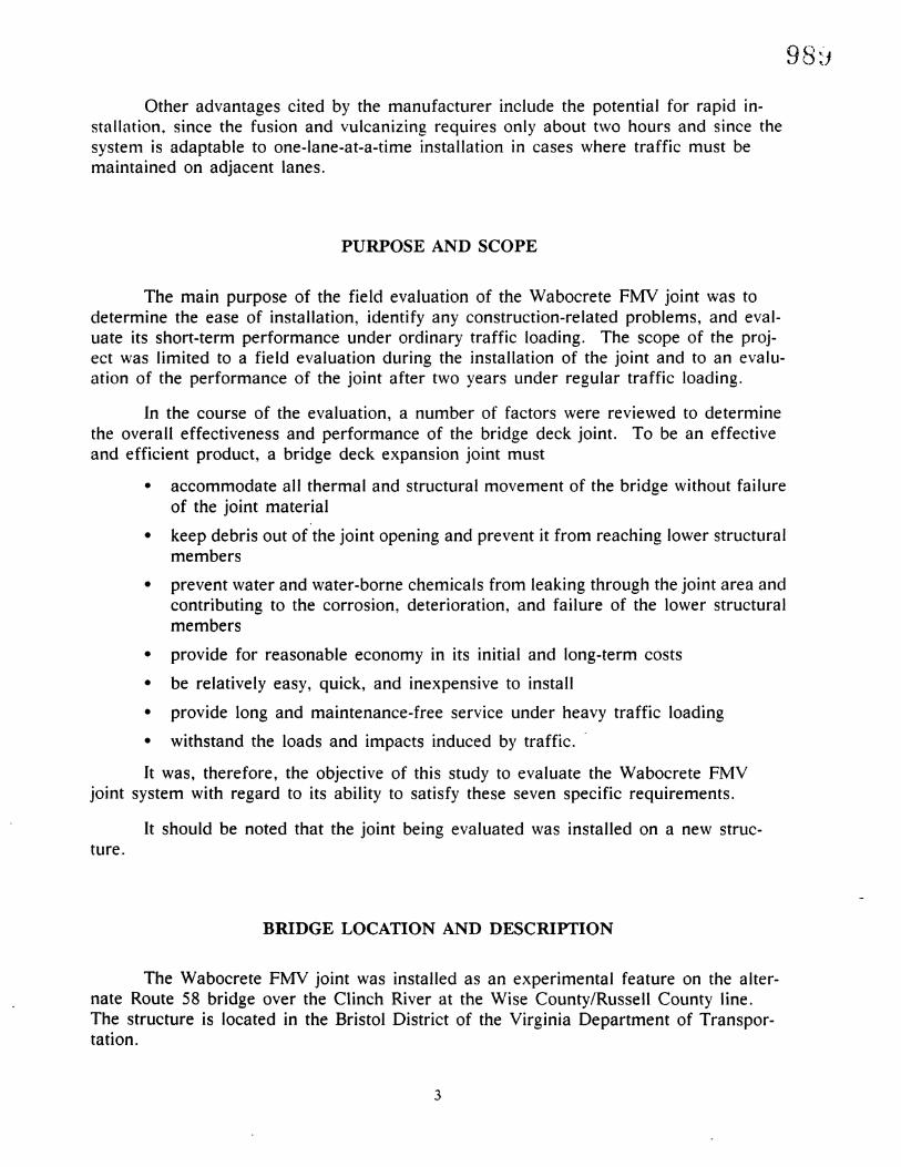
Other advantages cited by the manufacturer include the potential for rapid installntion, since the fusion and vulcanizing reqllires only about two hours and since thesysten1 is adaptable to one-Iane-at-a-time installation in cases where traffic must bemaintained on adjacent lanes.
PURPOSE AND SCOPE
The main purpose of the field evaluation of the Wabocrete FMV joint was todetermine the ease of installation, identify any construction-related problems, and evaluate its short-term performance under ordinary traffic loading. The scope of the project was limited to a field evaluation during the installation of the joint and to an evaluation of the performance of the joint after two years under regular traffic loading.
In the course of the evaluation, a number of factors were reviewed to determinethe overall effectiveness and performance of the bridge deck joint. To be an effectiveand efficient product, a bridge deck expansion joint must
• accommodate all thermal and structural movement of the bridge without failureof the joint material
• keep debris out of the joint opening and prevent it from reaching lower structuralmembers
• prevent water and water-borne chemicals from leaking through the joint area andcontributing to the corrosion, deterioration, and failure of the lower structuralmembers
• provide for reasonable economy in its initial and long-term costs
• be relatively easy, quick, and inexpensive to install
• provide long and maintenance-free service under heavy traffic loading
• withstand the loads and impacts induced by traffic.
It was, therefore, the objective of this study to evaluate the Wabocrete FMVjoint system with regard to its ability to satisfy these seven specific requirements.
It should be noted that the joint being evaluated was installed on a new struc-ture.
BRIDGE LOCATION AND DESCRIPTION
The Wabocrete FMV joint was installed as an experimental feature on the alternate Route 58 bridge over the Clinch River at the Wise County/Russell County line.The structure is located in the Bristol District of the Virginia Department of Transportation.
3

The bridge is composed of five continuous spans and one simple span. Twoexpansion joints are located on the bridge: one at abutment "A" on the west end ofthe bridge and another at pier No.5. The Wabocrete FMV joint is located at abutment "A" only. The deck length of the joint is 33 feet plus an additional amount thatturns up the face of each parapet wall.
EVALUATION PROCEDURES
The evaluation of a proprietary product such as the joint system in question isnormally an assessment of its ability to meet certain functional requirements and itsservice performance. Therefore, the main procedures used in this evaluation were inspections, observations, and record keeping during both the installation and performance phases of the study. Prior to installation of the joint, the various materials thatcomprise the total joint system were inspected as was the bridge deck area where thejoint was to be installed. Any deficiencies that \vere observed in either the product orthe bridge that might contribute to the integrity and performance of the joint systemwere noted. Similarly, the installation of the joint system was observed and notes weretaken regarding the installation procedure, problems encountered, time required tocomplete the various phases of the installation, and any other information that mighthave relevance to the performance of the system.
After the system was installed, it was once again inspected prior to the bridgebeing placed in service under ordinary traffic loading. Subsequently, the joint system\vas inspected three times with the maximum time period between inspections beingone year. Any abnormal conditions or other forms of distress that might have beenobserved during these inspections were noted. Primarily, however, the joint systemwas evaluated during the study period with respect to its ability to satisfy the primaryrequirements outlined earlier.
JOINT INSTALLATION
The joint system was installed in conformity with the manufacturer's specifications and recommended procedures; the manufacturer's materials were used.
All of the components of the joint system were delivered to the bridge site approximately two years prior to its actual installation. When the steel extrusion-sinusoidal anchorage system was inspected on November 4, 1986, it was badly corroded (seeFigures 2 and 3). The remaining elements of the system that were on the job sitewere ten 44-lb bags of premixed aggregate materials and several containers of the twocomponent Wabocrete FMV binder. In order to test the binder materials, small samples of each com,ponent were mixed by the joint manufacturer's representative and allowed to set overnight. The mixture hardened normally; thus,it was concluded that thematerials on hand could be used for the joint installation.
4
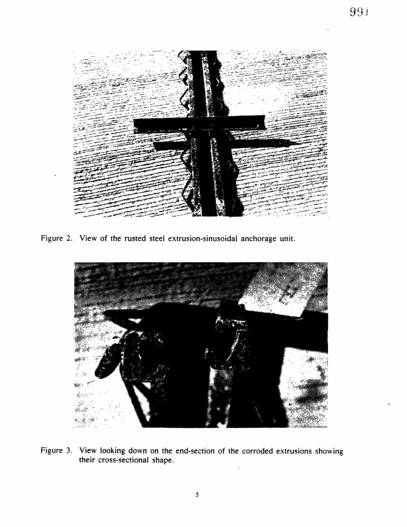
Figure 2. View of the rusted steel extrusion-sinusoidal anchorage unit.
Figure 3. View looking down on the end-section of the corroded extrusions showingtheir cross-sectional shape.
5

9 () /1..J 1--'
Prior to beginning the joint installation on November 6, 1986, the contractorsand-blasted the steel extrusion-sinusoidal anchorage system. Tn Figure 4, the cleanedunit is shown lying parallel to the bridge joint opening. Since there did not appear tobe any ill effects from the corrosion of the unit or from the cleaning operation, theunit was approved for installation on the bridge.
The blockout area was cleaned and dried with a propane torch, and styrofoam,shown lying next to the trough area in Figure 4, was inserted in the joint opening toprevent the FMV material from falling into the opening. The two components of thebinder material were placed in separate containers, which were, in turn, immersed inoil heated to 190 0 F. The two components were heated and maintained at 115 to 125 0
F until mixing began. The aggregates were heated to a warm condition and then mechanically mixed with the two-component resin to produce the Wabocrete FMV material.
~~:'. ~ Y, '"<;"::a1lIY <o~,.,..' ~
y' .. ',<0
Figure 4. View of the sinusoidal anchorage unit after sandblasting to remove rust.
With the steel extrusion unit placed in the blockout (Figure 5), the WabocreteFMV material was troweled into the cavity, and the surface area was smoothed. Thetrowels were heated with torches as necessary to prevent the binder from sticking tothem. As the surface was smoothed, heating ducts were moved into place in order tokeep heat on the material during curing. The heat was applied through the night byspace heaters placed at the ends of the ducts. Ordinarily, curing could be accomplished in approximately two hours by applying heat.
6

Figure 5. Workers aligning the joint hardware in the deck blackout. Cross angles areused for leveling the joint to proper elevation.
Figure 6. View of the joint after the binder had been placed in the blockout.
7

99~
At the olltset of the joint installation work, it \vas recognized that the 10 bags ofpremixed aggregates \vould be insufficient to complete the job. Conseqllently~ the contractor purchased additional aggregate to complete the last 6 ft of the joint on the eastside of the bridge. With the exception of the portions of the joint that turned up theface of the parapet wall, the installation was completed in approximately 4 hr. Therewas difficulty in placing the Wabocrete material up the face of the General Motorstype parapet wall because it tended to flow downward.
After the material was installed on the face of the parapets, the heat wasapplied to the entire joint system until the following morning. Although a strip offorming had been placed over the face of the joint that ran up the parapet wall, theWabocrete had continued to flow downward prior to solidifying. Consequently, it wasdecided that a small amount of material should be removed and replaced. This wasaccomplished by the contractor several days later without the assistance of the factoryrepresentatives. A view of the joint as it appeared the morning after the completion ofthe installation is shown in Figure 6. Subsequently, the neoprene strip seal was inserted into the steel extensions to complete the work.
During the day that the installation of the joint was taking place, the paintingsubcontractor was sandblasting the steel beams. As a result, there was considerabledust in the air and settling on the bridge deck surface while the joint installation wastaking place. Although the ,painting contractor moved his sandblasting operation to theopposite end of the bridge, there was still some dust in the work area. The dust was anuisance, but the factory representative did not feel that it would be detrimental to theinstallation of the joint as long as it was blown off the blockout surface prior to installation of the Wabocrete elastomeric concrete.
Other than the conditions described above, there were no apparent problemsduring installation that would likely contribute to a failure of the joint system.
The system appeared to be relatively quick and easy to install. With sufficientmaterials on the job site, the system could have been installed in several hours pluscuring time for the elastomeric binder material.
PERFORMANCE EVALUATION
The joint system was inspected again on May 5, 1987, prior to the bridge beingplaced in service. At this inspection, the joint appeared to be sound. Generally, noserious deficiencies were noted. On the face of one parapet wall, however, the bindermaterial had flowed downward leaving a gap at the upper end of the steel extrusions(Figure 7)0 There had been some effort to smooth the surface of the material to makeit flush with the face of the parapet wall.
Although appearance was affected, the performance of the joint has not beenaffected by this installation problem. The steel extrusion has begun to rust slightly,but this should polish off under traffic. There was a considerable amount of soil and
8
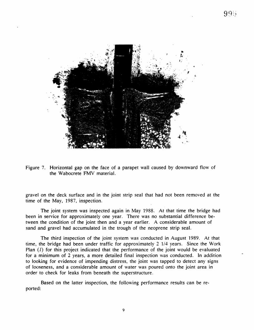
Figure 7. Horizontal gap on the face of a parapet wall caused by downward flow ofthe Wabocrete FMV material.
gravel on the deck surface and in the joint strip seal that had not been removed at thetime of the May, 1987, inspection.
The joint system was inspected again in May 1988. At that time the bridge hadbeen in service for approximately one year. There was no substantial difference between the condition of the joint then and a year earlier. A considerable amount ofsand and gravel had accumulated in the trough of the neoprene strip seal.
The third inspection of the joint system was conducted in August 1989. At thattime, the bridge had been under traffic for approximately 2 1/4 years. Since the WorkPlan (1) for this project indicated that the performance of the joint would be evaluatedfor a minimum of 2 years, a more detailed final inspection \vas conducted. In adclitionto looking for evidence of impending distress, the joint was tapped to detect any signsof looseness, and a considerable amount of water was poured onto the joint area inorder to check for leaks from beneath the superstructure.
Based on the latter inspection, the following performance results can be reported:
9
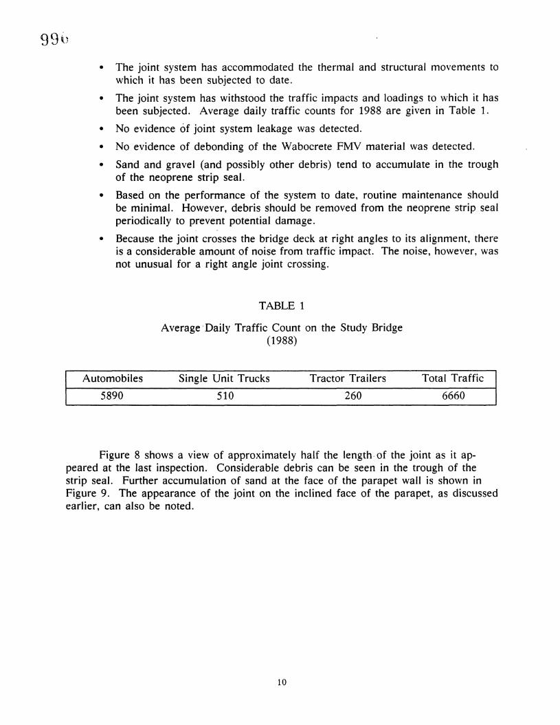
• The joint system has accommodated the thermal and structural movements towhicl1 it has been sllbjected to date.
• The joint system has withstood the traffic impacts and loadings to which it hasbeen subjected. Average daily traffic counts for 1988 are given in Table 1.
• No evidence of joint system leakage was detected.
• No evidence of debonding of the Wabocrete FMV material was detected.
• Sand and gravel (and possibly other debris) tend to accumulate in the troughof the neoprene strip seal.
• Based on the performance of the system to date, routine maintenance shouldbe minimal. However, debris should be removed from the neoprene strip sealperiodically to prevent potential damage.
• Because the joint crosses the bridge deck at right angles to its alignment, thereis a considerable amount of noise from traffic impact. The noise, however, wasnot unusual for a right angle joint crossing.
TABLE 1
Average 'Daily Traffic Count on the Study Bridge(1988)
Automobiles
5890
Single Unit Trucks
510
Tractor Trailers
260
Total Traffic
6660
Figure 8 shows a view of approximately half the length-of the joint as it appeared at the last inspection. Considerable debris can be seen in the trough of thestrip seal. Further accumulation of sand at the face of the parapet wall is shown inFigure 9. The appearance of the joint on the inclined face of the parapet, as discussedearlier, can also be noted.
10

Figure 8. Partial view of the joint, showing debris in the trough of the neoprene stripseal.
Figure 9. Sand accumulation at the face of the parapet wall.
11
99/

998
EVALUATIONS BY OTHER STATES.
Several Wabocrete FMV joint systems have been installed on bridges in Pennsylvania. In 1986, Knight (3) reported on an installation on a bridge deck reconstructionproject that incorporated two Wabocrete FMV joints. He noted that the elastomericconcrete was placed in 1 hour on the deck portion of each joint, and after a 5-hourcuring period, the bridge could have been opened to traffic if necessary. In laboratorytests conducted using the Wabocrete FMV resins to bond together two halves of a concrete cylinder, it was found that the material was stronger than the concrete. Pull-outtests and flexure tests conducted to check the material's bond strength also yieldedpositive results.
Another Pennsylvania installation on Route 1-70 was reported by Highlands (4)in February, 1987. In that installation, heat ducts were used to cure the elastomericmaterial because the joint was placed during cold weather. It was reported that theelastomeric concrete set in 2 hours by using the heat curing process.
Still another Pennsylvania installation was reported upon by Arellano (5) in February, 1988. This installation is also on Route 1-70 near the one reported by Highlands. The Wabocrete FMV, which is installed on the westbound lane, is being evaluated along with a similar system called Ceva Crete 300 that is installed on theeastbound ·lane. Workers reported that the Wabocrete FMV material was easier to install than the Ceva Crete.
The Pennsylvania installations are to be evaluated for 5 years. They were reported to be performing well in September, 1988.
Extensive testing of four different brands of elastomeric concrete has been conducted by Price (6). Twelve tests were used to evaluate the binder materials and fivewere used to evaluate the binder-aggregate materials. From the results of these tests,specifications were developed to provide for a material with good flexibility and bonding characteristics.
RETROFIT INSTALLATIONS IN VIRGINIA
Although not a part of this evaluation, the writer discovered in mid-1989 thatthe Wabocrete FMV joint system had been installed at two bridge sites (four bridges)on the Capital Beltway. At one of the two sites, route 1-495 crosses Scott's Run in thenorthwest section of the Beltway, and at the other, route 1-95 crosses the RF&P Railroad east of the intersection of routes 1-95 and 1-395. On the latter site, it was reported by the district bridge engineer that approximately 900 ft of the jOillt were installed in November 1988 on the two four-lane bridges. By May 1989, it wasestimated from sounding tests that 25 to 30 percent of the total joint length had debonded.
At each of the bridge sites, the Wabocrete joints were installed over the existingjoint openings. The pavement adjacent to the joint material was an asphaltic overlay.
12
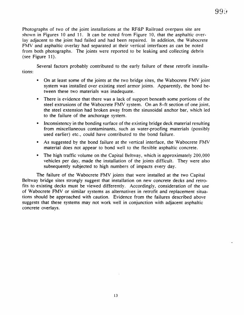
Photographs of two of the ~oint installations at the RF&P Railroad overpass site aresho\vn in Figures 10 and 11. It can be noted from Figure 10, that the asphaltic overlay adjacent to the joint had failed and had been repaired. In addition, the WabocreteFMV and asphaltic overlay had separated at their vertical interfaces as can be notedfrom both photographs. The joints were reported to be leaking and collecting debris(see Figure 11).
Several factors probably contributed to the early failure of these retrofit installa-tions:
• On at least some of the joints at the two bridge sites, the Wabocrete FMV jointsystem was installed over existing steel armor joints. Apparently, the bond between these two materials was inadequate.
• There is evidence that there was a lack of support be-neath-some portions of thesteel extrusions of the Wabocrete FMV system. On an 8-ft section of one joint,the steel extension had broken away from the sinusoidal anchor bar, which ledto the failure of the anchorage system.
• Inconsistency in the bonding surface of the existing bridge deck material resultingfrom miscellaneous contaminants, such as water-proofing materials (possiblyused earlier) etc., could have contributed to the bond failure.
• As suggested by the bond failure at the vertical interface, the Wabocrete FMVmaterial does not appear to bond well to the flexible asphaltic concrete.
• The high traffic volume on the Capital Belt\vay, which is approximately 200,000vehicles per day, made the installation of the joints difficult. They were alsosubsequently subjected to high numbers of impacts every day.
The failure of the Wabocrete FMV joints that were installed at the two CapitalBeltway bridge sites strongly suggest that installation on new concrete decks and retrofits to existing decks must be viewed differently. Accordingly, consideration of the liseof Wabocrete FMV or similar systems as alternatives in retrofit and replacement situations should be approached with caution. Evidence from the failures described abovesuggests that these systems may not work well in conjunction with adjacent asphalticconcrete overlays.
13

Figure 10. View of a Wabocrete F1VIV retrofit installation on a Capital Beltway bridgedeck.
Figure 11. Separation at the interface between the joint and adjacent asphalt overlay.
14

1.0()J
SUMMARY AND CONCLUSIONS
Installation
The Wabocrete FMV joint system appears to be relatively quick and easy to in-> stall assuming all the needed materials, equipment and manpower are available and
the operation is properly planned. Placing the Wabocrete material on an inclined faceis difficult since it tends to flow downward.
The system offers some advantages over the mechanically anchored preformedjoint systems. First, the blockout for the joint does not have to be precisely dimensioned or have smooth surfaces since the Wabocrete FMV material is placed while it isplastic. Secondly, the steel extrusions and anchorage system can be leveled to theproper elevation and position prior to placement of the Wabocrete FMV material.Therefore, the elevation of the bottom of the blockout is not as crucial as it would befor a preformed system. Thirdly, with no anchor bolts involved in the Wabocrete FMVsystem, the time, effort, and errors involved in placing anchor bolts are eliminated.Accordingly, potential anchor bolt failure problems are eliminated.
Service Performance
After approximately 2 1/4 years of service, the Wabocrete FMV joint system hasperformed well on the alternate Route 58 bridge over the Clinch River. Throughoutthis period of service, the joint system has accommodated all thermal and structuralmovements, withstood the traffic impacts of approximately 6700 vehicles per day (including 12% trucks), remained leakproof, and has not debonded. The joint does tendto collect sand and gravel in the trough of the neoprene strip seal. This could be detrimental over a period of time-particularly if sharp debris such as glass or metal became wedged in the trough. The debris observed in the joint during the inspections,however, did not appear to have caused any problems.
The joint does produce considerable noise from traffic impact. The noise, however, seems no greater than that resulting from similar joints crossing a bridge deck atright angles to the flow of traffic.
To date, the service performance of several installations in Pennsylvania hasbeen quite similar to that observed in this study.
Retrofit Performance
Though not a part of the original evaluation covered by this project, the Wabocrete FMV joints installed at two bridge sites on the Capital Beltway were inspected.These joints, which were installed as retrofits to the existing bridges, have performedpoorly. At one of the bridge sites, joints installed in November 1988 had exhibited
15
substantial debonding as well as other problems by May 1989. The failure of theseinstallations strongly suggest that application of the Wabocrete FMV and other similarsystems as retrofits must be viewed differently from applications to new construction.Evidence from the failures described in this report indicate that the Wabocrete FMV,and probably similar systems, may not perform well when used in conjunction with adjacent asphaltic concrete overlays.
RECOMMENDATIONS
The performance of the Wabocrete FMV joint system installed on the alternateRoute 58 bridge over the Clinch River does not give any reason to suggest that thejoint not be used on similar new structures having moderate rural traffic volumes. Itshould be noted, however, that this performance evaluation has covered only slightlymore than 2 years. The joint should be inspected periodically in the future to bettergage its performance.
When using the Wabocrete FMV material on an inclined face, a stiffer mix and/or forming of the face should be used to minimize flowdown.
Because of the tendency of this joint to accumulate debris in the trough of theneoprene strip seal, it should be routinely cleaned-perhaps semi-annually or as necessary.
The use of the Wabocrete FMV and similar systems as retrofit on older bridgesshould be approached with caution. Furthermore, these systems should probably notbe used in retrofit situations in conjunction with adjacent asphaltic overlays.
16
REFERENCES
1. Hilton, M. H. 1984. Work Plan: Field evaluation of the Wabocrete FMVexpansionjoint for bridge decks. VHTRC Work Plan No. 84-WP17. Charlottesville, Va.: Virginia Transportation Research Courrcil
2. Burke, Martin P., Jr. 1989. Bridge Deck Joints. National Cooperative High\vay Research Program Synthesis of Highway Practice, Report #141, Transportation Research Board,
3. Knight, Norman E. 1986. Construction Report: Field evaluation of Wabocrete FMVexpansion dam systems. Research Project 83-40. PennDOT, Report No. FHWAPA-85-027.
4. Highlands, Keith L. 1987. Construction Report: Field evaluation of Wabocrete FMVexpansion dam system. Research Project 83-40. PennDOT. Report No. FHWAPA-86-033.
5. Arellano, Janice L. 1988. Construction Report: Field evaluation of Wabocrete FMVand Ceva Crete 300 expansion dam systems. Project 83-40. PennDOT. Report No.FHWA-PA-87-017.
6. Price, Robert K. 1985. Evaluation of elastomeric concrete for use as an expansionjoint nosing material. Project 3-C-5-122. Austin, Texas: Texas Department ofPublic Transportation.
17


ACKNOWLEDGElVIENTS
The author thanks Jimmy French, Technical Program Supervisor, for his assistance in conducting the field evaluations associated with this study. The author thanksH. E. Brown, K. H. McGhee, and W. T. McKeel for their revie\Y and comments on thisreport.
This study was sponsored by the Virginia Transportation Research Council, directed by Dr. G. R. Allen, and the Federal Highway Administration.
19

II
I
I
I
I
I
II
I
I
I
I
I
II
I
II
I
I
I
I
I
II
I
I
I
I
II
I
I
I
I
I
I
I
I
II
I
I
I
I
I
II
I
I
I
I
I
II
I
II
I