1 (accepted by sensors spectalk: conforming iot
TRANSCRIPT

Sensors 2020, 20, x; doi: FOR PEER REVIEW www.mdpi.com/journal/sensors
(Accepted by Sensors) 1
SpecTalk: Conforming IoT Implementations to Sensor Specifications 2
Yi-Bing Lin1,3,4,*, Sheng-Lin Chou2 , Ted C.-Y. Chang 5 and Yun-Wei Lin 6 3
4
1 School of Computing, National Cheng Kung University, Taiwan; 5 2 Information and Communication Research Laboratories, Industrial Technology Research Institute, Taiwan; 6
[email protected]; 7 3 College of Humanities and Sciences, China Medical School, Taiwan; 8 4 College of Artificial Intelligence, National Yang Ming Chiao Tung University, Taiwan; [email protected] 9 5 Quanta Computer, Taiwan; [email protected] 10 6 College of Artificial Intelligence, National Yang Ming Chiao Tung University, Taiwan; [email protected] 11
12 * Correspondence: [email protected]; 13
Received: date; Accepted: date; Published: date 14
Abstract: Due to the fast evolution of Sensor and Internet of Things (IoT) technologies, several 15 large-scale smart city applications have been commercially developed in the recent years. In these 16 developments, the contracts are often disputed in the acceptance due to the fact that the contract 17 specification is not clear, resulting in a great deal of discussion of the gray area. Such disputes often 18 occur in the acceptance processes of smart buildings, mainly because most intelligent building 19 systems are expensive and the operations of the sub-systems are very complex. This paper 20 proposes SpecTalk, a platform that automatically generates the code to conform IoT applications to 21 the Taiwan Association of Information and Communication Standards (TAICS) specifications. 22 SpecTalk generates a program to accommodate the application programming interface of the IoT 23 devices under test (DUTs). Then the devices can be tested by SpecTalk following the TAICS data 24 formats. We describe three types of tests: self-test, mutual-test and visual test. A self-test involves 25 the sensors and the actuators of the same DUT. A mutual-test involves the sensors and the 26 actuators of different DUTs. A visual-test uses a monitoring camera to investigate the actuators of 27 multiple DUTs. We conducted these types of tests in commercially deployed applications of smart 28 campus constructions. Our experiments in the tests proved that SpecTalk is feasible and can 29 effectively conform IoT implementations to TACIS specifications. We also propose a simple 30 analytic model to select the frequency of the control signals for the input patterns in a SpecTalk test. 31 Our study indicates that it is appropriate to select the control signal frequency such that the 32 inter-arrival time between two control signals is larger than 10 times of the activation delay of the 33 DUT. 34
35
Keywords: Acceptance test, Internet of Things (IoT), IoT specification, smart building, sensor, 36 Taiwan Association of Information and Communication Standards (TAICS) 37
38
1. Introduction 39
Many smart applications have been developed with Internet of Things (IoT) technology [1] [2] 40 in large-scale smart city constructions. However, contracts of intelligent application constructions 41 are often disputed in the acceptance due to the fact that contract specifications are not clear. The 42 higher the level of intelligence, the greater the controversy especially when the customers and the 43 vendors that provide the solutions have different imaginations about the functionality of smart 44 products. Such disputes often occur during the acceptance processes of smart buildings, mainly 45

Sensors 2020, 20, x FOR PEER REVIEW 2 of 25
because intelligent building systems are expensive and the operations of the sub-systems are very 46 complex due to the fast evolution of IoT technology. 47
According to Allied Market Research [3], the smart building market will reach 35 billion USD by 48
2020, with a compound annual growth rate of about 30 per cent, driven by advances in the IoT and 49
sensor networks [4]. A smart building typically includes different subsystems in the same building 50
[5]. To effectively integrate and connect the subsystems, a major challenge is the deployment of the 51
Information and Communication Technology (ICT) common trench to satisfy the needs for 52
intelligent building system integration. These needs make it difficult for traditional contracts to 53
standardize specific acceptance methods. 54
55
The classical method in contract law established a formula for quotation and acceptance in the 19th 56
century, allowing buyers and sellers to reach a consensus on contracts. Formal tests of customer 57
requirements and business processes are typically carried out at the time of acceptance to determine 58
whether the system meets the acceptance criteria and to enable the customer to decide whether or 59
not to accept the system [6]. Flexible intelligent systems contracted in the traditional way are likely 60
to be controversial for misleading conduct and misrepresenting the right to accept. This 61
phenomenon becomes more obvious as the intelligence elasticity of the products increases in the era 62
of rapidly evolving ICT. 63
Interestingly enough, acceptance tests for complicated mobile systems have been well conducted. 64
In mobile telecommunications systems, data formats and communication protocols are defined by 65
standard organizations such as European Telecommunications Standards Institute (ETSI) and 3GPP. 66
Following their specifications, developed systems can be systematically tested. For example, 67
Testing and Test Control Notation (TTCN) has been used to transplant the layer-3 functions in 5G 68
and LTE protocol stacks to carry out test instruments. In [24] an implementation scheme of terminal 69
Radio Resource Management conformance test system was implemented with TTCN-3, and the 70
feasibility of this scheme was verified by running the designed test cases. To speed up TTCN-3 test 71
system testing, a tool was created to visualize large test systems [25][26]. This tool was use to 72
analyze all standardized test suites available at www.ttcn3.org, finding circular dependency and 73
unnecessary source files in almost every test suite. 74
Unfortunately, there are no comparable globally accepted specifications for smart applications. In 75
[27], Cucumber and Selenium were used to automate testing activity for a system-level test on 76
well-known platforms such as SOASTA (Android) and Ranorex (iOS). The authors pointed out the 77
difficulties in establishing compatibility with all smart applications due to inconsistent data formats, 78
noting that it is challenging to ensure compatibility with much variability of the application 79
platforms. 80
Similarly, the study in [28] investigated model-based software tests by using the Selenium library 81
with the Graph Walker tool, which outperforms traditional software tests where JUnit and TestNG 82
libraries were used. Comparisons of these two methods were performed and reported on 83
parameters of code line number, actual error detection rate, and test run time parameters. At the 84
smart application level, model-based software tests cannot be conducted due to inconsistent data 85

Sensors 2020, 20, x FOR PEER REVIEW 3 of 25
formats. Therefore, acceptance tests of intelligent systems (smart applications) are difficult because 86
there are no globally accepted standards to specify these systems. 87
At present, intelligent system related standards, including building automation and energy-based 88
air conditioning [7][19], have gradually involved advanced networking and IoT technologies. Since 89
multiple systems with different communication protocols [8] [9] [10] and data formats [11] [12] are 90
often developed in a building, the matter of how to integrate the various systems and collect the 91
required information is a key factor in managing building intelligence. At this stage, the market has 92
a variety of intelligent energy management systems, independent intelligent building subsystems 93
and data format interfaces. It is difficult to incorporate various independent subsystems for overall 94
monitoring and management, which affects the open and common development for future 95
intelligent networking to heterogeneous services in smart buildings. 96
97
In light of the application situation and demand for intelligent building energy management system, 98
Taiwan Association of Information and Communication Standards (TAICS) specifies the data format 99
standard of intelligent building [19], which is applicable to the data exchange between the 100
subsystems and the devices under the integrated system monitoring platform or the integrated 101
operation center (IOC). However, most vendors are unable to study TAICS specifications carefully 102
and provide Application Programming Interface (API) software that conforms to TAICS 103
specifications. When customers request to follow TAICS standard, vendors may significantly 104
increase the price, causing more controversy. Therefore, we design SpecTalk, an interface code 105
generation system that makes it easy for the vendors to automatically interwork their intelligent 106
systems to the TAICS specification-compliant platform for acceptance tests. SpecTalk does not 107
involve data exchange within subsystems or devices. Vendors can easily integrate the APIs of their 108
systems to the TAICS test system by using SpecTalk's Graphical User Interface (GUI). The paper is 109
organized as follows. Section 2 introduces TAICS; Section 3 proposes SpecTalk; Section 4 describes 110
how SpecTalk is used to conduct three types of acceptance tests; Section 5 proposes an analytic 111
model to select the frequency of the control signals in the input pattern of a IoT device test. 112
113
2. Taiwan Association of Information and Communication Standards 114
To highlight the state-of-the-art sensor technology in Taiwan, it is important to introduce the sensor 115
standard efforts promoted by the Ministry of Economic Affairs (MOEA). In Taiwan, MOEA is in 116
charge of the 5G/IoT development. For 5G/IoT specification promotion, the mission is carried out by 117
Taiwan Association of Information and Communication Standards (TAICS) sponsored by MOEA. 118
TAICS is an industry organization founded in June 2015 with the members from industry, research 119
and academia organizations in Taiwan. TAICS bridges the local industry with global standard 120
initiatives/organizations by contributing the study results or consolidated consensus, and also 121
develop the local standard or study report per request. TAICS is open to participation from all the 122
companies/organizations with divisions in Taiwan. Seven technical committees (TCs) have been 123
chartered focusing on 124
• Advanced Mobile Communication 125

Sensors 2020, 20, x FOR PEER REVIEW 4 of 25
• Network Communication 126
• Device Internetworking 127
• Audiovisual Services and Communications 128
• Network and Information Security 129
• Intelligent Buildings ICT 130
• Internet of Vehicles (IoV) & Automated Driving 131
In Taiwan, most solution providers deliver quick and cheap IoT application constructions (such as 132
smart building, smart agriculture, smart manufacture, and so on) to the customers without 133
conforming to any standards. To resolve this issue, This paper proposes SpecTalk, a tool that can 134
automatically generate an interface for any IoT application to conform to the TAICS specifications. 135
SpecTalk has been developed by Accton (one of the largest ICT companies in Taiwan, Revenue USD 136
1.85 Billion in 2020), and aims to become the standard interworking mechanism of TAICS. SpecTalk 137
is being used to produce receiving reports for the following smart park constructions: 138
139
• Hsinchu International AI Smart Park (Fig. 11) 140
• Smart Campus of China Medical University in Shuinan Trade and Economic Park, Taichung (Fig. 141
12) 142
SpecTalk also aims to regulate agriculture related data for the Council of Agriculture, Taiwan. we 143
will use SpecTalk to interwork with the specifications of the following international partners: 144
• The Telecommunication Technology Committee (TTC), Japan 145
• The Telecommunications Industry Association (TIA), USA 146
• Institute of Electrical and Electronics Engineers (IEEE), USA 147
• China Communications Standards Association (CCSA), China 148
• European Telecommunications Standards Institute (ETSI), EU 149
• The Association of Radio Industries and Businesses (ARIB), Japan 150
• Telecommunications Standards Development Society (TSDSI), India 151
• Malaysian Technical Standards Forum Bhd (MTSFB), Malaysia 152
• Telecommunications Technology Association (TTA), Korea 153
3. The SpecTalk Architecture and Procedures 154
All IoT-related specifications characterize an IoT device with the following fields as illustrated in 155
Fig. 1: (1) device type or device model (DM; e.g., Generator); (2) device ID (e.g., GEN-{NNNN} 156
for a generator) and the description for the device features (DFs) including (3) DF name in 157
Chinese; (4) DF name (e.g., tankOilLevelStatus); (5) DF abbreviation (e.g., oilSts); (6) I/O (input 158
or output); (7) DF parameter (e.g., status with the states {NORMAL, LOW}). 159

Sensors 2020, 20, x FOR PEER REVIEW 5 of 25
160
Fig. 1. The TAICS specification for “Generator”. the Chinese descriptions are translated to English as 161 follows: 裝置 ID (device ID), 裝置類別(device type), 短名稱 (DF name, see (1)), 監控標示 (DF 162
type ; see (2)), 預設單位/列舉值集(parameter type ; see (4)), 中文名稱 (Chinese name; see (5)), 長名163
稱(Long Name; see (6)) 164
The SpecTalk platform consists of five components: Device Feature Management (Fig. 2 (2)), 165
SpecTalk Database (Fig. 2. (3)), Device Model Management (Fig. 2 (4)), Device Application 166
Generation (Fig. 2 (5)) and Test Engine (Fig. 2 (8)). 167
168
Fig. 2. The SpecTalk approach to test an IoT device with TAICS specification. 169
170
From the specification of an IoT device (Fig. 2 (1)), we store its software configuration in the 171
SpecTalk Database (Fig. 2 (3)). The configuration is used to automatically cerate the Sensor & 172
Actuator application (SA) interface (Fig. 2 (6)) that binds the IoT device under test (DUT; Fig. 2 173
SA
Interface
Device
Feature
Management
SpecTalk
DataBase
Device
Model
Management
Test
Configuration
Device
Application
Generation
Test
ProceduresTest
Report
Test Engine
Sensor
Specification421
53
6
89
7

Sensors 2020, 20, x FOR PEER REVIEW 6 of 25
(7)) to Test Engine (Fig. 2 (8)). The SpecTalk Database will be maintained in a neutral third party 174
(for example, TAICS) and can be freely accessed by both the buyers and sellers to create their 175
contracts and acceptance test procedures for IoT applications. 176
3.1. Construction of the SpecTalk Database 177
SpecTalk is a web-based platform, which can be operated in any computing device with a 178
browser (for example, a smartphone). In this platform, the configurations of IoT devices are 179
stored in the SpecTalk Database through a web-based Device Feature window. We first create 180
and store all DFs of an IoT device using the Device Feature Management (Fig. 2 (2)). Consider 181
the tank oil level status as an example. We first fill the DF name “oilSts-I” (Fig. 3 (1)), then we 182
select the DF type as “IDF” (Fig. 3 (2)). Note that the DF name is appended with “-I” if it is an 183
IDF, and is appended with “-O” if it is an output device feature (ODF). The category field is 184
filled with the number of the specification TS-0022 (Fig. 3 (3)). There is one parameter of type 185
“Boolean” to represent the status of the oil level (Fig. 3 (4)). We put extra information about the 186
DF in the description window (Fig. 3 (5) and (6)). After the DF information filling is complete, 187
the oilSts DF configuration is saved in the SpecTalk Database. 188
189
190
(1.2) Fig. 3. Device Feature (DF) Creation. 191
192
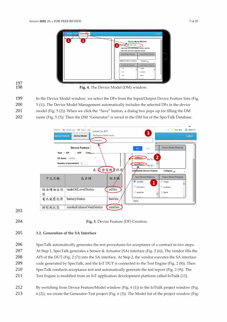
We create the DM of the IoT device using the Device Model Management by clicking “Device 193
Model” (Fig. 4 (2)). Then we jump from Device Feature window (Fig. 4 (1)) to Device Model 194
window (Fig. 4 (3)). 195
196
TS-0022
1 2
3
45 6
oilSts-I
Sensors 2020, 20, x FOR PEER REVIEW 7 of 25
197 Fig. 4. The Device Model (DM) window. 198
In the Device Model window, we select the DFs from the Input/Output Device Feature lists (Fig. 199
5 (1)). The Device Model Management automatically includes the selected DFs in the device 200
model (Fig. 5 (2)). When we click the “Save” button, a dialog box pops up for filling the DM 201
name (Fig. 5 (3)). Then the DM “Generator” is saved in the DM list of the SpecTalk Database. 202
203
Fig. 5. Device Feature (DF) Creation. 204
3.2. Generation of the SA Interface 205
SpecTalk automatically generates the test procedures for acceptance of a contract in two steps. 206
At Step 1, SpecTalk generates a Sensor & Actuator (SA) interface (Fig. 2 (6)). The vendor fills the 207
API of the DUT (Fig. 2 (7)) into the SA interface. At Step 2, the vendor executes the SA interface 208
code generated by SpecTalk, and the IoT DUT is connected to the Test Engine (Fig. 2 (8)). Then 209
SpecTalk conducts acceptance test and automatically generate the test report (Fig. 2 (9)). The 210
Test Engine is modified from an IoT application development platform called IoTtalk [13]. 211
By switching from Device Feature/Model window (Fig. 6 (1)) to the IoTtalk project window (Fig. 212
6 (2)), we create the Generator-Test project (Fig. 6 (3)). The Model list of the project window (Fig. 213
1 2
3
1
2
3
oilSts-I
ventSts-I

Sensors 2020, 20, x FOR PEER REVIEW 8 of 25
6 (4)) provides the device model indexes stored in the SpecTalk Database. When we select 214
“Generator” (Fig. 6 (5)), the Generator window pops up. The features of vendor’s generator are 215
a subset of the Generator device model. Therefore, SpecTalk allows selection of the DF number 216
to set up the actual configuration of the generator under test (Fig. 6 (6)). After we save the 217
setups (Fig. 6 (7)), the graphical representation of the generator under test is shown in the 218
project window (Fig. 6 (8)). We can click the DF icon (Fig. 6 (9)) and further set up the 219
parameters of the DF, e.g., the max and the min values of the DF (Fig. 6 (10)). 220
221
Fig. 6. Specifying the generator under test. 222
223
Fig. 7. Automatic generation of the codes for the DA and the SA interface. 224
225
12
3 4
5
6
7
8
9
10battSts-I
oilSts-I
ventSts-I
battSts-I
oilSts-I
ventSts-I
Device Application
(DA)
Sensor&Actuator
Application (SA)
Interface
Display
2
3
4
1 battSts-I
oilSts-I
ventSts-I
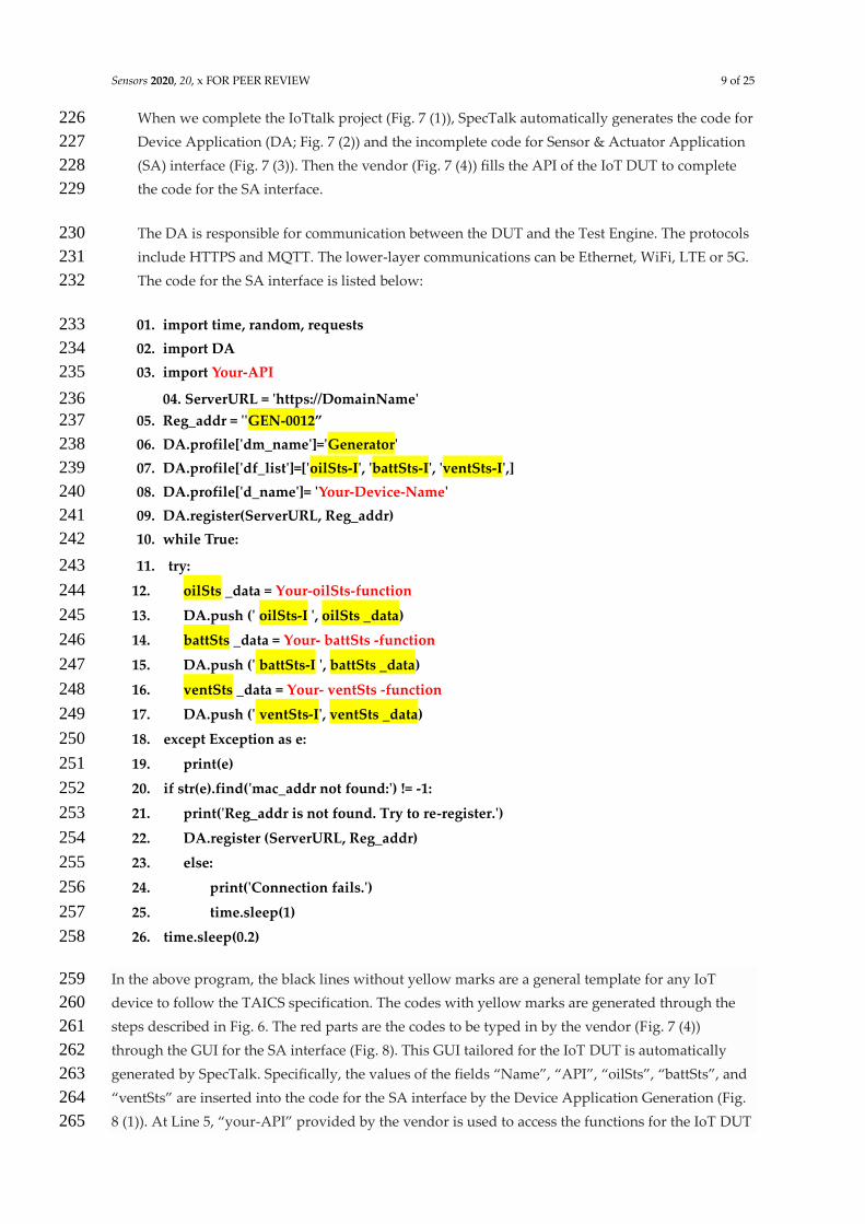
Sensors 2020, 20, x FOR PEER REVIEW 9 of 25
When we complete the IoTtalk project (Fig. 7 (1)), SpecTalk automatically generates the code for 226
Device Application (DA; Fig. 7 (2)) and the incomplete code for Sensor & Actuator Application 227
(SA) interface (Fig. 7 (3)). Then the vendor (Fig. 7 (4)) fills the API of the IoT DUT to complete 228
the code for the SA interface. 229
The DA is responsible for communication between the DUT and the Test Engine. The protocols 230
include HTTPS and MQTT. The lower-layer communications can be Ethernet, WiFi, LTE or 5G. 231
The code for the SA interface is listed below: 232
01. import time, random, requests 233
02. import DA 234
03. import Your-API 235
04. ServerURL = 'https://DomainName' 236
05. Reg_addr = ''GEN-0012” 237
06. DA.profile['dm_name']='Generator' 238
07. DA.profile['df_list']=['oilSts-I', 'battSts-I', 'ventSts-I',] 239
08. DA.profile['d_name']= 'Your-Device-Name' 240
09. DA.register(ServerURL, Reg_addr) 241
10. while True: 242
11. try: 243
12. oilSts _data = Your-oilSts-function 244
13. DA.push (' oilSts-I ', oilSts _data) 245
14. battSts _data = Your- battSts -function 246
15. DA.push (' battSts-I ', battSts _data) 247
16. ventSts _data = Your- ventSts -function 248
17. DA.push (' ventSts-I', ventSts _data) 249
18. except Exception as e: 250
19. print(e) 251
20. if str(e).find('mac_addr not found:') != -1: 252
21. print('Reg_addr is not found. Try to re-register.') 253
22. DA.register (ServerURL, Reg_addr) 254
23. else: 255
24. print('Connection fails.') 256
25. time.sleep(1) 257
26. time.sleep(0.2) 258
In the above program, the black lines without yellow marks are a general template for any IoT 259
device to follow the TAICS specification. The codes with yellow marks are generated through the 260
steps described in Fig. 6. The red parts are the codes to be typed in by the vendor (Fig. 7 (4)) 261
through the GUI for the SA interface (Fig. 8). This GUI tailored for the IoT DUT is automatically 262
generated by SpecTalk. Specifically, the values of the fields “Name”, “API”, “oilSts”, “battSts”, and 263
“ventSts” are inserted into the code for the SA interface by the Device Application Generation (Fig. 264
8 (1)). At Line 5, “your-API” provided by the vendor is used to access the functions for the IoT DUT 265

Sensors 2020, 20, x FOR PEER REVIEW 10 of 25
(Lines 12, 14, and 16). The complete code for the SA interface (Fig. 8 (2)) is saved in the file 266
“File-for-SA-code” specified in Fig. 8 (3). Note that when a DF is created in Fig. 3, the DF is used to 267
build the device model in TAICS. Specifically, a DM and its DFs are created for TAICS specification, 268
and every “real” vendor device is a subset of the TAICS DM and may not have all device features 269
specified in the TAICS DM. The actual features of the DUT are actually mapped to SpecTalk 270
through the procedure in Fig. 8. In the current implementation, Python, Java, Javascript, and C 271
versions the SA interface codes are available in SpecTalk. 272
273
274
Fig. 8. Binding the DUT and SpecTalk by creating the SA interface of “Generator”. 275
At the side of the IoT DUT, the vendor executes the SA interface code (Fig. 9 (1)) that registers 276
the device to the Test Engine (Fig. 9 (2)). The Test Engine retrieves the configuration of the IoT 277
DUT from SpecTalk Database (Fig. 9 (3)), and executes the test procedures to generate the test 278
report. 279
280
Fig. 9. The SpecTalk test process. 281
A test procedure can be easily created as an IoTtalk project. A simple example is described as 282
follows. From the Model list (Fig. 10 (1)), we select “Generator” and “Display” (Fig. 10 (2)). 283
Display prints out whatever data it receives. By dragging a line between “ventSts-I” (Fig. 10 (3)) 284
Your-Device-Name
Your-oilSts-function
Your-battSts-function
Your-ventSts-function
Name
oilSts
battSts
ventSts
Generator
Your-APIAPI
File-for-SA-codeFileSave Delete
Line 8
Line 5
Line 12
Line 14
Line 16
SA
Interface
Device
Application
Generation
1
3
2
SA Interface
SpecTalk
DataBase
Test
Engine
1Test
Report
SpecTalk Server
2
3
Device under Test

Sensors 2020, 20, x FOR PEER REVIEW 11 of 25
to “Controller-O”, the data will be delivered by this link (Join 2). To make sure this test 285
procedure behaves correctly, we click the “Simulation” button (Fig. 10 (4)). Following random 286
number generation simulation [15][16] or trace-driven emulation [14], the test results are shown 287
in the Monitor window (Fig. 10 (5)). 288
289
290
Fig. 10. A simple SpecTalk test procedure. 291
3. The SpecTalk Acceptance Tests 292
Three types of SpecTalk tests can be developed following the test procedure creation process 293
similar to the one in Fig. 10. 294
• Self-test involves the IoT DUT only 295
• Mutual-test involves two or more IoT DUTs 296
• Visual-test involves the IoT DUTs and a monitoring camera 297
In this section, we provide several examples to show how SpecTalk works. 298
3.1. Self-Test 299
Hsinchu County is developing the Hsinchu International AI Smart Park (Fig. 11), which is 300
managed by Accton. SpecTalk will be used by Accton to verify all smart applications in the 301
park. Most of them will be achieved through self-tests. Another example is the smart campus of 302
China Medical University (CMU) in Shuinan Trade and Economic Park, Taichung (Fig. 12). In 303
this subsection, we use the generator and the water-cooled chiller of the CMU smart campus as 304
examples to show how to conduct self-test. 305
3
1
2
4
5
battSts-I
oilSts-I
ventSts-I
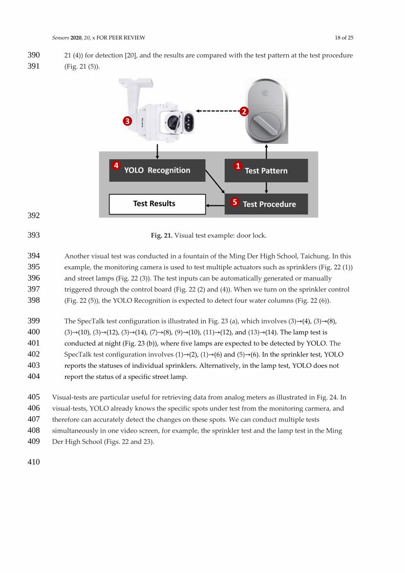
Controller-O

Sensors 2020, 20, x FOR PEER REVIEW 12 of 25
306
Fig. 11. Hsinchu International AI Smart Park. 307
308
Fig.12. The generator units in the smart buildings of China Medical University in Shuinan 309
Trade and Economic Park, Taichung. 310
In the IoTtalk window, we create a project “Self-Test”. Besides the three IDFs we created in Fig. 311
6 (see Fig. 13 (5), (7) and (9)), we also create two output device features (ODFs): the power 312
switch of the generator “Gen-Switch-O” (Fig. 13 (2)) and the power switch of the smoke exhaust 313
ventilator “Vent-Switch-O” (Fig. 13 (4)). In the emulation mode, SpecTalk automatically 314
generates the control signals through IDFs Switch-I1 and Switch-I2 (Fig. 13 (1) and (3)) to turn 315
Gen-Switch-O and Vent-Switch-O on and off. Switch-I1 turns on the generator to see if both the 316
battery level and oil consumption increase. The validation is performed by Test Output through 317
battSts-O, oilSts-O and Switch-O1 (Fig. 13 (6), (8) and (11)). Switch-I2 tests if ventSts-I correctly 318
indicates the ventilator operation. The validation is performed by Test Output through 319
ventSts-O and Switch-O2 (Fig. 13 (10) and (12)). In the SpecTalk emulation, “Test Inputs” 320
automatically generates sequences of test signals through random number generators. We can 321
also use pre-stored test vectors as inputs sent to the Test Engine. The test procedure is 322
Generator units

Sensors 2020, 20, x FOR PEER REVIEW 13 of 25
developed manually through the IoTtalk GUI (which minimizes the programing effort) at the 323
first time. Then the procedure is saved in SpecTalk to be reused for similar test cases in the 324
future. Suppose that the oil consumption rate is given in the vendor’s data sheet. If the tank is 325
full, then it will be consumed below the threshold in, for example, 50 minutes. Then the test 326
procedure will check if oilSts-I gives an alert after 50 minutes. 327
328
Fig. 13. Self-test configuration for the generator. 329
Another example is the self-test configuration for water-cooled chiller. In the TAICS 330
specification, there is a two-parameter IDF “chWF-I” to indicate the water flow of the chiller. 331
The IDF chWF-I is created through the Device Feature Management like what we did in Fig. 3 332
except that we set the parameter number to be 2 (Fig. 14 (1)). The first parameter is chWQ (Fig. 333
14 (2)), a sensor to measure the water flow rate in liter per minute (LPM). The second parameter 334
is chSVPos (Fig. 14 (3)), a sensor to measure the position of water supply valve in percentage. 335
The ODF is chSVCtrl-O (Fig. 14 (4)), the position control switch of the water supply valve. In 336
our test, the values of chSVPos and chSVCtrl should be the same in the normal operation. 337

Sensors 2020, 20, x FOR PEER REVIEW 14 of 25
338
339
Fig. 14. The IDF and the ODF for the water-cooled chiller. 340
The test procedure for the water-cooled chiller is configured through the WCchillerTest project. 341
In this project, SpecTalk automatically generates the control signals through the test input 342
TESTchSVCtrl-I (Fig. 15 (1)) to turn chSVCtrl-O (Fig. 15 (2)) on and off. In Fig. 15 (4) and (5), we 343
check if the position of the water level and the water flow rate measured by chWF-I (Fig. 15 (3)) 344
are consistent. 345
346
Fig. 15. Self-test configuration for the water-cooled chiller in the smart building. 347
3.2. Mutual-Test 348
A mutual-test consists of at least one sensor and one actuator under test [17]. An example is the 349
window control where the CO2 sensor (Fig. 16 (a)) controls an electric window (Fig. 16 (b)) to 350
enhance the air quality in a room [18]. 351
1
2
3
4
chWF-I chSVCtrl-I
4
5
2
1
3Join 2
Join 1

Sensors 2020, 20, x FOR PEER REVIEW 15 of 25
352
Fig. 16. Mutual-test for the window control. 353
The test configuration is illustrated in Fig. 17. When the CO2 level is too high, the window is 354
triggered to open through the control path (3)→(2). Therefore, through the test output (Fig. 17 355
(4)) we observe if the CO2 level can be limited below a value. Also, in the emulation mode, 356
SpecTalk can generate a designed sequence to turn on and off the window through Switch-I 357
(Fig. 17 (1)). Then when Switch-O is “1”, Test Output checks if the CO2-O value decreases. Fig. 358
17 also shows that a simple test procedure can be easily created through a smartphone. 359
360
Fig. 17. Mutual-test configuration for a CO2 sensor and an electric window. 361
Another example is the mutual test for a greenhouse in the Bao Mountain, Hsinchu. In the 362
greenhouse, the fan and the drippers (Fig. 18 (1) and (2)) are controlled by the farming sensors 363
(Fig. 18 (3)). 364
(a) CO2, temperature, humidity sensors
(b) Window control
Join 2
Join 1Sensors
CO2-I
Building
Window-O
Test Input
Switch-I
Test Output
CO2-O1
3
4
2
Switch-O5

Sensors 2020, 20, x FOR PEER REVIEW 16 of 25
365
Fig. 18. The sensors and actuators of the greenhouse in the Bao Mountain, Hsinchu. 366
We create a mutual-test configuration to investigate if the farming sensors and the actuators 367
interact correctly. The farming sensors include those for soil humidity, soil temperature, and 368
wind speed (Fig. 19 (5), (7) and (9)). The actuators include the fans and the drippers (Fig. 19 (2) 369
and (4)). The test inputs (Fig. 19 (1) and (3)) control the actuators and serve as ground truth to 370
the test cases. 371
372
Fig. 19. Mutual Test Configuration for the greenhouse. 373
1
2
3
Humidity-I
Temperature-I
WindSpeed-I
5
7
9
Humidity-O
Temperature-O
WindSpeed-O
6
8
10
Join 1
Join 3
Join 2
Sensors
Mutual-Test
Test Inputs
Switch-I1
Switch-I2
1
3
Greenhouse
Fan-O
Dripper-O
2
4
Join 5
Test Outputs
Join 4
Switch-O1
Switch-O
11
12

Sensors 2020, 20, x FOR PEER REVIEW 17 of 25
374
When Switch-I1 triggered the drippers at 12am in in Feb. 4, 2019 (Fig. 20 (1)), the relative 375
humidity should increase and the temperature should decrease. The time series charts indicated 376
that both the humidity and the temperature decreased. Therefore, we conclude that the dripper 377
and the temperature sensor were normal and the humidity sensor failed. Similarly, when 378
Switch-I2 turned on the fan at 11:25am and turned it off at 2:24pm (Fig. 20 (2) and (3)), the wind 379
speed meter measured the correct wind speed, and therefore, both the fan and the wind speed 380
meter were normal. 381
382
Fig. 20. Time series charts of the greenhouse sensors. 383
3.3. Visual-Test 384
When an actuator cannot be evaluated by a self-test or a mutual-test, we can observe its 385
behavior visually. For example, when we use smartphone to generate a sequence of test pattern 386
(Fig. 21 (1)) to lock and unlock a door shown in Fig. 21 (2), we do not know if the door is 387
actually locked or not. Therefore, during the test period, we may use the monitoring camera 388
(Fig. 21 (3); typically installed in the ceiling) to detect the lock status. SpecTalk uses YOLO (Fig. 389
Pass
Pass
Fail
1
2 3
Sensors 2020, 20, x FOR PEER REVIEW 18 of 25
21 (4)) for detection [20], and the results are compared with the test pattern at the test procedure 390
(Fig. 21 (5)). 391
392
Fig. 21. Visual test example: door lock. 393
Another visual test was conducted in a fountain of the Ming Der High School, Taichung. In this 394
example, the monitoring camera is used to test multiple actuators such as sprinklers (Fig. 22 (1)) 395
and street lamps (Fig. 22 (3)). The test inputs can be automatically generated or manually 396
triggered through the control board (Fig. 22 (2) and (4)). When we turn on the sprinkler control 397
(Fig. 22 (5)), the YOLO Recognition is expected to detect four water columns (Fig. 22 (6)). 398
The SpecTalk test configuration is illustrated in Fig. 23 (a), which involves (3)→(4), (3)→(8), 399
(3)→(10), (3)→(12), (3)→(14), (7)→(8), (9)→(10), (11)→(12), and (13)→(14). The lamp test is 400
conducted at night (Fig. 23 (b)), where five lamps are expected to be detected by YOLO. The 401
SpecTalk test configuration involves (1)→(2), (1)→(6) and (5)→(6). In the sprinkler test, YOLO 402
reports the statuses of individual sprinklers. Alternatively, in the lamp test, YOLO does not 403
report the status of a specific street lamp. 404
Visual-tests are particular useful for retrieving data from analog meters as illustrated in Fig. 24. In 405
visual-tests, YOLO already knows the specific spots under test from the monitoring carmera, and 406
therefore can accurately detect the changes on these spots. We can conduct multiple tests 407
simultaneously in one video screen, for example, the sprinkler test and the lamp test in the Ming 408
Der High School (Figs. 22 and 23). 409
410
Test Procedure
YOLO Recognition Test Pattern
Test Results
32
14
5

Sensors 2020, 20, x FOR PEER REVIEW 19 of 25
411
Fig. 22. The fountain in the Ming Der High School, Taichung. 412
413
(a) SpecTalk test configuration (b) Lamp test 414
12
5
6
Sprinkler
Sprinkler
3
4Street Lamp
Sprinkler Test (off)
Sprinkler Test (on)
Lamp
Sprinkler-I1
Sprinkler-I2
5
7
9
Lamp
Sprinkler-O1
Sprinkler-O2
6
8
10
Join 1
Join 3
Join 2
YOLO
Visual-Test
Test Inputs
Switch-I1
Switch-I2
1
3
Garden
Lamp-O
Sprinklers-O
2
4
Join 5
Test Outputs
Join 4
Join 6
Join 7Sprinkler-I3
Sprinkler-I4
Sprinkler-O3
Sprinkler-O4
11
13
12
14

Sensors 2020, 20, x FOR PEER REVIEW 20 of 25
Fig. 23. Visual-test configuration for a fountain in the Ming Der High School, Taichung. 415
416
Fig. 24. Visual-tests for analog meters. 417
4. Selection of the Frequency of the Control Signals in the IoT Device Test 418
While one may attempt to quickly complete an IoT device test by selecting a high frequency of 419
the control signal generation for the input pattern. Such selection may result in incorrect test 420
results. Consider the test in Fig. 19 where the dripper actions are triggered by the control 421
signals issued from Switch-I1. Suppose that the dripper motor receives the “on” signal at 𝜏0, 422
and the motor is turned on at 𝜏∗, then the activation delay of the motor is 𝑡 = 𝜏∗ − 𝜏0. The 423
characteristics (the mean and the variance) of 𝑡 for the actuator may be provided in the 424
vendor’s data sheet. Otherwise we need to measure the operation delays. Such measurement 425
can be simply conducted using the Network Time Protocol. If Switch-I1 continues to send the 426
control signals at 𝜏1, 𝜏2, … , 𝜏𝑛, 𝜏𝑛+1, where 𝜏𝑛 ≤ 𝜏∗ ≤ 𝜏𝑛+1, then the signals arrive at 𝜏2, … , 𝜏𝑛 427
will be ignored and the motor will execute the instruction arrives at 𝜏𝑛+1. Therefore, the 428
inter-arrival times of the control signals should be longer than 𝑡 to avoid producing wrong test 429
results. 430
431
Fig. 25. The timing diagram. 432
YOLO Recognition
Test Results

Sensors 2020, 20, x FOR PEER REVIEW 21 of 25
Let 𝑡𝑖 = 𝜏𝑖 − 𝜏0. We typically generate the Poisson input patterns. That is, the inter-arrival times 433
of the control signals have an Erlang distribution with the expected value E[𝑡𝑖] = 𝑖/𝜆. Then the 434
density function 𝑔(𝑡𝑖) has an Erlang density function 435
𝑔(𝑡𝑖) =𝜆𝑖𝑡𝑖
𝑖−1𝑒−𝜆𝑡𝑖
(𝑖 − 1)!
Let 𝑡 have a general density function 𝑓(𝑡), then 436
Pr [𝑡 > 𝑡𝑛] = ∫ 𝑓(𝑡) ∫ [𝜆𝑛𝑡𝑛
𝑛−1𝑒−𝜆𝑡𝑛
(𝑛 − 1)!]
∞
𝑡𝑛=𝑡
∞
𝑡=0
𝑑𝑡𝑛𝑑𝑡
= ∫ 𝑓(𝑡) ∑ [𝜆𝑖𝑡𝑖𝑒−𝜆𝑡
𝑖!]
𝑛−1
𝑖=0
∞
𝑡=0
𝑑𝑡
= ∑ (𝜆𝑖
𝑖!) ∫ 𝑡𝑖𝑓(𝑡)
∞
𝑡=0
𝑒−𝜆𝑡
𝑛−1
𝑖=0
𝑑𝑡 (1)
Let 𝑓∗(𝑠) = ∫ 𝑓(𝑡)∞
𝑡=0𝑒−𝜆𝑡 𝑑𝑡 be the Laplace Transform of 𝑓(𝑡). Then from frequency-domain 437
derivative of the Laplace Transform, Eq. (1) is re-written as 438
Pr[𝑡 > 𝑡𝑛] = ∑ (−𝜆𝑖
𝑖!)
𝑛−1
𝑖=0
[𝑓∗(𝑖)(𝑠)
𝑑𝑠𝑖]|
𝑠=𝜆
(2)
From Eq. (2), we have 439
Pr[𝑡𝑛 < 𝑡 < 𝑡𝑛+1] = (−𝜆𝑛
𝑛!) [
𝑓∗(𝑛)(𝑠)
𝑑𝑠𝑖]|
𝑠=𝜆
(3)
Eq. (3) gives the probability that n-1 consecutive control signals are ignored by the IoT DUT. 440
The probability that no control signal is lost is Pr[𝑡 < 𝑡2], which is expressed as 441
Pr[𝑡 > 𝑡2] = 1 − Pr[𝑡 < 𝑡2]
= 1 − 𝑓∗(𝜆) + 𝜆 [𝑓∗(𝑠)
𝑑𝑠]|
𝑠=𝜆
(4)
If 𝑓(𝑡) is a Gamma density function with the shape parameter 𝛼 and the scale parameter 𝛽, 442
then its Laplace transform is 443
𝑓∗(𝑠) =𝛽𝛼
(𝑠 + 𝛽)𝛼 (5)

Sensors 2020, 20, x FOR PEER REVIEW 22 of 25
The Gamma distribution is considered because this distribution is often used in computer and 444
communication modeling [22][23]. Substitute Eq. (5) to Eq. (3) to yield 445
Pr[𝑡𝑛 < 𝑡 < 𝑡𝑛+1] = (𝛼 + 𝑛
𝑛) (
𝜆
𝜆 + 𝛽)
𝑛
(𝛽
𝜆 + 𝛽)
𝛼
(6)
Substitute Eq. (5) to Eq. (4) to yield 446
Pr[𝑡 > 𝑡2] = 1 −𝛽𝛼
(𝜆 + 𝛽)𝛼−
𝛼𝜆𝛽𝛼
(𝜆 + 𝛽)𝛼+1 (7)
In the Gamma distribution, a small 𝛼 implies a large variance of 𝑡, and the operation of the 447
DUT is not stable. We have 448
lim𝛼→0
𝛽𝛼
(𝜆 + 𝛽)𝛼= 1 and lim
𝛼→0
𝛼𝜆𝛽𝛼
(𝜆 + 𝛽)𝛼+1= 0
Therefore, from Eq. (7), 449
lim𝛼→0
Pr[𝑡 > 𝑡2] = 0 (8)
Eq. (8) says that if the activation time of the DUT has high variance, then the control signals are 450
likely to be lost during the test. For the mean value analysis [21], we assume that 𝛼 = 1, then 451
E[𝑡] = 1/𝛽 and Eq. (6) is re-written as 452
Pr[𝑡 > 𝑡2] = 1 −𝛽
𝜆 + 𝛽−
𝜆𝛽
(𝜆 + 𝛽)2
= (𝜆
𝜆 + 𝛽)
2
= (E[𝑡]
E[𝑡1] + E[𝑡])
2
(9)
If we select E[𝑡1] = 10E[𝑡], then Pr[𝑡 > 𝑡2] > 0.99, and almost no control signals will be lost. 453
Note that in Eq. (6), if 𝛼 → 0, 454
lim𝛼→0
Pr[𝑡𝑛 < 𝑡 < 𝑡𝑛+1] = (𝜆
𝜆 + 𝛽)
𝑛
which is a general form of Eq. (8). When 𝛼 → ∞, Eq. (6) says that lim𝛼→∞Pr[𝑡𝑛 < 𝑡 < 𝑡𝑛+1] = 0, 455
and lim𝛼→∞
Pr[𝑡 > 𝑡2] = 1. The above analysis indicates that it is appropriate to select the control 456
signal frequency such that the inter-arrival time between two control signals is larger than 10 457
times of the activation delay of the DUT. Noted that the residual probability of wrong IoT 458
device communication sequence still exists. Such probability is affected by the variance of 459
operation (switching) time of the controlled actuator. 460

Sensors 2020, 20, x FOR PEER REVIEW 23 of 25
5. Conclusions 461
This paper proposed SpecTalk, a platform that automatically generates the code to conform IoT 462
applications to TAICS specifications. Specifically, SpecTalk generates a program to accommodate 463
the API of the IoT DUTs. Then the device can be tested by SpecTalk following the TAICS data 464
formats. We described three types of tests: self-test, mutual-test and visual test. A self-test involves 465
the sensors and the actuators of the same DUT. A mutual-test involves the sensors and the actuators 466
of different DUTs. A visual-test uses a monitoring camera to investigate the actuators of multiple 467
DUTs. We conducted these types of tests in Hsinchu International AI Smart Park and the 468
greenhouse of the Bao Mountain, Hsinchu. We also exercise acceptance tests of the smart buildings 469
China Medical University in Shuinan Trade and Economic Park and the fountain of the Ming Der 470
High School, Taichung. Our experiments in the tests proved that SpecTalk is feasible and can 471
effectively conform IoT application implementation to TACIS specifications. We also proposed a 472
simple analytic model to select the frequency of control signals for the input patterns in a SpecTalk 473
test. Our study indicated that it is appropriate to select the control signal frequency such that the 474
inter-arrival time between two control signals is larger than 10 times of the activation delay of the 475
DUT. In this paper, we conducted primary derivation of the probability aiming to produce simple 476
close form. Right now, we do not have enough practical examples to investigate a secondary 477
detailed derivation (which may result in tedious non-close form equations). The secondary 478
derivation will be considered as our future work. 479
480
Based on SpecTalk we can interwork TACIS with all smart application conforming to the 481
specifications developed by TTC (Japan), TIA (USA), IEEE (USA), CCSA (China), ETSI (EU), ARIB 482
(Japan), TSDSI (India), MTSFB (Malaysia) and TTA (Korea). For example, we can use the procedure 483
in Fig. 8 to connect to all devices that conform to ETSI TS 103 410-4 specification. Through this 484
simple process, TACIS data formats can be transformed to the data formats specified by other 485
standard organizations. 486
487
References 488
1. oneM2M, Functional Architecture, TS-0001 http://www.onem2m.org/technical/published-drafts 489
2. oneM2M, Base Ontology, TS-0012, http://www.onem2m.org/technical/publisheddrafts 490
3. Allied Market Research. Smart Building Market, Allied Market Research 491
https://www.alliedmarketresearch.com/smart-building-market 492
4. Williams, V.; Terence, S.; Immaculate. J. Survey on Internet of Things based Smart Home. 493
International Conference on Intelligent Sustainable Systems, 2019. 494
5. Almusaylim, Z. A.; and Zaman N. A review on smart home present state and challenges: linked 495
to context-awareness internet of things (IoT), Wireless Networks (2019) 25:3193–3204. 496
6. ISTQB. Standard Glossary of Terms used in Software Testing, Version 3.2: All Terms. 497
International Software Testing Qualifications Board. Retrieved November 23, 2020 498
7. BACnet - A Data Communication Protocol for Building Automation and Control Networks., 499
ASHRAE SSPC 135, http://www.bacnet.org/ 500
8. MODBUS, MODBUS Application Protocol Specification V1.1b3, 501
http://www.modbus.org/docs/Modbus_Application_Protocol_V1_1b3.pdf 502
9. IETF, Hypertext Transfer Protocol -- HTTP/1.1, IETF RFC 2616, Internet Engineering Task Force, 503

Sensors 2020, 20, x FOR PEER REVIEW 24 of 25
https://tools.ietf.org/html/rfc2616 504
10. W3C, XML Schema Part 2: Datatypes Second Edition, W3C Recommendation 28 October 2004, 505
https://www.w3.org/TR/xmlschema-2/ 506
11. ECMA, The JSON Data Interchange Syntax, ECMA-404, European Computer Manufacturers 507
Association, http://www.ecma-international.org/publications/files/ECMA-ST/ECMA-404.pdf. 508
12. ECMA, Introducing JSON, European Computer Manufacturers Association, 509
https://www.json.org/index.html 510
13. Lin, Y.-B.; Lin, Y.-W.; C.-M. Huang, C.-M.; Chih, C.-Y.; Lin, P. (2017, Oct). IoTtalk: A 511
Management Platform for Reconfigurable Sensor Devices. IEEE Internet of Things Journal, 4(5), 512
1552-1562. 513
14. Lin, Y.-W.; Lin, Y.-B.; Yen, T.-H. (2020, Apr). SimTalk: Simulation of IoT Applications. Sensors, 514
20(9), 2563. 515
15. Zeng, X.; Garg, S.K.; Strazdins, P.; Jayaraman, P.P.; Georgakopoulos, D.; Ranjan, R. IOTSim: A 516
simulator for analysing IoT applications. J. Syst. Archit. 2017, 72, 93–107. 517
16. Fortino, G.; Russo, W.; Savagliom, C. Agent-Oriented Modeling and Simulation of IoT 518
Networks. In Proceedings of the 2016 Federated Conference on Computer Science and 519
Information Systems (FedCSIS), Gdansk, Poland, 11–14 September 2016. 520
17. Lin, Y.-B.; Lin, Y.-W.; Lin, J.-Y.; Hung, H.-N. (2019, Nov). SensorTalk: An IoT Device Failure 521
Detection and Calibration Mechanism for Smart Farming. Sensors, 19(21), 4788. 522
18. Usmani, R. S. A. ; Saeed, A. ; Abdullahi, A. M. ; Pillai, T. R. ; Jhanjhi, N. Z.; Hashem, I. A. T. 523
(2020). Air pollution and its health impacts in Malaysia: a review. Air Quality, Atmosphere & 524
Health, 13(9), 1093-1118. 525
19. TACIS. Data format standard and test specification for intelligent building energy management 526
system v2, TACIS TS-0022, 2021. 527
20. Long, X; et al. PP-YOLO: An Effective and Efficient Implementation of Object Detector, 528
Submitted to Computer Vision and Pattern Recognition. 529
21. Lazowska, E. D. ; Zahorjan, J.; Graham, G. S.; and Sevcik, K. C. "Quantitative System 530
Performance: Computer System Analysis Using Queueing Network Models", Prentice-Hall, Inc., 531
Englewood Cliffs, New Jersey, 1984 532
22. Lin; Y.-B. and Chlamtac; I., "Heterogeneous Personal Communications Services: Integration of 533
PCS Systems", IEEE Communications Magazine, vol. 3, no. 9, pp. 106-113, Sep. 1996. 534
23. Lin; Y.-B. and Chuang; Y.-M., "Modeling the Sleep Mode for Cellular Digital Packet Data", IEEE 535
Communications Letters, vol. 3, no. 3, pp.63-65, Mar. 1999. 536
24. Chen; F. and Zhou; G., RRM conformance testing in TD-LTE system based on TTCN-3, 537
International Conference on Information and Automation (ICIA), 2013 538
25. Szabados;K., Kovács; A., Jenei; G., Góbor ; D., Titanium: Visualization of TTCN-3 system 539
architecture, IEEE International Conference on Automation, Quality and Testing, Robotics, 540
AQTR, 2016 541
26. Caserta; P. and Zendra; O., Visualization of the Static Aspects of Software: A Survey, 2011, in 542
IEEE transaction on Visualization and Computer Graphics, volume 17, issue 7, pages 913-933 543
27. Santos; I., Filho; J. C. C., Souza; S. R. S., A survey on the practices of mobile application testing, 544
Conferencia Latinoamericana En Informatica (CLEI), 2020 545

Sensors 2020, 20, x FOR PEER REVIEW 25 of 25
28. Akpinar; P., Aktas; M. S., Keles; A. B., Balaman;Y., Guler; Z. O., Kali; O., Web Application 546
Testing With Model Based Testing Method: Case Study, International Conference on Electrical, 547
Communication, and Computer Engineering (ICECCE) 2020 548
© 2021 by the authors. Submitted for possible open access publication under the terms
and conditions of the Creative Commons Attribution (CC BY) license
(http://creativecommons.org/licenses/by/4.0/).
549