1 © alexis kwasinski, 2013 course introduction meetings: monday and wednesdays from 3:00 to 4:30 pm...
TRANSCRIPT

1 © Alexis Kwasinski, 2013
Course Introduction
• Meetings: Monday and Wednesdays from 3:00 to 4:30 PM in ENS 145
• Professor: Alexis Kwasinski (ENS348, [email protected], Ph: 232-3442)
• Course Home Page: http://users.ece.utexas.edu/~kwasinski/EE394J11Fa13.html
• Office Hours: Mondays and Wednesdays (1:30 – 3:00 pm); or by appointment.

2 © Alexis Kwasinski, 2013
Course Introduction
Prerequisites (or consent from the instructor): • Fundamentals of power electronics and power systems.
• Fundamentals of power electronics means basic knowledge of control systems, circuits and electronic devices.
• Familiarity with at least one computer simulation software and basic modeling approaches.
• Knowledge on how to browse through professional publications.
Course Description: • Graduate level course.
• Goal #1: To discuss advanced topics in power electronics.
• Goal #2: To prepare the students to conduct research or help them to improve and/or develop their research skills.
• Both goals are equally important

3 © Alexis Kwasinski, 2013
Course IntroductionImplications of the second goal: • There are no midterm exams or final but…..
• You will have to carry out a project throughout the semester which mimics a research work that you would do for a conference.
• The project’s deliverables include:• A preliminary report• A final report (term paper)• A presentation to the rest of the class during the last week of classes
• Homework assignments tend to be more intense than what you were used to have in undergraduate courses, but you will have about 2 weeks to complete it.
• You will receive minimal guidance to answer the questions ask in your homework assignments. This is done on purpose in order to help you develop your research skills.
• In most homework problems the process you take to answer the questions being ask is more important that the end numerical result. So be sure to explain clearly your train of thoughts.

4 © Alexis Kwasinski, 2013
Grading:Homework: 25%Project preliminary evaluation: 15%Project report: 30%Presentation: 20%Class participation: 10%
Letter grades assignment: 100% – 96% = “A+”, 95% – 91% = A, 90% – 86% = A-, 85% – 81% = B+, and so on.
Homework:• Homework will be assigned approximately every 2 weeks.• The lowest score for an assignment will not be considered to calculate the homework total score. However, all assignments need to be submitted in order to obtain a grade for the homework.
Course Introduction

5 © Alexis Kwasinski, 2013
Project:• The class includes a project that will require successful students to survey current literature.• The project consists of carrying out a short research project throughout the course.• The students need to identify some advanced topic in power electronics.• The project is divided in two phases:
Preliminary phase. Due date: Sept. 30. Submission of references, application description, and problem formulation (1 to 2 pages long).
Final phase. Due date: Nov. 25. Submission of a short paper (the report), at most 10 pages long, single column.
Presentations:• Each and every student is expected to participate in the final presentation discussing their project to the rest of the class as if it were a conference presentation of a paper.• The format of the presentations will be announced during the semester.• The presentation of the course project to the rest of the class replaces the final exam. • Presentations are scheduled during regular class times on the last week of classes.
Course Introduction

6 © Alexis Kwasinski, 2013
Course Introduction
Schedule: Wednesday, Aug. 28 Introduction. Course description. Power electronics
perspectives. Review of fundamental concepts.Week 1 (begins Sept. 2) Continuation of the review of fundamental concepts.
Switched model. (Monday is a holiday)Week 2 (begins Sept. 9) Average and linear modelsWeek 3 (begins Sept.16) Semiconductor switches model (diodes, MOSFETs and IGBTs). Week 4 (begins Sept 23) Real loads, sources, and passive components. Rectifiers Week 5 (begins Sept 30) Rectifiers. Single-input dc-dc converters.Week 6 (begins Oct 7) Single-input dc-dc converters. Multiple-input converters. Week 7 (begins Oct 14) Inverters (Dr. K at INTELEC 2013) Week 8 (begins Oct 21) Thermal design. ReliabilityWeek 9 (begins Oct 28) Linear and nonlinear control methods in power electronics Week 10 (begins Nov. 4) Linear and nonlinear control methods in power electronics. Power
electronics converters for renewable and alternative energy.Week 11 (begins Nov. 11) Power electronics converters for renewable and alternative energy.
Maximum power point tracking Week 12 (begins Nov. 18) Grid interaction. Islanding. EMI and power factor control. Week 13 (begins Nov 25) Power electronics for energy storage (batteries, ultracapacitors and
flywheels). Thanksgiving weekWeek 14 (begins Dec 2) Presentations

7 © Alexis Kwasinski, 2013
• The schedule is tentative and may be adjusted depending how fast or slow the pace of the class needs to be.
• When I cannot be present either I will teach the class remotely or the TA will teach the class• Already confirmed lost classes are:
• Sept. 18: ECCE (may be Wednesday only)• Week of Oct. 14: INTELEC 2013
• I may be absent in one or two other classes due to research commitments (hurricane damage assessments)
• Additional significant dates:• Sept. 2: Labor day (shouldn’t affect us other than for the office hours)
Course Introduction

8 © Alexis Kwasinski, 2013
• Power electronics is a technical field dedicated to study, analyze, construct, and maintain electronic circuits capable of controlling electric energy flow.
• Related fields include:• Devices and materials• Controls and systems• Power and energy
• Power electronic circuits critical components include
• Switches often commutated at a high rate (kHz or faster).• Energy storage components (capacitors and inductors).
• Use of power electronics are linked to power systems development.
• There are two main group of power electronic applications• Static applications (output is primarily electric power)• dynamic/mobile applications (output is primarily mechanical power)
Power electronics
9 © Alexis Kwasinski, 2013
History
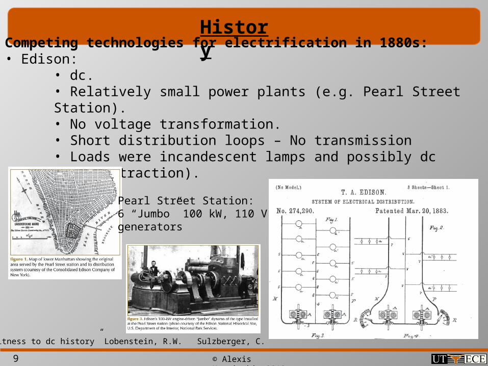
Competing technologies for electrification in 1880s: • Edison:
• dc.• Relatively small power plants (e.g. Pearl Street Station).• No voltage transformation.• Short distribution loops – No transmission• Loads were incandescent lamps and possibly dc motors (traction).
“Eyewitness to dc history” Lobenstein, R.W. Sulzberger, C.
Pearl Street Station:6 “Jumbo” 100 kW, 110 Vgenerators

10 © Alexis Kwasinski, 2013
History
Competing technologies for electrification in 1880s: •Tesla:
• ac• Large power plants (e.g. Niagara Falls)• Voltage transformation.• Transmission of electricity over long distances• Loads were incandescent lamps and induction motors.
http://spiff.rit.edu/classes/phys213/lectures/niagara/niagara.html
Niagara Falls historic power plant:38 x 65,000 kVA, 23 kV, 3-phase
generatods

11 © Alexis Kwasinski, 2013
History
Edison’s distribution system characteristics: 1880 – 2000 perspective
• Power can only be supplied to nearby loads (< 1mile).
• Many small power stations needed (distributed concept).
• Suitable for incandescent lamps and (dc) traction motors only.
• Cannot be transformed into other voltages (lack of flexibility).
• Higher cost than centralized ac system.
• Used inefficient and complicated coal – steam actuated generators (as oppose to hydroelectric power used by ac initial centralized systems).
• Not suitable for induction motor.
12 © Alexis Kwasinski, 2013
History
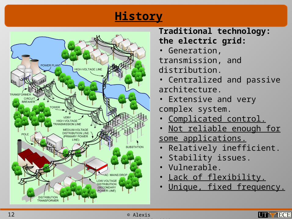
Traditional technology: the electric grid:• Generation, transmission, and distribution.• Centralized and passive architecture.• Extensive and very complex system.• Complicated control.• Not reliable enough for some applications.• Relatively inefficient.• Stability issues.• Vulnerable.• Lack of flexibility.• Unique, fixed frequency.
13 © Alexis Kwasinski, 2013
HistoryEdison’s distribution system characteristics: 2000 – future perspective • Power supplied to nearby loads is more efficient, reliable and secure than long power paths involving transmission lines and substations.
• Many small power stations needed (distributed concept).
• Existing grid not suitable for dc loads (e.g., computers) or to operate induction motors at different speeds. Power electronics allows varying speeds in induction motors and to feed dc loads.
• Power electronics allows for voltage and current signals to be transformed (flexibility).
• Transportation electrification needs.
• Can use renewable and alternative power sources.
• Can integrate energy storage.
• Power electronics is the one single technology that Edison needed in the late 1800s.

14 © Alexis Kwasinski, 2013
Power electronic applications
• Dynamic:• Variable speed drives in industries• Arguably for wind generation• Electric and hybrid electric cars (and other transportation applications)
• Stationary:• UPS• Energy storage integration • Information and communication technologies power plants• Power supplies• Solar power• Micro-grids• • •
15 © Alexis Kwasinski, 2013
Power electronics basics
• Types of interfaces:• dc-dc: dc-dc converter• ac-dc: rectifier• dc-ac: inverter• ac-ac: cycloconverter (used less often)
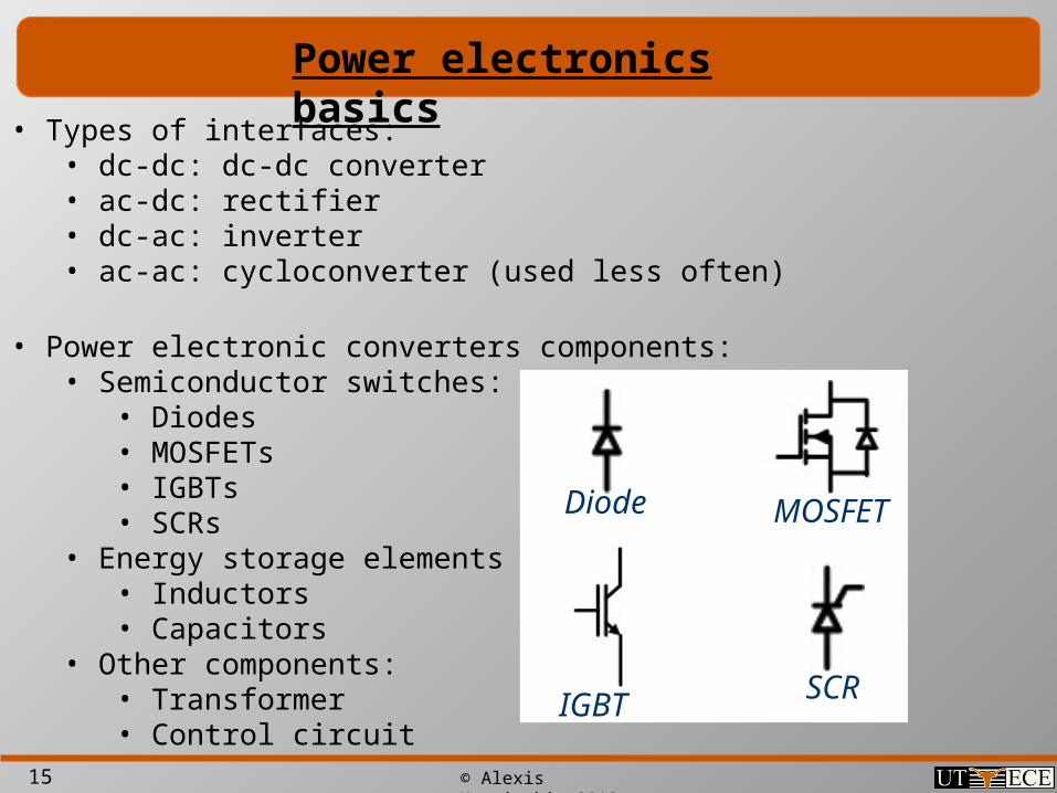
• Power electronic converters components:• Semiconductor switches:
• Diodes• MOSFETs• IGBTs• SCRs
• Energy storage elements • Inductors• Capacitors
• Other components:• Transformer• Control circuit
Diode MOSFET
IGBT SCR

16 © Alexis Kwasinski, 2013
Power electronics basics• dc-dc converters
oV DE
• Buck converter
1o
EV
D
• Boost converter
1o
DEV
D
• Buck-boost converter

17 © Alexis Kwasinski, 2013
Power electronics basics
• Rectifiers
Rectifier Filter
ttt
vv v
18 © Alexis Kwasinski, 2013
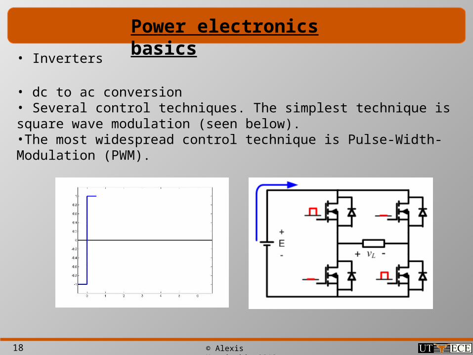
Power electronics basics
• Inverters
• dc to ac conversion• Several control techniques. The simplest technique is square wave modulation (seen below).•The most widespread control technique is Pulse-Width-Modulation (PWM).
19 © Alexis Kwasinski, 2013
Power electronics basic concepts
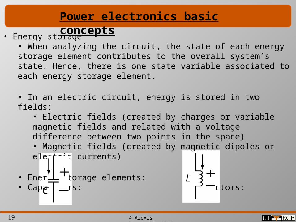
• Energy storage• When analyzing the circuit, the state of each energy storage element contributes to the overall system’s state. Hence, there is one state variable associated to each energy storage element.
• In an electric circuit, energy is stored in two fields:• Electric fields (created by charges or variable magnetic fields and related with a voltage difference between two points in the space)• Magnetic fields (created by magnetic dipoles or electric currents)
• Energy storage elements:• Capacitors: Inductors:
CL

20 © Alexis Kwasinski, 2013
Power electronics basic concepts
•Capacitors:• state variable: voltage• Fundamental circuit equation:
• The capacitance gives an indication of electric inertia. Compare the above equation with Newton’s
• Capacitors will tend to hold its voltage fixed. • For a finite current with an infinite capacitance, the voltage must be constant. Hence, capacitors tend to behave like voltage sources (the larger the capacitance, the closer they resemble a voltage source)• A capacitor’s energy is
CC
dvi C
dt
dvF m
dt
21
2CW Cv

21 © Alexis Kwasinski, 2013
Power electronics basic concepts• Inductors
• state variable: current• Fundamental circuit equation:
• The inductance gives an indication of electric inertia. Inductors will tend to hold its current fixed.• Any attempt to change the current in an inductor will be answered with an opposing voltage by the inductor. If the current tends to drop, the voltage generated will tend to act as an electromotive force. If the current tends to increase, the voltage across the inductor will drop, like a resistance.• For a finite voltage with an infinite inductance, the current must be constant. Hence, inductors tend to behave like current sources (the larger the inductance, the closer they resemble a current source)• An inductor’s energy is
LL
div L
dt
21
2LW Li

22 © Alexis Kwasinski, 2013
Power electronics basic concepts
• Since capacitors behave like constant voltage sources you shall never connect a switch in parallel with a capacitor. Any attempt to violate this load will lead to high currents. Likewise, you shall never connect a switch in series with an inductor. Any attempt to violate this rule will lead to high voltages.
•Steady state:• In between steady states there are transient periods,
• In steady state the energy in each of the energy storage elements is the same at the beginning and end of the cycle T. That is, ideally power input = power output
• Of course, during the transient periods (if they could be called “periods”) there is a difference between the initial and final energy.
• E.g. inductor: 21
2LW Li

23 © Alexis Kwasinski, 2013
• The average voltage across an inductor operating in periodic steady state is zero.
• Likewise, the average current through a capacitor operating in periodic steady state is zero.
• Hence, Both KCL and KVL apply in the average sense.
Power electronics basic concepts
21
2LW Li ( ) (0)i T i
0 0
1 1( ) ( ) ( ( ) (0))
T T
L L
Lv t v t dt Ldi i T i
T T T
( ) 0Lv t
( ) 0Ci t
( ) 0dW t 0P

24 © Alexis Kwasinski, 2013
• Time constants: In power electronics we tend to work in many circuits with “large” capacitances and inductances which leads to “large” time constants.
• What does “large” means? Large means time constants much larger than the period (whatever the period is. For example, a switching period.
• If you look close and for a short time interval, exponentials look like lines
Power electronics basic concepts
2for small t1 1
2t tt
e t e t
LL
R C RC
Time constant time scale Period time scale
25 © Alexis Kwasinski, 2013
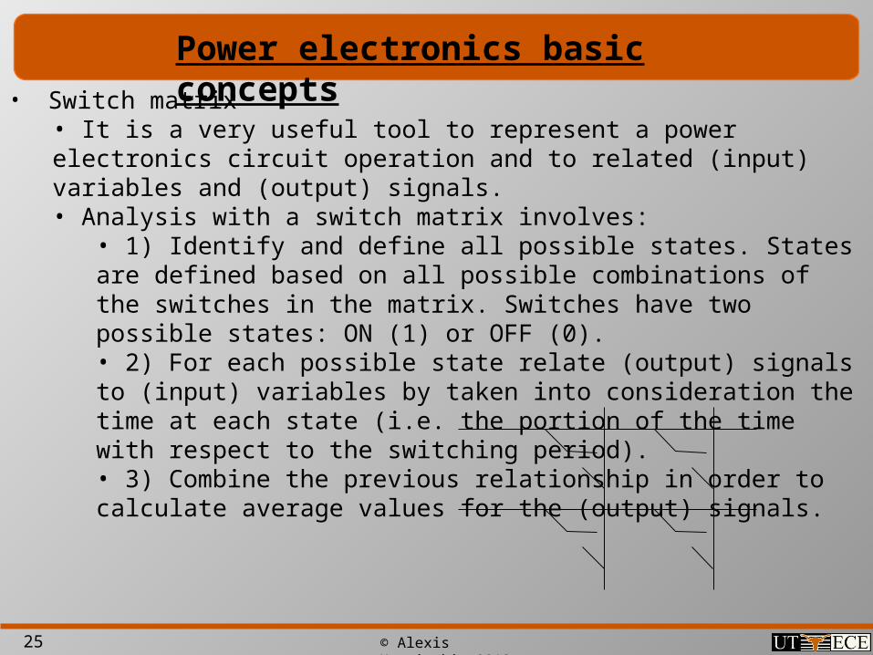
• Switch matrix• It is a very useful tool to represent a power electronics circuit operation and to related (input) variables and (output) signals.• Analysis with a switch matrix involves:
• 1) Identify and define all possible states. States are defined based on all possible combinations of the switches in the matrix. Switches have two possible states: ON (1) or OFF (0).• 2) For each possible state relate (output) signals to (input) variables by taken into consideration the time at each state (i.e. the portion of the time with respect to the switching period).• 3) Combine the previous relationship in order to calculate average values for the (output) signals.
Power electronics basic concepts

26 © Alexis Kwasinski, 2013
• Switch selection• There are two criteria:
• Current conduction direction• There are two possible directions:
• Forward – Usually from source to load• Bi directional – Both directions• (if current only circulates in the reverse direction, just reverse the switch and make it a forward conducting switch).
• Voltage present at the switch when it is blocking the current flow.• The definition relies on the voltage polarity off the switch when it is blocking current flow and with respect to the forward current direction convention.• Can be reverse blocking (RB - diode), forward blocking (FB – BJT or MOSFET), or bi-directional blocking (BB - GTO).
• Switches power rating is significantly higher than their losses.
Power electronics basic concepts
+ -

27 © Alexis Kwasinski, 2013
Power electronics basics
• Harmonics
• Concept: periodic functions can be represented by combining sinusoidal functions
• Underlying assumption: the system is linear (superposition principle is valid.)
• e.g. square-wave generation.
01
( ) cos( )n nn
f t c c n t

28 © Alexis Kwasinski, 2013
Power electronics basics
• Additional definitions related with Fourier analysis
01
( ) ( cos( ) sin( ))n nn
f t a a n t b n t
2( )cos( )
T
na f t n t dtT
1tan nn
n
b
a
0
1( )
Ta f t dt
T
2( )sin( )
T
nb f t n t dtT
2 2n n nc a b
0 0 (dc components)a c

29 © Alexis Kwasinski, 2013
• In power electronic circuits, signals usually have harmonics added to the desired (fundamental) signal.
• Energy storage elements are used to• Provide intermediate energy transfer buffers.• Filter undesired harmonics
• There are two approaches:• Linear approximation (based on time constants considerations). I.e., current and voltage ripples)
• Harmonic superposition
Power electronics basic concepts
CC
VI C
T
L
L
IV L
T

30 © Alexis Kwasinski, 2013
Power electronics basics
• Additional definitions
• Average
• RMS value
• Instantaneous power
• (Average) power
• Total harmonic distortion
2 2 2 2 20 0 , ,0
1 1 0
1 1( ) ( )
2
T
RMS n n RMS n RMSn n n
f t f t dt c c c c cT
( ) ( ) ( )p t v t i t
1( ) ( )
Tf t f t dt
T
0 01
1( ) ( ) cos( )
2
Tn n
Vn Inn
V IP v t i t dt V I
T
2
221
nn
cTHD
c
31 © Alexis Kwasinski, 2013
Power electronics basics
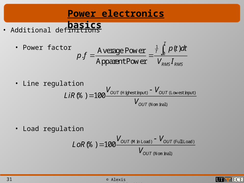
• Additional definitions
• Power factor
• Line regulation
• Load regulation
(Highest input ) (Lowest input )
(Nominal)
(%) 100 OUT OUT
OUT
V VLiR
V
(Min Load) (Full Load)
(Nominal)
(%) 100 OUT OUT
OUT
V VLoR
V
1
0( )Average Power
.Apparent Power
T
T
RMS RMS
p t dtp f
V I