*1 - dtic.mil · i comments on ferrite phaesitrcngrtosfrth m!l-tcu ... $in 0102-014-6601 _____...
TRANSCRIPT

7 AD-A119 913 NAVAL RESEARCH LAO WASHINGTON DC Fi ./6I COMMENTS ON FERRITE PHAESITRCNGRTOSFRTH M!L-TCU
ISEP 82 M4 L REUSS. AS SHFE COFGRTOSFRTEMLI TCU
UNCLASSIFIED NRL-MR-4921

*1

SECURITY CLASSIFICATION OF "mIS PAGE fRW7l Date E.,..d)
READ INSTRUCTIONSREPORT DOCUMENTATION PAGE BEFORE COUPLETING FORM
1 REPORT NUMBER 2. GOVT ACCESSION NO. 3. RECIPIENT'S CATALOG NUMBER'NRL Memorandum Report 4921 j-fo la e/ 34. TITLE[ (and41 $wb#J.*e) S. TYPE OF REPORT 6 OIIOO COVERED
COMMENTS ON FERRITE PHASE SHIFTER Interim report on a continuing
CONFIGURATIONS FOR THE MILLIMETER WAVE NRL problem.REGION 6. PERFORMING ORG. REPORT NUMBER
7. AUTNORr J 8. CONTRACT OR GRANT NUMBERtO)
M.L. Reuss, Jr.S. PERFORMING ORGANIZAION NAME AND AOORSS 10. PROGRAM ELEMENT. PROJECT. TASK
AREA & WORK UNIT NUMBERS
Naval Research LaboratoryWashington, DC 20375 68-0832-A-2
II. CONTROLLING OFFICE NAME AND AODRESS 12. REPORT DATE
Naval Electronic Systems Command September 28, 1982Washington, DC 20360 ,1 NUMBER OF PAGES
1314. MONITORING AGENCY NAME I AORESS(lI dillrent from Controllln Oflce) iS. SiCURITY CLASS. r.1 t .report)
UNCLASSIFIEDiea. DECLASSIFICATION/DOWNGRAOING
SCOEDULE
16. DISTRIBUTION STATEMENT (of this Report)
Approved for public release; distribution unlimited.
17. DISTRIBUTION STATEMENT 'ot the iabstrct eltered In Block 20. II dil.lerOt from Repor)
I0. SUPOPLEM4ENTARY NOTES
1. KEY WOROS (Continue on rvevrie ilde IIt nocoeoa md identlfy by block number)
Millimeter wave phase shifters
20. AIBSTRACT (Contiu an rveroe side It necessary aidenflly by block number)
>In the microwave region of the electromagnetic spectrum, electronically controllableferrite phase shifters have demonstrated their value as components and as control.elementa'for switches and attenuators. As the need for control components operating in the lowermillimeter wave region increases, it is a reasonable approach to scale successful microwaveferrite configurations Into the lower millimet:r wave region (30 GHz to 140 GHz).
(Continues)O 1 1473 EDITION Oi I NOV6 IS OBSOlETE
$IN 0102-014-6601 ______________________SCUIRITY CLASSIFICATION OF THIS PAGE (Whim Does later")
c-I:4

SCutSTy CL&SSIrICATIOk OF T.IS PAGI (Whooo De. E.1.10)
sO. ASSTRACT (Continued)
-However, many problems are encountered when attempting to scale efficient micro-wave ferrite configurations, particularly latching ferrite configurations, into themillimeter wave region. It is the objective of this report to review several ferrite con-figurations with the intent that consideration of these configurations may stimulatedevelopment of practical millimeter wave configurations. Ferrite phase shifter con-figurations that will be the subject of comment include the toroidal (dual slab),dual mode, Bush-Reggia-Spencer, and single slab configurations. Comments are alsopresented on a circulator used as a phase shifter..
.c ce :.,o Vo L...- l
l 5pi& ".3 -
|Copy/
20
SISCUOITY CLASSIFICATION OF THIS VAGr#t%0n Data SOeen)
iiI
COMMENTS ON FERRITE PHASE SHIFTER CONFIGURATIONSFOR THE MILLLIMETER WAVE REGION
In the microwave region of the electromagnetic spectrum, electronicallycontrollable ferrite phase shifters have demonstrated their value as com-ponents and as control elements for switches and attenuators. As the need forcontrol components operating in the lower millimeter wave region increases, itis a reasonable approach to scale successful microwave ferrite configurationsinto the lower millimeter wave region (30 GHz to 140 GHz). However, manyproblems are encountered when attempting to scale efficient microwaveferrite configurations, particularly latching ferrite configurations, intothe millimeter wave region. It is the objective of this report to reviewseveral ferrite configurations with the intent that consideration of theseconfigurations may stimulate development of practical millimeter wave con-figurations.
One of the first problems encountered in scaling microwave ferrite con-figurations into the millimeter wave region is that of material limitations;to values on the order of 5000 gauss. While saturation magnetizations lessthan 5,000 gauss are adequate in the microwave region, this 5000 gaussmagnetization limitation is partially responsible for reduced performance ofmillimeter wave, as compared to microwave, phase shifters. The impact of thepresent 5000 gauss magnetization limit will be illustrated during thediscussion of the twin slab/toroidal ferrite phase shifter.
Several of the following ferrite phase shifter configurations will bethe subject of comments. The toroidal and dual mode phase shifters which havedemonstrated their value as latching (no holding current required) phase-shifters in the microwave region. Both types can produce relatively fre-quency independent phase shift values over broad (over an octave) orreasonable (10 to 15%) bandwidths respectively. The Bush-Reggia-Spencerphase shifter, a configuration having frequency dependent phase shift, hasbeen employed in the microwave region; while latching versions of this con-figuration have been built, employment of these rectangular waveguide con-figurations has been limited. Other configurations built or considered forthe microwave region include latching circulators employed as phase shiftersand single ferrite slab phase shifters in rectangular waveguide,. These andother possible ferrite configurations are covered in limited depth in thefollowing paragraphs.
Twin Slab (Toroidal) Ferrite Phase Shifter: This rectangular waveguidephase shifter, in two basic configurations, has advanced the state-of-the-artin the microwave region by virtue of its fast switching speed, differentialphase shift essentially independent of frequency, high power capability,latching implementations and reasonable loss. Its nonreciprocalcharacteristics are of advantage in certain applications (e.g., switchablecirculators). Due to its success in the microwave region, units have beenbuilt in the lower portion of the millimeter wave region and are available
- Manusaipt submitted July 27, 1982.1

commercially in the 30 to 40 GHz region; however, problems regardingfabrication and performance have been evident in the higher mid-millimeterwave region.
Since there are many articles(1)( 2) in the open literature describing thedesign and operation of these units, no attempt will be made to repeat thisinformation. A typical, though not optimized, X-band design (10 GHz)capable of operating over a 20Z bandwidth will be scaled and calculationsmade to illustrate various problems currently encountered. Modeling of thetoroidal phase shifter is based on the twin slab ferrite configuration ofFigure 1(a). Figure 1(b) and 1(c) illustrate practical implementations ofthe basic model. The single toroid version of Figure 1(b) will be used forillustrative purposes even though the somewhat greater loss version of Figure1(c) has advantages in the millimeter wave region since the drive wires forthe toroids are in a lower electric field region and less likely to introducemoding, assuming that higher order modes can propagate.
Calculations of phase shift and electrical length were performed using acomputer program based on the analysis of Clark.( 3) In arriving at thedesign for the X-band configuration, the differential phase shift was to beessentially frequency-independent (less than 1% variation) over a MO% band-width, and, for case 1, only the dominant mode was to propagate, while, forcase 2, the LSE 11 and/or LSM11 modes would be capable of propagating. Inpractice, the LSE11 and LSM 11, if excited, could be suppressed by using an ab-sorptive film orthogonal to the electric field as shown in Figure 2. Theprincipal difference between case 1 and case 2 is the height of the aveguidewith case 1 having the smaller value of waveguide dimension "b". Figure 3illustrates the impact of height reduction on insertion loss of WR-28rectanguilar waveguide. By analogy it is evident that reduction of thewaveguide height for the ferrite-loaded configuration will also have anadverse effect on the insertion loss.
Table I indicates the dimensions of the X-band (10 GHz) toroidal phaseshifter and scaled models designed to operate at 35, 60 and 95 GHz. Practical
fabricability of the 60 GHz and particularly the 95 GHz units pose problems inregard to obtaining uniform dielectric-loaded ferrite toroids with space for adrive wire; it is difficult to place a reasonable diameter wire through the0.221 to 0.140 n toroid hole. Mechanical tolerances also become much morecritical.
Table II indicates electrical characteristics of the priiucipal X-banddesign and the scaled designs. Note that the scaled (desired) values ofsaturation magnetization are not available; thus 5000 gauss material wasemployed for the higher frequency designs. While the differential phaseshift (&*) in the millimeter wave region is relatively constant, the averageelectrical length (Bay) of the phase shifter increases at the higherfrequencies as indicated by the ratio of 60/8av. In practice, loss increaseswhen &O/Bav increases.
Matching the toroidal phase shifter to the standard transmission line isusually achieved by use of quarter-wave dielectric sections. The number ofquarter-wave sections increases as the bandwidth requirement increases; three(3) to four (4) sections are required for full rectangular waveguide bandoperation. Scaling of multistep transformer dimensions into the millimeterregion could prove as much or more of a fabrication challenge than fabricationof dielectrics for center loading of toroids.
2i * ,.

Dual Mode Phase Shifter: The dual mode phase shifter, a reciprocal phaseshifter, consists of a nonreciprocal Faraday Rotator with a nonreciprocalcircular polarizer at each end of the rotator. Hatching transformers fromrectangular to circular waveguide are also provided. Switching speeds arerestricted by the shorted turns effect introduced by the waveguide housing.Latching circuits are provided for the Faraday Rotation Section. Figure 4 in-dicates a typical dual mode phase shifter configuration. Laboratory unitsof this type have been built to operate up to 60 GHz.( 4) A major problem in-volved in design of these units at 95 GHz is concerned with implementation ofthe nonreciprocal polarizers. Bandwidths on the order of 15% have beenachieved at microwave frequencies. Due to the field distribution within thisunit, the conduction loss contributions toward total insertion loss is lessthan that of the toroidal phase shifter.
Bush-Reggia-Spencer Phase Shifter: This reciprocal ferrite phase shifterconfigurationk)' O) has been successfully implemented at frequencies in boththe microweave and millimeter wave regions. Units with 2% bandwidth areavailable commercially up to 110 GHz. A holding current is required for themillimeter wave units constructed. Again, due to the shorted turns effect,switching speeds are restricted. Phase shift produced by this configurationvaries as a function of frequency and the bandwidth is restricted. Whilelatching versions of this phase shifter has been built at microwavefrequencies (7), these units have had limited application.
Figure 5 illustrates several implementations of this phase shifter con-figuration and phase shift obtained from three (3) of the configurations( 8);cross-sectional views of the original configiration (Fig.5(a)), a modificationof the original configuration (Fig.5(b)), a complementary configuration tothat of Fig.5(b), (Fig.5(c)), a full height slab configuration (Fig.5(d)), anda modified full height configuration (Fig.5(e)). The configuration ofFig.5(a) has been successfully implemented into the millimeter wave region;bandwidths on the order of 2%. It is evident that there are no efficientpaths -onfigurations of Fig.5(a) or 5(b) to conduct heat from the ferriteto the waveguide thus an average power limitation is incurred. Use of aferrite slab, Fig.5(d), provides a heat link for the ferrite but is lessefficient than the configuration of Fig.5(b). Fig.5(e) depicts a modificationof the configuration of Fig.5(b) which increases the efficiency. Goodferrite-to-metal contact is essential to prevent generation of unwanted modes.The last configuration (Fig.5(e) and Fig.6) depict a configuration that mayoffer potential for the millimeter wave region. Inspection of Fig.5(f)indicates the phase shift characteristics of configurations 5(b) through 5(e)at X-band. Faster switching speed may be possible by slitting the waveguideto reduce the shorter turns effect( 9)(I0) while addition of yokes would allowlatching operation over a portion of the millimeter wave region and/or allowoperation with a holding field.

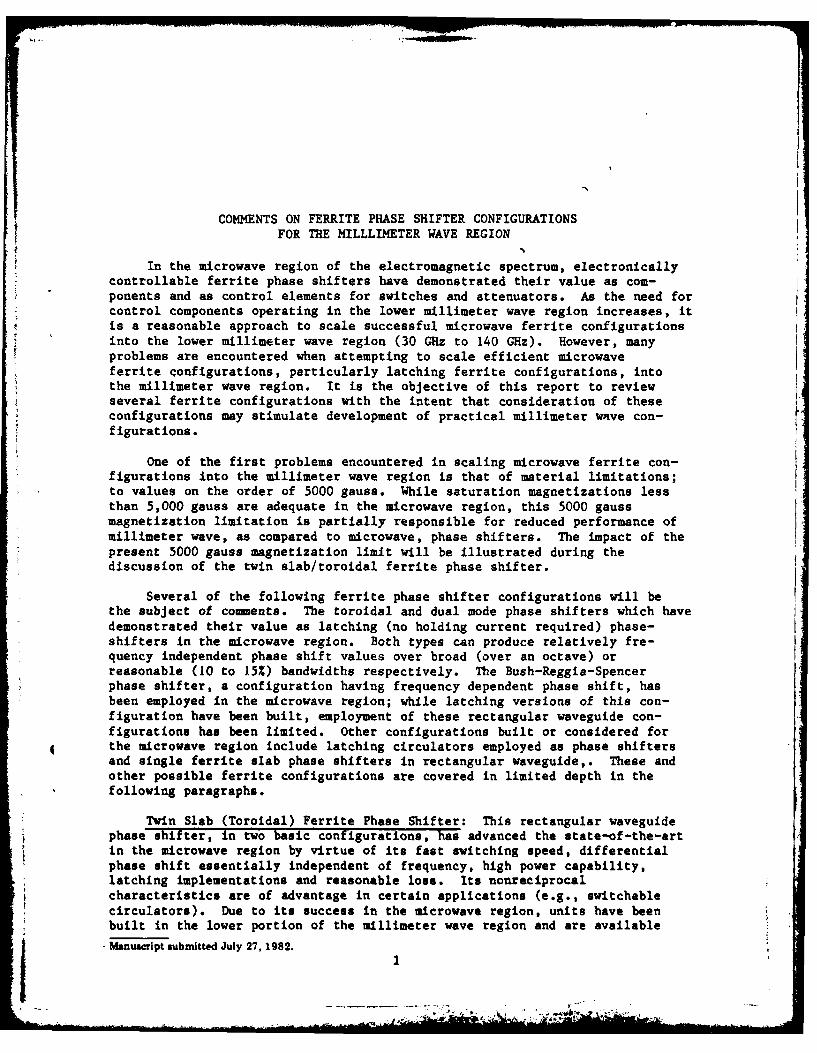
Latching Circulator Phase Shifter: A phase shifter configuration thatmay be of limited use in the lower millimeter region is shown in Fig. 8. Thisreflection-type configuration consists of a junction circulator with two portsterminated. The magnetization applied to the three-port junction circulatoris varied, either via use of an electrocagaet or use of a latching circulator,thus diverting different amounts of energy into each of the two (2) shortedarms. Maximum phase shift would be obtained when the magnetization isapproximately that required for circulator action. This configuration, whichwas initially implemented in shielded triplate in the lower microwave region,*is considered of limited applicability due to the limitations imposed on thecirculator by saturization and remenent magnetization limitations. Fig. 7 in-dicates X-band measurements with this configuration; a circulator designed foruse with permanent magnets was employed with an electromagnet replacing theoriginal permanent magnets. The magnitude of the phase shift is, in part,dependent on the length of the shorted line sections.
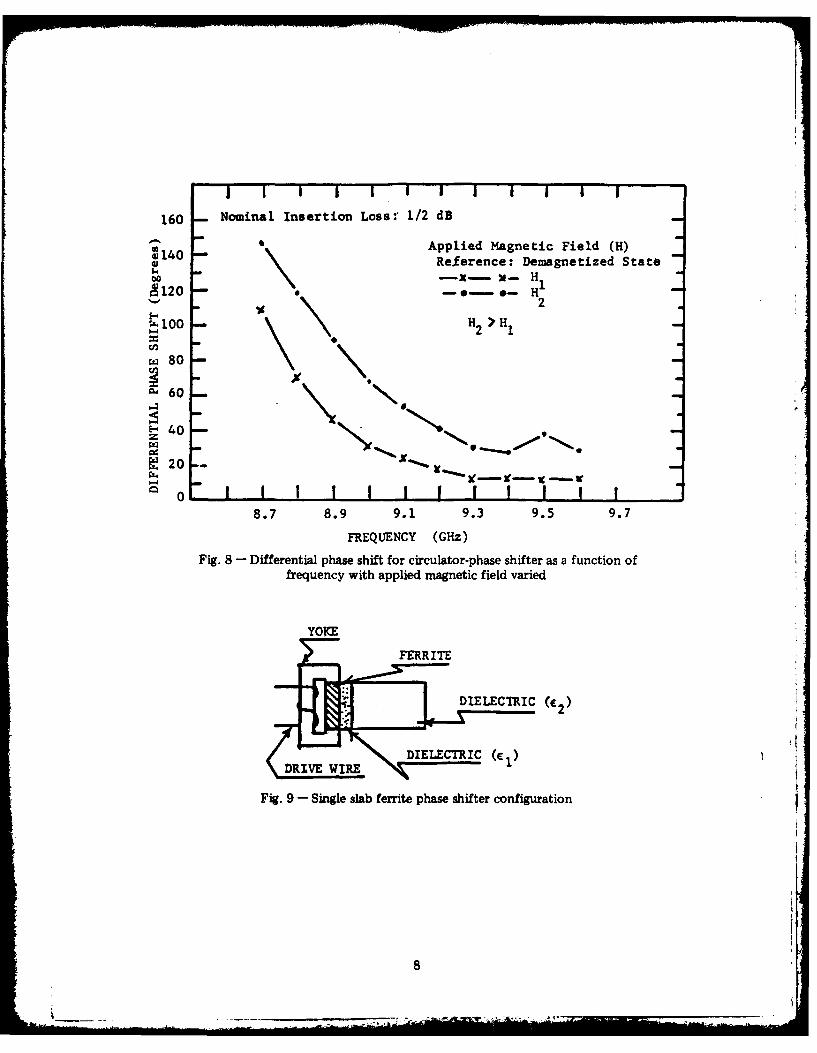
Single Slab Ferrite Phase Shifter: Use of a single ferrite slab withtransverse applied field can also produce nonreciprocal phase shift. Whilethis configuration may not be as efficient as a dual slab configuration,implementation at millimeter wave frequencies may be easier. A toroid inwaveguide is not required (only ferrite and dielectric slabs are required) andthe drive wire is part of the external circuit as is the case with dual modephase shifter configurations. Moding potential is thus reduced ar theexpense of remenent magnetic field.
Figure 9 indicates the configuration with two (2) dielectric materials(FI and E2) one of which may be air. Figure 10 indicates measured phase shiftfor one combination of ferrite and dielectric. Calculated differential phaseshift for this configuration was from 3610 at 9.6 GHz to 3440 at 12 GHz.Based on analyses, a broadband configuration is feasible. An adhesive couldbe used to form a ferrite-dielectric loaded waveguide which could bemetalized. Additional efforts are anticipated in regard to adapting thisconfiguration to the millimeter wave region.
Fin Line Phase Shifter: A fin line isolator has been built(ll); thisintroduced the possibility of developing a fin line latching phase shifter.?igure 11 indicates the fin line isolator. A ready extrapolation of theisolator design to a latching phase shifter design is indicated in Figs.l1(a)and 11(b). Since, in practice, a waveguide-type housing is present about thefin line so that only one (1) mode would propagate, this configuration wouldreduce to a configuration which would be similar to that of a waveguide withan internally located ferrite toroid. Similar problems with regard to higherorder modes, toroid size and tolerances would be present. It was thus decidedthat additional in-house efforts on this configuration would have a lowpriority.
In summary, several ferrite phase shifter configurations have beenconsidered for use at millimeter wave frequencies. No practicalimplementations of latching configurations are currently available in the mid-(90 to 140 GHz) millimeter wave region. The most efficient microwave latchingconfigurations are under investigation by commercial organizations.Bush-Reggia-Spencer phase shifters requiring holding magnetic fields areavailable through 110 GHz, Additional configurations are under investigation.
Unit was developed by Hughes Aircraft Company under Navy contract.
4
* , - . "

F\%~ FER R ITE DIELECTRIC
(a) (b) (c)
Fig. 1 -Twin slab, "toroid," phase shifter configurations
FERRITE TOROI
ABSORBING MATERIALDIELETRIC(MODE SUPPRESSOR)
Fig. 2 - Ferrite toroid with thin film absorbing material in place
0.025 I I I I I
0.7
0,020 00001 .6
0.5
0.015 4
0 0.4b-0.254 cm
(0.100"1)
0.010 0in.356 cm 0.3( 0.14 0"
0.2
0.005 I I I I I I26 28 30 32 34 36 38 40
FREQUENCY (GHz)Fig. 3 - Waveguide low for three values of waveguide heighit (b)
5

Fig. 4 -Dual mode phase shifter
(a) (b) (C)
WET
800FRQ:9.5 GHz(b
700 -(e)
600 (d)500
400-40
D 300
200
[,..
X 100
0-
10o 200 300 400APPLIED MAGNETIC FIELD
-100 - (0.)-100 C)
-200 -(f)
Fig. 5 - Differential phase-shift dependence on applied magnetic firlefor four waveguide configurations. In all cases the ferrite-slab width is0.250 inch and the applied magnetic field is along the waveguide axes.
6

Fig. 6 - Suggested millimeter wave ferrite phase shifter configuration
(LATCHING CIRCUIT)
SHORT CIXCUI SHORT CIRCUITEDWAVEGUIDE* AEU~
WR 90*WAVEGUIDE
Fig. 7 - Circulator - phase shifter
7
I I I I I -I I I I I i e
160 Nominal Insertion Loss:' 1/2 dB
Applied Magnetic Field (H)45140 0 Reference: Demagnetized State
0 -x- 3t- H18120 o-- - H-
2100 H >H
2 1
80
~60 N
40
00 o- ! I I l l I ! !I"
8.7 8.9 9.1 9.3 9.5 9.7
FREQUENCY (Gz)
Fig. 8 - Differential phase shift for circulator-phase shifter as a function offrequency with applied magnetic field varied
YOKE
FERRITE
DIELECTRIC
Fig. 9 - Single slab ferrite phase shifter configuration
8

H: Applied Magnetic Field
:400 - He H? H21H,00360 -.- -
Z320 -4
5" 280
S240 - --..... * * - H3
6: 200
2E- 1.20z
~L40
9 10 Li 12FREQUENCY (GHz)
Fig. 10 - Differential phase shift of a single slab phase shifter as afunction of frequency and applied magnetic field
APPLIED) MAGNETIC
T LD FIN
DIELECTRIC ASRE
FERRITE
Fig. 11 - Fin line isolator
/-EILLNE FNLN
FERRITEFERRIT DIELECTRIC TOROIDS
TOROIIDL CT I
(a) (b)
Fig. 12 - Fin line latching phase shifters
9

TABLE I
(All dimensions in m unless otherwise indicated)
Center a bDesign I a bj T w s b2Freq.
12.446 4.445 4.365 1.524 1.321 8.89010 GHz 0.490") (0.175") (0.172") (0.060") (0.052") (0.350"
3.556 1.270 1.245 0.432 0.381 2.54035 GHz (0.140") (0.050") (0.049") (0.017") (0.015") (0.100")
I 2.075 0. 0.729 0.254 0.2211 1.48160 Hz (0.0516") (0.0291") (0.0287") (0.010") (0.0087") (0.0583")
1.311 0.467 0.424 ' 0.460 0.140 0.93595 GHz (0.0516") (0.0184") (0.0181") (0.0063") (0.0055") (0.0368")
TABLE II
(A; Differential Phase Shift; -Electrical Length)
Center Design! iDesired jUtilized 0 Cutoff frequency (GHz)Frequency lb(mm) 4l1N 41Ms /cmiA /Bav LSE I LSM11 I LSE20
4.445 2000 2000 366 0.171 11.4 13.4 11.010 GHz 8.8901 2000 I 2000 366 0.171 7.0 9.8 11.0
1 1270 "00"892 0 0118 40.1 146.9 773.6135 GHz 2.5401 7000 5000 854 0.115 24.6 34.3 38.7
60M Wz 144 5.6 88 8.636 0.481 12000 5000 847 0.066 42.1 8 6 66
S0.467i 19000 500"0 880 0.042 108.8 1127.1 1 W4.76195 GHz 0.935119000 5000 843 0.041 64.9 91.0 104.8
10

Acknowledgment
The author expresses his appreciation to Mr.Crawford Banks, who ablyassisted in taking the experimental data.
References
1. Schloman, E., "Theoretical Anslysis of Twin Slab Phase Shifters inRectangular Waveguide," T-MTT Vol.14, #1, Jan. 1966, pp.15-23.
2. Whicker, L.R., and Bolle, D.M., "Annotated Literature Survey ofMicrowave Ferrite Control Components and Materials for 1968-1974,"T-MTT Vol.23, #11, Nov.1975, pp.908-918.
3. Clark, W.P., Hering, K.H., and Charlton, D.A., "TE-mode Solutions forPartially Ferrite-Filled Rectangular Waveguide Using ABCD Matrices,"IEEE Internatl.Convention Record, Vol.14, Part 5, Mar.1966, pp.39-48.
4. Boyd, C.R., Jr., "A 60 GHz Dual-Mode Ferrite Phase Shifter," IEEEMTT-S Internatl. Microwave Sympos.Digest, Jun. 1982, pp. 2 5 7-25 9 .
5. Bush, D., "Discussion on Microwave Apparatus," Proc.Inst.Elect.Engr.(London), Vol.104B, Suppl.6, 1957, p.368.
6. Reggia, F., and Spencer, E.G., "A New Technique in Ferrite PhaseShifting for Beam Scanning of Mictowave Antennas," Proc.I.R.E. 45,1957, pp.1510-1517.
7. Bardash, I.,, and Maune, J.J., "A Waveguide Reciprocal Latching FerritePhase Shifter," 1968 G-MTI Symposium Digest.
8. Reuss, M.L., Jr., "Phase Shift Enhancement by Mode-Suppression Tech-niques," NRL Report #6677, Apr. 1968.
9. Reggia, F., and Hatcher, R.D., "Properties of Ferrites and Their Appli-cations to Microwave Systems," Diamond Ordnance Fuze LaboratoriesReport #TR-6784, Feb. 1959.
10. Reuss, M.L., Jr., "Ferrite-Loaded Open Transmission Line," NRL Report#5867, Feb. 1963.
11. Beyer, A., and Solbach, K.J., "Fin Line Ferrite Isolator for IntegratedMillimeter Wave Circuits," 1981 IEEE MTT-S Internatl.Symposium Digest,
pp.296-298.
11

I