1 - engine and peripherals
DESCRIPTION
Manual de Oficina Renault Megane IIITRANSCRIPT
© Renault s.a.s 2008
"The repair methods given by the manufacturer in this document are based on the technicalspecifications current when it was prepared.
The methods may be modified as a result of changes introduced by the manufacturer in theproduction of the various component units and accessories from which his vehicles areconstructed."
All copyrights reserved by Renault.
The reproduction or translation in part of whole of the present document, as well as the useof the spare parts reference numbering system, are prohibited without the prior writtenconsent of Renault.
JUNE 2008 Edition Anglaise
X95, and F4R or F9Q or K4M or K9K
1 Engine and peripherals
10A ENGINE AND CYLINDER BLOCK ASSEMBLY
11A TOP AND FRONT OF ENGINE
12A FUEL MIXTURE
12B TURBOCHARGING
13A FUEL SUPPLY
13B DIESEL INJECTION
13C PREHEATING
14A ANTIPOLLUTION
16A STARTING - CHARGING
17A IGNITION
17B PETROL INJECTION

© Renault s.a.s 2008
"The repair methods given by the manufacturer in this document are based on the technicalspecifications current when it was prepared.
The methods may be modified as a result of changes introduced by the manufacturer in theproduction of the various component units and accessories from which his vehicles areconstructed."
All copyrights reserved by Renault.
The reproduction or translation in part of whole of the present document, as well as the useof the spare parts reference numbering system, are prohibited without the prior writtenconsent of Renault.
JUNE 2008 Edition Anglaise
X95, and F4R or F9Q or K4M or K9K
19A COOLING
19B EXHAUST
19C TANK
19D ENGINE MOUNTING

MEGANE III - Section 1
Contents
Page
MEGANE III - Section 1ContentsPage
10AENGINE AND CYLINDER BLOCK ASSEMBLY
Crankshaft seal at timing end Removal - Refitting 10A-1
Crankshaft seal at gearbox end : Removal - Refitting 10A-12
Sump: Removal - Refitting 10A-25
Engine oil: Draining - Refilling 10A-40
Oil filter: Removal - Refitting 10A-48
Exchanger: Removal - Refitting 10A-55
Oil pressure sensor: Removal - Refitting 10A-64
Oil level sensor: Removal - Refitting 10A-69
Oil pump: Removal - Refitting 10A-76
Oil pressure: Check 10A-82
Multifunction support: Removal - Refitting 10A-84
Engine/gearbox assembly: Removal - Refitting 10A-98
Flywheel: Removal - Refitting 10A-157
11A TOP AND FRONT OF ENGINE
Final compression pressure: Check 11A-1
Accessories belt: Removal - Refitting 11A-7
Crankshaft accessories pulley: Removal - Refitting 11A-15
Timing belt: Removal - Refitting 11A-29
Rocker cover: Removal - Refitting 11A-88
Camshaft: Removal - Refitting 11A-114
Cylinder head: Removal - Refitting 11A-135
Camshaft dephaser: Removal - Refitting 11A-177
Camshaft dephaser solenoid valve: Removal - Refitting 11A-184
Camshaft seal at timing end: Removal - Refitting 11A-186
Oil decanter: Removal - Refitting 11A-205
12A FUEL MIXTURE
Air resonator: Removal - Refitting 12A-1
Air filter: Removal - Refitting 12A-2
Air filter unit: Removal - Refitting 12A-4
Air flowmeter: Removal - Refitting 12A-7
Air inlet flap: Removal - Refitting 12A-11
Throttle valve: Removal - Refitting 12A-17
Throttle valve: Cleaning 12A-21
11A TOP AND FRONT OF ENGINE

Contents
Inlet manifold: Removal - Refitting 12A-23
Injector holder shim: Removal - Refitting 12A-31
Exhaust manifold - Intake distributor: Removal - Refitting 12A-34
Exhaust manifold: Removal - Refitting 12A-37
12B TURBOCHARGING
Turbocharging: Precautions for repair 12B-1
Turbocharger: Removal - Refitting 12B-8
Turbocharger oil pipe: Removal - Refitting 12B-22
Intercooler: Removal - Refitting 12B-37
Intercooler air inlet pipe: Removal - Refitting 12B-41
Turbocharger outlet exhaust gas duct: Removal - Refitting 12B-49
Intercooler air outlet pipe: Removal - Refitting 12B-56
13A FUEL SUPPLY
Manual priming pump: Removal - Refitting 13A-1
Fuel filter : Removal - Refitting 13A-3
Fuel pressure: check 13A-7
Fuel flow: check 13A-10
12A FUEL MIXTURE 13B DIESEL INJECTION
Diesel injection: Precautions for repair 13B-1
Diesel injection: List and location of components 13B-12
Diesel injection computer: Removal - Refitting 13B-17
Camshaft position sensor: Removal - Refitting 13B-19
Crankshaft position sensor: Removal - Refitting 13B-25
Leak flow from high-pressure pump: Check 13B-27
High pressure pump: Removal - Refitting 13B-30
Fuel flow actuator: Removal - Refitting 13B-54
Venturi: Removal - Refitting 13B-58
Diesel return pipe: Removal - Refitting 13B-62
Diesel injector fuel return rail: Removal - Refitting 13B-63
Injector rail protector: Removal - Refitting 13B-70
High-pressure pipe between the pump and rail: Removal - Refitting 13B-71
High-pressure pipe between the rail and injector: Removal - Refitting 13B-87
Injector rail: Removal - Refitting 13B-108
Rail pressure sensor: Removal - Refitting 13B-117
Fuel temperature sensor: Removal - Refitting 13B-118
Leak flow from injectors: Check 13B-126

Contents
Diesel injector: Removal - Refitting 13B-136
Accelerometer: Removal - Refitting 13B-150
13C PREHEATING
Pre/postheating unit: Removal - Refitting 13C-1
Heater plugs Removal - Refitting 13C-3
14A ANTIPOLLUTION
Fuel vapour canister: Removal - Refitting 14A-1
Exhaust gas recirculation solenoid valve: Removal - Refitting 14A-3
Intercooler: Removal - Refitting 14A-7
Exhaust gas recirculation assembly: Removal - Refitting 14A-18
Exhaust gas recirculation rigid pipe: Removal - Refitting 14A-30
16A STARTING - CHARGING
Alternator: Removal - Refitting 16A-1
Starter: Removal - Refitting 16A-16
13B DIESEL INJECTION 17A IGNITION
Coils Removal - Refitting 17A-1
Spark plugs: Removal - Refitting 17A-5
17B PETROL INJECTION
Oxygen sensors: Removal - Refitting 17B-1
Petrol injection computer: Removal - Refitting 17B-7
Pinking sensor: Removal - Refitting 17B-9
Camshaft position sensor: Removal - Refitting 17B-13
Crankshaft position sensor: Removal - Refitting 17B-15
Injector rail - Injectors: Removal - Refitting 17B-19
19A COOLING
Engine cooling circuit: Specifications 19A-1
Engine cooling circuit: check 19A-2
Engine cooling circuit: List and location of components 19A-4
Cooling circuit: Draining - Refilling 19A-17
Cooling radiator: Removal - Refitting 19A-31
Water pump: Removal - Refitting 19A-45
Thermostat: Removal - Refitting 19A-57
Plenum chamber: Removal - Refitting 19A-61
Engine cooling fan assembly: Removal - Refitting 19A-73

Contents
Water pump inlet pipe: Removal - Refitting 19A-83
Expansion bottle: Removal - Refitting 19A-96
Electric water pump: Removal - Refitting 19A-99
Coolant temperature sensor: Removal - Refitting 19A-101
19B EXHAUST
Exhaust: Parts and consumables for the repair work 19B-1
Exhaust: Precautions for repair 19B-12
Catalytic converter: Removal - Refitting 19B-17
Expansion chamber: Removal - Refitting 19B-31
Connector pipe: Removal - Refitting 19B-35
Silencer: Removal - Refitting 19B-40
Particle filter: Removal - Refitting 19B-47
Exhaust gas temperature sensor: Removal - Refitting 19B-50
Particle filter pressure sensor: Removal - Refitting 19B-52
Particle filter temperature sensors: Removal - Refitting 19B-53
Exhaust fuel injector: Removal - Refitting 19B-54
Exhaust fuel injector solenoid valve: Removal - Refitting 19B-56
Exhaust fuel injector cooler: Removal - Refitting 19B-58
Connecting hose: Removal - Refitting 19B-60
19A COOLING 19C TANK
Fuel tank: Draining 19C-1
Fuel tank: Removal - Refitting 19C-4
Filler neck: Removal - Refitting 19C-14
Fuel level sensor module: Removal - Refitting 19C-16
19D ENGINE MOUNTING
Left-hand suspended engine mounting: Removal - Refitting 19D-1
Right-hand suspended engine mounting: Removal - Refitting 19D-18
Lower engine tie-bar: Removal - Refitting 19D-33

10A-1
ENGINE AND CYLINDER BLOCK ASSEMBLYCrankshaft seal at timing end Removal - Refitting
K4M
10A
REMOVAL
I - REMOVAL PREPARATION OPERATION
a Position the vehicle on a two-post lift (see Vehicle:Towing and lifting) (02A, Lifting equipment).
a Disconnect the battery (see Battery: Removal - Re-fitting) (80A, Battery).
a Remove:
- the engine cover,
- the throttle valve (see 12A, Fuel mixture, Throttlevalve: Removal - Refitting, page 12A-17) ,
- the windscreen wiper arms (see Windscreen wi-per arm: Removal - Refitting) (85A, Wiping -Washing),
- the scuttle panel grille (see Scuttle panel grille:Removal - Refitting) (56A, Exterior equipment),
- the scoop under the scuttle panel grille (see Scoopunder scuttle panel grille: Removal - Refitting)(56A, Exterior equipment),
- the front right-hand wheel (see Wheel: Removal -Refitting) (35A, Wheels and tyres),
- the front section of the front right-hand wheel archliner (see Front wheel arch liner: Removal - Re-fitting) (55A, Exterior protection),
- the engine undertray bolts,
- the engine undertray,
- the lower engine tie-bar (see 19D, Engine moun-ting, Lower engine tie-bar: Removal - Refitting,page 19D-33) ,
- the accessories belt (see 11A, Top and front ofengine, Accessories belt: Removal - Refitting,page 11A-7) ,
- the crankshaft accessories pulley (see 11A, Topand front of engine, Crankshaft accessoriespulley: Removal - Refitting, page 11A-15) ,
- the right-hand suspended engine mounting (see19D, Engine mounting, Right-hand suspendedengine mounting: Removal - Refitting, page19D-18) ,
- the timing belt (see 11A, Top and front of engine,Timing belt: Removal - Refitting, page 11A-29) ,
- the crankshaft timing sprocket.
II - OPERATION FOR REMOVAL OF PART CONCERNED
a Remove the crankshaft seal (1) at the timing end.
REFITTING
I - REFITTING PREPARATION OPERATION
a parts always to be replaced: Crankshaft seal ontiming end (10,03,03,04).
a Use SURFACE CLEANER (see Vehicle: Parts and ingredients for the repairwork) (04B, Consu-mables - Products) to clean and degrease:
- the seal mating face on the crankshaft,
- the seal housing on the cylinder block.
Essential special tooling
Mot. 1385 Crankshaft oil seal fitting tool(timing end) (35 x 47 x 7)
134680
WARNING
To ensure proper sealing, the gasket surfacesmust be clean, dry and not greasy (avoid any fin-ger marks).

10A-2
ENGINE AND CYLINDER BLOCK ASSEMBLYCrankshaft seal at timing end Removal - Refitting
K4M
10AII - REFITTING OPERATION FOR PART CONCERNED
a Refit a new crankshaft seal at the timing end, usingthe tool (Mot. 1385) (2) .
III - FINAL OPERATION
a Refit:
- the crankshaft timing sprocket,
- the timing belt (see 11A, Top and front of engine,Timing belt: Removal - Refitting, page 11A-29) ,
- the right-hand suspended engine mounting (see19D, Engine mounting, Right-hand suspendedengine mounting: Removal - Refitting, page19D-18) ,
- the crankshaft accessories pulley (see 11A, Topand front of engine, Crankshaft accessoriespulley: Removal - Refitting, page 11A-15) ,
- the accessories belt (see 11A, Top and front ofengine, Accessories belt: Removal - Refitting,page 11A-7) ,
- the lower engine tie-bar (see 19D, Engine moun-ting, Lower engine tie-bar: Removal - Refitting,page 19D-33) ,
- the engine undertray,
- the front section of the front right-hand wheel archliner (see Front wheel arch liner: Removal - Re-fitting) (55A, Exterior protection),
- the front right-hand wheel (see Wheel: Removal -Refitting) (35A, Wheels and tyres),
- the scoop under the scuttle panel grille (see Scoopunder scuttle panel grille: Removal - Refitting)(56A, Exterior equipment),
- the scuttle panel grille (see Scuttle panel grille:Removal - Refitting) (56A, Exterior equipment),
- the windscreen wiper arms (see Windscreen wi-per arm: Removal - Refitting) (85A, Wiping -Washing),
- the throttle valve (see 12A, Fuel mixture, Throttlevalve: Removal - Refitting, page 12A-17) ,
- the engine cover.
a Connect the battery (see Battery: Removal - Refit-ting) (80A, Battery).
134681

10A-3
ENGINE AND CYLINDER BLOCK ASSEMBLYCrankshaft seal at timing end Removal - Refitting
K9K
10A
REMOVAL
I - REMOVAL PREPARATION OPERATION
a Position the vehicle on a two-post lift (see Vehicle:Towing and lifting) (02A, Lifting equipment).
a Disconnect the battery (see Battery : Removal -Refitting) (80A, Battery).
a Remove:
- the engine cover,
- the front right-hand wheel (see Wheel: Removal -Refitting) (35A, Wheels and tyres),
- the front section of the front right-hand wheel archliner (see Front wheel arch liner: Removal - Re-fitting) (55A, Exterior protection),
- the engine undertray bolts,
- the engine undertray,
- the accessories belt (see 11A, Top and front ofengine, Accessories belt: Removal - Refitting,page 11A-7) ,
- the crankshaft accessories pulley (see 11A, Topand front of engine, Crankshaft accessoriespulley: Removal - Refitting, page 11A-15) .
a Remove the lower engine tie-bar (see 19D, Enginemounting, Lower engine tie-bar: Removal - Refit-ting, page 19D-33) .
a Remove:
- the windscreen wiper arms (see Windscreen wi-per arm: Removal - Refitting) (85A, Wiping -Washing),
- the scuttle panel grille (see Scuttle panel grille:Removal - Refitting) (56A, Exterior equipment),
- the scoop under the scuttle panel grille (see Scoopunder scuttle panel grille: Removal - Refitting)(56A, Exterior equipment),
- the right-hand suspended engine mounting (see19D, Engine mounting, Right-hand suspendedengine mounting: Removal - Refitting, page19D-18) .
a Remove the camshaft position sensor (see 13B,Diesel injection, Camshaft position sensor: Re-moval - Refitting, page 13B-19) .
a Remove the timing belt (see 11A, Top and front ofengine, Timing belt: Removal - Refitting, page11A-29) .
a Remove the crankshaft timing sprocket (1) .
Essential special tooling
Mot. 1577 Lip seal extractor (shaft dia-meter 28 mm to 42 mm).
Mot. 1586 Tool for fitting PTFE cranks-haft seal, timing end.
Mot. 1714 Adapter for fitting PTFEcrankshaft seal, timing end.
K9K, and 830
K9K, and 830
109043
10A-4
ENGINE AND CYLINDER BLOCK ASSEMBLYCrankshaft seal at timing end Removal - Refitting
K9K
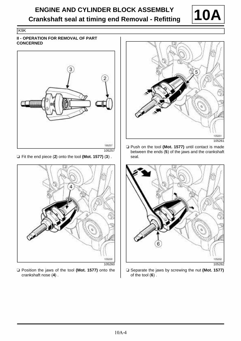
10AII - OPERATION FOR REMOVAL OF PART CONCERNED
a Fit the end piece (2) onto the tool (Mot. 1577) (3) .
a Position the jaws of the tool (Mot. 1577) onto thecrankshaft nose (4) .
a Push on the tool (Mot. 1577) until contact is madebetween the ends (5) of the jaws and the crankshaftseal.
a Separate the jaws by screwing the nut (Mot. 1577)of the tool (6) .
105257
105260
105261
105262

10A-5
ENGINE AND CYLINDER BLOCK ASSEMBLYCrankshaft seal at timing end Removal - Refitting
K9K
10A
a Screw down the threaded rod (7) of the (Mot. 1577).
a Remove the crankshaft seal using the tool (Mot.1577).
REFITTING
I - REFITTING PREPARATION OPERATION
a
a Use SURFACE CLEANER (see Vehicle: Parts and ingredients for the repairwork) (04B, Consu-mables - Products) to clean and degrease:
- the crankshaft seal mating face on the crankshaft,
- the crankshaft seal housing in the crankshaft closu-re panel.
a parts always to be replaced: Crankshaft seal ontiming end (10,03,03,04).
II - REFITTING OPERATION FOR PART CONCERNED
a Tighten the threaded rod (8) :
- of the tool (Mot. 1586) in the crankshaft with anM12 thread,
- of the tool (Mot. 1714) in the crankshaft with anM14 thread.
a Insert the spacer (9) of the (Mot. 1586) in thecrankshaft.
105263
WARNING
To ensure proper sealing, the gasket surfacesmust be clean, dry and not greasy (avoid any fin-ger marks).
20772
20771

10A-6
ENGINE AND CYLINDER BLOCK ASSEMBLYCrankshaft seal at timing end Removal - Refitting
K9K
10A
a Fit the protector equipped with the crankshaft sealonto the spacer, taking care not to touch the cranks-haft seal.
a Fit the cover (10) and the nut (11) (positioning thethread (12) of the nut towards the outside of the en-gine).
a Screw on the nut until the cover touches the spacer.
20770
20769
20768
20767

10A-7
ENGINE AND CYLINDER BLOCK ASSEMBLYCrankshaft seal at timing end Removal - Refitting
K9K
10A
a Remove:
- the nut,
- the cover,
- the protector,
- the spacer,
- the threaded rod.
III - FINAL OPERATION
a Refit:
- the crankshaft timing sprocket,
- the timing belt (see 11A, Top and front of engine,Timing belt: Removal - Refitting, page 11A-29) .
a Refit the camshaft position sensor (see 13B, Dieselinjection, Camshaft position sensor: Removal -Refitting, page 13B-19) .
a Refit:
- the right-hand suspended engine mounting (see19D, Engine mounting, Right-hand suspendedengine mounting: Removal - Refitting, page19D-18) ,
- the scoop under the scuttle panel grille (see Scoopunder scuttle panel grille: Removal - Refitting)(56A, Exterior equipment),
- the scuttle panel grille (see Scuttle panel grille:Removal - Refitting) (56A, Exterior equipment),
- the windscreen wiper arms (see Windscreen wi-per arm: Removal - Refitting) (85A, Wiping -Washing),
a Refit the lower engine tie-bar (see 19D, Enginemounting, Lower engine tie-bar: Removal - Refit-ting, page 19D-33) .
a Refit:
- the crankshaft accessories pulley (see 11A, Topand front of engine, Crankshaft accessoriespulley: Removal - Refitting, page 11A-15) ,
- the accessories belt (see 11A, Top and front ofengine, Accessories belt: Removal - Refitting,page 11A-7) ,
- the engine undertray,
- the front section of the front right-hand wheel archliner (see Front wheel arch liner: Removal - Re-fitting) (55A, Exterior protection),
- the front right-hand wheel (see Wheel: Removal -Refitting) (35A, Wheels and tyres),
- the engine cover.
a Connect the battery (see Battery : Removal - Refit-ting) (80A, Battery).
20766
K9K, and 830
K9K, and 830
10A-8
ENGINE AND CYLINDER BLOCK ASSEMBLYCrankshaft seal at timing end Removal - Refitting
F4R
10A
REMOVAL
I - REMOVAL PREPARATION OPERATION
a Position the vehicle on a two-post lift (see Vehicle:Towing and lifting) (02A, Lifting equipment).
a Remove:
- the engine cover,
- the battery (see Battery: Removal - Refitting)(80A, Battery),
- the battery tray (see Battery tray: Removal - Re-fitting) (80A, Battery),
- the engine undertray bolts,
- the engine undertray,
- the front wheels (see Wheel: Removal - Refitting)(35A, Wheels and tyres),
- the front section of the front wheel arch liners (seeFront wheel arch liner: Removal - Refitting)(55A, Exterior protection),
- the front bumper (see Front bumper: Removal -Refitting) (55A, Exterior protection),
- the radiator mounting cross member (see Radiatorsupport cross member: Removal - Refitting)(31A, Front axle components),
- the accessories belt (see 11A, Top and front ofengine, Accessories belt: Removal - Refitting,page 11A-7) ,
- the crankshaft accessories pulley (see 11A, Topand front of engine, Crankshaft accessoriespulley: Removal - Refitting, page 11A-15) ,
- the lower engine tie-bar (see 19D, Engine moun-ting, Lower engine tie-bar: Removal - Refitting,page 19D-33) ,
- the windscreen wiper arms (see Windscreen wi-per arm: Removal - Refitting) (85A, Wiping -Washing),
- the scuttle panel grille (see Scuttle panel grille:Removal - Refitting) (56A, Exterior equipment),
- the scoop under the scuttle panel grille (see Scoopunder scuttle panel grille: Removal - Refitting)(56A, Exterior equipment),
- the right-hand suspended engine mounting (see19D, Engine mounting, Right-hand suspendedengine mounting: Removal - Refitting, page19D-18) ,
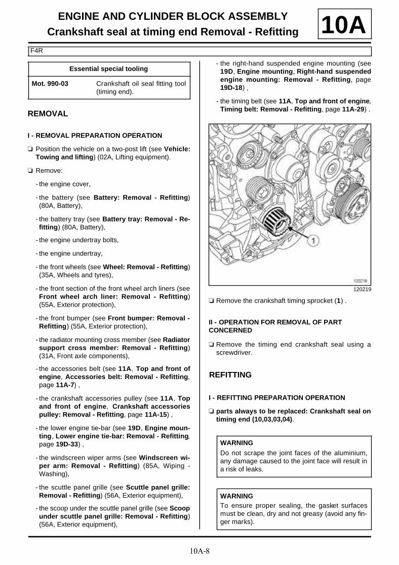
- the timing belt (see 11A, Top and front of engine,Timing belt: Removal - Refitting, page 11A-29) .
a Remove the crankshaft timing sprocket (1) .
II - OPERATION FOR REMOVAL OF PART CONCERNED
a Remove the timing end crankshaft seal using ascrewdriver.
REFITTING
I - REFITTING PREPARATION OPERATION
a parts always to be replaced: Crankshaft seal ontiming end (10,03,03,04).
Essential special tooling
Mot. 990-03 Crankshaft oil seal fitting tool(timing end).
120219
WARNING
Do not scrape the joint faces of the aluminium,any damage caused to the joint face will result ina risk of leaks.
WARNINGTo ensure proper sealing, the gasket surfacesmust be clean, dry and not greasy (avoid any fin-ger marks).

10A-9
ENGINE AND CYLINDER BLOCK ASSEMBLYCrankshaft seal at timing end Removal - Refitting
F4R
10Aa Use SURFACE CLEANER (see Vehicle: Parts
and ingredients for the repairwork) (04B, Consu-mables - Products) to clean and degrease:
- the crankshaft seal mating face,
- the cylinder block seal housing.
II - REFITTING OPERATION FOR PART CONCERNED
a Refit a new crankshaft seal at the timing end, usingthe tool (Mot. 990-03) (2) .
III - FINAL OPERATION
a Refit:
- the crankshaft timing sprocket,
- the timing belt (see 11A, Top and front of engine,Timing belt: Removal - Refitting, page 11A-29) ,
- the right-hand suspended engine mounting (see19D, Engine mounting, Right-hand suspendedengine mounting: Removal - Refitting, page19D-18) ,
- the scoop under the scuttle panel grille (see Scoopunder scuttle panel grille: Removal - Refitting)(56A, Exterior equipment),
- the scuttle panel grille (see Scuttle panel grille:Removal - Refitting) (56A, Exterior equipment),
- the windscreen wiper arms (see Windscreen wi-per arm: Removal - Refitting) (85A, Wiping -Washing),
- the lower engine tie-bar (see 19D, Engine moun-ting, Lower engine tie-bar: Removal - Refitting,page 19D-33) ,
- the crankshaft accessories pulley (see 11A, Topand front of engine, Crankshaft accessoriespulley: Removal - Refitting, page 11A-15) ,
- the accessories belt (see 11A, Top and front ofengine, Accessories belt: Removal - Refitting,page 11A-7) ,
- the radiator mounting cross member (see Radiatorsupport cross member: Removal - Refitting)(31A, Front axle components),
- the front bumper (see Front bumper: Removal -Refitting) (55A, Exterior protection),
- the front section of the front wheel arch liners (seeFront wheel arch liner: Removal - Refitting)(55A, Exterior protection),
- the front wheels (see Wheel: Removal - Refitting)(35A, Wheels and tyres),
- the engine undertray,
- the battery tray (see Battery tray: Removal - Re-fitting) (80A, Battery),
- the battery (see Battery: Removal - Refitting)(80A, Battery),
- the engine cover.
120220

10A-10
ENGINE AND CYLINDER BLOCK ASSEMBLYCrankshaft seal at timing end Removal - Refitting
F9Q
10A
REMOVAL
I - REMOVAL PREPARATION OPERATION
a Position the vehicle on a two-post lift (see Vehicle:Towing and lifting) (02A, Lifting equipment).
a Disconnect the battery (see Battery : Removal -Refitting) (80A, Battery).
a Remove:
- the engine cover,
- the engine undertray bolts,
- the engine undertray,
- the front right-hand wheel (see Wheel: Removal -Refitting) (35A, Wheels and tyres),
- the front right-hand wheel arch liner (see Frontwheel arch liner: Removal - Refitting) (55A, Ex-terior protection),
- the accessories belt (see 11A, Top and front ofengine, Accessories belt: Removal - Refitting,page 11A-7) ,
- the crankshaft accessories pulley (see 11A, Topand front of engine, Crankshaft accessoriespulley: Removal - Refitting, page 11A-15) ,
- the lower engine tie-bar (see 19D, Engine moun-ting, Lower engine tie-bar: Removal - Refitting,page 19D-33) ,
- the windscreen wiper arms (see Windscreen wi-per arm: Removal - Refitting) (85A, Wiping -Washing),
- the scuttle panel grille (see Scuttle panel grille:Removal - Refitting) (56A, Exterior equipment),
- the scoop under the scuttle panel grille (see Scoopunder scuttle panel grille: Removal - Refitting)(56A, Exterior equipment),
- the right-hand suspended engine mounting (see19D, Engine mounting, Right-hand suspendedengine mounting: Removal - Refitting, page19D-18) ,
- the timing belt (see 11A, Top and front of engine,Timing belt: Removal - Refitting, page 11A-29) .
II - OPERATION FOR REMOVAL OF PART CONCERNED
a Remove:
- the crankshaft sprocket (1) ,
- the crankshaft seal at the timing end using a flat-blade screwdriver, taking care not to damage themating face of the crankshaft.
REFITTING
I - REFITTING PREPARATION OPERATION
a parts always to be replaced: Crankshaft seal ontiming end (10,03,03,04).
a Use SURFACE CLEANER (see Vehicle: Parts and ingredients for the repairwork) (04B, Consu-mables - Products) to clean and degrease:
- the crankshaft seal mating face on the crankshaft,
- the crankshaft seal housing on the cylinder block.
Essential special tooling
Mot. 990-03 Crankshaft oil seal fitting tool(timing end).
120219
WARNING
To ensure proper sealing, the gasket surfacesmust be clean, dry and not greasy (avoid any fin-ger marks).
10A-11
ENGINE AND CYLINDER BLOCK ASSEMBLYCrankshaft seal at timing end Removal - Refitting
F9Q
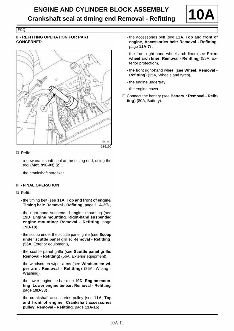
10AII - REFITTING OPERATION FOR PART CONCERNED
a Refit:
- a new crankshaft seal at the timing end, using thetool (Mot. 990-03) (2) ,
- the crankshaft sprocket.
III - FINAL OPERATION
a Refit:
- the timing belt (see 11A, Top and front of engine,Timing belt: Removal - Refitting, page 11A-29) ,
- the right-hand suspended engine mounting (see19D, Engine mounting, Right-hand suspendedengine mounting: Removal - Refitting, page19D-18) ,
- the scoop under the scuttle panel grille (see Scoopunder scuttle panel grille: Removal - Refitting)(56A, Exterior equipment),
- the scuttle panel grille (see Scuttle panel grille:Removal - Refitting) (56A, Exterior equipment),
- the windscreen wiper arms (see Windscreen wi-per arm: Removal - Refitting) (85A, Wiping -Washing),
- the lower engine tie-bar (see 19D, Engine moun-ting, Lower engine tie-bar: Removal - Refitting,page 19D-33) ,
- the crankshaft accessories pulley (see 11A, Topand front of engine, Crankshaft accessoriespulley: Removal - Refitting, page 11A-15) ,
- the accessories belt (see 11A, Top and front ofengine, Accessories belt: Removal - Refitting,page 11A-7) ,
- the front right-hand wheel arch liner (see Frontwheel arch liner: Removal - Refitting) (55A, Ex-terior protection),
- the front right-hand wheel (see Wheel: Removal -Refitting) (35A, Wheels and tyres),
- the engine undertray,
- the engine cover.
a Connect the battery (see Battery : Removal - Refit-ting) (80A, Battery).
136199

10A-12
ENGINE AND CYLINDER BLOCK ASSEMBLYCrankshaft seal at gearbox end : Removal - Refitting
K4M
10A
REMOVAL
I - REFITTING PREPARATION OPERATION
a Position the vehicle on a two-post lift (see Vehicle:Towing and lifting) (02A, Lifting equipment).
a Remove:
- the engine cover,
- the windscreen wiper arms (see Windscreen wi-per arm: Removal - Refitting) (85A, Wiping -Washing),
- the scuttle panel grille (see Scuttle panel grille:Removal - Refitting) (56A, Exterior equipment),
- the scoop under the scuttle panel grille (see Scoopunder scuttle panel grille: Removal - Refitting)(56A, Exterior equipment),
- the battery (see Battery: Removal - Refitting)(80A, Battery),
- the battery tray (see Battery tray: Removal - Re-fitting) (80A, Battery),
- the air filter unit (see 12A, Fuel mixture, Air filterunit: Removal - Refitting, page 12A-4) .
a Undo the clip on the throttle valve air inlet pipe.
a Disconnect the air filter unit air outlet pipe from thethrottle valve.
a Remove:
- the air outlet pipe from the air filter unit,
- the front wheels (see Wheel: Removal - Refitting)(35A, Wheels and tyres),
- the front section of the front wheel arch liners (seeFront wheel arch liner: Removal - Refitting)(55A, Exterior protection),
- the engine undertray bolts,
- the engine undertray,
- the front bumper (see Front bumper: Removal -Refitting) (55A, Exterior protection).
a Drain the manual gearbox (see Manual gearboxoil: Draining - Refilling) (21A, Manual gearbox).
a Remove:
- the starter (see 16A, Starting - Charging, Starter:Removal - Refitting, page 16A-16) ,
- the crankshaft position sensor (see 17B, Petrol in-jection, Crankshaft position sensor: Removal -
Refitting, page 17B-15) ,
- the lower engine tie-bar (see 19D, Engine moun-ting, Lower engine tie-bar: Removal - Refitting,page 19D-33) ,
- the front right-hand wheel driveshaft (see Front ri-ght-hand wheel driveshaft: Removal - Refitting)(29A, Driveshafts),
- the front left-hand wheel driveshaft (see Front left-hand wheel driveshaft: Removal - Refitting)(29A, Driveshafts),
- the differential output seals (see Differential out-put seal: Removal - Refitting) (21A, Manual gear-box),
- the radiator mounting cross member (see Radiatorsupport cross member: Removal - Refitting)(31A, Front axle components),
- the front axle subframe (see Front axle sub-fra-me: Removal - Refitting) (31A, Front axle compo-nents),
- the left-hand suspended engine mounting (see19D, Engine mounting, Left-hand suspendedengine mounting: Removal - Refitting, page19D-1) ,
- the manual gearbox (see Manual gearbox: Remo-val - Refitting) (21A, Manual gearbox).
- the « pressure plate - disc » assembly (see Me-chanism / Disk: Removal - Refitting) (20A,Clutch),
- the flywheel (see 10A, Engine and cylinder blockassembly, Flywheel: Removal - Refitting, page10A-157) .
Essential special tooling
Mot. 1129-01 Crankshaft oil seal fitting tool(flywheel end) (80 x 100 x 8seal).
Tightening torquesm
clip on the throttle valveair inlet pipe
6 N.m
10A-13
ENGINE AND CYLINDER BLOCK ASSEMBLYCrankshaft seal at gearbox end : Removal - Refitting
K4M
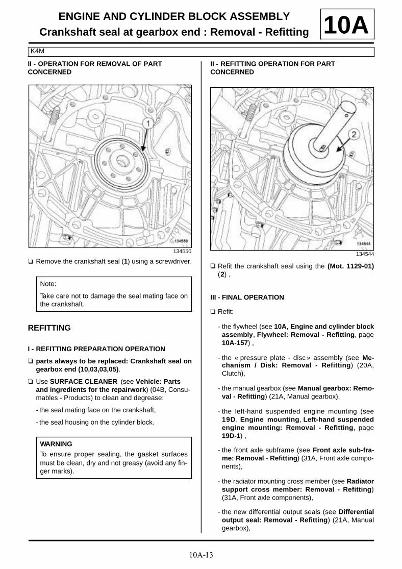
10AII - OPERATION FOR REMOVAL OF PART CONCERNED
a Remove the crankshaft seal (1) using a screwdriver.
REFITTING
I - REFITTING PREPARATION OPERATION
a parts always to be replaced: Crankshaft seal ongearbox end (10,03,03,05).
a Use SURFACE CLEANER (see Vehicle: Parts and ingredients for the repairwork) (04B, Consu-mables - Products) to clean and degrease:
- the seal mating face on the crankshaft,
- the seal housing on the cylinder block.
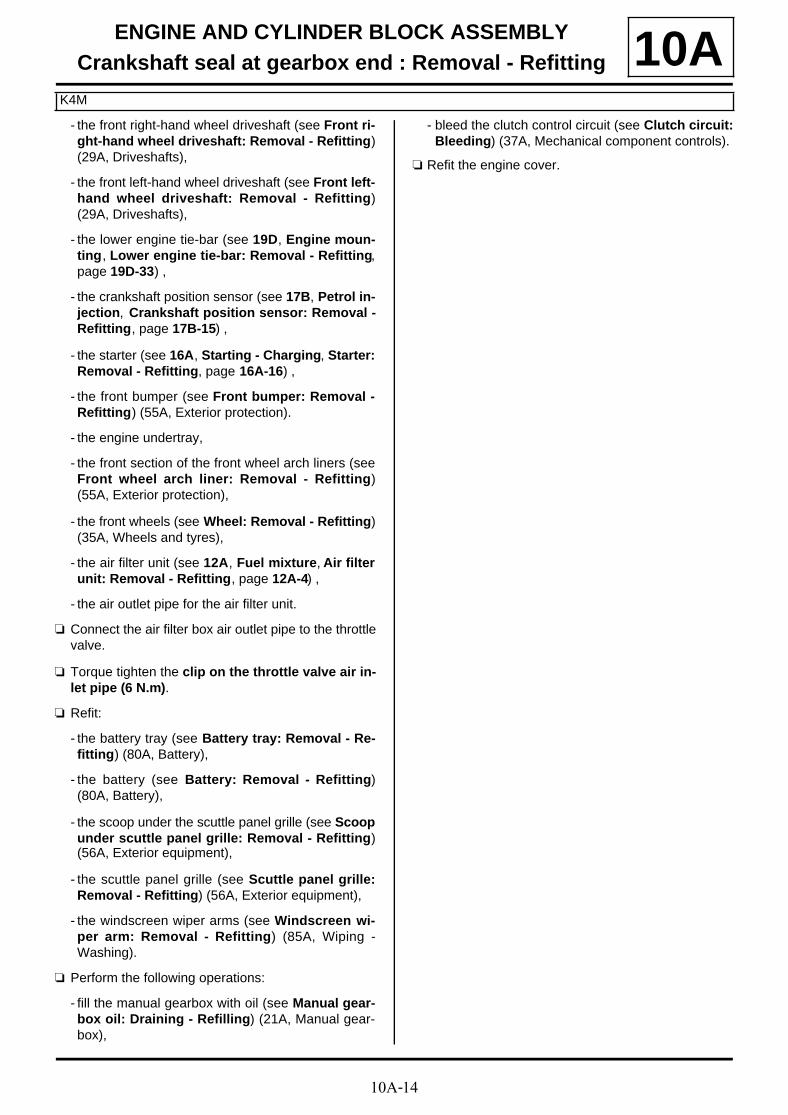
II - REFITTING OPERATION FOR PART CONCERNED
a Refit the crankshaft seal using the (Mot. 1129-01)(2) .
III - FINAL OPERATION
a Refit:
- the flywheel (see 10A, Engine and cylinder blockassembly, Flywheel: Removal - Refitting, page10A-157) ,
- the « pressure plate - disc » assembly (see Me-chanism / Disk: Removal - Refitting) (20A,Clutch),
- the manual gearbox (see Manual gearbox: Remo-val - Refitting) (21A, Manual gearbox),
- the left-hand suspended engine mounting (see19D, Engine mounting, Left-hand suspendedengine mounting: Removal - Refitting, page19D-1) ,
- the front axle subframe (see Front axle sub-fra-me: Removal - Refitting) (31A, Front axle compo-nents),
- the radiator mounting cross member (see Radiatorsupport cross member: Removal - Refitting)(31A, Front axle components),
- the new differential output seals (see Differentialoutput seal: Removal - Refitting) (21A, Manualgearbox),
134550
Note:
Take care not to damage the seal mating face onthe crankshaft.
WARNING
To ensure proper sealing, the gasket surfacesmust be clean, dry and not greasy (avoid any fin-ger marks).
134544
10A-14
ENGINE AND CYLINDER BLOCK ASSEMBLYCrankshaft seal at gearbox end : Removal - Refitting
K4M
10A- the front right-hand wheel driveshaft (see Front ri-ght-hand wheel driveshaft: Removal - Refitting)(29A, Driveshafts),
- the front left-hand wheel driveshaft (see Front left-hand wheel driveshaft: Removal - Refitting)(29A, Driveshafts),
- the lower engine tie-bar (see 19D, Engine moun-ting, Lower engine tie-bar: Removal - Refitting,page 19D-33) ,
- the crankshaft position sensor (see 17B, Petrol in-jection, Crankshaft position sensor: Removal -Refitting, page 17B-15) ,
- the starter (see 16A, Starting - Charging, Starter:Removal - Refitting, page 16A-16) ,
- the front bumper (see Front bumper: Removal -Refitting) (55A, Exterior protection).
- the engine undertray,
- the front section of the front wheel arch liners (seeFront wheel arch liner: Removal - Refitting)(55A, Exterior protection),
- the front wheels (see Wheel: Removal - Refitting)(35A, Wheels and tyres),
- the air filter unit (see 12A, Fuel mixture, Air filterunit: Removal - Refitting, page 12A-4) ,
- the air outlet pipe for the air filter unit.
a Connect the air filter box air outlet pipe to the throttlevalve.
a Torque tighten the clip on the throttle valve air in-let pipe (6 N.m).
a Refit:
- the battery tray (see Battery tray: Removal - Re-fitting) (80A, Battery),
- the battery (see Battery: Removal - Refitting)(80A, Battery),
- the scoop under the scuttle panel grille (see Scoopunder scuttle panel grille: Removal - Refitting)(56A, Exterior equipment),
- the scuttle panel grille (see Scuttle panel grille:Removal - Refitting) (56A, Exterior equipment),
- the windscreen wiper arms (see Windscreen wi-per arm: Removal - Refitting) (85A, Wiping -Washing).
a Perform the following operations:
- fill the manual gearbox with oil (see Manual gear-box oil: Draining - Refilling) (21A, Manual gear-box),
- bleed the clutch control circuit (see Clutch circuit:Bleeding) (37A, Mechanical component controls).
a Refit the engine cover.
10A-15
ENGINE AND CYLINDER BLOCK ASSEMBLYCrankshaft seal at gearbox end : Removal - Refitting
K9K
10A
REMOVAL
I - REMOVAL PREPARATION OPERATION
a Position the vehicle on a two-post lift (see Vehicle:Towing and lifting) (02A, Lifting equipment).
a Remove:
- the engine cover,
- the battery (see Battery : Removal - Refitting)(80A, Battery),
- the battery tray (see Battery tray: Removal - Re-fitting) (80A, Battery),
- the air filter unit (see 12A, Fuel mixture, Air filterunit: Removal - Refitting, page 12A-4) ,
- the engine undertray bolts,
- the engine undertray,
- the crankshaft position sensor (see 13B, Diesel in-jection, Crankshaft position sensor: Removal -Refitting, page 13B-25) ,
- the starter (see 16A, Starting - Charging, Starter:Removal - Refitting, page 16A-16) ,
- the front wheels (see Wheel: Removal - Refitting)(35A, Wheels and tyres),
- the front section of the front wheel arch liners (seeFront wheel arch liner: Removal - Refitting)(55A, Exterior protection).
a Drain the gearbox (see Manual gearbox oil: Drai-ning - Refilling) .
a Remove:
- the front left-hand wheel driveshaft (see Front left-hand wheel driveshaft: Removal - Refitting)(29A, Driveshaft),
- the front right-hand wheel driveshaft (see Front ri-ght-hand wheel driveshaft: Removal - Refitting)(29A, Driveshaft),
- the differential output seals (see Differential out-put seal: Removal - Refitting) (21A, Manual gear-box).
a Remove the lower engine tie-bar (see 19D, Enginemounting, Lower engine tie-bar: Removal - Refit-ting, page 19D-33) .
a Remove:
- the front bumper (see Front bumper: Removal -Refitting) (55A, Exterior protection),
- the radiator mounting cross member (see Radiatorsupport cross member: Removal - Refitting)(31A, Front axle components),
- the front axle subframe (see Front axle sub-fra-me: Removal - Refitting) (31A, Front axle compo-nents),
- the windscreen wiper arms (see Windscreen wi-per arm: Removal - Refitting) (85A, Wiping -Washing),
- the scuttle panel grille (see Scuttle panel grille:Removal - Refitting) (56A, Exterior equipment),
- the scoop under the scuttle panel grille (see Scoopunder scuttle panel grille: Removal - Refitting)(56A, Exterior equipment),
- the left-hand suspended engine mounting (see19D, Engine mounting, Left-hand suspendedengine mounting: Removal - Refitting, page19D-1) ,
- the manual gearbox (see Manual gearbox: Remo-val - Refitting) (21A, Manual gearbox).
- the hydraulic clutch release bearing (see Clutchthrust bearing: Removal - Refitting) (20A,Clutch),
- the clutch disc and pressure plate (see Mecha-nism / Disk: Removal - Refitting) (20A, Clutch),
- the flywheel (see 10A, Engine and cylinder blockassembly, Flywheel: Removal - Refitting, page10A-157) .
Essential special tooling
Mot. 1579 Lip seal extractor (shaft dia-meter 80 mm to 98 mm).
JR5

10A-16
ENGINE AND CYLINDER BLOCK ASSEMBLYCrankshaft seal at gearbox end : Removal - Refitting
K9K
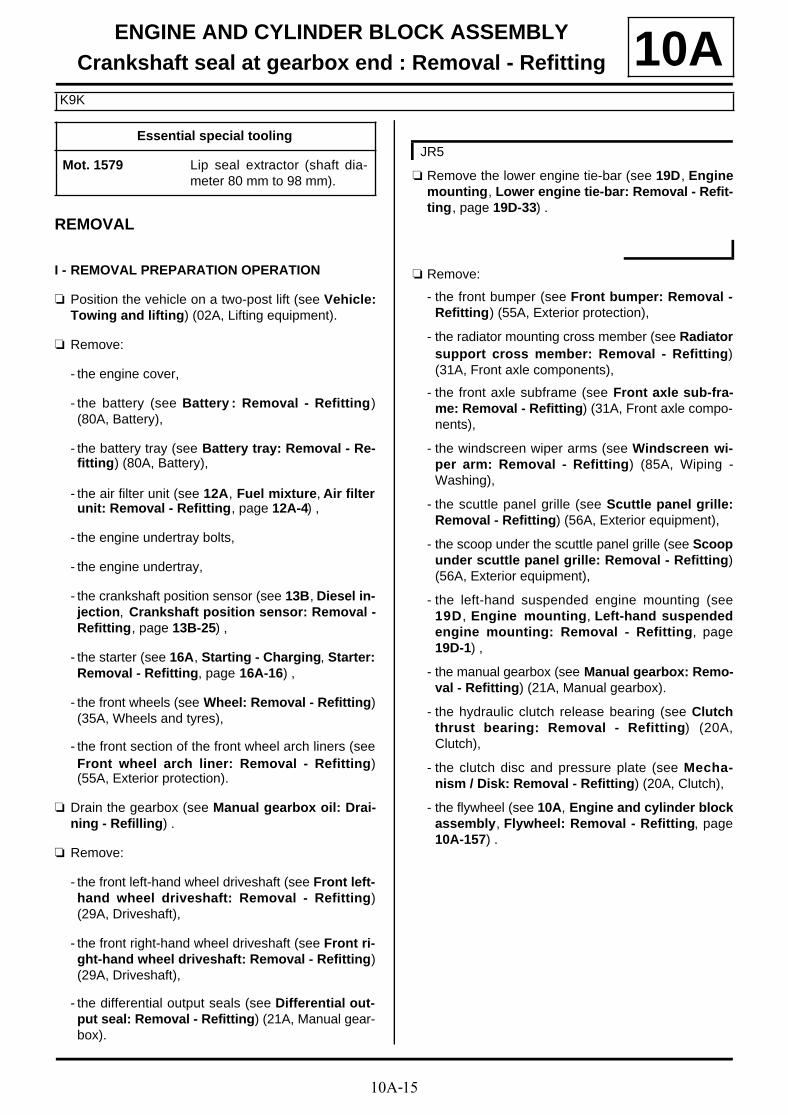
10AII - OPERATION FOR REMOVAL OF PART CONCERNED
a Fit the end piece (1) of the (Mot. 1579) (2) .
a Position the jaws (3) of the (Mot. 1579) on thecrankshaft (4) .
a Push the tool (Mot. 1579) until contact is madebetween the ends (5) of the jaws and the crankshaftseal.
a Move the jaws away by tightening the bolt (6) usingan open-jawed spanner.
105259
105265
105266
105267
10A-17
ENGINE AND CYLINDER BLOCK ASSEMBLYCrankshaft seal at gearbox end : Removal - Refitting
K9K
10A
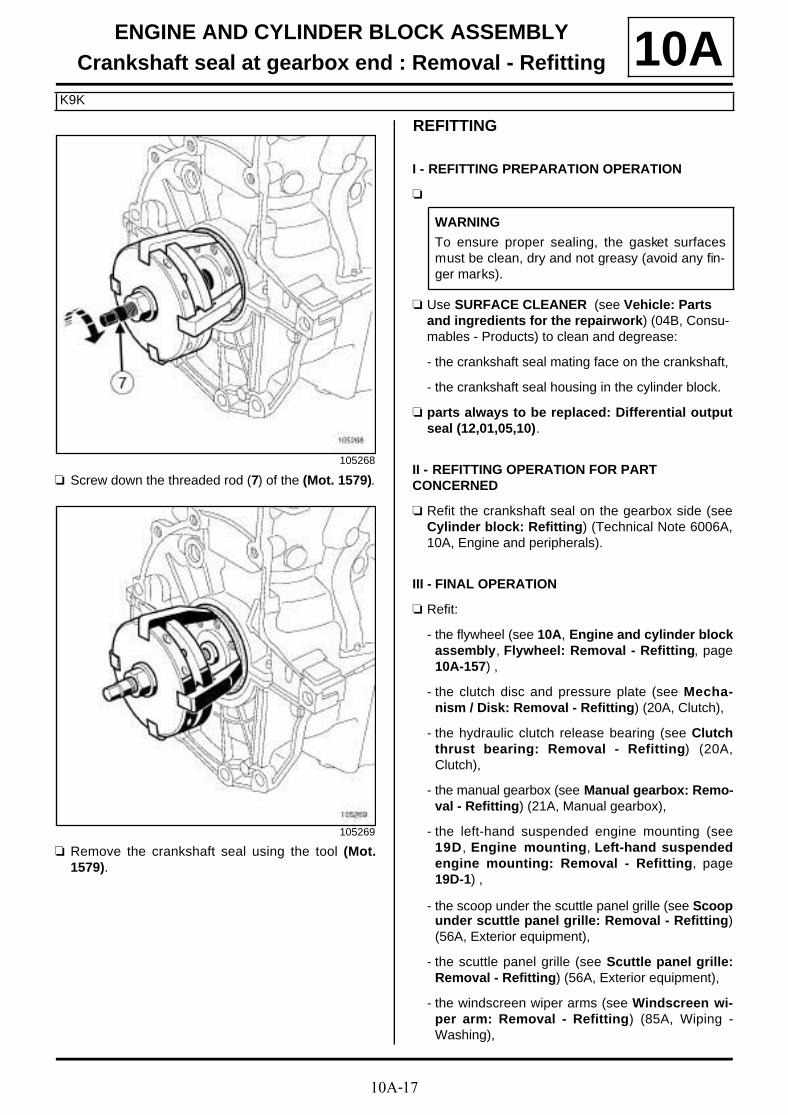
a Screw down the threaded rod (7) of the (Mot. 1579).
a Remove the crankshaft seal using the tool (Mot.1579).
REFITTING
I - REFITTING PREPARATION OPERATION
a
a Use SURFACE CLEANER (see Vehicle: Parts and ingredients for the repairwork) (04B, Consu-mables - Products) to clean and degrease:
- the crankshaft seal mating face on the crankshaft,
- the crankshaft seal housing in the cylinder block.
a parts always to be replaced: Differential outputseal (12,01,05,10).
II - REFITTING OPERATION FOR PART CONCERNED
a Refit the crankshaft seal on the gearbox side (seeCylinder block: Refitting) (Technical Note 6006A,10A, Engine and peripherals).
III - FINAL OPERATION
a Refit:
- the flywheel (see 10A, Engine and cylinder blockassembly, Flywheel: Removal - Refitting, page10A-157) ,
- the clutch disc and pressure plate (see Mecha-nism / Disk: Removal - Refitting) (20A, Clutch),
- the hydraulic clutch release bearing (see Clutchthrust bearing: Removal - Refitting) (20A,Clutch),
- the manual gearbox (see Manual gearbox: Remo-val - Refitting) (21A, Manual gearbox),
- the left-hand suspended engine mounting (see19D, Engine mounting, Left-hand suspendedengine mounting: Removal - Refitting, page19D-1) ,
- the scoop under the scuttle panel grille (see Scoopunder scuttle panel grille: Removal - Refitting)(56A, Exterior equipment),
- the scuttle panel grille (see Scuttle panel grille:Removal - Refitting) (56A, Exterior equipment),
- the windscreen wiper arms (see Windscreen wi-per arm: Removal - Refitting) (85A, Wiping -Washing),
105268
105269
WARNING
To ensure proper sealing, the gasket surfacesmust be clean, dry and not greasy (avoid any fin-ger marks).

10A-18
ENGINE AND CYLINDER BLOCK ASSEMBLYCrankshaft seal at gearbox end : Removal - Refitting
K9K
10A- the front axle subframe (see Front axle sub-fra-me: Removal - Refitting) (31A, Front axle compo-nents),
- the radiator mounting cross member (see Radiatorsupport cross member: Removal - Refitting)(31A, Front axle components),
- the front bumper (see Front bumper: Removal -Refitting) (55A, Exterior protection).
a Refit the lower engine tie-bar (see 19D, Enginemounting, Lower engine tie-bar: Removal - Refit-ting, page 19D-33) .
a Refit:
- the new differential output seals (see Differentialoutput seal: Removal - Refitting) (21A, Manualgearbox),
- the front right-hand wheel driveshaft (see Front ri-ght-hand wheel driveshaft: Removal - Refitting)(29A, Driveshafts),
- the front left-hand wheel driveshaft (see Front left-hand wheel driveshaft: Removal - Refitting)(29A, Driveshafts).
a Fill the manual gearbox (see Manual gearbox oil:Draining - Refilling) (21A, Manual gearbox).
a Refit:
- the front section of the front wheel arch liners (seeFront wheel arch liner: Removal - Refitting)(55A, Exterior protection),
- the front wheels (see Wheel: Removal - Refitting)(35A, Wheels and tyres),
- the starter (see 16A, Starting - Charging, Starter:Removal - Refitting, page 16A-16) ,
- the crankshaft position sensor (see 13B, Diesel in-jection, Crankshaft position sensor: Removal -Refitting, page 13B-25) .
a Bleed the clutch control circuit (see Clutch circuit:Bleeding) (37A, Mechanical component controls).
a Refit:
- the engine undertray,
- the air filter unit (see 12A, Fuel mixture, Air filterunit: Removal - Refitting, page 12A-4) ,
- the battery tray (see Battery tray: Removal - Re-fitting) (80A, Battery),
- the battery (see Battery : Removal - Refitting)(80A, Battery),
- the engine cover.
JR5

10A-19
ENGINE AND CYLINDER BLOCK ASSEMBLYCrankshaft seal at gearbox end : Removal - Refitting
F9Q
10A
REMOVAL
I - REMOVAL PREPARATION OPERATION
a Position the vehicle on a two-post lift (see Vehicle:Towing and lifting) (02A, Lifting equipment).
a Remove:
- the engine cover,
- the engine undertray bolts,
- the engine undertray,
- the battery (see Battery : Removal - Refitting)(80A, Battery),
- the battery tray (see Battery tray: Removal - Re-fitting) (80A, Battery),
- the air filter box (see 12A, Fuel mixture, Air filterunit: Removal - Refitting, page 12A-4) (12A, Fuelmixture),
- the hydraulic clutch control pipe (see Clutch cir-cuit: Removal - Refitting) (37A, Mechanical com-ponent controls),
- the starter (see 16A, Starting - Charging, Starter:Removal - Refitting, page 16A-16) ,
- the windscreen wiper blade arms (see Winds-creen wiper arm: Removal - Refitting) (85A, Wi-ping - Washing),
- the scuttle panel grille (see Scuttle panel grille:Removal - Refitting) (56A, Exterior equipment),
- the scoop under the scuttle panel grille (see Scoopunder scuttle panel grille: Removal - Refitting)(56A, Exterior equipment),
- the front wheels (see Wheel: Removal - Refitting)(35A, Wheels and tyres),
- the front wheel arch liners (see Front wheel archliner: Removal - Refitting) (55A, Exterior protec-tion).
a Drain the manual gearbox (see Manual gearboxoil: Draining - Refilling) (21A, Manual gearbox).
a Remove:
- the front right-hand wheel driveshaft (see Front ri-ght-hand wheel driveshaft: Removal - Refitting)(29A, Driveshaft),
- the front left-hand wheel driveshaft (see Front left-hand wheel driveshaft: Removal - Refitting)(29A, Driveshaft),
- the front bumper (see Front bumper: Removal -Refitting) (55A, Exterior protection),
- the radiator mounting cross member (see Radiatorsupport cross member: Removal - Refitting)(41A, Front lower structure),
- the engine tie-bar (see 19D, Engine mounting,Lower engine tie-bar: Removal - Refitting, page19D-33) ,
- the front axle subframe (see Front axle sub-fra-me: Removal - Refitting) (31A, Front axle compo-nents),
- the left-hand suspended engine mounting (see19D, Engine mounting, Left-hand suspendedengine mounting: Removal - Refitting, page19D-1) ,
- the manual gearbox (see Manual gearbox: Remo-val - Refitting) (21A, Manual gearbox),
- the « clutch pressure plate - disc » assembly (seeMechanism / Disk: Removal - Refitting) (21A,Manual gearbox),
- the flywheel (see 10A, Engine and cylinder blockassembly, Flywheel: Removal - Refitting, page10A-157) .
II - OPERATION FOR REMOVAL OF PART CONCERNED
a Remove the crankshaft seal on the gearbox sideusing a FLAT HEAD SCREWDRIVER and a woo-den block so as not to damage the crankshaft.
Essential special tooling
Mot. 991-01 Crankshaft oil seal fitting tool(flywhee l end) ( sea l85 x 105 x 8).
134483
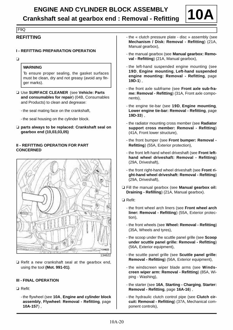
10A-20
ENGINE AND CYLINDER BLOCK ASSEMBLYCrankshaft seal at gearbox end : Removal - Refitting
F9Q
10AREFITTING
I - REFITTING PREPARATION OPERATION
a
a Use SURFACE CLEANER (see Vehicle: Parts and consumables for repair) (04B, Consumables and Products) to clean and degrease:
- the seal mating face on the crankshaft,
- the seal housing on the cylinder block.
a parts always to be replaced: Crankshaft seal ongearbox end (10,03,03,05)
II - REFITTING OPERATION FOR PART CONCERNED
a Refit a new crankshaft seal at the gearbox end,using the tool (Mot. 991-01).
III - FINAL OPERATION
a Refit:
- the flywheel (see 10A, Engine and cylinder blockassembly, Flywheel: Removal - Refitting, page10A-157) ,
- the « clutch pressure plate - disc » assembly (seeMechanism / Disk: Removal - Refitting) (21A,Manual gearbox),
- the manual gearbox (see Manual gearbox: Remo-val - Refitting) (21A, Manual gearbox),
- the left-hand suspended engine mounting (see19D, Engine mounting, Left-hand suspendedengine mounting: Removal - Refitting, page19D-1) ,
- the front axle subframe (see Front axle sub-fra-me: Removal - Refitting) (31A, Front axle compo-nents),
- the engine tie-bar (see 19D, Engine mounting,Lower engine tie-bar: Removal - Refitting, page19D-33) ,
- the radiator mounting cross member (see Radiatorsupport cross member: Removal - Refitting)(41A, Front lower structure),
- the front bumper (see Front bumper: Removal -Refitting) (55A, Exterior protection),
- the front left-hand wheel driveshaft (see Front left-hand wheel driveshaft: Removal - Refitting)(29A, Driveshaft),
- the front right-hand wheel driveshaft (see Front ri-ght-hand wheel driveshaft: Removal - Refitting)(29A, Driveshaft),
a Fill the manual gearbox (see Manual gearbox oil:Draining - Refilling) (21A, Manual gearbox).
a Refit:
- the front wheel arch liners (see Front wheel archliner: Removal - Refitting) (55A, Exterior protec-tion),
- the front wheels (see Wheel: Removal - Refitting)(35A, Wheels and tyres),
- the scoop under the scuttle panel grille (see Scoopunder scuttle panel grille: Removal - Refitting)(56A, Exterior equipment),
- the scuttle panel grille (see Scuttle panel grille:Removal - Refitting) (56A, Exterior equipment),
- the windscreen wiper blade arms (see Winds-creen wiper arm: Removal - Refitting) (85A, Wi-ping - Washing),
- the starter (see 16A, Starting - Charging, Starter:Removal - Refitting, page 16A-16) ,
- the hydraulic clutch control pipe (see Clutch cir-cuit: Removal - Refitting) (37A, Mechanical com-ponent controls),
WARNING
To ensure proper sealing, the gasket surfacesmust be clean, dry and not greasy (avoid any fin-ger marks).
134622

10A-21
ENGINE AND CYLINDER BLOCK ASSEMBLYCrankshaft seal at gearbox end : Removal - Refitting
F9Q
10A- the air filter box (see 12A, Fuel mixture, Air filterunit: Removal - Refitting, page 12A-4) (12A, Fuelmixture),
- the battery tray (see Battery tray: Removal - Re-fitting) (80A, Battery),
- the battery (see Battery : Removal - Refitting)(80A, Battery),
- the engine undertray,
- the engine cover.

10A-22
ENGINE AND CYLINDER BLOCK ASSEMBLYCrankshaft seal at gearbox end : Removal - Refitting
F4R
10A
REMOVAL
I - REMOVAL PREPARATION OPERATION
a Position the vehicle on a two-post lift (see Vehicle:Towing and lifting) (02A, Lifting equipment).
a Remove:
- the engine undertray bolts,
- the engine undertray,
- the engine cover,
- the battery (see Battery : Removal - Refitting)(80A, Battery),
- the battery tray (see Battery tray: Removal - Re-fitting) (80A, Battery),
- the air filter unit (see 12A, Fuel mixture, Air filterunit: Removal - Refitting, page 12A-4) ,
- the hydraulic clutch control pipe (see Clutch cir-cuit: Removal - Refitting) (37A, Mechanical com-ponent controls),
- the starter (see 16A, Starting - Charging, Starter:Removal - Refitting, page 16A-16) .
a Drain the manual gearbox oil (see Manual gearboxoil: Draining - Refilling) .
a Remove:
- the front wheels (see Wheel: Removal - Refitting)(35A, Wheels and tyres),
- the front section of the front wheel arch liners (seeFront wheel arch liner: Removal - Refitting)(55A, Exterior protection),
- the front bumper (see Front bumper: Removal -Refitting) (55A, Exterior protection),
- the radiator mounting cross member (see Radiatorsupport cross member: Removal - Refitting)(31A, Front axle components),
- the front right-hand wheel driveshaft (see Front ri-ght-hand wheel driveshaft: Removal - Refitting)(29A, Driveshafts),
- the front left-hand wheel driveshaft (see Front left-hand wheel driveshaft: Removal - Refitting)(29A, Driveshafts),
- the new differential output seals (see Differentialoutput seal: Removal - Refitting) (21A, Manualgearbox),
- the lower engine tie-bar (see 19D, Engine moun-ting, Lower engine tie-bar: Removal - Refitting,page 19D-33) ,
- the front axle subframe (see Front axle sub-fra-me: Removal - Refitting) (31A, Front axle compo-nents),
- the windscreen wiper arms (see Windscreen wi-per arm: Removal - Refitting) (85A, Wiping -Washing),
- the scuttle panel grille (see Scuttle panel grille:Removal - Refitting) (56A, Exterior equipment),
- the scoop under the scuttle panel grille (see Scoopunder scuttle panel grille: Removal - Refitting)(56A, Exterior equipment),
- the left-hand suspended engine mounting (see19D, Engine mounting, Left-hand suspendedengine mounting: Removal - Refitting, page19D-1) ,
- the manual gearbox (see Manual gearbox: Remo-val - Refitting) (21A, Manual gearbox).
- the « clutch pressure plate - disc » assembly (seeMechanism / Disk: Removal - Refitting) (20A,Clutch),
- the flywheel (see 10A, Engine and cylinder blockassembly, Flywheel: Removal - Refitting, page10A-157) .
Essential special tooling
Mot. 991-01 Crankshaft oil seal fitting tool(flywhee l end) ( sea l85 x 105 x 8).
IMPORTANT
To prevent the vehicle from falling, lash it to thevehicle lift using a strap.

10A-23
ENGINE AND CYLINDER BLOCK ASSEMBLYCrankshaft seal at gearbox end : Removal - Refitting
F4R
10AII - OPERATION FOR REMOVAL OF PART CONCERNED
a Remove the crankshaft seal on the gearbox sideusing a screwdriver and a wooden block.
REFITTING
I - REFITTING PREPARATION OPERATION
a parts always to be replaced: Crankshaft seal ongearbox end (10,03,03,05).
a Use SURFACE CLEANER (see Vehicle: Parts and ingredients for the repairwork) (04B, Consu-mables - Products) to clean and degrease:
- the mating face of the crankshaft seal on thecrankshaft at the gearbox end,
- the housing of the crankshaft seal on the cylinderblock at the gearbox end.
II - REFITTING OPERATION FOR PART CONCERNED
a Refit a new crankshaft seal at the gearbox end,using the tool (Mot. 991-01) (1) .
III - FINAL OPERATION
a Refit:
- the flywheel (see 10A, Engine and cylinder blockassembly, Flywheel: Removal - Refitting, page10A-157) ,
- the « clutch pressure plate - disc » assembly (seeMechanism / Disk: Removal - Refitting) (20A,Clutch),
- the manual gearbox (see Manual gearbox: Remo-val - Refitting) (21A, Manual gearbox),
- the left-hand suspended engine mounting (see19D, Engine mounting, Left-hand suspendedengine mounting: Removal - Refitting, page19D-1) ,
- the scoop under the scuttle panel grille (see Scoopunder scuttle panel grille: Removal - Refitting)(56A, Exterior equipment),
- the scuttle panel grille (see Scuttle panel grille:Removal - Refitting) (56A, Exterior equipment),
- the windscreen wiper arms (see Windscreen wi-per arm: Removal - Refitting) (85A, Wiping -Washing),
- the front axle subframe (see Front axle sub-fra-me: Removal - Refitting) (31A, Front axle compo-nents),
124127
Note:
Take care not to damage the crankshaft matingface.
WARNINGTo ensure proper sealing, the gasket surfacesmust be clean, dry and not greasy (avoid any fin-ger marks).
124128

10A-24
ENGINE AND CYLINDER BLOCK ASSEMBLYCrankshaft seal at gearbox end : Removal - Refitting
F4R
10A- the lower engine tie-bar (see 19D, Engine moun-ting, Lower engine tie-bar: Removal - Refitting,page 19D-33) ,
- the new differential output seals (see Differentialoutput seal: Removal - Refitting) (21A, Manualgearbox),
- the front left-hand wheel driveshaft (see Front left-hand wheel driveshaft: Removal - Refitting)(29A, Driveshafts),
- the front right-hand wheel driveshaft (see Front ri-ght-hand wheel driveshaft: Removal - Refitting)(29A, Driveshafts),
- the radiator mounting cross member (see Radiatorsupport cross member: Removal - Refitting)(31A, Front axle components),
- the front bumper (see Front bumper: Removal -Refitting) (55A, Exterior protection),
- the front section of the front wheel arch liners (seeFront wheel arch liner: Removal - Refitting)(55A, Exterior protection),
- the front wheels (see Wheel: Removal - Refitting)(35A, Wheels and tyres),
- the starter (see 16A, Starting - Charging, Starter:Removal - Refitting, page 16A-16) ,
- the hydraulic clutch control pipe (see Clutch cir-cuit: Removal - Refitting) (37A, Mechanical com-ponent controls).
a Perform the following operations:
- fill and top up the manual gearbox (see Manualgearbox oil: Draining - Refilling) (21A, Manualgearbox),
- bleed the hydraulic clutch control circuit (seeClutch circuit: Bleeding) (37A, Mechanical com-ponent controls).
a Refit:
- the air filter unit (see 12A, Fuel mixture, Air filterunit: Removal - Refitting, page 12A-4) ,
- the battery tray (see Battery tray: Removal - Re-fitting) (80A, Battery),
- the battery (see Battery: Removal - Refitting)(80A, Battery),
- the engine cover,
- the engine undertray.

10A-25
ENGINE AND CYLINDER BLOCK ASSEMBLYSump: Removal - Refitting
K4M
10A
REMOVAL
I - REMOVAL PREPARATION OPERATION
a Position the vehicle on a two-post lift (see Vehicle:Towing and lifting) (02A, Lifting equipment).
a Remove:
- the engine undertray bolts,
- the engine undertray.
a Remove:
- the dipstick guide bolt (1) from the lifting eye,
- the dipstick guide.
Tightening torquesm
sump bolts on the cylin-der block
14 N.m
sump bolts on the gear-box
44 N.m
bolt mounting the multi-function support on thesump
25 N.m
bolts 2 and 3 of therelay bearing
44 N.m
bolt 1 of the relay bea-ring
44 N.m
bolt 4 of the relay bea-ring flange
21 N.m
dipstick guide bolt onthe lifting eye
10 N.m
dipstick guide bolts onthe injector holder shim
10 N.m
IMPORTANT
Wear leaktight gloves (Nitrile type) for this opera-tion.
K4M, and 848
136454
10A-26
ENGINE AND CYLINDER BLOCK ASSEMBLYSump: Removal - Refitting
K4M
10A
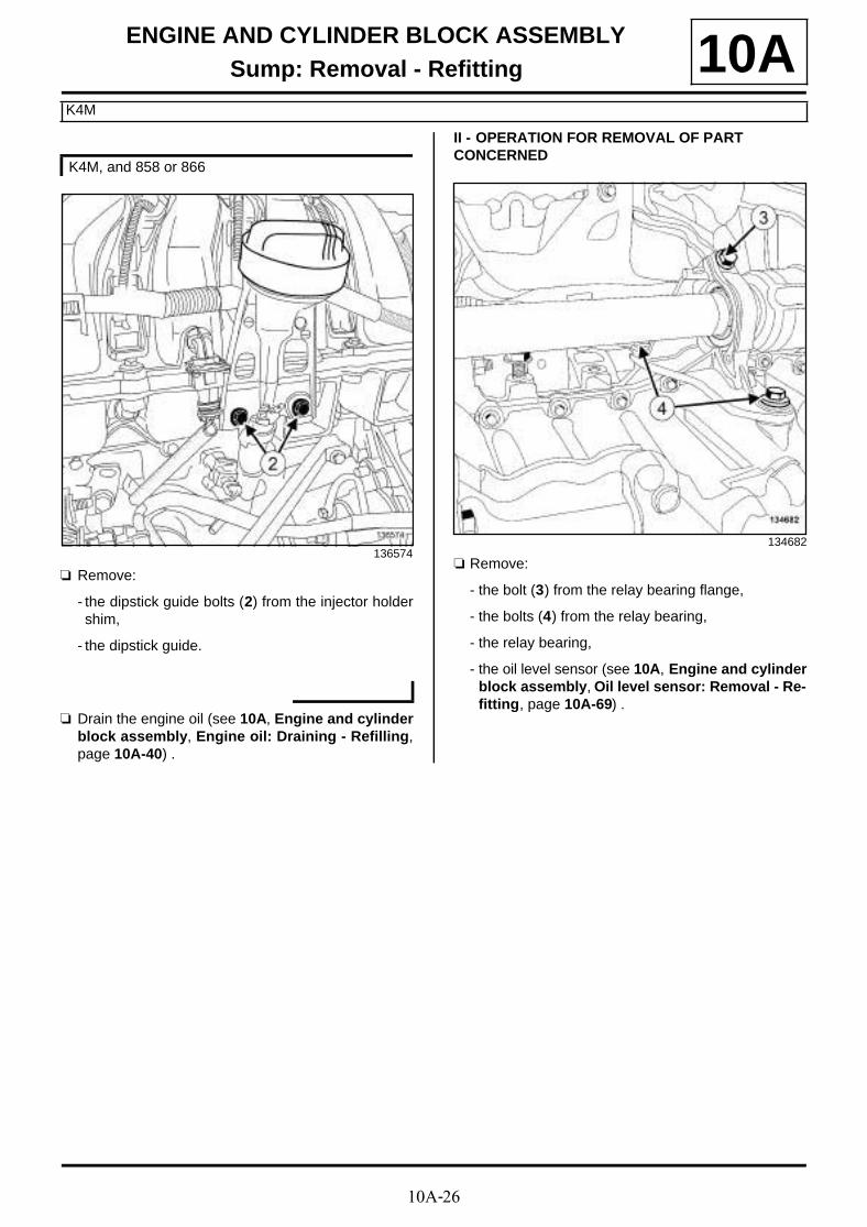
a Remove:
- the dipstick guide bolts (2) from the injector holdershim,
- the dipstick guide.
a Drain the engine oil (see 10A, Engine and cylinderblock assembly, Engine oil: Draining - Refilling,page 10A-40) .
II - OPERATION FOR REMOVAL OF PART CONCERNED
a Remove:
- the bolt (3) from the relay bearing flange,
- the bolts (4) from the relay bearing,
- the relay bearing,
- the oil level sensor (see 10A, Engine and cylinderblock assembly, Oil level sensor: Removal - Re-fitting, page 10A-69) .
K4M, and 858 or 866
136574134682

10A-27
ENGINE AND CYLINDER BLOCK ASSEMBLYSump: Removal - Refitting
K4M
10A
a
a Remove:
- the sump bolts (5) on the gearbox,
- the multifunction support bolt onto the sump,
- the sump bolts on the cylinder block,
- the sump,
- the sump seal.
REFITTING
I - REFITTING PREPARATION OPERATION
a parts always to be replaced: Engine oil sumpseal (10,03,01,09).
a Use SURFACE CLEANER (see Vehicle: Parts and ingredients for the repairwork) (04B, Consu-mables - Products) to clean and degrease:
- the sump joint face if it is to be reused,
- the cylinder block gasket face.
134543
134684
Note:
Prepare for the engine oil to drain out.
WARNING
To ensure proper sealing, the gasket surfacesmust be clean, dry and not greasy (avoid any fin-ger marks).
WARNING
Do not scrape the joint faces of the aluminium,any damage caused to the joint face will result ina risk of leaks.
10A-28
ENGINE AND CYLINDER BLOCK ASSEMBLYSump: Removal - Refitting
K4M
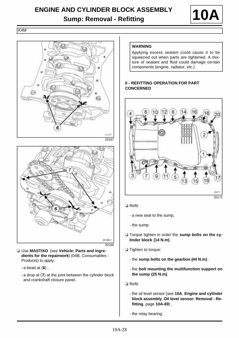
10A
a Use MASTIXO (see Vehicle: Parts and ingre-dients for the repairwork) (04B, Consumables - Products) to apply:
- a bead at (6) ,
- a drop at (7) at the joint between the cylinder blockand crankshaft closure panel.
II - REFITTING OPERATION FOR PART CONCERNED
a Refit:
- a new seal to the sump,
- the sump.
a Torque tighten in order the sump bolts on the cy-linder block (14 N.m).
a Tighten to torque:
- the sump bolts on the gearbox (44 N.m),
- the bolt mounting the multifunction support onthe sump (25 N.m).
a Refit:
- the oil level sensor (see 10A, Engine and cylinderblock assembly, Oil level sensor: Removal - Re-fitting, page 10A-69) ,
- the relay bearing.
20167
20166
WARNING
Applying excess sealant could cause it to besqueezed out when parts are tightened. A mix-ture of sealant and fluid could damage certaincomponents (engine, radiator, etc.).
20171
10A-29
ENGINE AND CYLINDER BLOCK ASSEMBLYSump: Removal - Refitting
K4M
10A
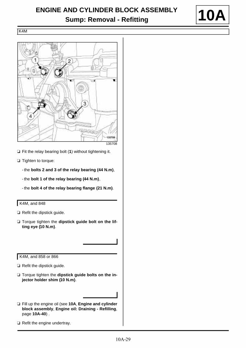
a Fit the relay bearing bolt (1) without tightening it.
a Tighten to torque:
- the bolts 2 and 3 of the relay bearing (44 N.m),
- the bolt 1 of the relay bearing (44 N.m),
- the bolt 4 of the relay bearing flange (21 N.m).
a Refit the dipstick guide.
a Torque tighten the dipstick guide bolt on the lif-ting eye (10 N.m).
a Refit the dipstick guide.
a Torque tighten the dipstick guide bolts on the in-jector holder shim (10 N.m).
a Fill up the engine oil (see 10A, Engine and cylinderblock assembly, Engine oil: Draining - Refilling,page 10A-40) .
a Refit the engine undertray.
135708
K4M, and 848
K4M, and 858 or 866

10A-30
ENGINE AND CYLINDER BLOCK ASSEMBLYSump: Removal - Refitting
F9Q
10A
REMOVAL
I - REMOVAL PREPARATION OPERATION
a Position the vehicle on a two-post lift (see Vehicle:Towing and lifting) (02A, Lifting equipment).
a Remove:
- the engine undertray bolts,
- the engine undertray.
a Drain the engine oil (see 10A, Engine and cylinderblock assembly, Engine oil: Draining - Refilling,page 10A-40) .
a Remove the engine tie-bar (see 19D , Enginemounting, Lower engine tie-bar: Removal - Refit-ting, page 19D-33) .
II - OPERATION FOR REMOVAL OF PART CONCERNED
a Disconnect the oil vapour rebreathing pipe (1) fromthe sump.
a Remove:
- the sump bolts (2) on the gearbox,
- the sump bolts on the cylinder block,
- the sump,
- the sump seal.
REFITTING
I - REFITTING PREPARATION OPERATION
a Always replace the sump gasket.
a Clean the cylinder block joint face using SUPERCLEANING AGENT FOR JOINT FACES (see Ve-hicle: Parts and ingredients for the repairwork)(04B, Consumables - Products).
a Use SURFACE CLEANER (see Vehicle: Parts and ingredients for the repairwork) (04B, Consu-mables - Products) to degrease:
- the sump joint face if it is to be reused,
- the cylinder block gasket face.
Tightening torquesm
sump bolts (A) to (F) 18 N.m
sump bolts (1) to (18) 15 N.m
120353
WARNING
Do not scrape the joint faces of the aluminium,any damage caused to the joint face will result ina risk of leaks.
WARNING
To ensure proper sealing, the gasket surfacesmust be clean, dry and not greasy (avoid any fin-ger marks).
WARNING
Applying excess sealant could cause it to besqueezed out when parts are tightened. A mix-ture of sealant and fluid could damage certaincomponents (engine, radiator, etc.).

10A-31
ENGINE AND CYLINDER BLOCK ASSEMBLYSump: Removal - Refitting
F9Q
10A
a
a Apply a BEAD OF SILICONE ADHESIVE SEA-LANT (see Vehicle: Parts and ingredients for therepairwork) (04B, Consumables - Products) to eachside of bearing No. 1 at (4) .
II - REFITTING OPERATION FOR PART CONCERNED
a Refit:
- a new seal to the sump,
- the sump.
a Tighten to torque and in order:
- the sump bolts (A) to (F) (18 N.m),
- the sump bolts (1) to (18) (15 N.m).
a Connect the oil vapour rebreathing pipe to the sump.
III - FINAL OPERATION
a Refit the engine tie-bar (see 19D, Engine moun-ting, Lower engine tie-bar: Removal - Refitting,page 19D-33) .
a Fill up with engine oil (see 10A, Engine and cylin-der block assembly, Engine oil: Draining - Refil-ling, page 10A-40) ,
a Refit the engine undertray.
15159
Note:
Do not cut the two tabs on the crankshaft closurepanel seal, which sit higher than the cylinderblock gasket face (3) .
15195

10A-32
ENGINE AND CYLINDER BLOCK ASSEMBLYSump: Removal - Refitting
F4R
10A
REMOVAL
I - REMOVAL PREPARATION OPERATION
a Position the vehicle on a two-post lift (see Vehicle:Towing and lifting) (02A, Lifting equipment).
a Remove:
- the engine undertray bolts,
- the engine undertray.
- the lower engine tie-bar (see 19D, Engine moun-ting, Lower engine tie-bar: Removal - Refitting,page 19D-33) .
a Remove:
- the lower engine tie-bar support bolts on the sump,
- the lower engine tie-bar support on the sump.
a Drain the engine oil (see 10A, Engine and cylinderblock assembly, Engine oil: Draining - Refilling,page 10A-40) .
II - OPERATION FOR REMOVAL OF PART CONCERNED
a Remove the bolts (2) from the sump on the manualgearbox.
Tightening torquesm
sump bolts 15 N.m
sump bolts on themanual gearbox
44 N.m
lower engine tie-barsupport bolts
62 N.m
136504
135762
135763

10A-33
ENGINE AND CYLINDER BLOCK ASSEMBLYSump: Removal - Refitting
F4R
10Aa
a Remove:
- the sump bolts on the cylinder block,
- the sump,
- the sump seal.
REFITTING
I - REFITTING PREPARATION OPERATION
a parts always to be replaced: Engine oil sumpseal (10,03,01,09).
a Use SURFACE CLEANER (see Vehicle: Parts and ingredients for the repairwork) (04B, Consu-mables - Products) to clean and degrease:
- the sump joint face if it is to be reused,
- the cylinder block gasket face.
135760
135761
135764
WARNING
Prepare for the flow of fluid, and protect the sur-rounding components.
WARNING
Do not scrape the joint faces of the aluminium,any damage caused to the joint face will result ina risk of leaks.
WARNING
To ensure proper sealing, the gasket surfacesmust be clean, dry and not greasy (avoid any fin-ger marks).

10A-34
ENGINE AND CYLINDER BLOCK ASSEMBLYSump: Removal - Refitting
F4R
10A
a Apply a bead of MASTIXO (see Vehicle: Parts and ingredients for the repairwork) (04B, Consuma-bles - Products):
- at (A) on each side of bearing no.1,
- at (B) at the joint between the cylinder block andcrankshaft closure panel.
II - REFITTING OPERATION FOR PART CONCERNED
a Refit:
- a new seal to the sump,
- the sump.
a Tighten to torque and in order:
- the sump bolts (15 N.m),
- the sump bolts on the manual gearbox (44 N.m).
a Refit the lower engine tie-bar support.
a Torque tighten the lower engine tie-bar supportbolts (62 N.m).
III - FINAL OPERATION
a Refit:
- the lower engine tie-bar (see 19D, Engine moun-ting, Lower engine tie-bar: Removal - Refitting,page 19D-33) ,
- the engine undertray.
a Fill up the engine oil, observing the quantity of oil re-commended by the manufacturer (see 10A, Engineand cylinder block assembly, Engine oil: Drai-ning - Refilling, page 10A-40) .
a Check the oil level using the dipstick.
a Adjust the engine oil level if necessary.
15159
WARNING
Applying excess sealant could cause it to besqueezed out when parts are tightened. A mix-ture of sealant and fluid could damage certaincomponents (engine, radiator, etc.).
15195

10A-35
ENGINE AND CYLINDER BLOCK ASSEMBLYSump: Removal - Refitting
K9K
10A
REMOVAL
I - REMOVAL PREPARATION OPERATION
a Position the vehicle on a two-post lift (see Vehicle:Towing and lifting) (02A, Lifting equipment).
a Remove:
- the engine cover,
- the dipstick,
- the engine undertray bolts,
- the engine undertray.
a Drain the engine oil (see 10A, Engine and cylinderblock assembly, Engine oil: Draining - Refilling,page 10A-40) .
a Remove the lower engine tie-bar (see 19D, Enginemounting, Lower engine tie-bar: Removal - Refit-ting, page 19D-33) .
a Remove:
- the bolts (1) from the front right-hand wheel drives-haft relay bearing,
- the front right-hand wheel driveshaft relay bearing.
a Remove the lower bolt (2) from the multifunctionsupport.
Tightening torquesm
sump bolts 14 N.m
sump bolts on the gear-box
44 N.m
catalytic converter ups-tream strut bolt on thecylinder block
50 N.m
catalytic converter ups-tream strut bolts on thecatalytic converter
26 N.m
multifunction supportlower bolt
25 N.m
front right-hand wheeldriveshaft relay bearingbolts
44 N.m
IMPORTANT
Wear leaktight gloves (Nitrile type) for this opera-tion.
123838
123832
10A-36
ENGINE AND CYLINDER BLOCK ASSEMBLYSump: Removal - Refitting
K9K
10A
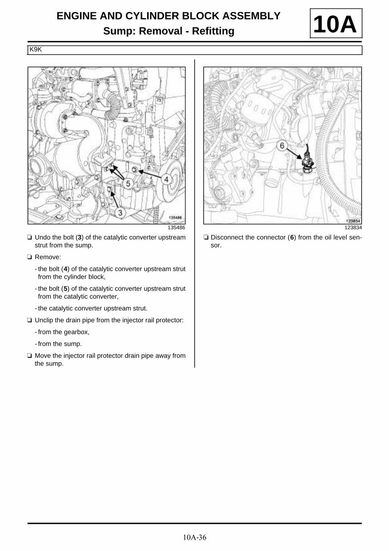
a Undo the bolt (3) of the catalytic converter upstreamstrut from the sump.
a Remove:
- the bolt (4) of the catalytic converter upstream strutfrom the cylinder block,
- the bolt (5) of the catalytic converter upstream strutfrom the catalytic converter,
- the catalytic converter upstream strut.
a Unclip the drain pipe from the injector rail protector:
- from the gearbox,
- from the sump.
a Move the injector rail protector drain pipe away fromthe sump.
a Disconnect the connector (6) from the oil level sen-sor.
135486 123834
10A-37
ENGINE AND CYLINDER BLOCK ASSEMBLYSump: Removal - Refitting
K9K
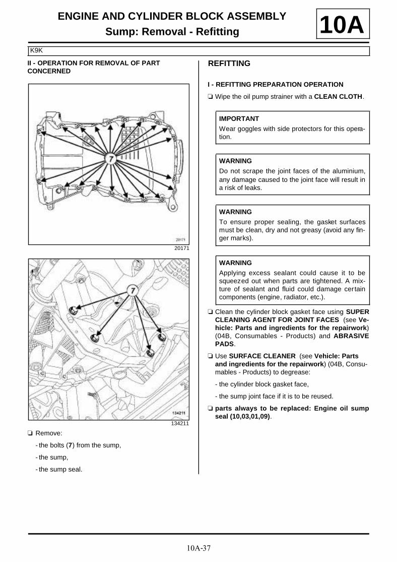
10AII - OPERATION FOR REMOVAL OF PART CONCERNED
a Remove:
- the bolts (7) from the sump,
- the sump,
- the sump seal.
REFITTING
I - REFITTING PREPARATION OPERATION
a Wipe the oil pump strainer with a CLEAN CLOTH.
a Clean the cylinder block gasket face using SUPERCLEANING AGENT FOR JOINT FACES (see Ve-hicle: Parts and ingredients for the repairwork)(04B, Consumables - Products) and ABRASIVEPADS.
a Use SURFACE CLEANER (see Vehicle: Parts and ingredients for the repairwork) (04B, Consu-mables - Products) to degrease:
- the cylinder block gasket face,
- the sump joint face if it is to be reused.
a parts always to be replaced: Engine oil sumpseal (10,03,01,09).
20171
134211
IMPORTANT
Wear goggles with side protectors for this opera-tion.
WARNING
Do not scrape the joint faces of the aluminium,any damage caused to the joint face will result ina risk of leaks.
WARNING
To ensure proper sealing, the gasket surfacesmust be clean, dry and not greasy (avoid any fin-ger marks).
WARNING
Applying excess sealant could cause it to besqueezed out when parts are tightened. A mix-ture of sealant and fluid could damage certaincomponents (engine, radiator, etc.).

10A-38
ENGINE AND CYLINDER BLOCK ASSEMBLYSump: Removal - Refitting
K9K
10A
a Apply:
- four beads of SILICONE ADHESIVE SEALANT(6) (see Vehicle: Parts and ingredients for therepairwork) (04B, Consumables - Products) with adiameter of 5 mm and a length of 12 mm,
- two drops of SILICONE ADHESIVE SEALANT (7)(see Vehicle: Parts and ingredients for the re-pairwork) (04B, Consumables - Products) with adiameter of 5 mm.
If replacing the sump
a Remove the oil level sensor from the sump.
a Refit the oil level sensor to the new sump.
II - REFITTING OPERATION FOR PART CONCERNED
a Fit:
- a new sump seal to the sump,
- the sump fitted with a new seal.
a Refit:
- the sump bolts to the cylinder block in the correctorder,
- the sump bolts on the gearbox.
a Tighten to torque:
- and in order, the sump bolts (14 N.m),
- the sump bolts on the gearbox (44 N.m).
III - FINAL OPERATION
a Connect the connector to the oil level sensor.
a Fit the injector rail protector drain pipe.
a Clip the injector rail protector drain pipe onto:
- the sump,
- the gearbox.
a Refit the catalytic converter upstream strut.
a Tighten to torque:
- the catalytic converter upstream strut bolt onthe cylinder block (50 N.m),
20166
20167
20171

10A-39
ENGINE AND CYLINDER BLOCK ASSEMBLYSump: Removal - Refitting
K9K
10A- the catalytic converter upstream strut bolts onthe catalytic converter (26 N.m).
a Tighten the catalytic converter upstream strut bolt onthe sump.
a Torque tighten the multifunction support lowerbolt (25 N.m).
a Refit the relay bearing of the front right-hand wheeldriveshaft.
a Torque tighten the front right-hand wheel drives-haft relay bearing bolts (44 N.m).
a Refit the lower engine tie-bar (see 19D, Enginemounting, Lower engine tie-bar: Removal - Refit-ting, page 19D-33) .
a Fill up the engine oil (see 10A, Engine and cylinderblock assembly, Engine oil: Draining - Refilling,page 10A-40) .
a Refit:
- the engine undertray,
- the dipstick,
- the engine cover.
10A-40
ENGINE AND CYLINDER BLOCK ASSEMBLYEngine oil: Draining - Refilling
K9K
10A
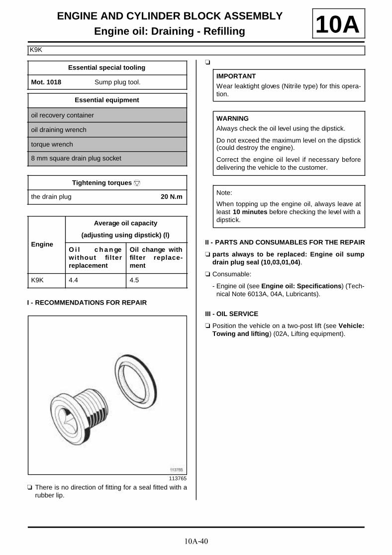
I - RECOMMENDATIONS FOR REPAIR
a There is no direction of fitting for a seal fitted with arubber lip.
a
II - PARTS AND CONSUMABLES FOR THE REPAIR
a parts always to be replaced: Engine oil sumpdrain plug seal (10,03,01,04).
a Consumable:
- Engine oil (see Engine oil: Specifications) (Tech-nical Note 6013A, 04A, Lubricants).
III - OIL SERVICE
a Position the vehicle on a two-post lift (see Vehicle:Towing and lifting) (02A, Lifting equipment).
Essential special tooling
Mot. 1018 Sump plug tool.
Essential equipment
oil recovery container
oil draining wrench
torque wrench
8 mm square drain plug socket
Tightening torquesm
the drain plug 20 N.m
Engine
Average oil capacity
(adjusting using dipstick) (l)
O i l c h a n gewithout filterreplacement
Oil change withfilter replace-ment
K9K 4.4 4.5
113765
IMPORTANT
Wear leaktight gloves (Nitrile type) for this opera-tion.
WARNING
Always check the oil level using the dipstick.
Do not exceed the maximum level on the dipstick(could destroy the engine).
Correct the engine oil level if necessary beforedelivering the vehicle to the customer.
Note:
When topping up the engine oil, always leave atleast 10 minutes before checking the level with adipstick.

10A-41
ENGINE AND CYLINDER BLOCK ASSEMBLYEngine oil: Draining - Refilling
K9K
10A
a Remove:
- the engine oil filler cap (1) ,
- the dipstick (2) ,
- the engine undertray bolts,
- the engine undertray.
a Place the oil recovery container under the engine.
a Remove the drain plug (3) from the engine oil sumpusing the tool (Mot. 1018) or a oil draining wrench.
a Let the engine oil flow out.
a Remove the drain plug seal.
a Refit a new seal on the drain plug.
a Screw the drain plug onto the engine oil sump.
a Torque tighten the drain plug (20 N.m) using a tor-que wrench and a 8 mm square drain plug soc-ket.
a Use a cloth to wipe away any oil drips on the engineoil sump.
a Remove the oil recovery container.
a Refit the engine undertray.
IV - FILLING
a Position the vehicle back on the ground.
a Fill with engine oil, observing the type of engine oilrecommended by the manufacturer (see Engine oil:Specifications) (Technical Note 6013A, 04A, Lubri-cants).
a Wait at least 10 minutes.
a Check the oil level using the dipstick.
a Top up the engine oil level if necessary.
a Refit:
- the engine oil filler cap,
- the dipstick.
136735
135627
10A-42
ENGINE AND CYLINDER BLOCK ASSEMBLYEngine oil: Draining - Refilling
F4R
10A
I - RECOMMENDATIONS FOR REPAIR
a
II - PARTS AND CONSUMABLES FOR THE REPAIR
a parts always to be replaced: Engine oil sumpdrain plug seal (10,03,01,04).
a Consumable:
- Engine oil (see Engine oil: Specifications) (Tech-nical Note 6013A, 04A, Lubricants).
III - OIL SERVICE
a Position the vehicle on a two-post lift (see Vehicle:Towing and lifting) (02A, Lifting equipment).
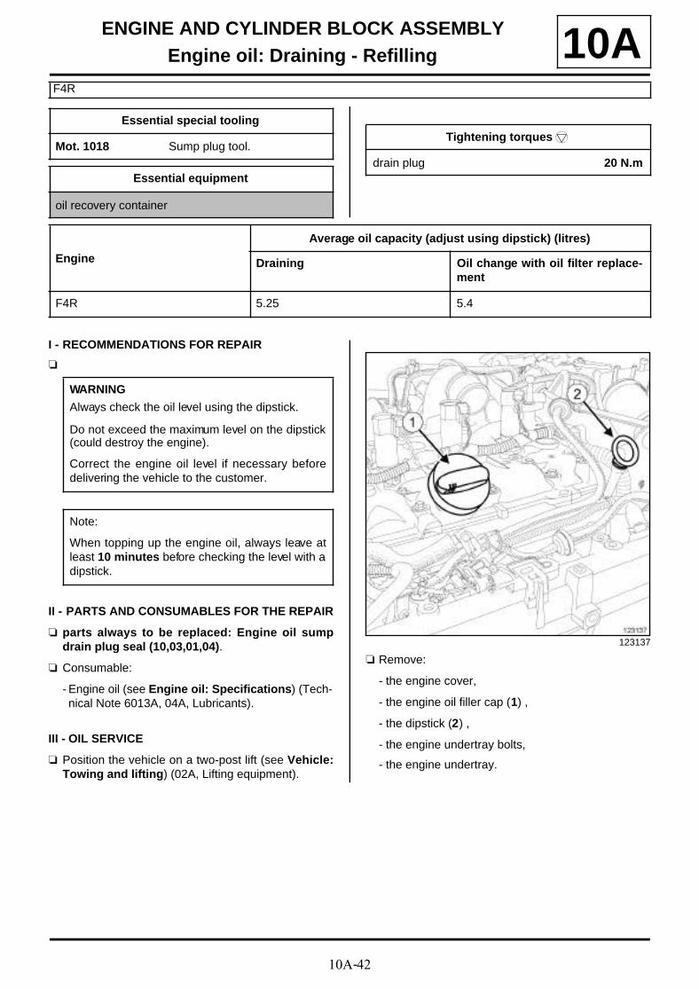
a Remove:
- the engine cover,
- the engine oil filler cap (1) ,
- the dipstick (2) ,
- the engine undertray bolts,
- the engine undertray.
Essential special tooling
Mot. 1018 Sump plug tool.
Essential equipment
oil recovery container
Tightening torquesm
drain plug 20 N.m
Engine
Average oil capacity (adjust using dipstick) (litres)
Draining Oil change with oil filter replace-ment
F4R 5.25 5.4
WARNING
Always check the oil level using the dipstick.
Do not exceed the maximum level on the dipstick(could destroy the engine).
Correct the engine oil level if necessary beforedelivering the vehicle to the customer.
Note:
When topping up the engine oil, always leave atleast 10 minutes before checking the level with adipstick.
123137

10A-43
ENGINE AND CYLINDER BLOCK ASSEMBLYEngine oil: Draining - Refilling
F4R
10A
a Place the oil recovery container under the engine.
a Remove:
- the drain plug (3) from the engine oil sump usingthe (Mot. 1018),
- the sump drain plug seal.
a Let the engine oil flow out.
a Refit:
- a new seal (4) on the sump drain plug,
- the drain plug on the sump.
a Torque tighten the drain plug (20 N.m).
a Clean the traces of oil around the drain plug so thatany possible leaks can be detected.
a Remove the oil recovery container.
IV - FILLING
a Position the vehicle back on the ground.
a Fill the engine with oil, observing the recommendedamount.
a Wait for at least 10 minutes.
a Check the oil level using the dipstick.
a Adjust the engine oil level if necessary.
a Refit:
- the engine oil filler cap,
- the dipstick,
- the engine cover,
- the engine undertray.123178
113765

10A-44
ENGINE AND CYLINDER BLOCK ASSEMBLYEngine oil: Draining - Refilling
K4M
10A
I - RECOMMENDATIONS FOR REPAIR
a
II - PARTS AND CONSUMABLES FOR THE REPAIR
a parts always to be replaced: Engine oil sumpdrain plug seal (10,03,01,04).
a Consumable:
- Engine oil (see Engine oil: Specifications) (Tech-nical Note 6013A, 04A, Lubricants).
III - DRAINING
a Position the vehicle on a two-post lift (see Vehicle:Towing and lifting) (02A, Lifting equipment).
a Remove:
- the engine cover,
- the engine oil filler cap (1) ,
- the dipstick (2) .
Essential special tooling
Mot. 1018 Sump plug tool.
Essential equipment
oil recovery container
Tightening torquesm
drain plug 20 N.m
Engine
Average oil capacity (adjust using dipstick) (litres)
Draining Oil change plus oil filter replace-ment
K4M 4.7 4.8
WARNING
Always check the oil level using the dipstick.
Do not exceed the maximum level on the dipstick(could destroy the engine).
Correct the engine oil level if necessary beforedelivering the vehicle to the customer.
Note:
When filling up the engine oil, always leave atleast 10 minutes for the oil to drain down beforechecking the level with a dipstick.
136480

10A-45
ENGINE AND CYLINDER BLOCK ASSEMBLYEngine oil: Draining - Refilling
K4M
10A
a Remove:
- the engine undertray bolts,
- the engine undertray.
a Place the oil recovery container under the engine.
a Remove:
- the drain plug (3) from the engine oil sump usingthe (Mot. 1018),
- the engine oil sump drain plug seal.
a Let the engine oil flow out.
a Refit:
- a new seal on the sump drain plug,
- the drain plug on the sump.
a Torque tighten the drain plug (20 N.m).
a Clean the traces of oil around the drain plug so thatany possible leaks can be detected.
a Remove the oil recovery container.
IV - FILLING
a Position the vehicle back on the ground.
a Fill the engine with oil, observing the recommendedamount.
a Wait at least 10 minutes.
a Check the oil level using the dipstick.
a Adjust the engine oil level if necessary.
a Refit:
- the engine oil filler cap,
- the dipstick,
- the engine cover,
- the engine undertray.
136474 113765

10A-46
ENGINE AND CYLINDER BLOCK ASSEMBLYEngine oil: Draining - Refilling
F9Q
10A
I - PARTS AND CONSUMABLES FOR THE REPAIR
a parts always to be replaced: Engine oil sumpdrain plug seal (10,03,01,04)
a Consumable:
- engine oil (see Diesel engine oils: Specifica-tions) (Technical Note 6013A, 04A, Lubricants).
II - OIL SERVICE
a Position the vehicle on a two-post lift (see Vehicle:Towing and lifting) (02A, Lifting equipment).
a Remove:
- the « oil filler cap - dipstick » assembly (1) ,
- the engine undertray bolts,
- the engine undertray.
a Place a oil recovery container underneath the en-gine oil drain plug.
Essential special tooling
Mot. 1018 Sump plug tool.
Essential equipment
oil recovery container
Tightening torquesm
drain plug 20 N.m
Engine Suffix
Average oil capacity (check and adjust with dipstick) (l)
Oil changewithout filterreplacement
Oil changew i t h filterreplacement
F9Q870
4.7 5.1872
IMPORTANT
Wear leaktight gloves (Nitrile type) for this opera-tion.
WARNING
Always check the oil level using the dipstick.
Do not exceed the maximum level on the dipstick(could destroy the engine).
Correct the engine oil level if necessary before deli-vering the vehicle to the customer.
Note:
When topping up the engine oil, always leave atleast 10 minutes before checking the level with adipstick.
136190
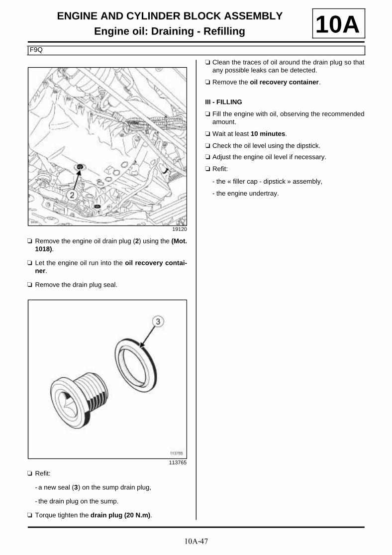
10A-47
ENGINE AND CYLINDER BLOCK ASSEMBLYEngine oil: Draining - Refilling
F9Q
10A
a Remove the engine oil drain plug (2) using the (Mot.1018).
a Let the engine oil run into the oil recovery contai-ner.
a Remove the drain plug seal.
a Refit:
- a new seal (3) on the sump drain plug,
- the drain plug on the sump.
a Torque tighten the drain plug (20 N.m).
a Clean the traces of oil around the drain plug so thatany possible leaks can be detected.
a Remove the oil recovery container.
III - FILLING
a Fill the engine with oil, observing the recommendedamount.
a Wait at least 10 minutes.
a Check the oil level using the dipstick.
a Adjust the engine oil level if necessary.
a Refit:
- the « filler cap - dipstick » assembly,
- the engine undertray.
19120
113765

10A-48
ENGINE AND CYLINDER BLOCK ASSEMBLYOil filter: Removal - Refitting
K9K
10A
REMOVAL
I - REMOVAL PREPARATION OPERATION
a Position the vehicle on a two-post lift (see Vehicle:Towing and lifting) (02A, Lifting equipment).
a Remove:
- the engine undertray bolts,
- the engine undertray.
a Place a oil recovery container underneath the en-gine.
II - OPERATION FOR REMOVAL OF PART CONCERNED
a Remove the oil filter (1) using the tool (Mot. 1329)(2)
REFITTING
I - REFITTING PREPARATION OPERATION
a parts always to be replaced: Oil filter (10,05,05,03).
a Lubricate the new oil filter seal with new engine oil.
II - REFITTING OPERATION FOR PART CONCERNED
a Refit a new oil filter by hand until the oil filter seal co-mes into contact with the oil filter support.
a Tighten the new oil filter 3/4 of a turn by hand orusing the (Mot. 1329).
III - FINAL OPERATION
a Wipe any oil run-off with a cloth.
a Top up the oil level in the engine using oil recom-mended by the manufacturer (see Engine oil: Spe-cifications) (Technical Note 6013A, 04A,Lubricants).
a Start the engine and leave it running for approxima-tely 30 seconds.
a Check there are no leaks from the oil filter.
a Remove the oil recovery container.
a Refit:
- the engine undertray,
- the engine undertray bolts.
a Wait at least 10 minutes.
Essential special tooling
Mot. 1329 Oil filter removing tool (76mm diameter).
Essential equipment
oil recovery container
IMPORTANT
Wear leaktight gloves (Nitrile type) for this opera-tion.
WARNING
Always check the oil level using the dipstick.
Do not exceed the maximum level on the dipstick(could destroy the engine).
Correct the engine oil level if necessary before deli-vering the vehicle to the customer.
Note:
When topping up the engine oil, always leave atleast 10 minutes before checking the level with adipstick.
97160

10A-49
ENGINE AND CYLINDER BLOCK ASSEMBLYOil filter: Removal - Refitting
K9K
10Aa Check the oil level using the dipstick.
a Adjust the engine oil level if necessary.
Note:
The engine oil level must be between the “mini-mum” and “maximum” marks on the dipstick.

10A-50
ENGINE AND CYLINDER BLOCK ASSEMBLYOil filter: Removal - Refitting
K4M
10A
REMOVAL
I - REMOVAL PREPARATION OPERATION
a Position the vehicle on a two-post lift (see Vehicle:Towing and lifting) (02A, Lifting equipment).
a Remove:
- the engine undertray bolts,
- the engine undertray.
a Place the oil recovery container under the engine.
II - OPERATION FOR REMOVAL OF PART CONCERNED
a Remove the oil filter using the (Mot. 1329).
REFITTING
I - REFITTING PREPARATION OPERATION
a parts always to be replaced: Oil filter (10,05,05,03).
a Use SURFACE CLEANER (see Vehicle: Precau-tions for repair) (04B, Consumables - Products) toclean and degrease the cylinder block joint face.
a Lubricate the oil filter seal with new engine oil.
II - REFITTING OPERATION FOR PART CONCERNED
a Fit a new oil filter.
a Tighten the oil filter until it makes contact.
a Manually tighten the oil filter by 3/4 of a turn.
III - FINAL OPERATION
a Remove the oil recovery container.
a Wipe any oil run-off with a cloth.
a Top up the engine oil with oil recommended by themanufacturer (see Engine oil: Specifications)(Technical Note 6013A, 04A, Lubricants).
a Start the engine and wait until the oil pressure war-ning light goes out on the instrument panel.
Essential special tooling
Mot. 1329 Oil filter removing tool (76mm diameter).
Essential equipment
oil recovery container
IMPORTANT
Wear leaktight gloves (Nitrile type) for this opera-tion.
WARNING
Always check the oil level using the dipstick.
Do not exceed the maximum level on the dipstick(could destroy the engine).
Correct the engine oil level if necessary before deli-vering the vehicle to the customer.
Note:
When filling up the engine oil, always leave at least10 minutes for the oil to drain down before checkingwith a dipstick.
When removing the oil filter, check that the oil filterseal is not still stuck to the cylinder block or the oilfilter support.
137350

10A-51
ENGINE AND CYLINDER BLOCK ASSEMBLYOil filter: Removal - Refitting
K4M
10Aa Check for leaks from the oil filter.
a Refit the engine undertray.
a Wait at least 10 minutes.
a Check the oil level using the dipstick.
a Adjust the engine oil level if necessary.

10A-52
ENGINE AND CYLINDER BLOCK ASSEMBLYOil filter: Removal - Refitting
F4R
10A
REMOVAL
I - REMOVAL PREPARATION OPERATION
a Position the vehicle on a two-post lift (see Vehicle:Towing and lifting) (02A, Lifting equipment).
a Remove:
- the engine cover,
- the engine undertray bolts,
- the engine undertray.
a Place the oil recovery container under the engine.
II - OPERATION FOR REMOVAL OF PART CONCERNED
a Remove the oil filter (1) using the tool (Mot. 1329)
REFITTING
I - REFITTING PREPARATION OPERATION
a Use BRAKE CLEANER (see Vehicle: Parts andingredients for the repairwork) (04B Consuma-bles - Products) to clean and degrease the gasketsurface of the oil-water heat exchanger.
a parts always to be replaced: Oil filter (10,05,05,03).
a Lubricate the new oil filter seal with new engine oil.
II - REFITTING OPERATION FOR PARTS CONCERNED
a Fit a new oil filter.
a Tighten the oil filter until it makes contact.
a Tighten the oil filter by 3/4 of a turn.
III - FINAL OPERATION
a Wipe any oil run-off with a cloth.
Essential special tooling
Mot. 1329 Oil filter removing tool (76mm diameter).
Essential equipment
oil recovery container
IMPORTANT
Wear leaktight gloves (Nitrile type) for this opera-tion.
WARNING
Always check the oil level using the dipstick.
Do not exceed the maximum level on the dipstick(could destroy the engine).
Correct the engine oil level if necessary before deli-vering the vehicle to the customer.
Note:
When topping up the engine oil, always leave atleast 10 minutes before checking the level with adipstick.
When removing the oil filter, check that the oil filterseal is not still stuck to the cylinder block or oil filtermounting.
136525
WARNING
To ensure proper sealing, the gasket surfacesmust be clean, dry and not greasy (avoid any fin-ger marks).

10A-53
ENGINE AND CYLINDER BLOCK ASSEMBLYOil filter: Removal - Refitting
F4R
10Aa Top up the engine oil with oil recommended by the
manufacturer (see Vehicle: Parts and ingredientsfor the repairwork) (04B Consumables - Products).
a Start the engine and wait until the oil pressure war-ning light goes out on the instrument panel.
a Check for leaks from the oil filter.
a Remove the oil recovery container.
a Refit the engine undertray.
a Wait at least 10 minutes.
a Check the oil level using the dipstick.
a Adjust the engine oil level if necessary.

10A-54
ENGINE AND CYLINDER BLOCK ASSEMBLYOil filter: Removal - Refitting
F9Q
10A
REMOVAL
I - REMOVAL PREPARATION OPERATION
a Position the vehicle on a two-post lift (see Vehicle:Towing and lifting) (02A, Lifting equipment).
a Remove:
- the engine undertray bolts,
- the engine undertray.
a Fit a oil recovery container under the engine.
II - OPERATION FOR REMOVAL OF PART CONCERNED
a Remove the oil filter using the (Mot. 1280-01) (1) .
REFITTING
I - REFITTING PREPARATION OPERATION
a Use SURFACE CLEANER (see Vehicle: Partsand ingredients for the repairwork) (04B, Consu-mables - Products) to clean and degrease the cylin-der block joint face.
a parts always to be replaced: Oil filter (10,05,05,03).
a Lubricate the new oil filter seal with new engine oil.
II - REFITTING OPERATION FOR PART CONCERNED
a Fit a new oil filter.
a Tighten the oil filter until it makes contact.
a Tighten the oil filter by 3/4 of a turn.
III - FINAL OPERATION
a Remove the oil recovery container.
a Wipe any oil run-off with a cloth.
a Top up the engine oil with oil recommended by themanufacturer (see Engine oil: Specifications)(Technical Note 6013A, 04A, Lubricants).
a Start the engine and wait until the oil pressure war-ning light goes out on the instrument panel.
a Check that there are no leaks from the oil filter.
a Refit the engine undertray.
a Wait at least 10 minutes.
a Check the oil level using the dipstick.
a Adjust the engine oil level if necessary.
Essential special tooling
Mot. 1280-01 Oil filter removing tool, 86 mmdiameter.
Essential equipment
oil recovery container
136207

10A-55
ENGINE AND CYLINDER BLOCK ASSEMBLYExchanger: Removal - Refitting
K9K
10AREMOVAL
I - REMOVAL PREPARATION OPERATION
a Position the vehicle on a two-post lift (see Vehicle:Towing and lifting) (02A, Lifting equipment).
a Remove:
- the engine cover,
- the front wheels (see Wheel: Removal - Refitting)(35A, Wheels and tyres),
- the front section of the front wheel arch liners (seeFront wheel arch liner: Removal - Refitting)(55A, Exterior protection),
- the engine undertray bolts,
- the engine undertray,
- the front bumper (see Front bumper: Removal -Refitting) (55A, Exterior protection).
a Drain:
- the cooling system (see 19A, Cooling, Coolingcircuit: Draining - Refilling, page 19A-17) ,
- the refrigerant fluid circuit using the refrigerantcharging station (see Coolant circuit Draining -Refilling) (62A, Air conditioning).
a Remove the bolt (1) for the "intermediate pipe - com-pressor" connecting pipe from the air conditioningcompressor.
a Disconnect the "intermediate pipe - compressor"connecting pipe from the air conditioning compres-sor.
Essential equipment
refrigerant charging station
Tightening torquesm
oil-water heat exchan-ger bolt
39 N.m
the oil filter support bolt 28 N.m
IMPORTANT
To avoid all risk of damage to the systems, applythe safety and cleanliness instructions and opera-tion recommendations before carrying out anyrepair (see Air conditioning: Precautions forrepair) .
IMPORTANT
Wear leaktight gloves (Nitrile type) for this opera-tion.
IMPORTANT
Wear heat protective gloves during the operation.
IMPORTANT
The circuits are designed to be pressurised, so becareful at high temperatures (risk of serious burns).
Do not remove the cap from the expansion bottlewhile the engine is hot.
Take care when carrying out a repair under the bon-net, as the radiator fan(s) may start to operatewithout warning.
Do not open the bleed screw(s) with the engine run-ning.
WARNING
Prepare for the flow of fluid, and protect the sur-rounding components.
135509

10A-56
ENGINE AND CYLINDER BLOCK ASSEMBLYExchanger: Removal - Refitting
K9K
10Aa Remove the "intermediate pipe - compressor" con-
necting pipe seal.
a Fit a suitable blanking plug to:
- the opening of the "intermediate pipe - compres-sor" connecting pipe,
- the compressor opening.
a Separate the "intermediate pipe - compressor" con-necting pipe from the air conditioning compressor
II - OPERATION FOR REMOVAL OF PART CONCERNED
a Disconnect the oil pressure sensor connector (2) .
a Remove:
- the bolt (3) from the oil filter support,
- the oil filter support.
a Remove:
- the bolt (4) from the oil-water heat exchanger,
- the oil-water heat exchanger.
123835
123965
123966

10A-57
ENGINE AND CYLINDER BLOCK ASSEMBLYExchanger: Removal - Refitting
K9K
10AREFITTING
I - REFITTING PREPARATION OPERATION
a parts always to be replaced: refrigerant pipe seal(30,02,02,52).
a parts always to be replaced: coolant-engine oilheat exchanger seal on the cylinder block (10,05,05,12).
a Clean off any drips of oil and coolant using a CLEAN CLOTH :
- on the cylinder block,
- on the oil filter support,
- on the coolant pump inlet pipe.
a Use SURFACE CLEANER (see Vehicle: Parts and ingredients for the repairwork) (04B, Consu-mables - Products) to degrease:
- the housing of each seal in the oil-water heat ex-changer if it is to be reused,
- the oil-water heat exchanger joint face if it is to bereused,
- the mating face of each seal on the coolant pumpinlet pipe,
- the joint face on the cylinder block,
- the housing of each oil filter support seal,
- the housing of each seal in the oil filter support.
a Refit new seals (5) and (6) on the oil-water heat ex-changer.
a Apply soapy water to the two seals (5) in contactwith the coolant pump inlet pipe.
II - REFITTING OPERATION FOR PART CONCERNED
a Apply two drops of HIGH STRENGTH THREADLOCK (see Vehicle: Parts and ingredients for therepairwork) (04B, Consumables - Products) to theoil-coolant heat exchanger bolt.
a Refit the oil-water heat exchanger.
a Torque tighten the oil-water heat exchanger bolt(39 N.m).
a Refit the oil filter holder.
a Torque tighten the oil filter support bolt (28 N.m).
a Connect the oil pressure sensor connector.
III - FINAL OPERATION
a Fit the "intermediate pipe - compressor" connectingpipe fitted with a new seal onto the air conditioningcompressor.
a Remove the blanking plug from:
- the opening of the "intermediate pipe - compres-sor" connecting pipe,
- the compressor opening.
107306

10A-58
ENGINE AND CYLINDER BLOCK ASSEMBLYExchanger: Removal - Refitting
K9K
10Aa Clip the "intermediate pipe - compressor" connec-
ting pipe fitted with a new seal onto the air conditio-ning compressor.
a Refit:
- the bolt for the "intermediate pipe - compressor"connecting pipe onto the air conditioning compres-sor,
- the front bumper (see Front bumper: Removal -Refitting) (55A, Exterior protection).
- the engine undertray,
- the front section of the front wheel arch liners (seeFront wheel arch liner: Removal - Refitting)(55A, Exterior protection),
- the front wheels (see Wheel: Removal - Refitting)(35A, Wheels and tyres),
- the engine cover,
a Perform the following operations:
- fill the cooling system (see 19A, Cooling, Coolingcircuit: Draining - Refilling, page 19A-17) ,
- bleed the cooling circuit (see 19A, Cooling, Coo-ling circuit: Draining - Refilling, page 19A-17) ,
- fill the refrigerant circuit using the refrigerant char-ging station (see Coolant circuit Draining - Re-filling) (62A, Air conditioning).

10A-59
ENGINE AND CYLINDER BLOCK ASSEMBLYExchanger: Removal - Refitting
F4R
10A
REMOVAL
I - REMOVAL PREPARATION OPERATION
a Position the vehicle on a two-post lift (see Vehicle:Towing and lifting) (02A, Lifting equipment).
a Remove:
- the engine undertray bolts,
- the engine undertray.
a Remove the oil filter (see 10A, Engine and cylinderblock assembly, Oil filter: Removal - Refitting,page 10A-48) .
a Fit the tools (Ms. 583) onto the oil-water heat ex-changer cooling hoses (1) .
a Separate the clips from the oil-water heat exchangercooling hoses using the tool (Mot. 1448).
a Disconnect the oil-water heat exchanger cooling ho-ses.
Essential special tooling
Ms. 583 Hose clamp pliers.
Mot. 1448 Long nose pliers for hoseclips.
Tightening torquesm
oil-water heat exchan-ger nipple
60 N.m
IMPORTANT
Wear latex gloves during the operation.
116811
WARNING
Prepare for the flow of fluid, and protect the sur-rounding components.

10A-60
ENGINE AND CYLINDER BLOCK ASSEMBLYExchanger: Removal - Refitting
F4R
10AII - OPERATION FOR REMOVAL OF PART CONCERNED
a It is essential to mark the position of the coolant-oilheat exchanger.
a Remove:
- the nipple (2) from the oil-water heat exchanger,
- the oil-water heat exchanger (3) ,
- the oil-water heat exchanger seal.
REFITTING
I - REFITTING PREPARATION OPERATION
a Use SURFACE CLEANER (see Vehicle: Parts and ingredients for the repairwork) (04B, Consu-mables - Products) to clean and degrease:
- the oil-water heat exchanger joint face if it is to bereused,
- the cylinder block gasket face.
a parts always to be replaced: coolant-engine oilheat exchanger seal on the cylinder block (10,05,05,12).
II - REFITTING OPERATION FOR PART CONCERNED
a Refit:
- a new seal to the oil-water heat exchanger,
- the coolant-oil heat exchanger,
- the oil-coolant heat exchanger fitting.
a Torque tighten the oil-water heat exchanger nip-ple (60 N.m).
III - FINAL OPERATION
a Connect the cooling hoses to the oil-water heat ex-changer.
a Fit the cooling hose clips onto the oil-water heat ex-changer using the tool (Mot. 1448).
a Remove the tools (Ms. 583) from the oil-water heatexchanger cooling hoses.
a Refit the oil filter (see 10A, Engine and cylinderblock assembly, Oil filter: Removal - Refitting,page 10A-48) .
a Perform the following operations:
- top up of the coolant level,
- bleed the cooling system (see 19A, Cooling, Coo-ling circuit: Draining - Refilling, page 19A-17) .
a Refit the engine undertray.
136523
WARNING
Prepare for the flow of fluid, and protect the sur-rounding components.
WARNINGTo ensure proper sealing, the gasket surfacesmust be clean, dry and not greasy (avoid any fin-ger marks).
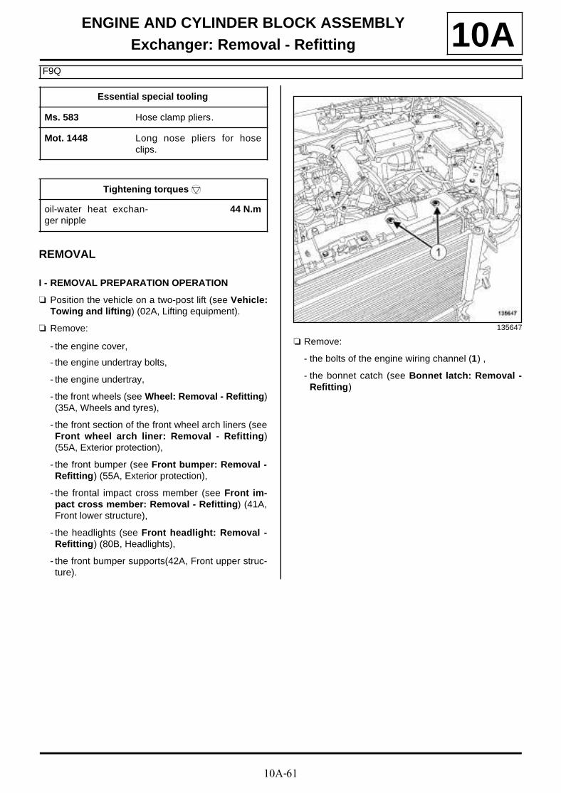
10A-61
ENGINE AND CYLINDER BLOCK ASSEMBLYExchanger: Removal - Refitting
F9Q
10A
REMOVAL
I - REMOVAL PREPARATION OPERATION
a Position the vehicle on a two-post lift (see Vehicle:Towing and lifting) (02A, Lifting equipment).
a Remove:
- the engine cover,
- the engine undertray bolts,
- the engine undertray,
- the front wheels (see Wheel: Removal - Refitting)(35A, Wheels and tyres),
- the front section of the front wheel arch liners (seeFront wheel arch liner: Removal - Refitting)(55A, Exterior protection),
- the front bumper (see Front bumper: Removal -Refitting) (55A, Exterior protection),
- the frontal impact cross member (see Front im-pact cross member: Removal - Refitting) (41A,Front lower structure),
- the headlights (see Front headlight: Removal -Refitting) (80B, Headlights),
- the front bumper supports(42A, Front upper struc-ture).
a Remove:
- the bolts of the engine wiring channel (1) ,
- the bonnet catch (see Bonnet latch: Removal -Refitting)
Essential special tooling
Ms. 583 Hose clamp pliers.
Mot. 1448 Long nose pliers for hoseclips.
Tightening torquesm
oil-water heat exchan-ger nipple
44 N.m
135647

10A-62
ENGINE AND CYLINDER BLOCK ASSEMBLYExchanger: Removal - Refitting
F9Q
10A
a Remove the front end panel bolts (2) .
a Tilt the front panel.
a Remove the intercooler outlet air outlet pipe (see12B, Turbocharging, Intercooler air outlet pipe:Removal - Refitting, page 12B-56) .
a Remove the oil filter (see 10A, Engine and cylinderblock assembly, Oil filter: Removal - Refitting,page 10A-48) .
II - OPERATION FOR REMOVAL OF PART CONCERNED
a Fit the tools (3) (Ms. 583) onto the intercooler ho-ses.
a Separate the clips (4) from the intercooler hosesusing the tool (Mot. 1448).
a Disconnect the intercooler hoses.
135645
135646
136201
136203

10A-63
ENGINE AND CYLINDER BLOCK ASSEMBLYExchanger: Removal - Refitting
F9Q
10A
a Remove:
- the nipple (5) from the oil-water heat exchanger,
- the oil-water heat exchanger,
- the oil-water heat exchanger seal.
REFITTING
I - REFITTING PREPARATION OPERATION
a Use SURFACE CLEANER (see Vehicle: Parts and ingredients for the repairwork) (04B, Consu-mables - Products) to clean and degrease:
- the oil-water heat exchanger seal mating faces if itis to be reused,
- the cylinder block gasket face.
a parts always to be replaced: coolant-engine oilheat exchanger seal on the cylinder block (10,05,05,12).
parts always to be replaced: Intercooler air out-let pipe (10,09,04,03).
II - REFITTING OPERATION FOR PART CONCERNED
a Refit:
- a new seal to the oil-water heat exchanger,
- the oil-water heat exchanger.
a Torque tighten the oil-water heat exchanger nip-ple (44 N.m).
a Connect the oil-water heat exchanger hoses.
a Fit the hose clips on the oil-water heat exchangerusing the tool (Mot. 1448).
a Remove the tools (Ms. 583) from the oil-water heatexchanger hoses.
a Refit the oil filter (see 10A, Engine and cylinderblock assembly, Oil filter: Removal - Refitting,page 10A-48) .
III - FINAL OPERATION
a Refit a new intercooler air outlet pipe (see 12B, Tur-bocharging, Intercooler air outlet pipe: Removal- Refitting, page 12B-56) .
a Fit the front end panel.
a Refit:
- the bonnet catch (see Bonnet latch: Removal -Refitting) (52A, Non-side opening element mecha-nisms),
- the bolts for the engine wiring harness channel,
- the front bumper supports (see Front bumpersupport: Removal - Refitting) (42A, Front upperstructure),
- the headlights (see Front headlight: Removal -Refitting) (80B, Headlights),
- the frontal impact cross member (see Front im-pact cross member: Removal - Refitting) (41A,Front lower structure),
- the front bumper (see Front bumper: Removal -Refitting) (55A, Exterior protection),
- the front section of the front wheel arch liners (seeFront wheel arch liner: Removal - Refitting)(55A, Exterior protection),
- the front wheels (see Wheel: Removal - Refitting)(35A, Wheels and tyres),
- the engine undertray,
- the engine cover.
a Bleed the cooling system (see 19A, Cooling, Coo-ling circuit: Draining - Refilling, page 19A-17) .
136208

10A-64
ENGINE AND CYLINDER BLOCK ASSEMBLYOil pressure sensor: Removal - Refitting
K9K
10A
REMOVAL
I - REMOVAL PREPARATION OPERATION
a Position the vehicle on a two-post lift (see Vehicle:Towing and lifting) (02A, Lifting equipment).
a Remove:
- the engine undertray bolts,
- the engine undertray.
II - OPERATION FOR REMOVAL OF PART CONCERNED
a Disconnect the oil pressure sensor connector (1) .
a Remove the oil pressure sensor using the (Mot.1495).
REFITTING
I - REFITTING PREPARATION OPERATION
a Wipe any oil run-off with a cloth.
II - REFITTING OPERATION FOR PART CONCERNED
a Refit the oil pressure sensor using the (Mot. 1495).
a Connect the oil pressure sensor connector.
III - FINAL OPERATION
a Refit the engine undertray.
Essential special tooling
Mot. 1495 22 mm oxygen sensor remo-val/refitting socket - 1/2"square drive and a 24 mmAllen key.
123835

10A-65
ENGINE AND CYLINDER BLOCK ASSEMBLYOil pressure sensor: Removal - Refitting
K4M
10A
REMOVAL
I - REFITTING PREPARATION OPERATION
a Position the vehicle on a two-post lift (see Vehicle:Towing and lifting) (02A, Lifting equipment).
a Remove the front engine cover.
a Remove:
- the bolt (1) for the alternator strut from the cylinderblock,
- the bolt (2) for the alternator strut from the alterna-tor,
- the alternator strut.
II - OPERATION FOR REMOVAL OF PART CONCERNED
a Disconnect the oil pressure sensor connector.
a Remove the oil pressure sensor (3) .
Tightening torquesm
oil pressure sensor 33 N.m
alternator strut bolt onthe alternator
25 N.m
alternator strut bolt onthe cylinder block
25 Nm
K4M, and 858 or 866
136573
K4M, and 848
135245
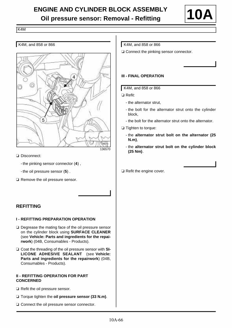
10A-66
ENGINE AND CYLINDER BLOCK ASSEMBLYOil pressure sensor: Removal - Refitting
K4M
10A
a Disconnect:
- the pinking sensor connector (4) ,
- the oil pressure sensor (5) .
a Remove the oil pressure sensor.
REFITTING
I - REFITTING PREPARATION OPERATION
a Degrease the mating face of the oil pressure sensoron the cylinder block using SURFACE CLEANER(see Vehicle: Parts and ingredients for the repai-rwork) (04B, Consumables - Products).
a Coat the threading of the oil pressure sensor with SI-LICONE ADHESIVE SEALANT (see Vehicle:Parts and ingredients for the repairwork) (04B,Consumables - Products).
II - REFITTING OPERATION FOR PART CONCERNED
a Refit the oil pressure sensor.
a Torque tighten the oil pressure sensor (33 N.m).
a Connect the oil pressure sensor connector.
a Connect the pinking sensor connector.
III - FINAL OPERATION
a Refit:
- the alternator strut,
- the bolt for the alternator strut onto the cylinderblock,
- the bolt for the alternator strut onto the alternator.
a Tighten to torque:
- the alternator strut bolt on the alternator (25N.m),
- the alternator strut bolt on the cylinder block(25 Nm).
a Refit the engine cover.
K4M, and 858 or 866
136570
K4M, and 858 or 866
K4M, and 858 or 866
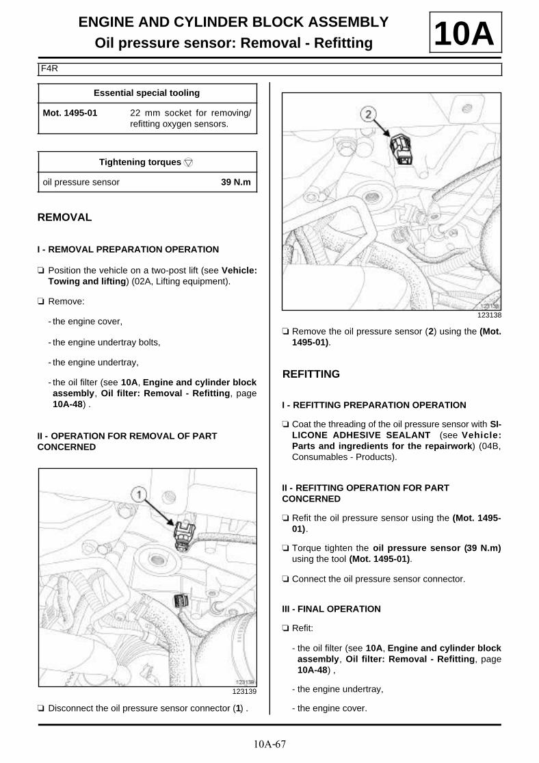
10A-67
ENGINE AND CYLINDER BLOCK ASSEMBLYOil pressure sensor: Removal - Refitting
F4R
10A
REMOVAL
I - REMOVAL PREPARATION OPERATION
a Position the vehicle on a two-post lift (see Vehicle:Towing and lifting) (02A, Lifting equipment).
a Remove:
- the engine cover,
- the engine undertray bolts,
- the engine undertray,
- the oil filter (see 10A, Engine and cylinder blockassembly, Oil filter: Removal - Refitting, page10A-48) .
II - OPERATION FOR REMOVAL OF PART CONCERNED
a Disconnect the oil pressure sensor connector (1) .
a Remove the oil pressure sensor (2) using the (Mot.1495-01).
REFITTING
I - REFITTING PREPARATION OPERATION
a Coat the threading of the oil pressure sensor with SI-LICONE ADHESIVE SEALANT (see Vehicle:Parts and ingredients for the repairwork) (04B,Consumables - Products).
II - REFITTING OPERATION FOR PART CONCERNED
a Refit the oil pressure sensor using the (Mot. 1495-01).
a Torque tighten the oil pressure sensor (39 N.m)using the tool (Mot. 1495-01).
a Connect the oil pressure sensor connector.
III - FINAL OPERATION
a Refit:
- the oil filter (see 10A, Engine and cylinder blockassembly, Oil filter: Removal - Refitting, page10A-48) ,
- the engine undertray,
- the engine cover.
Essential special tooling
Mot. 1495-01 22 mm socket for removing/refitting oxygen sensors.
Tightening torquesm
oil pressure sensor 39 N.m
123139
123138
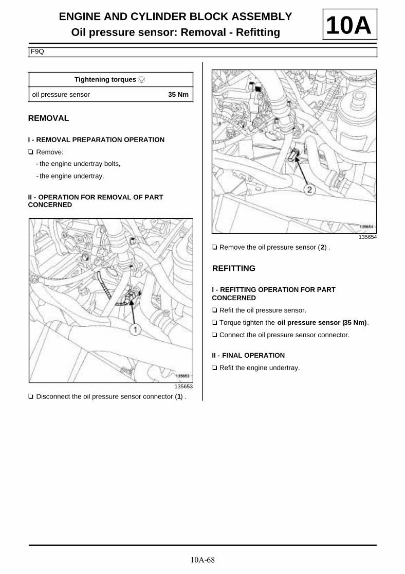
10A-68
ENGINE AND CYLINDER BLOCK ASSEMBLYOil pressure sensor: Removal - Refitting
F9Q
10A
REMOVAL
I - REMOVAL PREPARATION OPERATION
a Remove:
- the engine undertray bolts,
- the engine undertray.
II - OPERATION FOR REMOVAL OF PART CONCERNED
a Disconnect the oil pressure sensor connector (1) .
a Remove the oil pressure sensor (2) .
REFITTING
I - REFITTING OPERATION FOR PART CONCERNED
a Refit the oil pressure sensor.
a Torque tighten the oil pressure sensor (35 Nm).
a Connect the oil pressure sensor connector.
II - FINAL OPERATION
a Refit the engine undertray.
Tightening torquesm
oil pressure sensor 35 Nm
135653
135654

10A-69
ENGINE AND CYLINDER BLOCK ASSEMBLYOil level sensor: Removal - Refitting
K9K
10AREMOVAL
I - REMOVAL PREPARATION OPERATION
a Position the vehicle on a two-post lift (see Vehicle:Towing and lifting) (02A, Lifting equipment).
a Remove:
- the engine undertray bolts,
- the engine undertray.
II - OPERATION FOR REMOVAL OF PART CONCERNED
a Disconnect the connector (1) from the oil level sen-sor.
a Remove the oil level sensor .
REFITTING
I - REFITTING PREPARATION OPERATION
a Wipe any oil run-off with a cloth.
II - REFITTING OPERATION FOR PART CONCERNED
a Refit the oil level sensor.
a Connect the connector to the oil level sensor.
III - FINAL OPERATION
a Refit the engine undertray.
123834
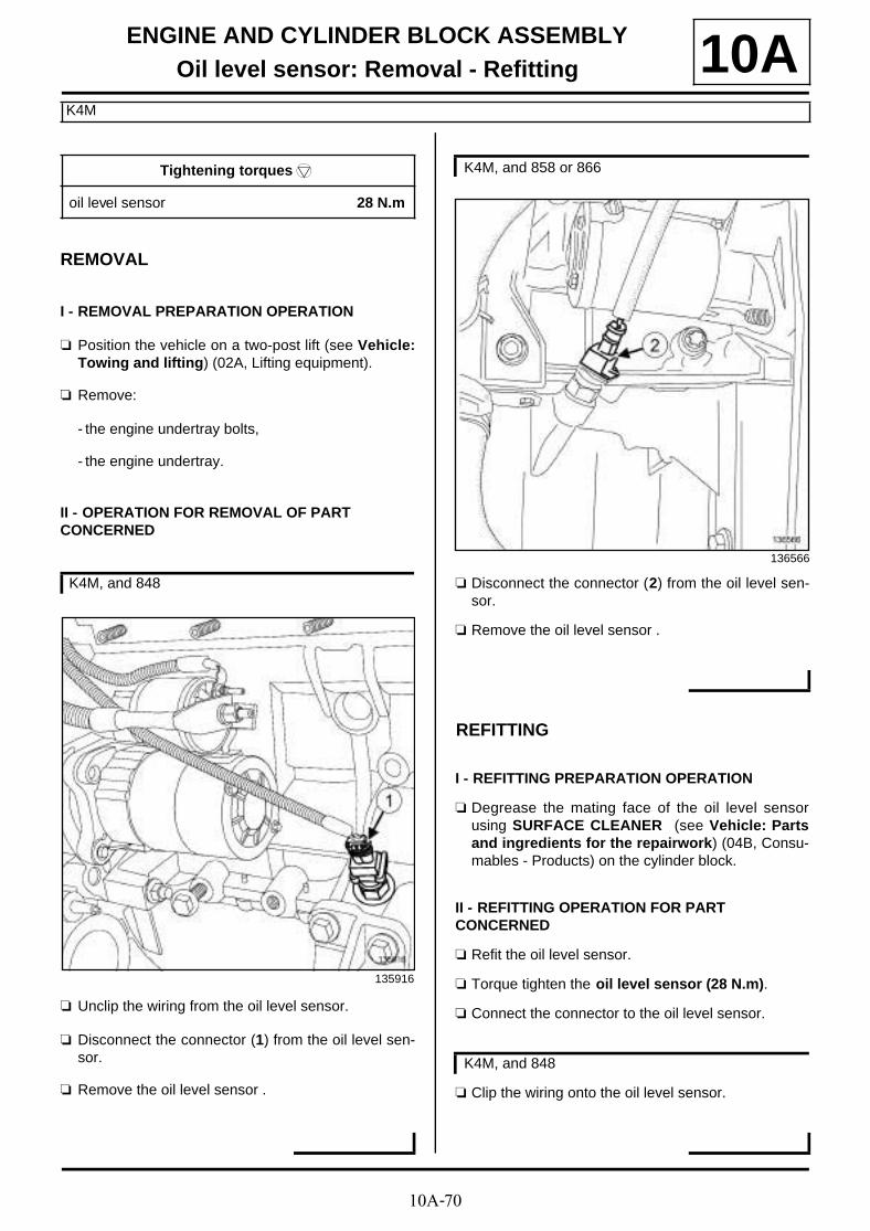
10A-70
ENGINE AND CYLINDER BLOCK ASSEMBLYOil level sensor: Removal - Refitting
K4M
10A
REMOVAL
I - REMOVAL PREPARATION OPERATION
a Position the vehicle on a two-post lift (see Vehicle:Towing and lifting) (02A, Lifting equipment).
a Remove:
- the engine undertray bolts,
- the engine undertray.
II - OPERATION FOR REMOVAL OF PART CONCERNED
a Unclip the wiring from the oil level sensor.
a Disconnect the connector (1) from the oil level sen-sor.
a Remove the oil level sensor .
a Disconnect the connector (2) from the oil level sen-sor.
a Remove the oil level sensor .
REFITTING
I - REFITTING PREPARATION OPERATION
a Degrease the mating face of the oil level sensorusing SURFACE CLEANER (see Vehicle: Partsand ingredients for the repairwork) (04B, Consu-mables - Products) on the cylinder block.
II - REFITTING OPERATION FOR PART CONCERNED
a Refit the oil level sensor.
a Torque tighten the oil level sensor (28 N.m).
a Connect the connector to the oil level sensor.
a Clip the wiring onto the oil level sensor.
Tightening torquesm
oil level sensor 28 N.m
K4M, and 848
135916
K4M, and 858 or 866
136566
K4M, and 848
10A-71
ENGINE AND CYLINDER BLOCK ASSEMBLYOil level sensor: Removal - Refitting
K4M
10AIII - FINAL OPERATION
a Refit the engine undertray.

10A-72
ENGINE AND CYLINDER BLOCK ASSEMBLYOil level sensor: Removal - Refitting
F4R
10A
REMOVAL
I - REMOVAL PREPARATION OPERATION
a Position the vehicle on a two-post lift (see Vehicle:Towing and lifting) (02A, Lifting equipment).
a Remove:
- the engine undertray bolts,
- the engine undertray.
II - OPERATION FOR REMOVAL OF PART CONCERNED
a Disconnect the connector (1) from the oil level sen-sor from underneath.
a Remove the oil level sensor (2) from underneath.
REFITTING
I - REFITTING OPERATION FOR PART CONCERNED
a Refit the oil level sensor.
a Tighten to torque the oil level sensor (25 Nm).
a Connect the connector to the oil level sensor.
II - FINAL OPERATION
a Refit the engine undertray.
Tightening torquesm
oil level sensor 25 Nm
123139
123140

10A-73
ENGINE AND CYLINDER BLOCK ASSEMBLYOil level sensor: Removal - Refitting
F9Q
10A
REMOVAL
I - REMOVAL PREPARATION OPERATION
a Position the vehicle on a two-post lift (see Vehicle:Towing and lifting) (02A, Lifting equipment).
a Remove:
- the engine cover,
- the engine undertray bolts,
- the engine undertray,
- the front wheels (see Wheel: Removal - Refitting)(35A, Wheels and tyres),
- the front section of the front wheel arch liners (seeFront wheel arch liner: Removal - Refitting)(55A, Exterior protection),
- the front bumper (see Front bumper: Removal -Refitting) (55A, Exterior protection),
- the headlights (see Front headlight: Removal -Refitting) (80B, Headlights),
- the frontal impact cross member (see Front im-pact cross member: Removal - Refitting) (41A,Front lower structure),
- the front bumper supports (see Front bumpersupport: Removal - Refitting) (42A, Front upperstructure).
a Remove:
- the bolts (1) of the engine wiring channel,
- the bonnet catch (see Bonnet latch: Removal -Refitting) (52A, Non-side opening element mecha-nisms).
Tightening torquesm
oil level sensor 25 N.m
135647

10A-74
ENGINE AND CYLINDER BLOCK ASSEMBLYOil level sensor: Removal - Refitting
F9Q
10A
a Remove the front end panel bolts (2) .
a Tilt the front end panel.
a Remove the intercooler air outlet pipe (see 12B,Turbocharging, Intercooler air outlet pipe: Re-moval - Refitting, page 12B-56) .
II - OPERATION FOR REMOVAL OF PART CONCERNED
a Disconnect the connector (3) from the oil level sen-sor.
a Remove the oil level sensor (4) .
REFITTING
I - REFITTING OPERATION FOR PART CONCERNED
a Refit the oil level sensor.
135645
135646
136204
136205
10A-75
ENGINE AND CYLINDER BLOCK ASSEMBLYOil level sensor: Removal - Refitting
F9Q
10Aa Tighten to torque the oil level sensor (25 N.m).
II - FINAL OPERATION
a Refit:
- a new intercooler air outlet pipe (see 12B, Turbo-charging, Intercooler air outlet pipe: Removal -Refitting, page 12B-56) ,
- the front panel,
- the bonnet catch (see Bonnet latch: Removal -Refitting) (52A, Non-side opening element mecha-nisms),
- the bolts for the engine wiring harness channel,
- the front bumper supports (see Front bumpersupport: Removal - Refitting) (42A, Front upperstructure),
- the frontal impact cross member (see Front im-pact cross member: Removal - Refitting) (41A,Front lower structure),
- the headlights (see Front headlight: Removal -Refitting) (80B, Headlights),
- the front bumper (see Front bumper: Removal -Refitting) (55A, Exterior protection),
- the front section of the front wheel arch liners (seeFront wheel arch liner: Removal - Refitting)(55A, Exterior protection),
- the front wheels (see Wheel: Removal - Refitting)(35A, Wheels and tyres),
- the engine undertray,
- the engine cover.
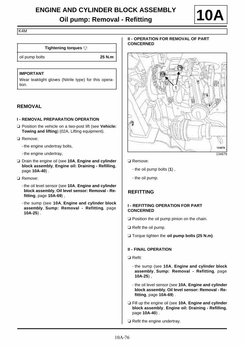
10A-76
ENGINE AND CYLINDER BLOCK ASSEMBLYOil pump: Removal - Refitting
K4M
10A
REMOVAL
I - REMOVAL PREPARATION OPERATION
a Position the vehicle on a two-post lift (see Vehicle:Towing and lifting) (02A, Lifting equipment).
a Remove:
- the engine undertray bolts,
- the engine undertray,
a Drain the engine oil (see 10A, Engine and cylinderblock assembly, Engine oil: Draining - Refilling,page 10A-40) .
a Remove:
- the oil level sensor (see 10A, Engine and cylinderblock assembly, Oil level sensor: Removal - Re-fitting, page 10A-69) ,
- the sump (see 10A, Engine and cylinder blockassembly, Sump: Removal - Refitting, page10A-25) .
II - OPERATION FOR REMOVAL OF PART CONCERNED
a Remove:
- the oil pump bolts (1) ,
- the oil pump.
REFITTING
I - REFITTING OPERATION FOR PART CONCERNED
a Position the oil pump pinion on the chain.
a Refit the oil pump.
a Torque tighten the oil pump bolts (25 N.m).
II - FINAL OPERATION
a Refit:
- the sump (see 10A, Engine and cylinder blockassembly, Sump: Removal - Refitting, page10A-25) ,
- the oil level sensor (see 10A, Engine and cylinderblock assembly, Oil level sensor: Removal - Re-fitting, page 10A-69) .
a Fill up the engine oil (see 10A, Engine and cylinderblock assembly , Engine oil: Draining - Refilling,page 10A-40) .
a Refit the engine undertray.
Tightening torquesm
oil pump bolts 25 N.m
IMPORTANT
Wear leaktight gloves (Nitrile type) for this opera-tion.
134679

10A-77
ENGINE AND CYLINDER BLOCK ASSEMBLYOil pump: Removal - Refitting
F9Q
10A
REMOVAL
I - REMOVAL PREPARATION OPERATION
a Position the vehicle on a two-post lift (see Vehicle:Towing and lifting) (02A, Lifting equipment).
a Remove:
- the engine undertray bolts,
- the engine undertray.
a Drain the engine oil (see 10A, Engine and cylinderblock assembly, Engine oil: Draining - Refilling,page 10A-40) .
a Remove:
- the lower engine tie-bar (see 19D, Engine moun-ting, Lower engine tie-bar: Removal - Refitting,page 19D-33) ,
- the sump (see 10A, Engine and cylinder blockassembly, Sump: Removal - Refitting, page10A-25) .
II - OPERATION FOR REMOVAL OF PART CONCERNED
a Remove:
- the oil splash plate bolt (1) ,
- the oil splash plate,
- the oil pump bolts (2) ,
- the oil pump.
REFITTING
I - REFITTING PREPARATION OPERATION
a Check for centring rings on the cylinder block.
II - REFITTING OPERATION FOR PART CONCERNED
a Position the oil pump pinion on the chain.
a Refit:
- the oil pump,
- the oil splash plate.
a Tighten to torque:
- the oil pump bolts (25 N.m),
- the oil splash plate bolt (25 N.m)
III - FINAL OPERATION
a Refit:
- the sump (see 10A, Engine and cylinder blockassembly, Sump: Removal - Refitting, page10A-25) ,
- the lower engine tie-bar (see 19D, Engine moun-ting, Lower engine tie-bar: Removal - Refitting,page 19D-33) .
a Fill up the engine oil (see 10A, Engine and cylinderblock assembly , Engine oil: Draining - Refilling,page 10A-40) .
a Refit the engine undertray.
Tightening torquesm
oil pump bolts 25 N.m
oil splash plate bolt 25 N.m
23224

10A-78
ENGINE AND CYLINDER BLOCK ASSEMBLYOil pump: Removal - Refitting
K9K
10A
REMOVAL
I - REMOVAL PREPARATION OPERATION
a Position the vehicle on a two-post lift (see Vehicle:Towing and lifting) (02A, Lifting equipment).
a Remove:
- the engine cover,
- the dipstick,
- the engine undertray bolts,
- the engine undertray.
a Drain the engine oil (see 10A, Engine and cylinderblock assembly, Engine oil: Draining - Refilling,page 10A-40) .
a Remove:
- the lower engine tie-bar (see 19D, Engine moun-ting, Lower engine tie-bar: Removal - Refitting,page 19D-33) ,
- the sump (see 10A, Engine and cylinder blockassembly, Sump: Removal - Refitting, page10A-25) .
II - OPERATION FOR REMOVAL OF PART CONCERNED
a Remove:
- the oil pump bolts (1) ,
- the oil pump.
REFITTING
I - REFITTING PREPARATION OPERATION
a Check for oil pump centering rings on the cylinderblock.
II - REFITTING OPERATION FOR PART CONCERNED
a Refit the oil pump.
a Torque tighten the oil pump bolts (25 N.m).
III - FINAL OPERATION
a Refit:
- the sump (see 10A, Engine and cylinder blockassembly, Sump: Removal - Refitting, page10A-25) ,
- the lower engine tie-bar (see 19D, Engine moun-ting, Lower engine tie-bar: Removal - Refitting,page 19D-33) ,
a Fill up the engine oil (see 10A, Engine and cylinderblock assembly , Engine oil: Draining - Refilling,page 10A-40) .
Tightening torquesm
oil pump bolts 25 N.m
IMPORTANT
Wear leaktight gloves (Nitrile type) for this opera-tion.
135004

10A-79
ENGINE AND CYLINDER BLOCK ASSEMBLYOil pump: Removal - Refitting
K9K
10Aa Refit:
- the engine undertray,
- the dipstick,
- the engine cover.

10A-80
ENGINE AND CYLINDER BLOCK ASSEMBLYOil pump: Removal - Refitting
F4R
10A
REMOVAL
I - REMOVAL PREPARATION OPERATION
a Position the vehicle on a two-post lift (see Vehicle:Towing and lifting) (02A, Lifting equipment).
a Remove:
- the engine undertray bolts,
- the engine undertray,
- the lower engine tie-bar (see 19D, Engine moun-ting, Lower engine tie-bar: Removal - Refitting,page 19D-33) .
a Drain the engine oil (see 10A, Engine and cylinderblock assembly, Engine oil: Draining - Refilling,page 10A-40) .
a Remove the sump (see 10A, Engine and cylinderblock assembly, Sump: Removal - Refitting,page 10A-25) .
II - OPERATION FOR REMOVAL OF PART CONCERNED
a Remove:
- the oil splash plate bolt (1) ,
- the oil splash plate.
a Remove:
- the oil pump bolts (2) ,
- the oil pump.
Tightening torquesm
oil pump bolts 25 N.m
oil splash plate bolt 25 Nm
IMPORTANT
Wear leaktight gloves (Nitrile type) for this opera-tion.
135759
135758
10A-81
ENGINE AND CYLINDER BLOCK ASSEMBLYOil pump: Removal - Refitting
F4R
10AREFITTING
I - REFITTING OPERATION FOR PART CONCERNED
a Position the oil pump pinion on the chain.
a Refit the oil pump.
a Torque tighten the oil pump bolts (25 N.m).
a Refit the oil splash plate.
a Torque tighten the oil splash plate bolt (25 Nm).
II - FINAL OPERATION
a Refit:
- the sump (see 10A, Engine and cylinder blockassembly, Sump: Removal - Refitting, page10A-25) ,
- the lower engine tie-bar (see 19D, Engine moun-ting, Lower engine tie-bar: Removal - Refitting,page 19D-33) .
a Fill up the engine oil (see 10A, Engine and cylinderblock assembly, Engine oil: Draining - Refilling,page 10A-40) .
a Refit the engine undertray.
Note:
Ensure that the oil splash plate is correctly posi-tioned.

10A-82
ENGINE AND CYLINDER BLOCK ASSEMBLYOil pressure: Check 10A
I - PARTS AND CONSUMABLES FOR THE REPAIR WORK
a parts always to be replaced: Engine oil sumpdrain plug seal (10,03,01,04).
a parts always to be replaced: Oil filter (10,05,05,03).
a Consumable:
- engine oil (see Engine oil: Specifications) (Tech-nical Note 6013A, 04B, Lubricants).
II - CHECKING
a Position the vehicle on a two-post lift (see Vehicle:Towing and lifting) (02A, Lifting equipment).
a Remove:
- the engine undertray,
- the oil pressure sensor (see 10A, Engine and cy-linder block assembly, Oil pressure sensor: Re-moval - Refitting, page 10A-64) .
a Engine + End pieces:
- F4R: (G) + (C) + (F) ,
- K9K: (G) + (C) + (F) ,
- F9Q: (G) + (C) + (F) ,
- K4M: (G) + (C) + (F) ,
- M4R:+ (F) .
a In place of the oil pressure sensor, fit the (Mot. 836-05) with suitable adapters using the (Mot. 1495-01)or a 22 mm long socket.
a Start the vehicle.
Essential special tooling
Mot. 836-05 Oil pressure gauge kit.
Mot. 1495-01 22 mm socket for removing/refitting oxygen sensors.
WARNING
Always check the oil level using the dipstick.
Do not exceed the maximum level on the dipstick(could destroy the engine).
Correct the engine oil level if necessary before deli-vering the vehicle to the customer.
Note:
When topping up the engine oil, always leave atleast 10 minutes before checking the level with adipstick.
87363
138760

10A-83
ENGINE AND CYLINDER BLOCK ASSEMBLYOil pressure: Check 10A
a Monitor the engine oil pressure as the oil temperatu-re rises (approximately 80˚C or the first time the en-gine cooling fan is activated); it should not be lessthan the pressure at idle speed.
a If the oil pressure is lower than the pressure at idle speed, check that:
- the oil filter is not clogged,
- dirt or swarf is not present in the engine oil,
- the oil pump is in good condition and being correct-ly driven.
a F9Q engine:
- idle speed: 1 bar,
- 3000 rpm : 4.5 to 5.9 bar.
F4R engine:
- idle speed: 0.5 bar,
- 4000 rpm : 2.2 to 4 bar.
K9K engine:
- idle speed: 0.8 bar,
- 4000 rpm : 3.4 to 5.2 bar.
K4M engine:
- idle speed: 0.5 bar,
- 4000 rpm : 3.1 to 4.4 bar.
M4R engine:
- idle speed: 0.8 bar,
- 2000 rpm : 4.5 bar.
a Switch off the engine.
a Remove the (Mot. 836-05) with the end pieces.
a Refit the oil pressure sensor (see 10A, Engine andcylinder block assembly, Oil pressure sensor:Removal - Refitting, page 10A-64) .
a Wipe any oil run-off with a cloth.
a Wait at least 10 minutes.
a Check the oil level using the dipstick.
a Top up the oil level if necessary (see Engine oil:Specifications) (Technical Note 6013A, 04A, Lubri-cants).
a Start the vehicle and check that there are no oilleaks at the oil pressure sensor.

10A-84
ENGINE AND CYLINDER BLOCK ASSEMBLYMultifunction support: Removal - Refitting
K4M
10A
REMOVAL
I - REMOVAL PREPARATION OPERATION
a Position the vehicle on a two-post lift (see Vehicle:Towing and lifting) (02A, Lifting equipment).
a Disconnect the battery (see Battery: Removal - Re-fitting) (80A, Battery).
a Remove the front engine cover.
a Drain the refrigerant circuit using a refrigerant char-ging station (see Coolant circuit Draining - Refil-ling) (62A, Air conditioning).
a Remove:
- the front wheels (see Wheel: Removal - Refitting)(35A, Wheels and tyres),
- the front section of the front wheel arch liners (seeFront wheel arch liner: Removal - Refitting)(55A, Exterior protection).
a Remove:
- the front right-hand wheel (see Wheel: Removal -Refitting) (35A, Wheels and tyres),
- the front section of the front right-hand wheel archliner (see Front wheel arch liner: Removal - Re-fitting) (55A, Exterior protection).
a Remove:
- the engine undertray bolts,
- the engine undertray,
- the accessories belt (see 11A, Top and front ofengine, Accessories belt: Removal - Refitting,page 11A-7) .
a Remove:
- the front bumper (see Front bumper: Removal -Refitting) (55A, Exterior protection),
- the air deflectors,
- the headlights (see Front headlight: Removal -Refitting) (80B, Headlights),
- the front bumper supports (see Front bumpersupport: Removal - Refitting) (42A, Front upperstructure),
- the audible warning (see Horn: Removal - Refit-ting) (82B, Horn),
- the front impact cross member (see Front impactcross member: Removal - Refitting) (41A, Frontlower structure),
- the bonnet catch (see Bonnet latch: Removal -Refitting) (52A, Non-side opening element mecha-nisms),
- the engine wiring channel from the cooling fan as-sembly.
Essential equipment
refrigerant charging station
Tightening torquesm
bolts 2 and 3 of the mul-tifunction support
5 N.m
multifunction supportbolts (initial torque)
5 N.m
bolts 1, 5, 6, 4, 3, 2 ofthe multifunction sup-port
44 N.m
bolt 7 of the multifunc-tion support on thesump
25 N.m
K4M, and 858 or 866
K4M, and 848
K4M, and 858 or 866

10A-85
ENGINE AND CYLINDER BLOCK ASSEMBLYMultifunction support: Removal - Refitting
K4M
10A
a Disconnect the connector (1) from the air temperatu-re sensor on the intake manifold.
a Remove the oil filter (see 10A, Engine and cylinderblock assembly, Oil filter: Removal - Refitting,page 10A-48) .
a Unclip the hoses (2) from the cooling fan assembly.
a Remove:
- the upper bolts (3) from the front end panel,
- the front end panel upper clips (4) .
K4M, and 848
136483
K4M, and 858 or 866
135930
135719

10A-86
ENGINE AND CYLINDER BLOCK ASSEMBLYMultifunction support: Removal - Refitting
K4M
10A
a Remove the lower bolts (5) from the front end panel.
a Move the front end panel aside.
a Remove:
- the alternator (see 16A, Starting - Charging, Al-ternator: Removal - Refitting, page 16A-1) ,
- the air conditioning compressor (see Compressor:Removal - Refitting) (62A, Air conditioning).
II - OPERATION FOR REMOVAL OF PART CONCERNED
a Remove:
- the multifunction support bolts (6) ,
- the multifunction support.
REFITTING
I - REFITTING OPERATION FOR PART CONCERNED
a Refit the multifunction support.
135713
135258
135258

10A-87
ENGINE AND CYLINDER BLOCK ASSEMBLYMultifunction support: Removal - Refitting
K4M
10Aa Pretighten to torque the bolts 2 and 3 of the multi-
function support (5 N.m).
a Loosen bolts 2 and 3 by one half-turn.
a Pretighten to torque and in order the multifunctionsupport bolts (initial torque) (5 N.m).
a Tighten to torque and in order:
- the bolts 1, 5, 6, 4, 3, 2 of the multifunction sup-port (44 N.m),
- the bolt 7 of the multifunction support on thesump (25 N.m).
II - FINAL OPERATION
a Refit:
- the air conditioning compressor (see Compressor:Removal - Refitting) (62A, Air conditioning),
- the alternator (see 16A, Starting - Charging, Al-ternator: Removal - Refitting, page 16A-1) .
a Fit the front end panel.
a Refit:
- the upper bolts on the front end panel,
- the lower bolts on the front end panel.
a Clip on the cooling fan assembly hoses.
a Refit:
- the upper clips on the front end panel,
- the engine wiring channel on the cooling fan as-sembly,
- the bonnet catch (see Bonnet latch: Removal -Refitting) (52A, Non-side opening element mecha-nisms),
- the front impact cross member (see Front impactcross member: Removal - Refitting) (41A, Frontlower structure),
- the audible warning (see Horn: Removal - Refit-ting) (82B, Horn),
- the front bumper supports (see Front bumpersupport: Removal - Refitting) (42A, Front upperstructure),
- the headlights (see Front headlight: Removal -Refitting) (80B, Headlights),
- the air deflectors,
- the front bumper (see Front bumper: Removal -Refitting) (55A, Exterior protection),
a Refit the oil filter (see 10A, Engine and cylinderblock assembly, Oil filter: Removal - Refitting,page 10A-48) .
a Connect the air temperature sensor connector to theintake manifold.
a Top up with engine oil recommended by the manu-facturer (see Engine oil: Specifications) (Techni-cal Note 6013A, 04A, Lubricants).
a Refit:
- the accessories belt (see 11A, Top and front ofengine, Accessories belt: Removal - Refitting,page 11A-7) ,
- the engine undertray.
a Refit:
- the front section of the front wheel arch liners (seeFront wheel arch liner: Removal - Refitting)(55A, Exterior protection),
- the front wheels (see Wheel: Removal - Refitting)(35A, Wheels and tyres).
a Refit:
- the front section of the front right-hand wheel archliner (see Front wheel arch liner: Removal - Re-fitting) (55A, Exterior protection),
- the front right-hand wheel (see Wheel: Removal -Refitting) (35A, Wheels and tyres).
a Connect the battery (see Battery: Removal - Refit-ting) (80A, Battery).
a Fill the refrigerant circuit using a refrigerant char-ging station (see Coolant circuit Draining - Refil-ling) (62A, Air conditioning).
K4M, and 858 or 866
K4M, and 848
K4M, and 858 or 866
K4M, and 848
10A-88
ENGINE AND CYLINDER BLOCK ASSEMBLYMultifunction support: Removal - Refitting
K4M
10Aa Refit the engine cover.

10A-89
ENGINE AND CYLINDER BLOCK ASSEMBLYMultifunction support: Removal - Refitting
K9K
10A
REMOVAL
I - REMOVAL PREPARATION OPERATION
a Position the vehicle on a two-post lift (see Vehicle:Towing and lifting) (02A, Lifting equipment).
a Disconnect the battery (see Battery : Removal -Refitting) (80A, Battery).
a Drain the refrigerant fluid circuit using the refrige-rant charging station (see Coolant circuit Drai-ning - Refilling) (62A, Air conditioning).
a Remove:
- the engine cover,
- the front wheels (see Wheel: Removal - Refitting)(35A, Wheels and tyres),
- the front section of the front wheel arch liners (seeFront wheel arch liner: Removal - Refitting)(55A, Exterior protection),
- the engine undertray bolts,
- the engine undertray,
- the accessories belt (see 11A, Top and front ofengine, Accessories belt: Removal - Refitting,page 11A-7) ,
- the front bumper (see Front bumper: Removal -Refitting) (55A, Exterior protection),
- the turbocharger air outlet pipe (see 12B, Turbo-charging, Intercooler air inlet pipe: Removal -Refitting, page 12B-41) ,
- the headlights (see Front headlight: Removal -Refitting) (80B, Headlights),
- the front bumper supports (see Front bumpersupport: Removal - Refitting) (42A, Front upperstructure),
- the upper air deflector from the cooling radiator,
- the side air deflectors from the cooling radiator,
- the audible warning (see Horn: Removal - Refit-ting) (82B, Horn),
- the frontal impact cross member (see Front im-pact cross member: Removal - Refitting) (41A,Front lower structure),
- the bonnet catch (see Bonnet latch: Removal -Refitting) (52A, Non-side opening element mecha-nisms).
a Unclip the expansion bottle top hose from the frontend panel (1) .
a Remove the engine wiring channel bolts (2) from thefront end panel.
Essential equipment
refrigerant charging station
Tightening torquesm
bolts (1) to (6) of themultifunction support
44 N.m
bolt (7) of the multifunc-tion support
25 N.m
135883
135882
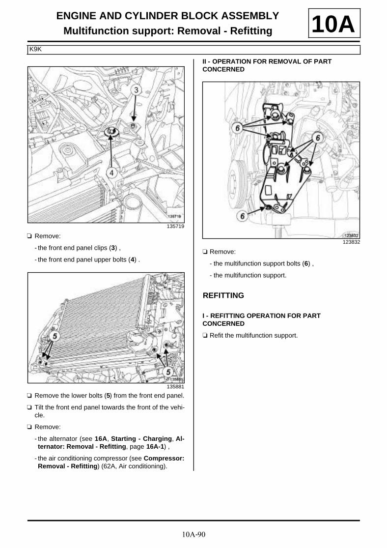
10A-90
ENGINE AND CYLINDER BLOCK ASSEMBLYMultifunction support: Removal - Refitting
K9K
10A
a Remove:
- the front end panel clips (3) ,
- the front end panel upper bolts (4) .
a Remove the lower bolts (5) from the front end panel.
a Tilt the front end panel towards the front of the vehi-cle.
a Remove:
- the alternator (see 16A, Starting - Charging, Al-ternator: Removal - Refitting, page 16A-1) ,
- the air conditioning compressor (see Compressor:Removal - Refitting) (62A, Air conditioning).
II - OPERATION FOR REMOVAL OF PART CONCERNED
a Remove:
- the multifunction support bolts (6) ,
- the multifunction support.
REFITTING
I - REFITTING OPERATION FOR PART CONCERNED
a Refit the multifunction support.
135719
135881
123832

10A-91
ENGINE AND CYLINDER BLOCK ASSEMBLYMultifunction support: Removal - Refitting
K9K
10A
a Tighten to torque and in order:
- the bolts (1) to (6) of the multifunction support(44 N.m),
- the bolt (7) of the multifunction support (25N.m).
II - FINAL OPERATION
a Refit:
- the air conditioning compressor (see Compressor:Removal - Refitting) (62A, Air conditioning),
- the alternator (see 16A, Starting - Charging, Al-ternator: Removal - Refitting, page 16A-1) .
a Fit the front end panel.
a Refit:
- the lower bolts from the front end panel,
- the front end panel upper bolts,
- the front end panel clips,
- the bolts of the engine cooling fan assembly wiringchannel on the front end panel.
a Clip the expansion bottle top hose onto the front endpanel.
a Refit:
- the bonnet catch (see Bonnet latch: Removal -Refitting) (52A, Non-side opening element mecha-nisms),
- the front impact cross member (see Front impactcross member: Removal - Refitting) (41A, Frontlower structure),
- the audible warning (see Horn: Removal - Refit-ting) (82B, Horn),
- the cooling radiator side air deflectors,
- the upper air deflector of the cooling radiator,
- the front bumper supports (see Front bumpersupport: Removal - Refitting) (42A, Front upperstructure).
- the headlights (see Front headlight: Removal -Refitting) (80B, Headlights),
- the turbocharger air outlet pipe (see 12B, Turbo-charging, Intercooler air inlet pipe: Removal -Refitting, page 12B-41) ,
- the front bumper (see Front bumper: Removal -Refitting) (55A, Exterior protection),
- the accessories belt (see 11A, Top and front ofengine, Accessories belt: Removal - Refitting,page 11A-7) ,
- the engine undertray,
- the front section of the front wheel arch liners (seeFront wheel arch liner: Removal - Refitting)(55A, Exterior protection),
- the front wheels (see Wheel: Removal - Refitting)(35A, Wheels and tyres),
- the engine cover.
a Connect the battery (see Battery : Removal - Refit-ting) (80A, Battery).
a Fill the refrigerant circuit using a refrigerant char-ging station (see Coolant circuit Draining - Refil-ling) (62A, Air conditioning).
123832

10A-92
ENGINE AND CYLINDER BLOCK ASSEMBLYMultifunction support: Removal - Refitting
F4R
10A
REMOVAL
I - REMOVAL PREPARATION OPERATION
a Position the vehicle on a two-post lift (see Vehicle:Towing and lifting) (02A, Lifting equipment).
a Drain the refrigerant circuit using a refrigerant char-ging station (see Coolant circuit Draining - Refil-ling) .
a Disconnect the battery (see Battery : Removal -Refitting) (80A, Battery).
a Remove:
- the engine cover,
- the engine undertray bolts,
- the engine undertray,
- the front wheels (see Wheel: Removal - Refitting)(35A, Wheels and tyres),
- the front section of the front wheel arch liners (seeFront wheel arch liner: Removal - Refitting)(55A, Exterior protection),
- the front bumper (see Front bumper: Removal -Refitting) (55A, Exterior protection),
- the upper air deflector,
- the side air deflectors,
- the accessories belt (see 11A, Top and front ofengine, Accessories belt: Removal - Refitting,page 11A-7) ,
- the headlights (see Front headlight: Removal -Refitting) (80B, Headlights),
- the front bumper supports (see Front bumpersupport: Removal - Refitting) (42A, Front upperstructure),
- the audible warning (see Horn: Removal - Refit-ting) (82B, Horn),
- the front impact cross member (see Front impactcross member: Removal - Refitting) (41A, Frontlower structure),
- the bonnet catch (see Bonnet latch: Removal -Refitting) (52A, Non-side opening element mecha-nisms).
a Remove the bolts (2) from the wiring channel of theengine cooling fan assembly.
a Remove:
- the upper bolts (4) from the front end panel,
- the front end panel clips (3) .
Essential equipment
refrigerant charging station
Tightening torquesm
multifunction supportbolts
44 N.m
135736
135719

10A-93
ENGINE AND CYLINDER BLOCK ASSEMBLYMultifunction support: Removal - Refitting
F4R
10A
a Remove the lower bolts (5) from the front end panel.
a Slightly tilt the front end panel towards the front ofthe vehicle.
a Remove:
- the intercooler air inlet pipe (see 12B, Turbochar-ging, Intercooler air inlet pipe: Removal - Refit-ting, page 12B-41) ,
- the alternator (see 16A, Starting - Charging, Al-ternator: Removal - Refitting, page 16A-1) ,
- the air conditioning compressor (see Compressor:Removal - Refitting) (62A, Air conditioning).
II - OPERATION FOR REMOVAL OF PART CONCERNED
a
a Remove:
- the multifunction support bolts (6) ,
- the multifunction support.
REFITTING
I - REFITTING OPERATION FOR PART CONCERNED
a Refit the multifunction support.
a Fit the multifunction support bolts, in the positionsmarked during removal.
a Torque tighten the multifunction support bolts (44N.m).
II - FINAL OPERATION
a Refit:
- the compressor (see Compressor: Removal - Re-fitting) (62A, Air conditioning),
- the alternator (see 16A, Starting - Charging, Al-ternator: Removal - Refitting, page 16A-1) ,
135296
135698
Note:
The multifunction support bolts are not the samelength; mark their positions.
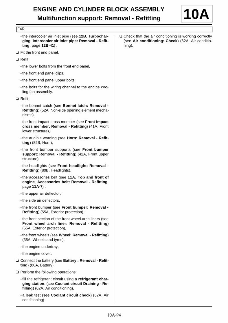
10A-94
ENGINE AND CYLINDER BLOCK ASSEMBLYMultifunction support: Removal - Refitting
F4R
10A- the intercooler air inlet pipe (see 12B, Turbochar-ging, Intercooler air inlet pipe: Removal - Refit-ting, page 12B-41) ,
a Fit the front end panel.
a Refit:
- the lower bolts from the front end panel,
- the front end panel clips,
- the front end panel upper bolts,
- the bolts for the wiring channel to the engine coo-ling fan assembly.
a Refit:
- the bonnet catch (see Bonnet latch: Removal -Refitting) (52A, Non-side opening element mecha-nisms).
- the front impact cross member (see Front impactcross member: Removal - Refitting) (41A, Frontlower structure),
- the audible warning (see Horn: Removal - Refit-ting) (82B, Horn),
- the front bumper supports (see Front bumpersupport: Removal - Refitting) (42A, Front upperstructure),
- the headlights (see Front headlight: Removal -Refitting) (80B, Headlights),
- the accessories belt (see 11A, Top and front ofengine, Accessories belt: Removal - Refitting,page 11A-7) ,
- the upper air deflector,
- the side air deflectors,
- the front bumper (see Front bumper: Removal -Refitting) (55A, Exterior protection),
- the front section of the front wheel arch liners (seeFront wheel arch liner: Removal - Refitting)(55A, Exterior protection),
- the front wheels (see Wheel: Removal - Refitting)(35A, Wheels and tyres),
- the engine undertray,
- the engine cover.
a Connect the battery (see Battery : Removal - Refit-ting) (80A, Battery).
a Perform the following operations:
- fill the refrigerant circuit using a refrigerant char-ging station. (see Coolant circuit Draining - Re-filling) (62A, Air conditioning),
- a leak test (see Coolant circuit check) (62A, Airconditioning).
a Check that the air conditioning is working correctly(see Air conditioning: Check) (62A, Air conditio-ning).

10A-95
ENGINE AND CYLINDER BLOCK ASSEMBLYMultifunction support: Removal - Refitting
F9Q
10A
REMOVAL
I - REMOVAL PREPARATION OPERATION
a Position the vehicle on a two-post lift (see Vehicle:Towing and lifting) (02A, Lifting equipment).
a Disconnect the battery (see Battery : Removal -Refitting) (80A, Battery).
a Drain the refrigerant circuit using a refrigerant char-ging station (see Coolant circuit Draining - Refil-ling) (62A, Air conditioning).
a Remove:
- the engine cover,
- the engine undertray bolts,
- the engine undertray,
- the front wheels (see Wheel: Removal - Refitting)(35A, Wheels and tyres),
- the front section of the front wheel arch liners (seeFront wheel arch liner: Removal - Refitting)(55A, Exterior protection),
- the front bumper (see Front bumper: Removal -Refitting) (55A, Exterior protection),
- the headlights (see Front headlight: Removal -Refitting) (80B, Headlights),
- the frontal impact cross member (see Front im-pact cross member: Removal - Refitting) (41A,Front lower structure),
- the front bumper supports (see Front bumpersupport: Removal - Refitting) (42A, Front upperstructure),
- the accessories belt (see 11A, Top and front ofengine, Accessories belt: Removal - Refitting,page 11A-7) .
a Remove:
- the bolts (1) of the engine wiring channel,
- the bonnet catch (see Bonnet latch: Removal -Refitting) (52A, Non-side opening element mecha-nisms).
Essential equipment
refrigerant charging station
Tightening torquesm
multifunction supportbolts
44 N.m
135647

10A-96
ENGINE AND CYLINDER BLOCK ASSEMBLYMultifunction support: Removal - Refitting
F9Q
10A
a Remove the front end panel bolts (2) .
a Tilt the front end panel.
a Remove:
- the intercooler air outlet pipe (see 12B, Turbo-charging, Intercooler air outlet pipe: Removal -Refitting, page 12B-56) ,
- the alternator (see 16A, Starting - Charging, Al-ternator: Removal - Refitting, page 16A-1) ,
- the compressor (see Compressor: Removal - Re-fitting) (62A, Air conditioning).
II - OPERATION FOR REMOVAL OF PART CONCERNED
a Remove:
- the multifunction support bolts (3) ,
- the multifunction support.
REFITTING
I - REFITTING OPERATION FOR PART CONCERNED
a Refit the multifunction support.
a Torque tighten the multifunction support bolts (44N.m).
II - FINAL OPERATION
a Refit:
- the compressor (see Compressor: Removal - Re-fitting) (62A, Air conditioning),
- the alternator (see 16A, Starting - Charging, Al-ternator: Removal - Refitting, page 16A-1) ,
- the new intercooler air outlet pipe (see 12B, Turbo-charging, Intercooler air outlet pipe: Removal -Refitting, page 12B-56) ,
- the front end panel.
a Refit:
- the bonnet catch (see Bonnet latch: Removal -Refitting) (52A, Non-side opening element mecha-nisms),
135645
135646
137193

10A-97
ENGINE AND CYLINDER BLOCK ASSEMBLYMultifunction support: Removal - Refitting
F9Q
10A- the bolts for the engine wiring harness channel,
- the accessories belt (see 11A, Top and front ofengine, Accessories belt: Removal - Refitting,page 11A-7) ,
- the front bumper supports (see Front bumpersupport: Removal - Refitting) (42A, Front upperstructure),
- the front impact cross member (see Front impactcross member: Removal - Refitting) (41A, Frontlower structure),
- the headlights (see Front headlight: Removal -Refitting) (80B, Headlights),
- the front bumper (see Front bumper: Removal -Refitting) (55A, Exterior protection),
- the front section of the front wheel arch liners (seeFront wheel arch liner: Removal - Refitting)(55A, Exterior protection),
- the front wheels (see Wheel: Removal - Refitting)(35A, Wheels and tyres),
- the engine undertray,
- the engine cover.
a Connect the battery (see Battery : Removal - Refit-ting) (80A, Battery).
a Fill the refrigerant fluid circuit using the refrigerantcharging station (see Coolant circuit Draining -Refilling) (62A, Air conditioning).
.

10A-98
ENGINE AND CYLINDER BLOCK ASSEMBLYEngine/gearbox assembly: Removal - Refitting
K4M
10A
REMOVAL
I - REMOVAL PREPARATION OPERATION
a Position the vehicle on a two-post lift (see Vehicle:Towing and lifting) (02A, Lifting equipment).
a Remove:
- the engine cover,
- the battery (see Battery: Removal - Refitting)(80A, Battery),
- the battery tray (see Battery tray: Removal - Re-fitting) (80A, Battery).
a Loosen the clip on the throttle valve air inlet pipe.
a Disconnect the air outlet pipe from the air filter unit.
a Remove
- the air outlet pipe to the air filter unit,
- the air filter unit (see 12A, Fuel mixture, Air filterunit: Removal - Refitting, page 12A-4) .
Essential special tooling
Ms. 583 Hose clamp pliers.
Mot. 1448 Long nose pliers for hoseclips.
Mot. 1390 Support for removing/refittingthe engine - gearbox assem-bly.
Essential equipment
refrigerant charging station
Tightening torquesm
bolt on the rubber padsupport of the left-handsuspended enginemounting
62 N.m
earth nut on the body 8 N.m
bracket bolt of the con-necting pipe betweenthe « compressor -expansion valve » onthe compressor
8 N.m
battery wiring nuts onthe offset positive termi-nal
8 N.m
connecting pipe bolts onthe condenser
8 N.m
air inlet pipe clip of thethrottle valve
6 N.m
WARNING
In order to avoid any refrigerant leaks, do notdamage (deform, twist, etc.) the pipe.
WARNING
To prevent moisture from entering the system,place plugs on the cold loop components which areopen to the air.
IMPORTANT
Wear protective gloves during the operation.
IMPORTANT
To prevent the vehicle from falling, lash it to thevehicle lift using a strap.

10A-99
ENGINE AND CYLINDER BLOCK ASSEMBLYEngine/gearbox assembly: Removal - Refitting
K4M
10A
a Disconnect the fuel vapour rebreathing pipe (1) fromthe throttle valve.
a Unclip the fuel vapour rebreathing pipe from thethrottle valve.
a Disconnect the vacuum pipe (2) from the throttle val-ve.
a Disconnect the fuel supply pipe (3) from the injectorrail.
a Fit blanking plugs on the fuel supply pipe.
136460 136450
WARNING
To avoid any corrosion or damage, protect theareas on which fuel is likely to run.

10A-100
ENGINE AND CYLINDER BLOCK ASSEMBLYEngine/gearbox assembly: Removal - Refitting
K4M
10A
a Unclip:
- the gear control cables from the manual gearboxby pressing at (A) ,
- the control cables by pushing at (B) .
a Move the gearbox control cables aside.
a Unclip from the manual gearbox controls:
- the anchoring ball joints at (4) ,
- the sleeve stops at (5) .
a Move aside the manual gearbox controls.
K4M, and 848
134553
109149
K4M, and 858 or 866
134484
101743

10A-101
ENGINE AND CYLINDER BLOCK ASSEMBLYEngine/gearbox assembly: Removal - Refitting
K4M
10A
a Place the tool (Ms. 583) between the brake fluid re-servoir and the clutch master cylinder.
a Remove the hydraulic clutch pipe (see Clutch cir-cuit: Removal - Refitting) (37A, Mechanical com-ponent controls).
a Remove:
- the breather pipe onto the gearbox,
- the front wheels (see Wheel: Removal - Refitting)(35A, Wheels and tyres),
- the front section of the front wheel arch liners (seeFront wheel arch liner: Removal - Refitting)(55A, Exterior protection),
- the engine undertray bolts,
- the engine undertray,
- the front bumper (see Front bumper: Removal -Refitting) (55A, Exterior protection).
a Drain:
- the cooling system (see 19A, Cooling, Coolingcircuit: Draining - Refilling, page 19A-17) ,
- the manual gearbox (see Manual gearbox oil:Draining - Refilling) (21A, Manual gearbox).
- the refrigerant circuit using a refrigerant chargingstation (see Coolant circuit Draining - Refilling)(62A, Air conditioning),
- the engine oil if necessary (see 10A, Engine andcylinder block assembly, Engine oil: Draining -Refilling, page 10A-40) .
a Disconnect the reverse gear switch connector.
a Remove:
- the bolts (6) from the exhaust bracket,
- the exhaust flange ring,
- the lower engine tie-bar (see 19D, Engine moun-ting, Lower engine tie-bar: Removal - Refitting,page 19D-33) ,
- the front right-hand wheel driveshaft (see Front ri-ght-hand wheel driveshaft: Removal - Refitting)(29A, Driveshafts),
- the front left-hand wheel driveshaft (see Front left-hand wheel driveshaft: Removal - Refitting)(29A, Driveshafts),
136542
JH3
135949
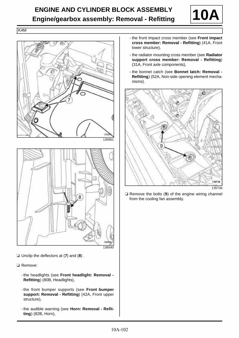
10A-102
ENGINE AND CYLINDER BLOCK ASSEMBLYEngine/gearbox assembly: Removal - Refitting
K4M
10A
a Unclip the deflectors at (7) and (8) .
a Remove:
- the headlights (see Front headlight: Removal -Refitting) (80B, Headlights),
- the front bumper supports (see Front bumpersupport: Removal - Refitting) (42A, Front upperstructure),
- the audible warning (see Horn: Removal - Refit-ting) (82B, Horn),
- the front impact cross member (see Front impactcross member: Removal - Refitting) (41A, Frontlower structure),
- the radiator mounting cross member (see Radiatorsupport cross member: Removal - Refitting)(31A, Front axle components),
- the bonnet catch (see Bonnet latch: Removal -Refitting) (52A, Non-side opening element mecha-nisms).
a Remove the bolts (9) of the engine wiring channelfrom the cooling fan assembly.
135961
136540
135736

10A-103
ENGINE AND CYLINDER BLOCK ASSEMBLYEngine/gearbox assembly: Removal - Refitting
K4M
10A
a Disconnect from the cooling fan assembly:
- the connector (10) ,
- the resistor connector (11) ,
- the relay unit (12) of the front end panel.
a Unclip the cooling fan assembly wiring.
a Move aside the cooling fan assembly wiring.
a Remove using the (Mot. 1448) :
- the top cooling hose clip from the cooling radiator,
- the expansion bottle degassing hose clip from thecooling radiator,
- the bottom cooling hose clip from the cooling radia-tor.
a Disconnect:
- the top cooling hose (13) from the cooling radiator,
- the expansion bottle degassing hose (14) from thecooling radiator,
135482 135954
135951

10A-104
ENGINE AND CYLINDER BLOCK ASSEMBLYEngine/gearbox assembly: Removal - Refitting
K4M
10A- the bottom cooling hose (15) from the cooling ra-diator.

10A-105
ENGINE AND CYLINDER BLOCK ASSEMBLYEngine/gearbox assembly: Removal - Refitting
K4M
10A
a Remove:
- the bolt (16) of the « condenser - expansion valve »connecting pipe bracket,
- the bolt (17) for the « compressor - condenser »connecting pipe bracket.
a Disconnect:
- the « condenser - expansion valve » connectingpipe from the condenser,
- the « compressor - condenser » connecting pipeon the condenser.
a Remove:
- the seal of the « condenser - expansion valve »connecting pipe,
- the seal of the « compressor - condenser » con-necting pipe.
a Insert the blanking plugs.
a Disconnect the pressostat connector from the con-denser.
a Unclip the wiring of the right-hand headlight (18) onthe front end panel.
135952
135955
136537

10A-106
ENGINE AND CYLINDER BLOCK ASSEMBLYEngine/gearbox assembly: Removal - Refitting
K4M
10A
a Remove the bolt (1 9) between the windscreenwasher reservoir and the front end panel.
a Remove:
- the front end panel clips (20) ,
- the front end panel bolts (21) ,
- the front of the vehicle.
a Disconnect the connectors (22) from the offset posi-tive terminal.
a Unclip the offset positive terminal wiring from the off-set positive terminal.
a Remove the battery cable nuts (23) from the offsetpositive terminal.
a Move aside the battery cables.
HEADLIGHT WASHERS WITH BLADE
136535
135719
135508
135507

10A-107
ENGINE AND CYLINDER BLOCK ASSEMBLYEngine/gearbox assembly: Removal - Refitting
K4M
10A
a Unclip the battery wiring channel (24) from the left-hand suspended engine mounting.
a Remove the cover (25) from the Protection and Swit-ching Unit.
a Remove the connectors (26) from the Protection andSwitching Unit.
a Remove:
- the Protection and Switching Unit,
- the engine wiring.
a Remove the air resonator (see 12A, Fuel mixture,Air resonator: Removal - Refitting, page 12A-1) .
a Remove:
- the bolts (27) from the fuse box,
- the fuse box.
a Disconnect:
- the windscreen washer pump connector,
- the windscreen washer pump wiring.
135506
135721
135722
135504

10A-108
ENGINE AND CYLINDER BLOCK ASSEMBLYEngine/gearbox assembly: Removal - Refitting
K4M
10A
a Remove the bolt (28) from the « compressor - ex-pansion valve » connecting pipe bracket.
a Disconnect the « compressor - expansion valve »connecting pipe from the compressor.
a Remove the seal from the « compressor - expansionvalve » connecting pipe.
a Insert the blanking plugs.
a Remove the bolt of the « compressor - condenser »connecting pipe support at (29) .
a Move aside the « compressor - condenser » con-necting pipe.
a Remove:
- the earth nut on the body,
- the earth terminal on the body (30) .
a Disconnect the earth wiring on the body at (31) .
a Remove the fuel vapour absorber connector (32) .
a Disconnect the fuel vapour absorber wiring:
- on the expansion bottle,
- on the body.
a Remove the fuel vapour absorber wiring.
135724
135723
135709
136466

10A-109
ENGINE AND CYLINDER BLOCK ASSEMBLYEngine/gearbox assembly: Removal - Refitting
K4M
10A
a Remove using the (Mot. 1448) :
- the clip (33) of the hose between the heater matrixand the coolant pump inlet pipe,
- the clip (34) of the hose between the heater matrixand the coolant outlet unit,
- the clip (35) of the expansion bottle outlet hose.
a Disconnect:
- the hose between the heater matrix and the coolantpump inlet pipe,
- the hose between the heater matrix and the coolantoutlet unit,
- the expansion bottle outlet hose.
II - OPERATION FOR REMOVAL OF PART CONCERNED
a Mark the positions of the suspended engine moun-tings on the body.
a Support the « engine - gearbox » assembly on theengine marks (36) with the (Mot. 1390).
a Remove the right-hand suspended engine mounting(see 19D, Engine mounting , Right-hand suspen-ded engine mounting: Removal - Refitting, page19D-18) .
135720
135501
136472
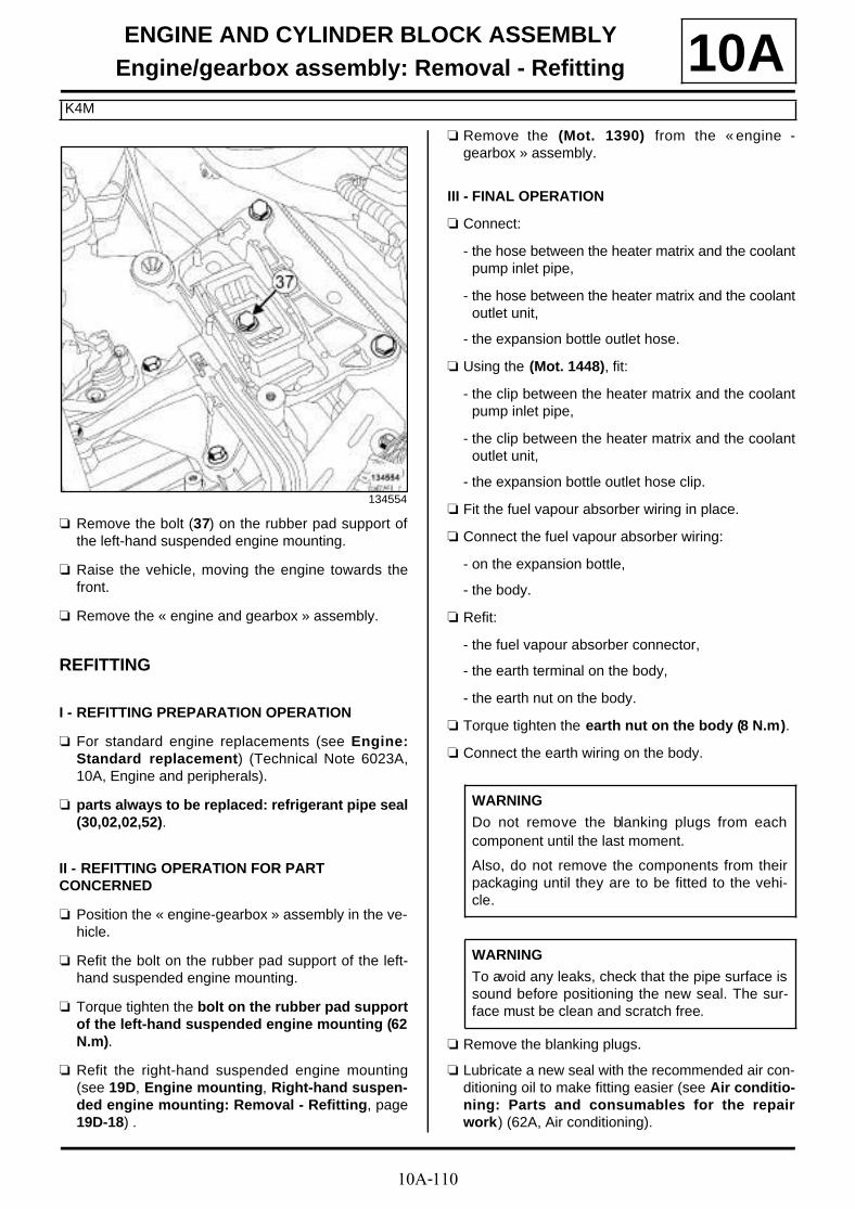
10A-110
ENGINE AND CYLINDER BLOCK ASSEMBLYEngine/gearbox assembly: Removal - Refitting
K4M
10A
a Remove the bolt (37) on the rubber pad support ofthe left-hand suspended engine mounting.
a Raise the vehicle, moving the engine towards thefront.
a Remove the « engine and gearbox » assembly.
REFITTING
I - REFITTING PREPARATION OPERATION
a For standard engine replacements (see Engine:Standard replacement) (Technical Note 6023A,10A, Engine and peripherals).
a parts always to be replaced: refrigerant pipe seal(30,02,02,52).
II - REFITTING OPERATION FOR PART CONCERNED
a Position the « engine-gearbox » assembly in the ve-hicle.
a Refit the bolt on the rubber pad support of the left-hand suspended engine mounting.
a Torque tighten the bolt on the rubber pad supportof the left-hand suspended engine mounting (62N.m).
a Refit the right-hand suspended engine mounting(see 19D, Engine mounting, Right-hand suspen-ded engine mounting: Removal - Refitting, page19D-18) .
a Remove the (Mot. 1390) from the « engine -gearbox » assembly.
III - FINAL OPERATION
a Connect:
- the hose between the heater matrix and the coolantpump inlet pipe,
- the hose between the heater matrix and the coolantoutlet unit,
- the expansion bottle outlet hose.
a Using the (Mot. 1448), fit:
- the clip between the heater matrix and the coolantpump inlet pipe,
- the clip between the heater matrix and the coolantoutlet unit,
- the expansion bottle outlet hose clip.
a Fit the fuel vapour absorber wiring in place.
a Connect the fuel vapour absorber wiring:
- on the expansion bottle,
- the body.
a Refit:
- the fuel vapour absorber connector,
- the earth terminal on the body,
- the earth nut on the body.
a Torque tighten the earth nut on the body (8 N.m).
a Connect the earth wiring on the body.
a Remove the blanking plugs.
a Lubricate a new seal with the recommended air con-ditioning oil to make fitting easier (see Air conditio-ning: Parts and consumables for the repairwork) (62A, Air conditioning).
134554
WARNING
Do not remove the blanking plugs from eachcomponent until the last moment.
Also, do not remove the components from theirpackaging until they are to be fitted to the vehi-cle.
WARNING
To avoid any leaks, check that the pipe surface issound before positioning the new seal. The sur-face must be clean and scratch free.

10A-111
ENGINE AND CYLINDER BLOCK ASSEMBLYEngine/gearbox assembly: Removal - Refitting
K4M
10Aa Fit a new seal on the « compressor - expansion
valve » connecting pipe.
a Couple the « compressor - expansion valve » con-necting pipe on the compressor.
a Refit the bolt of the « compressor - expansionvalve » connecting pipe bracket.
a Torque tighten the bracket bolt of the connectingpipe between the « compressor - expansionvalve » on the compressor (8 N.m).
a Fit the « compressor - condenser » connecting pipe.
a Refit the « compressor - condenser » connectingpipe support.
a Connect:
- the windscreen washer pump connector,
- the wiring.
a Refit:
- the fuse box,
- the air resonator (see 12A, Fuel mixture, Air reso-nator: Removal - Refitting, page 12A-1) .
a Fit:
- the engine wiring,
- the Protection and Switching Unit.
a Refit:
- the Protection and Switching Unit connectors,
- the Protection and Switching Unit,
- the Protection and Switching Unit cover.
a Clip on the battery wiring channel.
a Position the battery cables.
a Torque tighten the battery wiring nuts on the off-set positive terminal (8 N.m).
a Clip the offset positive terminal wiring onto the offsetpositive terminal.
a Connect the connectors to the offset positive termi-nal.
a Refit:
- the front panel,
- the front end panel bolts,
- the front end panel clips.
a Clip the wiring of the right-hand headlight on thefront end panel.
a Refit the bolt between the windscreen washer reser-voir and the front end panel.
a Connect the pressure switch connector to the con-denser.
a Remove the blanking plugs.
a Lubricate the new seals with the recommended airconditioning oil to make fitting easier (see Air condi-tioning: Parts and consumables for the repairwork) (62A, Air conditioning).
a Fit:
- a new seal on the « condenser - expansion valve »connecting pipe,
- a new seal on the « compressor - condenser » con-necting pipe.
a Connect:
- the « condenser - expansion valve » connectingpipe on the condenser,
- the « compressor - condenser » connecting pipeon the condenser.
a Refit:
- the « condenser - expansion valve » connectingpipe bracket bolt,
- the « compressor - condenser » connecting pipebracket bolt.
a Torque tighten the connecting pipe bolts on thecondenser (8 N.m).
a Connect:
- the top cooling hose on the cooling radiator,
- the expansion bottle degassing hose on the coolingradiator,
- the bottom cooling hose on the cooling radiator.
a Using the (Mot. 1448), fit:
- the top cooling hose clip on the cooling radiator,
- the expansion bottle degassing hose clip on thecooling radiator,
- the bottom cooling hose clip on the cooling radia-tor.
a Fit the cooling fan assembly wiring.
a Clip the cooling fan assembly wiring.
HEADLIGHT WASHERS WITH BLADE

10A-112
ENGINE AND CYLINDER BLOCK ASSEMBLYEngine/gearbox assembly: Removal - Refitting
K4M
10Aa Connect:
- the cooling fan assembly connector,
- the cooling fan assembly resistor connector,
- the relay unit on the front end panel.
a Refit:
- the engine wiring channel on the cooling fan as-sembly,
- the bonnet catch (see Bonnet latch: Removal -Refitting) (52A, Non-side opening element mecha-nisms),
- the radiator mounting cross member (see Radiatorsupport cross member: Removal - Refitting)(31A, Front axle components),
- the front impact cross member (see Front impactcross member: Removal - Refitting) (41A, Frontlower structure),
- the audible warning (see Horn: Removal - Refit-ting) (82B, Horn),
- the front bumper supports (see Front bumpersupport: Removal - Refitting) (42A, Front upperstructure),
- the headlights (see Front headlight: Removal -Refitting) (80B, Headlights),
- the air deflectors,
- the front left-hand wheel driveshaft (see Front left-hand wheel driveshaft: Removal - Refitting)(29A, Driveshafts),
- the front right-hand wheel driveshaft (see Front ri-ght-hand wheel driveshaft: Removal - Refitting)(29A, Driveshafts),
- the lower engine tie-bar (see 19D, Engine moun-ting, Lower engine tie-bar: Removal - Refitting,page 19D-33) .
a Connect the reverse gear switch connector.
a Refit:
- the front bumper (see Front bumper: Removal -Refitting) (55A, Exterior protection),
- the engine undertray,
- the front section of the front wheel arch liners (seeFront wheel arch liner: Removal - Refitting)(55A, Exterior protection),
- the front wheels (see Wheel: Removal - Refitting)(35A, Wheels and tyres),
- the breather pipe on the gearbox.
a Refit the hydraulic clutch pipe (see Clutch circuit:Removal - Refitting) (37A, Mechanical componentcontrols).
a Remove the tool (Ms. 583) between the brake fluidreservoir and the clutch master cylinder.
a Bleed the clutch (see Clutch circuit: Bleeding)(37A, Mechanical component controls).
a Clip on the gearbox control cables.
a Adjust the mechanical gearbox control cables (seeMechanical gear control cable: Adjustment)(37A, Mechanical component controls).
a Remove the blanking plugs on the fuel supply pipe.
a Connect:
- the fuel supply pipe to the injector rail,
- the fuel vapour rebreathing pipe on the throttle val-ve.
a Clip the fuel vapour rebreathing pipe onto the throttlevalve.
a Connect the vacuum pipe to the throttle valve.
a Refit the air outlet pipe onto the air filter unit.
a Connect the air outlet pipe of the air filter unit.
a Torque tighten the air inlet pipe clip of the throttlevalve (6 N.m).
a Refit:
- the battery tray (see Battery tray: Removal - Re-fitting) (80A, Battery),
- the battery (see Battery: Removal - Refitting)(80A, Battery).
a Refill:
- the cooling circuit (see 19A, Cooling, Cooling cir-cuit: Draining - Refilling, page 19A-17) ,
- the manual gearbox (see Manual gearbox oil:Draining - Refilling) (21A, Manual gearbox),
- the refrigerant circuit using a refrigerant chargingstation (see Coolant circuit Draining - Refilling)(62A, Air conditioning),
- the engine oil if necessary (see 10A, Engine andcylinder block assembly, Engine oil: Draining -Refilling, page 10A-40) .
a Refit the engine cover.
K4M, and JH3

10A-113
ENGINE AND CYLINDER BLOCK ASSEMBLYEngine/gearbox assembly: Removal - Refitting
K9K, and 830 or 832
10A
Essential special tooling
Mot. 1448 Long nose pliers for hoseclips.
Mot. 1202-02 Pliers for small hose clips.
Ms. 583 Hose clamp pliers.
Mot. 1390 Support for removing/refittingthe engine - gearbox assem-bly.
Mot. 1453 Multiple-adjusting enginemounting support with retai-ning straps.
Mot. 1453-01 Additional winder nut onengine lift support Mot. 1453.
Essential equipment
refrigerant charging station
safety strap(s)
Tightening torquesm
bolt of the left-hand sus-pended engine moun-ting support on thegearbox
62 N.m
bolts of the "rubber pad- cover" assembly of theright-hand suspendedengine mounting on thecylinder head
62 N.m
bolts of the "rubber pad- cover" assembly of theright-hand suspendedengine mounting on thebody
62 N.m
upper engine tie-bar bolton the engine
115 N.m
upper engine tie-bar bolton the body
105 N.m
bolt of the "dehydratorreservoir - compressor"connecting pipe on thecompressor
8 N.m
earth cable nut on thebody
8 N.m
connecting pipe bolts onthe condenser
8 N.m
air filter unit air outletpipe clip on the turbo-charger
5.5 N.m
lower engine tie-bar bolton the subframe
180 N.m
lower engine tie-bar bolton the lower engine tie-bar support
180 N.m
IMPORTANT
Wear leaktight gloves (Nitrile type) for this opera-tion.
WARNING
To prevent impurities from entering the circuit, placeprotective plugs on all fuel circuit componentsexposed to the open air.
WARNING
To avoid any corrosion or damage, protect theareas on which fuel is likely to run.
WARNING
Keep the pipe unions away from contaminatedareas.
WARNING
To prevent moisture from entering the system,place plugs on the cold loop components which areopen to the air.
WARNING
To avoid any leaks, check that the pipe surface issound before positioning the new seal. The surfacemust be clean and scratch free.
Tightening torquesm

10A-114
ENGINE AND CYLINDER BLOCK ASSEMBLYEngine/gearbox assembly: Removal - Refitting
K9K, and 830 or 832
10A
REMOVAL
I - REMOVAL PREPARATION OPERATION
a Position the vehicle on a two-post lift (see Vehicle:Towing and lifting) (02A, Lifting equipment).
a Remove:
- the engine cover,
- the battery (see Battery : Removal - Refitting)(80A, Battery),
- the front wheels (see Wheel: Removal - Refitting)(35A, Wheels and tyres),
- the front section of the front wheel arch liners (seeFront wheel arch liner: Removal - Refitting)(55A, Exterior protection),
- the front bumper (see Front bumper: Removal -Refitting) (55A, Exterior protection),
- the engine undertray bolts,
- the engine undertray.
a Drain:
- the refrigerant circuit using a refrigerant chargingstation (see Coolant circuit Draining - Refilling)(62A, Air conditioning),
- the manual gearbox (see Manual gearbox oil:Draining - Refilling) (21A, Manual gearbox).
- the cooling system (see 19A, Cooling, Coolingcircuit: Draining - Refilling, page 19A-17) ,
- the engine oil (if necessary) (see 10A, Engine andcylinder block assembly, Engine oil: Draining -Refilling, page 10A-40) .
a Remove:
- the front right-hand wheel driveshaft (see Front ri-ght-hand wheel driveshaft: Removal - Refitting)(29A, Driveshafts),
- the front left-hand wheel driveshaft (see Front left-hand wheel driveshaft: Removal - Refitting)(29A, Driveshafts),
- the differential output seals (see Differential out-put seal: Removal - Refitting) (21A, Manual gear-box).
a Remove:
- the bolts (1) from the lower engine tie-bar,
- the lower engine tie-bar.
a Remove the lower engine tie-bar (see 19D, Enginemounting, Lower engine tie-bar: Removal - Refit-ting, page 19D-33) .
WARNING
In order to avoid any refrigerant leaks, do notdamage (deform, twist, etc.) the pipe.
IMPORTANT
To avoid all risk of damage to the systems, applythe safety and cleanliness instructions and ope-ration recommendations before carrying out anyrepair (see Air conditioning: Precautions forrepair) .
K9K, and 832
134223
K9K, and 830
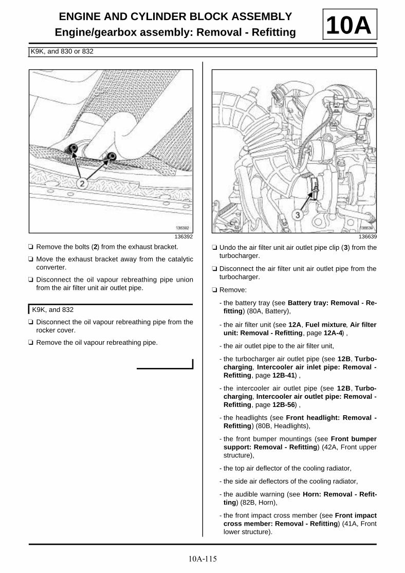
10A-115
ENGINE AND CYLINDER BLOCK ASSEMBLYEngine/gearbox assembly: Removal - Refitting
K9K, and 830 or 832
10A
a Remove the bolts (2) from the exhaust bracket.
a Move the exhaust bracket away from the catalyticconverter.
a Disconnect the oil vapour rebreathing pipe unionfrom the air filter unit air outlet pipe.
a Disconnect the oil vapour rebreathing pipe from therocker cover.
a Remove the oil vapour rebreathing pipe.
a Undo the air filter unit air outlet pipe clip (3) from theturbocharger.
a Disconnect the air filter unit air outlet pipe from theturbocharger.
a Remove:
- the battery tray (see Battery tray: Removal - Re-fitting) (80A, Battery),
- the air filter unit (see 12A, Fuel mixture, Air filterunit: Removal - Refitting, page 12A-4) ,
- the air outlet pipe to the air filter unit,
- the turbocharger air outlet pipe (see 12B, Turbo-charging, Intercooler air inlet pipe: Removal -Refitting, page 12B-41) ,
- the intercooler air outlet pipe (see 12B, Turbo-charging, Intercooler air outlet pipe: Removal -Refitting, page 12B-56) ,
- the headlights (see Front headlight: Removal -Refitting) (80B, Headlights),
- the front bumper mountings (see Front bumpersupport: Removal - Refitting) (42A, Front upperstructure),
- the top air deflector of the cooling radiator,
- the side air deflectors of the cooling radiator,
- the audible warning (see Horn: Removal - Refit-ting) (82B, Horn),
- the front impact cross member (see Front impactcross member: Removal - Refitting) (41A, Frontlower structure).
136392
K9K, and 832
136639

10A-116
ENGINE AND CYLINDER BLOCK ASSEMBLYEngine/gearbox assembly: Removal - Refitting
K9K, and 830 or 832
10A
a Disconnect the connector (4) from the refrigerant cir-cuit pressure sensor.
a Unclip:
- the refrigerant circuit pressure sensor wiring fromthe "condenser - evaporator" connecting pipe at (5),
- the refrigerant circuit pressure sensor wiring fromthe front end panel at (6) .
a Remove:
- the bolt (7) of the "compressor - condenser" con-necting pipe bracket from the body,
- the bolt (8) of the « condenser - expansion valve »connecting pipe bracket,
- the bolt (9) for the « compressor - condenser »connecting pipe bracket.
a Disconnect:
- the « condenser - expansion valve » connectingpipe from the condenser,
- the « compressor - condenser » connecting pipeon the condenser.
a Remove:
- the seal of the « condenser - expansion valve »connecting pipe,
- the seal of the « compressor - condenser » con-necting pipe.
a Insert the blanking plugs.
a Separate the cooling radiator bottom cooling hoseclip (10) on the cooling radiator using the tool (Mot.1448).
a Disconnect the cooling radiator bottom cooling hosefrom the cooling radiator.
a Separate from the cooling radiator:
- the expansion bottle top cooling hose clip (Mot.1202-02) using the tool (11) ,
- the top cooling hose clip (12) using the tool (Mot.1448).
135512 135951
135954

10A-117
ENGINE AND CYLINDER BLOCK ASSEMBLYEngine/gearbox assembly: Removal - Refitting
K9K, and 830 or 832
10Aa Disconnect from the cooling radiator:
- the expansion bottle top cooling hose,
- the cooling radiator top cooling hose.
a Remove the bonnet catch (see Bonnet latch: Re-moval - Refitting) (52A, Non-side opening elementmechanisms).
a Unclip from the front end panel:
- the wiring of the front impact cross member at (13) ,
- the expansion bottle top cooling hose.
a Remove the bolts (14) of the fan assembly wiringchannel from the front end panel.
a Remove from the front end panel:
- the clips (15) ,
- the upper bolts (16) .
a Remove the lower bolts (17) from the front end pa-nel.
135511
135882
135719
135881

10A-118
ENGINE AND CYLINDER BLOCK ASSEMBLYEngine/gearbox assembly: Removal - Refitting
K9K, and 830 or 832
10A
a Disconnect:
- the fan assembly connector (18) ,
- the fan assembly resistor connector (21) .
a Unclip:
- the fan assembly wiring from the fan assembly at(19) ,
- the relay unit (20) from the front end panel.
a Move the fan assembly wiring away from the frontend panel.
a Tilt the front end panel towards the vehicle front (1) .
a Remove the front end panel by pulling it upwards (2).
a Disconnect the connector (22) from the turbochar-ging pressure regulation solenoid valve.
a Disconnect the connectors (23) from the battery dis-connection unit.
a Unclip the battery disconnection unit wiring from theoffset positive terminal.
135482 135510
135508

10A-119
ENGINE AND CYLINDER BLOCK ASSEMBLYEngine/gearbox assembly: Removal - Refitting
K9K, and 830 or 832
10A
a Remove the power cable nuts (24) from the batterydisconnection unit.
a Move aside the power cables.
a Unclip the power wiring channel (25) from the left-hand suspended engine mounting.
a Remove the air resonator (see 12A, Fuel mixture,Air resonator: Removal - Refitting, page 12A-1) .
a Remove the air resonator support nuts (26) .
a Move aside the air resonator support.
a Disconnect the pre-postheating unit connector (27) .
a Remove the earth cable nut (28) from the body.
a Move the earth cable away from the body.
135507
135506
K9K, and 830
136669
135505

10A-120
ENGINE AND CYLINDER BLOCK ASSEMBLYEngine/gearbox assembly: Removal - Refitting
K9K, and 830 or 832
10A
a Remove the Protection and Switching Unit cover(29) .
a Disconnect the connectors (30) from the Protectionand Switching Unit.
a Remove:
- the bolt (31) from the engine fuse box,
- the nuts (32) from the engine fuse box.
a Move aside the engine fuse box.
a Disconnect the diesel heater connector (33) .
a Unclip:
- the diesel heater wiring from the body at (34) ,
- the diesel heater wiring from the "condenser - eva-porator" connecting pipe at (35) ,
135721
135722
135504
135503

10A-121
ENGINE AND CYLINDER BLOCK ASSEMBLYEngine/gearbox assembly: Removal - Refitting
K9K, and 830 or 832
10A- the diesel heater wiring from the radiator mountingcross member.
a Move aside the diesel heater wiring.
a Disconnect the brake servo pipe union (36) from thevacuum pump.
a Unclip the manual gear selector cables (37) by:
- pinching the manual gear selector (A) ,
- pulling the manual gear selector pin (B) ,
- lifting the manual gear selector (C) from the manualgear selector mounting.
a Move aside the manual gear selector cables.
134490
K9K, and 832
134484
101743

10A-122
ENGINE AND CYLINDER BLOCK ASSEMBLYEngine/gearbox assembly: Removal - Refitting
K9K, and 830 or 832
10A
a Unclip the manual gear selector cables by:
- unclipping the anchoring ball joints (38) of the ma-nual gear selector,
- pinching the manual gear selector at (A) ,
- lifting the manual gear selector (39) from the ma-nual gear selector mounting.
a Move aside the manual gear selector cables.
a Fit the tool (Ms. 583) (40) onto the clutch master cy-linder supply pipe.
a Disconnect the clutch pipe from the clutch mastercylinder by pulling on the clip (41) .
a Fit an appropriate blanking plug:
- on the opening of the clutch pipe,
- on the opening of the clutch master cylinder.
K9K, and 830
135416
109149
134486

10A-123
ENGINE AND CYLINDER BLOCK ASSEMBLYEngine/gearbox assembly: Removal - Refitting
K9K, and 830 or 832
10A
a Remove the bolt (42) of the "dehydrator reservoir -compressor" connecting pipe from the compressor.
a Uncouple the "dehydrator reservoir - compressor"connecting pipe from the compressor.
a Remove the seal of the "dehydrator reservoir - com-pressor" connecting pipe on the compressor side.
a Fit an appropriate blanking plug:
- on the compressor opening,
- on the opening of the "dehydrator reservoir - com-pressor" connecting pipe.
a Separate the expansion bottle bottom cooling hoseclip (43) on the expansion bottle.
a Disconnect the expansion bottle bottom coolinghose from the expansion bottle.
a Unclip the expansion bottle bottom cooling hosefrom the high pressure pump protector.
135509 135501
K9K, and 832

10A-124
ENGINE AND CYLINDER BLOCK ASSEMBLYEngine/gearbox assembly: Removal - Refitting
K9K, and 830 or 832
10A
a Separate the clip (44) of each heater matrix coolinghose on the heater matrix (45) .
a Disconnect the heater matrix cooling hoses (45)from the heater matrix.
a Unclip the fuel supply pipe from the "rubber pad - co-ver" assembly of the right-hand suspended enginemounting.
a Disconnect the fuel supply pipe (46) from the highpressure pump.
a Fit an appropriate blanking plug:
- on the fuel supply pipe union,
- on the high pressure pump opening.
a Unclip the diesel return pipe from the "rubber pad -cover" assembly of the right-hand suspended engi-ne mounting.
a Disconnect the diesel return pipe (47) from the die-sel injector return rail.
a Fit an appropriate blanking plug:
- on the diesel return pipe union,
- on the opening of the fuel return rail.
135499
K9K, and 832
134494

10A-125
ENGINE AND CYLINDER BLOCK ASSEMBLYEngine/gearbox assembly: Removal - Refitting
K9K, and 830 or 832
10A
a Unclip the fuel return union (48) of the high pressurepump from the high pressure pump protector.
a Remove:
- the bolt (49) of the high pressure pump protector,
- the high pressure pump protector.
a Unclip the fuel supply pipe from the "rubber pad - co-ver" assembly of the right-hand suspended enginemounting.
a Disconnect the fuel supply pipe (50) from the highpressure pump.
a Fit suitable blanking plugs on:
- on the fuel supply pipe union,
- on the high pressure pump opening.
a Unclip the diesel return pipe from the "rubber pad -cover" assembly of the right-hand suspended engi-ne mounting.
a Disconnect the diesel return pipe (48) from the fuelreturn union of the high pressure pump.
a Fit an appropriate blanking plug:
- on the fuel return pipe union,
- on the opening of the diesel return pipe union of thehigh pressure pump.
a Remove the radiator mounting cross member (seeRadiator support cross member: Removal - Re-fitting) (31A, Front axle components).
II - OPERATION FOR REMOVAL OF PART CONCERNED
a Position the tool (Mot. 1390) under the "engine -gearbox" assembly.
K9K, and 830
135873
135872
17765

10A-126
ENGINE AND CYLINDER BLOCK ASSEMBLYEngine/gearbox assembly: Removal - Refitting
K9K, and 830 or 832
10A
a Remove:
- the upper engine tie-bar bolts (51) ,
- the upper engine tie-bar.
a Remove the bolts (52) of the "rubber pad - cover" as-sembly of the right-hand suspended engine moun-ting from the body.
a Remove the bolts (52) of the "rubber pad - cover" as-sembly of the right-hand suspended engine moun-ting from the body.
a Raise the engine slightly using the tool (Mot. 1453)equipped with the tool (Mot. 1453-01) until the "rub-ber pad - cover" assembly of the right-hand suspen-ded engine mounting detaches from the body.
a Remove:
- the bolts (53) of the "rubber pad - cover" assemblyof the right-hand suspended engine mounting fromthe cylinder head,
- the "rubber pad - cover" assembly of the right-handsuspended engine mounting.
K9K, and 832
134221
134495
K9K, and 830
135411

10A-127
ENGINE AND CYLINDER BLOCK ASSEMBLYEngine/gearbox assembly: Removal - Refitting
K9K, and 830 or 832
10A
a Remove the bolt (54) from the left-hand suspendedengine mounting support on the gearbox.
a Remove the bolt (55) from the left-hand suspendedengine mounting support on the gearbox.
a Remove the "engine - gearbox" assembly using thetool (Mot. 1390).
a Strap the "engine - gearbox" assembly to the tool(Mot. 1390) using a safety strap(s).
REFITTING
I - REFITTING PREPARATION OPERATION
a parts always to be replaced: seal between cata-lytic converter and exhaust downpipe hose (10,08,02,21).
a parts always to be replaced: refrigerant pipe seal(30,02,02,52).
II - REFITTING OPERATION FOR PART CONCERNED
a Position the "engine - gearbox" assembly in the en-gine compartment.
a Torque tighten the bolt of the left-hand suspendedengine mounting support on the gearbox (62N.m).
a Refit the "rubber pad - cover" assembly of the right-hand suspended engine mounting.
K9K, and 832
134485
K9K, and 830
135849
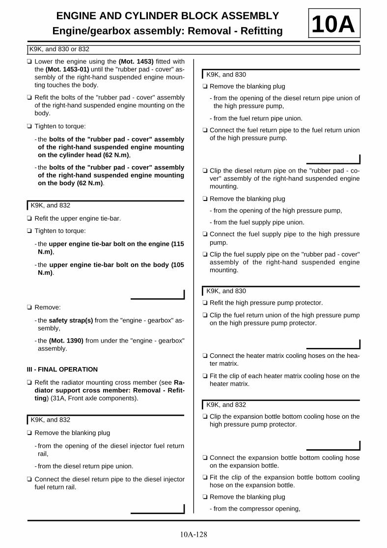
10A-128
ENGINE AND CYLINDER BLOCK ASSEMBLYEngine/gearbox assembly: Removal - Refitting
K9K, and 830 or 832
10Aa Lower the engine using the (Mot. 1453) fitted with
the (Mot. 1453-01) until the "rubber pad - cover" as-sembly of the right-hand suspended engine moun-ting touches the body.
a Refit the bolts of the "rubber pad - cover" assemblyof the right-hand suspended engine mounting on thebody.
a Tighten to torque:
- the bolts of the "rubber pad - cover" assemblyof the right-hand suspended engine mountingon the cylinder head (62 N.m),
- the bolts of the "rubber pad - cover" assemblyof the right-hand suspended engine mountingon the body (62 N.m).
a Refit the upper engine tie-bar.
a Tighten to torque:
- the upper engine tie-bar bolt on the engine (115N.m),
- the upper engine tie-bar bolt on the body (105N.m).
a Remove:
- the safety strap(s) from the "engine - gearbox" as-sembly,
- the (Mot. 1390) from under the "engine - gearbox"assembly.
III - FINAL OPERATION
a Refit the radiator mounting cross member (see Ra-diator support cross member: Removal - Refit-ting) (31A, Front axle components).
a Remove the blanking plug
- from the opening of the diesel injector fuel returnrail,
- from the diesel return pipe union.
a Connect the diesel return pipe to the diesel injectorfuel return rail.
a Remove the blanking plug
- from the opening of the diesel return pipe union ofthe high pressure pump,
- from the fuel return pipe union.
a Connect the fuel return pipe to the fuel return unionof the high pressure pump.
a Clip the diesel return pipe on the "rubber pad - co-ver" assembly of the right-hand suspended enginemounting.
a Remove the blanking plug
- from the opening of the high pressure pump,
- from the fuel supply pipe union.
a Connect the fuel supply pipe to the high pressurepump.
a Clip the fuel supply pipe on the "rubber pad - cover"assembly of the right-hand suspended enginemounting.
a Refit the high pressure pump protector.
a Clip the fuel return union of the high pressure pumpon the high pressure pump protector.
a Connect the heater matrix cooling hoses on the hea-ter matrix.
a Fit the clip of each heater matrix cooling hose on theheater matrix.
a Clip the expansion bottle bottom cooling hose on thehigh pressure pump protector.
a Connect the expansion bottle bottom cooling hoseon the expansion bottle.
a Fit the clip of the expansion bottle bottom coolinghose on the expansion bottle.
a Remove the blanking plug
- from the compressor opening,
K9K, and 832
K9K, and 832
K9K, and 830
K9K, and 830
K9K, and 832

10A-129
ENGINE AND CYLINDER BLOCK ASSEMBLYEngine/gearbox assembly: Removal - Refitting
K9K, and 830 or 832
10A- from the opening of the "dehydrator reservoir -compressor" connecting pipe.
a Refit a new seal on the "dehydrator reservoir - com-pressor" connecting pipe on the compressor side.
a Lubricate the new seals with the recommended airconditioning oil to make fitting easier (see Air condi-tioning: Parts and consumables for the repairwork) (62A, Air conditioning).
a Couple the "dehydrator reservoir - compressor" con-necting pipe to the compressor.
a Torque tighten the bolt of the "dehydrator reser-voir - compressor" connecting pipe on the com-pressor (8 N.m).
a Remove the blanking plug
- from the opening of the clutch master cylinder,
- from the opening of the clutch pipe.
a Connect the hydraulic clutch pipe on the clutch mas-ter cylinder.
a Remove the tool (Ms. 583) from the clutch mastercylinder supply pipe.
a Bleed the hydraulic clutch circuit (see Clutch cir-cuit: Bleeding) (37A, Mechanical component con-trols).
a Fit the manual gear selector cables.
a Clip the manual gear selector cables:
- on the sheath stop,
- on the anchoring ball joints.
a Connect the brake servo pipe union to the vacuumpump.
a Position the diesel heater wiring.
a Clip:
- the diesel heater wiring on the radiator mountingcross member,
- the diesel heater wiring on the "condenser - evapo-rator" connecting pipe,
- the diesel heater wiring on the body.
a Connect the diesel heater connector.
a Fit the engine fuse box.
a Refit:
- the engine fuse box nuts,
- the engine fuse box bolt.
a Connect the Protection and Switching Unit connec-tors.
a Refit the Protection and Switching Unit cover.
a Fit the earth cable on the vehicle body.
a Torque tighten the earth cable nut on the body (8N.m).
a Connect the pre-postheating unit connector.
a Fit the air resonator support.
a Refit the nuts of the air resonator support.
a Refit the air resonator (see 12A, Fuel mixture, Airresonator: Removal - Refitting, page 12A-1) .
a Clip the power wiring channel on the left-hand sus-pended engine mounting.
a Position the power cables.
a Refit the power cable nuts on the battery disconnec-tion unit.
a Clip the battery disconnection unit wiring onto thebattery disconnection unit.
a Connect:
- the connectors of the battery disconnection unit,
- the turbocharging pressure regulation solenoid val-ve connector.
a Refit the front end panel.
a Fit the motor-driven fan assembly wiring.
a Clip:
- the relay unit on the front end panel,
- the fan assembly wiring on the fan assembly.
a Connect:
- the fan assembly connector,
- the fan assembly resistor connector.
a Refit:
- the lower bolts from the front end panel,
- the front end panel upper bolts,
- the front end panel clips,
- the bolts of the fan assembly wiring channel on thefront end panel.
a Clip:
- the expansion bottle top cooling hose on the frontend panel,
- the wiring of the front impact cross member on thefront end panel.
K9K, and 830

10A-130
ENGINE AND CYLINDER BLOCK ASSEMBLYEngine/gearbox assembly: Removal - Refitting
K9K, and 830 or 832
10Aa Refit the bonnet catch (see Bonnet latch: Removal
- Refitting) (52A, Non-side opening element mecha-nisms).
a Connect:
- the cooling radiator top cooling hose on the coolingradiator,
- the expansion bottle top cooling hose on the coo-ling radiator.
a Fit the clip:
- of the cooling radiator top cooling hose on the coo-ling radiator using the tool (Mot. 1448),
- of the expansion bottle top cooling hose using thetool (Mot. 1202-02).
a Connect the cooling radiator bottom cooling hose tothe cooling radiator.
a Fit the clip of the cooling radiator bottom coolinghose on the cooling radiator using the tool (Mot.1448).
a Remove the blanking plugs.
a Lubricate the new seals with the recommended airconditioning oil to make fitting easier (see Air condi-tioning: Parts and consumables for the repairwork) (62A, Air conditioning).
a Fit:
- a new seal on the « condenser - expansion valve »connecting pipe,
- a new seal on the « compressor - condenser » con-necting pipe.
a Connect:
- the « condenser - expansion valve » connectingpipe on the condenser,
- the « compressor - condenser » connecting pipeon the condenser.
a Refit:
- the « condenser - expansion valve » connectingpipe bracket bolt,
- the « compressor - condenser » connecting pipebracket bolt.
a Torque tighten the connecting pipe bolts on thecondenser (8 N.m).
a Refit the bolt of the "compressor - condenser" con-necting pipe bracket on the body.
a Clip the refrigerant circuit pressure sensor wiring:
- on the front end panel,
- on the "condenser - evaporator" connecting pipe.
a Connect the connector of the refrigerant circuit pres-sure sensor.
a Refit:
- the frontal impact cross member (see Front im-pact cross member: Removal - Refitting) (41A,Front lower structure),
- the audible warning (see Horn: Removal - Refit-ting) (82B, Horn),
- the side air deflectors of the cooling radiator,
- the top air deflector of the cooling radiator,
- the front bumper mountings (see Front bumpersupport: Removal - Refitting) (42A, Front upperstructure),
- the headlights (see Front headlight: Removal -Refitting) (80B, Headlights),
- the intercooler air outlet pipe (see 12B, Turbo-charging, Intercooler air outlet pipe: Removal -Refitting, page 12B-56) ,
- the turbocharger air outlet pipe (see 12B, Turbo-charging, Intercooler air inlet pipe: Removal -Refitting, page 12B-41) ,
- the air filter unit (see 12A, Fuel mixture, Air filterunit: Removal - Refitting, page 12A-4) ,
- the battery tray (see Battery tray: Removal - Re-fitting) (80A, Battery),
- the air outlet pipe from the air filter unit.
a Connect the air filter unit air outlet pipe to the turbo-charger.
a Torque tighten the air filter unit air outlet pipe clipon the turbocharger (5.5 N.m).
a Refit the oil vapour rebreathing pipe.
a Connect the oil vapour rebreathing pipe onto therocker cover.
a Connect the oil vapour rebreathing pipe to the air fil-ter box air outlet pipe.
a Fit the exhaust bracket on the catalytic converter.
a Refit the exhaust bracket bolts on the catalytic con-verter.
K9K, and 832

10A-131
ENGINE AND CYLINDER BLOCK ASSEMBLYEngine/gearbox assembly: Removal - Refitting
K9K, and 830 or 832
10A
a Refit the lower engine tie-bar.
a Tighten to torque:
- the lower engine tie-bar bolt on the subframe(180 N.m),
- the lower engine tie-bar bolt on the lower engi-ne tie-bar support (180 N.m).
a Refit the lower engine tie-bar (see 19D, Enginemounting, Lower engine tie-bar: Removal - Refit-ting, page 19D-33) .
a Refit:
- the new differential output seals (see Differentialoutput seal: Removal - Refitting) (21A, Manualgearbox),
- the front left-hand wheel driveshaft (see Front left-hand wheel driveshaft: Removal - Refitting)(29A, Driveshafts),
- the front right-hand wheel driveshaft (see Front ri-ght-hand wheel driveshaft: Removal - Refitting)(29A, Driveshafts).
a Refill:
- the engine oil (if necessary) (see 10A, Engine andcylinder block assembly, Engine oil: Draining -Refilling, page 10A-40) ,
- the cooling circuit (see 19A, Cooling, Cooling cir-cuit: Draining - Refilling, page 19A-17) ,
- the manual gearbox (see Manual gearbox oil:Draining - Refilling) (21A, Manual gearbox),
- the refrigerant circuit using a refrigerant chargingstation (see Coolant circuit Draining - Refilling)(62A, Air conditioning).
a Refit:
- the engine undertray,
- the front bumper (see Front bumper: Removal -Refitting) (55A, Exterior protection),
- the front section of the front wheel arch liners (seeFront wheel arch liner: Removal - Refitting)(55A, Exterior protection),
- the front wheels (see Wheel: Removal - Refitting)(35A, Wheels and tyres),
- the battery (see Battery : Removal - Refitting)(80A, Battery),
- the engine cover.
a Adjust the headlight beams (see Front headlight:Adjusting) (80B, Headlights).
K9K, and 832
K9K, and 830

10A-132
ENGINE AND CYLINDER BLOCK ASSEMBLYEngine/gearbox assembly: Removal - Refitting
F9Q
10A
REMOVAL
I - REMOVAL PREPARATION OPERATION
a Position the vehicle on a two-post lift (see Vehicle:Towing and lifting) (02A, Lifting equipment).
a Remove:
- the engine cover,
- the engine undertray bolts,
- the engine undertray,
- the battery (see Battery : Removal - Refitting)(80A, Battery),
- the battery tray (see Battery tray: Removal - Re-fitting) (80A, Battery),
- the air filter unit (see 12A, Fuel mixture, Air filterunit: Removal - Refitting, page 12A-4) ,
- the front wheels (see Wheel: Removal - Refitting)(35A, Wheels and tyres),
Essential special tooling
Mot. 1448 Long nose pliers for hoseclips.
Mot. 1390 Support for removing/refittingthe engine - gearbox assem-bly.
Essential equipment
refrigerant charging station
Tightening torquesm
central bolt of the rubberpad support of the left-hand suspended enginemounting
105 N.m
bolt of the "intermediatepipe - compressor" con-necting pipe on thecompressor
8 N.m
earth cable nut on thebody
8 N.m
power cable nuts on thebattery disconnectionunit
8 N.m
"condenser - expansionvalve" connecting pipebolt on the condenser
8 N.m
"compressor - conden-ser" connecting pipebolt on the condenser
8 N.m
IMPORTANT
Wear leaktight gloves (Nitrile type) for this opera-tion.
WARNING
To prevent impurities from entering the circuit, placeprotective plugs on all fuel circuit componentsexposed to the open air.
WARNING
To avoid any corrosion or damage, protect theareas on which fuel is likely to run.
WARNING
Keep the pipe unions away from contaminatedareas.
WARNING
To prevent moisture from entering the system,place plugs on the cold loop components which areopen to the air.
WARNING
To avoid any leaks, check that the pipe surface issound before positioning the new seal. The surfacemust be clean and scratch free.
WARNING
In order to avoid any refrigerant leaks, do notdamage (deform, twist, etc.) the pipe.

10A-133
ENGINE AND CYLINDER BLOCK ASSEMBLYEngine/gearbox assembly: Removal - Refitting
F9Q
10A- the front section of the front wheel arch liners (seeFront wheel arch liner: Removal - Refitting)(55A, Exterior protection),
- the front bumper (see Front bumper: Removal -Refitting) (55A, Exterior protection).
a Drain:
- the refrigerant circuit using a refrigerant chargingstation (see Coolant circuit Draining - Refilling)(62A, Air conditioning),
- the manual gearbox (see Manual gearbox oil:Draining - Refilling) (21A, Manual gearbox).
- the cooling system (see 19A, Cooling, Coolingcircuit: Draining - Refilling, page 19A-17) ,
- the engine oil (if necessary) (see 10A, Engine andcylinder block assembly, Engine oil: Draining -Refilling, page 10A-40) .
a Remove:
- the front right-hand driveshaft (see Front right-hand wheel driveshaft: Removal - Refitting)(29A, Driveshafts),
- the front left-hand driveshaft (see Front left-handwheel driveshaft: Removal - Refitting) (29A, Dri-veshafts),
- the differential output seals (see Differential out-put seal: Removal - Refitting) (21A, Manual gear-box),
- the lower engine tie-bar (see 19D, Engine moun-ting, Lower engine tie-bar: Removal - Refitting,page 19D-33) .
a Remove the exhaust bracket nuts.
a Move the exhaust pipe to one side.
a Remove the exhaust bracket seal.
a Remove:
- the headlights (see Front headlight: Removal -Refitting) (80B, Headlights),
- the front bumper supports (see Front bumpersupport: Removal - Refitting) (42A, Front upperstructure),
- the audible warning (see Horn: Removal - Refit-ting) (82B, Horn),
- the front impact cross member (see Front impactcross member: Removal - Refitting) (41A, Frontlower structure),
- the cooling radiator air deflectors,
- the bonnet catch (see Bonnet latch: Removal -Refitting) (52A, Non-side opening element mecha-nisms).
135632

10A-134
ENGINE AND CYLINDER BLOCK ASSEMBLYEngine/gearbox assembly: Removal - Refitting
F9Q
10A
a Disconnect the connector (2) from the refrigerant cir-cuit pressure sensor.
a Unclip:
- the refrigerant circuit pressure sensor wiring (3)from the "condenser - evaporator" connecting pipe,
- the refrigerant circuit pressure sensor wiring fromthe front end panel (4) .
a Move aside the refrigerant circuit pressure sensorwiring.
a Remove:
- the retaining bolt (5) of the "compressor - conden-ser" connecting pipe from the body,
- the bolt (6) from the "condenser - expansion valve"connecting pipe bracket,
- the bolt (7) from the "compressor - condenser" con-necting pipe bracket.
a Disconnect:
- the "condenser - expansion valve" connecting pipefrom the condenser,
- the "compressor - condenser" connecting pipefrom the condenser.
a Remove:
- the seal of the "condenser - expansion valve" con-necting pipe,
- the seal of the "compressor - condenser" connec-ting pipe.
a Insert the blanking plugs.
a Remove the bolt (8) from the intercooler air outlet pi-pe.
a Remove the bolt (9) from the intercooler air outlet pi-pe.
a Pull the clip (10) from the intercooler air outlet pipe.
a Disconnect the intercooler air outlet pipe.
a Move the intercooler outlet air pipe to one side.
135512 135739
135649

10A-135
ENGINE AND CYLINDER BLOCK ASSEMBLYEngine/gearbox assembly: Removal - Refitting
F9Q
10A
a Pull the clip (11) from the intercooler inlet air pipe.
a Disconnect the intercooler air inlet pipe.
a Move the intercooler air outlet pipe to one side.
a Separate the radiator hose clips (12) using the tool(Mot. 1448).
a Disconnect the radiator hoses.
135794 135997
135998

10A-136
ENGINE AND CYLINDER BLOCK ASSEMBLYEngine/gearbox assembly: Removal - Refitting
F9Q
10A
a Unclip the engine wiring (13) from the front end pa-nel.
a Remove the bolts (14) from the engine wiring chan-nel.
a Remove the front end panel bolts (15) .
135511
135647
135645
135646

10A-137
ENGINE AND CYLINDER BLOCK ASSEMBLYEngine/gearbox assembly: Removal - Refitting
F9Q
10A
a Disconnect:
- the fan assembly connector (16) ,
- the fan assembly resistor connector (17) .
a Unclip:
- the fan assembly wiring (18) ,
- the relay unit (19) .
a Move aside the fan assembly wiring.
a Remove:
- the front panel,
- the radiator mounting cross member (see Radiatorsupport cross member: Removal - Refitting)(31A, Front axle components).
a Disconnect the connectors (20) from the battery dis-connection unit.
a Remove the power cable nuts (21) from the batterydisconnection unit.
a Move aside the power cables.
135482 135508
135507

10A-138
ENGINE AND CYLINDER BLOCK ASSEMBLYEngine/gearbox assembly: Removal - Refitting
F9Q
10A
a Unclip the power wiring channel (22) from the left-hand suspended engine mounting.
a Remove the air resonator (see 12A, Fuel mixture,Air resonator: Removal - Refitting, page 12A-1) .
a Disconnect the connector (23) from the pre-posthea-ting unit.
a Remove the earth cable nut (24) .
a Remove the cover (25) from the Protection and Swit-ching Unit.
a Disconnect the connectors (26) from the Protectionand Switching Unit.
135506
135505
135721
135722

10A-139
ENGINE AND CYLINDER BLOCK ASSEMBLYEngine/gearbox assembly: Removal - Refitting
F9Q
10A
a Remove:
- the bolt (27) from the engine fuse box,
- the nuts (28) from the engine fuse box.
a Move aside the engine fuse box.
a Remove the hydraulic clutch pipe (see Clutch cir-cuit: Removal - Refitting) .
a Disconnect the diesel heater connector (29) .
a Disconnect the vacuum pipe union (30) from the va-cuum pump.
a Unclip:
- the gear control cables (31) from the selector balljoints using an open-jawed spanner,
- the gear control cables (32) from their support.
135504
136175
135565
135541

10A-140
ENGINE AND CYLINDER BLOCK ASSEMBLYEngine/gearbox assembly: Removal - Refitting
F9Q
10A
a Remove the retaining bolt (33) from the "intermedia-te pipe - compressor" connecting pipe.
a Remove the bolt (34) from the "intermediate pipe -compressor" connecting pipe.
a Disconnect the "intermediate pipe - compressor"connecting pipe from the compressor.
a Remove the seal from the "intermediate pipe - com-pressor" connecting pipe.
a Insert the blanking plugs.
a Separate the clips (35) on the expansion bottle ho-ses using the tool (Mot. 1448).
a Disconnect the hoses from the expansion bottle.
136172
136174
136178
136179

10A-141
ENGINE AND CYLINDER BLOCK ASSEMBLYEngine/gearbox assembly: Removal - Refitting
F9Q
10A
a Separate the clip (36) of the exhaust cooler hoseusing the tool (Mot. 1448).
a Disconnect the hose from the exhaust cooler.
a Separate the clip (37) of the coolant outlet unit hoseusing the tool (Mot. 1448).
a Disconnect the hose from the coolant outlet unit.
a Disconnect:
- the fuel supply pipe union (38) ,
- the diesel return pipe union (39) .
a Insert the blanking plugs.
136171
135550
135548
135569

10A-142
ENGINE AND CYLINDER BLOCK ASSEMBLYEngine/gearbox assembly: Removal - Refitting
F9Q
10AII - OPERATION FOR REMOVAL OF PART CONCERNED
a Support the "engine - gearbox" assembly on themarks (40) using the tool (Mot. 1390).
a Remove the right-hand suspended engine mounting(see 19D, Engine mounting, Right-hand suspen-ded engine mounting: Removal - Refitting, page19D-18) .
a Remove the central bolt (41) of the rubber pad sup-port of the left-hand suspended engine mounting.
a Raise the vehicle, moving the engine towards thefront.
a Remove the engine - gearbox assembly.
REFITTING
I - REFITTING PREPARATION OPERATION
a For standard engine replacements (see Engine:Standard replacement) (Technical Note 6007A,10A, Engine and peripherals).
a parts always to be replaced: refrigerant pipe seal(30,02,02,52).
a Always replace the exhaust bracket seal.
II - REFITTING OPERATION FOR PART CONCERNED
a Position the "engine - gearbox" assembly in the ve-hicle.
a Refit the central bolt of the rubber pad support of theleft-hand suspended engine mounting.
a Torque tighten the central bolt of the rubber padsupport of the left-hand suspended enginemounting (105 N.m).
a Refit the right-hand suspended engine mounting(see 19D, Engine mounting , Right-hand suspen-ded engine mounting: Removal - Refitting, page19D-18) .
136177
134619

10A-143
ENGINE AND CYLINDER BLOCK ASSEMBLYEngine/gearbox assembly: Removal - Refitting
F9Q
10Aa Remove the tool (Mot. 1390) from the "engine -
gearbox" assembly.
III - FINAL OPERATION
a Remove the blanking plugs.
a Connect:
- the diesel return pipe union,
- the fuel supply pipe union,
- the coolant outlet unit hose.
a Fit the clip on the coolant outlet unit hose using thetool (Mot. 1448).
a Connect the exhaust cooler hose.
a Fit the clip on the exhaust cooler hose using the tool(Mot. 1448).
a Connect the expansion bottle hoses.
a Fit the clips on the expansion bottle hoses using thetool (Mot. 1448).
a Remove the blanking plugs.
a Lubricate a new seal with the recommended air con-ditioning oil to make fitting easier (see Air conditio-ning: Parts and consumables for the repairwork) (62A, Air conditioning).
a Refit the new seal on the "intermediate pipe - com-pressor" connecting pipe on the compressor side.
a Couple the "intermediate pipe - compressor" con-necting pipe on the compressor.
a Torque tighten the bolt of the "intermediate pipe -compressor" connecting pipe on the compres-sor (8 N.m).
a Refit the retaining bolt of the "intermediate pipe -compressor" connecting pipe.
a Clip the gear control cables:
- on their support,
- on the selector ball joints.
a Connect:
- the vacuum pipe union on the vacuum pump,
- the diesel fuel heater connector,
a Refit:
- the hydraulic clutch pipe (see Clutch circuit: Re-moval - Refitting) ,
- the engine fuse box.
a Connect the Protection and Switching Unit connec-tors.
a Refit:
- the Protection and Switching Unit cover,
- the earth cable nut on the body.
a Torque tighten the earth cable nut on the body (8N.m).
a Connect the pre-postheating unit connector.
a Refit the air resonator (see 12A, Fuel mixture, Airresonator: Removal - Refitting, page 12A-1) .
a Clip the power wiring channel on the left-hand sus-pended engine mounting.
a Refit the power cable nuts on the battery disconnec-tion unit.
a Torque tighten the power cable nuts on the batte-ry disconnection unit (8 N.m).
a Connect the connectors of the battery disconnectionunit.
a Refit:
- the radiator mounting cross member (see Radiatorsupport cross member: Removal - Refitting)(31A, Front axle components),
- the front of the vehicle.
a Clip:
- the relay unit on the front end panel,
- the fan assembly wiring on the fan assembly.
a Connect:
- the fan unit resistor connector,
- the motor-driven fan assembly connector.
a Clip the engine wiring on the front end panel.
a Refit the bolts of the engine wiring channel on thefront end panel.
a Connect the radiator hoses.
a Fit the radiator hose clips using the tool (Mot. 1448).
a Push back the clip of the intercooler air inlet pipe.
a Clip the intercooler air inlet pipe on the intercooler.
a Push back the clip of the intercooler air outlet pipe.
a Clip the intercooler air outlet pipe onto the intercoo-ler.
a Refit the bolt on the intercooler air outlet pipe.
a Remove the blanking plugs.
a Lubricate new seals with the recommended air con-ditioning oil to make fitting easier (see Air conditio-ning: Parts and consumables for the repairwork) (62A, Air conditioning).

10A-144
ENGINE AND CYLINDER BLOCK ASSEMBLYEngine/gearbox assembly: Removal - Refitting
F9Q
10Aa Fit the new seals on:
- the "condenser - expansion valve" connecting pipeon the condenser side,
- the "compressor - condenser" connecting pipe onthe condenser side.
a Connect:
- the "condenser - expansion valve" connecting pipeon the condenser,
- the "compressor - condenser" connecting pipe onthe condenser.
a Tighten to torque:
- the "condenser - expansion valve" connectingpipe bolt on the condenser (8 N.m),
- the "compressor - condenser" connecting pipebolt on the condenser (8 N.m).
a Refit the retaining bolt of the "compressor - conden-ser" pipe.
a Clip on the wiring of the refrigerant circuit pressuresensor.
a Connect the connector of the refrigerant circuit pres-sure sensor.
a Refit:
- the bonnet catch (see Bonnet latch: Removal -Refitting) (52A, Non-side opening element mecha-nisms),
- the cooling radiator air deflectors,
- the front impact cross member (see Front impactcross member: Removal - Refitting) (41A, Frontlower structure),
- the audible warning (see Horn: Removal - Refit-ting) (82B, Horn),
- the front bumper supports (see Front bumpersupport: Removal - Refitting) (42A, Front upperstructure),
- the headlights (see Front headlight: Removal -Refitting) (80B, Headlights),
- a new exhaust bracket seal,
- the exhaust bracket nuts,
- the lower engine tie-bar (see 19D, Engine moun-ting, Lower engine tie-bar: Removal - Refitting,page 19D-33) ,
- the differential output seals (see Differential out-put seal: Removal - Refitting) (21A, Manual gear-box),
- the front left-hand driveshaft (see Front left-handwheel driveshaft: Removal - Refitting) (29A, Dri-veshafts),
- the front right-hand driveshaft (see Front right-hand wheel driveshaft: Removal - Refitting)(29A, Driveshafts).
a Refill:
- the engine oil (if necessary) (see 10A, Engine andcylinder block assembly, Engine oil: Draining -Refilling, page 10A-40) ,
- the cooling circuit (see 19A, Cooling, Cooling cir-cuit: Draining - Refilling, page 19A-17) ,
- the manual gearbox (see Manual gearbox oil:Draining - Refilling) (21A, Manual gearbox),
- the refrigerant circuit using a refrigerant chargingstation (see Coolant circuit Draining - Refilling)(62A, Air conditioning).
a Refit:
- the front bumper (see Front bumper: Removal -Refitting) (55A, Exterior protection),
- the front section of the front wheel arch liners (seeFront wheel arch liner: Removal - Refitting)(55A, Exterior protection),
- the front wheels (see Wheel: Removal - Refitting)(35A, Wheels and tyres),
- the air filter unit (see 12A, Fuel mixture, Air filterunit: Removal - Refitting, page 12A-4) ,
- the battery tray (see Battery tray: Removal - Re-fitting) (80A, Battery),
- the battery (see Battery : Removal - Refitting)(80A, Battery),
- the engine undertray,
- the engine cover.

10A-145
ENGINE AND CYLINDER BLOCK ASSEMBLYEngine/gearbox assembly: Removal - Refitting
F4R
10A
REMOVAL
I - REMOVAL PREPARATION OPERATION
a Position the vehicle on a two-post lift (see Vehicle:Towing and lifting) (02A, Lifting equipment).
a Remove:
- the engine cover,
- the battery (see Battery : Removal - Refitting)(80A, Battery),
- the battery tray (see Battery tray: Removal - Re-fitting) (80A, Battery),
- the air filter unit (see 12A, Fuel mixture, Air filterunit: Removal - Refitting, page 12A-4) ,
- the engine undertray bolts,
- the engine undertray,
- the front wheels (see Wheel: Removal - Refitting)(35A, Wheels and tyres),
- the front section of the front wheel arch liners (seeFront wheel arch liner: Removal - Refitting)(55A, Exterior protection),
- the front bumper (see Front bumper: Removal -Refitting) (55A, Exterior protection).
a Drain:
- the refrigerant circuit using a refrigerant chargingstation (see Coolant circuit Draining - Refilling)(62A, Air conditioning),
- the manual gearbox (see Manual gearbox oil:Draining - Refilling) (21A, Manual gearbox).
- the cooling system (see 19A, Cooling, Coolingcircuit: Draining - Refilling, page 19A-17) ,
- the engine oil (if necessary) (see 10A, Engine andcylinder block assembly, Engine oil: Draining -Refilling, page 10A-40) .
a Remove:
- the front right-hand wheel driveshaft (see Front ri-ght-hand wheel driveshaft: Removal - Refitting)(29A, Driveshafts),
Essential special tooling
Mot. 1448 Long nose pliers for hoseclips.
Mot. 1390 Support for removing/refittingthe engine - gearbox assem-bly.
Essential equipment
refrigerant charging station
indelible pencil
Tightening torquesm
bolt of the left-hand sus-pended engine moun-ting support on thegearbox
105 N.m
bolt of the connectingpipe between the« intermediate pipe -compressor »
8 N.m
earth cable nut on thebody
8 N.m
power cable nuts on thebattery disconnectionunit
8 N.m
bolt of the connectingpipe between the« condenser - expan-sion valve »
8 N.m
bolt of the connectingpipe between the« c o m p r e s s o r -condenser »
8 N.m
WARNING
In order to avoid any refrigerant leaks, do notdamage (deform, twist, etc.) the pipe.
WARNING
To prevent moisture from entering the system,place plugs on the cold loop components which areopen to the air.
IMPORTANT
Wear protective gloves during the operation.
IMPORTANT
To prevent the vehicle from falling, lash it to thevehicle lift using a strap.

10A-146
ENGINE AND CYLINDER BLOCK ASSEMBLYEngine/gearbox assembly: Removal - Refitting
F4R
10A- the front left-hand wheel driveshaft (see Front left-hand wheel driveshaft: Removal - Refitting)(29A, Driveshafts),
- the differential output seals (see Differential out-put seal: Removal - Refitting) (21A, Manual gear-box),
- the lower engine tie-bar (see 19D, Engine moun-ting, Lower engine tie-bar: Removal - Refitting,page 19D-33) ,
- the connecting hose (see 19B, Exhaust, Connec-ting hose: Removal - Refitting, page 19B-60) ,
- the front impact cross member (see Front impactcross member: Removal - Refitting) (41A, Frontlower structure),
- the upper air deflector,
- the side air deflectors,
- the audible warning (see Horn: Removal - Refit-ting) (82B, Horn),
- the headlights (see Front headlight: Removal -Refitting) (80B, Headlights),
- the front bumper mountings (see Front bumpersupport: Removal - Refitting) (42A, Front upperstructure),
- the bonnet catch (see Bonnet latch: Removal -Refitting) (52A, Non-side opening element mecha-nisms).
a Disconnect the connector (1) from the refrigerant cir-cuit pressure sensor.
a Unclip:
- the refrigerant circuit pressure sensor wiring fromthe « condenser - expansion valve » connectingpipe at (2) ,
- the refrigerant circuit pressure sensor wiring fromthe front end panel at (3) .
a Move aside the refrigerant circuit pressure sensorwiring.
a Remove:
- the retaining bolt (4 ) of the « compressor -condenser » connecting pipe from the body,
- the bolt (5) of the « compressor - condenser » con-necting pipe bracket from the condenser.
a Disconnect the « compressor - condenser » connec-ting pipe from the condenser.
a Remove the seal of the « compressor - condenser »connecting pipe on the condenser side.
a Insert the blanking plugs.
a Remove the bolt (6) from the « condenser - expan-sion valve » connecting pipe.
a Disconnect the « condenser - expansion valve »connecting pipe from the condenser.
a Remove the seal of the « condenser - expansionvalve » connecting pipe on the condenser side.
a Insert the blanking plugs.
135512
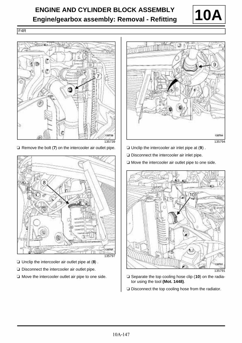
10A-147
ENGINE AND CYLINDER BLOCK ASSEMBLYEngine/gearbox assembly: Removal - Refitting
F4R
10A
a Remove the bolt (7) on the intercooler air outlet pipe.
a Unclip the intercooler air outlet pipe at (8) .
a Disconnect the intercooler air outlet pipe.
a Move the intercooler outlet air pipe to one side.
a Unclip the intercooler air inlet pipe at (9) .
a Disconnect the intercooler air inlet pipe.
a Move the intercooler air outlet pipe to one side.
a Separate the top cooling hose clip (10) on the radia-tor using the tool (Mot. 1448).
a Disconnect the top cooling hose from the radiator.
135739
135797
135794
135791

10A-148
ENGINE AND CYLINDER BLOCK ASSEMBLYEngine/gearbox assembly: Removal - Refitting
F4R
10A
a Separate the following on the radiator:
- the expansion bottle top cooling hose clip (Mot.1448) using the tool (11) ,
- the bottom cooling hose clip (12) using the tool(Mot. 1448).
a Disconnect:
- the expansion bottle top cooling hose,
- the radiator bottom cooling hose.
a Unclip from the front end panel:
- the wiring at (13) ,
- the expansion bottle top cooling hose.
a Remove the bolts (14) from the fan assembly wiringchannel.
a Remove:
- the front end panel clips (15) ,
- the front end panel upper bolts (16) .
135954
135511
135736
135719

10A-149
ENGINE AND CYLINDER BLOCK ASSEMBLYEngine/gearbox assembly: Removal - Refitting
F4R
10A
a Remove the lower bolts (17) from the front end pa-nel.
a Disconnect:
- the fan assembly connector (18) ,
- the fan unit resistor connector (19) .
a Unclip:
- the fan assembly wiring from the fan assembly at(20) ,
- the relay unit (21) from the front end panel.
a Move aside the fan assembly wiring.
a Remove the front end panel.
a Disconnect the connectors (22) from the battery dis-connection unit.
a Unclip the wiring of the offset positive terminal.
a Remove the power cable nuts (23) from the batterydisconnection unit.
a Move aside the power cables.
135296
135482
135508
135507

10A-150
ENGINE AND CYLINDER BLOCK ASSEMBLYEngine/gearbox assembly: Removal - Refitting
F4R
10A
a Unclip the power wiring channel (24) from the left-hand suspended engine mounting.
a Remove the air resonator (see 12A, Fuel mixture,Air resonator: Removal - Refitting, page 12A-1) .
a Remove the earth cable nut (25) on the body.
a Remove the cover (26) from the Protection and Swit-ching Unit.
a Disconnect the connectors (27) from the Protectionand Switching Unit.
a Remove:
- the Protection and Switching Unit,
- the engine wiring.
135506
135731
135721
135722

10A-151
ENGINE AND CYLINDER BLOCK ASSEMBLYEngine/gearbox assembly: Removal - Refitting
F4R
10A
a Remove:
- the bolts (28) from the engine fuse box,
- the nuts (29) from the engine fuse box.
a Move aside the engine fuse box.
a Remove the hydraulic clutch pipe (see Clutch cir-cuit: Removal - Refitting) (37A, Mechanical com-ponent controls).
a Unclip:
- the manual gearbox control cables from the selec-tor ball joints (30) using an open-jawed spanner,
- the manual gearbox control cables from their sup-port (31) .
a Unclip the vacuum pipe (32) from the brake servo.
a Move the brake servo vacuum pipe to one side.
a Remove the bolt (33) from the « intermediate pipe -compressor » connecting pipe.
a Uncouple the « intermediate pipe - compressor »connecting pipe from the intermediate pipe.
a Remove the seal from the « intermediate pipe -compressor » connecting pipe.
a Insert the blanking plugs.
135504
134244
137122
136492

10A-152
ENGINE AND CYLINDER BLOCK ASSEMBLYEngine/gearbox assembly: Removal - Refitting
F4R
10A
a Separate the clip (Mot. 1448) of the expansion bottlebottom cooling hose using the tool (34) .
a Disconnect the bottom cooling hose from the expan-sion bottle.
a Separate the heater matrix hose clips (35) using thetool (Mot. 1448).
a Disconnect the heater matrix hoses.
a Disconnect the petrol vapour rebreathing pipe (36) .
a Remove the petrol vapour rebreathing pipe.
a Disconnect the fuel supply pipe (37) on the injectorrail.
a Move aside the fuel supply pipe on the injector rail.
a Remove the radiator mounting cross member (seeRadiator support cross member: Removal - Re-fitting) (31A, Front axle components).
135501
135499
135779
134645
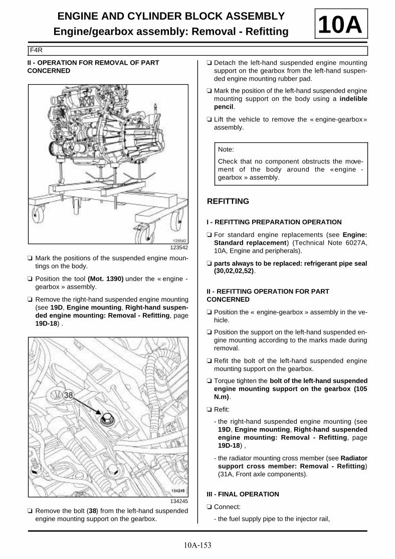
10A-153
ENGINE AND CYLINDER BLOCK ASSEMBLYEngine/gearbox assembly: Removal - Refitting
F4R
10AII - OPERATION FOR REMOVAL OF PART CONCERNED
a Mark the positions of the suspended engine moun-tings on the body.
a Position the tool (Mot. 1390) under the « engine -gearbox » assembly.
a Remove the right-hand suspended engine mounting(see 19D, Engine mounting, Right-hand suspen-ded engine mounting: Removal - Refitting, page19D-18) .
a Remove the bolt (38) from the left-hand suspendedengine mounting support on the gearbox.
a Detach the left-hand suspended engine mountingsupport on the gearbox from the left-hand suspen-ded engine mounting rubber pad.
a Mark the position of the left-hand suspended enginemounting support on the body using a indeliblepencil.
a Lift the vehicle to remove the « engine-gearbox »assembly.
REFITTING
I - REFITTING PREPARATION OPERATION
a For standard engine replacements (see Engine:Standard replacement) (Technical Note 6027A,10A, Engine and peripherals).
a parts always to be replaced: refrigerant pipe seal(30,02,02,52).
II - REFITTING OPERATION FOR PART CONCERNED
a Position the « engine-gearbox » assembly in the ve-hicle.
a Position the support on the left-hand suspended en-gine mounting according to the marks made duringremoval.
a Refit the bolt of the left-hand suspended enginemounting support on the gearbox.
a Torque tighten the bolt of the left-hand suspendedengine mounting support on the gearbox (105N.m).
a Refit:
- the right-hand suspended engine mounting (see19D, Engine mounting, Right-hand suspendedengine mounting: Removal - Refitting, page19D-18) ,
- the radiator mounting cross member (see Radiatorsupport cross member: Removal - Refitting)(31A, Front axle components).
III - FINAL OPERATION
a Connect:
- the fuel supply pipe to the injector rail,
123542
134245
Note:
Check that no component obstructs the move-ment of the body around the « engine -gearbox » assembly.
10A-154
ENGINE AND CYLINDER BLOCK ASSEMBLYEngine/gearbox assembly: Removal - Refitting
F4R
10A- the petrol vapour rebreathing pipe,
- the cooling hoses to the heater matrix,
- the expansion bottle bottom cooling hose.
a Fit:
- the heater matrix cooling hose clips using the tool(Mot. 1448),
- the clip of the expansion bottle bottom cooling hoseusing the tool (Mot. 1448).
a Remove the blanking plugs.
a Lubricate a new seal with the recommended air con-ditioning oil to make fitting easier (see Air conditio-ning: Parts and consumables for the repairwork) (62A, Air conditioning).
a Fit a new seal on the « intermediate pipe -compressor » connecting pipe.
a Couple the « intermediate pipe - compressor » con-necting pipe.
a Refit the bolt of the « intermediate pipe -compressor » connecting pipe.
a Torque tighten the bolt of the connecting pipebetween the « intermediate pipe - compressor »(8 N.m).
a Fit the brake servo vacuum pipe.
a Clip:
- brake servo vacuum pipe ,
- the control cables on the manual gearbox.
a Refit the hydraulic clutch pipe (see Clutch circuit:Removal - Refitting) (37A, Mechanical componentcontrols).
a Fit:
- the engine fuse box,
- the engine wiring.
a Connect the Protection and Switching Unit connec-tors.
a Fit the protection and switching unit.
a Refit:
- the Protection and Switching Unit cover,
- the earth cable nut on the body.
a Torque tighten the earth cable nut on the body (8N.m).
a Refit the air resonator (see 12A, Fuel mixture, Airresonator: Removal - Refitting, page 12A-1) .
a Clip the power wiring channel onto the left-hand sus-pended engine mounting.
a Position the power cables.
a Refit the power cable nuts on the battery disconnec-tion unit.
a Torque tighten the power cable nuts on the batte-ry disconnection unit (8 N.m).
a Clip on the wiring of the offset positive terminal.
a Connect the connectors of the battery disconnectionunit.
a Refit the front end panel.
a Clip:
- the relay unit on the front end panel,
- the fan assembly wiring.
a Connect:
- the fan unit resistor connector,
- the motor-driven fan assembly connector.
a Refit:
- the lower bolts from the front end panel,
- the front end panel upper bolts,
- the front end panel clips,
- the bolts of the fan assembly wiring channel.
a Clip:
- the wiring to the front end panel,
- the expansion bottle top cooling hose to the frontimpact cross member.
a Connect:
- the radiator bottom cooling hose,
- the expansion bottle top cooling hose,
- the radiator top cooling hose.
WARNING
Do not remove the blanking plugs from eachcomponent until the last moment.
Also, do not remove the components from theirpackaging until they are to be fitted to the vehi-cle.
WARNING
To avoid any leaks, check that the pipe surface issound before positioning the new seal. The sur-face must be clean and scratch free.

10A-155
ENGINE AND CYLINDER BLOCK ASSEMBLYEngine/gearbox assembly: Removal - Refitting
F4R
10Aa Fit the clip:
- of the radiator bottom cooling hose using the tool(Mot. 1448),
- of the expansion bottle top cooling hose using thetool (Mot. 1448),
- of the radiator top cooling hose using the tool (Mot.1448).
a Connect the intercooler air inlet pipe.
a Clip the intercooler air inlet pipe.
a Connect the intercooler air outlet pipe.
a Clip on the intercooler air outlet pipe.
a Refit the bolt on the intercooler air outlet pipe.
a Remove the blanking plugs.
a Lubricate a new seal with the recommended air con-ditioning oil to make fitting easier (see Air conditio-ning: Parts and consumables for the repairwork) (62A, Air conditioning).
a Fit a new seal on the « condenser - expansionvalve » connecting pipe on the condenser side.
a Couple the « condenser - expansion valve » con-necting pipe to the condenser.
a Refit the bolt of the « condenser - expansion valve »connecting pipe bracket on the condenser side.
a Torque tighten the bolt of the connecting pipebetween the « condenser - expansion valve » (8N.m).
a Remove the blanking plugs.
a Lubricate a new seal with the recommended air con-ditioning oil to make fitting easier (see Air conditio-ning: Parts and consumables for the repairwork) (62A, Air conditioning).
a Fit a new seal on the « compressor - condenser »connecting pipe on the condenser side.
a Couple the « compressor - condenser » connectingpipe on the condenser.
a Refit the bolt to the « compressor - condenser » con-necting pipe bracket on the condenser side.
a Torque tighten the bolt of the connecting pipebetween the « compressor - condenser » (8N.m).
a Refit the retaining bolt of the « compressor -condenser » connecting pipe
a Clip on the wiring of the refrigerant circuit pressuresensor.
a Connect the connector of the refrigerant circuit pres-sure sensor.
a Refit:
- the bonnet catch (see Bonnet latch: Removal -Refitting) (52A, Non-side opening element mecha-nisms),
- the front bumper mountings (see Front bumpersupport: Removal - Refitting) (42A, Front upperstructure),
- the headlights (see Front headlight: Removal -Refitting) (80B, Headlights),
- the side air deflectors,
- the upper air deflector,
- the front impact cross member (see Front impactcross member: Removal - Refitting) (41A, Frontlower structure),
- the audible warning (see Horn: Removal - Refit-ting) (82B, Horn),
- the connecting hose (see 19B, Exhaust, Connec-ting hose: Removal - Refitting, page 19B-60) ,
- the lower engine tie-bar (see 19D, Engine moun-ting, Lower engine tie-bar: Removal - Refitting,page 19D-33) ,
- new differential output seals (see Differential out-put seal: Removal - Refitting) (21A, Manual gear-box),
- the front left-hand wheel driveshaft (see Front left-hand wheel driveshaft: Removal - Refitting)(29A, Driveshafts),
- the front right-hand wheel driveshaft (see Front ri-ght-hand wheel driveshaft: Removal - Refitting)(29A, Driveshafts).
a Refill:
- the engine oil (if necessary) (see 10A, Engine andcylinder block assembly, Engine oil: Draining -Refilling, page 10A-40) ,
- the cooling circuit (see Manual gearbox oil: Drai-ning - Refilling) ,
- the manual gearbox (see Manual gearbox oil:Draining - Refilling) (21A, Manual gearbox),
- the refrigerant circuit using a refrigerant chargingstation (62A, Air conditioning).
a Refit:
- the front bumper (see Front bumper: Removal -Refitting) (55A, Exterior protection),
- the front section of the front wheel arch liners (seeFront wheel arch liner: Removal - Refitting)(55A, Exterior protection),

10A-156
ENGINE AND CYLINDER BLOCK ASSEMBLYEngine/gearbox assembly: Removal - Refitting
F4R
10A- the front wheels (see Wheel: Removal - Refitting)(35A, Wheels and tyres),
- the engine undertray,
- the air filter unit (see 12A, Fuel mixture, Air filterunit: Removal - Refitting, page 12A-4) ,
- the battery tray (see Battery tray: Removal - Re-fitting) (80A, Battery),
- the battery (see Battery : Removal - Refitting)(80A, Battery),
- the engine cover.
a Adjust the headlight beams (see Front headlight:Adjusting) (80B, Headlights).

10A-157
ENGINE AND CYLINDER BLOCK ASSEMBLYFlywheel: Removal - Refitting
K4M
10A
REMOVAL
I - REMOVAL PREPARATION OPERATION
a Position the vehicle on a two-post lift (see Vehicle:Towing and lifting) (02A, Lifting equipment).
a Remove:
- the engine cover,
- the windscreen wiper arms (see Windscreen wi-per arm: Removal - Refitting) (85A, Wiping -Washing),
- the scuttle panel grille (see Scuttle panel grille:Removal - Refitting) (56A, Exterior equipment),
- the scoop under the scuttle panel grille (see Scoopunder scuttle panel grille: Removal - Refitting)(56A, Exterior equipment),
- the battery (see Battery: Removal - Refitting)(80A, Battery),
- the battery tray (see Battery tray: Removal - Re-fitting) (80A, Battery),
- the air filter unit (see 12A, Fuel mixture, Air filterunit: Removal - Refitting, page 12A-4) .
a Loosen the clip on the throttle valve air inlet pipe.
a Disconnect the air outlet pipe from the air filter unit.
a Remove:
- the air outlet pipe to the air filter unit,
- the front wheels (see Wheel: Removal - Refitting)(35A, Wheels and tyres),
- the front section of the front wheel arch liners (seeFront wheel arch liner: Removal - Refitting)(55A, Exterior protection),
- the engine undertray bolts,
- the engine undertray,
- the front bumper (see Front bumper: Removal -Refitting) (55A, Exterior protection).
a Drain the manual gearbox (see Manual gearboxoil: Draining - Refilling) (21A, Manual gearbox).
a Remove:
- the starter (see 16A, Starting - Charging, Starter:Removal - Refitting, page 16A-16) ,
- the crankshaft position sensor (see 17B, Petrol in-jection, Crankshaft position sensor: Removal -Refitting, page 17B-15) ,
- the lower engine tie-bar (see 19D, Engine moun-ting, Lower engine tie-bar: Removal - Refitting,page 19D-33) ,
- the front right-hand wheel driveshaft (see Front ri-ght-hand wheel driveshaft: Removal - Refitting)(29A, Driveshafts),
- the front left-hand wheel driveshaft (see Front left-hand wheel driveshaft: Removal - Refitting)(29A, Driveshafts),
- the differential output seals (see Differential out-put seal: Removal - Refitting) (21A, Manual gear-box),
- the radiator mounting cross member (see Radiatorsupport cross member: Removal - Refitting)(31A, Front axle components),
- the front axle subframe (see Front axle sub-fra-me: Removal - Refitting) (31A, Front axle compo-nents),
- the left-hand suspended engine mounting (see19D, Engine mounting, Left-hand suspendedengine mounting: Removal - Refitting, page19D-1) ,
- the manual gearbox (see Manual gearbox: Remo-val - Refitting) (21A, Manual gearbox).
- the « pressure plate - disc » assembly (see Me-chanism / Disk: Removal - Refitting) (20A,Clutch).
Essential special tooling
Mot. 1677 Flywheel locking tool.
Tightening torquesm
new flywheel bolts 25 N.m + 50˚ ±±±±6˚
clip on the throttle valveair inlet pipe
6 N.m

10A-158
ENGINE AND CYLINDER BLOCK ASSEMBLYFlywheel: Removal - Refitting
K4M
10AII - OPERATION FOR REMOVAL OF PART CONCERNED
a Lock the flywheel using tool (Mot. 1677) (1) .
a Remove:
- the flywheel bolts,
- the flywheel,
- the (Mot. 1677).
REFITTING
I - REFITTING PREPARATION OPERATION
a parts always to be replaced: Flywheel bolts (10,03,03,14).
a Use SURFACE CLEANER (see Vehicle: Parts and ingredients for the repairwork) (04B, Consu-mables - Products) to clean and degrease:
- the flywheel bearing face if reusing,
- the crankshaft bearing face.
a Check the condition of the flywheel and its seal.
II - REFITTING OPERATION FOR PART CONCERNED
a Position the flywheel equipped with new bolts.
a Fit the new bolts on the flywheel without tighteningthem.
a Position the (Mot. 1677).
a Tighten to torque and in order the new flywheelbolts (25 N.m + 50˚ ±±±± 6˚).
a Remove the (Mot. 1677).
III - FINAL OPERATION
a Refit:
- the « pressure plate - disc » assembly (see Me-chanism / Disk: Removal - Refitting) (20A,Clutch),
- the manual gearbox (see Manual gearbox: Remo-val - Refitting) (21A, Manual gearbox).
- the left-hand suspended engine mounting (see19D, Engine mounting, Left-hand suspendedengine mounting: Removal - Refitting, page19D-1) ,
- the front axle subframe (see Front axle sub-fra-me: Removal - Refitting) (31A, Front axle compo-nents),
- the radiator mounting cross member (see Radiatorsupport cross member: Removal - Refitting)(31A, Front axle components),
134546 134545
10A-159
ENGINE AND CYLINDER BLOCK ASSEMBLYFlywheel: Removal - Refitting
K4M
10A- the new differential output seals (see Differentialoutput seal: Removal - Refitting) (21A, Manualgearbox),
- the front right-hand wheel driveshaft (see Front ri-ght-hand wheel driveshaft: Removal - Refitting)(29A, Driveshafts),
- the front left-hand wheel driveshaft (see Front left-hand wheel driveshaft: Removal - Refitting)(29A, Driveshafts),
- the lower engine tie-bar (see 19D, Engine moun-ting, Lower engine tie-bar: Removal - Refitting,page 19D-33) ,
- the crankshaft position sensor (see 17B, Petrol in-jection, Crankshaft position sensor: Removal -Refitting, page 17B-15) ,
- the starter (see 16A, Starting - Charging, Starter:Removal - Refitting, page 16A-16) ,
- the front bumper (see Front bumper: Removal -Refitting) (55A, Exterior protection),
- the engine undertray,
- the front section of the front wheel arch liners (seeFront wheel arch liner: Removal - Refitting)(55A, Exterior protection),
- the front wheels (see Wheel: Removal - Refitting)(35A, Wheels and tyres),
- the air filter unit (see 12A, Fuel mixture, Air filterunit: Removal - Refitting, page 12A-4) ,
- the air filter unit air outlet pipe.
a Connect the air outlet pipe of the air filter unit.
a Torque tighten the clip on the throttle valve air in-let pipe (6 N.m).
a Refit:
- the battery tray (see Battery tray: Removal - Re-fitting) (80A, Battery),
- the battery (see Battery: Removal - Refitting)(80A, Battery),
- the scoop under the scuttle panel grille (see Scoopunder scuttle panel grille: Removal - Refitting)(56A, Exterior equipment),
- the scuttle panel grille (see Scuttle panel grille:Removal - Refitting) (56A, Exterior equipment),
- the windscreen wiper arms (see Windscreen wi-per arm: Removal - Refitting) (85A, Wiping -Washing).
a Perform the following operations:
- fill the manual gearbox with oil (see Manual gear-box oil: Draining - Refilling) (21A, Manual gear-box),
- bleed the clutch control circuit (see Clutch circuit:Removal - Refitting) (37A, Mechanical compo-nent controls).
a Refit the engine cover.

10A-160
ENGINE AND CYLINDER BLOCK ASSEMBLYFlywheel: Removal - Refitting
K9K
10A
REMOVAL
I - REMOVAL PREPARATION OPERATION
a Position the vehicle on a two-post lift (see Vehicle:Towing and lifting) (02A, Lifting equipment).
a Remove:
- the engine cover,
- the battery (see Battery : Removal - Refitting)(80A, Battery),
- the battery tray (see Battery tray: Removal - Re-fitting) (80A, Battery),
- the air filter unit (see 12A, Fuel mixture, Air filterunit: Removal - Refitting, page 12A-4) ,
- the engine undertray bolts,
- the engine undertray,
- the crankshaft position sensor (see 13B, Diesel in-jection, Crankshaft position sensor: Removal -Refitting, page 13B-25) ,
- the starter (see 16A, Starting - Charging, Starter:Removal - Refitting, page 16A-16) ,
- the front wheels (see Wheel: Removal - Refitting)(35A, Wheels and tyres),
- the front section of the front wheel arch liners (seeFront wheel arch liner: Removal - Refitting)(55A, Exterior protection).
a Drain the gearbox (see Manual gearbox oil: Drai-ning - Refilling) .
a Remove:
- the front left-hand wheel driveshaft (see Front left-hand wheel driveshaft: Removal - Refitting)(29A, Driveshafts),
- the front right-hand wheel driveshaft (see Front ri-ght-hand wheel driveshaft: Removal - Refitting)(29A, Driveshafts),
- the differential output seals (see Differential out-put seal: Removal - Refitting) (21A, Manual gear-box).
a Remove the lower engine tie-bar (see 19D, Enginemounting, Lower engine tie-bar: Removal - Refit-ting, page 19D-33) .
a Remove:
- the front bumper (see Front bumper: Removal -Refitting) (55A, Exterior protection),
- the radiator mounting cross member (see Radiatorsupport cross member: Removal - Refitting)(31A, Front axle components),
- the front axle subframe (see Front axle sub-fra-me: Removal - Refitting) (31A, Front axle compo-nents),
- the windscreen wiper arms (see Windscreen wi-per arm: Removal - Refitting) (85A, Wiping -Washing),
- the scuttle panel grille (see Scuttle panel grille:Removal - Refitting) (56A, Exterior equipment),
- the scoop under the scuttle panel grille (see Scoopunder scuttle panel grille: Removal - Refitting)(56A, Exterior equipment),
- the left-hand suspended engine mounting (see19D, Engine mounting, Left-hand suspendedengine mounting: Removal - Refitting, page19D-1) ,
- the manual gearbox (see Manual gearbox: Remo-val - Refitting) (21A, Manual gearbox).
- the hydraulic clutch release bearing (see Clutchthrust bearing: Removal - Refitting) (20A,Clutch),
- the clutch disc and pressure plate (see Mecha-nism / Disk: Removal - Refitting) (20A, Clutch).
Essential special tooling
Mot. 582 Flywheel locking tool.
Tightening torquesm
flywheel bolts 20 N.m + 36˚ ±±±±6˚
flywheel bolts 50 N.m
IMPORTANTConsult the safety and cleanliness advice and ope-ration recommendations before carrying out anyrepair (see Clutch: Precautions for repair) .
JR5

10A-161
ENGINE AND CYLINDER BLOCK ASSEMBLYFlywheel: Removal - Refitting
K9K
10AII - OPERATION FOR REMOVAL OF PART CONCERNED
a Lock the flywheel using tool (Mot. 582) (1) .
a Remove:
- the flywheel bolts (2) ,
- the flywheel,
- the (Mot. 582).
a Lock the flywheel using tool (Mot. 582) (1) .
a Remove:
- the flywheel bolts (2) ,
- the flywheel,
- the (Mot. 582).
REFITTING
I - REFITTING PREPARATION OPERATION
a Always replace:
- the flywheel bolts,
- the differential output seals.
a Clean the flywheel threads using SURFACE CLEA-NER (see Vehicle: Parts and ingredients for therepairwork) (04B, Consumables - Products).
a Degrease the flywheel bearing faces using SURFA-CE CLEANER (see Vehicle: Parts and ingre-dients for the repairwork) (04B, Consumables -Products).
TL4
134218
JR5
135857
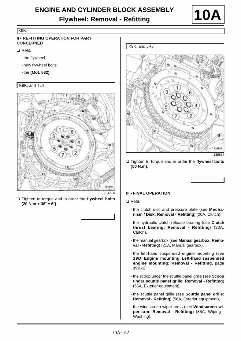
10A-162
ENGINE AND CYLINDER BLOCK ASSEMBLYFlywheel: Removal - Refitting
K9K
10AII - REFITTING OPERATION FOR PART CONCERNED
a Refit:
- the flywheel,
- new flywheel bolts.
- the (Mot. 582).
a Tighten to torque and in order the flywheel bolts(20 N.m + 36˚ ±±±± 6˚).
a Tighten to torque and in order the flywheel bolts(50 N.m).
III - FINAL OPERATION
a Refit:
- the clutch disc and pressure plate (see Mecha-nism / Disk: Removal - Refitting) (20A, Clutch),
- the hydraulic clutch release bearing (see Clutchthrust bearing: Removal - Refitting) (20A,Clutch),
- the manual gearbox (see Manual gearbox: Remo-val - Refitting) (21A, Manual gearbox).
- the left-hand suspended engine mounting (see19D, Engine mounting, Left-hand suspendedengine mounting: Removal - Refitting, page19D-1) ,
- the scoop under the scuttle panel grille (see Scoopunder scuttle panel grille: Removal - Refitting)(56A, Exterior equipment),
- the scuttle panel grille (see Scuttle panel grille:Removal - Refitting) (56A, Exterior equipment),
- the windscreen wiper arms (see Windscreen wi-per arm: Removal - Refitting) (85A, Wiping -Washing),
K9K, and TL4
134218
K9K, and JR5
135857

10A-163
ENGINE AND CYLINDER BLOCK ASSEMBLYFlywheel: Removal - Refitting
K9K
10A- the front axle subframe (see Front axle sub-fra-me: Removal - Refitting) (31A, Front axle compo-nents),
- the radiator mounting cross member (see Radiatorsupport cross member: Removal - Refitting)(31A, Front axle components),
- the front bumper (see Front bumper: Removal -Refitting) (55A, Exterior protection).
a Refit the lower engine tie-bar (see 19D, Enginemounting, Lower engine tie-bar: Removal - Refit-ting, page 19D-33) .
a Refit:
- the new differential output seals (see Differentialoutput seal: Removal - Refitting) (21A, Manualgearbox),
- the front right-hand wheel driveshaft (see Front ri-ght-hand wheel driveshaft: Removal - Refitting)(29A, Driveshafts),
- the front left-hand wheel driveshaft (see Front left-hand wheel driveshaft: Removal - Refitting)(29A, Driveshafts).
a Fill the manual gearbox (see Manual gearbox oil:Draining - Refilling) (21A, Manual gearbox).
a Refit:
- the front section of the front wheel arch liners (seeFront wheel arch liner: Removal - Refitting)(55A, Exterior protection),
- the front wheels (see Wheel: Removal - Refitting)(35A, Wheels and tyres),
- the starter (see 16A, Starting - Charging, Starter:Removal - Refitting, page 16A-16) ,
- the crankshaft position sensor (see 13B, Diesel in-jection, Crankshaft position sensor: Removal -Refitting, page 13B-25) .
a Bleed the clutch control circuit (see Clutch circuit:Bleeding) (37A, Mechanical component controls).
a Refit:
- the engine undertray,
- the air filter unit (see 12A, Fuel mixture, Air filterunit: Removal - Refitting, page 12A-4) ,
- the battery tray (see Battery tray: Removal - Re-fitting) (80A, Battery),
- the battery (see Battery : Removal - Refitting)(80A, Battery),
- the engine cover.
JR5

10A-164
ENGINE AND CYLINDER BLOCK ASSEMBLYFlywheel: Removal - Refitting
F9Q
10A
REMOVAL
I - REMOVAL PREPARATION OPERATION
a Position the vehicle on a two-post lift (see Vehicle:Towing and lifting) (02A, Lifting equipment).
a Remove:
- the engine cover,
- the engine undertray bolts,
- the engine undertray,
- the battery (see Battery : Removal - Refitting)(80A, Battery),
- the battery tray (see Battery tray: Removal - Re-fitting) (80A, Battery),
- the windscreen wiper arms (see Windscreen wi-per arm: Removal - Refitting) (85A, Wiping -Washing),
- the scuttle panel grille (see Scuttle panel grille:Removal - Refitting) (56A, Exterior equipment),
- the scoop under the scuttle panel grille (see Scoopunder scuttle panel grille: Removal - Refitting)(56A, Exterior equipment),
- the front wheels (see Wheel: Removal - Refitting)(35A, Wheels and tyres),
- the front wheel arch liners (see Front wheel archliner: Removal - Refitting) (55A, Exterior protec-tion),
- the starter (see 16A, Starting - Charging, Starter:Removal - Refitting, page 16A-16) .
a Drain the manual gearbox (see Manual gearboxoil: Draining - Refilling) (21A, Manual gearbox).
a Remove:
- the front left-hand wheel driveshaft (see Front left-hand wheel driveshaft: Removal - Refitting)(29A, Driveshafts),
- the front right-hand wheel driveshaft (see Front ri-ght-hand wheel driveshaft: Removal - Refitting)(29A, Driveshafts),
- the radiator mounting cross member (see Radiatorsupport cross member: Removal - Refitting)(41A, Front lower structure),
- the front axle subframe (see Front axle sub-fra-me: Removal - Refitting) (31A, Front axle compo-nents),
- the left-hand suspended engine mounting (see19D, Engine mounting, Left-hand suspendedengine mounting: Removal - Refitting, page19D-1) ,
- the manual gearbox (see Manual gearbox: Remo-val - Refitting) (21A, Manual gearbox),
- the « pressure plate - disc » assembly (see Me-chanism / Disk: Removal - Refitting) (20A,Clutch).
II - OPERATION FOR REMOVAL OF PART CONCERNED
a Remove:
- the flywheel bolts,
- the (Mot. 1677) (1) ,
- the flywheel.
Essential special tooling
Mot. 1677 Flywheel locking tool.
Tightening torquesm
flywheel bolts 30 N.m + 62˚
IMPORTANT
Consult the safety and cleanliness advice and ope-ration recommendations before carrying out anyrepair (see Clutch: Precautions for repair) .
22698

10A-165
ENGINE AND CYLINDER BLOCK ASSEMBLYFlywheel: Removal - Refitting
F9Q
10AREFITTING
I - REFITTING PREPARATION OPERATION
a Use SURFACE CLEANER (see Vehicle: Parts and ingredients for the repairwork) (04B, Consu-mables - Products) to clean and degrease:
- the flywheel pressure face on the crankshaft,
- the flywheel threading on the crankshaft.
a parts always to be replaced: Flywheel bolts (10,03,03,14).
II - REFITTING OPERATION FOR PART CONCERNED
a Fit the flywheel.
a Screw in the new flywheel bolts without tighteningthem.
a Position the (Mot. 1677).
a Torque and angle tighten the flywheel bolts (30N.m + 62˚).
III - FINAL OPERATION
a Refit:
- the « pressure plate - disc » assembly (see Me-chanism / Disk: Removal - Refitting) (21A, Ma-nual gearbox),
- the manual gearbox (see Manual gearbox: Remo-val - Refitting) (20A, Clutch),
- the left-hand suspended engine mounting (see19D, Engine mounting, Left-hand suspendedengine mounting: Removal - Refitting, page19D-1) ,
- the front axle subframe (see Front axle sub-fra-me: Removal - Refitting) (31A, Front axle compo-nents),
- the radiator mounting cross member (see Radiatorsupport cross member: Removal - Refitting)(41A, Front lower structure).
- the front left-hand wheel driveshaft (see Front left-hand wheel driveshaft: Removal - Refitting)(29A, Driveshafts),
- the front right-hand wheel driveshaft (see Front ri-ght-hand wheel driveshaft: Removal - Refitting)(29A, Driveshafts),
- the starter (see 16A, Starting - Charging, Starter:Removal - Refitting, page 16A-16) ,
- the front wheel arch liners (see Front wheel archliner: Removal - Refitting) (55A, Exterior protec-tion),
- the front wheels (see Wheel: Removal - Refitting)(35A, Wheels and tyres),
- the scoop under the scuttle panel grille (see Scoopunder scuttle panel grille: Removal - Refitting)(56A, Exterior equipment),
- the scuttle panel grille (see Scuttle panel grille:Removal - Refitting) (56A, Exterior equipment),
- the windscreen wiper arms (see Windscreen wi-per arm: Removal - Refitting) (85A, Wiping -Washing),
- the battery tray (see Battery tray: Removal - Re-fitting) (80A, Battery),
- the battery (see Battery : Removal - Refitting)(80A, Battery),
a Fill the manual gearbox (see Manual gearbox oil:Draining - Refilling) (21A, Manual gearbox).
a Refit:
- the engine undertray,
- the engine cover.

10A-166
ENGINE AND CYLINDER BLOCK ASSEMBLYFlywheel: Removal - Refitting
F4R
10A
REMOVAL
I - REMOVAL PREPARATION OPERATION
a Position the vehicle on a two-post lift (see Vehicle:Towing and lifting) (02A, Lifting equipment).
a Remove:
- the engine cover,
- the battery (see Battery : Removal - Refitting)(80A, Battery),
- the battery tray (see Battery tray: Removal - Re-fitting) (80A, Battery),
- the air filter unit (see 12A, Fuel mixture, Air filterunit: Removal - Refitting, page 12A-4) ,
- the front wheels (see Wheel: Removal - Refitting)(35A, Wheels and tyres),
- the engine undertray bolts,
- the engine undertray.
a Drain the manual gearbox (see Manual gearboxoil: Draining - Refilling) (21A, Manual gearbox).
a Remove:
- the front section of the front wheel arch liners (seeFront wheel arch liner: Removal - Refitting)(55A, Exterior protection),
- the front bumper (see Front bumper: Removal -Refitting) (55A, Exterior protection),
- the radiator mounting cross member (see Radiatorsupport cross member: Removal - Refitting)(31A, Front axle components),
- the front right-hand wheel driveshaft (see Front ri-ght-hand wheel driveshaft: Removal - Refitting)(29A, Driveshafts),
- the front left-hand wheel driveshaft (see Front left-hand wheel driveshaft: Removal - Refitting)(29A, Driveshafts),
- the differential output seals (see Differential out-put seal: Removal - Refitting) (21A, Manual gear-box),
- the lower engine tie-bar (see 19D, Engine moun-ting, Lower engine tie-bar: Removal - Refitting,page 19D-33) ,
- the front axle subframe (see Front axle sub-fra-me: Removal - Refitting) (31A, Front axle compo-nents),
- the starter (see 16A, Starting - Charging, Starter:Removal - Refitting, page 16A-16) ,
- the windscreen wiper arms (see Windscreen wi-per arm: Removal - Refitting) (85A, Wiping -Washing),
- the scuttle panel grille (see Scuttle panel grille:Removal - Refitting) (56A, Exterior equipment),
- the scoop under the scuttle panel grille (see Scoopunder scuttle panel grille: Removal - Refitting)(56A, Exterior equipment),
- the left-hand suspended engine mounting (see19D, Engine mounting, Left-hand suspendedengine mounting: Removal - Refitting, page19D-1) ,
- the manual gearbox (see Manual gearbox: Remo-val - Refitting) (21A, Manual gearbox),
- the pressure plate - disc assembly (see Mecha-nism / Disk: Removal - Refitting) (20A, Clutch).
Essential special tooling
Mot. 1431 Flywheel locking tool.
Tightening torquesm
flywheel bolts 30 N.m + 56˚ ±±±±6˚
IMPORTANT
To prevent the vehicle from falling, lash it to thevehicle lift using a strap.

10A-167
ENGINE AND CYLINDER BLOCK ASSEMBLYFlywheel: Removal - Refitting
F4R
10AII - OPERATION FOR REMOVAL OF PART CONCERNED
a Lock the flywheel using tool (Mot. 1431) (1) .
a Remove:
- the flywheel bolts (2) ,
- the (Mot. 1431),
- the flywheel.
REFITTING
I - REFITTING PREPARATION OPERATION
a parts always to be replaced: Flywheel bolts (10,03,03,14).
a Use SURFACE CLEANER (see Vehicle: Parts and ingredients for the repairwork) (04B, Consu-mables - Products) to clean and degrease:
- the flywheel bearing faces if reusing,
- the bearing faces of the crankshaft.
II - REFITTING OPERATION FOR PART CONCERNED
a Refit:
- the flywheel,
- new flywheel bolts.
a Position the (Mot. 1431).
a Torque tighten in order the flywheel bolts (30 N.m+ 56˚ ±±±± 6˚).
III - FINAL OPERATION
a Refit:
- the pressure plate - disc assembly (see Mecha-nism / Disk: Removal - Refitting) (20A, Clutch),
- the manual gearbox (see Manual gearbox: Remo-val - Refitting) (21A, Manual gearbox),
- the left-hand suspended engine mounting (see19D, Engine mounting, Left-hand suspendedengine mounting: Removal - Refitting, page19D-1) ,
- the scoop under the scuttle panel grille (see Scoopunder scuttle panel grille: Removal - Refitting)(56A, Exterior equipment),
- the scuttle panel grille (see Scuttle panel grille:Removal - Refitting) (56A, Exterior equipment),
- the windscreen wiper arms (see Windscreen wi-per arm: Removal - Refitting) (85A, Wiping -Washing),
- the starter (see 16A, Starting - Charging, Starter:Removal - Refitting, page 16A-16) ,
- the new differential output seals (see Differentialoutput seal: Removal - Refitting) (21A, Manualgearbox),
134249
134249

10A-168
ENGINE AND CYLINDER BLOCK ASSEMBLYFlywheel: Removal - Refitting
F4R
10A- the front axle subframe (see Front axle sub-fra-me: Removal - Refitting) (31A, Front axle compo-nents),
- the lower engine tie-bar (see 19D, Engine moun-ting, Lower engine tie-bar: Removal - Refitting,page 19D-33) ,
- the front left-hand wheel driveshaft (see Front left-hand wheel driveshaft: Removal - Refitting)(29A, Driveshafts),
- the front right-hand wheel driveshaft (see Front ri-ght-hand wheel driveshaft: Removal - Refitting)(29A, Driveshafts),
- the radiator mounting cross member (see Radiatorsupport cross member: Removal - Refitting)(31A, Front axle components),
- the front bumper (see Front bumper: Removal -Refitting) (55A, Exterior protection),
- the front section of the front wheel arch liners (seeFront wheel arch liner: Removal - Refitting)(55A, Exterior protection),
a Fill the manual gearbox (see Manual gearbox oil:Draining - Refilling) (21A, Manual gearbox).
a Refit:
- the engine undertray,
- the front wheels (see Wheel: Removal - Refitting)(35A, Wheels and tyres),
- the air filter unit (see 12A, Fuel mixture, Air filterunit: Removal - Refitting, page 12A-4) ,
- the battery tray (see Battery tray: Removal - Re-fitting) (80A, Battery),
- the battery (see Battery : Removal - Refitting)(80A, Battery),
- the engine cover.

11A-1
TOP AND FRONT OF ENGINEFinal compression pressure: Check
K4M
11A
CHECKING
I - PREPARATION OPERATION FOR CHECK
a Remove
- the engine cover,
- the ignition coils (see 17A, Ignition, Coils Remo-val - Refitting, page 17A-1) ,
- the spark plugs (see 17A, Ignition, Spark plugs:Removal - Refitting, page 17A-5) .
a Connect a petrol compression gauge (1) .
a Run command with diagnostic tool :
- RZ003 : "ADAPTATIFS MOTEUR",
- VP036 : "INHIBITION ALIMENTATION CARBU-RANT".
a Put the vehicle under starting conditions:
- gear lever in neutral position for manual gearbox,
- brake pedal depressed.
II - TEST OPERATION
a Press the vehicle start button to trigger the enginestarting phase.
a Measure the compression of cylinder no.1.
a Fully depress the accelerator pedal in order to openthe throttle valve during the compression measure-ments.
a Measure the compression of the other cylinders.
III - FINAL OPERATION
a Disconnect the petrol compression gauge.
a Refit:
- the spark plugs (see 17A, Ignition, Spark plugs:Removal - Refitting, page 17A-5) ,
- the ignition coils (see 17A, Ignition, Coils Remo-val - Refitting, page 17A-1) ,
- the engine cover.
a Remove the card from the reader to interrupt the +after ignition feed and wait for the loss of communi-cation message to appear on the diagnostic tool.
a When the loss of communication message appearsor after waiting 9 minutes, force the vehicle's + afterignition feed.
Essential equipment
petrol compression gauge
diagnostic tool
136451
Note:
The engine will be driven by the starter for 20seconds, without being started.
Note:
Put the vehicle under forced + after ignition feedas soon as the starter has stopped (in order tomaintain the inhibition of the engine starting andto be able to measure the compression of theother cylinders).
Note:
It is necessary to wait for at least 10 secondsbefore starting the engine each time (the starterwill not run due to its thermal protection).
Note:
If the message does not appear, wait 9 minutes.

11A-2
TOP AND FRONT OF ENGINEFinal compression pressure: Check
K9K
11A
CHECKING
I - PREPARATION OPERATION FOR CHECK
a Remove the preheater plugs (see 13C, Preheating,Heater plugs Removal - Refitting, page 13C-3) .
a Disconnect:
- the connector (1) from the fuel pressure regulationsolenoid valve,
- the connector (2) from the fuel flow regulating sole-noid valve.
a Disconnect the connector (3) from the fuel pressureregulation solenoid valve.
II - TEST OPERATION
a Use an open-jawed spanner to moderately tighten:
- the hose end piece (Mot. 1592),
Essential special tooling
Mot. 1592 Compression pressure testend piece-hose.
Essential equipment
diesel compression gauge
self-contained starter
diagnostic tool
K9K, and 832
134706
K9K, and 830
135874
136734

11A-3
TOP AND FRONT OF ENGINEFinal compression pressure: Check
K9K
11A- the adapter of the diesel compression gauge onthe (Mot. 1592).
a Moderately tighten the unions of the diesel com-pression gauge using an open-jawed spanner.
a Connect the self-contained starter.
a Force the vehicle's + after ignition feed.
a Connect the diagnostic tool.
a Run commands:
- RZ009 "Program vehicle functions",
- VP036 "Inhibit fuel supply".
a Operate the starter for 15 seconds until the needleof the diesel compression gauge stabilises to ob-tain the maximum value.
a Make progress with the diagram sheet.
a Carry out the same procedure for the other cylin-ders.
a Check that the cylinder compression values are allapproximately equal.
a Run command VP037 "Stop fuel supply inhibition".
a Disconnect:
- the diagnostic tool,
- the self-contained starter.
a Undo:
- the diesel compression gauge on the hose endpiece (Mot. 1592),
- the flexible end piece (Mot. 1592) using an open-jawed spanner.
a Remove the flexible end piece (Mot. 1592) whichwas fitted in place of one of the removed plugs.
III - FINAL OPERATION
a Connect the connector to the fuel flow regulation so-lenoid valve.
a Connect the connector to the fuel pressure regula-tion solenoid valve.
a Refit the heater plugs (see 13C, Preheating, Heaterplugs Removal - Refitting, page 13C-3) .136733
Note:
The pressure value after compression must be atleast 18 bar.
K9K, and 832
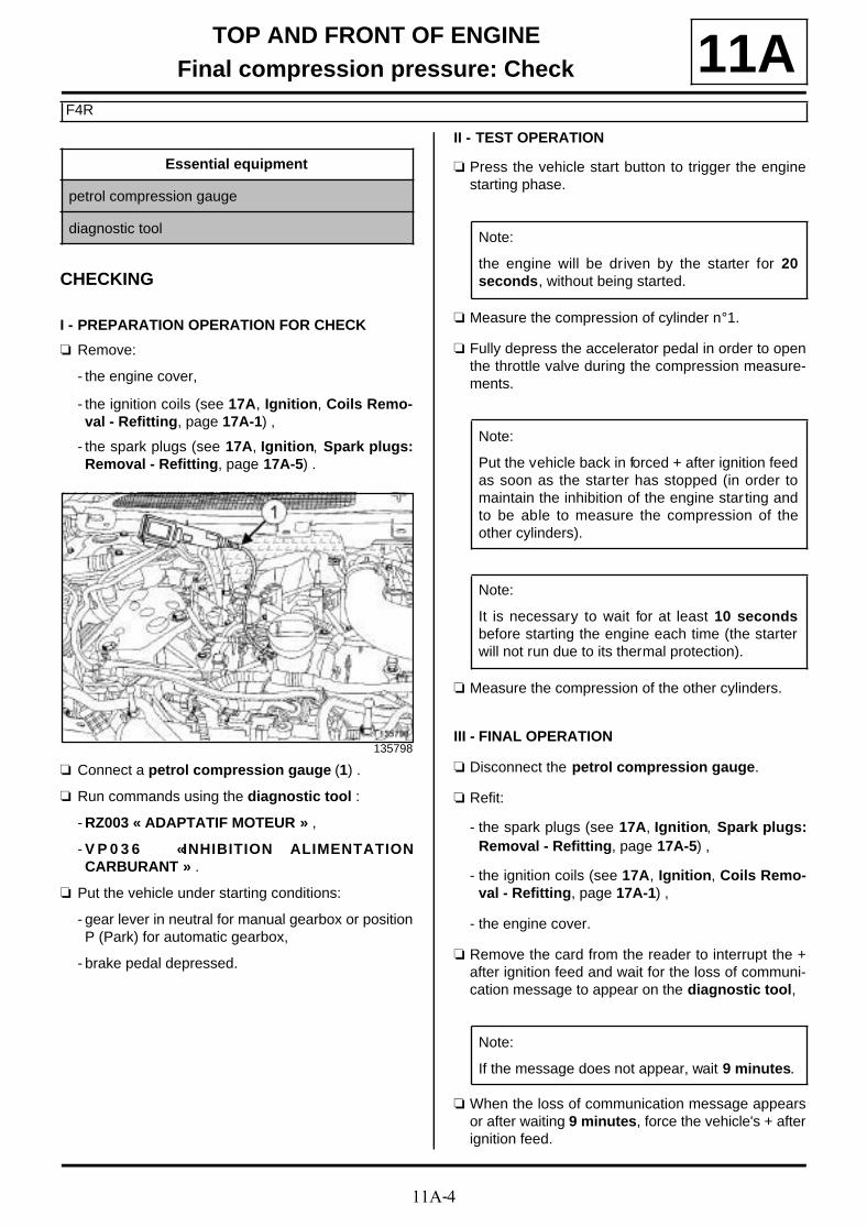
11A-4
TOP AND FRONT OF ENGINEFinal compression pressure: Check
F4R
11A
CHECKING
I - PREPARATION OPERATION FOR CHECK
a Remove:
- the engine cover,
- the ignition coils (see 17A, Ignition, Coils Remo-val - Refitting, page 17A-1) ,
- the spark plugs (see 17A, Ignition, Spark plugs:Removal - Refitting, page 17A-5) .
a Connect a petrol compression gauge (1) .
a Run commands using the diagnostic tool :
- RZ003 « ADAPTATIF MOTEUR » ,
- V P 0 3 6 « INHIBITION ALIMENTATIONCARBURANT » .
a Put the vehicle under starting conditions:
- gear lever in neutral for manual gearbox or positionP (Park) for automatic gearbox,
- brake pedal depressed.
II - TEST OPERATION
a Press the vehicle start button to trigger the enginestarting phase.
a Measure the compression of cylinder n°1.
a Fully depress the accelerator pedal in order to openthe throttle valve during the compression measure-ments.
a Measure the compression of the other cylinders.
III - FINAL OPERATION
a Disconnect the petrol compression gauge.
a Refit:
- the spark plugs (see 17A, Ignition, Spark plugs:Removal - Refitting, page 17A-5) ,
- the ignition coils (see 17A, Ignition, Coils Remo-val - Refitting, page 17A-1) ,
- the engine cover.
a Remove the card from the reader to interrupt the +after ignition feed and wait for the loss of communi-cation message to appear on the diagnostic tool,
a When the loss of communication message appearsor after waiting 9 minutes, force the vehicle's + afterignition feed.
Essential equipment
petrol compression gauge
diagnostic tool
135798
Note:
the engine will be driven by the starter for 20seconds, without being started.
Note:
Put the vehicle back in forced + after ignition feedas soon as the starter has stopped (in order tomaintain the inhibition of the engine starting andto be able to measure the compression of theother cylinders).
Note:
It is necessary to wait for at least 10 secondsbefore starting the engine each time (the starterwill not run due to its thermal protection).
Note:
If the message does not appear, wait 9 minutes.

11A-5
TOP AND FRONT OF ENGINEFinal compression pressure: Check
F9Q
11A
CHECKING
I - PREPARATION OPERATION FOR CHECK
a Remove:
- the engine cover,
- the injector rail protector (see 13B, Diesel injec-tion, Injector rail protector: Removal - Refitting,page 13B-70) ,
- the heater plugs (see 13C, Preheating, Heaterplugs Removal - Refitting, page 13C-3) .
a Fit the hose end piece (Mot. 1592) in place of theheater plug on the cylinder to be checked.
a Use an open-jawed spanner to moderately tighten:
- the hose end piece (Mot. 1592),
- the diesel compression gauge.
a Connect a self-contained starter.
a Force the vehicle's + after ignition feed.
a Connect the diagnostic tool.
a Run commands:
- RZ009: "VEHICLE FUNCTION PROGRAM-MING",
- VP036: "INHIBIT FUEL SUPPLY".
II - TEST OPERATION
a Run the starter.
a Proceed through the diagram sheet.
a Carry out the same procedure for the other cylin-ders.
III - FINAL OPERATION
a Remove:
- the diesel compression gauge,
- the hose end piece (Mot. 1592).
a Refit:
- the heater plugs (see 13C, Preheating, Heaterplugs Removal - Refitting, page 13C-3) ,
- the injector rail protector (see 13B, Diesel injec-tion, Injector rail protector: Removal - Refitting,page 13B-70) ,
- the engine cover.
Essential special tooling
Mot. 1592 Compression pressure testend piece-hose.
Essential equipment
diesel compression gauge
self-contained starter
diagnostic tool
137751
Note:
The engine will be driven by the starter for 20seconds, without being started.
Note:
Put the vehicle under forced + after ignition feedas soon as the star ter has been stopped (inorder to maintain the inhibition of the engine star-ting and to be able to measure the compressionof the other cylinders).
Note:
It is necessary to wait for at least 10 secondsbefore starting the engine each time (the starterwill not run due to its thermal protection).

11A-6
TOP AND FRONT OF ENGINEFinal compression pressure: Check
F9Q
11Aa Remove the card from the reader to interrupt the +
after ignition feed and wait for the loss of communi-cation message to appear on the diagnostic tool.
a When the loss of communication message appearsor after waiting 9 minutes, force the vehicle's + afterignition feed.
Note:
If the message does not appear, wait 9 minutes.

11A-7
TOP AND FRONT OF ENGINEAccessories belt: Removal - Refitting
K4M
11A
REMOVAL
I - REMOVAL PREPARATION OPERATION
a Position the vehicle on a two-post lift (see Vehicle:Towing and lifting) (02A, Lifting equipment).
a Remove:
- the front right-hand wheel (see Wheel: Removal -Refitting) (35A, Wheels and tyres),
- the front section of the front right-hand wheel archliner (see Front wheel arch liner: Removal - Re-fitting) (55A, Exterior protection).
II - OPERATION FOR REMOVAL OF PART CONCERNED
a Turn the accessories belt auto tensioner clockwiseusing a 16 mm spanner.
a Lock the tensioning roller using a 6 mm Allen key.
a Remove the accessories belt.
a Remove:
- the tensioning roller bolt,
- the tensioning roller.
REFITTING
I - REFITTING PREPARATION OPERATION
a parts always to be replaced: Accessories belt(10,10,01,03).
a parts always to be replaced: Accessories belttensioning roller (10,10,01,04).
a Use a brush to remove any deposits from thecrankshaft pulley V-grooves.
II - REFITTING OPERATION FOR PART CONCERNED
a Refit a new tensioning roller.
Tightening torquesm
tensioning roller bolt 40 N.m
IMPORTANT
Wear protective gloves during the operation.
WARNING
Do not run the engine without the accessories beltto avoid damaging the crankshaft accessories pul-ley.
135891
Note:
Before removing the tensioning roller, alwaysretr ieve the 6 mm Allen key.
11A-8
TOP AND FRONT OF ENGINEAccessories belt: Removal - Refitting
K4M
11Aa Tighten to torque the tensioning roller bolt (40
N.m).
a Turn the accessories belt tensioning roller clockwiseusing a 16 mm spanner.
a Lock the tensioning roller using a 6 mm Allen key.
a Refit a new accessories belt.
a Retrieve the 6 mm Allen key and gradually releasethe tensioning roller using a 16 mm spanner.
a Rotate the crankshaft clockwise twice to balance theaccessories belt tension on every pulley.
III - FINAL OPERATION
a Refit:
- the front section of the front right-hand wheel archliner (see Front wheel arch liner: Removal - Re-fitting) (55A, Exterior protection),
- the front right-hand wheel (see Wheel: Removal -Refitting) (35A, Wheels and tyres).

11A-9
TOP AND FRONT OF ENGINEAccessories belt: Removal - Refitting
K9K
11A
REMOVAL
I - REMOVAL PREPARATION OPERATION
a Position the vehicle on a two-post lift (see Vehicle:Towing and lifting) (02A, Lifting equipment).
a Remove:
- the front right-hand wheel (see Wheel: Removal -Refitting) (35A, Wheels and tyres),
- the front section of the front right-hand wheel archliner (see Front wheel arch liner: Removal - Re-fitting) (55A, Exterior protection),
- the engine undertray bolts,
- the engine undertray.
II - OPERATION FOR REMOVAL OF PART CONCERNED
a Turn the accessories belt tensioning roller clockwiseat (1) using a 16 mm offset spanner.
a Remove the accessories belt.
a Remove:
- the accessories belt tensioning roller bolt (2) ,
- the accessories belt tensioning roller.
Essential equipment
offset spanner
Tightening torquesm
new accessories belttensioning roller bolt
40 N.m
IMPORTANT
Wear protective gloves during the operation.
WARNING
Do not run the engine without the accessories beltto avoid damaging the crankshaft accessories pul-ley.
135477
135490

11A-10
TOP AND FRONT OF ENGINEAccessories belt: Removal - Refitting
K9K
11AREFITTING
I - REFITTING PREPARATION OPERATION
a
a Use a brush to remove any deposits from thecrankshaft accessories pulley V grooves.
a parts always to be replaced: Accessories belt(10,10,01,03).
a parts always to be replaced: Accessories belttensioning roller (10,10,01,04).
a parts always to be replaced: Accessories tensio-ning roller bolt (10,10,01,09).
II - REFITTING OPERATION FOR PART CONCERNED
a Refit a new accessories belt tensioning roller.
a Torque tighten the new accessories belt tensio-ning roller bolt (40 N.m).
a Refit a new accessories belt.
a Rotate the crankshaft clockwise through two revolu-tions (timing end).
III - FINAL OPERATION
a Refit:
- the engine undertray,
- the front section of the front right-hand wheel archliner (see Front wheel arch liner: Removal - Re-fitting) (55A, Exterior protection),
- the front right-hand wheel (see Wheel: Removal -Refitting) (35A, Wheels and tyres).
WARNING
Only use brushes with plastic or non-corrosivemetal (brass) bristles.

11A-11
TOP AND FRONT OF ENGINEAccessories belt: Removal - Refitting
F4R
11A
REMOVAL
I - REMOVAL PREPARATION OPERATION
a Position the vehicle on a two-post lift (see Vehicle:Towing and lifting) (02A, Lifting equipment).
a Remove:
- the front right-hand wheel (see Wheel: Removal -Refitting) (35A, Wheels and tyres),
- the front section of the front right-hand wheel archliner (see Front wheel arch liner: Removal - Re-fitting) (55A, Exterior protection),
- the engine undertray bolts,
- the engine undertray.
II - OPERATION FOR REMOVAL OF PART CONCERNED
a Turn the accessories belt tensioning roller clockwiseat (1) using a 16 mm spanner.
a Remove the accessories belt.
a Remove:
- the accessories belt tensioning roller bolt (2) ,
- the accessories belt tensioning roller.
Tightening torquesm
accessories belt tensio-ning roller bolt
50 N.m
WARNINGDo not run the engine without the accessories beltto avoid damaging the crankshaft accessories pul-ley.
IMPORTANTWear protective gloves during the operation.
136545
136604

11A-12
TOP AND FRONT OF ENGINEAccessories belt: Removal - Refitting
F4R
11AREFITTING
I - REFITTING PREPARATION OPERATION
a parts always to be replaced: Accessories belt(10,10,01,03).
a parts always to be replaced: Accessories belttensioning roller (10,10,01,04).
a Use a brush to remove any deposits from thecrankshaft accessories pulley V-grooves.
II - REFITTING OPERATION FOR PARTS CONCERNED
a Refit:
- a new accessories belt tensioning roller,
- a new accessories belt tensioning roller bolt.
a Torque tighten the accessories belt tensioningroller bolt (50 N.m).
a Turn the accessories belt tensioning roller clockwiseusing a 16 mm spanner.
a Refit a new accessories belt.
a Rotate the crankshaft clockwise twice to balance theaccessories belt tension on every pulley.
III - FINAL OPERATION
a Refit:
- the engine undertray,
- the front section of the front right-hand wheel archliner (see Front wheel arch liner: Removal - Re-fitting) (55A, Exterior protection),
- the front right-hand wheel (see Wheel: Removal -Refitting) (35A, Wheels and tyres).
WARNINGOnly use brushes with plastic or non-corrosivemetal (brass) bristles.
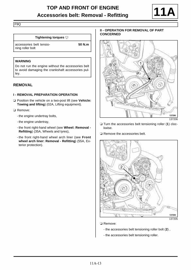
11A-13
TOP AND FRONT OF ENGINEAccessories belt: Removal - Refitting
F9Q
11A
REMOVAL
I - REMOVAL PREPARATION OPERATION
a Position the vehicle on a two-post lift (see Vehicle:Towing and lifting) (02A, Lifting equipment).
a Remove:
- the engine undertray bolts,
- the engine undertray,
- the front right-hand wheel (see Wheel: Removal -Refitting) (35A, Wheels and tyres),
- the front right-hand wheel arch liner (see Frontwheel arch liner: Removal - Refitting) (55A, Ex-terior protection).
II - OPERATION FOR REMOVAL OF PART CONCERNED
a Turn the accessories belt tensioning roller (1) cloc-kwise.
a Remove the accessories belt.
a Remove:
- the accessories belt tensioning roller bolt (2) ,
- the accessories belt tensioning roller.
Tightening torquesm
accessories belt tensio-ning roller bolt
50 N.m
WARNING
Do not run the engine without the accessories beltto avoid damaging the crankshaft accessories pul-ley.
137206
137205
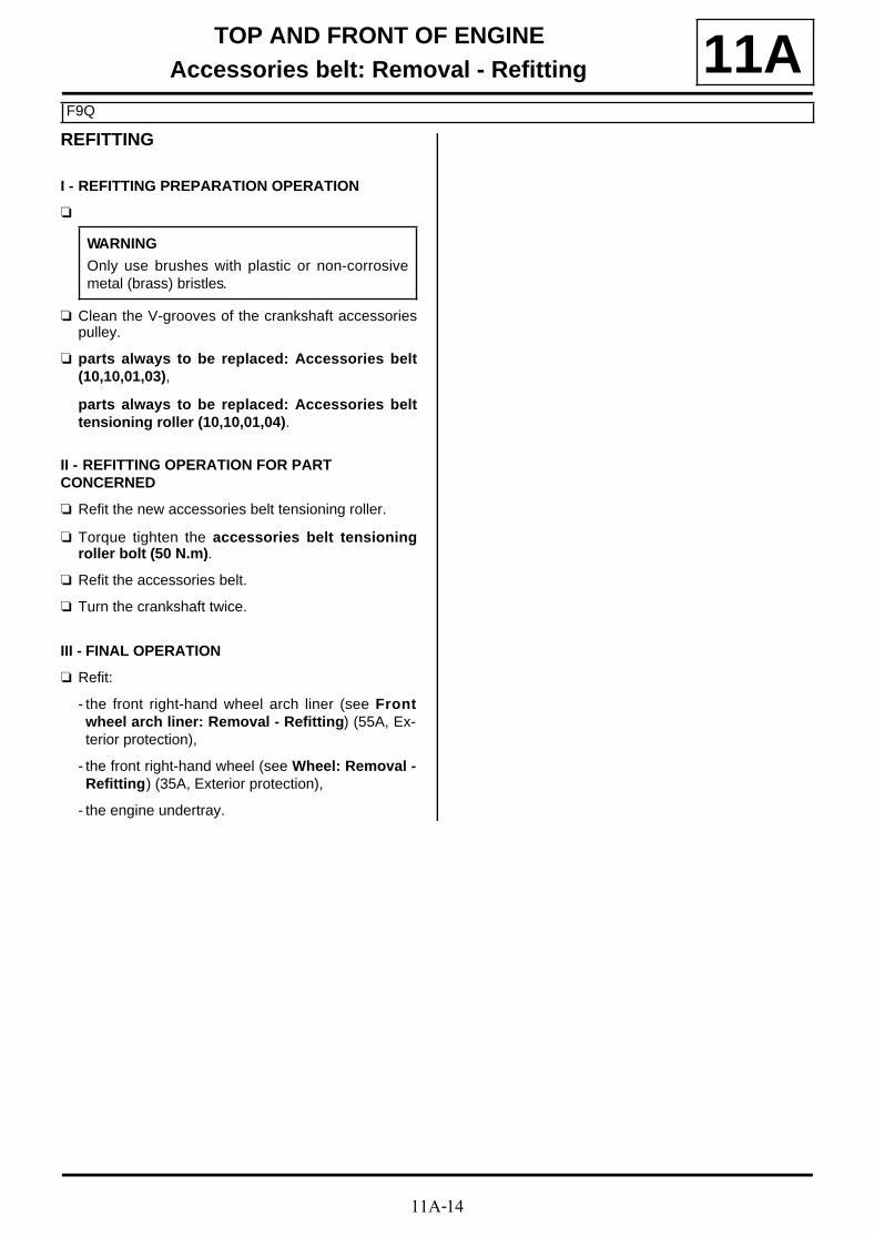
11A-14
TOP AND FRONT OF ENGINEAccessories belt: Removal - Refitting
F9Q
11AREFITTING
I - REFITTING PREPARATION OPERATION
a
a Clean the V-grooves of the crankshaft accessoriespulley.
a parts always to be replaced: Accessories belt(10,10,01,03),
parts always to be replaced: Accessories belttensioning roller (10,10,01,04).
II - REFITTING OPERATION FOR PART CONCERNED
a Refit the new accessories belt tensioning roller.
a Torque tighten the accessories belt tensioningroller bolt (50 N.m).
a Refit the accessories belt.
a Turn the crankshaft twice.
III - FINAL OPERATION
a Refit:
- the front right-hand wheel arch liner (see Frontwheel arch liner: Removal - Refitting) (55A, Ex-terior protection),
- the front right-hand wheel (see Wheel: Removal -Refitting) (35A, Exterior protection),
- the engine undertray.
WARNING
Only use brushes with plastic or non-corrosivemetal (brass) bristles.

11A-15
TOP AND FRONT OF ENGINECrankshaft accessories pulley: Removal - Refitting
K9K
11A
REMOVAL
I - REMOVAL PREPARATION OPERATION
a Position the vehicle on a two-post lift (see Vehicle:Towing and lifting) (02A, Lifting equipment).
a Remove:
- the engine cover,
- the front right-hand wheel (see Wheel: Removal -Refitting) (35A, Wheels and tyres),
- the front section of the front right-hand wheel archliner (see Front wheel arch liner: Removal - Re-fitting) (55A, Exterior protection),
- the engine undertray bolts,
- the engine undertray,
- the accessories belt (see 11A, Top and front ofengine, Accessories belt: Removal - Refitting,page 11A-7) .
II - OPERATION FOR REMOVAL OF PART CONCERNED
a Lock the flywheel using a screwdriver (1) .
Essential special tooling
Mot. 1489 TDC locating pin.
Tightening torquesm
crankshaft accessoriespulley bolt
120 N.m + 95˚±±±± 15˚
TDC pin plug 23 N.m
WARNING
Do not run the engine without the accessories beltto avoid damaging the crankshaft accessories pul-ley.
IMPORTANT
Wear protective gloves during the operation.
K9K, and 832
135405

11A-16
TOP AND FRONT OF ENGINECrankshaft accessories pulley: Removal - Refitting
K9K
11A
a Lock the flywheel using a screwdriver (1) .
a Remove:
- the crankshaft accessories pulley bolt (2) ,
- the crankshaft accessories pulley (3) .
REFITTING
I - REFITTING PREPARATION OPERATION
a parts always to be replaced: Crankshaft acces-sories pulley bolts (10,03,03,10).
a If reusing the crankshaft accessories pulley, cleanthe crankshaft accessories pulley V-grooves with abrush to eliminate any deposits.
a Refit the old crankshaft accessories pulley bolt (4)with a spacer (5) .
a Turn the crankshaft clockwise (timing end) using theold bolt of the crankshaft accessories pulley, untilthe collet of the crankshaft timing pinion (6) is almostvertical and facing upwards.
K9K, and 830 or 834
135413
135491
WARNING
Only use brushes with plastic or non-corrosivemetal (brass) bristles.
107272

11A-17
TOP AND FRONT OF ENGINECrankshaft accessories pulley: Removal - Refitting
K9K
11A
a Remove the TDC setting pin plug (7) .
a Screw tool (Mot. 1489) into the cylinder block.
a Remove the old bolt from the crankshaft accessoriespulley fitted with its spacer.
II - REFITTING OPERATION FOR PART CONCERNED
a Refit:
- the crankshaft accessories pulley,
- a new crankshaft accessories pulley bolt.
a Turn the crankshaft clockwise (timing end) smoothlyusing the bolt of the crankshaft accessories pulley,until the crankshaft presses against the tool (Mot.1489) (8) .
a Torque tighten the crankshaft accessories pulleybolt (120 N.m + 95˚ ±±±± 15 )̊.
III - FINAL OPERATION
a Remove the (Mot. 1489) from the cylinder block.
a Apply a drop of SILICONE ADHESIVE SEALANT(see Vehicle: Parts and ingredients for the repai-rwork) to the threading of the TDC pin plug.
a Tighten to torque the TDC pin plug (23 N.m).
a Refit:
- the accessories belt (see 11A, Top and front ofengine, Accessories belt: Removal - Refitting,page 11A-7) ,
- the engine undertray,
- the front section of the front right-hand wheel archliner (see Front wheel arch liner: Removal - Re-fitting) (55A, Exterior protection),
- the front right-hand wheel (see Wheel: Removal -Refitting) (35A, Wheels and tyres),
- the engine cover.
135472
135471
14489

11A-18
TOP AND FRONT OF ENGINECrankshaft accessories pulley: Removal - Refitting
F4R
11A
REMOVAL
I - REMOVAL PREPARATION OPERATION
a Position the vehicle on a two-post lift (see Vehicle:Towing and lifting) (02A, Lifting equipment).
a Remove:
- the front right-hand wheel (see Wheel: Removal -Refitting) (35A, Wheels and tyres),
- the front section of the front right-hand wheel archliner (see Front wheel arch liner: Removal - Re-fitting) (55A, Exterior protection),
- the accessories belt (see 11A, Top and front ofengine, Accessories belt: Removal - Refitting,page 11A-7) ,
- the engine undertray bolts,
- the engine undertray.
II - OPERATION FOR REMOVAL OF PART CONCERNED
a Immobilise the flywheel using a screwdriver or amale offset BTR wrench at (1) .
a Remove:
- the crankshaft accessories pulley bolt (2) ,
- the crankshaft accessories pulley.
Tightening torquesm
crankshaft accessoriespulley bolt
40 N.m + 110˚±±±± 10
IMPORTANT
Wear protective gloves during the operation.
WARNING
Do not run the engine without the accessories beltto avoid damaging the crankshaft accessories pul-ley.
123719
136604

11A-19
TOP AND FRONT OF ENGINECrankshaft accessories pulley: Removal - Refitting
F4R
11AREFITTING
I - REFITTING PREPARATION OPERATION
a parts always to be replaced: Crankshaft acces-sories pulley bolts (10,03,03,10).
a parts always to be replaced: Crankshaft acces-sories pulley (10,03,03,07).
II - REFITTING OPERATION FOR PART CONCERNED
a Refit:
- a new crankshaft accessories pulley,
- a new bolt on the crankshaft accessories pulley byimmobilising the engine using a screwdriver or amale offset BTR wrench.
a Torque tighten the crankshaft accessories pulleybolt (40 N.m + 110˚ ±±±± 10).
III - FINAL OPERATION
a Refit:
- the engine undertray,
- the accessories belt (see 11A, Top and front ofengine, Accessories belt: Removal - Refitting,page 11A-7) ,
- the front section of the front right-hand wheel archliner (see Front wheel arch liner: Removal - Re-fitting) (55A, Exterior protection),
- the front right-hand wheel (see Wheel: Removal -Refitting) (35A, Wheels and tyres).
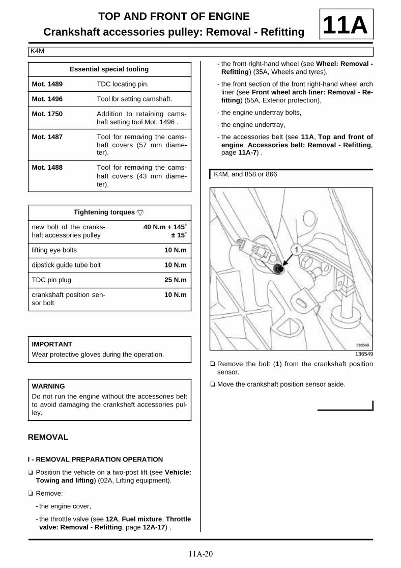
11A-20
TOP AND FRONT OF ENGINECrankshaft accessories pulley: Removal - Refitting
K4M
11A
REMOVAL
I - REMOVAL PREPARATION OPERATION
a Position the vehicle on a two-post lift (see Vehicle:Towing and lifting) (02A, Lifting equipment).
a Remove:
- the engine cover,
- the throttle valve (see 12A, Fuel mixture, Throttlevalve: Removal - Refitting, page 12A-17) ,
- the front right-hand wheel (see Wheel: Removal -Refitting) (35A, Wheels and tyres),
- the front section of the front right-hand wheel archliner (see Front wheel arch liner: Removal - Re-fitting) (55A, Exterior protection),
- the engine undertray bolts,
- the engine undertray,
- the accessories belt (see 11A, Top and front ofengine, Accessories belt: Removal - Refitting,page 11A-7) .
a Remove the bolt (1) from the crankshaft positionsensor.
a Move the crankshaft position sensor aside.
Essential special tooling
Mot. 1489 TDC locating pin.
Mot. 1496 Tool for setting camshaft.
Mot. 1750 Addition to retaining cams-haft setting tool Mot. 1496 .
Mot. 1487 Tool for removing the cams-haft covers (57 mm diame-ter).
Mot. 1488 Tool for removing the cams-haft covers (43 mm diame-ter).
Tightening torquesm
new bolt of the cranks-haft accessories pulley
40 N.m + 145˚±±±± 15˚
lifting eye bolts 10 N.m
dipstick guide tube bolt 10 N.m
TDC pin plug 25 N.m
crankshaft position sen-sor bolt
10 N.m
IMPORTANT
Wear protective gloves during the operation.
WARNING
Do not run the engine without the accessories beltto avoid damaging the crankshaft accessories pul-ley.
K4M, and 858 or 866
136549

11A-21
TOP AND FRONT OF ENGINECrankshaft accessories pulley: Removal - Refitting
K4M
11A
a Remove:
- the nut (2) securing the engine wiring on the liftingeye,
- the dipstick guide bolt (3) from the lifting eye.
a Unclip the engine wiring connector (4) from the liftingeye.
a Move aside the engine wiring.
a Remove the nut securing the engine wiring on the lif-ting eye.
a Unclip the engine wiring connector from the liftingeye.
a Remove:
- the lifting eye bolts (5) ,
- the lifting eye.
a Pierce the centre of the plugs (6) at the camshaftends with a screwdriver.
a Remove:
- the plugs from the camshaft ends with a screwdri-ver,
- the TDC setting pin plug (7) .
K4M, and 848
136454
K4M, and 858 or 866
135260
14491

11A-22
TOP AND FRONT OF ENGINECrankshaft accessories pulley: Removal - Refitting
K4M
11A
a Position the camshaft grooves (8) almost horizontal-ly and offset towards the bottom turning the cranks-haft in the operating direction (clockwise at timingend).
a Screw in the TDC setting pin (Mot. 1489) (9) .
a Turn the crankshaft in its operating direction (cloc-kwise at timing end), until the crankshaft pressesagainst the TDC setting pin (Mot. 1489).
a The camshaft grooves (10) must be horizontal andoffset downwards.
a Remove the TDC setting pin (Mot. 1489).
a Lock the flywheel using a screwdriver.
14491-1
14489
135905
K4M, and 848

11A-23
TOP AND FRONT OF ENGINECrankshaft accessories pulley: Removal - Refitting
K4M
11A
a Position an 8mm male offset Allen key or a ratchetextension piece in the crankshaft position sensor ho-le.
a Turn the engine slightly and smoothly to position theoffset key in the groove of a flywheel target tooth.
II - OPERATION FOR REMOVAL OF PART CONCERNED
a Remove:
- the crankshaft accessories pulley bolt (11) ,
- the crankshaft accessories pulley.
REFITTING
I - REFITTING PREPARATION OPERATION
a parts always to be replaced: Crankshaft acces-sories pulley bolts (10,10,01,11).
.
K4M, and 858 or 866
136543
WARNING
Failure to observe the following procedure maydamage the flywheel target and therefore preventthe engine from starting.
135907

11A-24
TOP AND FRONT OF ENGINECrankshaft accessories pulley: Removal - Refitting
K4M
11A
a Fit:
- the timing tool (Mot. 1496) (12) fitted with the (Mot.1750) (13) ,
- a lifting eye bolt (14) to secure the timing tool (Mot.1496) fitted with the (Mot. 1750).
a Screw in the TDC setting pin (Mot. 1489).
a Check that the crankshaft is pressing against theTDC setting pin.
a The crankshaft groove must be upwards.
a If the crankshaft is not pressing against the TDC set-ting pin, bring the crankshaft back by turning theflywheel using a screwdriver (15) .
135240
14489-2
K4M, and 848
135257

11A-25
TOP AND FRONT OF ENGINECrankshaft accessories pulley: Removal - Refitting
K4M
11A
a If the crankshaft is not pressing against the TDC set-ting pin, bring the crankshaft back by turning theflywheel using a ratchet extension piece or an 8 mmAllen key through the crankshaft position sensor ho-le.
II - REFITTING OPERATION FOR PART CONCERNED
a Refit the accessories crankshaft pulley with a newbolt.
a Torque tighten the new bolt of the crankshaft ac-cessories pulley (40 N.m + 145˚ ±±±± 15˚).
III - FINAL OPERATION
a Remove:
- the TDC setting pin (Mot. 1489),
- the lifting eye bolt from the timing tool (Mot. 1496)fitted with the (Mot. 1750),
- the timing tool (Mot. 1496) fitted with the (Mot.1750).
a Refit:
- the inlet camshaft plug using the (Mot. 1487),
- the exhaust camshaft plug using the (Mot. 1488),
- the lifting eye.
a Torque tighten the lifting eye bolts (10 N.m).
a Fit the engine wiring on the lifting eye.
a Clip the engine wiring connector on the lifting eye.
a Refit:
- the engine wiring retaining bolt on the lifting eye,
- the dipstick guide on the lifting eye.
a Torque tighten the dipstick guide tube bolt (10N.m).
a Refit the engine wiring nut on the lifting eye.
a Clip the engine wiring connector onto the lifting eye.
a Place a drop of SILICONE ADHESIVE SEALANT(see Vehicle: Parts and ingredients for the repai-rwork) (04B, Consumables - Products) on thethread of the TDC setting pin plug.
a Refit the TDC setting pin plug.
a Torque tighten the TDC pin plug (25 N.m).
a Fit the crankshaft position sensor.
a Refit the bolt on the crankshaft position sensor.
a Torque tighten the crankshaft position sensorbolt (10 N.m).
a Refit:
- the accessories belt (see 11A, Top and front ofengine, Accessories belt: Removal - Refitting,page 11A-7) ,
- the engine undertray,
- the front section of the front right-hand wheel archliner (see Front wheel arch liner: Removal - Re-fitting) (55A, Exterior protection),
- the front right-hand wheel (see Wheel: Removal -Refitting) (35A, Wheels and tyres),
- the throttle valve (see 12A, Fuel mixture, Throttlevalve: Removal - Refitting, page 12A-17) ,
K4M, and 858 or 866
136543
K4M, and 848
K4M, and 858 or 866
K4M, and 858 or 866
11A-26
TOP AND FRONT OF ENGINECrankshaft accessories pulley: Removal - Refitting
K4M
11A- the engine cover.

11A-27
TOP AND FRONT OF ENGINECrankshaft accessories pulley: Removal - Refitting
F9Q
11A
REMOVAL
I - REMOVAL PREPARATION OPERATION
a Position the vehicle on a two-post lift (see Vehicle:Towing and lifting) (02A, Lifting equipment).
a Remove:
- the engine undertray bolts,
- the engine undertray,
- the front right-hand wheel (see Wheel: Removal -Refitting) (35A, Wheels and tyres),
- the front right-hand wheel arch liner (see Frontwheel arch liner: Removal - Refitting) (55A, Ex-terior protection),
- the accessories belt (see 11A, Top and front ofengine, Accessories belt: Removal - Refitting,page 11A-7) .
a Remove the bolt (1) from the protective plate.
a Remove the protective plate.
a Lock the flywheel using a 30 torx screwdriver.
II - OPERATION FOR REMOVAL OF PART CONCERNED
a Remove:
- the crankshaft accessories pulley bolt (2) ,
- the crankshaft accessories pulley.
Essential equipment
brush with non abrasive bristles
Tightening torquesm
crankshaft accessoriespulley bolt
40 N.m + 110˚+/- 10˚
IMPORTANT
Wear protective gloves during the operation.
WARNING
Do not run the engine without the accessories beltto avoid damaging the crankshaft accessories pul-ley. 137199
137205
11A-28
TOP AND FRONT OF ENGINECrankshaft accessories pulley: Removal - Refitting
F9Q
11AREFITTING
I - REFITTING PREPARATION OPERATION
a parts always to be replaced: Crankshaft acces-sories pulley bolts (10,03,03,10).
a Clean the crankshaft accessories pulley V groovesusing a brush with non abrasive bristles if it is tobe reused.
II - REFITTING OPERATION FOR PART CONCERNED
a Refit the crankshaft accessories pulley.
a Lock the flywheel using a 30 torx screwdriver.
a Torque tighten the crankshaft accessories pulleybolt (40 N.m + 110˚ +/- 10˚).
III - FINAL OPERATION
a Refit:
- the protective plate,
- the accessories belt (see 11A, Top and front ofengine, Accessories belt: Removal - Refitting,page 11A-7) ,
- the front right-hand wheel arch liner (see Frontwheel arch liner: Removal - Refitting) (55A, Ex-terior protection),
- the front right-hand wheel (see Wheel: Removal -Refitting) (35A, Wheels and tyres),
- the engine undertray.
Note:
Only replace the crankshaft accessories pulleyduring general maintenance operations.

11A-29
TOP AND FRONT OF ENGINETiming belt: Removal - Refitting
K9K
11A
REMOVAL
I - REMOVAL PREPARATION OPERATION
a Position the vehicle on a two-post lift (see Vehicle:Towing and lifting) (02A, Lifting equipment).
a Disconnect the battery (see Battery : Removal -Refitting) (80A, Battery).
a Remove:
- the engine cover,
- the front right-hand wheel (see Wheel: Removal -Refitting) (35A, Wheels and tyres),
- the front section of the front right-hand wheel archliner (see Front wheel arch liner: Removal - Re-fitting) (55A, Exterior protection),
- the engine undertray bolts,
- the engine undertray,
- the accessories belt (see 11A, Top and front ofengine, Accessories belt: Removal - Refitting,page 11A-7) ,
- the crankshaft accessories pulley (see 11A, Topand front of engine, Crankshaft accessoriespulley: Removal - Refitting, page 11A-15) .
a Remove the lower engine tie-bar (see 19D, Enginemounting, Lower engine tie-bar: Removal - Refit-ting, page 19D-33) .
a Refit the old crankshaft accessories pulley bolt witha spacer (which does not cover the crankshaft timingsprocket mark) on the crankshaft.
a Remove:
- the windscreen wiper arms (see Windscreen wi-per arm: Removal - Refitting) (85A, Wiping -Washing),
- the scuttle panel grille (see Scuttle panel grille:Removal - Refitting) (56A, Exterior equipment),
- the scoop under the scuttle panel grille (see Scoopunder scuttle panel grille: Removal - Refitting)(56A, Exterior equipment),
- the right-hand suspended engine mounting (see19D, Engine mounting, Right-hand suspendedengine mounting: Removal - Refitting, page19D-18) .
Essential special tooling
Mot. 1489 TDC locating pin.
Mot. 1430 Set of 5 crankshaft and cams-haft pulley timing pins.
Essential equipment
offset spanner
Tightening torquesm
timing belt tensioningroller bolt
27 N.m
camshaft pulley hubbolts
14 N.m
new crankshaft acces-sories pulley bolt
120 N.m + 95 ±±±±15˚
TDC setting pin plug 25 N.m
K9K, and 830 or 834
107272

11A-30
TOP AND FRONT OF ENGINETiming belt: Removal - Refitting
K9K
11A
a Remove the camshaft position sensor (see 13B,Diesel injection, Camshaft position sensor: Re-moval - Refitting, page 13B-19) .
K9K, and 830

11A-31
TOP AND FRONT OF ENGINETiming belt: Removal - Refitting
K9K
11A
K9K, and 832
135495
135494
135493
135492

11A-32
TOP AND FRONT OF ENGINETiming belt: Removal - Refitting
K9K
11A
a Remove:
- the upper timing cover (1) by pressing on the clips(2) ,
- the bolt (3) from the intermediate timing cover (4) ,
- the intermediate timing cover (4) by pressing on theclips (5) ,
- the lower timing cover (6) by pressing on the clips(7) .
135475
135476
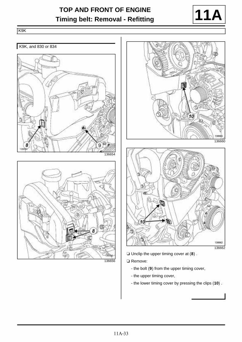
11A-33
TOP AND FRONT OF ENGINETiming belt: Removal - Refitting
K9K
11A
a Unclip the upper timing cover at (8) .
a Remove:
- the bolt (9) from the upper timing cover,
- the upper timing cover,
- the lower timing cover by pressing the clips (10) .
K9K, and 830 or 834
136654
136656
136660
136662
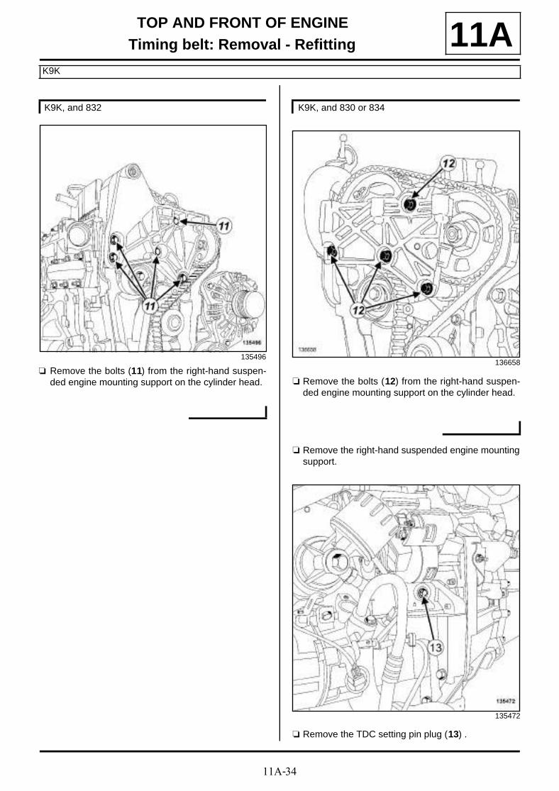
11A-34
TOP AND FRONT OF ENGINETiming belt: Removal - Refitting
K9K
11A
a Remove the bolts (11) from the right-hand suspen-ded engine mounting support on the cylinder head. a Remove the bolts (12) from the right-hand suspen-
ded engine mounting support on the cylinder head.
a Remove the right-hand suspended engine mountingsupport.
a Remove the TDC setting pin plug (13) .
K9K, and 832
135496
K9K, and 830 or 834
136658
135472

11A-35
TOP AND FRONT OF ENGINETiming belt: Removal - Refitting
K9K
11AII - OPERATION FOR REMOVAL OF PART CONCERNED
a Turn the crankshaft clockwise (timing end) using theold crankshaft accessories pulley bolt and its spacerto position the hole (14) of the camshaft pulley hubalmost opposite the hole (15) in the cylinder head.
a Screw tool (Mot. 1489) (16) into the cylinder block.
a Turn the crankshaft clockwise (timing end) smoothlyuntil the crankshaft comes in contact with the (Mot.1489).
a Insert the tool (Mot. 1430) (17) in the holes of thecamshaft pulley hub and the hole of the cylinderhead.
107270
135471
14489-1
109049

11A-36
TOP AND FRONT OF ENGINETiming belt: Removal - Refitting
K9K
11A
a Undo the timing belt tensioning roller bolt (18) .
a Loosen the timing belt tensioning roller by turningthe eccentric cam using a 6 mm Allen key.
a Remove:
- the timing belt,
- the timing belt tensioning roller bolt,
- the timing belt tensioning roller.
REFITTING
I - REFITTING PREPARATION OPERATION
a parts always to be replaced: Timing belt (10,02,04,02).
a parts always to be replaced: Timing belt tensio-ning roller (10,02,04,04).
a parts always to be replaced: Crankshaft acces-sories pulley bolts (10,03,03,10).
a Always replace the timing belt tensioning roller bolt.
II - REFITTING OPERATION FOR PART CONCERNED
a Refit the new timing belt tensioning roller.
a Fit the timing belt tensioning roller lug (19) in the cy-linder head groove (20) .
a Check that:
- the mark (22) on the high-pressure pump is offsetby one tooth to the right of the vertical axis (23) ,
109046
K9K, and 832
109042
109043

11A-37
TOP AND FRONT OF ENGINETiming belt: Removal - Refitting
K9K
11A- the crankshaft is resting on the tool (Mot. 1489)(the cotter (24) of the crankshaft timing sprocketmust be vertical and upwards).
a Refit the new timing belt tensioning roller.
a Fit the timing belt tensioning roller lug (25) in the cy-linder head groove (26) .
a Check that:
- Check that the mark (28) on the high pressurepump is opposite the bolt head (29) .
K9K, and 830 or 834
136389
109043

11A-38
TOP AND FRONT OF ENGINETiming belt: Removal - Refitting
K9K
11A- the crankshaft is resting on the tool (Mot. 1489)(the cotter (30) of the crankshaft timing sprocketupwards).
a Check that the crankshaft is resting on the tool (Mot.1489) while turning the crankshaft clockwise usingthe old crankshaft accessories pulley bolt and itsspacer.
a Remove the bolt (31) from the camshaft pulley hub.
a Loosen the other bolts of the camshaft pulley hub byone turn.
14489
109049

11A-39
TOP AND FRONT OF ENGINETiming belt: Removal - Refitting
K9K
11A
a Fit the new timing belt starting with the crankshaftsprocket.
a Align the timing belt marks with the marks:
- of the crankshaft timing sprocket,
- of the camshaft pulley,
- of the high pressure pump pulley.
a Bring the timing belt tensioning roller adjustable in-dex (32) opposite the lug (33) using a 6 mm Allenkey, turning it anti-clockwise.
a Tighten the timing belt tensioning roller bolt.
109044
Note:
There should be 19 timing belt tooth groovesbetween the marks on the camshaft pulley andthe high pressure pump pulley and 51 timing belttooth grooves between the marks on the cranks-haft timing sprocket and the high pressure pumppulley.
19658

11A-40
TOP AND FRONT OF ENGINETiming belt: Removal - Refitting
K9K
11A
a
109047
Note:
Check that the camshaft pulley hub bolts are notfully up against the camshaft pulley wheel.

11A-41
TOP AND FRONT OF ENGINETiming belt: Removal - Refitting
K9K
11A
a Refit the camshaft pulley hub lower bolt (34) .
a Tighten the camshaft pulley hub bolts.
a Remove:
- the (Mot. 1489),
- the (Mot. 1430).
109045

11A-42
TOP AND FRONT OF ENGINETiming belt: Removal - Refitting
K9K
11A
a Turn the crankshaft two turns clockwise (timing end) using the old crankshaft accessories pulley bolt and its spacer until the hole (35) of the camshaft pulley hub is opposite the hole (36) in the cylinder head:
- screw tool (Mot. 1489) into the cylinder block,
- turn the crankshaft clockwise (timing end) smoothlyusing the old crankshaft accessories pulley boltand its spacer, until the crankshaft comes into con-tact with the (Mot. 1489).
a Set the camshaft pulley hub using the tool (Mot.1430) (37) .
a
a Loosen the camshaft pulley hub bolts by one turn.
107270
109049
109048
Note:
If the tool (Mot. 1430) does not engage correctly:
-loosen the camshaft pulley hub bolts by up toone turn,
-turn the camshaft pulley hub using an 18mmoffset spanner to set the camshaft pulley hub,
-do not retighten the camshaft pulley hub bolts.
Note:
After the two turns, the adjustable index of thetensioning roller may be in two different positions.
The rotation of the tension wheel eccentricdepends on the position.

11A-43
TOP AND FRONT OF ENGINETiming belt: Removal - Refitting
K9K
11AFirst position of the index of the timing belt tensioning roller
a Loosen the timing belt tensioning roller bolt by up toone turn while holding the adjustable index with a 6mm Allen key.
a Gradually align the adjustable index of the timingbelt tensioning roller in the middle of the timing win-dow by turning the key anticlockwise.
Second position of the adjustable index of the timing belt tensioning roller
a Loosen the timing belt tensioning roller bolt by up toone turn while holding the adjustable index with a 6mm Allen key.
a Gradually position the adjustable index of the timingbelt tensioning roller in the middle of the timing win-dow by turning the key clockwise.
a Tighten to torque:
- the timing belt tensioning roller bolt (27 N.m),
- the camshaft pulley hub bolts (14 N.m).
111083
111081
111082
111081

11A-44
TOP AND FRONT OF ENGINETiming belt: Removal - Refitting
K9K
11Aa Remove:
- the (Mot. 1489),
- the (Mot. 1430).
a Turn the crankshaft two turns clockwise (timing end)using the old crankshaft accessories pulley bolt andits spacer until the hole of the camshaft pulley hub isopposite the hole in the cylinder head.
a Screw tool (Mot. 1489) into the cylinder block.
a Turn the crankshaft clockwise (timing end) smoothlyusing the old crankshaft accessories pulley bolt andits spacer, until the crankshaft comes into contactwith the tool (Mot. 1489).
a Set the camshaft pulley hub using the tool (Mot.1430).
a If the tool (Mot. 1430) does not engage, repeat thetiming belt refitting operation.
III - FINAL OPERATION
a Refit the right-hand suspended mounting support.
a Refit the lower timing cover by positioning the lowertiming cover tab in the inner cover opening.
a Clip on the lower timing cover.
a Refit the intermediate timing cover.
a Clip on the intermediate timing cover.
a Refit:
- the intermediate timing cover bolt,
- the upper timing cover.
a Clip on the upper timing cover.
a Clip on the lower timing cover.
a Refit:
- the upper timing cover,
- the upper timing cover bolt.
a Clip on the upper timing cover.
109049
123839
K9K, and 832
K9K, and 830 or 834
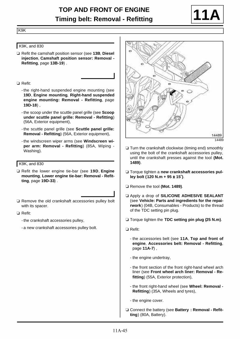
11A-45
TOP AND FRONT OF ENGINETiming belt: Removal - Refitting
K9K
11A
a Refit the camshaft position sensor (see 13B, Dieselinjection, Camshaft position sensor: Removal -Refitting, page 13B-19) .
a Refit:
- the right-hand suspended engine mounting (see19D, Engine mounting, Right-hand suspendedengine mounting: Removal - Refitting, page19D-18) ,
- the scoop under the scuttle panel grille (see Scoopunder scuttle panel grille: Removal - Refitting)(56A, Exterior equipment),
- the scuttle panel grille (see Scuttle panel grille:Removal - Refitting) (56A, Exterior equipment),
- the windscreen wiper arms (see Windscreen wi-per arm: Removal - Refitting) (85A, Wiping -Washing).
a Refit the lower engine tie-bar (see 19D, Enginemounting, Lower engine tie-bar: Removal - Refit-ting, page 19D-33) .
a Remove the old crankshaft accessories pulley boltwith its spacer.
a Refit:
- the crankshaft accessories pulley,
- a new crankshaft accessories pulley bolt.
a Turn the crankshaft clockwise (timing end) smoothlyusing the bolt of the crankshaft accessories pulley,until the crankshaft presses against the tool (Mot.1489).
a Torque tighten a new crankshaft accessories pul-ley bolt (120 N.m + 95 ±±±± 15˚).
a Remove the tool (Mot. 1489).
a Apply a drop of SILICONE ADHESIVE SEALANT(see Vehicle: Parts and ingredients for the repai-rwork) (04B, Consumables - Products) to the threadof the TDC setting pin plug.
a Torque tighten the TDC setting pin plug (25 N.m).
a Refit:
- the accessories belt (see 11A, Top and front ofengine, Accessories belt: Removal - Refitting,page 11A-7) ,
- the engine undertray,
- the front section of the front right-hand wheel archliner (see Front wheel arch liner: Removal - Re-fitting) (55A, Exterior protection),
- the front right-hand wheel (see Wheel: Removal -Refitting) (35A, Wheels and tyres),
- the engine cover.
a Connect the battery (see Battery : Removal - Refit-ting) (80A, Battery).
K9K, and 830
K9K, and 830
14489

11A-46
TOP AND FRONT OF ENGINETiming belt: Removal - Refitting
F9Q
11A
REMOVAL
I - REMOVAL PREPARATION OPERATION
a Position the vehicle on a two-post lift (see Vehicle:Towing and lifting) (02A, Lifting equipment).
a Disconnect the battery (see Battery : Removal -Refitting) (80A, Battery).
a Remove:
- the engine cover,
- the scuttle panel grille (see Scuttle panel grille:Removal - Refitting) (56A, Exterior equipment),
- the scoop under the scuttle panel grille (see Scoopunder scuttle panel grille: Removal - Refitting)(56A, Exterior equipment),
- the engine undertray bolts,
- the engine undertray,
- the front right-hand wheel (see Wheel: Removal -Refitting) (35A, Wheels and tyres),
- the front right-hand wheel arch liner (see Frontwheel arch liner: Removal - Refitting) (55A, Ex-terior protection),
- the accessories belt (see 11A, Top and front ofengine, Accessories belt: Removal - Refitting,page 11A-7) ,
- the crankshaft accessories pulley (see 11A, Topand front of engine, Crankshaft accessoriespulley: Removal - Refitting, page 11A-15) ,
- the lower engine tie-bar (see 19D, Engine moun-ting, Lower engine tie-bar: Removal - Refitting,page 19D-33) ,
- the right-hand suspended engine mounting (see19D, Engine mounting, Right-hand suspendedengine mounting: Removal - Refitting, page19D-18) .
a Remove:
- the timing cover bolts (1) ,
- the timing cover.
Adjusting the timing
a Remove the TDC setting pin plug (2) .
a Fit the (Mot. 1054) without inserting it fully.
Essential special tooling
Mot. 1054 TDC setting pin.
Tightening torquesm
timing tensioning rollerbolts
10 N.m
timing tensioning rollernut
25 N.m
TDC pin plug 25 N.m
137204
15102

11A-47
TOP AND FRONT OF ENGINETiming belt: Removal - Refitting
F9Q
11A
a Rotate the crankshaft in a clockwise direction at thetiming end.
a Bring the camshaft pulley mark to half a tooth beforethe mark on the inner timing cover.
a Push the TDC setting pin (Mot. 1054).
a Turn the crankshaft clockwise (timing end) until thecrankshaft is set.
a The camshaft pulley mark should be aligned with theinner timing cover mark.
II - OPERATION FOR REMOVAL OF PART CONCERNED
a Remove:
- the bolts (3) of the high pressure pump supportbracket,
- the high pressure pump support bracket.
a Undo the timing tension wheel nut (4) .
a Remove the timing belt.
104329
104330
137203
137201

11A-48
TOP AND FRONT OF ENGINETiming belt: Removal - Refitting
F9Q
11A
a Remove:
- the bolts (5) of the timing tensioning roller,
- the timing tensioning roller.
REFITTING
I - REFITTING PREPARATION OPERATION
a parts always to be replaced: Timing belt (10,02,04,02),
parts always to be replaced: Timing belt tensio-ning roller (10,02,04,04).
II - REFITTING OPERATION FOR PART CONCERNED
a Refit:
- the new timing belt tensioning roller,
- a new timing belt.
a Torque tighten the timing tensioning roller bolts(10 N.m).
a Using a Torx wrench, bring the adjustable index (6)opposite the mark (7) by turning the eccentric (8)anti-clockwise.
a Torque tighten the timing tensioning roller nut (25N.m)
a Remove the tool (Mot. 1054).
a Rotate the crankshaft clockwise through four revolu-tions.
a Check that the adjustable index (6) is opposite the mark (7) , if this is not the case:
- loosen the timing tensioning roller nut by up to oneturn while holding the eccentric with a Torx wrench,
- gradually move the adjustable index (6) oppositethe mark (7) by turning the eccentric (8) clockwise.
137200 137202
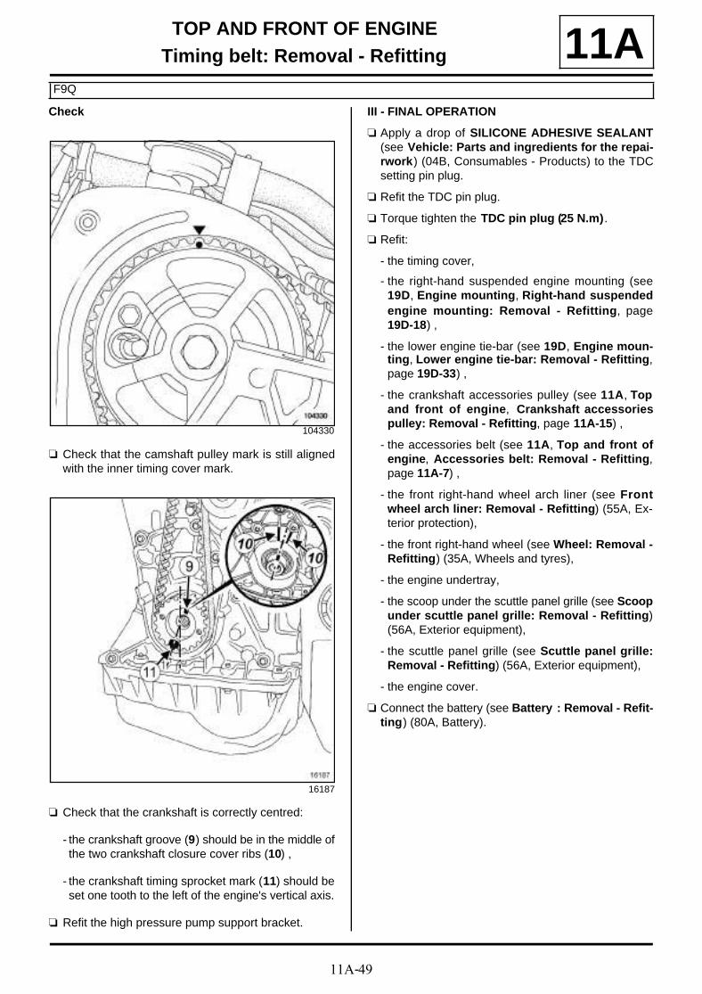
11A-49
TOP AND FRONT OF ENGINETiming belt: Removal - Refitting
F9Q
11ACheck
a Check that the camshaft pulley mark is still alignedwith the inner timing cover mark.
a Check that the crankshaft is correctly centred:
- the crankshaft groove (9) should be in the middle ofthe two crankshaft closure cover ribs (10) ,
- the crankshaft timing sprocket mark (11) should beset one tooth to the left of the engine's vertical axis.
a Refit the high pressure pump support bracket.
III - FINAL OPERATION
a Apply a drop of SILICONE ADHESIVE SEALANT(see Vehicle: Parts and ingredients for the repai-rwork) (04B, Consumables - Products) to the TDCsetting pin plug.
a Refit the TDC pin plug.
a Torque tighten the TDC pin plug (25 N.m).
a Refit:
- the timing cover,
- the right-hand suspended engine mounting (see19D, Engine mounting, Right-hand suspendedengine mounting: Removal - Refitting, page19D-18) ,
- the lower engine tie-bar (see 19D, Engine moun-ting, Lower engine tie-bar: Removal - Refitting,page 19D-33) ,
- the crankshaft accessories pulley (see 11A, Topand front of engine, Crankshaft accessoriespulley: Removal - Refitting, page 11A-15) ,
- the accessories belt (see 11A, Top and front ofengine, Accessories belt: Removal - Refitting,page 11A-7) ,
- the front right-hand wheel arch liner (see Frontwheel arch liner: Removal - Refitting) (55A, Ex-terior protection),
- the front right-hand wheel (see Wheel: Removal -Refitting) (35A, Wheels and tyres),
- the engine undertray,
- the scoop under the scuttle panel grille (see Scoopunder scuttle panel grille: Removal - Refitting)(56A, Exterior equipment),
- the scuttle panel grille (see Scuttle panel grille:Removal - Refitting) (56A, Exterior equipment),
- the engine cover.
a Connect the battery (see Battery : Removal - Refit-ting) (80A, Battery).
104330
16187
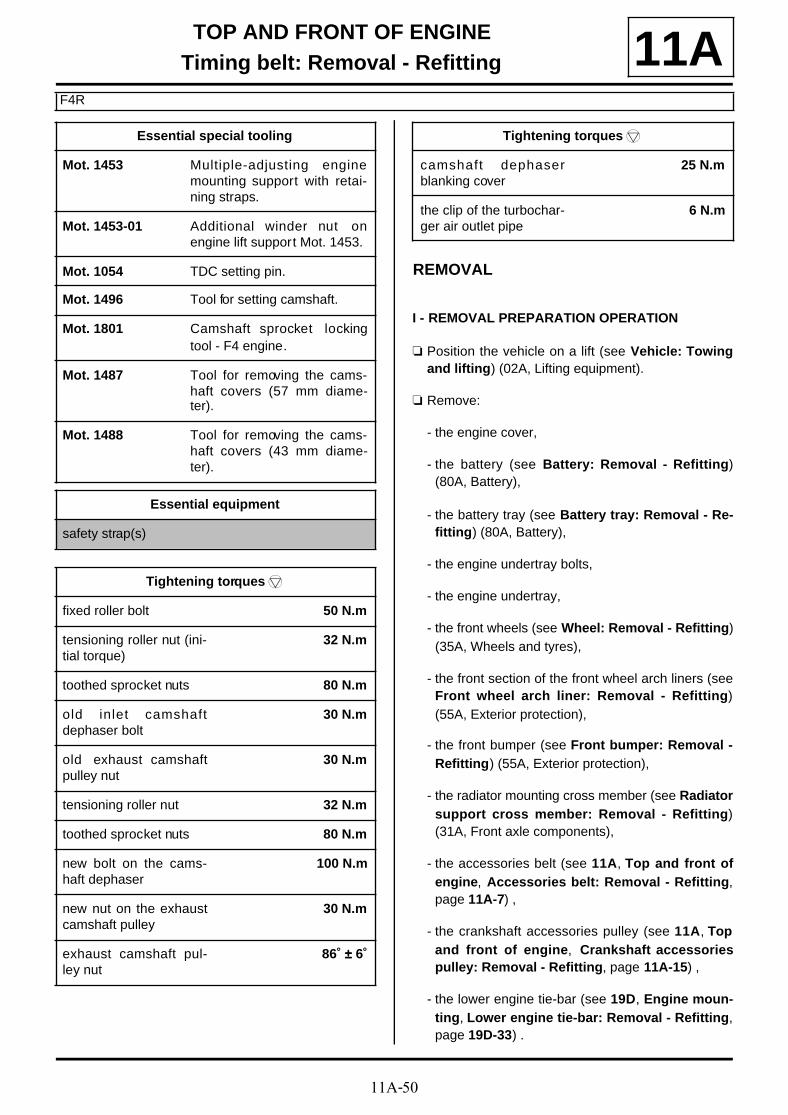
11A-50
TOP AND FRONT OF ENGINETiming belt: Removal - Refitting
F4R
11A
REMOVAL
I - REMOVAL PREPARATION OPERATION
a Position the vehicle on a lift (see Vehicle: Towingand lifting) (02A, Lifting equipment).
a Remove:
- the engine cover,
- the battery (see Battery: Removal - Refitting)(80A, Battery),
- the battery tray (see Battery tray: Removal - Re-fitting) (80A, Battery),
- the engine undertray bolts,
- the engine undertray,
- the front wheels (see Wheel: Removal - Refitting)(35A, Wheels and tyres),
- the front section of the front wheel arch liners (seeFront wheel arch liner: Removal - Refitting)(55A, Exterior protection),
- the front bumper (see Front bumper: Removal -Refitting) (55A, Exterior protection),
- the radiator mounting cross member (see Radiatorsupport cross member: Removal - Refitting)(31A, Front axle components),
- the accessories belt (see 11A, Top and front ofengine, Accessories belt: Removal - Refitting,page 11A-7) ,
- the crankshaft accessories pulley (see 11A, Topand front of engine, Crankshaft accessoriespulley: Removal - Refitting, page 11A-15) ,
- the lower engine tie-bar (see 19D, Engine moun-ting, Lower engine tie-bar: Removal - Refitting,page 19D-33) .
Essential special tooling
Mot. 1453 Multiple-adjusting enginemounting support with retai-ning straps.
Mot. 1453-01 Additional winder nut onengine lift support Mot. 1453.
Mot. 1054 TDC setting pin.
Mot. 1496 Tool for setting camshaft.
Mot. 1801 Camshaft sprocket lockingtool - F4 engine.
Mot. 1487 Tool for removing the cams-haft covers (57 mm diame-ter).
Mot. 1488 Tool for removing the cams-haft covers (43 mm diame-ter).
Essential equipment
safety strap(s)
Tightening torquesm
fixed roller bolt 50 N.m
tensioning roller nut (ini-tial torque)
32 N.m
toothed sprocket nuts 80 N.m
old inlet camshaftdephaser bolt
30 N.m
old exhaust camshaftpulley nut
30 N.m
tensioning roller nut 32 N.m
toothed sprocket nuts 80 N.m
new bolt on the cams-haft dephaser
100 N.m
new nut on the exhaustcamshaft pulley
30 N.m
exhaust camshaft pul-ley nut
86˚ ±±±± 6˚
camshaft dephaserblanking cover
25 N.m
the clip of the turbochar-ger air outlet pipe
6 N.m
Tightening torquesm

11A-51
TOP AND FRONT OF ENGINETiming belt: Removal - Refitting
F4R
11A
a Remove the clips (1) from the electric coolant pump(2) .
a Move aside the electric coolant pump.
a Remove:
- the nuts (3) from the exhaust connecting hose,
- the rubber mounting bush retaining bolt (4) fromthe exhaust hose,
- the connecting hose seal.
a Move aside the connecting hose.
a Remove:
- the windscreen wiper arms (see Windscreen wi-per arm: Removal - Refitting) (85A, Wiping -Washing),
135754 136595
137150

11A-52
TOP AND FRONT OF ENGINETiming belt: Removal - Refitting
F4R
11A- the scuttle panel grille (see Scuttle panel grille:Removal - Refitting) (56A, Exterior equipment),
- the scoop under the scuttle panel grille (see Scoopunder scuttle panel grille: Removal - Refitting)(56A, Exterior equipment).
a Disconnect:
- the pipe (5) on the petrol vapour rebreathing sole-noid valve,
- the fuel supply pipe (6) on the injector rail,
- the petrol vapour rebreathing pipe at (7) .
a Insert the blanking plugs.
a Unclip the pipes on the right-hand suspended engi-ne mounting cover.
134645
135779
WARNING
To prevent impurities from entering the circuit,place protective plugs on all fuel circuit compo-nents exposed to the open air.

11A-53
TOP AND FRONT OF ENGINETiming belt: Removal - Refitting
F4R
11A
a Remove:
- the bolt (8) from the air pipe on the intake distribu-tor,
- the retaining bracket bolts (9) on the turbochargerair outlet pipe.
a Loosen the clip (10) on the intercooler outlet air pipe.
a Disconnect the turbocharger air outlet pipe.
a Move aside the turbocharger air outlet pipe.
a Remove the plug (11) from the TDC setting pin.
135746
138084
134647
120211

11A-54
TOP AND FRONT OF ENGINETiming belt: Removal - Refitting
F4R
11A
a Remove the nut (12) from the engine wiring on thegearbox side lifting eye.
a Move aside the engine wiring.
a Remove:
- the gearbox side lifting eye bolts (13) ,
- the gearbox side lifting eye.
a Unclip the turbocharger vacuum pipe clip (14) .
a Disconnect the vacuum pipe from the turbocharger.
a Pierce the centre of the plugs (15) at the camshaftends with a screwdriver.
a Remove the caps from the camshaft ends with ascrewdriver.
134650
15105
138084
138084
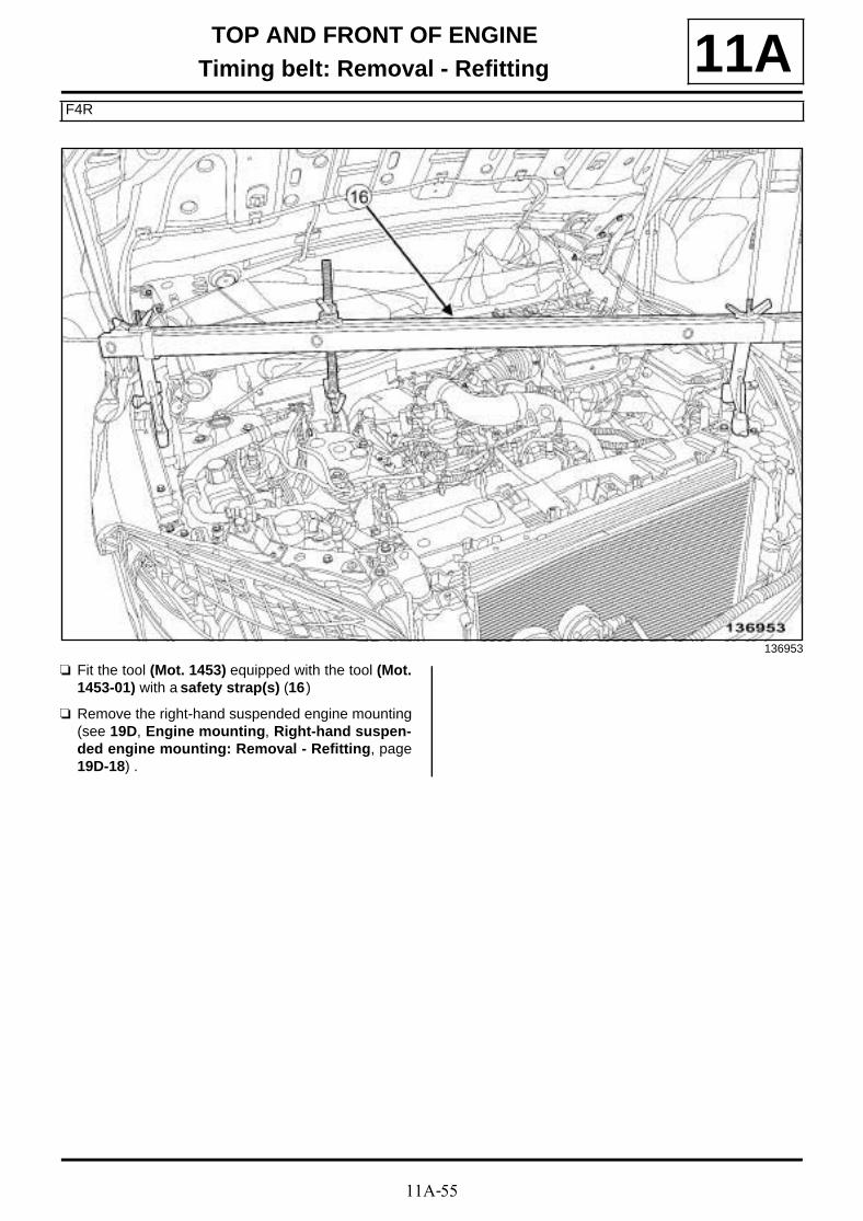
11A-55
TOP AND FRONT OF ENGINETiming belt: Removal - Refitting
F4R
11A
a Fit the tool (Mot. 1453) equipped with the tool (Mot.1453-01) with a safety strap(s) (16)
a Remove the right-hand suspended engine mounting(see 19D, Engine mounting, Right-hand suspen-ded engine mounting: Removal - Refitting, page19D-18) .
136953
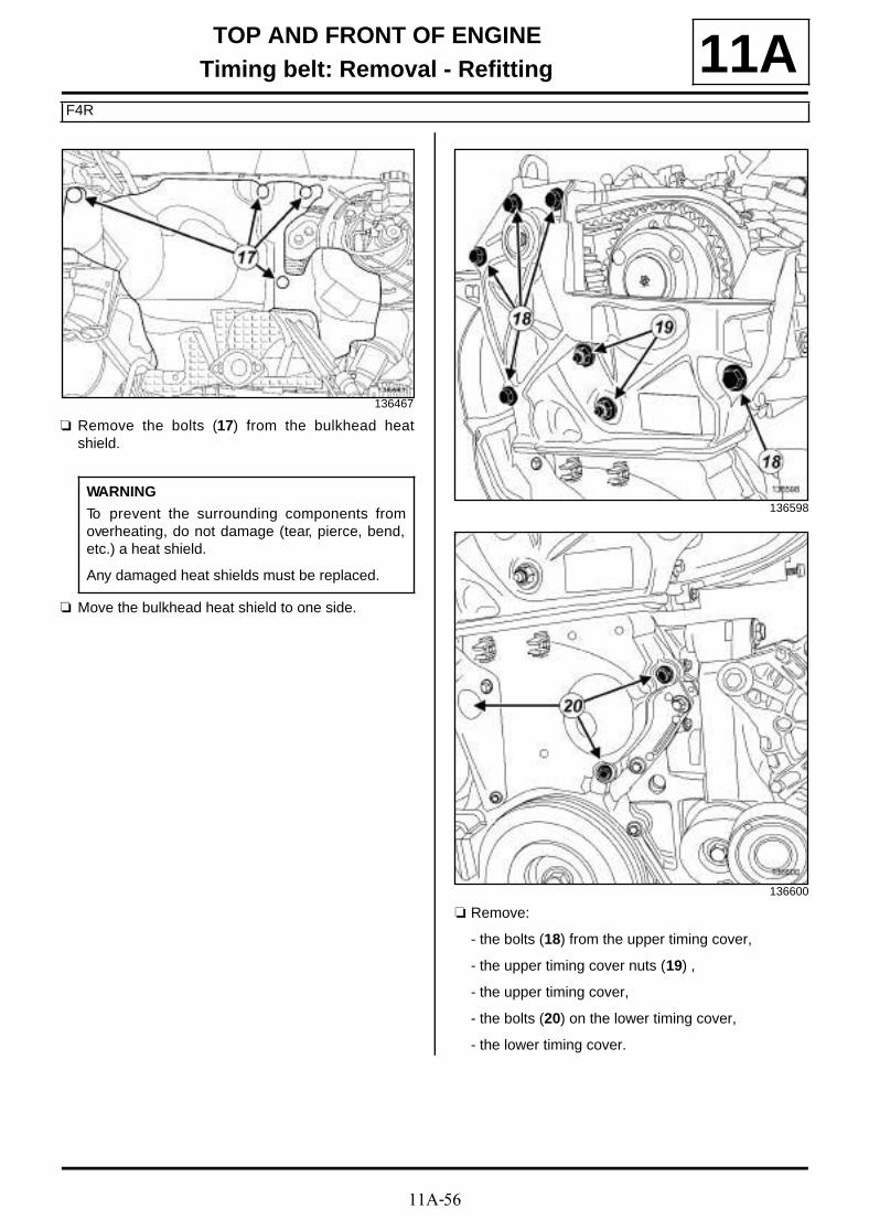
11A-56
TOP AND FRONT OF ENGINETiming belt: Removal - Refitting
F4R
11A
a Remove the bolts (17) from the bulkhead heatshield.
a Move the bulkhead heat shield to one side.
a Remove:
- the bolts (18) from the upper timing cover,
- the upper timing cover nuts (19) ,
- the upper timing cover,
- the bolts (20) on the lower timing cover,
- the lower timing cover.
136467
WARNING
To prevent the surrounding components fromoverheating, do not damage (tear, pierce, bend,etc.) a heat shield.
Any damaged heat shields must be replaced.
136598
136600

11A-57
TOP AND FRONT OF ENGINETiming belt: Removal - Refitting
F4R
11AII - OPERATION FOR REMOVAL OF PART CONCERNED
Adjusting the timing
a Refit:
- the crankshaft accessories pulley,
- the crankshaft accessories pulley bolt.
a Rotate the engine clockwise (timing end) so that thecamshaft grooves are offset below the centre lineand almost horizontal.
Position of TDC pin before setting point
Position of TDC pin setting point
a Insert the TDC setting pin (Mot. 1054) and rotate theengine slightly clockwise (timing end) until the set-ting point is reached.
15106
15163-2
15163-1

11A-58
TOP AND FRONT OF ENGINETiming belt: Removal - Refitting
F4R
11A
a At the setting point the camshaft grooves must behorizontal and offset below the centre line.
a Position the (Mot. 1496) (21) on the ends of thecamshafts.
a Lock the (Mot. 1496) using a bolt (22) .
a Remove:
- the crankshaft accessories pulley bolt,
- the crankshaft accessories pulley.
a Slacken the timing belt by undoing the tensioningroller nut (23) .
a Remove:
- the tensioning roller nut,
- the tensioning roller,
- the fixed roller bolt (24) ,
- the fixed roller and its spacer,
- the timing belt,
- the crankshaft timing sprocket.
15106-1
21880
136603
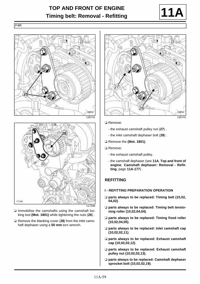
11A-59
TOP AND FRONT OF ENGINETiming belt: Removal - Refitting
F4R
11A
a Immobilise the camshafts using the camshaft loc-king tool (Mot. 1801) while tightening the nuts (26) .
a Remove the blanking cover (26) from the inlet cams-haft dephaser using a 50 mm torx wrench.
a Remove:
- the exhaust camshaft pulley nut (27) ,
- the inlet camshaft dephaser bolt (28) .
a Remove the (Mot. 1801).
a Remove:
- the exhaust camshaft pulley.
- the camshaft dephaser (see 11A, Top and front ofengine, Camshaft dephaser: Removal - Refit-ting, page 11A-177) .
REFITTING
I - REFITTING PREPARATION OPERATION
a parts always to be replaced: Timing belt (10,02,04,02).
a parts always to be replaced: Timing belt tensio-ning roller (10,02,04,04).
a parts always to be replaced: Timing fixed roller(10,02,04,05).
a parts always to be replaced: Inlet camshaft cap(10,02,02,11).
a parts always to be replaced: Exhaust camshaftcap (10,02,02,12).
a parts always to be replaced: Exhaust camshaftpulley nut (10,02,02,13).
a parts always to be replaced: Camshaft dephasersprocket bolt (10,02,02,19).
135741
117346
135741
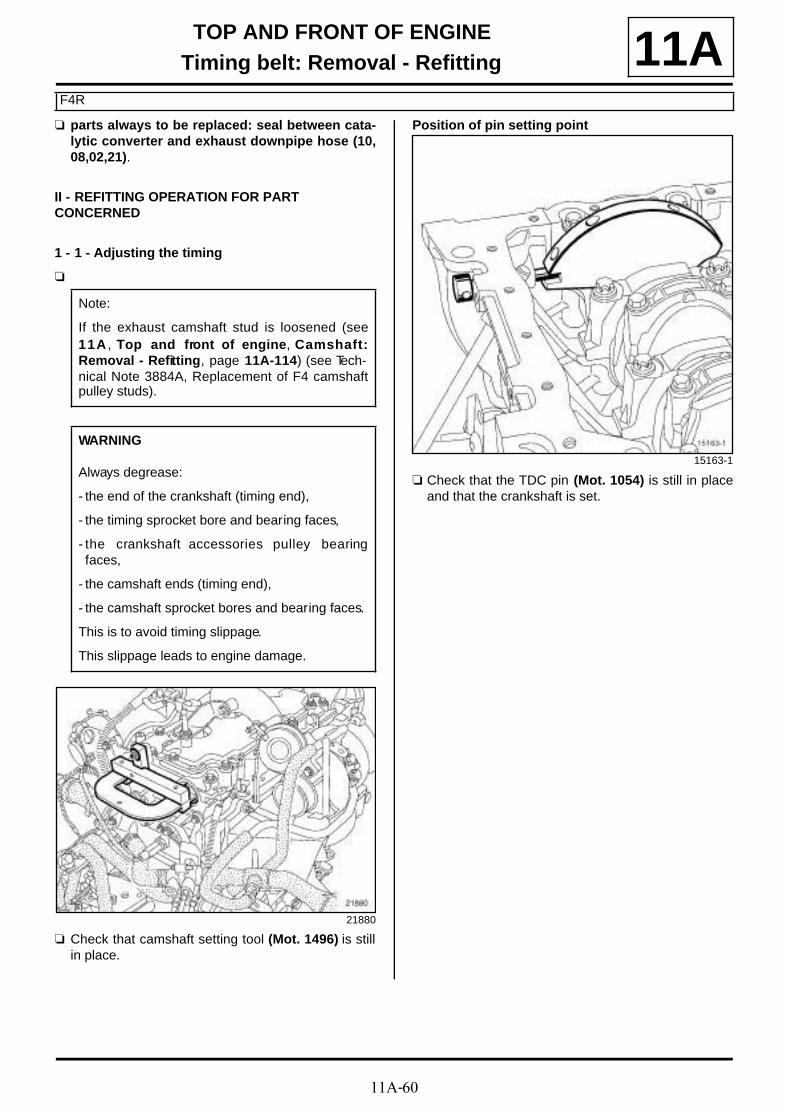
11A-60
TOP AND FRONT OF ENGINETiming belt: Removal - Refitting
F4R
11Aa parts always to be replaced: seal between cata-
lytic converter and exhaust downpipe hose (10,08,02,21).
II - REFITTING OPERATION FOR PART CONCERNED
1 - 1 - Adjusting the timing
a
a Check that camshaft setting tool (Mot. 1496) is stillin place.
Position of pin setting point
a Check that the TDC pin (Mot. 1054) is still in placeand that the crankshaft is set.
Note:
If the exhaust camshaft stud is loosened (see11A , Top and front of engine, Camshaft:Removal - Refitting, page 11A-114) (see Tech-nical Note 3884A, Replacement of F4 camshaftpulley studs).
WARNING
Always degrease:
- the end of the crankshaft (timing end),
- the timing sprocket bore and bearing faces,
- the crankshaft accessories pulley bearingfaces,
- the camshaft ends (timing end),
- the camshaft sprocket bores and bearing faces.
This is to avoid timing slippage.
This slippage leads to engine damage.
21880
15163-1

11A-61
TOP AND FRONT OF ENGINETiming belt: Removal - Refitting
F4R
11A
a
2 - Refitting the timing belt
a Refit the timing sprocket to the crankshaft.
a Refit:
- the inlet camshaft dephaser,
- the inlet camshaft dephaser bolt,
- the exhaust camshaft pulley.
- the exhaust camshaft pulley nut,
- a new tensioning roller, ensuring that the lug (29) ispositioned in the groove (30) ,
- the tensioning roller nut,
- a new timing belt,
- the new fixed roller with its spacer,
- the fixed roller bolt.
a Torque tighten the fixed roller bolt (50 N.m).
104703
WARNING
Always degrease:
- the end of the crankshaft (timing end),
- the timing sprocket bore and bearing faces,
- the contact surfaces of the crankshaft accesso-ries pulley.
This is to avoid timing slippage.
This slippage leads to engine damage.
15201
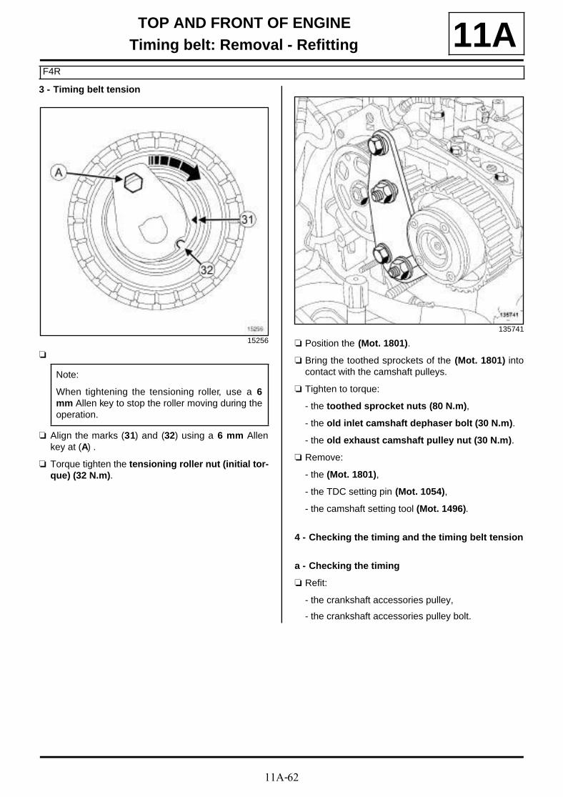
11A-62
TOP AND FRONT OF ENGINETiming belt: Removal - Refitting
F4R
11A3 - Timing belt tension
a
a Align the marks (31) and (32) using a 6 mm Allenkey at (A) .
a Torque tighten the tensioning roller nut (initial tor-que) (32 N.m).
a Position the (Mot. 1801).
a Bring the toothed sprockets of the (Mot. 1801) intocontact with the camshaft pulleys.
a Tighten to torque:
- the toothed sprocket nuts (80 N.m),
- the old inlet camshaft dephaser bolt (30 N.m).
- the old exhaust camshaft pulley nut (30 N.m).
a Remove:
- the (Mot. 1801),
- the TDC setting pin (Mot. 1054),
- the camshaft setting tool (Mot. 1496).
4 - Checking the timing and the timing belt tension
a - Checking the timing
a Refit:
- the crankshaft accessories pulley,
- the crankshaft accessories pulley bolt.
15256
Note:
When tightening the tensioning roller, use a 6mm Allen key to stop the roller moving during theoperation.
135741
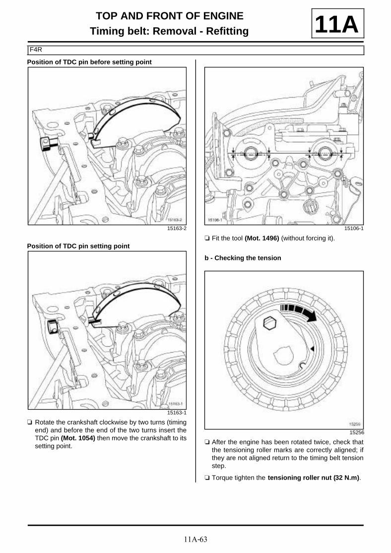
11A-63
TOP AND FRONT OF ENGINETiming belt: Removal - Refitting
F4R
11APosition of TDC pin before setting point
Position of TDC pin setting point
a Rotate the crankshaft clockwise by two turns (timingend) and before the end of the two turns insert theTDC pin (Mot. 1054) then move the crankshaft to itssetting point.
a Fit the tool (Mot. 1496) (without forcing it).
b - Checking the tension
a After the engine has been rotated twice, check thatthe tensioning roller marks are correctly aligned; ifthey are not aligned return to the timing belt tensionstep.
a Torque tighten the tensioning roller nut (32 N.m).
15163-2
15163-1
15106-1
15256

11A-64
TOP AND FRONT OF ENGINETiming belt: Removal - Refitting
F4R
11A
a Position the (Mot. 1801).
a Bring the toothed sprockets of the (Mot. 1801) intocontact with the camshaft pulleys.
a Torque tighten the toothed sprocket nuts (80N.m).
a Undo:
- the old inlet camshaft dephaser bolt,
- the old exhaust camshaft nut.
a Fit without tightening:
- a new bolt on the camshaft dephaser,
- a new nut on the exhaust camshaft pulley.
a Tighten to torque:
- the new bolt on the camshaft dephaser (100N.m),
- the new nut on the exhaust camshaft pulley (30N.m).
a Remove:
- the bolt (33) from the (Mot. 1496),
- the camshaft setting tool (Mot. 1496).
a Angle tighten the exhaust camshaft pulley nut (86˚±±±± 6˚).
a Remove:
- the (Mot. 1801),
- the TDC setting pin (Mot. 1054).
a Refit:
- a new cap on the end of the inlet camshaft usingthe tool (Mot. 1487),
- a new cap on the end of the exhaust camshaftusing the tool (Mot. 1488),
- a new blanking cover on the camshaft dephaser.
a Torque tighten the camshaft dephaser blankingcover (25 N.m).
III - FINAL OPERATION
a Refit:
- the lower timing cover,
- the lower timing cover heat shield,
- the upper timing cover,
- the bulkhead upper heat shield,
- the right-hand suspended engine mounting (see19D, Engine mounting, Right-hand suspendedengine mounting: Removal - Refitting, page19D-18) .
a Remove the tool (Mot. 1453) fitted with the tool(Mot. 1453-01) and the safety strap(s).
a Connect the turbocharger vacuum pipe.
a Clip on the turbocharger vacuum pipe clip.
135741
21880

11A-65
TOP AND FRONT OF ENGINETiming belt: Removal - Refitting
F4R
11Aa Refit the gearbox side lifting eye.
a Fit the engine wiring.
a Refit the engine wiring nut on the gearbox side liftingeye.
a Connect the turbocharger air outlet pipe.
a Torque tighten the clip of the turbocharger airoutlet pipe (6 N.m).
a Refit:
- the retaining bracket bolts on the turbocharger airoutlet pipe,
- the air pipe retaining bolt on the intake distributor.
a Clip on the petrol vapour rebreathing pipes.
a Remove:
- the right-hand suspended engine mounting cover,
- the blanking plugs.
a Connect:
- the petrol vapour rebreathing pipe,
- the fuel supply pipe to the injector rail,
- the pipe on the petrol vapour rebreathing solenoidvalve.
a Refit:
- the scoop under the scuttle panel grille (see Scoopunder scuttle panel grille: Removal - Refitting)(56A, Exterior equipment),
- the scuttle panel grille (see Scuttle panel grille:Removal - Refitting) (56A, Exterior equipment),
- the windscreen wiper arms (see Windscreen wi-per arm: Removal - Refitting) (85A, Wiping -Washing).
a Position the exhaust connecting hose.
a Refit:
- a new connecting hose seal,
- the rubber mounting bush retaining bolt on the ex-haust hose,
- the exhaust connecting hose nuts.
a Fit the electric coolant pump.
a Refit:
- the lower engine tie-bar (see 19D, Engine moun-ting, Lower engine tie-bar: Removal - Refitting,page 19D-33) ,
- the crankshaft accessories pulley (see 11A, Topand front of engine, Crankshaft accessoriespulley: Removal - Refitting, page 11A-15) ,
- the accessories belt (see 11A, Top and front ofengine, Accessories belt: Removal - Refitting,page 11A-7) ,
- the radiator mounting cross member (see Radiatorsupport cross member: Removal - Refitting)(31A, Front axle components),
- the front bumper (see Front bumper: Removal -Refitting) (55A, Exterior protection),
- the front section of the front wheel arch liners (seeFront wheel arch liner: Removal - Refitting)(55A, Exterior protection),
- the front wheels (see Wheel: Removal - Refitting)(35A, Wheels and tyres),
- the engine undertray,
- the battery tray (see Battery tray: Removal - Re-fitting) (80A, Battery),
- the battery (see Battery: Removal - Refitting)(80A, Battery),
- the engine cover.

11A-66
TOP AND FRONT OF ENGINETiming belt: Removal - Refitting
K4M
11AREMOVAL
I - REMOVAL PREPARATION OPERATION
a Position the vehicle on a two-post lift (see Vehicle:Towing and lifting) (02A, Lifting equipment).
a Disconnect the battery (see Battery: Removal - Re-fitting) (80A, Battery).
a Remove:
- the engine cover,
- the throttle valve (see 12A, Fuel mixture, Throttlevalve: Removal - Refitting, page 12A-17) .
a Unclip the engine wiring connector (1) from the liftingeye.
a Remove:
- the dipstick guide tube bolt,
- the engine wiring retaining nut (2) .
a Unclip the engine wiring connector from the liftingeye.
a Remove the retaining nut from the engine wiring.
Essential special tooling
Mot. 1489 TDC locating pin.
Mot. 799-01 Timing gear wheel immobili-ser.
Mot. 1496 Tool for setting camshaft.
Mot. 1750 Addition to retaining cams-haft setting tool Mot. 1496 .
Mot. 1490-01 Locking and adjusting cams-haft pulleys.
Mot. 1487 Tool for removing the cams-haft covers (57 mm diame-ter).
Mot. 1488 Tool for removing the cams-haft covers (43 mm diame-ter).
Tightening torquesm
fixed roller bolt 50 N.m
tensioning roller nut (ini-tial torque)
7 N.m
lower timing cover bolts 12 N.m
new crankshaft acces-sories pulley bolt
40 N.m + 145˚±±±± 15˚
timing tensioning rollernut
27 N.m
inlet camshaft pulley nut 30 N.m + 84˚ ±±±±4
camshaft dephaser bolt 100 N.m
exhaust camshaft pul-ley nut
30 N.m + 84˚ ±±±±4
lifting eye bolts 10 N.m
dipstick guide tube bolt 10 N.m
TDC setting pin plug 25 N.m
upper timing cover bolts 46 N.m
upper timing cover nuts 46 N.m
K4M, and 848
136454
K4M, and 858 or 866
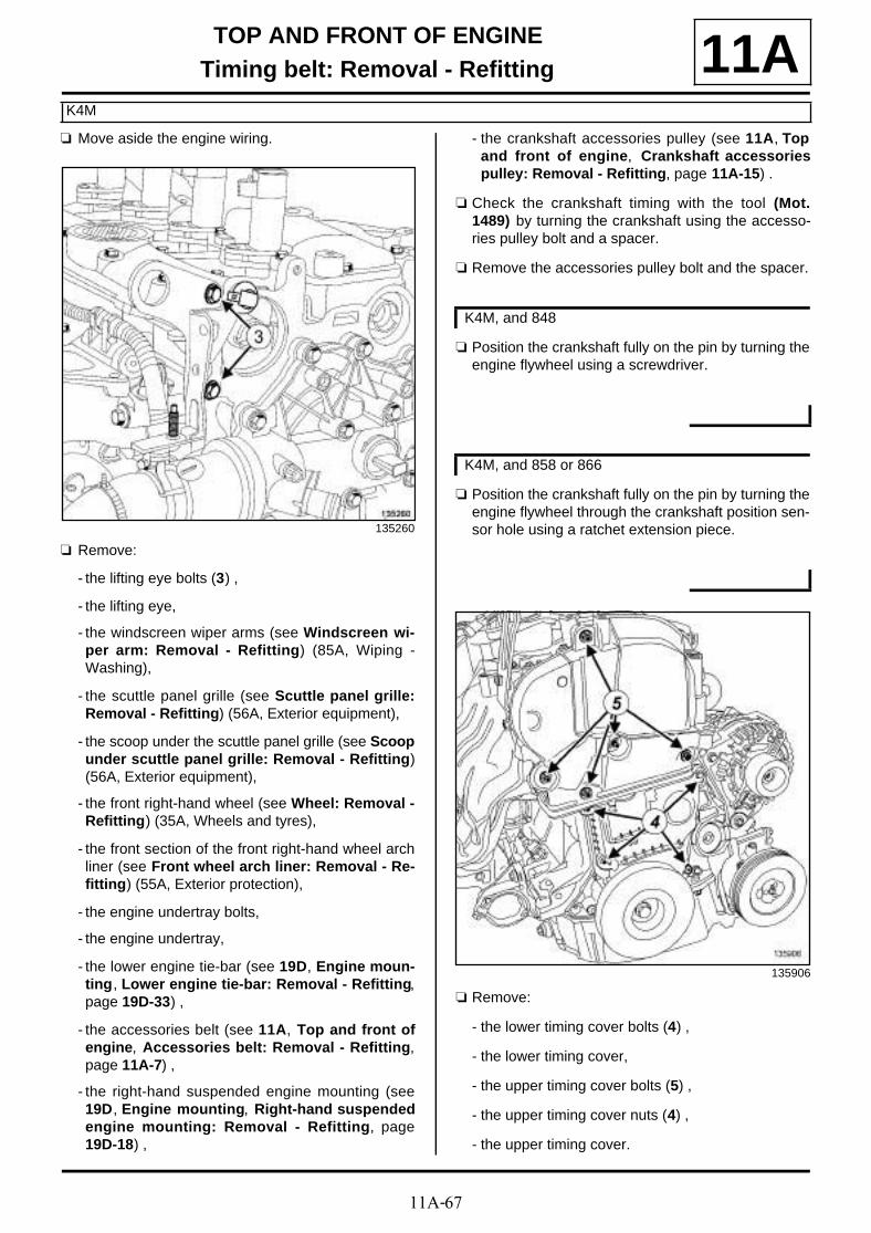
11A-67
TOP AND FRONT OF ENGINETiming belt: Removal - Refitting
K4M
11Aa Move aside the engine wiring.
a Remove:
- the lifting eye bolts (3) ,
- the lifting eye,
- the windscreen wiper arms (see Windscreen wi-per arm: Removal - Refitting) (85A, Wiping -Washing),
- the scuttle panel grille (see Scuttle panel grille:Removal - Refitting) (56A, Exterior equipment),
- the scoop under the scuttle panel grille (see Scoopunder scuttle panel grille: Removal - Refitting)(56A, Exterior equipment),
- the front right-hand wheel (see Wheel: Removal -Refitting) (35A, Wheels and tyres),
- the front section of the front right-hand wheel archliner (see Front wheel arch liner: Removal - Re-fitting) (55A, Exterior protection),
- the engine undertray bolts,
- the engine undertray,
- the lower engine tie-bar (see 19D, Engine moun-ting, Lower engine tie-bar: Removal - Refitting,page 19D-33) ,
- the accessories belt (see 11A, Top and front ofengine, Accessories belt: Removal - Refitting,page 11A-7) ,
- the right-hand suspended engine mounting (see19D, Engine mounting, Right-hand suspendedengine mounting: Removal - Refitting, page19D-18) ,
- the crankshaft accessories pulley (see 11A, Topand front of engine, Crankshaft accessoriespulley: Removal - Refitting, page 11A-15) .
a Check the crankshaft timing with the tool (Mot.1489) by turning the crankshaft using the accesso-ries pulley bolt and a spacer.
a Remove the accessories pulley bolt and the spacer.
a Position the crankshaft fully on the pin by turning theengine flywheel using a screwdriver.
a Position the crankshaft fully on the pin by turning theengine flywheel through the crankshaft position sen-sor hole using a ratchet extension piece.
a Remove:
- the lower timing cover bolts (4) ,
- the lower timing cover,
- the upper timing cover bolts (5) ,
- the upper timing cover nuts (4) ,
- the upper timing cover.
135260
K4M, and 848
K4M, and 858 or 866
135906
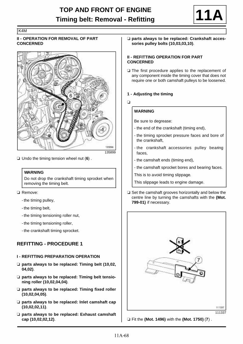
11A-68
TOP AND FRONT OF ENGINETiming belt: Removal - Refitting
K4M
11AII - OPERATION FOR REMOVAL OF PART CONCERNED
a Undo the timing tension wheel nut (6) .
a Remove:
- the timing pulley,
- the timing belt,
- the timing tensioning roller nut,
- the timing tensioning roller,
- the crankshaft timing sprocket.
REFITTING - PROCEDURE 1
I - REFITTING PREPARATION OPERATION
a parts always to be replaced: Timing belt (10,02,04,02).
a parts always to be replaced: Timing belt tensio-ning roller (10,02,04,04).
a parts always to be replaced: Timing fixed roller(10,02,04,05).
a parts always to be replaced: Inlet camshaft cap(10,02,02,11).
a parts always to be replaced: Exhaust camshaftcap (10,02,02,12).
a parts always to be replaced: Crankshaft acces-sories pulley bolts (10,03,03,10).
II - REFITTING OPERATION FOR PART CONCERNED
a The first procedure applies to the replacement ofany component inside the timing cover that does notrequire one or both camshaft pulleys to be loosened.
1 - Adjusting the timing
a
a Set the camshaft grooves horizontally and below thecentre line by turning the camshafts with the (Mot.799-01) if necessary.
a Fit the (Mot. 1496) with the (Mot. 1750) (7) .
135899
WARNING
Do not drop the crankshaft timing sprocket whenremoving the timing belt.
WARNING
Be sure to degrease:
- the end of the crankshaft (timing end),
- the timing sprocket pressure faces and bore ofthe crankshaft,
- the crankshaft accessories pulley bearingfaces,
- the camshaft ends (timing end),
- the camshaft sprocket bores and bearing faces.
This is to avoid timing slippage.
This slippage leads to engine damage.
111337

11A-69
TOP AND FRONT OF ENGINETiming belt: Removal - Refitting
K4M
11A
a Fit:
- the (Mot. 1496) (8) fitted with the (Mot. 1750) onthe end of the camshaft,
- a lifting eye bolt (9) to secure the tool (Mot. 1496).
a Check that the camshaft pulley mark (10) (Renaultsign) is vertical and pointing upwards.
a Use a pencil to make marks between the camshaftpulleys and the rocker cover.
135240
K4M, and 848
135899

11A-70
TOP AND FRONT OF ENGINETiming belt: Removal - Refitting
K4M
11A
a Check that the exhaust camshaft pulley mark (11)(Renault sign) and the camshaft dephaser line arevertical and pointing upwards.
a Use a pencil to make marks between the exhaustcamshaft pulley, the camshaft dephaser and the roc-ker cover.
2 - Refitting
a Fit a new tensioning roller by positioning the tensio-ning roller lug in the groove (12) .
a Screw on the tensioning roller nut without tighteningit.
a Refit:
- the timing sprocket (13) .
- a new timing belt,
- a new fixed roller (14) .
K4M, and 858 or 866
136522
108879
135899

11A-71
TOP AND FRONT OF ENGINETiming belt: Removal - Refitting
K4M
11A
a Torque tighten the fixed roller bolt (50 N.m) (15) .
3 - Timing belt tension
a Position the adjustable index (16) opposite the mark(17) , by turning the eccentric (18) clockwise using a6 mm Allen key.
a Torque tighten the tensioning roller nut (initial tor-que) (7 N.m).
a Refit the lower timing cover.
a Tighten to torque the lower timing cover bolts (12N.m).
a Refit the crankshaft accessories pulley.
a Use a screwdriver (19) to check that the flywheeldoes not turn (clockwise at the timing end), otherwi-se bring the crankshaft back into contact with theTDC setting pin (Mot. 1489) (20) using the screwdri-ver; the crankshaft groove should be at the top.
135899
103263
K4M, and 848
135257
14489
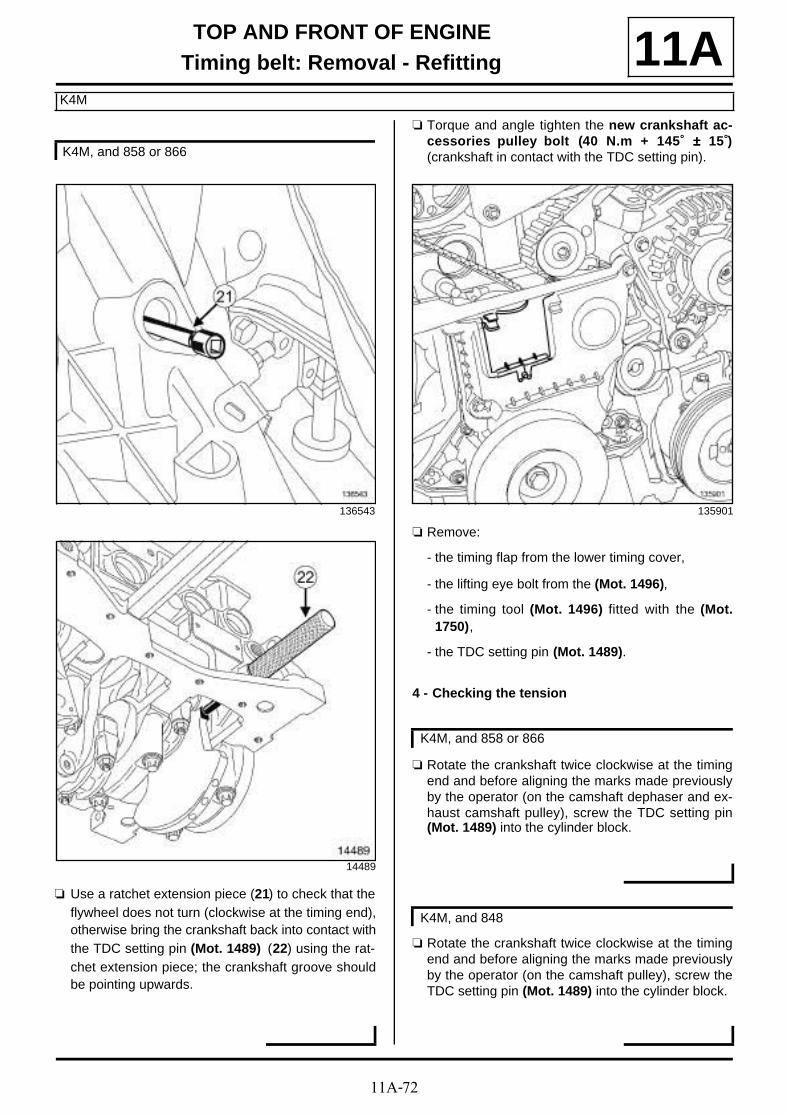
11A-72
TOP AND FRONT OF ENGINETiming belt: Removal - Refitting
K4M
11A
a Use a ratchet extension piece (21) to check that theflywheel does not turn (clockwise at the timing end),otherwise bring the crankshaft back into contact withthe TDC setting pin (Mot. 1489) (22) using the rat-chet extension piece; the crankshaft groove shouldbe pointing upwards.
a Torque and angle tighten the new crankshaft ac-cessories pulley bolt (40 N.m + 145˚ ±±±± 15 )̊(crankshaft in contact with the TDC setting pin).
a Remove:
- the timing flap from the lower timing cover,
- the lifting eye bolt from the (Mot. 1496),
- the timing tool (Mot. 1496) fitted with the (Mot.1750),
- the TDC setting pin (Mot. 1489).
4 - Checking the tension
a Rotate the crankshaft twice clockwise at the timingend and before aligning the marks made previouslyby the operator (on the camshaft dephaser and ex-haust camshaft pulley), screw the TDC setting pin(Mot. 1489) into the cylinder block.
a Rotate the crankshaft twice clockwise at the timingend and before aligning the marks made previouslyby the operator (on the camshaft pulley), screw theTDC setting pin (Mot. 1489) into the cylinder block.
K4M, and 858 or 866
136543
14489
135901
K4M, and 858 or 866
K4M, and 848
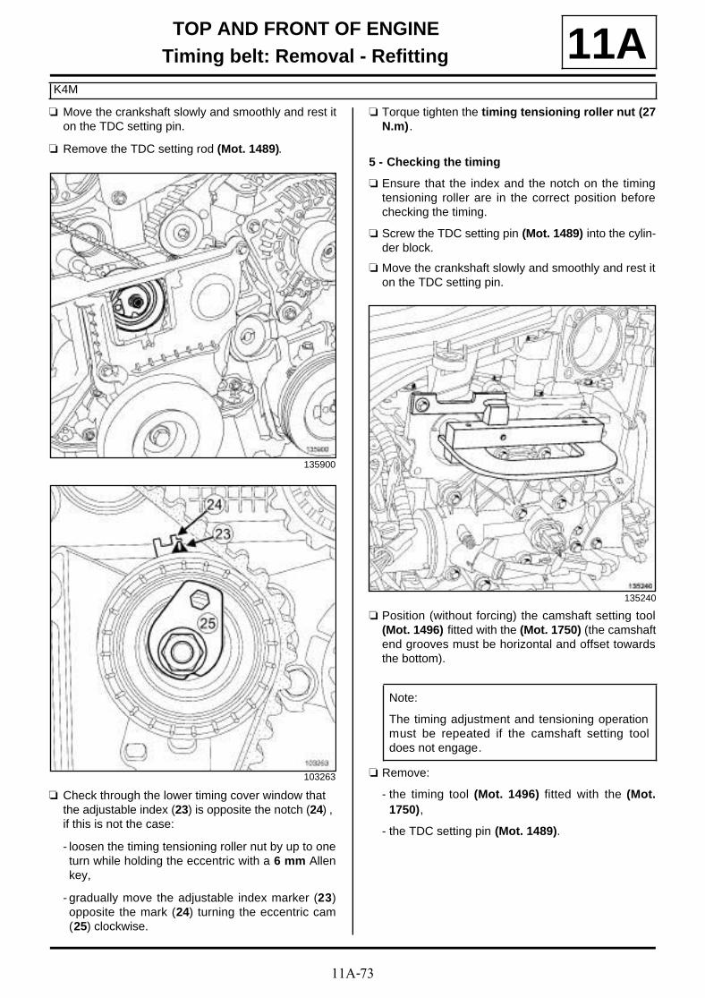
11A-73
TOP AND FRONT OF ENGINETiming belt: Removal - Refitting
K4M
11Aa Move the crankshaft slowly and smoothly and rest it
on the TDC setting pin.
a Remove the TDC setting rod (Mot. 1489).
a Check through the lower timing cover window that the adjustable index (23) is opposite the notch (24) , if this is not the case:
- loosen the timing tensioning roller nut by up to oneturn while holding the eccentric with a 6 mm Allenkey,
- gradually move the adjustable index marker (23)opposite the mark (24) turning the eccentric cam(25) clockwise.
a Torque tighten the timing tensioning roller nut (27N.m).
5 - Checking the timing
a Ensure that the index and the notch on the timingtensioning roller are in the correct position beforechecking the timing.
a Screw the TDC setting pin (Mot. 1489) into the cylin-der block.
a Move the crankshaft slowly and smoothly and rest iton the TDC setting pin.
a Position (without forcing) the camshaft setting tool(Mot. 1496) fitted with the (Mot. 1750) (the camshaftend grooves must be horizontal and offset towardsthe bottom).
a Remove:
- the timing tool (Mot. 1496) fitted with the (Mot.1750),
- the TDC setting pin (Mot. 1489).
135900
103263
135240
Note:
The timing adjustment and tensioning operationmust be repeated if the camshaft setting tooldoes not engage.

11A-74
TOP AND FRONT OF ENGINETiming belt: Removal - Refitting
K4M
11A
a Refit the lower timing cover flap, checking that thelocating pin (26) fits properly in the notch (27) .
REFITTING -PROCEDURE 2
I - REFITTING PREPARATION OPERATION
a parts always to be replaced: Timing belt (10,02,04,02).
a parts always to be replaced: Timing belt tensio-ning roller (10,02,04,04).
a parts always to be replaced: Timing fixed roller(10,02,04,05).
a parts always to be replaced: Inlet camshaft cap(10,02,02,11).
a parts always to be replaced: Exhaust camshaftcap (10,02,02,12).
a parts always to be replaced: Crankshaft acces-sories pulley bolts (10,03,03,10).
II - REFITTING OPERATION FOR PART CONCERNED
a The second procedure is used for the replacementof all components requiring the loosening of one ormore of the camshaft pulleys.
1 - Adjusting the timing
a
a When replacing the camshaft dephaser (see 11A,Top and front of engine, Camshaft dephaser: Re-moval - Refitting, page 11A-177) .
135902
Note:
If the stud loosens with the nut (see 11A, Topand front of engine, Camshaft: Removal -Refitting, page 11A-114) (Technical Note3887A,11A, Top and front of engine).
WARNING
Always degrease:
- the end of the crankshaft (timing end),
- the timing sprocket pressure faces and bore ofthe crankshaft,
- the crankshaft accessories pulley bearingfaces,
- the camshaft ends (timing end),
- the camshaft sprocket bores and bearing faces.
This is to avoid timing slippage.
This slippage leads to engine damage.

11A-75
TOP AND FRONT OF ENGINETiming belt: Removal - Refitting
K4M
11A
a Position the camshaft grooves horizontally and be-low the centre line, by turning the camshafts with the(Mot. 1496) if necessary.
a Fit the (Mot. 1496) with the (Mot. 1750) (28) .
a Fit:
- the (Mot. 1496) (30) fitted with the (Mot. 1750) onthe end of the camshaft,
- a lifting eye bolt (29) to secure the tool (Mot. 1496).
a Refit the crankshaft sprocket.
135905
103261
111337
135240
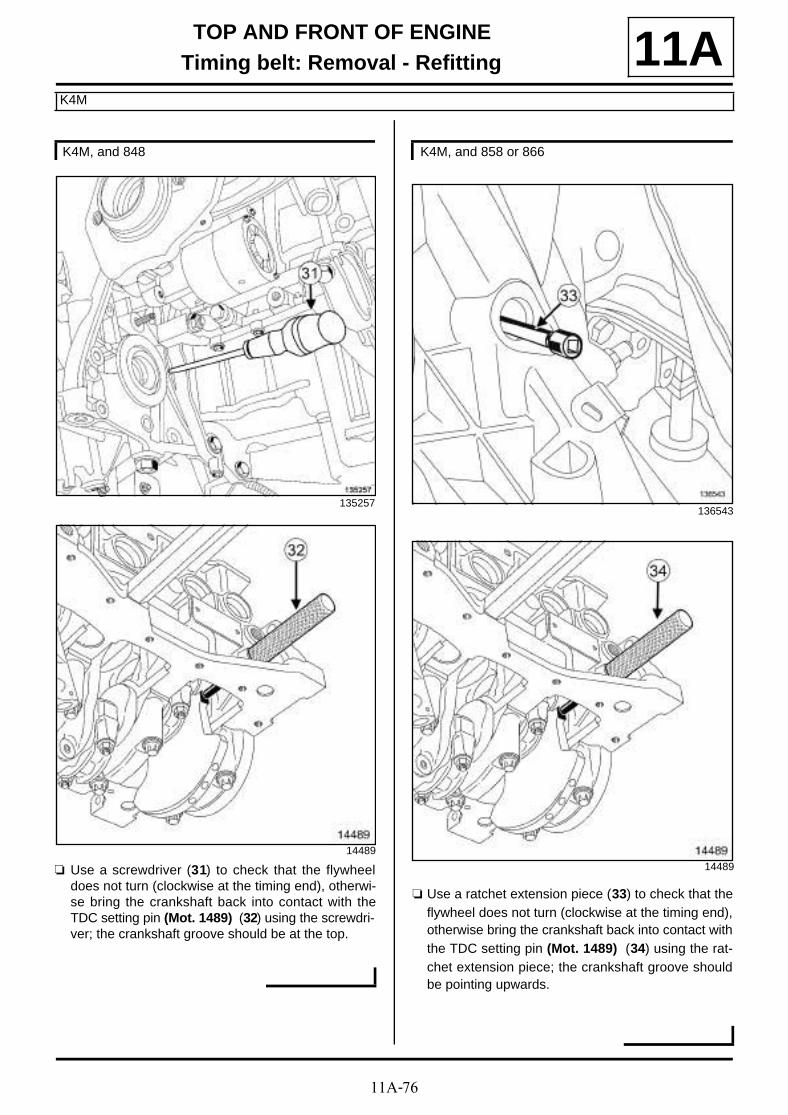
11A-76
TOP AND FRONT OF ENGINETiming belt: Removal - Refitting
K4M
11A
a Use a screwdriver (31) to check that the flywheeldoes not turn (clockwise at the timing end), otherwi-se bring the crankshaft back into contact with theTDC setting pin (Mot. 1489) (32) using the screwdri-ver; the crankshaft groove should be at the top.
a Use a ratchet extension piece (33) to check that theflywheel does not turn (clockwise at the timing end),otherwise bring the crankshaft back into contact withthe TDC setting pin (Mot. 1489) (34) using the rat-chet extension piece; the crankshaft groove shouldbe pointing upwards.
K4M, and 848
135257
14489
K4M, and 858 or 866
136543
14489
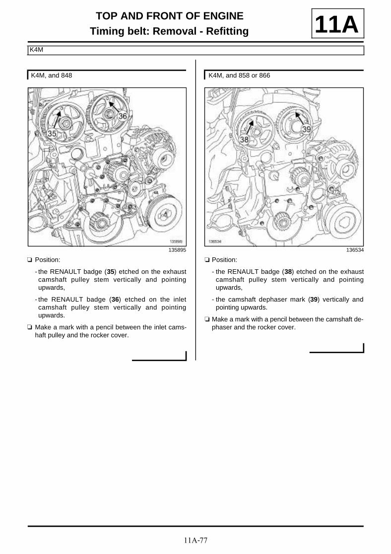
11A-77
TOP AND FRONT OF ENGINETiming belt: Removal - Refitting
K4M
11A
a Position:
- the RENAULT badge (35) etched on the exhaustcamshaft pulley stem vertically and pointingupwards,
- the RENAULT badge (36) etched on the inletcamshaft pulley stem vertically and pointingupwards.
a Make a mark with a pencil between the inlet cams-haft pulley and the rocker cover.
a Position:
- the RENAULT badge (38) etched on the exhaustcamshaft pulley stem vertically and pointingupwards,
- the camshaft dephaser mark (39) vertically andpointing upwards.
a Make a mark with a pencil between the camshaft de-phaser and the rocker cover.
K4M, and 848
135895
K4M, and 858 or 866
136534

11A-78
TOP AND FRONT OF ENGINETiming belt: Removal - Refitting
K4M
11A
a Fit a new tensioning roller by positioning the tensio-ning roller lug in the groove (40) .
a Screw on the tensioning roller nut without tighteningit.
a Refit a new timing belt on the pulley of each cams-haft (without moving each of the camshaft pulleys).
a Fit the (Mot. 1490-01) (41) on the camshaft pulleys(use the bolt and nut of the upper timing cover to fitthe (Mot. 1490-01)).
108879
K4M, and 848
135896
Note:
Take care to tighten the timing belt between thetwo camshaft pulleys correctly.
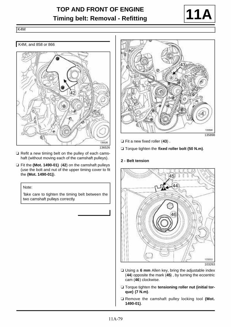
11A-79
TOP AND FRONT OF ENGINETiming belt: Removal - Refitting
K4M
11A
a Refit a new timing belt on the pulley of each cams-haft (without moving each of the camshaft pulleys).
a Fit the (Mot. 1490-01) (42) on the camshaft pulleys(use the bolt and nut of the upper timing cover to fitthe (Mot. 1490-01)).
a Fit a new fixed roller (43) .
a Torque tighten the fixed roller bolt (50 N.m).
2 - Belt tension
a Using a 6 mm Allen key, bring the adjustable index(44) opposite the mark (45) , by turning the eccentriccam (46) clockwise.
a Torque tighten the tensioning roller nut (initial tor-que) (7 N.m).
a Remove the camshaft pulley locking tool (Mot.1490-01).
K4M, and 858 or 866
136526
Note:
Take care to tighten the timing belt between thetwo camshaft pulleys correctly.
135898
103263

11A-80
TOP AND FRONT OF ENGINETiming belt: Removal - Refitting
K4M
11A
a
a
a Rotate the timing system through six revolutionswith the exhaust camshaft pulley, using the (Mot.799-01).
a Check that the adjustable index (47) is opposite the notch (48) , if this is not the case:
- loosen the timing tensioning roller nut by up to oneturn while holding the eccentric with a 6 mm Allenkey,
- gradually move the adjustable index marker (47)opposite the mark (48) turning the eccentric cam(49) clockwise.
a Torque tighten the tensioning roller nut (27 N.m).
K4M, and 848
Note:
Check that the exhaust camshaft pulley nut andthe inlet camshaft pulley nut do not come intocontact with their respective pulleys. Also, fromtime to time, secure the pulley of each camshaftagainst its respective camshaft.
K4M, and 858 or 866
Note:
Check that the exhaust camshaft pulley nut andthe camshaft dephaser pulley bolt do not comeinto contact with their respective pulleys. Also,from time to time, secure the pulley of eachcamshaft against its respective camshaft.
103263

11A-81
TOP AND FRONT OF ENGINETiming belt: Removal - Refitting
K4M
11A
a Check that:
- the RENAULT badge (50) etched on the exhaustcamshaft pulley stem is positioned vertically andpointing upwards,
- the RENAULT badge (51) etched on the inletcamshaft pulley stem is positioned vertically andpointing upwards.
a Check that:
- the RENAULT badge (52) etched on the exhaustcamshaft pulley stem is positioned vertically andpointing upwards,
- the camshaft dephaser mark (53) vertically andpointing upwards.
K4M, and 848
135899
K4M, and 858 or 866
136522
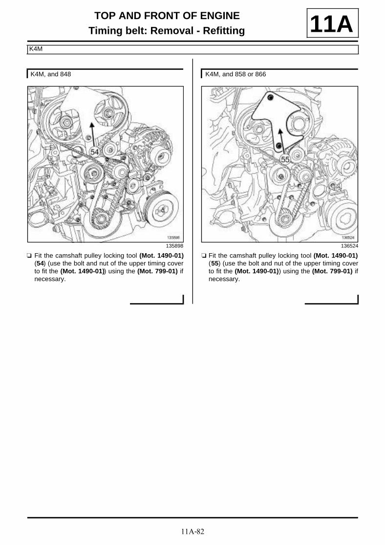
11A-82
TOP AND FRONT OF ENGINETiming belt: Removal - Refitting
K4M
11A
a Fit the camshaft pulley locking tool (Mot. 1490-01)(54) (use the bolt and nut of the upper timing coverto fit the (Mot. 1490-01)) using the (Mot. 799-01) ifnecessary.
a Fit the camshaft pulley locking tool (Mot. 1490-01)(55) (use the bolt and nut of the upper timing coverto fit the (Mot. 1490-01)) using the (Mot. 799-01) ifnecessary.
K4M, and 848
135898
K4M, and 858 or 866
136524

11A-83
TOP AND FRONT OF ENGINETiming belt: Removal - Refitting
K4M
11A
a Use a screwdriver (56) to check that the flywheeldoes not turn (clockwise at the timing end), otherwi-se bring the crankshaft back into contact with theTDC setting pin (Mot. 1489) (57) using the screwdri-ver; the crankshaft groove should be at the top.
a Use a ratchet extension piece (58) to check that theflywheel does not turn (clockwise at the timing end),otherwise bring the crankshaft back into contact withthe TDC setting pin (Mot. 1489) (59) using the rat-chet extension piece; the crankshaft groove shouldbe pointing upwards.
K4M, and 848
135257
14489
K4M, and 858 or 866
136543
14489

11A-84
TOP AND FRONT OF ENGINETiming belt: Removal - Refitting
K4M
11A
a Refit the lower timing cover (60) .
a Tighten to torque the lower timing cover bolts (12N.m).
a Refit the accessories crankshaft pulley with a newbolt.
a Tighten to torque and angle the new crankshaft ac-cessories pulley bolt (40 N.m + 145˚ ±±±± 15˚)(crankshaft in contact with the TDC setting pin).
a Tighten to torque the inlet camshaft pulley nut (30N.m + 84˚ ±±±± 4) (61) .
135892
K4M, and 848
135235

11A-85
TOP AND FRONT OF ENGINETiming belt: Removal - Refitting
K4M
11A
a Torque tighten the camshaft dephaser bolt (100N.m).
a Refit the camshaft dephaser blanking cover (62) .
a Tighten to torque the exhaust camshaft pulley nut(30 N.m + 84˚ ±±±± 4).
a Remove:
- the timing flap from the lower timing cover,
- the lifting eye bolt from the (Mot. 1496),
- the timing tool (Mot. 1496) fitted with the (Mot.1750),
- the camshaft pulley locking tool (Mot. 1490-01),
- the TDC setting pin (Mot. 1489).
3 - Checking the tension
a Rotate the crankshaft twice clockwise at the timingend and before aligning the RENAULT marks on thecamshaft pulleys, made previously by the operator,screw the TDC setting pin (Mot. 1489) into the cylin-der block.
a Move the crankshaft slowly and smoothly and rest iton the TDC setting pin.
a Remove the TDC setting rod (Mot. 1489).
K4M, and 858 or 866
136530
135902
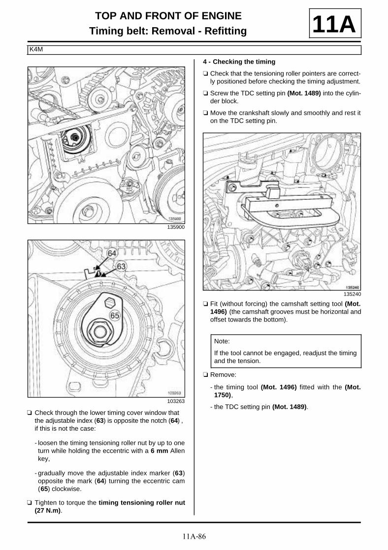
11A-86
TOP AND FRONT OF ENGINETiming belt: Removal - Refitting
K4M
11A
a Check through the lower timing cover window that the adjustable index (63) is opposite the notch (64) , if this is not the case:
- loosen the timing tensioning roller nut by up to oneturn while holding the eccentric with a 6 mm Allenkey,
- gradually move the adjustable index marker (63)opposite the mark (64) turning the eccentric cam(65) clockwise.
a Tighten to torque the timing tensioning roller nut(27 N.m).
4 - Checking the timing
a Check that the tensioning roller pointers are correct-ly positioned before checking the timing adjustment.
a Screw the TDC setting pin (Mot. 1489) into the cylin-der block.
a Move the crankshaft slowly and smoothly and rest iton the TDC setting pin.
a Fit (without forcing) the camshaft setting tool (Mot.1496) (the camshaft grooves must be horizontal andoffset towards the bottom).
a Remove:
- the timing tool (Mot. 1496) fitted with the (Mot.1750),
- the TDC setting pin (Mot. 1489).
135900
103263
135240
Note:
If the tool cannot be engaged, readjust the timingand the tension.
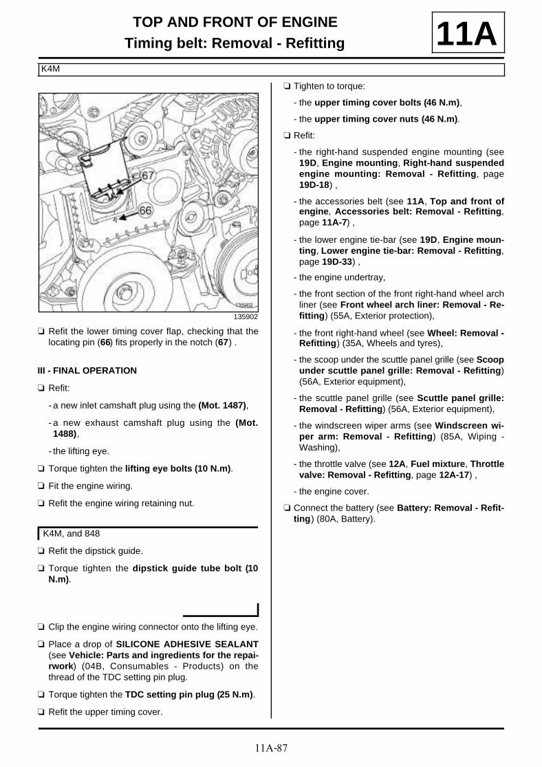
11A-87
TOP AND FRONT OF ENGINETiming belt: Removal - Refitting
K4M
11A
a Refit the lower timing cover flap, checking that thelocating pin (66) fits properly in the notch (67) .
III - FINAL OPERATION
a Refit:
- a new inlet camshaft plug using the (Mot. 1487),
- a new exhaust camshaft plug using the (Mot.1488),
- the lifting eye.
a Torque tighten the lifting eye bolts (10 N.m).
a Fit the engine wiring.
a Refit the engine wiring retaining nut.
a Refit the dipstick guide.
a Torque tighten the dipstick guide tube bolt (10N.m).
a Clip the engine wiring connector onto the lifting eye.
a Place a drop of SILICONE ADHESIVE SEALANT(see Vehicle: Parts and ingredients for the repai-rwork) (04B, Consumables - Products) on thethread of the TDC setting pin plug.
a Torque tighten the TDC setting pin plug (25 N.m).
a Refit the upper timing cover.
a Tighten to torque:
- the upper timing cover bolts (46 N.m),
- the upper timing cover nuts (46 N.m).
a Refit:
- the right-hand suspended engine mounting (see19D, Engine mounting, Right-hand suspendedengine mounting: Removal - Refitting, page19D-18) ,
- the accessories belt (see 11A, Top and front ofengine, Accessories belt: Removal - Refitting,page 11A-7) ,
- the lower engine tie-bar (see 19D, Engine moun-ting, Lower engine tie-bar: Removal - Refitting,page 19D-33) ,
- the engine undertray,
- the front section of the front right-hand wheel archliner (see Front wheel arch liner: Removal - Re-fitting) (55A, Exterior protection),
- the front right-hand wheel (see Wheel: Removal -Refitting) (35A, Wheels and tyres),
- the scoop under the scuttle panel grille (see Scoopunder scuttle panel grille: Removal - Refitting)(56A, Exterior equipment),
- the scuttle panel grille (see Scuttle panel grille:Removal - Refitting) (56A, Exterior equipment),
- the windscreen wiper arms (see Windscreen wi-per arm: Removal - Refitting) (85A, Wiping -Washing),
- the throttle valve (see 12A, Fuel mixture, Throttlevalve: Removal - Refitting, page 12A-17) ,
- the engine cover.
a Connect the battery (see Battery: Removal - Refit-ting) (80A, Battery).
135902
K4M, and 848

11A-88
TOP AND FRONT OF ENGINERocker cover: Removal - Refitting
K9K
11A
REMOVAL
I - REMOVAL PREPARATION OPERATION
a Remove:
- the engine cover,
- the engine undertray bolts,
- the engine undertray.
- the windscreen wiper arms (see Windscreen wi-per arm: Removal - Refitting) (85A, Wiping -Washing),
- the scuttle panel grille (see Scuttle panel grille:Removal - Refitting) (56A, Exterior equipment),
- the scoop under the scuttle panel grille (see Scoopunder scuttle panel grille: Removal - Refitting)(56A, Exterior equipment),
- the right-hand suspended engine mounting (see19D, Engine mounting, Right-hand suspendedengine mounting: Removal - Refitting, page19D-18) .
a Remove the camshaft position sensor (see 13B,Diesel injection, Camshaft position sensor: Re-moval - Refitting, page 13B-19) .
a Remove the upper timing cover (1) by pressing theclips (2) .
Tightening torquesm
rocker cover bolts 11 N.m
lower engine tie-bar bolton the subframe
180 N.m
lower engine tie-bar bolton the lower engine tie-bar support
180 N.m
IMPORTANTWear leaktight gloves (Nitrile type) for this opera-tion.
K9K, and 830
K9K, and 832
135494
135495
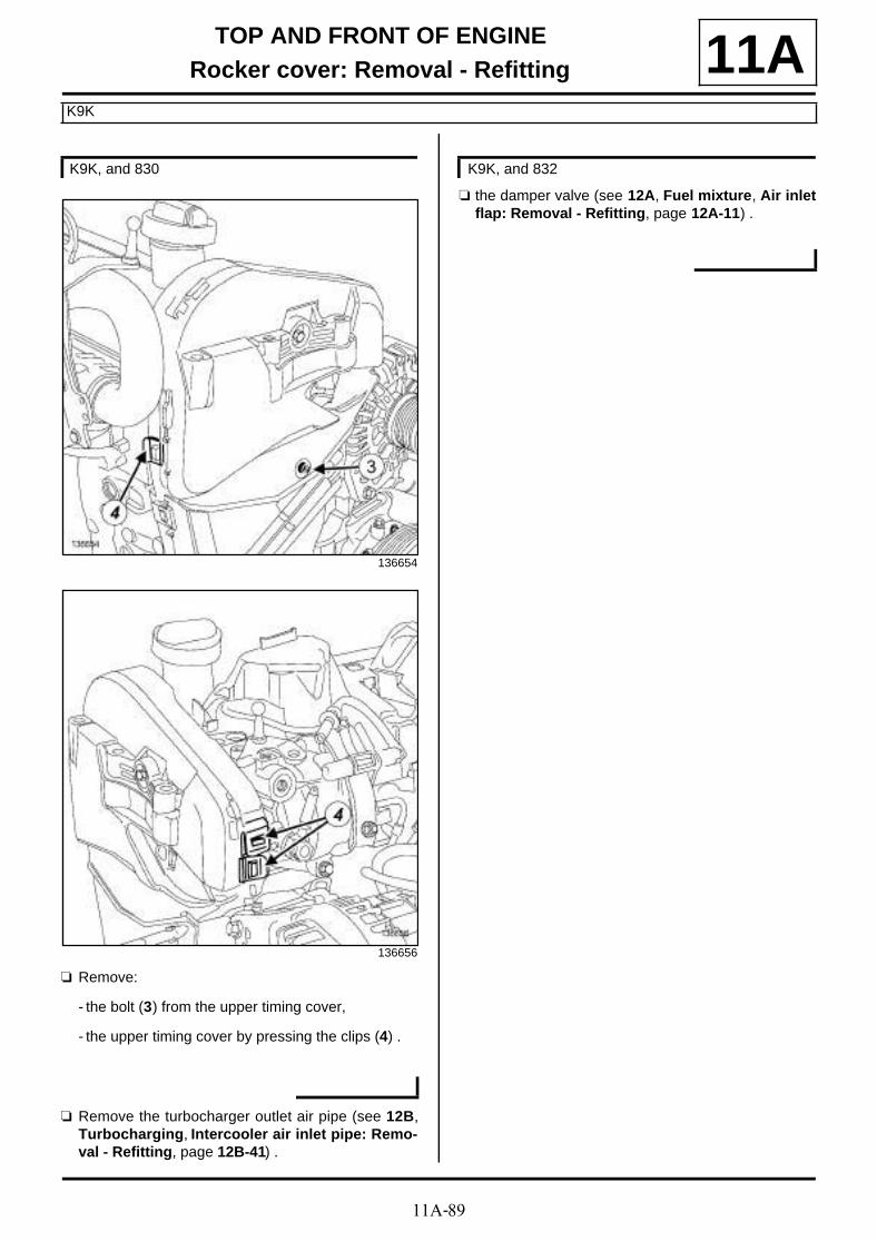
11A-89
TOP AND FRONT OF ENGINERocker cover: Removal - Refitting
K9K
11A
a Remove:
- the bolt (3) from the upper timing cover,
- the upper timing cover by pressing the clips (4) .
a Remove the turbocharger outlet air pipe (see 12B,Turbocharging, Intercooler air inlet pipe: Remo-val - Refitting, page 12B-41) .
a the damper valve (see 12A, Fuel mixture, Air inletflap: Removal - Refitting, page 12A-11) .
K9K, and 830
136654
136656
K9K, and 832

11A-90
TOP AND FRONT OF ENGINERocker cover: Removal - Refitting
K9K
11A
a Disconnect the oil vapour rebreathing pipe from theair filter unit air outlet pipe at (5) .
a Separate the clip (6) of the oil vapour rebreathingpipe on the oil vapour rebreathing valve.
a Disconnect the oil vapour rebreathing pipe from theoil vapour rebreathing valve.
a Remove the nut (7) of the gearbox breather pipemounting.
a Move aside the gearbox breather pipe mounting.
a Remove:
- the bolts (8) of the oil vapour rebreathing valve
K9K, and 830
135880
135879
135845
112325
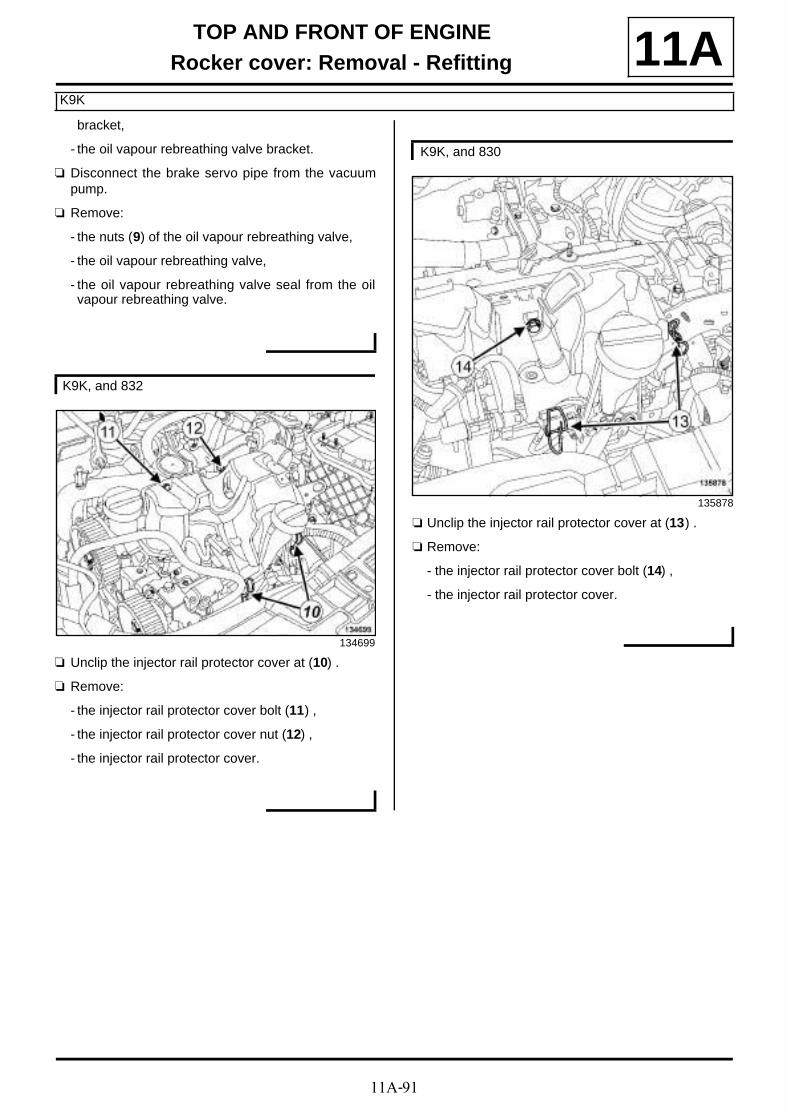
11A-91
TOP AND FRONT OF ENGINERocker cover: Removal - Refitting
K9K
11Abracket,
- the oil vapour rebreathing valve bracket.
a Disconnect the brake servo pipe from the vacuumpump.
a Remove:
- the nuts (9) of the oil vapour rebreathing valve,
- the oil vapour rebreathing valve,
- the oil vapour rebreathing valve seal from the oilvapour rebreathing valve.
a Unclip the injector rail protector cover at (10) .
a Remove:
- the injector rail protector cover bolt (11) ,
- the injector rail protector cover nut (12) ,
- the injector rail protector cover.
a Unclip the injector rail protector cover at (13) .
a Remove:
- the injector rail protector cover bolt (14) ,
- the injector rail protector cover.
K9K, and 832
134699
K9K, and 830
135878
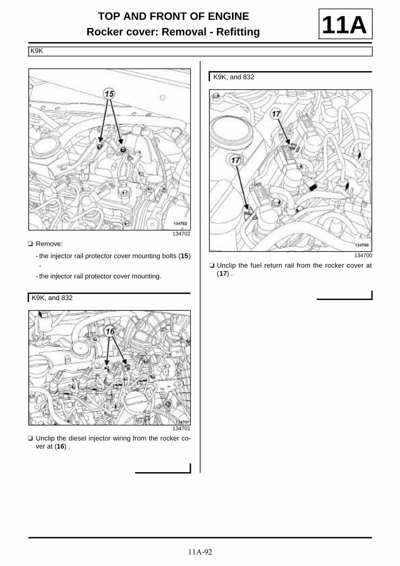
11A-92
TOP AND FRONT OF ENGINERocker cover: Removal - Refitting
K9K
11A
a Remove:
- the injector rail protector cover mounting bolts (15),
- the injector rail protector cover mounting.
a Unclip the diesel injector wiring from the rocker co-ver at (16) .
a Unclip the fuel return rail from the rocker cover at(17) .
134702
K9K, and 832
134701
K9K, and 832
134700

11A-93
TOP AND FRONT OF ENGINERocker cover: Removal - Refitting
K9K
11A
a Unclip the fuel return rail from the rocker cover at(18) .
a Disconnect the oil vapour rebreathing pipe from therocker cover.
II - OPERATION FOR REMOVAL OF PART CONCERNED
a Remove:
- the rocker cover bolts (19) ,
- the rocker cover,
- the rocker cover seal.
a Remove:
- the rocker cover bolts (20) ,
K9K, and 830
135860
K9K, and 832
K9K, and 832
135489
K9K, and 830
135876

11A-94
TOP AND FRONT OF ENGINERocker cover: Removal - Refitting
K9K
11A- the rocker cover,
- the rocker cover seal.
REFITTING
I - REFITTING PREPARATION OPERATION
a parts always to be replaced: Rocker cover gas-ket (10,02,01,12).
a Clean the cylinder head joint face using ABRASIVEPADS.
a Use SURFACE CLEANER (see Vehicle: Parts and ingredients for the repairwork) (04B, Consu-mables - Products) and CLEAN CLOTHS to de-grease:
- the cylinder head joint face,
- the rocker cover seal housing in the rocker cover ifit is to be reused.
a
a Apply four beads (21) of SILICONE ADHESIVESEALANT (see Vehicle: Parts and ingredientsfor the repairwork) (04B, Consumables - Products)2 mm in diameter and 10 mm long.
If replacing the rocker cover
a Remove the camshaft position sensor from the roc-ker cover.
a Refit the camshaft position sensor onto the new roc-ker cover.
WARNING
Do not scrape the joint faces of the aluminium,any damage caused to the joint face will result ina risk of leaks.
WARNING
To ensure proper sealing, the gasket surfacesmust be clean, dry and not greasy (avoid any fin-ger marks).
19712-1
WARNING
Applying excess sealant could cause it to besqueezed out when parts are tightened. A mix-ture of sealant and fluid could damage certaincomponents (engine, radiator, etc.).
K9K, and 832

11A-95
TOP AND FRONT OF ENGINERocker cover: Removal - Refitting
K9K
11AII - REFITTING OPERATION FOR PART CONCERNED
a Refit the rocker cover, fitted with a new gasket.
a Tighten to torque and in order the rocker coverbolts (11 N.m).
III - FINAL OPERATION
a Connect the oil vapour rebreathing pipe onto therocker cover.
a Clip on the rocker cover:
- the fuel return rail,
- the diesel injector wiring.
a Refit:
- the injector rail protector cover mounting,
- the injector rail protector cover.
a Clip the injector rail protector cover into place.
a Refit the damper valve (see 12A, Fuel mixture, Airinlet flap: Removal - Refitting, page 12A-11) .
a Refit the oil vapour rebreathing valve.
a Connect the brake servo pipe onto the vacuumpump.
a Refit the oil vapour rebreathing valve bracket.
a Fit the gearbox breather pipe mounting.
a Refit the nut of the gearbox breather pipe mounting.
a Connect the oil vapour rebreathing pipe to the oil va-pour rebreathing valve.
a Fit the clip of the oil vapour rebreathing pipe on theoil vapour rebreathing valve.
a Connect the oil vapour rebreathing pipe to the air fil-ter box air outlet pipe.
a Refit:
- the turbocharger air outlet pipe (see 12B, Turbo-charging, Intercooler air inlet pipe: Removal -Refitting, page 12B-41) ,
- the upper timing cover.
a Clip on the upper timing cover.
a Refit the upper timing cover bolt.
a Refit:
- the right-hand suspended engine mounting (see19D, Engine mounting, Right-hand suspendedengine mounting: Removal - Refitting, page19D-18) ,
- the scoop under the scuttle panel grille (see Scoopunder scuttle panel grille: Removal - Refitting)(56A, Exterior equipment),
- the scuttle panel grille (see Scuttle panel grille:Removal - Refitting) (56A, Exterior equipment),
- the windscreen wiper arms (see Windscreen wi-per arm: Removal - Refitting) (85A, Wiping -Washing),
- the lower engine tie-bar.
135489
K9K, and 832
K9K, and 832
K9K, and 830
K9K, and 830

11A-96
TOP AND FRONT OF ENGINERocker cover: Removal - Refitting
K9K
11A
a Refit the camshaft position sensor (see 13B, Dieselinjection, Camshaft position sensor: Removal -Refitting, page 13B-19) .
a Tighten to torque:
- the lower engine tie-bar bolt on the subframe(180 N.m),
- the lower engine tie-bar bolt on the lower engi-ne tie-bar support (180 N.m).
a Refit:
- the engine undertray,
- the engine cover.
K9K, and 830

11A-97
TOP AND FRONT OF ENGINERocker cover: Removal - Refitting
K4M
11A
REMOVAL
I - REMOVAL PREPARATION OPERATION
a Position the vehicle on a two-post lift (see Vehicle:Towing and lifting) (02A, Lifting equipment).
a Disconnect the battery (see Battery: Removal - Re-fitting) (80A, Battery).
a Remove:
- the engine cover,
- the throttle valve (see 12A, Fuel mixture, Throttlevalve: Removal - Refitting, page 12A-17) ,
- the windscreen wiper arms (see Windscreen wi-per arm: Removal - Refitting) (85A, Wiping -Washing)
- the scuttle panel grille (see Scuttle panel grille:Removal - Refitting) (56A, Exterior equipment),
- the scoop under the scuttle panel grille (see Scoopunder scuttle panel grille: Removal - Refitting)(56A, Exterior equipment),
- the front right-hand wheel (see Wheel: Removal -Refitting) (35A, Wheels and tyres),
- the front section of the front right-hand wheel archliner (see Front wheel arch liner: Removal - Re-fitting) (55A, Exterior protection),
- the engine undertray bolts,
- the engine undertray,
- the lower engine tie-bar (see 19D, Engine moun-ting, Lower engine tie-bar: Removal - Refitting,page 19D-33) ,
- the accessories belt (see 11A, Top and front ofengine, Accessories belt: Removal - Refitting,page 11A-7) ,
- the right-hand suspended engine mounting (see19D, Engine mounting, Right-hand suspendedengine mounting: Removal - Refitting, page19D-18) ,
- the crankshaft accessories pulley (see 11A, Topand front of engine, Crankshaft accessoriespulley: Removal - Refitting, page 11A-15) ,
- the timing belt (see 11A, Top and front of engine,Timing belt: Removal - Refitting, page 11A-29) ,
- the inlet manifold (see 12A, Fuel mixture, Inletmanifold: Removal - Refitting, page 12A-23) ,
- the ignition coils (see 17A, Ignition, Coils Remo-val - Refitting, page 17A-1) ,
- the oil separator (see 11A, Top and front of engi-ne, Oil decanter: Removal - Refitting, page 11A-205) .
a Remove:
- the camshaft dephaser solenoid valve (see 11A,Top and front of engine, Camshaft dephasersolenoid valve: Removal - Refitting, page 11A-184) ,
- the camshaft position sensor (see 17B, Petrol in-jection, Camshaft position sensor: Removal -Refitting, page 17B-13) .
a Position the tool (Mot. 1490-01) on the camshaftpulleys.
Essential special tooling
Mot. 1490-01 Locking and adjusting cams-haft pulleys.
Tightening torquesm
rocker cover bolts 23,18, 19, and 24
14 N.m
rocker cover bolts 1 to17, 20, 21, and 22
12 N.m
new nut on the exhaustcamshaft sprocket
30 N.m + 84˚ ±±±±4˚
new nut on the inletcamshaft sprocket
30 N.m + 84˚ ±±±±4˚
new bolt on the cams-haft dephaser
100 N.m
K4M, and 858 or 866

11A-98
TOP AND FRONT OF ENGINERocker cover: Removal - Refitting
K4M
11A
a Undo:
- the exhaust camshaft sprocket nut (1) ,
- the inlet camshaft sprocket nut (2) .
a Remove the tool (Mot. 1490-01) from the camshaftsprockets.
a Remove:
- the exhaust camshaft sprocket nut,
- the exhaust camshaft sprocket,
- the inlet camshaft sprocket nut,
- the inlet camshaft sprocket.
a Remove the camshaft dephaser blanking cover (4) .
a Undo:
- the exhaust camshaft sprocket nut (3) ,
- the camshaft dephaser bolt.
a Remove the tool (Mot. 1490-01) from the camshaftsprockets.
a Remove:
- the exhaust camshaft sprocket nut,
- the exhaust camshaft sprocket,
- the camshaft dephaser bolt,
- the camshaft dephaser.
K4M, and 848
135235
K4M, and 858 or 866
136530
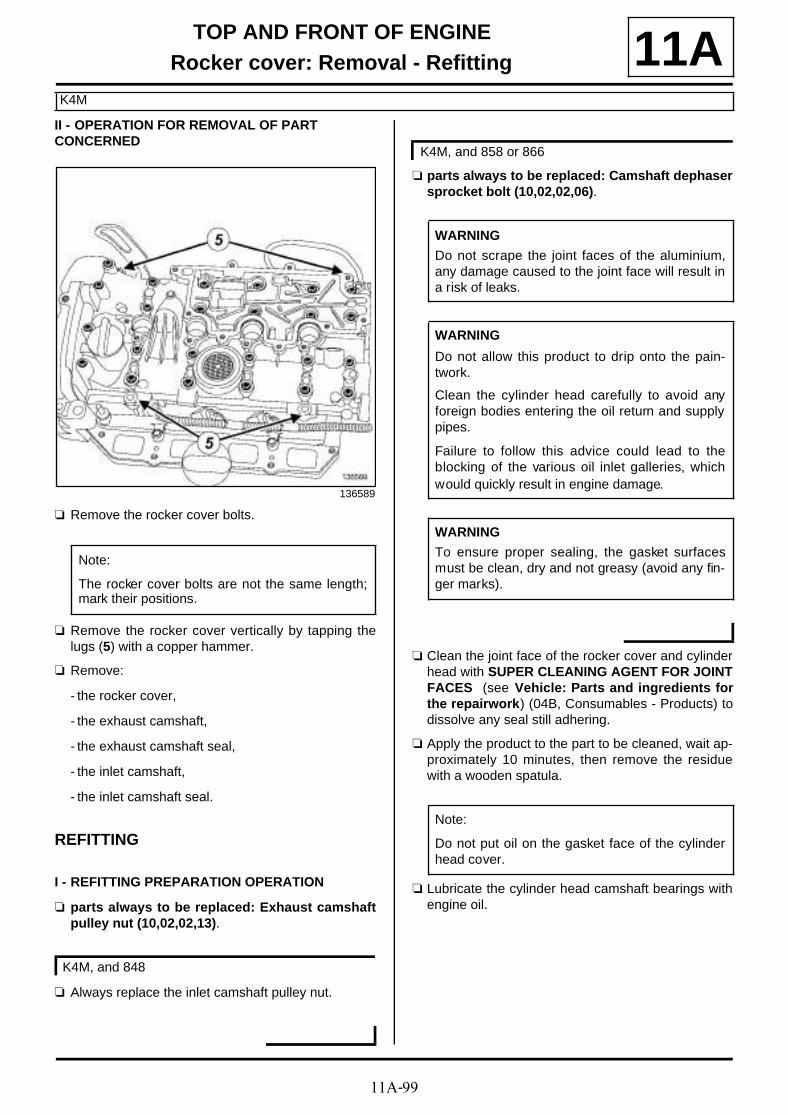
11A-99
TOP AND FRONT OF ENGINERocker cover: Removal - Refitting
K4M
11AII - OPERATION FOR REMOVAL OF PART CONCERNED
a Remove the rocker cover bolts.
a Remove the rocker cover vertically by tapping thelugs (5) with a copper hammer.
a Remove:
- the rocker cover,
- the exhaust camshaft,
- the exhaust camshaft seal,
- the inlet camshaft,
- the inlet camshaft seal.
REFITTING
I - REFITTING PREPARATION OPERATION
a parts always to be replaced: Exhaust camshaftpulley nut (10,02,02,13).
a Always replace the inlet camshaft pulley nut.
a parts always to be replaced: Camshaft dephasersprocket bolt (10,02,02,06).
a Clean the joint face of the rocker cover and cylinderhead with SUPER CLEANING AGENT FOR JOINTFACES (see Vehicle: Parts and ingredients forthe repairwork) (04B, Consumables - Products) todissolve any seal still adhering.
a Apply the product to the part to be cleaned, wait ap-proximately 10 minutes, then remove the residuewith a wooden spatula.
a Lubricate the cylinder head camshaft bearings withengine oil.
136589
Note:
The rocker cover bolts are not the same length;mark their positions.
K4M, and 848
K4M, and 858 or 866
WARNING
Do not scrape the joint faces of the aluminium,any damage caused to the joint face will result ina risk of leaks.
WARNING
Do not allow this product to drip onto the pain-twork.
Clean the cylinder head carefully to avoid anyforeign bodies entering the oil return and supplypipes.
Failure to follow this advice could lead to theblocking of the various oil inlet galleries, whichwould quickly result in engine damage.
WARNING
To ensure proper sealing, the gasket surfacesmust be clean, dry and not greasy (avoid any fin-ger marks).
Note:
Do not put oil on the gasket face of the cylinderhead cover.

11A-100
TOP AND FRONT OF ENGINERocker cover: Removal - Refitting
K4M
11A
a Using a stipple roller, apply RESIN ADHESIVE (seeVehicle: Parts and ingredients for the repai-rwork) (04B, Consumables - Products) to the jointface until it is well coated.
a Use a cloth to remove any RESIN ADHESIVE in therocker cover bearings (6) .
II - REFITTING OPERATION FOR PART CONCERNED
a Refit the camshafts while positioning them correctly(see Upper engine: Specifications) (TechnicalNote 6023A, 10A, Engine and peripherals).
a Refit the rocker cover.
a Tighten the rocker cover bolts in order as illustratedabove.
a Tighten to torque:
- rocker cover bolts 23, 18, 19, and 24 (14 N.m),
- rocker cover bolts 1 to 17, 20, 21, and 22 (12N.m).
III - FINAL OPERATION
a Refit the camshaft timing end seals (see 11A, Topand front of engine, Camshaft seal at timing end:Removal - Refitting, page 11A-186) .
a Refit:
- the inlet camshaft sprocket,
- a new nut on the inlet camshaft sprocket,
- the exhaust camshaft sprocket,
- a new nut on the exhaust camshaft sprocket,
14517
126216
WARNING
Applying excess sealant could cause it to besqueezed out when parts are tightened. A mix-ture of sealant and fluid could damage certaincomponents (engine, radiator, etc.).
136589
K4M, and 848

11A-101
TOP AND FRONT OF ENGINERocker cover: Removal - Refitting
K4M
11A
a Refit:
- the camshaft dephaser,
- a new bolt on the camshaft dephaser,
- the exhaust camshaft sprocket,
- a new nut on the exhaust camshaft sprocket,
a Position the tool (Mot. 1490-01) on the camshaftsprockets.
a Torque tighten the new nut on the exhaust cams-haft sprocket (30 N.m + 84˚ ±±±± 4˚).
a Torque tighten the new nut on the inlet camshaftsprocket (30 N.m + 84˚ ±±±± 4˚).
a Torque tighten the new bolt on the camshaft de-phaser (100 N.m).
a Refit the camshaft dephaser blanking cover.
a Remove the tool (Mot. 1490-01) from the camshaftsprockets.
a Refit:
- the camshaft position sensor (see 17B, Petrol in-jection, Camshaft position sensor: Removal -Refitting, page 17B-13) ,
- the camshaft dephaser solenoid valve (see 11A,Top and front of engine, Camshaft dephasersolenoid valve: Removal - Refitting, page 11A-184) .
a Refit:
- the oil separator (see 11A, Top and front of engi-ne, Oil decanter: Removal - Refitting, page 11A-205) ,
- the ignition coils (see 17A, Ignition, Coils Remo-val - Refitting, page 17A-1) ,
- the inlet manifold (see 12A, Fuel mixture, Inletmanifold: Removal - Refitting, page 12A-23) ,
- the timing belt (see 11A, Top and front of engine,Timing belt: Removal - Refitting, page 11A-29) ,
- the crankshaft accessories pulley (see 11A, Topand front of engine, Crankshaft accessoriespulley: Removal - Refitting, page 11A-15) ,
- the right-hand suspended engine mounting (see19D, Engine mounting, Right-hand suspendedengine mounting: Removal - Refitting, page19D-18) ,
- the accessories belt (see 11A, Top and front ofengine, Accessories belt: Removal - Refitting,page 11A-7) ,
- the lower engine tie-bar (see 19D, Engine moun-ting, Lower engine tie-bar: Removal - Refitting,page 19D-33) ,
- the engine undertray,
- the front section of the front right-hand wheel archliner (see Front wheel arch liner: Removal - Re-fitting) (55A, Exterior protection),
- the front right-hand wheel (see Wheel: Removal -Refitting) (35A, Wheels and tyres),
- the scoop under the scuttle panel grille (see Scoopunder scuttle panel grille: Removal - Refitting)(56A, Exterior equipment),
- the scuttle panel grille (see Scuttle panel grille:Removal - Refitting) (56A, Exterior equipment),
- the windscreen wiper arms (see Windscreen wi-per arm: Removal - Refitting) (85A, Wiping -Washing)
- the throttle valve (see 12A, Fuel mixture, Throttlevalve: Removal - Refitting, page 12A-17) ,
- the engine cover.
a Connect the battery (see Battery: Removal - Refit-ting) (80A, Battery).
K4M, and 858 or 866
K4M, and 848
K4M, and 858 or 866
K4M, and 858 or 866

11A-102
TOP AND FRONT OF ENGINERocker cover: Removal - Refitting
F4R
11A
REMOVAL
I - REMOVAL PREPARATION OPERATION
a Position the vehicle on a two-post lift (see Vehicle:Towing and lifting) (02A, Lifting equipment).
a Remove:
- the engine cover,
- the battery (see Battery : Removal - Refitting)(80A, Battery),
- the battery tray (see Battery tray: Removal - Re-fitting) (80A, Battery),
- the windscreen wiper arms (see Scuttle panelgrille: Removal - Refitting) (85A, Wiping -Washing),
- the scuttle panel grille (see Scuttle panel grille:Removal - Refitting) (56A, Exterior equipment),
- the scoop under the scuttle panel grille (see Scoopunder scuttle panel grille: Removal - Refitting)(56A, Exterior equipment),
- the ignition coils (see 17A, Ignition, Coils Remo-val - Refitting, page 17A-1) .
a Remove the retaining bolts (1) of the intercooler airinlet pipe.
Essential special tooling
Mot. 1453 Multiple-adjusting enginemounting support with retai-ning straps.
Mot. 1453-01 Additional winder nut onengine lift support Mot. 1453.
Mot. 1390 Support for removing/refittingthe engine - gearbox assem-bly.
Mot. 1716 Removes housing with sili-cone seals.
Essential equipment
safety strap(s)
Tightening torquesm
rocker cover bolts (22),(23), (20), (13)
8 N.m
rocker cover bolts (1) to(12), (14) to (19), (21),(24)
12 N.m
rocker cover bolts (22),(23), (20), (13)
12 N.m
catalytic converter strutnut
44 N.m
catalytic converter strutbolt
8 N.m
clip for the intercoolerair inlet pipe
6 N.m
138084
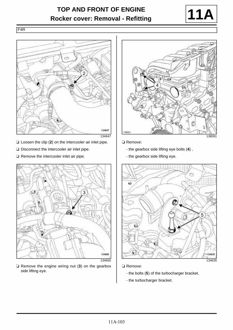
11A-103
TOP AND FRONT OF ENGINERocker cover: Removal - Refitting
F4R
11A
a Loosen the clip (2) on the intercooler air inlet pipe.
a Disconnect the intercooler air inlet pipe.
a Remove the intercooler inlet air pipe.
a Remove the engine wiring nut (3) on the gearboxside lifting eye.
a Remove:
- the gearbox side lifting eye bolts (4) ,
- the gearbox side lifting eye.
a Remove:
- the bolts (5) of the turbocharger bracket,
- the turbocharger bracket.
134647
134650
138091
134635

11A-104
TOP AND FRONT OF ENGINERocker cover: Removal - Refitting
F4R
11A
a Unclip the oil vapour rebreathing pipe at (6) .
a Remove the oil vapour rebreathing pipe.
a Remove:
- the bolts (7) from the turbocharger heat shield,
- the turbocharger heat shield.
a Disconnect:
- the upstream oxygen sensor connector (8) ,
- the camshaft position sensor connector (9) ,
- the oil vapour recirculation solenoid valve connec-tor (10) ,
- the air pressure sensor connector on the inlet ma-nifold (11) ,
- the air temperature sensor connector on the inter-cooler air outlet pipe (12) ,
- the air pressure sensor connector on the intercoo-ler air outlet pipe (13) ,
- the petrol injector connectors (14) .
a Move aside the engine wiring.
134643
134649
WARNING
To prevent the surrounding components fromoverheating, do not damage (tear, pierce, bend,etc.) a heat shield.
Any damaged heat shields must be replaced.
134642
134642

11A-105
TOP AND FRONT OF ENGINERocker cover: Removal - Refitting
F4R
11A
a Disconnect the oil vapour rebreathing pipe at (15) .
a Remove the oil vapour rebreathing pipe.
a Disconnect the petrol vapour rebreathing pipe at(16) .
a Disconnect the petrol vapour rebreathing pipe at(17) .
a Remove the petrol vapour rebreathing pipe.
a Disconnect the fuel supply pipe at (18) .
135744
134645
134636
134637

11A-106
TOP AND FRONT OF ENGINERocker cover: Removal - Refitting
F4R
11A
a Unclip the fuel supply pipe at (19) .
a Move aside the fuel supply pipe.
a Remove:
- the bolts (20) of the oil vapour rebreathing rigid pi-pe,
- the oil vapour rebreathing rigid pipe,
- the front wheels (see Wheel: Removal - Refitting)(35A, Wheels and tyres),
- the front section of the front wheel arch liners (seeFront wheel arch liner: Removal - Refitting)(55A, Exterior protection),
- the front bumper (see Front bumper: Removal -Refitting) (55A, Exterior protection),
- the radiator mounting cross member (see Radiatorsupport cross member: Removal - Refitting)(31A, Front axle components),
a Drain the manual gearbox (see Manual gearboxoil: Draining - Refilling) (21A, Manual gearbox).
a Remove:
- the front right-hand driveshaft (see Front right-hand wheel driveshaft: Removal - Refitting)(29A, Driveshafts),
- the right-hand differential output seal (see Diffe-rential output seal: Removal - Refitting) (21A,Manual gearbox),
- the lower engine tie-bar (see 19D, Engine moun-ting, Lower engine tie-bar: Removal - Refitting,page 19D-33) .
a Remove:
- the lower engine tie-bar support bolts (21) on thesump,
- the lower engine tie-bar support on the sump.
134644
134639
136504
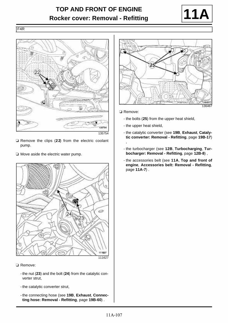
11A-107
TOP AND FRONT OF ENGINERocker cover: Removal - Refitting
F4R
11A
a Remove the clips (22) from the electric coolantpump.
a Move aside the electric water pump.
a Remove:
- the nut (23) and the bolt (24) from the catalytic con-verter strut,
- the catalytic converter strut,
- the connecting hose (see 19B, Exhaust, Connec-ting hose: Removal - Refitting, page 19B-60) .
a Remove:
- the bolts (25) from the upper heat shield,
- the upper heat shield,
- the catalytic converter (see 19B, Exhaust, Cataly-tic converter: Removal - Refitting, page 19B-17),
- the turbocharger (see 12B, Turbocharging, Tur-bocharger: Removal - Refitting, page 12B-8) ,
- the accessories belt (see 11A, Top and front ofengine, Accessories belt: Removal - Refitting,page 11A-7) .
135754
111627
136467
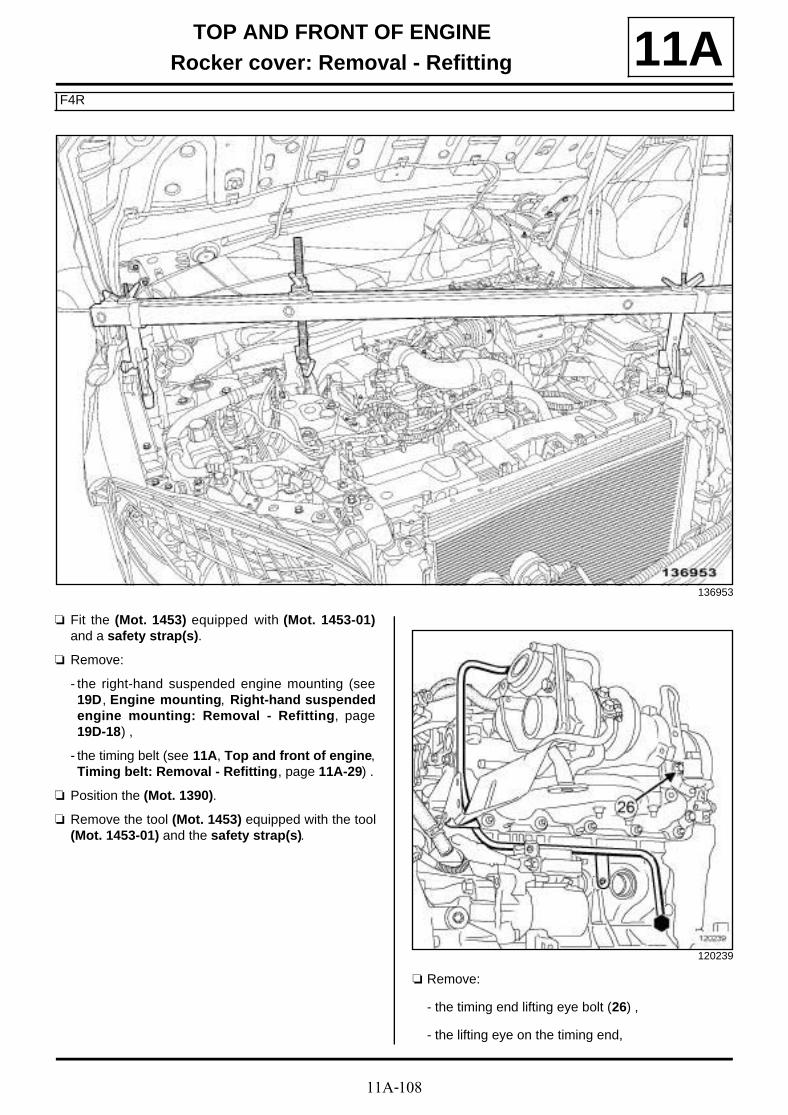
11A-108
TOP AND FRONT OF ENGINERocker cover: Removal - Refitting
F4R
11A
a Fit the (Mot. 1453) equipped with (Mot. 1453-01)and a safety strap(s).
a Remove:
- the right-hand suspended engine mounting (see19D, Engine mounting, Right-hand suspendedengine mounting: Removal - Refitting, page19D-18) ,
- the timing belt (see 11A, Top and front of engine,Timing belt: Removal - Refitting, page 11A-29) .
a Position the (Mot. 1390).
a Remove the tool (Mot. 1453) equipped with the tool(Mot. 1453-01) and the safety strap(s).
a Remove:
- the timing end lifting eye bolt (26) ,
- the lifting eye on the timing end,
136953
120239
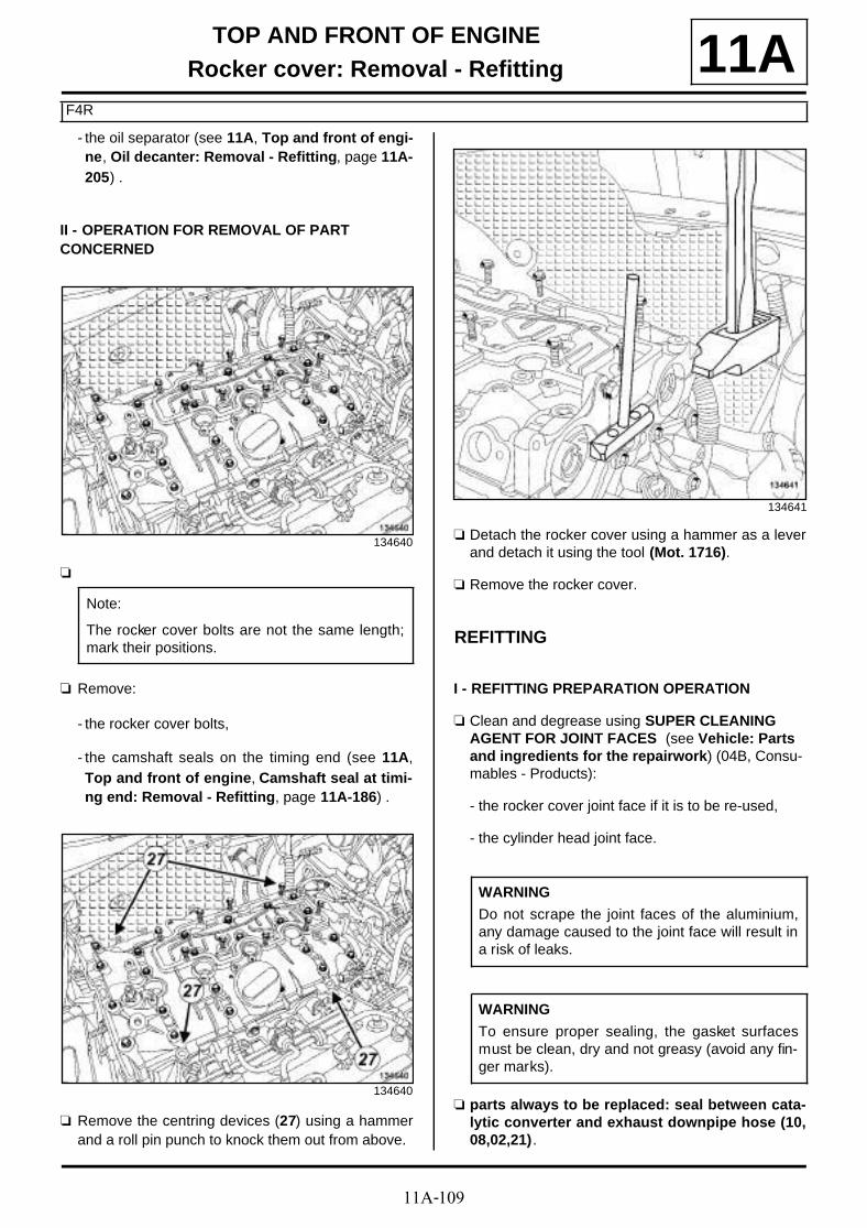
11A-109
TOP AND FRONT OF ENGINERocker cover: Removal - Refitting
F4R
11A- the oil separator (see 11A, Top and front of engi-ne, Oil decanter: Removal - Refitting, page 11A-205) .
II - OPERATION FOR REMOVAL OF PART CONCERNED
a
a Remove:
- the rocker cover bolts,
- the camshaft seals on the timing end (see 11A,Top and front of engine, Camshaft seal at timi-ng end: Removal - Refitting, page 11A-186) .
a Remove the centring devices (27) using a hammerand a roll pin punch to knock them out from above.
a Detach the rocker cover using a hammer as a leverand detach it using the tool (Mot. 1716).
a Remove the rocker cover.
REFITTING
I - REFITTING PREPARATION OPERATION
a Clean and degrease using SUPER CLEANING AGENT FOR JOINT FACES (see Vehicle: Parts and ingredients for the repairwork) (04B, Consu-mables - Products):
- the rocker cover joint face if it is to be re-used,
- the cylinder head joint face.
a parts always to be replaced: seal between cata-lytic converter and exhaust downpipe hose (10,08,02,21).
134640
Note:
The rocker cover bolts are not the same length;mark their positions.
134640
134641
WARNING
Do not scrape the joint faces of the aluminium,any damage caused to the joint face will result ina risk of leaks.
WARNING
To ensure proper sealing, the gasket surfacesmust be clean, dry and not greasy (avoid any fin-ger marks).

11A-110
TOP AND FRONT OF ENGINERocker cover: Removal - Refitting
F4R
11A
a
a Apply RESIN ADHESIVE (see Vehicle: Parts andingredients for the repairwork) (04B, Consuma-bles - Products) using a stipple roller on the jointface of the rocker cover until the joint face is comple-tely coated.
a Use a cloth to remove any RESIN ADHESIVE on therocker cover bearings.
a Refit the centring devices of the rocker cover using aroll pin punch and a hammer.
II - REFITTING OPERATION FOR PART CONCERNED
a Refit the rocker cover.
a Fit without tightening the rocker cover bolts.
a Tighten to torque and in order:
- the rocker cover bolts (22), (23), (20), (13) (8N.m),
- the rocker cover bolts (1) to (12), (14) to (19),(21), (24) (12 N.m),
- the rocker cover bolts (22), (23), (20), (13) (12N.m).
III - FINAL OPERATION
a Refit:
- new camshaft timing end seals (see 11A, Top andfront of engine, Camshaft seal at timing end:Removal - Refitting, page 11A-186) ,
- the oil separator (see 11A, Top and front of engi-ne, Oil decanter: Removal - Refitting, page 11A-205) ,
- the lifting eye on the timing end.
a Fit the tool (Mot. 1453) equipped with the tool (Mot.1453-01) and the safety strap(s).
a Remove the (Mot. 1390).
a Refit:
- the timing belt (see 11A, Top and front of engine,Timing belt: Removal - Refitting, page 11A-29) ,
- the right-hand suspended engine mounting (see19D, Engine mounting, Right-hand suspendedengine mounting: Removal - Refitting, page19D-18) ,
- the accessories belt (see 11A, Top and front ofengine, Accessories belt: Removal - Refitting,page 11A-7) ,
- the turbocharger (see 12B, Turbocharging, Tur-bocharger: Removal - Refitting, page 12B-8) ,
14517
WARNING
Applying excess sealant could cause it to besqueezed out when parts are tightened. A mix-ture of sealant and fluid could damage certaincomponents (engine, radiator, etc.).
120210

11A-111
TOP AND FRONT OF ENGINERocker cover: Removal - Refitting
F4R
11A- the catalytic converter (see 19B, Exhaust, Cataly-tic converter: Removal - Refitting, page 19B-17),
- the upper heat shield,
- the connecting hose (see 19B, Exhaust, Connec-ting hose: Removal - Refitting, page 19B-60) ,
- the catalytic converter strut,
a Tighten to torque:
- the catalytic converter strut nut (44 N.m),
- the catalytic converter strut bolt (8 N.m).
a Fit the electric coolant pump.
a Refit:
- the electric coolant pump clips,
- the lower engine tie-bar support on the sump,
- the lower engine tie-bar (see 19D, Engine moun-ting, Lower engine tie-bar: Removal - Refitting,page 19D-33) ,
- a right-hand differential output seal (see Differenti-al output seal: Removal - Refitting) (21A, Manualgearbox),
- the front right-hand wheel driveshaft (see Front ri-ght-hand wheel driveshaft: Removal - Refitting)(29A, Driveshafts),
a Fill the manual gearbox (see Manual gearbox oil:Draining - Refilling) (21A, Manual gearbox).
a Refit:
- the radiator mounting cross member (see Radiatorsupport cross member: Removal - Refitting)(31A, Front axle components),
- the front bumper (see Front bumper: Removal -Refitting) (55A, Exterior protection),
- the front section of the front wheel arch liners (seeFront wheel arch liner: Removal - Refitting)(55A, Exterior protection),
- the front wheels (see Wheel: Removal - Refitting)(35A, Wheels and tyres),
- the oil vapour rebreathing rigid pipe,
a Connect the fuel supply pipe.
a Clip on the fuel supply pipe.
a Refit the fuel vapour rebreathing pipes.
a Connect the fuel vapour rebreathing pipes.
a Fit the wiring on the engine.
a Connect:
- the petrol injector connectors,
- the air pressure sensor connector on the intercoo-ler air outlet pipe,
- the air temperature sensor connector on the inter-cooler air outlet pipe,
- the air pressure sensor connector on the inlet ma-nifold,
- the oil vapour recirculation solenoid valve connec-tor,
- the camshaft position sensor connector,
- the upstream oxygen sensor connector.
a Refit:
- the turbocharger heat shield,
- the oil vapour rebreathing pipe .
a Clip on the oil vapour rebreathing pipe.
a Refit:
- the turbocharger bracket,
- the gearbox side lifting eye,
- the engine wiring nut onto the lifting eye.
a Connect the intercooler air inlet pipe.
a Torque tighten the clip for the intercooler air inletpipe (6 N.m).
a Refit:
- the retaining bolts of the intercooler air inlet pipe,
- the ignition coils (see 17A, Ignition, Coils Remo-val - Refitting, page 17A-1) ,
- the scoop under the scuttle panel grille (see Scoopunder scuttle panel grille: Removal - Refitting)(56A, Exterior equipment),
- the scuttle panel grille (see Scuttle panel grille:Removal - Refitting) (56A, Exterior equipment),
- the windscreen wiper arms (see Windscreen wi-per arm: Removal - Refitting) (85A, Wiping -Washing),
- the battery tray (see Battery tray: Removal - Re-fitting) (80A, Battery),
- the battery (see Battery : Removal - Refitting)(80A, Battery),
- the engine cover.
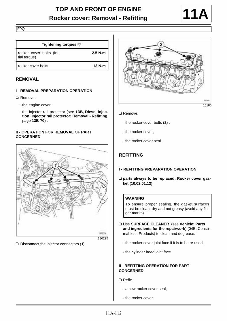
11A-112
TOP AND FRONT OF ENGINERocker cover: Removal - Refitting
F9Q
11A
REMOVAL
I - REMOVAL PREPARATION OPERATION
a Remove:
- the engine cover,
- the injector rail protector (see 13B, Diesel injec-tion, Injector rail protector: Removal - Refitting,page 13B-70) .
II - OPERATION FOR REMOVAL OF PART CONCERNED
a Disconnect the injector connectors (1) .
a Remove:
- the rocker cover bolts (2) ,
- the rocker cover,
- the rocker cover seal.
REFITTING
I - REFITTING PREPARATION OPERATION
a parts always to be replaced: Rocker cover gas-ket (10,02,01,12).
a Use SURFACE CLEANER (see Vehicle: Parts and ingredients for the repairwork) (04B, Consu-mables - Products) to clean and degrease:
- the rocker cover joint face if it is to be re-used,
- the cylinder head joint face.
II - REFITTING OPERATION FOR PART CONCERNED
a Refit:
- a new rocker cover seal,
- the rocker cover.
Tightening torquesm
rocker cover bolts (ini-tial torque)
2.5 N.m
rocker cover bolts 13 N.m
136225
16186
WARNING
To ensure proper sealing, the gasket surfacesmust be clean, dry and not greasy (avoid any fin-ger marks).

11A-113
TOP AND FRONT OF ENGINERocker cover: Removal - Refitting
F9Q
11A
a Pretighten to torque and in order the rocker coverbolts (initial torque) (2.5 N.m).
a Torque tighten in order the rocker cover bolts (13N.m).
a Connect the injector connectors.
III - FINAL OPERATION
a Refit:
- the injector rail protector (see 13B, Diesel injec-tion, Injector rail protector: Removal - Refitting,page 13B-70) ,
- the engine cover.
16186

11A-114
TOP AND FRONT OF ENGINECamshaft: Removal - Refitting
K4M
11AREMOVAL
I - REMOVAL PREPARATION OPERATION
a Position the vehicle on a two-post lift (see Vehicle:Towing and lifting) (02A, Lifting equipment).
a Disconnect the battery (see Battery: Removal - Re-fitting) (80A, Battery).
a Remove:
- the engine cover,
- the throttle valve (see 12A, Fuel mixture, Throttlevalve: Removal - Refitting, page 12A-17) ,
- the windscreen wiper arms (see Windscreen wi-per arm: Removal - Refitting) (85A, Wiping -Washing),
- the scuttle panel grille (see Scuttle panel grille:Removal - Refitting) (56A, Exterior equipment),
- the scoop under the scuttle panel grille (see Scoopunder scuttle panel grille: Removal - Refitting)(56A, Exterior equipment),
- the front right-hand wheel (see Wheel: Removal -Refitting) (35A, Wheels and tyres),
- the front section of the front right-hand wheel archliner (see Front wheel arch liner: Removal - Re-fitting) (55A, Exterior protection),
- the engine undertray bolts,
- the engine undertray,
- the lower engine tie-bar (see 19D, Engine moun-ting, Lower engine tie-bar: Removal - Refitting,page 19D-33) ,
- the accessories belt (see 11A, Top and front ofengine, Accessories belt: Removal - Refitting,page 11A-7) ,
- the right-hand suspended engine mounting (see19D, Engine mounting, Right-hand suspendedengine mounting: Removal - Refitting, page19D-18) ,
- the crankshaft accessories pulley (see 11A, Topand front of engine, Crankshaft accessoriespulley: Removal - Refitting, page 11A-15) ,
- the timing belt (see 11A, Top and front of engine,Timing belt: Removal - Refitting, page 11A-29) ,
- the inlet manifold (see 12A, Fuel mixture, Inletmanifold: Removal - Refitting, page 12A-23) ,
- the ignition coils (see 17A, Ignition, Coils Remo-val - Refitting, page 17A-1) ,
- the oil separator (see 11A, Top and front of engi-ne, Oil decanter: Removal - Refitting, page 11A-205) ,
a Remove the camshaft pulleys.
a Remove:
- the camshaft dephaser solenoid valve (see 11A,Top and front of engine, Camshaft dephasersolenoid valve: Removal - Refitting, page 11A-184) ,
- the camshaft position sensor (see 17B, Petrol in-jection, Camshaft position sensor: Removal -Refitting, page 17B-13) ,
- the camshaft dephaser (see 11A, Top and front ofengine, Camshaft dephaser: Removal - Refit-ting, page 11A-177) ,
- the exhaust camshaft pulley.
a Remove:
- the rocker cover (see 11A, Top and front of engi-ne, Rocker cover: Removal - Refitting, page11A-88) ,
- the camshaft timing end seals (see 11A, Top andfront of engine, Camshaft seal at timing end:Removal - Refitting, page 11A-186) .
K4M, and 848
K4M, and 858 or 866

11A-115
TOP AND FRONT OF ENGINECamshaft: Removal - Refitting
K4M
11AII - OPERATION FOR REMOVAL OF PART CONCERNED
a Remove:
- the inlet camshaft (1) ,
- the exhaust camshaft (2) .
a Remove:
- the valve rockers (3) ;
- the hydraulic tappets (4) .
REFITTING
I - REFITTING PREPARATION OPERATION
a Refit the camshafts while positioning them correctly(see Upper engine: Specifications) (TechnicalNote 6023A, 10A, Engine and peripherals).
a Always replace the studs of the inlet and exhaustcamshafts if the stud loosens along with the nut ofthe inlet or exhaust camshaft (see 11A, Top andfront of engine, Camshaft: Removal - Refitting,page 11A-114) (Technical Note 3887A, 11A, Topand front of engine).
a To check if re-priming is necessary, press the top ofthe tappet with your thumb. If the tappet piston de-presses, immerse the tappets in a container full ofdiesel then reprime them.
II - REFITTING OPERATION FOR PART CONCERNED
a Refit:
- the hydraulic thrust bearings,
- the valve rockers,
- the inlet camshaft, by lubricating the inlet camshaftbearings,
- the exhaust camshaft, by lubricating the exhaustcamshaft bearings.
III - FINAL OPERATION
a Refit:
- the rocker cover (see 11A, Top and front of engi-ne, Rocker cover: Removal - Refitting, page11A-88) ,
- the camshaft timing end seals (see 11A, Top andfront of engine, Camshaft seal at timing end:Removal - Refitting, page 11A-186) .
a Refit:
- the exhaust camshaft pulley.
- the camshaft dephaser (see 11A, Top and front ofengine, Camshaft dephaser: Removal - Refit-ting, page 11A-177) ,
134576
14499
Note:
To prevent any risk of unpriming the hydraulictappets make sure that they are vertical.
Note:
It is essential to reprime the hydraulic tappets asthese may become drained if removed for a longtime.
K4M, and 858 or 866

11A-116
TOP AND FRONT OF ENGINECamshaft: Removal - Refitting
K4M
11A- the camshaft position sensor (see 17B, Petrol in-jection, Camshaft position sensor: Removal -Refitting, page 17B-13) ,
- the camshaft dephaser solenoid valve (see 11A,Top and front of engine, Camshaft dephasersolenoid valve: Removal - Refitting, page 11A-184) .
a Refit the camshaft pulleys.
a Refit:
- the oil separator (see 11A, Top and front of engi-ne, Oil decanter: Removal - Refitting, page 11A-205) ,
- the ignition coils (see 17A, Ignition, Coils Remo-val - Refitting, page 17A-1) ,
- the inlet manifold (see 12A, Fuel mixture, Inletmanifold: Removal - Refitting, page 12A-23) ,
- the timing belt (see 11A, Top and front of engine,Timing belt: Removal - Refitting, page 11A-29) ,
- the crankshaft accessories pulley (see 11A, Topand front of engine, Crankshaft accessoriespulley: Removal - Refitting, page 11A-15) ,
- the right-hand suspended engine mounting (see19D, Engine mounting, Right-hand suspendedengine mounting: Removal - Refitting, page19D-18) ,
- the accessories belt (see 11A, Top and front ofengine, Accessories belt: Removal - Refitting,page 11A-7) ,
- the lower engine tie-bar (see 19D, Engine moun-ting, Lower engine tie-bar: Removal - Refitting,page 19D-33) ,
- the engine undertray,
- the front section of the front right-hand wheel archliner (see Front wheel arch liner: Removal - Re-fitting) (55A, Exterior protection),
- the front right-hand wheel (see Wheel: Removal -Refitting) (35A, Wheels and tyres),
- the scoop under the scuttle panel grille (see Scoopunder scuttle panel grille: Removal - Refitting)(56A, Exterior equipment),
- the scuttle panel grille (see Scuttle panel grille:Removal - Refitting) (56A, Exterior equipment),
- the windscreen wiper arms (see Windscreen wi-per arm: Removal - Refitting) (85A, Wiping -Washing),
- the throttle valve (see 12A, Fuel mixture, Throttlevalve: Removal - Refitting, page 12A-17) ,
- the engine cover.
a Connect the battery (see Battery: Removal - Refit-ting) (80A, Battery).
K4M, and 848

11A-117
TOP AND FRONT OF ENGINECamshaft: Removal - Refitting
K9K
11A
REMOVAL
I - REMOVAL PREPARATION OPERATION
a Position the vehicle on a two-post lift (see Vehicle:Towing and lifting) (02A, Lifting equipment).
a Disconnect the battery (see Battery : Removal -Refitting) (80A, Battery).
a Remove:
- the engine cover,
- the front right-hand wheel (see Wheel: Removal -Refitting) (35A, Wheels and tyres),
- the front section of the front right-hand wheel archliner (see Front wheel arch liner: Removal - Re-fitting) (55A, Exterior protection),
- the engine undertray bolts,
- the engine undertray,
- the accessories belt (see 11A, Top and front ofengine, Accessories belt: Removal - Refitting,page 11A-7) .
- the crankshaft accessories pulley (see 11A, Topand front of engine, Crankshaft accessoriespulley: Removal - Refitting, page 11A-15) ,
- the windscreen wiper arms (see Windscreen wi-per arm: Removal - Refitting) (85A, Wiping -Washing),
- the scuttle panel grille (see Scuttle panel grille:Removal - Refitting) (56A, Exterior equipment),
- the scoop under the scuttle panel grille (see Scoopunder scuttle panel grille: Removal - Refitting)(56A, Exterior equipment),
- the right-hand suspended engine mounting (see19D, Engine mounting, Right-hand suspendedengine mounting: Removal - Refitting, page19D-18) .
a Remove the camshaft position sensor (see 13B,Diesel injection, Camshaft position sensor: Re-moval - Refitting, page 13B-19) .
a Remove:
- the timing belt (see 11A, Top and front of engine,Timing belt: Removal - Refitting, page 11A-29) ,
- the turbocharger air outlet pipe (see 12B, Turbo-charging, Intercooler air inlet pipe: Removal -Refitting, page 12B-41) .
a Remove the damper valve (see 12A, Fuel mixture,Air inlet flap: Removal - Refitting, page 12A-11) .
Essential special tooling
Mot. 1606 High pressure pump-pulleyretaining tool.
Tightening torquesm
bolts of the camshaftbearings
10 N.m
camshaft pulley hubbolts
14 N.m
camshaft pulley nut 30 N.m + 86˚ ±±±±6˚
rocker cover bolts 11 N.m
K9K, and 830
K9K, and 832

11A-118
TOP AND FRONT OF ENGINECamshaft: Removal - Refitting
K9K
11A
a Disconnect the oil vapour rebreathing pipe from theair filter unit air outlet pipe at (1) .
a Separate the clip (2) of the oil vapour rebreathingpipe on the oil vapour rebreathing valve.
a Disconnect the oil vapour rebreathing pipe from theoil vapour rebreathing valve.
a Remove the nut (3) from the gearbox breather pipemounting.
a Move aside the gearbox breather pipe mounting.
a Remove:
- the bolts (4) of the oil vapour rebreathing valve
K9K, and 830
135880
135879
135845
112325
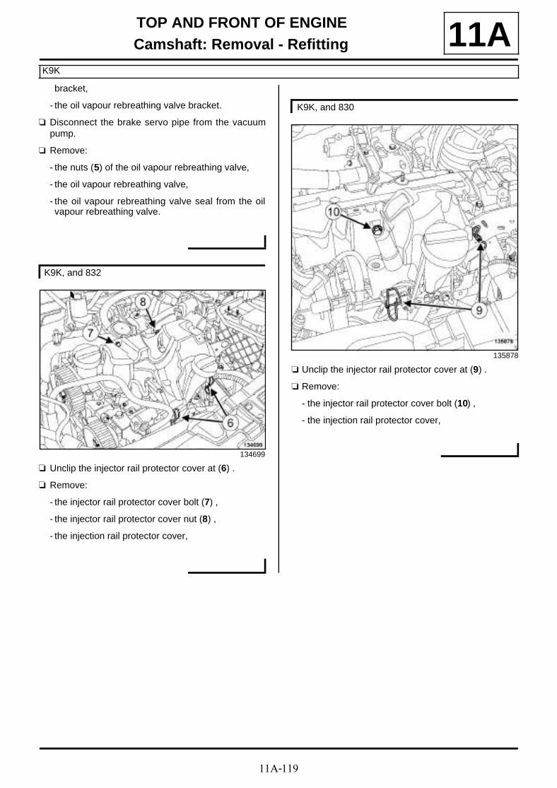
11A-119
TOP AND FRONT OF ENGINECamshaft: Removal - Refitting
K9K
11Abracket,
- the oil vapour rebreathing valve bracket.
a Disconnect the brake servo pipe from the vacuumpump.
a Remove:
- the nuts (5) of the oil vapour rebreathing valve,
- the oil vapour rebreathing valve,
- the oil vapour rebreathing valve seal from the oilvapour rebreathing valve.
a Unclip the injector rail protector cover at (6) .
a Remove:
- the injector rail protector cover bolt (7) ,
- the injector rail protector cover nut (8) ,
- the injection rail protector cover,
a Unclip the injector rail protector cover at (9) .
a Remove:
- the injector rail protector cover bolt (10) ,
- the injection rail protector cover,
K9K, and 832
134699
K9K, and 830
135878

11A-120
TOP AND FRONT OF ENGINECamshaft: Removal - Refitting
K9K
11A
a Remove:
- the injector rail protector cover mounting bolts (11),
- the injector rail protector cover mounting.
a Unclip the diesel injector wiring from the rocker co-ver at (12) .
a Unclip the fuel return rail from the rocker cover at(13) .
134702
K9K, and 832
134701
K9K, and 832
134700

11A-121
TOP AND FRONT OF ENGINECamshaft: Removal - Refitting
K9K
11A
a Unclip the fuel return rail from the rocker cover at(14) .
a Disconnect the oil vapour rebreathing pipe from therocker cover.
a Remove:
- the rocker cover bolts (15) ,
- the rocker cover,
- the rocker cover seal.
a Remove:
- the rocker cover bolts (16) ,
- the rocker cover,
K9K, and 830
135860
K9K, and 832
K9K, and 832
135489
K9K, and 830
135876

11A-122
TOP AND FRONT OF ENGINECamshaft: Removal - Refitting
K9K
11A- the rocker cover seal.
a Remove the vacuum pump (see Vacuum pump:Removal - Refitting) (37A, Mechanical componentcontrols).
a Increase the hole (17) of the (Mot. 1606) (18) usingan 8.5 mm drill bit.
a Undo the camshaft pulley hub bolts (19) .
a Fit the (Mot. 1606) on the cylinder head to lock thecamshaft pulley wheel.
a Tighten the camshaft pulley hub bolts (19) .
a Remove:
- the nut (20) from the camshaft pulley,
- the (Mot. 1606),
- the camshaft pulley.
118982
118983

11A-123
TOP AND FRONT OF ENGINECamshaft: Removal - Refitting
K9K
11AII - OPERATION FOR REMOVAL OF PART CONCERNED
a Mark the position of the camshaft bearings.
a Remove:
- the camshaft bearings bolts (21) ,
- the camshaft bearings,
- the camshaft,
- the timing end camshaft seal.
REFITTING
I - REFITTING PREPARATION OPERATION
a parts always to be replaced: Rocker cover gas-ket (10,02,01,12).
a parts always to be replaced: Camshaft seal on ti-ming end (10,02,02,02).
a parts always to be replaced: Camshaft timingsprocket nut (10,02,02,18).
a Using ABRASIVE PADS clean the load-bearing sur-faces of the camshaft bearings.
a Use SURFACE CLEANER (see Vehicle: Parts and ingredients for the repairwork) to clean and degrease:
- the bearing faces of the camshaft bearings on thecylinder head,
- the bearing faces of the camshaft bearings on thecamshaft bearings,
- the rocker cover seal housing in the rocker cover,
- the rocker cover joint face on the cylinder head.
a Apply four beads (22) of RESIN ADHESIVE (seeVehicle: Parts and ingredients for the repai-rwork) (04B, Consumables - Products) 7 mm in dia-meter on the cylinder head.
II - REFITTING OPERATION FOR PART CONCERNED
a Position the camshaft by positioning the timing endcamshaft groove vertically.
113563
113565
WARNING
To ensure proper sealing, the gasket surfacesmust be clean, dry and not greasy (avoid any fin-ger marks).
WARNING
Applying excess sealant could cause it to besqueezed out when parts are tightened. A mix-ture of sealant and fluid could damage certaincomponents (engine, radiator, etc.).
WARNING
Do not scrape the joint faces of the aluminium,any damage caused to the joint face will result ina risk of leaks.
20064-1

11A-124
TOP AND FRONT OF ENGINECamshaft: Removal - Refitting
K9K
11Aa Refit the camshaft bearings.
a Refit the camshaft bearing bolts (1) , (3) , (4) and (2)in order.
a Tighten the camshaft bearing bolts (1) , (3) , (4) and(2) in order.
a Refit the camshaft bearing bolts in order.
a Tighten to torque and in order the bolts of thecamshaft bearings (10 N.m).
III - FINAL OPERATION
a Refit the camshaft seal (see 11A, Top and front ofengine, Camshaft seal at timing end: Removal -Refitting, page 11A-186) .
a Fit the camshaft pulley.
a Refit a new camshaft pulley nut.
a Undo the camshaft pulley hub bolts (23) .
a Fit the (Mot. 1606) on the cylinder head to lock thecamshaft pulley wheel.
a Tighten to torque:
- the camshaft pulley hub bolts (14 N.m),
- and to angle the camshaft pulley nut (30 N.m +86˚ ±±±± 6˚).
a Remove the tool (Mot. 1606).
a Refit the vacuum pump (see Vacuum pump: Re-moval - Refitting) (37A, Mechanical componentcontrols).
113563
116756
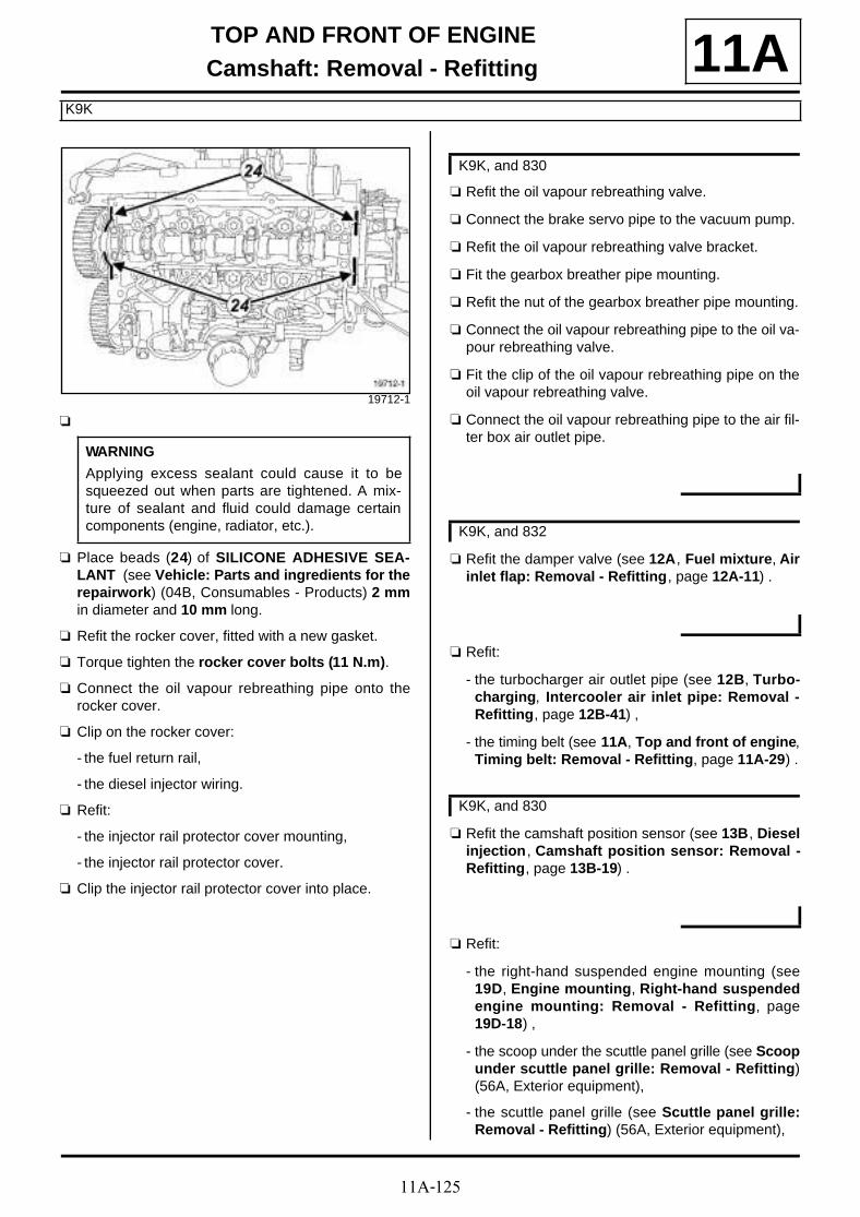
11A-125
TOP AND FRONT OF ENGINECamshaft: Removal - Refitting
K9K
11A
a
a Place beads (24) of SILICONE ADHESIVE SEA-LANT (see Vehicle: Parts and ingredients for therepairwork) (04B, Consumables - Products) 2 mmin diameter and 10 mm long.
a Refit the rocker cover, fitted with a new gasket.
a Torque tighten the rocker cover bolts (11 N.m).
a Connect the oil vapour rebreathing pipe onto therocker cover.
a Clip on the rocker cover:
- the fuel return rail,
- the diesel injector wiring.
a Refit:
- the injector rail protector cover mounting,
- the injector rail protector cover.
a Clip the injector rail protector cover into place.
a Refit the oil vapour rebreathing valve.
a Connect the brake servo pipe to the vacuum pump.
a Refit the oil vapour rebreathing valve bracket.
a Fit the gearbox breather pipe mounting.
a Refit the nut of the gearbox breather pipe mounting.
a Connect the oil vapour rebreathing pipe to the oil va-pour rebreathing valve.
a Fit the clip of the oil vapour rebreathing pipe on theoil vapour rebreathing valve.
a Connect the oil vapour rebreathing pipe to the air fil-ter box air outlet pipe.
a Refit the damper valve (see 12A, Fuel mixture, Airinlet flap: Removal - Refitting, page 12A-11) .
a Refit:
- the turbocharger air outlet pipe (see 12B, Turbo-charging, Intercooler air inlet pipe: Removal -Refitting, page 12B-41) ,
- the timing belt (see 11A, Top and front of engine,Timing belt: Removal - Refitting, page 11A-29) .
a Refit the camshaft position sensor (see 13B, Dieselinjection , Camshaft position sensor: Removal -Refitting, page 13B-19) .
a Refit:
- the right-hand suspended engine mounting (see19D, Engine mounting, Right-hand suspendedengine mounting: Removal - Refitting, page19D-18) ,
- the scoop under the scuttle panel grille (see Scoopunder scuttle panel grille: Removal - Refitting)(56A, Exterior equipment),
- the scuttle panel grille (see Scuttle panel grille:Removal - Refitting) (56A, Exterior equipment),
19712-1
WARNING
Applying excess sealant could cause it to besqueezed out when parts are tightened. A mix-ture of sealant and fluid could damage certaincomponents (engine, radiator, etc.).
K9K, and 830
K9K, and 832
K9K, and 830
11A-126
TOP AND FRONT OF ENGINECamshaft: Removal - Refitting
K9K
11A- the windscreen wiper arms (see Windscreen wi-per arm: Removal - Refitting) (85A, Wiping -Washing),
- the crankshaft accessories pulley (see 11A, Topand front of engine, Crankshaft accessoriespulley: Removal - Refitting, page 11A-15) ,
- the accessories belt (see 11A, Top and front ofengine, Accessories belt: Removal - Refitting,page 11A-7) ,
- the engine undertray,
- the front section of the front right-hand wheel archliner (see Front wheel arch liner: Removal - Re-fitting) (55A, Exterior protection),
- the front right-hand wheel (see Wheel: Removal -Refitting) (35A, Wheels and tyres),
- the engine cover.
a Connect the battery (see Battery : Removal - Refit-ting) (80A, Battery).
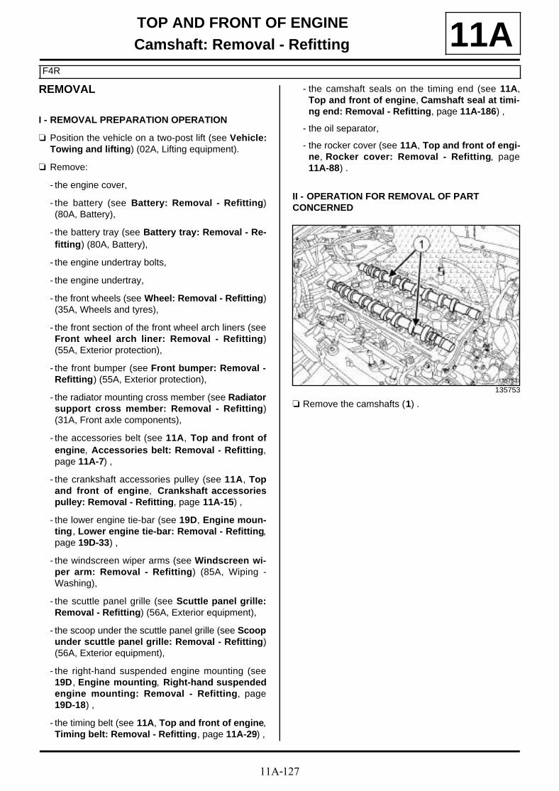
11A-127
TOP AND FRONT OF ENGINECamshaft: Removal - Refitting
F4R
11AREMOVAL
I - REMOVAL PREPARATION OPERATION
a Position the vehicle on a two-post lift (see Vehicle:Towing and lifting) (02A, Lifting equipment).
a Remove:
- the engine cover,
- the battery (see Battery: Removal - Refitting)(80A, Battery),
- the battery tray (see Battery tray: Removal - Re-fitting) (80A, Battery),
- the engine undertray bolts,
- the engine undertray,
- the front wheels (see Wheel: Removal - Refitting)(35A, Wheels and tyres),
- the front section of the front wheel arch liners (seeFront wheel arch liner: Removal - Refitting)(55A, Exterior protection),
- the front bumper (see Front bumper: Removal -Refitting) (55A, Exterior protection),
- the radiator mounting cross member (see Radiatorsupport cross member: Removal - Refitting)(31A, Front axle components),
- the accessories belt (see 11A, Top and front ofengine, Accessories belt: Removal - Refitting,page 11A-7) ,
- the crankshaft accessories pulley (see 11A, Topand front of engine, Crankshaft accessoriespulley: Removal - Refitting, page 11A-15) ,
- the lower engine tie-bar (see 19D, Engine moun-ting, Lower engine tie-bar: Removal - Refitting,page 19D-33) ,
- the windscreen wiper arms (see Windscreen wi-per arm: Removal - Refitting) (85A, Wiping -Washing),
- the scuttle panel grille (see Scuttle panel grille:Removal - Refitting) (56A, Exterior equipment),
- the scoop under the scuttle panel grille (see Scoopunder scuttle panel grille: Removal - Refitting)(56A, Exterior equipment),
- the right-hand suspended engine mounting (see19D, Engine mounting, Right-hand suspendedengine mounting: Removal - Refitting, page19D-18) ,
- the timing belt (see 11A, Top and front of engine,Timing belt: Removal - Refitting, page 11A-29) ,
- the camshaft seals on the timing end (see 11A,Top and front of engine, Camshaft seal at timi-ng end: Removal - Refitting, page 11A-186) ,
- the oil separator,
- the rocker cover (see 11A, Top and front of engi-ne, Rocker cover: Removal - Refitting, page11A-88) .
II - OPERATION FOR REMOVAL OF PART CONCERNED
a Remove the camshafts (1) .
135753

11A-128
TOP AND FRONT OF ENGINECamshaft: Removal - Refitting
F4R
11A
a Remove:
- the valve rockers (2) ,
- the hydraulic tappets (3) .
14499
Note:
To prevent any risk of unpriming the hydraulictappets make sure that they are vertical.
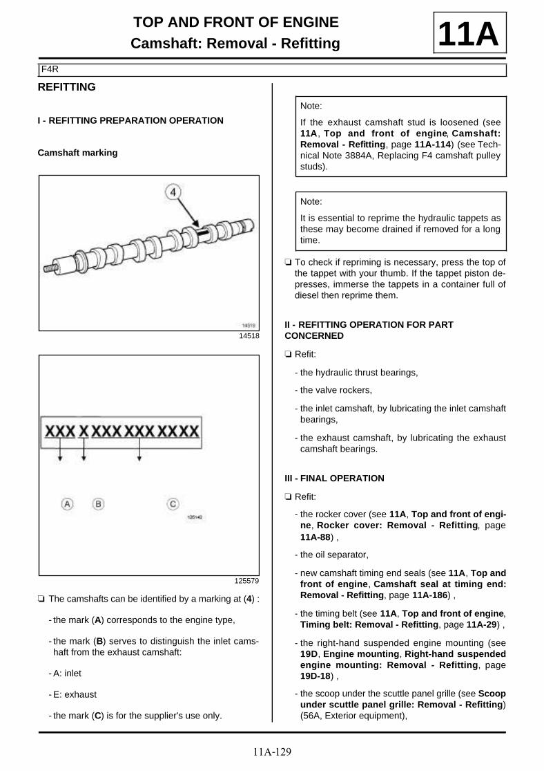
11A-129
TOP AND FRONT OF ENGINECamshaft: Removal - Refitting
F4R
11AREFITTING
I - REFITTING PREPARATION OPERATION
Camshaft marking
a The camshafts can be identified by a marking at (4) :
- the mark (A) corresponds to the engine type,
- the mark (B) serves to distinguish the inlet cams-haft from the exhaust camshaft:
- A: inlet
- E: exhaust
- the mark (C) is for the supplier's use only.
a To check if repriming is necessary, press the top ofthe tappet with your thumb. If the tappet piston de-presses, immerse the tappets in a container full ofdiesel then reprime them.
II - REFITTING OPERATION FOR PART CONCERNED
a Refit:
- the hydraulic thrust bearings,
- the valve rockers,
- the inlet camshaft, by lubricating the inlet camshaftbearings,
- the exhaust camshaft, by lubricating the exhaustcamshaft bearings.
III - FINAL OPERATION
a Refit:
- the rocker cover (see 11A, Top and front of engi-ne, Rocker cover: Removal - Refitting, page11A-88) ,
- the oil separator,
- new camshaft timing end seals (see 11A, Top andfront of engine, Camshaft seal at timing end:Removal - Refitting, page 11A-186) ,
- the timing belt (see 11A, Top and front of engine,Timing belt: Removal - Refitting, page 11A-29) ,
- the right-hand suspended engine mounting (see19D, Engine mounting, Right-hand suspendedengine mounting: Removal - Refitting, page19D-18) ,
- the scoop under the scuttle panel grille (see Scoopunder scuttle panel grille: Removal - Refitting)(56A, Exterior equipment),
14518
125579
Note:
If the exhaust camshaft stud is loosened (see11A, Top and front of engine, Camshaft:Removal - Refitting, page 11A-114) (see Tech-nical Note 3884A, Replacing F4 camshaft pulleystuds).
Note:
It is essential to reprime the hydraulic tappets asthese may become drained if removed for a longtime.

11A-130
TOP AND FRONT OF ENGINECamshaft: Removal - Refitting
F4R
11A- the scuttle panel grille (see Scuttle panel grille:Removal - Refitting) (56A, Exterior equipment),
- the windscreen wiper arms (see Windscreen wi-per arm: Removal - Refitting) (85A, Wiping -Washing),
- the lower engine tie-bar (see 19D, Engine moun-ting, Lower engine tie-bar: Removal - Refitting,page 19D-33) ,
- the crankshaft accessories pulley (see 11A, Topand front of engine, Crankshaft accessoriespulley: Removal - Refitting, page 11A-15) ,
- the accessories belt (see 11A, Top and front ofengine, Accessories belt: Removal - Refitting,page 11A-7) ,
- the radiator mounting cross member (see Radiatorsupport cross member: Removal - Refitting)(31A, Front axle components),
- the front bumper (see Front bumper: Removal -Refitting) (55A, Exterior protection),
- the front section of the front wheel arch liners (seeFront wheel arch liner: Removal - Refitting)(55A, Exterior protection),
- the front wheels (see Wheel: Removal - Refitting)(35A, Wheels and tyres),
- the engine undertray,
- the battery tray (see Battery tray: Removal - Re-fitting) (80A, Battery),
- the battery (see Battery: Removal - Refitting)(80A, Battery),
- the engine cover.
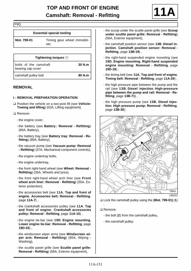
11A-131
TOP AND FRONT OF ENGINECamshaft: Removal - Refitting
F9Q
11A
REMOVAL
I - REMOVAL PREPARATION OPERATION
a Position the vehicle on a two-post lift (see Vehicle:Towing and lifting) (02A, Lifting equipment).
a Remove:
- the engine cover,
- the battery (see Battery : Removal - Refitting)(80A, Battery),
- the battery tray (see Battery tray: Removal - Re-fitting) (80A, Battery).
- the vacuum pump (see Vacuum pump: Removal- Refitting) (37A, Mechanical component controls),
- the engine undertray bolts,
- the engine undertray,
- the front right-hand wheel (see Wheel: Removal -Refitting) (35A, Wheels and tyres),
- the front right-hand wheel arch liner (see Frontwheel arch liner: Removal - Refitting) (55A, Ex-terior protection),
- the accessories belt (see 11A, Top and front ofengine, Accessories belt: Removal - Refitting,page 11A-7) ,
- the crankshaft accessories pulley (see 11A, Topand front of engine, Crankshaft accessoriespulley: Removal - Refitting, page 11A-15) ,
- the engine tie-bar (see 19D, Engine mounting,Lower engine tie-bar: Removal - Refitting, page19D-33) ,
- the windscreen wiper arms (see Windscreen wi-per arm: Removal - Refitting) (85A, Wiping -Washing),
- the scuttle panel grille (see Scuttle panel grille:Removal - Refitting) (56A, Exterior equipment),
- the scoop under the scuttle panel grille (see Scoopunder scuttle panel grille: Removal - Refitting)(56A, Exterior equipment),
- the camshaft position sensor (see 13B, Diesel in-jection, Camshaft position sensor: Removal -Refitting, page 13B-19) ,
- the right-hand suspended engine mounting (see19D, Engine mounting, Right-hand suspendedengine mounting: Removal - Refitting, page19D-18) ,
- the timing belt (see 11A, Top and front of engine,Timing belt: Removal - Refitting, page 11A-29) ,
- the high pressure pipe between the pump and therail (see 13B, Diesel injection, High-pressurepipe between the pump and rail: Removal - Re-fitting, page 13B-71) ,
- the high pressure pump (see 13B, Diesel injec-tion, High pressure pump: Removal - Refitting,page 13B-30) .
a Lock the camshaft pulley using the (Mot. 799-01) (1).
a Remove:
- the bolt (2) from the camshaft pulley,
- the camshaft pulley.
Essential special tooling
Mot. 799-01 Timing gear wheel immobili-ser.
Tightening torquesm
bolts of the camshaftbearing cap cover
30 N.m
camshaft pulley bolt 80 N.m
136222

11A-132
TOP AND FRONT OF ENGINECamshaft: Removal - Refitting
F9Q
11A
a Remove:
- the inner timing cover bolts (3) ,
- the inner timing cover,
- the rocker cover (see 11A, Top and front of engi-ne, Rocker cover: Removal - Refitting, page11A-88) .
II - OPERATION FOR REMOVAL OF PART CONCERNED
a Remove:
- the bolts of the camshaft bearing cap cover,
- the camshaft bearing cap cover,
a Remove:
- the camshaft (4) ,
- the camshaft seal on the timing end.
REFITTING
I - REFITTING PREPARATION OPERATION
a
a Use SUPER CLEANING AGENT FOR JOINT FA-CES (see Vehicle: Parts and ingredients for the repairwork) (04B, Consumables - Products) to clean:
- the joint face of the camshaft bearing cap cover,
- the cylinder head joint face.
a Use SURFACE CLEANER (see Vehicle: Parts and ingredients for the repairwork) (04B, Consu-mables - Products) to degrease:
- the joint face of the camshaft bearing cap cover,
136226
136227
136229
WARNING
Do not scrape the joint faces of the aluminium,any damage caused to the joint face will result ina risk of leaks.
WARNING
To ensure proper sealing, the gasket surfacesmust be clean, dry and not greasy (avoid any fin-ger marks).

11A-133
TOP AND FRONT OF ENGINECamshaft: Removal - Refitting
F9Q
11A- the cylinder head joint face.
a parts always to be replaced: Camshaft seal on ti-ming end (10,02,02,02).
parts always to be replaced: Camshaft timingsprocket bolt (10,02,02,16).
a
a Apply RESIN ADHESIVE (see Vehicle: Parts andingredients for the repairwork) (04B, Consuma-bles - Products) using a stipple roller on the jointface of the camshaft bearing cap cover until the jointface is completely coated.
a Use a cloth to remove any RESIN ADHESIVE in thecamshaft bearing caps.
II - REFITTING OPERATION FOR PART CONCERNED
a Refit the camshaft.
a Apply a drop of FRENETANCHE (see Vehicle:Parts and ingredients for the repairwork) (04B,Consumables - Products) on the bolts of the cams-haft bearing cap cover.
a Refit the camshaft bearing cap cover.
a Torque tighten the bolts of the camshaft bearingcap cover (30 N.m).
III - FINAL OPERATION
a Refit:
- the rocker cover (see 11A, Top and front of engi-ne, Rocker cover: Removal - Refitting, page11A-88) ,
- a new camshaft seal on the timing end (see 11A,Top and front of engine, Camshaft seal at timi-ng end: Removal - Refitting, page 11A-186) ,
- the inner timing cover,
- the camshaft pulley.
a Lock the camshaft pulley using the (Mot. 799-01).
a Torque tighten the camshaft pulley bolt (80 N.m).
a Refit:
- the high pressure pump (see 13B, Diesel injec-tion, High pressure pump: Removal - Refitting,page 13B-30) ,
- the high pressure pipe between the pump and therail (see 13B, Diesel injection, High-pressurepipe between the pump and rail: Removal - Re-fitting, page 13B-71) ,
- the timing belt (see 11A, Top and front of engine,Timing belt: Removal - Refitting, page 11A-29) ,
- the right-hand suspended engine mounting (see19D, Engine mounting, Right-hand suspendedengine mounting: Removal - Refitting, page19D-18) ,
- the camshaft position sensor (see 13B, Diesel in-jection, Camshaft position sensor: Removal -Refitting, page 13B-19) ,
- the scoop under the scuttle panel grille (see Scoopunder scuttle panel grille: Removal - Refitting)(56A, Exterior equipment),
- the scuttle panel grille (see Scuttle panel grille:Removal - Refitting) (56A, Exterior equipment),
- the windscreen wiper arms (see Windscreen wi-per arm: Removal - Refitting) (85A, Wiping -Washing),
- the engine tie-bar (see 19D, Engine mounting,Lower engine tie-bar: Removal - Refitting, page19D-33) ,
- the crankshaft accessories pulley (see 11A, Topand front of engine, Crankshaft accessoriespulley: Removal - Refitting, page 11A-15) ,
- the accessories belt (see 11A, Top and front ofengine, Accessories belt: Removal - Refitting,page 11A-7) ,
12515
WARNING
Applying excess sealant could cause it to besqueezed out when parts are tightened. A mix-ture of sealant and fluid could damage certaincomponents (engine, radiator, etc.).

11A-134
TOP AND FRONT OF ENGINECamshaft: Removal - Refitting
F9Q
11A- the front right-hand wheel arch liner (see Frontwheel arch liner: Removal - Refitting) (55A, Ex-terior protection),
- the front right-hand wheel (see Wheel: Removal -Refitting) (35A, Wheels and tyres),
- the engine undertray,
- the vacuum pump (see Vacuum pump: Removal- Refitting) (37A, Mechanical component controls),
- the battery tray (see Battery tray: Removal - Re-fitting) (80A, Battery),
- the battery (see Battery : Removal - Refitting)(80A, Battery),
- the engine cover.

11A-135
TOP AND FRONT OF ENGINECylinder head: Removal - Refitting
K9K
11A
REMOVAL
I - REMOVAL PREPARATION OPERATION
a Position the vehicle on a two-post lift (see Vehicle:Towing and lifting) (02A, Lifting equipment).
a Disconnect the battery (see Battery : Removal -Refitting) (80A, Battery).
a Remove:
- the engine cover,
- the front wheels (see Wheel: Removal - Refitting)(35A, Wheels and tyres),
- the front section of the front wheel arch liners (seeFront wheel arch liner: Removal - Refitting)(55A, Exterior protection),
- the engine undertray bolts,
- the engine undertray,
- the front bumper (see Front bumper: Removal -Refitting) (55A, Exterior protection),
- the catalytic converter (see 19B, Exhaust, Cataly-tic converter: Removal - Refitting, page 19B-17),
- the turbocharger oil return pipe (see 12B, Turbo-charging, Turbocharger oil pipe: Removal - Re-fitting, page 12B-22) ,
- the accessories belt (see 11A, Top and front ofengine, Accessories belt: Removal - Refitting,page 11A-7) ,
- the crankshaft accessories pulley (see 11A, Topand front of engine, Crankshaft accessoriespulley: Removal - Refitting, page 11A-15) ,
Essential special tooling
Mot. 1448 Long nose pliers for hoseclips.
Mot. 1390 Support for removing/refittingthe engine - gearbox assem-bly.
Mot. 1453 Multiple-adjusting enginemounting support with retai-ning straps.
Mot. 1453-01 Additional winder nut onengine lift support Mot. 1453.
Essential equipment
safety strap(s)
cylinder head rule
set of feeler gauges
Tightening torquesm
new cylinder head bolts(initial torque)
20 Nm
new cylinder head bolts 25 N.m
new cylinder head bolts 270˚ ±±±± 10˚
alternator lower bolt 25 N.m
alternator upper bolt 25 N.m
air filter unit air outletpipe clip on the turbo-charger
5.5 N.m
rocker cover bolts 11 N.m
IMPORTANT
To avoid all risk of damage to the systems, applythe safety and cleanliness instructions and opera-tion recommendations before carrying out anyrepair (see 13B, Diesel injection, Diesel injec-tion: Precautions for repair, page 13B-1) .
IMPORTANT
Wear leaktight gloves (Nitrile type) for this opera-tion.
IMPORTANT
Use the diagnostic tool before any operation is car-ried out on the injection circuit to check:
- that the rail is not under pressure,
- that the fuel temperature is not too high.
Working on the circuit with the engine running isstrictly forbidden.
WARNING
To prevent impurities from entering the circuit, placeprotective plugs on all fuel circuit componentsexposed to the open air.
11A-136
TOP AND FRONT OF ENGINECylinder head: Removal - Refitting
K9K
11A- the windscreen wiper arms (see Windscreen wi-per arm: Removal - Refitting) (85A, Wiping -Washing),
- the scuttle panel grille (see Scuttle panel grille:Removal - Refitting) (56A, Exterior equipment),
- the scoop under the scuttle panel grille (see Scoopunder scuttle panel grille: Removal - Refitting)(56A, Exterior equipment),
- the right-hand suspended engine mounting (see19D, Engine mounting, Right-hand suspendedengine mounting: Removal - Refitting, page19D-18) .
a Remove the camshaft position sensor (see 13B,Diesel injection, Camshaft position sensor: Re-moval - Refitting, page 13B-19) .
a Remove:
- the timing belt (see 11A, Top and front of engine,Timing belt: Removal - Refitting, page 11A-29) ,
- the turbocharger air outlet pipe (see 12B, Turbo-charging, Intercooler air inlet pipe: Removal -Refitting, page 12B-41) ,
- the intercooler air outlet pipe (see 12B, Turbo-charging, Intercooler air outlet pipe: Removal -Refitting, page 12B-56) .
a Remove the damper valve (see 12A, Fuel mixture,Air inlet flap: Removal - Refitting, page 12A-11) .
K9K, and 830
K9K, and 832

11A-137
TOP AND FRONT OF ENGINECylinder head: Removal - Refitting
K9K
11A
a Disconnect the oil vapour rebreathing pipe unionfrom the air filter unit air outlet pipe at (1) .
a Separate the oil vapour rebreathing pipe clip (2)from the oil vapour rebreathing valve.
a Disconnect the oil vapour rebreathing pipe from theoil vapour rebreathing valve.
a Remove the nut (3) from the gearbox breather pipesupport.
a Separate the gearbox breather pipe support.
a Remove:
- the bracket bolts (4) of the oil vapour rebreathing
K9K, and 830
135880
135879
135845
112325

11A-138
TOP AND FRONT OF ENGINECylinder head: Removal - Refitting
K9K
11Avalve,
- the bracket of the oil vapour rebreathing valve.
a Disconnect the brake servo pipe union from the va-cuum pump.
a Remove:
- the nuts (5) of the oil vapour rebreathing valve,
- the oil vapour rebreathing valve,
- the seal of the oil vapour rebreathing valve.
a Unclip the injector rail protector cover at (6) .
a Remove:
- the injector rail protector cover bolt (7) ,
- the injector rail protector cover nut (8) ,
- the injector rail protector cover.
a Unclip the injector rail protector cover at (9) .
a Remove:
- the injector rail protector cover bolt (10) ,
- the injector rail protector cover.
K9K, and 832
134699
K9K, and 830
135878

11A-139
TOP AND FRONT OF ENGINECylinder head: Removal - Refitting
K9K
11A
a Remove:
- the bolts (11) of the injector rail protector coversupport,
- the injector rail protector cover support.
a Unclip the diesel injector wiring from the rocker co-ver at (12) .
a Unclip the diesel injector fuel return rail from the roc-ker cover at (13) .
a Remove the fuel return rail (see 13B, Diesel injec-tion, Diesel injector fuel return rail: Removal -Refitting, page 13B-63) .
a Disconnect the oil vapour rebreathing pipe from therocker cover.
134702
K9K, and 832
134701
K9K, and 832
134700
K9K, and 830
K9K, and 832

11A-140
TOP AND FRONT OF ENGINECylinder head: Removal - Refitting
K9K
11A
a Remove:
- the rocker cover bolts (14) ,
- the rocker cover.
a Remove:
- the rocker cover bolts (15) ,
- the rocker cover.
a Remove:
- the dipstick,
- the dipstick guide bolts (16) .
a Move aside the dipstick guide.
a Disconnect the vacuum pipe (17) of the turbochar-ging pressure regulation solenoid valve from the va-cuum pump.
a Unclip the hose of the turbocharging pressure regu-lator solenoid valve from the cylinder head.
K9K, and 832
135489
K9K, and 830
135876
134703
134704
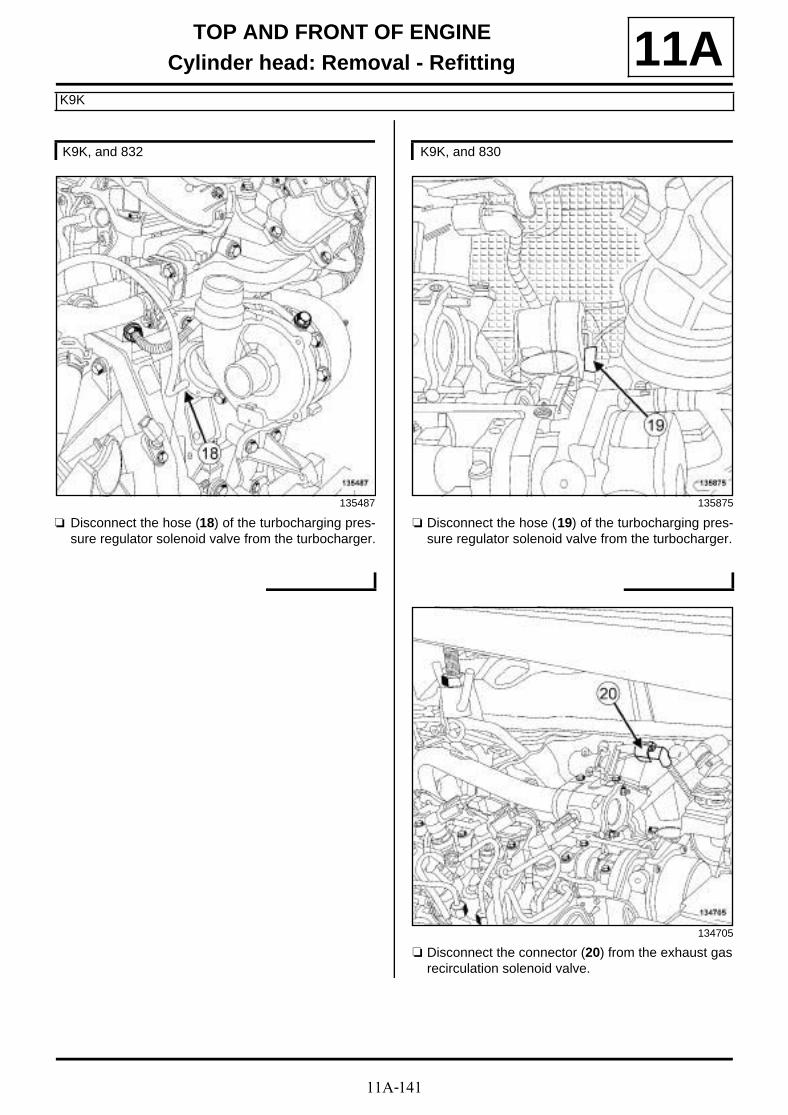
11A-141
TOP AND FRONT OF ENGINECylinder head: Removal - Refitting
K9K
11A
a Disconnect the hose (18) of the turbocharging pres-sure regulator solenoid valve from the turbocharger.
a Disconnect the hose (19) of the turbocharging pres-sure regulator solenoid valve from the turbocharger.
a Disconnect the connector (20) from the exhaust gasrecirculation solenoid valve.
K9K, and 832
135487
K9K, and 830
135875
134705

11A-142
TOP AND FRONT OF ENGINECylinder head: Removal - Refitting
K9K
11A
a Undo the air filter unit air outlet pipe clip (21) fromthe turbocharger.
a Undo the air filter unit air outlet pipe clip (22) fromthe turbocharger.
a Disconnect the air filter unit air outlet pipe from theturbocharger.
a Drain the cooling system (see 19A, Cooling, Coo-ling circuit: Draining - Refilling, page 19A-17) .
K9K, and 832
135410
K9K, and 830
136639

11A-143
TOP AND FRONT OF ENGINECylinder head: Removal - Refitting
K9K
11A
a Unclip the heater matrix cooling hose from the waterchamber (23) .
a Separate the heater matrix cooling hose clip (24)from the exhaust cooler cover using the tool (Mot.1448).
a Disconnect the heater matrix cooling hose from theexhaust gas cooler cover (25) .
a Use the tool (Mot. 1448) to separate the clip (26) ofthe cooling radiator top hose (27) from the waterchamber.
a Disconnect the cooling radiator top cooling hosefrom the water chamber (27) .
a Separate the heater matrix cooling hose clip (28)from the water chamber cooling hose using the tool(Mot. 1448).
a Disconnect the heater matrix cooling hose from thewater chamber cooling hose (29) .
a Disconnect the coolant temperature sensor connec-tor.
135484
135485
135485

11A-144
TOP AND FRONT OF ENGINECylinder head: Removal - Refitting
K9K
11A
a Unclip:
- the expansion bottle bottom cooling hose from thehigh pressure pump protector (30) ,
- the alternator wiring from the injector rail protectorat (31) .
a Disconnect:
- the connector (32) from the injector rail pressuresensor,
- the fuel temperature sensor connector (33) ,
- the connector (34) from the fuel pressure regula-tion solenoid valve,
- the connector (35) from the fuel flow regulation so-lenoid valve,
- all heater plug connectors,
- the connector for each diesel injector.
a Unclip the injection wiring clip (36) .
a Disconnect:
- the connector (37) from the injector rail pressuresensor,
- the fuel temperature sensor connector (38) ,
- the connector (39) from the fuel flow regulation so-lenoid valve,
- all heater plug connectors,
- the connector for each diesel injector.
a Unclip the clips (40) of the injection wiring.
a Separate the injection wiring.
K9K, and 832
134706
134706
K9K, and 830
135874
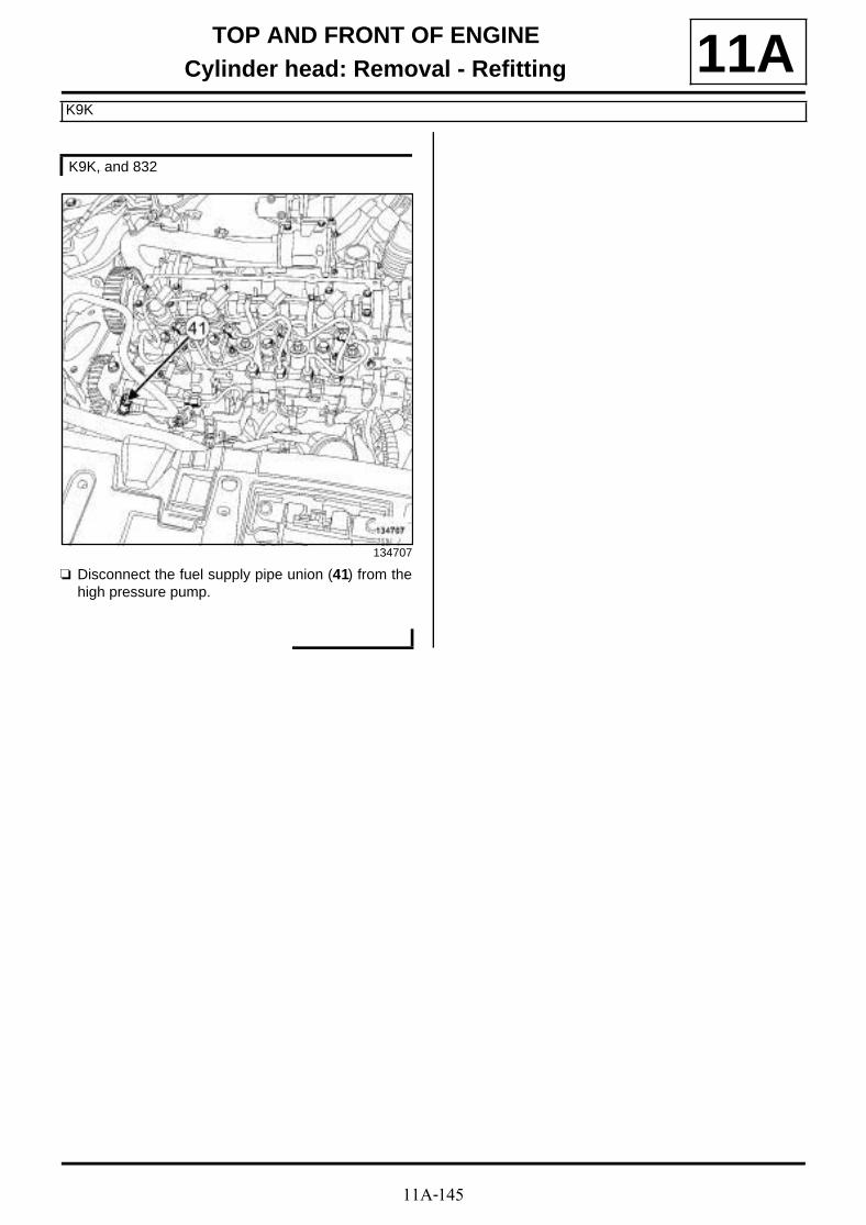
11A-145
TOP AND FRONT OF ENGINECylinder head: Removal - Refitting
K9K
11A
a Disconnect the fuel supply pipe union (41) from thehigh pressure pump.
K9K, and 832
134707

11A-146
TOP AND FRONT OF ENGINECylinder head: Removal - Refitting
K9K
11A
a Unclip the high pressure pump fuel return union fromthe high pressure pump protector at (42) .
a Remove:
- the bolt (43) of the high pressure pump protector,
- the high pressure pump protector.
a Disconnect the fuel supply pipe (44) from the highpressure pump.
a Fit a suitable blanking plug on:
- the fuel supply pipe union opening,
- the high pressure pump opening.
a Disconnect the fuel drain pipe from the injector railprotector (45) .
K9K, and 830
135873
135872
K9K, and 832
135468

11A-147
TOP AND FRONT OF ENGINECylinder head: Removal - Refitting
K9K
11A
a Remove the alternator upper bolt (46) .
a Loosen the alternator lower bolt (47) .
a Tilt the alternator slightly towards the front of the ve-hicle.
a Remove:
- the bolts (48) of the inner cover,
- the inner cover.
a Remove the alternator upper bolt (49) .
a Loosen the alternator lower bolt (50) .
a Tilt the alternator slightly towards the front of the ve-hicle.
a Remove:
- the bolts (51) of the inner cover,
- the inner cover.
a Fit the tool (Mot. 1390) under the vehicle.
a Remove:
- the safety strap(s),
- the (Mot. 1453) fitted with the (Mot. 1453-01).
II - OPERATION FOR REMOVAL OF PART CONCERNED
a
K9K, and 832
123969
K9K, and 830
136665
Note:
The operation to remove the cylinder head requi-res two people.

11A-148
TOP AND FRONT OF ENGINECylinder head: Removal - Refitting
K9K
11A
a
a Remove:
- the cylinder head bolts (52) ,
- the cylinder head from the cylinder block,
- the cylinder head gasket.
REFITTING
I - REFITTING PREPARATION OPERATION
a
a parts always to be replaced: Cylinder head bolts(10,02,01,14).
a parts always to be replaced: Cylinder head gas-ket (10,02,01,04).
a parts always to be replaced: Rocker cover gas-ket (10,02,01,12).
a Always replace the seal of the oil vapour rebreathingvalve.
K9K, and 832
Note:
Turn the camshaft slightly to facilitate the removalof the cylinder head bolt on the camshaft positionsensor target.
19712
IMPORTANT
Wear goggles with side protectors for this opera-tion.
IMPORTANT
Wear leaktight gloves (Nitrile type) for this opera-tion.
WARNING
Do not scrape the joint faces of the aluminium,any damage caused to the joint face will result ina risk of leaks.
WARNING
Do not allow this product to drip onto the pain-twork.
Clean the cylinder head carefully to avoid anyforeign bodies entering the oil return and supplypipes.
Failure to follow this advice could lead to theblocking of the various oil inlet galleries, whichwould quickly result in engine damage.
WARNING
To ensure proper sealing, the gasket surfacesmust be clean, dry and not greasy (avoid any fin-ger marks).
K9K, and 830

11A-149
TOP AND FRONT OF ENGINECylinder head: Removal - Refitting
K9K
11A1 - Cleaning the cylinder head joint face
a
a Clean the joint face using ABRASIVE PADS :
- of the cylinder head,
- of the cylinder block.
a Use a SURFACE CLEANER (see Vehicle: Parts and ingredients for the repairwork) (04B, Consu-mables - Products) and CLEAN CLOTHS to de-grease the joint faces:
- of the cylinder head,
- of the cylinder block,
- of the exhaust gas cooler mounting on the gearboxside,
- of the oil vapour rebreathing valve.
2 - Checking the gasket face
a Check with a cylinder head rule and a set of feelergauges to determine if the joint face has been defor-med.
a The maximum deformation is 0.05 mm.
3 - Cleaning the joint face of the rocker cover
a
a Clean the cylinder head joint face using ABRASIVEPADS.
a Use SURFACE CLEANER (see Vehicle: Parts and ingredients for the repairwork) (04B, Consu-mables - Products) and CLEAN CLOTHS to de-grease:
- the cylinder head joint face,
- the rocker cover housing.
II - REFITTING OPERATION FOR PART CONCERNED
a Bring the pistons to mid-stroke position to preventany risk of contact with the valves when tighteningthe cylinder head.
WARNING
Protect the oilway so that foreign bodies do notenter the oil pipes in the cylinder head.
Failure to follow this instruction could lead to theblocking of the oilways, resulting in a rapid dete-rioration of the camshaft.
WARNING
No regrinding of the cylinder head is permitted.
Note:
If the cylinder head is faulty:
-strip down the cylinder head (see Stripping thecylinder head) (Technical Note 6006A, 10A,Engine and cylinder block assembly),
-test the cylinder head for possible cracks usingthe cylinder head test kit,
-rebuild the cylinder head (see Stripping thecylinder head) (Technical Note 6006A, 10A,Engine and cylinder block assembly).
WARNING
Do not scrape the joint faces of the aluminium,any damage caused to the joint face will result ina risk of leaks.
WARNINGTo ensure proper sealing, the gasket surfacesmust be clean, dry and not greasy (avoid any fin-ger marks).
Note:
The operation to refit the cylinder head requirestwo people.
Note:
The cylinder head gasket has a foolproofingdevice which must be positioned on the cylinderblock inlet side.

11A-150
TOP AND FRONT OF ENGINECylinder head: Removal - Refitting
K9K
11Aa Fit:
- a new cylinder head gasket, centred by twodowels,
- the cylinder head on the cylinder block.
a Refit in order the new cylinder head bolts.
a Pretighten to torque and in order the new cylinderhead bolts (initial torque) (20 Nm).
a Tighten to torque and in order the new cylinderhead bolts (25 N.m).
a Check that all of the new cylinder head mountingbolts are tightened to the correct torque (25 N.m).
a Angle tighten in order the new cylinder head bolts(270˚ ±±±± 10 )̊.
III - FINAL OPERATION
a Fit the (Mot. 1453) fitted with the (Mot. 1453-01).
a Remove the tool (Mot. 1390).
a Refit the inner cover.
a Fit the alternator in place.
a Refit the alternator upper bolt.
a Tighten to torque:
- the alternator lower bolt (25 N.m),
- the alternator upper bolt (25 N.m).
a Connect the fuel drain pipe on the injector rail pro-tector.
a Remove the blanking plug
- on the high pressure pump opening,
- on the fuel supply pipe union opening.
a Connect the fuel supply pipe to the high pressurepump.
a Refit the high pressure pump protector.
a Clip the high pressure pump fuel return union ontothe high pressure pump protector.
a Fit the injection wiring.
a Clip on the injection wiring clip.
a Connect:
- the connector for each diesel injector,
- all heater plug connectors,
- the fuel flow regulation solenoid valve connector,
- the fuel pressure regulation solenoid valve connec-tor,
- the fuel temperature sensor connector,
- the injector rail pressure sensor connector.
a Clip:
- the alternator wiring onto the injector rail protector,
- the expansion bottle bottom cooling hose onto thehigh pressure pump protector.
a Clip on the injection wiring clips.
a Connect:
- the connector for each diesel injector,
WARNING
In order to ensure that the bolts are correctlytightened, use a syringe to remove any oil whichmay be in the cylinder head mounting holes.
WARNING
Do not oil the new bolts. Be sure to oil boltsbeing reused.
19712
K9K, and 832
K9K, and 830
K9K, and 832
K9K, and 830

11A-151
TOP AND FRONT OF ENGINECylinder head: Removal - Refitting
K9K
11A- all heater plug connectors,
- the fuel flow regulation solenoid valve connector,
- the fuel temperature sensor connector,
- the injector rail pressure sensor connector.
a Connect:
- the coolant temperature sensor connector,
- the heater matrix cooling hose to the water cham-ber cooling hose.
a Fit the heater matrix cooling hose clip onto the waterchamber cooling hose using the tool (Mot. 1448).
a Connect the cooling radiator top cooling hose to thewater chamber.
a Fit the cooling radiator top cooling hose clip to thewater chamber.
a Connect the heater matrix cooling hose to the ex-haust gas cooler cover.
a Fit the heater matrix cooling hose clip on the exhaustgas cooler cover using the tool (Mot. 1448).
a Clip the heater matrix cooling hose onto the waterchamber.
a Fill and bleed the cooling system (see 19A, Coo-ling, Cooling circuit: Draining - Refilling, page19A-17) .
a Connect the air filter unit air outlet pipe to the turbo-charger.
a Torque tighten the air filter unit air outlet pipe clipon the turbocharger (5.5 N.m).
a Connect:
- exhaust gas recirculation solenoid valve connector,
- the turbocharging pressure regulation solenoid val-ve hose.
a Clip on the turbocharging pressure regulation sole-noid valve hose.
a Connect the turbocharging pressure regulation sole-noid valve hose to the vacuum pump.
a Fit the dipstick guide.
a Refit:
- the dipstick guide bolts,
- the dipstick.
a
a Place beads (53) of SILICONE ADHESIVE SEA-LANT (see Vehicle: Parts and ingredients for therepairwork) (04B, Consumables - Products) 2 mmin diameter and 10 mm long.
a Refit the rocker cover, fitted with a new gasket.
a Torque tighten the rocker cover bolts (11 N.m).
a Connect the oil vapour rebreathing pipe onto therocker cover.
a Refit the diesel injector fuel return rail (see 13B, Die-sel injection, Diesel injector fuel return rail: Re-moval - Refitting, page 13B-63) .
a Clip on the rocker cover:
- the diesel injector fuel return rail,
- the diesel injector wiring.
19712-1
WARNING
Applying excess sealant could cause it to besqueezed out when parts are tightened. A mix-ture of sealant and fluid could damage certaincomponents (engine, radiator, etc.).
K9K, and 832
K9K, and 830
K9K, and 832

11A-152
TOP AND FRONT OF ENGINECylinder head: Removal - Refitting
K9K
11Aa Refit:
- the support of the injector rail protector cover,
- the injector rail protector cover.
a Clip on the injector rail protector cover.
a Refit:
- the oil vapour rebreathing valve seal on oil vapourrebreathing valve,
- the oil vapour rebreathing valve.
a Connect the brake servo pipe union to the vacuumpump.
a Refit the bracket of the oil vapour rebreathing valve.
a Fit the breather support onto the gearbox.
a Refit the breather support nut on the gearbox.
a Connect the oil vapour rebreathing pipe on the oilvapour rebreathing valve.
a Fit the oil vapour rebreathing pipe clip on the oil va-pour rebreathing valve.
a Connect the oil vapour rebreathing pipe union to theair filter unit air outlet pipe.
a Refit the damper valve (see 12A, Fuel mixture, Airinlet flap: Removal - Refitting, page 12A-11) .
a Refit:
- the intercooler air outlet pipe (see 12B, Turbo-charging, Intercooler air outlet pipe: Removal -Refitting, page 12B-56) ,
- the turbocharger air outlet pipe (see 12B, Turbo-charging, Intercooler air inlet pipe: Removal -Refitting, page 12B-41) ,
- the timing belt (see 11A, Top and front of engine,Timing belt: Removal - Refitting, page 11A-29) .
a Refit the camshaft position sensor (see 13B, Dieselinjection , Camshaft position sensor: Removal -Refitting, page 13B-19) .
a Refit:
- the right-hand suspended engine mounting (see19D, Engine mounting, Right-hand suspendedengine mounting: Removal - Refitting, page19D-18) ,
- the scoop under the scuttle panel grille (see Scoopunder scuttle panel grille: Removal - Refitting)(56A, Exterior equipment),
- the scuttle panel grille (see Scuttle panel grille:Removal - Refitting) (56A, Exterior equipment),
- the windscreen wiper arms (see Windscreen wi-per arm: Removal - Refitting) (85A, Wiping -Washing),
- the accessories belt (see 11A, Top and front ofengine, Accessories belt: Removal - Refitting,page 11A-7) ,
- the turbocharger oil return pipe (see 12B, Turbo-charging, Turbocharger oil pipe: Removal - Re-fitting, page 12B-22) ,
- the catalytic converter (see 19B, Exhaust, Cataly-tic converter: Removal - Refitting, page 19B-17),
- the front bumper (see Front bumper: Removal -Refitting) (55A, Exterior protection),
- the engine undertray,
- the front section of the front wheel arch liners (seeFront wheel arch liner: Removal - Refitting)(55A, Exterior protection),
- the front wheels (see Wheel: Removal - Refitting)(35A, Wheels and tyres),
- the engine cover.
a Connect the battery (see Battery : Removal - Refit-ting) (80A, Battery).
K9K, and 830
K9K, and 832
K9K, and 830
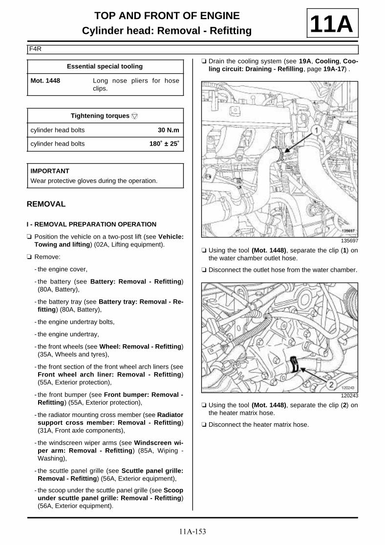
11A-153
TOP AND FRONT OF ENGINECylinder head: Removal - Refitting
F4R
11A
REMOVAL
I - REMOVAL PREPARATION OPERATION
a Position the vehicle on a two-post lift (see Vehicle:Towing and lifting) (02A, Lifting equipment).
a Remove:
- the engine cover,
- the battery (see Battery: Removal - Refitting)(80A, Battery),
- the battery tray (see Battery tray: Removal - Re-fitting) (80A, Battery),
- the engine undertray bolts,
- the engine undertray,
- the front wheels (see Wheel: Removal - Refitting)(35A, Wheels and tyres),
- the front section of the front wheel arch liners (seeFront wheel arch liner: Removal - Refitting)(55A, Exterior protection),
- the front bumper (see Front bumper: Removal -Refitting) (55A, Exterior protection),
- the radiator mounting cross member (see Radiatorsupport cross member: Removal - Refitting)(31A, Front axle components),
- the windscreen wiper arms (see Windscreen wi-per arm: Removal - Refitting) (85A, Wiping -Washing),
- the scuttle panel grille (see Scuttle panel grille:Removal - Refitting) (56A, Exterior equipment),
- the scoop under the scuttle panel grille (see Scoopunder scuttle panel grille: Removal - Refitting)(56A, Exterior equipment).
a Drain the cooling system (see 19A, Cooling, Coo-ling circuit: Draining - Refilling, page 19A-17) .
a Using the tool (Mot. 1448), separate the clip (1) onthe water chamber outlet hose.
a Disconnect the outlet hose from the water chamber.
a Using the tool (Mot. 1448), separate the clip (2) onthe heater matrix hose.
a Disconnect the heater matrix hose.
Essential special tooling
Mot. 1448 Long nose pliers for hoseclips.
Tightening torquesm
cylinder head bolts 30 N.m
cylinder head bolts 180˚ ±±±± 25˚
IMPORTANT
Wear protective gloves during the operation.
135697
120243

11A-154
TOP AND FRONT OF ENGINECylinder head: Removal - Refitting
F4R
11A
a Disconnect the coolant temperature sensor connec-tor (3) from the water chamber.
a Disconnect:
- the air temperature sensor connector (4) on the in-tercooler air outlet pipe,
- the air pressure sensor connector (5) on the inter-cooler air outlet pipe.
a Disconnect the injector connectors (6) .
a Disconnect:
- the oil vapour rebreathing solenoid valve connector(7) ,
- the air pressure sensor connector (8) on the inletmanifold.
120242
135793
134642
135777
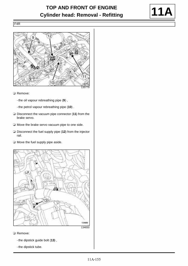
11A-155
TOP AND FRONT OF ENGINECylinder head: Removal - Refitting
F4R
11A
a Remove:
- the oil vapour rebreathing pipe (9) ,
- the petrol vapour rebreathing pipe (10) .
a Disconnect the vacuum pipe connector (11) from thebrake servo.
a Move the brake servo vacuum pipe to one side.
a Disconnect the fuel supply pipe (12) from the injectorrail.
a Move the fuel supply pipe aside.
a Remove:
- the dipstick guide bolt (13) ,
- the dipstick tube.
135779
134650

11A-156
TOP AND FRONT OF ENGINECylinder head: Removal - Refitting
F4R
11A
a Remove:
- the bolt (14) from the intercooler air outlet pipe onthe inlet manifold,
- the bolts (15) from the intercooler air outlet pipe onthe throttle valve.
a Move the intercooler air outlet pipe to one side.
a Remove:
- the camshaft position sensor (see 17B, Petrol in-jection, Camshaft position sensor: Removal -Refitting, page 17B-13) ,
- the camshaft dephaser solenoid valve (see 11A,
Top and front of engine, Camshaft dephasersolenoid valve: Removal - Refitting, page 11A-184) ,
- the ignition coils (see 17A, Ignition, Coils Remo-val - Refitting, page 17A-1) ,
- the spark plugs (see 17A, Ignition, Spark plugs:Removal - Refitting, page 17A-5) .
a Move aside the engine wiring.
a Remove:
- the bolt (16) from the air conditioning pipe on the in-let manifold,
- the accessories belt (see 11A, Top and front ofengine, Accessories belt: Removal - Refitting,page 11A-7) ,
- the crankshaft accessories pulley (see 11A, Topand front of engine, Crankshaft accessoriespulley: Removal - Refitting, page 11A-15) ,
- the right-hand suspended engine mounting (see19D, Engine mounting, Right-hand suspendedengine mounting: Removal - Refitting, page19D-18) ,
- the timing belt (see 11A, Top and front of engine,Timing belt: Removal - Refitting, page 11A-29) ,
- the lower engine tie-bar (see 19D, Engine moun-ting, Lower engine tie-bar: Removal - Refitting,page 19D-33) .
a Drain the manual gearbox (see Manual gearboxoil: Draining - Refilling) (21A, Manual gearbox).
135746
135796
135700

11A-157
TOP AND FRONT OF ENGINECylinder head: Removal - Refitting
F4R
11Aa Remove:
- the front right-hand wheel driveshaft (see Front ri-ght-hand wheel driveshaft: Removal - Refitting)(29A, Driveshafts),
- the right-hand differential output seal (see Front ri-ght-hand wheel driveshaft: Removal - Refitting)(21A, Manual gearbox),
- the catalytic converter (see 19B, Exhaust, Cataly-tic converter: Removal - Refitting, page 19B-17),
- the turbocharger (see 12B, Turbocharging, Tur-bocharger: Removal - Refitting, page 12B-8) ,
- the oil separator (see 11A, Top and front of engi-ne, Oil decanter: Removal - Refitting, page 11A-205) ,
- the rocker cover (see 11A, Top and front of engi-ne, Rocker cover: Removal - Refitting, page11A-88) ,
- the camshafts (see 11A, Top and front of engine,Camshaft: Removal - Refitting, page 11A-114) ,
- the timing end camshaft seals (see 11A, Top andfront of engine, Camshaft seal at timing end:Removal - Refitting, page 11A-186) .
a
a Remove:
- the valve rockers (17) ,
- the hydraulic tappets (18) .
II - OPERATION FOR REMOVAL OF PART CONCERNED
a Remove:
- the cylinder head bolts,
- the cylinder head,
- the cylinder head gasket.
REFITTING
I - REFITTING PREPARATION OPERATION
a parts always to be replaced: Cylinder head gas-ket (10,02,01,04).
a parts always to be replaced: Cylinder head bolts(10,02,01,14).
14499
Note:
To prevent any risk of unpriming the hydraulictappets, make sure that they are vertical.
121293
11A-158
TOP AND FRONT OF ENGINECylinder head: Removal - Refitting
F4R
11A1 - Cleaning the cylinder head joint face
a
a Clean the joint faces with SUPER CLEANING AGENT FOR JOINT FACES (see Vehicle: Parts and ingredients for the repairwork) (04B, Consu-mables - Products):
- the cylinder head gasket face if being reused,
- the cylinder block gasket face.
a Use SURFACE CLEANER (see Vehicle: Parts and ingredients for the repairwork) (04B, Consu-mables - Products) to degrease:
- the cylinder head gasket face if being reused,
- the cylinder block gasket face.
2 - Checking the gasket face
a Check for gasket face deformation using a ruler anda set of shims.
a The maximum deformation is 0.05 mm.
II - OPERATION FOR REFITTING PART CONCERNED
a Bring the pistons to mid-stroke position to preventany risk of contact with the valves when tighteningthe cylinder head.
IMPORTANT
Wear goggles with side protectors for this opera-tion.
IMPORTANTWear leaktight gloves (Nitrile type) for this opera-tion.
WARNING
Do not scrape the joint faces of the aluminium,any damage caused to the joint face will result ina risk of leaks.
WARNING
Do not allow this product to drip onto the pain-twork.
Clean the cylinder head carefully to avoid anyforeign bodies entering the oil return and supplypipes.
Failure to follow this advice could lead to theblocking of the various oil inlet galleries, whichwould quickly result in engine damage.
WARNING
To ensure proper sealing, the gasket surfacesmust be clean, dry and not greasy (avoid any fin-ger marks).
WARNING
Protect the oilway so that foreign bodies do notenter the oil pipes in the cylinder head.
Failure to follow this instruction could lead to theblocking of the oilways, resulting in a rapid dete-rioration of the camshaft.
WARNING
No regrinding of the cylinder head is permitted.
Note:
If the cylinder head is faulty:
-strip the cylinder head (see Stripping the cylin-der head) (Technical Note 6027A, 10A, Engineand cylinder block assembly),
-test the cylinder head in order to detect any pos-sible cracks using the cylinder head test kit (seeCylinder head testing equipment: Use) (Tech-nical Note 6026A, 11A, Top and front of engine),
-rebuild the cylinder head (see Rebuilding thecylinder head) (Technical Note 6027A, 10A,Engine and cylinder block assembly).
WARNING
To ensure proper sealing, the gasket surfacesmust be clean, dry and not greasy (avoid any fin-ger marks).
WARNING
In order to ensure that the bolts are correctlytightened, use a syringe to remove any oil whichmay be in the cylinder head mounting holes.
WARNING
Do not oil the new bolts. Be sure to oil boltsbeing reused.

11A-159
TOP AND FRONT OF ENGINECylinder head: Removal - Refitting
F4R
11Aa Fit:
- a new cylinder head gasket,
- the cylinder head equipped with new bolts on thecylinder block.
a Check that the centring devices are present and ingood condition on the cylinder block.
a Fit the new cylinder head bolts in order without tigh-tening.
a Pretighten in order and to torque the cylinder headbolts (30 N.m).
a Check that all new cylinder head bolts are correctlytightened to a torque of 30 N.m.
a Angle tighten in order the cylinder head bolts (180˚±±±± 25 )̊.
III - FINAL OPERATION
a
a Reprime the hydraulic tappets (hydraulic tappetsmay empty if they have been removed for some ti-me).
a To check if repriming is necessary, press the top ofthe tappet (19) with your thumb.
a If the tappet piston sinks, dip the tappet in a contai-ner filled with diesel.
a Press on the top of the tappet to expel air bubbles.
a Refit:
- the hydraulic tappets,
- the valve rockers.
a Refit:
- the camshafts (see 11A, Top and front of engine,Camshaft: Removal - Refitting, page 11A-114) ,
- the rocker cover (see 11A, Top and front of engi-ne, Rocker cover: Removal - Refitting, page11A-88) ,
- new timing end camshaft seals (see 11A, Top andfront of engine, Camshaft seal at timing end:Removal - Refitting, page 11A-186) ,
- the oil separator (see 11A, Top and front of engi-ne, Oil decanter: Removal - Refitting, page 11A-205) ,
121293
Note:
Do not retighten the cylinder head bolts afterapplying this procedure.
14499
Note:
Because this engine is equipped with hydraulictappets, there is no valve clearance adjustment.

11A-160
TOP AND FRONT OF ENGINECylinder head: Removal - Refitting
F4R
11A- the turbocharger (see 12B, Turbocharging, Tur-bocharger: Removal - Refitting, page 12B-8) ,
- the catalytic converter (see 19B, Exhaust, Cataly-tic converter: Removal - Refitting, page 19B-17),
- a new right-hand differential output seal (see Diffe-rential output seal: Removal - Refitting) (21A,Manual gearbox),
- the front right-hand wheel driveshaft (see Front ri-ght-hand wheel driveshaft: Removal - Refitting)(29A, Driveshafts).
a Fill the manual gearbox (see Manual gearbox oil:Draining - Refilling) (21A, Manual gearbox),
a Refit:
- the lower engine tie-bar (see 19D, Engine moun-ting, Lower engine tie-bar: Removal - Refitting,page 19D-33) ,
- the timing belt (see 11A, Top and front of engine,Timing belt: Removal - Refitting, page 11A-29) ,
- the right-hand suspended engine mounting (see19D, Engine mounting, Right-hand suspendedengine mounting: Removal - Refitting, page19D-18) ,
- the crankshaft accessories pulley (see 11A, Topand front of engine, Crankshaft accessoriespulley: Removal - Refitting, page 11A-15) ,
- the accessories belt (see 11A, Top and front ofengine, Accessories belt: Removal - Refitting,page 11A-7) ,
- the air conditioning pipe bolt on the inlet manifold.
a Fit the engine wiring.
a Refit:
- the spark plugs (see 17A, Ignition, Spark plugs:Removal - Refitting, page 17A-5) ,
- the ignition coils (see 17A, Ignition, Coils Remo-val - Refitting, page 17A-1) ,
- the camshaft dephaser solenoid valve (see 11A,Top and front of engine, Camshaft dephasersolenoid valve: Removal - Refitting, page 11A-184) ,
- the camshaft position sensor (see 17B, Petrol in-jection, Camshaft position sensor: Removal -Refitting, page 17B-13) .
a Fit the intercooler air outlet pipe.
a Refit:
- the bolts of the intercooler air outlet pipe on thethrottle valve,
- the bolt of the intercooler air outlet pipe on the inletmanifold,
- the dipstick guide.
a Connect:
- the fuel supply pipe to the injector rail,
- brake servo vacuum pipe ,
- the brake servo vacuum pipe connector,
a Refit:
- the fuel vapour rebreathing pipe,
- the oil vapour rebreathing pipe.
a Connect:
- the air pressure sensor connector to the inlet mani-fold,
- the oil vapour rebreathing solenoid valve connec-tor,
- the injector connectors,
- the air pressure sensor connector to the intercoolerair outlet pipe.
- the air temperature sensor connector to the inter-cooler air outlet pipe,
- the coolant temperature sensor connector to thewater chamber,
- the heater matrix hose,
- the cooling hose to the water chamber.
a Using the (Mot. 1448), fit:
- the heater matrix hose clip,
- the clip of the water chamber outlet hose.
a Refit:
- the scoop under the scuttle panel grille (see Scoopunder scuttle panel grille: Removal - Refitting)(56A, Exterior equipment),
- the scuttle panel grille (see Scuttle panel grille:Removal - Refitting) (56A, Exterior equipment),
- the windscreen wiper arms (see Windscreen wi-per arm: Removal - Refitting) (85A, Wiping -Washing),
- the radiator mounting cross member (see Radiatorsupport cross member: Removal - Refitting)(31A, Front axle components),
- the front bumper (see Front bumper: Removal -Refitting) (55A, Exterior protection),
- the front section of the front wheel arch liners (seeFront wheel arch liner: Removal - Refitting)(55A, Exterior protection),

11A-161
TOP AND FRONT OF ENGINECylinder head: Removal - Refitting
F4R
11A- the front wheels (see Wheel: Removal - Refitting)(35A, Wheels and tyres),
- the engine undertray,
- the battery tray (see Battery : Removal - Refit-ting) (80A, Battery),
- the battery (see Battery : Removal - Refitting)(80A, Battery),
- the engine cover,
a Fill and bleed the cooling system (see 19A, Coo-ling, Cooling circuit: Draining - Refilling, page19A-17) .

11A-162
TOP AND FRONT OF ENGINECylinder head: Removal - Refitting
F9Q
11A
REMOVAL
I - REMOVAL PREPARATION OPERATION
a Position the vehicle on a two-post lift (see Vehicle:Towing and lifting) (02A, Lifting equipment).
a Remove:
- the engine cover,
- the engine undertray bolts,
- the engine undertray,
a Drain the cooling system (see 19A, Cooling, Coo-ling circuit: Draining - Refilling, page 19A-17) .
a Remove:
- the windscreen wiper arms (see Windscreen wi-per arm: Removal - Refitting) (85A, Wiping -Washing),
- the scuttle panel grille (see Scuttle panel grille:Removal - Refitting) (56A, Exterior equipment),
- the scoop under the scuttle panel grille (see Scoopunder scuttle panel grille: Removal - Refitting)(56A, Exterior equipment),
- the battery (see Battery : Removal - Refitting)(80A, Battery),
- the battery tray (see Battery tray: Removal - Re-fitting) (80A, Battery),
- the intercooler air inlet pipe (see 12B, Turbochar-ging, Intercooler air inlet pipe: Removal - Refit-ting, page 12B-41) ,
- the turbocharger outlet exhaust gas duct (see 12B,Turbocharging, Turbocharger outlet exhaustgas duct: Removal - Refitting, page 12B-49) ,
- the turbocharger oil pipe (see 12B, Turbochar-ging, Turbocharger oil pipe: Removal - Refit-ting, page 12B-22) ,
- the exhaust gas recirculation assembly (see 14A,Antipollution, Exhaust gas recirculation as-sembly: Removal - Refitting, page 14A-18) ,
- the lower engine tie-bar (see 19D, Engine moun-ting, Lower engine tie-bar: Removal - Refitting,page 19D-33) ,
- the turbocharger (see 12B, Turbocharging, Tur-bocharger: Removal - Refitting, page 12B-8) ,
- the accessories belt (see 11A, Top and front ofengine, Accessories belt: Removal - Refitting,page 11A-7) ,
- the crankshaft accessories pulley (see 11A, Topand front of engine, Crankshaft accessoriespulley: Removal - Refitting, page 11A-15) ,
- the right-hand suspended engine mounting (see19D, Engine mounting, Right-hand suspendedengine mounting: Removal - Refitting, page19D-18) ,
- the timing belt (see 11A, Top and front of engine,Timing belt: Removal - Refitting, page 11A-29) ,
- the injector rail protector (see 13B, Diesel injec-tion, Injector rail protector: Removal - Refitting,page 13B-70) ,
- the fuel temperature sensor (see 13B, Diesel in-jection, Fuel temperature sensor: Removal -Refitting, page 13B-118) ,
- the oil separator (see 11A, Top and front of engi-ne, Oil decanter: Removal - Refitting, page 11A-205) .
- the intercooler air outlet pipe (see 12B, Turbo-charging, Intercooler air outlet pipe: Removal -Refitting, page 12B-56) .
Essential special tooling
Mot. 1448 Long nose pliers for hoseclips.
Mot. 1390 Support for removing/refittingthe engine - gearbox assem-bly.
Mot. 1453 Multiple-adjusting enginemounting support with retai-ning straps.
Tightening torquesm
cylinder head bolts (ini-tial torque)
30 N.m
cylinder head bolts 230˚ ±±±± 6˚
bolt for the high pres-sure pump rear support
30 N.m

11A-163
TOP AND FRONT OF ENGINECylinder head: Removal - Refitting
F9Q
11A
a Disconnect:
- the damper valve connector (1) ,
- the inlet pressure sensor connector (2) .
a Separate the injection wiring.
a Disconnect the injector connectors (3) .
a Disconnect the connector (4) from the EGR bypasscontrol solenoid valve.
a Disconnect the connector (5) from the turbochargercontrol solenoid valve.
135568
136225
135563
135552

11A-164
TOP AND FRONT OF ENGINECylinder head: Removal - Refitting
F9Q
11A
a Disconnect the connector (6) from the camshaft po-sition sensor.
a Disconnect the heater plug connectors (7) .
a Separate the injection wiring.
a Disconnect the coolant temperature sensor connec-tor (8) .
a Separate the clips (9) from the water chamber hosesusing the tool (Mot. 1448).
a Disconnect the water chamber hoses.
135990
135530
135987
135550

11A-165
TOP AND FRONT OF ENGINECylinder head: Removal - Refitting
F9Q
11A
a Disconnect the vacuum pipe (10) from the vacuumpump.
a
a Disconnect the fuel supply pipe union (11) from thehigh pressure pump.
a Fit blanking plugs.
a Position the (Mot. 1390) under the engine.
a Remove the tool (Mot. 1453).
II - OPERATION FOR REMOVAL OF PART CONCERNED
a Remove the injection pump rear support bolts (12) .
a Remove:
- the cylinder head bolts,
- the cylinder head,
- the cylinder head gasket.
135565
135548
WARNING
To prevent impurities from entering the circuit,place protective plugs on all fuel circuit compo-nents exposed to the open air.
136231
16189

11A-166
TOP AND FRONT OF ENGINECylinder head: Removal - Refitting
F9Q
11AREFITTING
I - REFITTING PREPARATION OPERATION
a parts always to be replaced: Cylinder head bolts(10,02,01,14).
parts always to be replaced: Cylinder head gas-ket (10,02,01,04).
CLEANING THE CYLINDER HEAD
a
a Use SUPER CLEANING AGENT FOR JOINT FA-CES (see Vehicle: Parts and ingredients for the repairwork) (04B, Consumables - Products) to clean:
- the cylinder head gasket face if being reused,
- the cylinder block gasket face.
a Use SURFACE CLEANER (see Vehicle: Parts and ingredients for the repairwork) (04B, Consu-mables - Products) to degrease:
- the cylinder head gasket face if being reused,
- the cylinder block gasket face.
a Use a ruler and a set of feeler gauges to check thegasket face deformation (the maximum deformationis 0.05 mm).
a Strip the cylinder head (see Cylinder head: Dis-mantling) (Technical Note 6007A, 10A, Engine andcylinder block assembly).
a Test the cylinder head for possible cracks using thecylinder head test kit (see Garage Equipment Cata-logue).
a Rebuild the cylinder head (see Cylinder head: Re-fitting) (Technical Note 6007A, 10A, Engine and cy-linder block assembly).
a Check for the presence of centring dowels (13) onthe cylinder block.
II - REFITTING OPERATION FOR PART CONCERNED
a Refit:
- a new cylinder head gasket,
- the cylinder head,
- new cylinder head bolts.
IMPORTANT
Wear goggles with side protectors for this opera-tion.
IMPORTANT
Wear leaktight gloves (Nitrile type) for this opera-tion.
WARNING
Do not scrape the joint faces of the aluminium,any damage caused to the joint face will result ina risk of leaks.
WARNING
To ensure proper sealing, the gasket surfacesmust be clean, dry and not greasy (avoid any fin-ger marks).
WARNING
Do not allow this product to drip onto the pain-twork.
Clean the cylinder head carefully to avoid anyforeign bodies entering the oil return and supplypipes.
Failure to follow this advice could lead to theblocking of the various oil inlet galleries, whichwould quickly result in engine damage.
WARNINGNo regrinding of the cylinder head is permitted.
135576

11A-167
TOP AND FRONT OF ENGINECylinder head: Removal - Refitting
F9Q
11A
a
a Pretighten in order and to torque the cylinder headbolts (initial torque) (30 N.m).
a Check that all the cylinder head bolts are correctly ti-ghtened to the torque of 30 N.m.
a Angle tighten in order the cylinder head bolts (230˚±±±± 6˚).
a Refit the high pressure pump support bolts
a Torque tighten the bolt for the high pressurepump rear support (30 N.m).
III - FINAL OPERATION
a Position the (Mot. 1453).
a Remove the tool (Mot. 1390).
a Remove the blanking plugs.
a Connect:
- the fuel supply pipe union to the high pressurepump,
- the vacuum pipe to the vacuum pump.
a Connect the water chamber hoses.
a Fit the hose clips of the water chamber using the tool(Mot. 1448).
a Connect the coolant temperature sensor connector.
a Fit the injection wiring.
a Connect:
- the heater plug connectors,
- the camshaft position sensor connector,
- the turbocharger control solenoid valve connector,
- the EGR bypass control solenoid valve connector,
- the injector connectors,
- the inlet pressure sensor connector,
- the connector to the damper flap.
a Refit:
- the intercooler air outlet pipe (see 12B, Turbo-charging, Intercooler air outlet pipe: Removal -Refitting, page 12B-56) ,
- the oil separator (see 11A, Top and front of engi-ne, Oil decanter: Removal - Refitting, page 11A-205) .
- the fuel temperature sensor (see 13B, Diesel in-jection, Fuel temperature sensor: Removal -Refitting, page 13B-118) ,
- the injector rail protector (see 13B, Diesel injec-tion, Injector rail protector: Removal - Refitting,page 13B-70) ,
- the timing belt (see 11A, Top and front of engine,Timing belt: Removal - Refitting, page 11A-29) ,
- the right-hand suspended engine mounting (see19D, Engine mounting, Right-hand suspendedengine mounting: Removal - Refitting, page19D-18) ,
- the crankshaft accessories pulley (see 11A, Topand front of engine, Crankshaft accessoriespulley: Removal - Refitting, page 11A-15) ,
- the accessories belt (see 11A, Top and front ofengine, Accessories belt: Removal - Refitting,page 11A-7) ,
- the turbocharger (see 12B, Turbocharging, Tur-bocharger: Removal - Refitting, page 12B-8) ,
- the lower engine tie-bar (see 19D, Engine moun-ting, Lower engine tie-bar: Removal - Refitting,page 19D-33) ,
- the exhaust gas recirculation assembly (see 14A,Antipollution, Exhaust gas recirculation as-sembly: Removal - Refitting, page 14A-18) ,
- the turbocharger oil pipe (see 12B, Turbochar-ging, Turbocharger oil pipe: Removal - Refit-ting, page 12B-22) ,
16189
WARNING
In order to ensure that the bolts are correctlytightened, use a syringe to remove any oil whichmay be in the cylinder head mounting holes.

11A-168
TOP AND FRONT OF ENGINECylinder head: Removal - Refitting
F9Q
11A- the turbocharger outlet exhaust gas duct (see 12B,Turbocharging, Turbocharger outlet exhaustgas duct: Removal - Refitting, page 12B-49) ,
- the intercooler air inlet pipe (see 12B, Turbochar-ging, Intercooler air inlet pipe: Removal - Refit-ting, page 12B-41) ,
- the battery tray (see Battery tray: Removal - Re-fitting) (80A, Battery),
- the diesel injection computer (see 13B, Diesel in-jection, Diesel injection computer: Removal -Refitting, page 13B-17) ,
- the battery (see Battery : Removal - Refitting)(80A, Battery),
- the scoop under the scuttle panel grille (see Scoopunder scuttle panel grille: Removal - Refitting)(56A, Exterior equipment),
- the scuttle panel grille (see Scuttle panel grille:Removal - Refitting) (56A, Exterior equipment),
- the windscreen wiper arms (see Windscreen wi-per arm: Removal - Refitting) (85A, Wiping -Washing).
- the engine undertray,
- the engine cover.
a Fill and bleed the cooling system (see 19A, Coo-ling, Cooling circuit: Draining - Refilling, page19A-17) .

11A-169
TOP AND FRONT OF ENGINECylinder head: Removal - Refitting
K4M
11A
REMOVAL
I - REMOVAL PREPARATION OPERATION
a Position the vehicle on a two-post lift (see Vehicle:Towing and lifting) (02A, Lifting equipment).
a Disconnect the battery (see Battery: Removal - Re-fitting) (80A, Battery).
a Remove:
- the engine cover,
- the throttle valve (see 12A, Fuel mixture, Throttlevalve: Removal - Refitting, page 12A-17) ,
- the windscreen wiper arms (see Windscreen wi-per arm: Removal - Refitting) (85A, Wiping -Washing)
- the scuttle panel grille (see Scuttle panel grille:Removal - Refitting) (56A, Exterior equipment),
- the scoop under the scuttle panel grille (see Scoopunder scuttle panel grille: Removal - Refitting)(56A, Exterior equipment),
- the front wheels (see Wheel: Removal - Refitting)(35A, Wheels and tyres),
- the front section of the front wheel arch liners (seeFront wheel arch liner: Removal - Refitting)(55A, Exterior protection),
- the engine undertray bolts,
- the engine undertray,
- the front bumper (see Front bumper: Removal -Refitting) (55A, Exterior protection),
a Drain the cooling system (see 19A, Cooling, Coo-ling circuit: Draining - Refilling, page 19A-17) .
a Remove:
- the lower engine tie-bar (see 19D, Engine moun-ting, Lower engine tie-bar: Removal - Refitting,page 19D-33) ,
- the accessories belt (see 11A, Top and front ofengine, Accessories belt: Removal - Refitting,page 11A-7) ,
- the right-hand suspended engine mounting (see19D, Engine mounting, Right-hand suspendedengine mounting: Removal - Refitting, page19D-18) ,
- the crankshaft accessories pulley (see 11A, Topand front of engine, Crankshaft accessoriespulley: Removal - Refitting, page 11A-15) .
a Remove:
- the bolts (1) from the exhaust bracket,
- the ring between the exhaust manifold and the ca-talytic converter.
Essential special tooling
Mot. 1448 Long nose pliers for hoseclips.
Mot. 1202-01 Pliers for large hose clips.
Mot. 1202-02 Pliers for small hose clips.
Mot. 1573 Cylinder head support
Tightening torquesm
new cylinder head bolts(initial torque)
20 N.m
new cylinder head bolts 240˚ ±±±± 6˚
lifting eye bolts 10 N.m
dipstick guide tube bolt 10 N.m
IMPORTANT
Wear protective gloves during the operation.
136392

11A-170
TOP AND FRONT OF ENGINECylinder head: Removal - Refitting
K4M
11A
a Remove:
- the exhaust manifold strut nut (2) from the exhaustmanifold,
- the exhaust manifold strut bolt (3) from the cylinderblock,
- the exhaust manifold strut,
- the timing belt (see 11A, Top and front of engine,Timing belt: Removal - Refitting, page 11A-29) ,
- the inlet manifold (see 12A, Fuel mixture, Inletmanifold: Removal - Refitting, page 12A-23) ,
- the ignition coils (see 17A, Ignition, Coils Remo-val - Refitting, page 17A-1) ,
- the spark plugs (see 17A, Ignition, Spark plugs:Removal - Refitting, page 17A-5) .
a Unclip the wiring from the lifting eye.
a Remove:
- the engine wiring retaining nut,
- the dipstick guide bolt,
- the lifting eye bolts (4) ,
- the dipstick guide,
- the lifting eye.
a Unclip the wiring from the lifting eye.
a Remove:
- the engine wiring retaining nut,
- the lifting eye bolts,
- the lifting eye,
- the camshaft position sensor (see 17B, Petrol in-jection, Camshaft position sensor: Removal -Refitting, page 17B-13) ,
- the camshaft dephaser solenoid valve (see 11A,Top and front of engine, Camshaft dephasersolenoid valve: Removal - Refitting, page 11A-184) ,
136470
K4M, and 848
135260
K4M, and 858 or 866

11A-171
TOP AND FRONT OF ENGINECylinder head: Removal - Refitting
K4M
11A- the camshaft dephaser (see 11A, Top and front ofengine, Camshaft dephaser: Removal - Refit-ting, page 11A-177) .
a Remove:
- the oil separator (see 11A, Top and front of engi-ne, Oil decanter: Removal - Refitting, page 11A-205) ,
- the rocker cover (see 11A, Top and front of engi-ne, Rocker cover: Removal - Refitting, page11A-88) ,
- the camshafts (see 11A, Top and front of engine,Camshaft: Removal - Refitting, page 11A-114) ,
- the camshaft seals (see 11A, Top and front of en-gine, Camshaft seal at timing end: Removal -Refitting, page 11A-186) ,
- the injector rail (see 17B, Petrol injection, Injec-tor rail - Injectors: Removal - Refitting, page17B-19) .
a Using the (Mot. 1448) or (Mot. 1202-01) or (Mot. 1202-02) remove:
- the clip (5) from the top hose on the water cham-ber,
- the heater matrix hose clip (6) .
a Disconnect:
- the top hose on the water chamber,
- the heater matrix hose,
- the coolant temperature sensor connector.
a Disconnect the upstream oxygen sensor connector(7) .
a Disconnect the crankshaft position sensor connec-tor.
a Remove the bolts (8) from the engine wiring chan-nel.
a Unclip the wiring of the injector holder shim.
134583
136546
K4M, and 848
135922
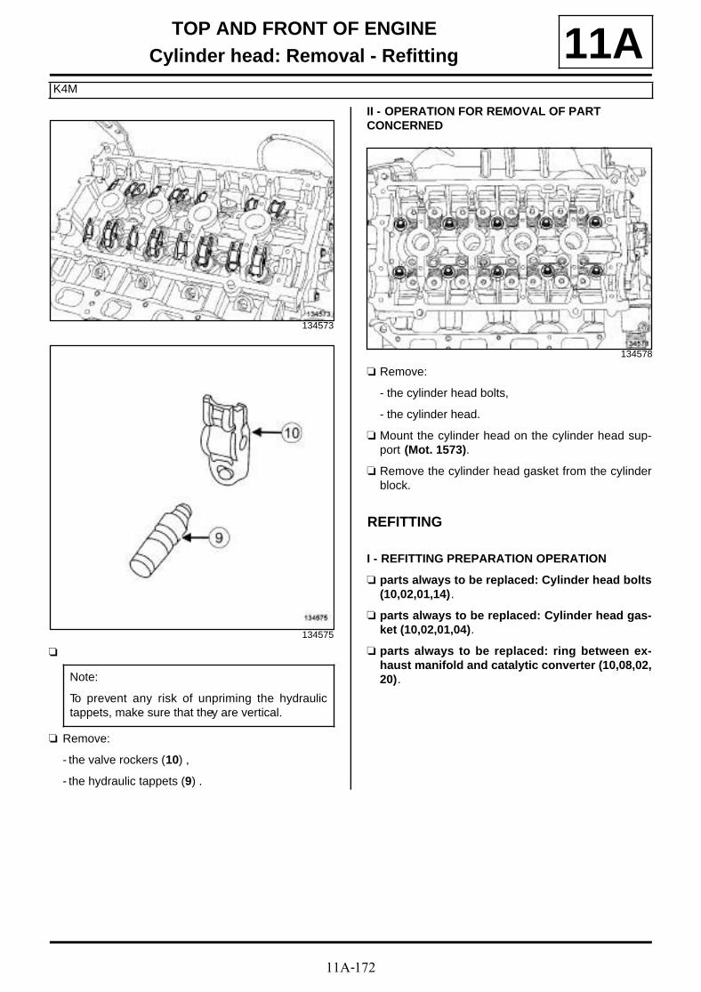
11A-172
TOP AND FRONT OF ENGINECylinder head: Removal - Refitting
K4M
11A
a
a Remove:
- the valve rockers (10) ,
- the hydraulic tappets (9) .
II - OPERATION FOR REMOVAL OF PART CONCERNED
a Remove:
- the cylinder head bolts,
- the cylinder head.
a Mount the cylinder head on the cylinder head sup-port (Mot. 1573).
a Remove the cylinder head gasket from the cylinderblock.
REFITTING
I - REFITTING PREPARATION OPERATION
a parts always to be replaced: Cylinder head bolts(10,02,01,14).
a parts always to be replaced: Cylinder head gas-ket (10,02,01,04).
a parts always to be replaced: ring between ex-haust manifold and catalytic converter (10,08,02,20).
134573
134575
Note:
To prevent any risk of unpriming the hydraulictappets, make sure that they are vertical.
134578
11A-173
TOP AND FRONT OF ENGINECylinder head: Removal - Refitting
K4M
11A1 - Cleaning the cylinder head joint face
a
a Use SUPER CLEANING AGENT FOR JOINT FA-CES (see Vehicle: Parts and ingredients for the repairwork) (04B, Consumables - Products) to clean:
- the cylinder head gasket face if being reused,
- the cylinder block gasket face.
a Use SURFACE CLEANER (see Vehicle: Parts and ingredients for the repairwork) (04B, Consu-mables - Products) to degrease:
- the cylinder head gasket face if being reused,
- the cylinder block gasket face.
2 - Checking the gasket face
a Check for gasket face deformation using a ruler anda set of shims.
a The maximum deformation is 0.05 mm.
II - REFITTING OPERATION FOR PART CONCERNED
a Bring the pistons to mid-stroke position to preventany risk of contact with the valves when tighteningthe cylinder head.
IMPORTANT
Wear goggles with side protectors for this opera-tion.
IMPORTANTWear leaktight gloves (Nitrile type) for this opera-tion.
WARNING
Do not scrape the joint faces of the aluminium,any damage caused to the joint face will result ina risk of leaks.
WARNING
Do not allow this product to drip onto the pain-twork.
Clean the cylinder head carefully to avoid anyforeign bodies entering the oil return and supplypipes.
Failure to follow this advice could lead to theblocking of the various oil inlet galleries, whichwould quickly result in engine damage.
WARNING
To ensure proper sealing, the gasket surfacesmust be clean, dry and not greasy (avoid any fin-ger marks).
WARNING
Protect the oilway so that foreign bodies do notenter the oil pipes in the cylinder head.
Failure to follow this instruction could lead to theblocking of the oilways, resulting in a rapid dete-rioration of the camshaft.
WARNING
No regrinding of the cylinder head is permitted.
Note:
If the cylinder head is faulty:
- strip down the cylinder head (see Stripping thecylinder head) (Technical Note 6023A, 10A,Engine and peripherals),
- test the cylinder head in order to detect anypossible cracks using the cylinder head test kit(see Cylinder head testing equipment: Use)(Technical Note 6026A, 11A, Top and front ofengine),
- rebuild the cylinder head (see Rebuilding thecylinder head) (Technical Note 6023A, 10A,Engine and peripherals).
WARNING
To ensure proper sealing, the gasket surfacesmust be clean, dry and not greasy (avoid any fin-ger marks).

11A-174
TOP AND FRONT OF ENGINECylinder head: Removal - Refitting
K4M
11Aa Fit:
- a new cylinder head gasket,
- the cylinder head equipped with new bolts on thecylinder block.
a Check that the centring dowel is present on the cy-linder block.
a Without tightening, fit the cylinder head bolts in or-der.
a Pretighten in order and to torque the new cylinderhead bolts (initial torque) (20 N.m).
a Check that all new cylinder head bolts are tightenedto the correct torque 20 N.m.
a Angle tighten in order the new cylinder head bolts(240˚ ±±±± 6˚).
III - FINAL OPERATION
a
a Reprime the hydraulic tappets (hydraulic tappetsmay empty after a long down time).
a To check if repriming is necessary, press the top ofthe tappet (11) with your thumb.
a If the tappet piston sinks, dip the tappet in a contai-ner filled with diesel.
a Press on the top of the tappet to expel air bubbles.
a Refit:
- the hydraulic thrust bearings,
- the valve rockers.
a Fit the engine wiring channel.
a Refit the bolts of the engine wiring channel.
a Connect the crankshaft position sensor connector.
a Clip on the wiring of the injector holder shim.
a Connect:
- the upstream oxygen sensor connector,
WARNING
In order to ensure that the bolts are correctlytightened, use a syringe to remove any oil whichmay be in the cylinder head mounting holes.
WARNING
Do not oil the new bolts. Be sure to oil boltsbeing reused.
134578
Note:
Do not retighten the cylinder head bolts afterapplying this procedure.
14499
Note:
Because this engine is equipped with hydraulictappets, there is no valve clearance adjustment.
K4M, and 848

11A-175
TOP AND FRONT OF ENGINECylinder head: Removal - Refitting
K4M
11A- the coolant temperature sensor connector,
- the hose to the heater matrix,
- the top hose to the water chamber.
a Using the (Mot. 1448) or (Mot. 1202-01) or (Mot. 1202-02) fit:
- the clip on the heater matrix hose,
- the top hose clip on the water chamber.
a Refit:
- the injector rail (see 17B, Petrol injection, Injec-tor rail - Injectors: Removal - Refitting, page17B-19) ,
- the camshafts (see 11A, Top and front of engine,Camshaft: Removal - Refitting, page 11A-114) ,
- the rocker cover (see 11A, Top and front of engi-ne, Rocker cover: Removal - Refitting, page11A-88) ,
- the oil separator (see 11A, Top and front of engi-ne, Oil decanter: Removal - Refitting, page 11A-205) .
a Refit:
- the camshaft dephaser (see 11A, Top and front ofengine, Camshaft dephaser: Removal - Refit-ting, page 11A-177) ,
- the camshaft dephaser solenoid valve (see 11A,Top and front of engine, Camshaft dephasersolenoid valve: Removal - Refitting, page 11A-184) ,
- the camshaft position sensor (see 17B, Petrol in-jection, Camshaft position sensor: Removal -Refitting, page 17B-13) .
a Refit:
- the camshaft seals (see 11A, Top and front of en-gine, Camshaft seal at timing end: Removal -Refitting, page 11A-186) ,
- the lifting eye.
a Torque tighten the lifting eye bolts (10 N.m).
a Fit the engine wiring on the lifting eye.
a Refit the dipstick guide.
a Torque tighten the dipstick guide tube bolt (10N.m).
a Clip the wiring onto the lifting eye.
a Refit:
- the spark plugs (see 17A, Ignition, Spark plugs:Removal - Refitting, page 17A-5) ,
- the ignition coils (see 17A, Ignition, Coils Remo-val - Refitting, page 17A-1) ,
- the inlet manifold (see 12A, Fuel mixture, Inletmanifold: Removal - Refitting, page 12A-23) ,
- the timing belt (see 11A, Top and front of engine,Timing belt: Removal - Refitting, page 11A-29) ,
- the exhaust manifold stay,
- a new ring between the exhaust manifold and thecatalytic converter,
- the exhaust bracket,
- the crankshaft accessories pulley (see 11A, Topand front of engine, Crankshaft accessoriespulley: Removal - Refitting, page 11A-15) ,
- the right-hand suspended engine mounting (see19D, Engine mounting, Right-hand suspendedengine mounting: Removal - Refitting, page19D-18) ,
- the accessories belt (see 11A, Top and front ofengine, Accessories belt: Removal - Refitting,page 11A-7) ,
- the lower engine tie-bar (see 19D, Engine moun-ting, Lower engine tie-bar: Removal - Refitting,page 19D-33) ,
- the front bumper (see Front bumper: Removal -Refitting) (55A, Exterior protection),
- the engine undertray,
- the front section of the front wheel arch liners (seeFront wheel arch liner: Removal - Refitting)(55A, Exterior protection),
- the front wheels (see Wheel: Removal - Refitting)(35A, Wheels and tyres),
- the scoop under the scuttle panel grille (see Scoopunder scuttle panel grille: Removal - Refitting)(56A, Exterior equipment),
K4M, and 858 or 866
K4M, and 848
11A-176
TOP AND FRONT OF ENGINECylinder head: Removal - Refitting
K4M
11A- the scuttle panel grille (see Scuttle panel grille:Removal - Refitting) (56A, Exterior equipment),
- the windscreen wiper arms (see Windscreen wi-per arm: Removal - Refitting) (85A, Wiping -Washing),
- the throttle valve (see 12A, Fuel mixture, Throttlevalve: Removal - Refitting, page 12A-17) ,
- the engine cover.
a Connect the battery (see Battery: Removal - Refit-ting) (80A, Battery).
a Fill and bleed the cooling system (see 19A, Coo-ling, Cooling circuit: Draining - Refilling, page19A-17) .

11A-177
TOP AND FRONT OF ENGINECamshaft dephaser: Removal - Refitting
K4M, and 858 or 866
11A
REMOVAL
I - REMOVAL PREPARATION OPERATION
a Position the vehicle on a two-post lift (see Vehicle:Towing and lifting) (02A, Lifting equipment).
a Disconnect the battery (see Battery: Removal - Re-fitting) (80A, Battery).
a Remove:
- the engine cover,
- the throttle valve (see 12A, Fuel mixture, Throttlevalve: Removal - Refitting, page 12A-17) ,
- the windscreen wiper arms (see Windscreen wi-per arm: Removal - Refitting) (85A, Wiping -Washing),
- the scuttle panel grille (see Scuttle panel grille:Removal - Refitting) (56A, Exterior equipment),
- the scoop under the scuttle panel grille (see Scoopunder scuttle panel grille: Removal - Refitting)(56A, Exterior equipment),
- the front right-hand wheel (see Wheel: Removal -Refitting) (35A, Wheels and tyres),
- the front section of the front right-hand wheel archliner (see Front wheel arch liner: Removal - Re-fitting) (55A, Exterior protection),
- the engine undertray bolts,
- the engine undertray,
- the lower engine tie-bar (see 19D, Engine moun-ting, Lower engine tie-bar: Removal - Refitting,page 19D-33) ,
- the accessories belt (see 11A, Top and front ofengine, Accessories belt: Removal - Refitting,page 11A-7) ,
- the right-hand suspended engine mounting (see19D, Engine mounting, Right-hand suspendedengine mounting: Removal - Refitting, page19D-18) ,
- the crankshaft accessories pulley (see 11A, Topand front of engine, Crankshaft accessoriespulley: Removal - Refitting, page 11A-15) ,
- the timing belt (see 11A, Top and front of engine,Timing belt: Removal - Refitting, page 11A-29) .
II - OPERATION FOR REMOVAL OF PART CONCERNED
a Position the tool (Mot. 1490-01) (1) on the camshaftpulleys.
a Remove the camshaft dephaser blanking cover (2) .
Essential special tooling
Mot. 1490-01 Locking and adjusting cams-haft pulleys.
Tightening torquesm
new nut on the exhaustcamshaft pulley
30 N.m + 84˚
new bolt on the cams-haft dephaser
100 N.m
136530

11A-178
TOP AND FRONT OF ENGINECamshaft dephaser: Removal - Refitting
K4M, and 858 or 866
11A
a Undo:
- the camshaft dephaser bolt (3) ,
- the exhaust camshaft sprocket nut (4) .
a Remove the tool (Mot. 1490-01) from the camshaftpulleys.
a Remove:
- the exhaust camshaft pulley nut,
- the exhaust camshaft pulley.
- the camshaft dephaser bolt,
- the camshaft dephaser.
REFITTING
I - REFITTING PREPARATION OPERATION
a parts always to be replaced: Camshaft dephasersprocket bolt (10,02,02,06).
a parts always to be replaced: Exhaust camshaftpulley nut (10,02,02,13).
a If fitting a new camshaft dephaser, check that it islocked by following the procedure described below:
a Fit a stud to the camshaft dephaser hub and tightenit.
a Place the camshaft dephaser in a vice fitted withjaws.
a Mechanically lock the camshaft dephaser by rotatingit to the left or right using a tubular hexagon boxspanner.
a Check that the camshaft dephaser is correctly loc-ked (no rotation of the hub in relation to the wheel tothe left or right).
a If there is a rotation of the hub in relation to thewheel, the camshaft dephaser is faulty and must bereplaced.
103264
WARNING
Failure to adhere to the following procedure maycause the timing belt to be incorrectly timed.
111339
111340

11A-179
TOP AND FRONT OF ENGINECamshaft dephaser: Removal - Refitting
K4M, and 858 or 866
11Aa Degrease the end of the camshaft (timing end) and
clean the bores and bearing faces of the camshaftdephaser.
II - REFITTING OPERATION FOR PART CONCERNED
a Refit:
- the exhaust camshaft pulley.
- the camshaft dephaser,
- a new nut on the exhaust camshaft pulley,
- a new bolt on the camshaft dephaser.
a Position the tool (Mot. 1490-01) on the camshaftpulleys.
a Tighten to torque:
- the new nut on the exhaust camshaft pulley (30N.m + 84˚),
- the new bolt on the camshaft dephaser (100N.m).
a Refit the blanking cover on the camshaft dephaser.
a Remove the tool (Mot. 1490-01) from the camshaftpulleys.
III - FINAL OPERATION
a Refit:
- the timing belt (see 11A, Top and front of engine,Timing belt: Removal - Refitting, page 11A-29) ,
- the crankshaft accessories pulley (see 11A, Topand front of engine, Crankshaft accessoriespulley: Removal - Refitting, page 11A-15) ,
- the right-hand suspended engine mounting (see19D, Engine mounting, Right-hand suspendedengine mounting: Removal - Refitting, page19D-18) ,
- the accessories belt (see 11A, Top and front ofengine, Accessories belt: Removal - Refitting,page 11A-7) ,
- the lower engine tie-bar (see 19D, Engine moun-ting, Lower engine tie-bar: Removal - Refitting,page 19D-33) ,
- the engine undertray,
- the front section of the front right-hand wheel archliner (see Front wheel arch liner: Removal - Re-fitting) (55A, Exterior protection),
- the front right-hand wheel (see Wheel: Removal -Refitting) (35A, Wheels and tyres),
- the scoop under the scuttle panel grille (see Scoopunder scuttle panel grille: Removal - Refitting)(56A, Exterior equipment),
- the scuttle panel grille (see Scuttle panel grille:Removal - Refitting) (56A, Exterior equipment),
- the windscreen wiper arms (see Windscreen wi-per arm: Removal - Refitting) (85A, Wiping -Washing),
- the throttle valve (see 12A, Fuel mixture, Throttlevalve: Removal - Refitting, page 12A-17) ,
- the engine cover.
a Connect the battery (see Battery: Removal - Refit-ting) (80A, Battery).

11A-180
TOP AND FRONT OF ENGINECamshaft dephaser: Removal - Refitting
F4R
11A
REMOVAL
I - REMOVAL PREPARATION OPERATION
a Position the vehicle on a two-post lift (see Vehicle:Towing and lifting) (02A, Lifting equipment).
a Remove:
- the engine cover,
- the battery (see Battery: Removal - Refitting)(80A, Battery),
- the battery tray (see Battery tray: Removal - Re-fitting) (80A, Battery),
- the engine undertray bolts,
- the engine undertray,
- the front wheels (see Wheel: Removal - Refitting)(35A, Wheels and tyres),
- the front section of the front wheel arch liners (seeFront wheel arch liner: Removal - Refitting)(55A, Exterior protection),
- the front bumper (see Front bumper: Removal -Refitting) (55A, Exterior protection),
- the radiator mounting cross member (see Radiatorsupport cross member: Removal - Refitting)(31A, Front axle components),
- the accessories belt (see 11A, Top and front ofengine, Accessories belt: Removal - Refitting,page 11A-7) ,
- the crankshaft accessories pulley (see 11A, Topand front of engine, Crankshaft accessoriespulley: Removal - Refitting, page 11A-15) ,
- the lower engine tie-bar (see 19D, Engine moun-ting, Lower engine tie-bar: Removal - Refitting,page 19D-33) ,
- the windscreen wiper arms (see Windscreen wi-per arm: Removal - Refitting) (85A, Wiping -Washing),
- the scuttle panel grille (see Scuttle panel grille:Removal - Refitting) (56A, Exterior equipment),
- the scoop under the scuttle panel grille (see Scoopunder scuttle panel grille: Removal - Refitting)(56A, Exterior equipment),
- the right-hand suspended engine mounting (see19D, Engine mounting, Right-hand suspendedengine mounting: Removal - Refitting, page19D-18) ,
- the timing belt (see 11A, Top and front of engine,Timing belt: Removal - Refitting, page 11A-29) .
II - OPERATION FOR REMOVAL OF PART CONCERNED
a Position the (Mot. 1801) (1) .
a Remove the camshaft dephaser blanking cover (2) .
Essential special tooling
Mot. 1801 Camshaft sprocket lockingtool - F4 engine.
Tightening torquesm
camshaft dephaser bolt 100 N.m
new blanking cover onthe camshaft dephaser
15 N.m
117346

11A-181
TOP AND FRONT OF ENGINECamshaft dephaser: Removal - Refitting
F4R
11A
a Remove:
- the camshaft dephaser bolt (3) ,
- the (Mot. 1801),
- the inlet camshaft dephaser.
REFITTING
I - REFITTING PREPARATION OPERATION
a parts always to be replaced: Camshaft dephasersprocket bolt (10,02,02,19).
a parts always to be replaced: camshaft dephasersprocket blanking cover (10,02,02,20).
a
a If fitting a new inlet camshaft dephaser, check that itis locked by following the procedure described be-low.
a Fit the camshaft dephaser into a vice with jaws.
135741
WARNING
Always degrease:
- the end of the crankshaft (timing end),
- the timing sprocket bore and bearing faces,
- the crankshaft accessories pulley bearingfaces,
- the camshaft ends (timing end),
- the camshaft sprocket bores and bearing faces.
This is to avoid timing slippage.
This slippage leads to engine damage.
Note:
Failure to adhere to the following procedure maycause the timing belt to be incorrectly timed.
111338

11A-182
TOP AND FRONT OF ENGINECamshaft dephaser: Removal - Refitting
F4R
11A
a Fit a stud on the camshaft dephaser hub.
a Check that the camshaft dephaser hub is correctlymechanically secured using a tubular hexagon boxspanner (the hub must not be able to rotate to theleft or right).
II - REFITTING OPERATION FOR PART CONCERNED
a Refit:
- the camshaft dephaser,
- the camshaft dephaser bolt.
a Position the (Mot. 1801).
a Torque tighten the camshaft dephaser bolt (100N.m).
a Fit a new blanking cover on the camshaft dephaser.
a Torque tighten the new blanking cover on thecamshaft dephaser (15 N.m).
a Remove the (Mot. 1801).
III - FINAL OPERATION
a Refit:
- the timing belt (see 11A, Top and front of engine,Timing belt: Removal - Refitting, page 11A-29) ,
- the right-hand suspended engine mounting (see19D, Engine mounting, Right-hand suspendedengine mounting: Removal - Refitting, page19D-18) ,
- the scoop under the scuttle panel grille (see Scoopunder scuttle panel grille: Removal - Refitting)(56A, Exterior equipment),
- the scuttle panel grille (see Scuttle panel grille:Removal - Refitting) (56A, Exterior equipment),
- the windscreen wiper arms (see Windscreen wi-per arm: Removal - Refitting) (85A, Wiping -Washing),
- the engine tie-bar (see 19D, Engine mounting,Lower engine tie-bar: Removal - Refitting, page19D-33) ,
- the crankshaft accessories pulley (see 11A, Topand front of engine, Crankshaft accessoriespulley: Removal - Refitting, page 11A-15) ,
- the accessories belt (see 11A, Top and front ofengine, Accessories belt: Removal - Refitting,page 11A-7) ,
- the radiator mounting cross member (see Radiatorsupport cross member: Removal - Refitting)(31A, Front axle components),
- the front bumper (see Front bumper: Removal -Refitting) (55A, Exterior protection),
- the front section of the front wheel arch liners (seeFront wheel arch liner: Removal - Refitting)(55A, Exterior protection),
- the front wheels (see Wheel: Removal - Refitting)(35A, Wheels and tyres),
- the engine undertray,
- the battery tray (see Battery tray: Removal - Re-fitting) (80A, Battery),
111339
111340

11A-183
TOP AND FRONT OF ENGINECamshaft dephaser: Removal - Refitting
F4R
11A- the battery (see Battery: Removal - Refitting)(80A, Battery),
- the engine cover.
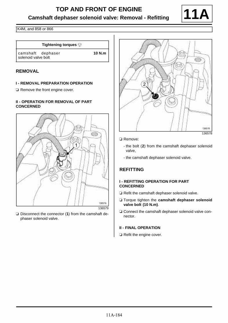
11A-184
TOP AND FRONT OF ENGINECamshaft dephaser solenoid valve: Removal - Refitting
K4M, and 858 or 866
11A
REMOVAL
I - REMOVAL PREPARATION OPERATION
a Remove the front engine cover.
II - OPERATION FOR REMOVAL OF PART CONCERNED
a Disconnect the connector (1) from the camshaft de-phaser solenoid valve.
a Remove:
- the bolt (2) from the camshaft dephaser solenoidvalve,
- the camshaft dephaser solenoid valve.
REFITTING
I - REFITTING OPERATION FOR PART CONCERNED
a Refit the camshaft dephaser solenoid valve.
a Torque tighten the camshaft dephaser solenoidvalve bolt (10 N.m).
a Connect the camshaft dephaser solenoid valve con-nector.
II - FINAL OPERATION
a Refit the engine cover.
Tightening torquesm
camshaft dephasersolenoid valve bolt
10 N.m
136579
136578

11A-185
TOP AND FRONT OF ENGINECamshaft dephaser solenoid valve: Removal - Refitting
F4R
11A
REMOVAL
I - REMOVAL PREPARATION OPERATION
a Remove the front engine cover.
II - OPERATION FOR REMOVAL OF PART CONCERNED
a Disconnect the connector (1) from the camshaft de-phaser solenoid valve.
a Remove the bolt (2) of the camshaft dephaser sole-noid valve.
a Move aside the coil of cylinder no. 4.
a Remove the camshaft dephaser solenoid valve.
REFITTING
I - REFITTING OPERATION FOR PART CONCERNED
a Refit the camshaft dephaser solenoid valve.
a Torque tighten the camshaft dephaser solenoidvalve bolt (10 N.m).
a Connect the camshaft dephaser solenoid valve con-nector.
II - FINAL OPERATION
a Refit the engine cover.
Tightening torquesm
camshaft dephasersolenoid valve bolt
10 N.m
135750
135749
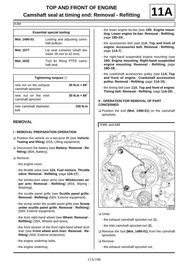
11A-186
TOP AND FRONT OF ENGINECamshaft seal at timing end: Removal - Refitting
K4M
11A
REMOVAL
I - REMOVAL PREPARATION OPERATION
a Position the vehicle on a two-post lift (see Vehicle:Towing and lifting) (02A, Lifting equipment).
a Disconnect the battery (see Battery: Removal - Re-fitting) (80A, Battery).
a Remove:
- the engine cover,
- the throttle valve (see 12A, Fuel mixture, Throttlevalve: Removal - Refitting, page 12A-17) ,
- the windscreen wiper arms (see Windscreen wi-per arm: Removal - Refitting) (85A, Wiping -Washing),
- the scuttle panel grille (see Scuttle panel grille:Removal - Refitting) (56A, Exterior equipment),
- the scoop under the scuttle panel grille (see Scoopunder scuttle panel grille: Removal - Refitting)(56A, Exterior equipment),
- the front right-hand wheel (see Wheel: Removal -Refitting) (35A, Wheels and tyres),
- the front section of the front right-hand wheel archliner (see Front wheel arch liner: Removal - Re-fitting) (55A, Exterior protection),
- the engine undertray bolts,
- the engine undertray,
- the lower engine tie-bar (see 19D, Engine moun-ting, Lower engine tie-bar: Removal - Refitting,page 19D-33) ,
- the accessories belt (see 11A, Top and front ofengine, Accessories belt: Removal - Refitting,page 11A-7) ,
- the right-hand suspended engine mounting (see19D, Engine mounting, Right-hand suspendedengine mounting: Removal - Refitting, page19D-18) ,
- the crankshaft accessories pulley (see 11A, Topand front of engine, Crankshaft accessoriespulley: Removal - Refitting, page 11A-15) ,
- the timing belt (see 11A, Top and front of engine,Timing belt: Removal - Refitting, page 11A-29) ,
II - OPERATION FOR REMOVAL OF PART CONCERNED
a Position the tool (Mot. 1490-01) on the camshaftsprockets.
a Undo:
- the exhaust camshaft sprocket nut (1) ,
- the inlet camshaft sprocket nut (2) .
a Remove the tool (Mot. 1490-01) from the camshaftsprockets.
a Remove:
- the exhaust camshaft sprocket nut,
Essential special tooling
Mot. 1490-01 Locking and adjusting cams-haft pulleys.
Mot. 1577 Lip seal extractor (shaft dia-meter 28 mm to 42 mm).
Mot. 1632 Tool for fitting PTFE cams-haft seal
Tightening torquesm
new nut on the exhaustcamshaft sprocket
30 N.m + 84˚
new nut on the inletcamshaft sprocket
30 N.m + 84˚
new camshaft dephaserbolt
100 N.m
K4M, and 848
135235
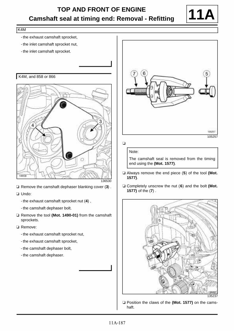
11A-187
TOP AND FRONT OF ENGINECamshaft seal at timing end: Removal - Refitting
K4M
11A- the exhaust camshaft sprocket,
- the inlet camshaft sprocket nut,
- the inlet camshaft sprocket.
a Remove the camshaft dephaser blanking cover (3) .
a Undo:
- the exhaust camshaft sprocket nut (4) ,
- the camshaft dephaser bolt.
a Remove the tool (Mot. 1490-01) from the camshaftsprockets.
a Remove:
- the exhaust camshaft sprocket nut,
- the exhaust camshaft sprocket,
- the camshaft dephaser bolt,
- the camshaft dephaser.
a
a Always remove the end piece (5) of the tool (Mot.1577).
a Completely unscrew the nut (6) and the bolt (Mot.1577) of the (7) .
a Position the claws of the (Mot. 1577) on the cams-haft.
K4M, and 858 or 866
136530
105257
Note:
The camshaft seal is removed from the timingend using the (Mot. 1577).
135237
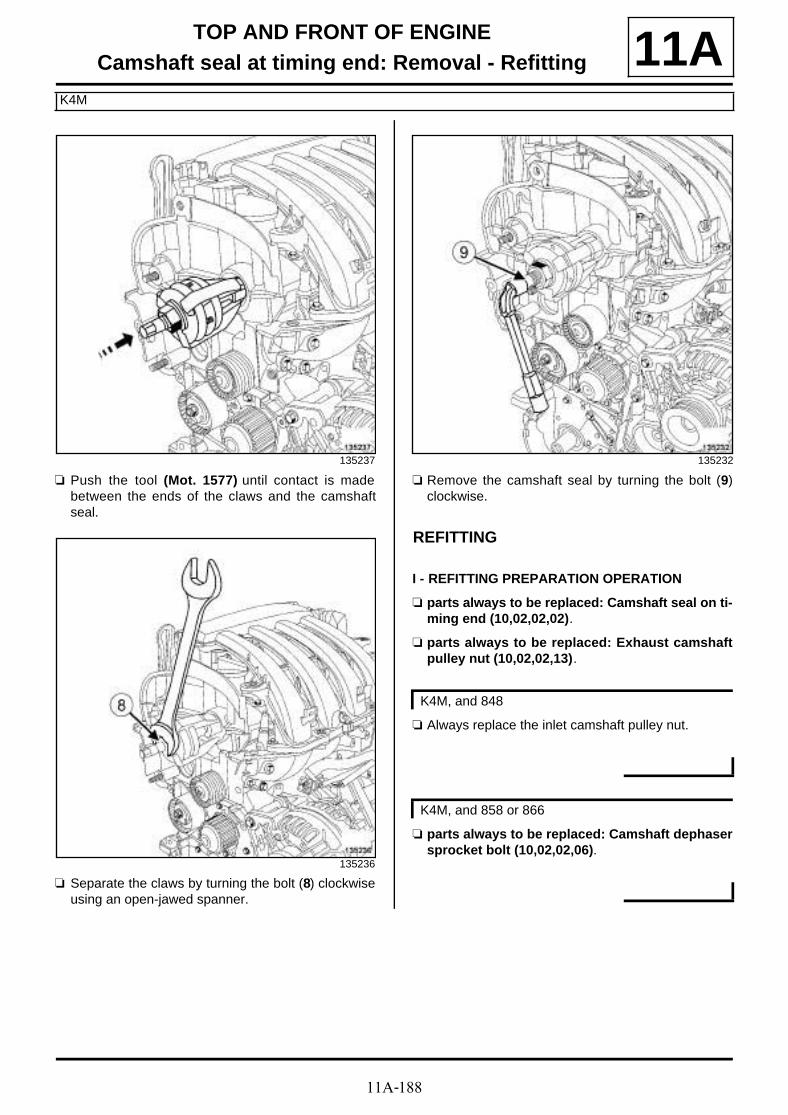
11A-188
TOP AND FRONT OF ENGINECamshaft seal at timing end: Removal - Refitting
K4M
11A
a Push the tool (Mot. 1577) until contact is madebetween the ends of the claws and the camshaftseal.
a Separate the claws by turning the bolt (8) clockwiseusing an open-jawed spanner.
a Remove the camshaft seal by turning the bolt (9)clockwise.
REFITTING
I - REFITTING PREPARATION OPERATION
a parts always to be replaced: Camshaft seal on ti-ming end (10,02,02,02).
a parts always to be replaced: Exhaust camshaftpulley nut (10,02,02,13).
a Always replace the inlet camshaft pulley nut.
a parts always to be replaced: Camshaft dephasersprocket bolt (10,02,02,06).
135237
135236
135232
K4M, and 848
K4M, and 858 or 866

11A-189
TOP AND FRONT OF ENGINECamshaft seal at timing end: Removal - Refitting
K4M
11Aa Degrease the bearing surfaces of the timing end
camshaft seals using SURFACE CLEANER (see Vehicle: Parts and ingredients for the repai-rwork) (04B, Consumables - Products):
- the seal mating face of each camshaft,
- the camshaft seal housings.
II - REFITTING OPERATION FOR PART CONCERNED
a
a Fit the protector fitted with a new seal (13) on the in-let and exhaust camshaft, taking care not to touchthe seal.
a Screw on the stud (12) of the tool (Mot. 1632) on theinlet and exhaust camshafts.
WARNING
Do not scrape the joint faces of the aluminium,any damage caused to the joint face will result ina risk of leaks.
WARNING
To ensure proper sealing, the gasket surfacesmust be clean, dry and not greasy (avoid any fin-ger marks).
18687
Note:
Always hold the camshaft seal with the protector(10) when handling, as this type of seal is veryFRAGILE. It is strictly forbidden to touch the seal(11) in order to prevent any oil leaks once thecamshaft seal is fitted to the engine.
105531
135231
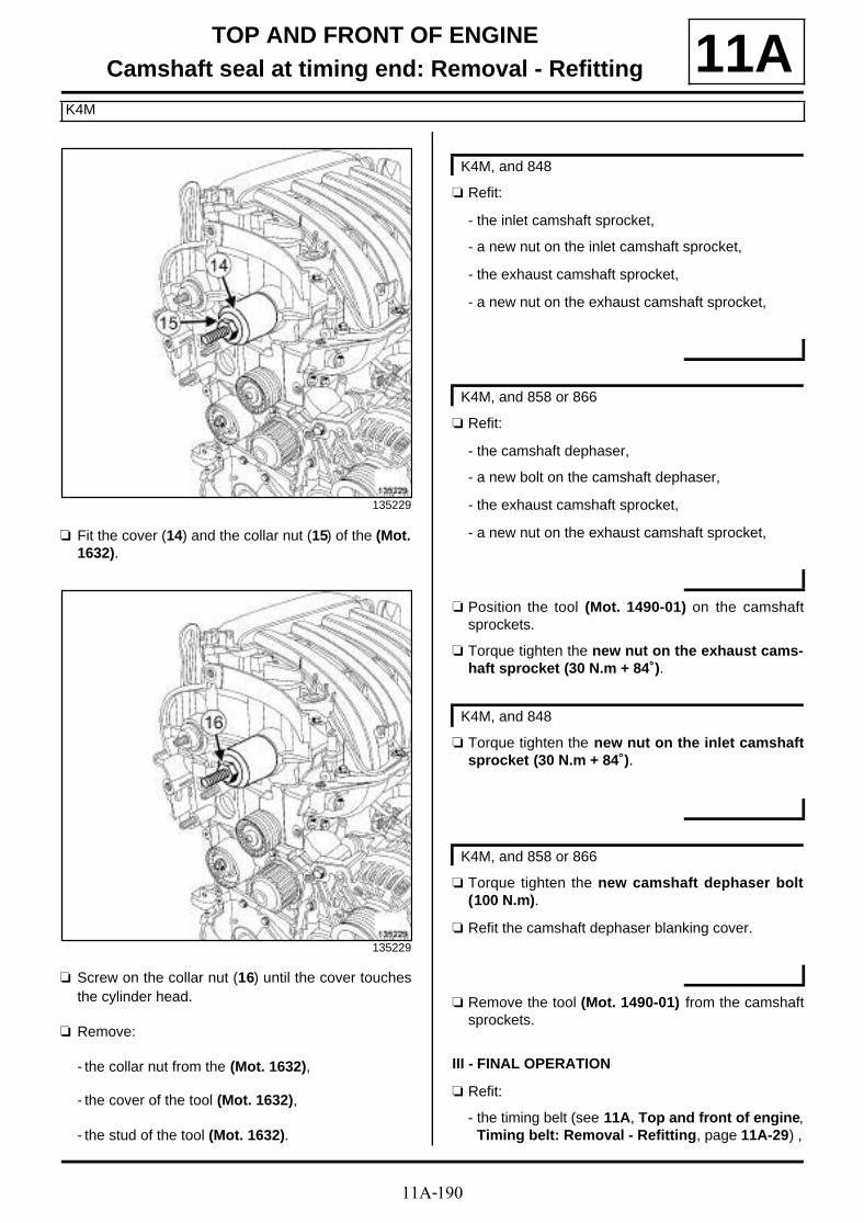
11A-190
TOP AND FRONT OF ENGINECamshaft seal at timing end: Removal - Refitting
K4M
11A
a Fit the cover (14) and the collar nut (15) of the (Mot.1632).
a Screw on the collar nut (16) until the cover touchesthe cylinder head.
a Remove:
- the collar nut from the (Mot. 1632),
- the cover of the tool (Mot. 1632),
- the stud of the tool (Mot. 1632).
a Refit:
- the inlet camshaft sprocket,
- a new nut on the inlet camshaft sprocket,
- the exhaust camshaft sprocket,
- a new nut on the exhaust camshaft sprocket,
a Refit:
- the camshaft dephaser,
- a new bolt on the camshaft dephaser,
- the exhaust camshaft sprocket,
- a new nut on the exhaust camshaft sprocket,
a Position the tool (Mot. 1490-01) on the camshaftsprockets.
a Torque tighten the new nut on the exhaust cams-haft sprocket (30 N.m + 84˚).
a Torque tighten the new nut on the inlet camshaftsprocket (30 N.m + 84˚).
a Torque tighten the new camshaft dephaser bolt(100 N.m).
a Refit the camshaft dephaser blanking cover.
a Remove the tool (Mot. 1490-01) from the camshaftsprockets.
III - FINAL OPERATION
a Refit:
- the timing belt (see 11A, Top and front of engine,Timing belt: Removal - Refitting, page 11A-29) ,
135229
135229
K4M, and 848
K4M, and 858 or 866
K4M, and 848
K4M, and 858 or 866

11A-191
TOP AND FRONT OF ENGINECamshaft seal at timing end: Removal - Refitting
K4M
11A- the crankshaft accessories pulley (see 11A, Topand front of engine, Crankshaft accessoriespulley: Removal - Refitting, page 11A-15) ,
- the right-hand suspended engine mounting (see19D, Engine mounting, Right-hand suspendedengine mounting: Removal - Refitting, page19D-18) ,
- the accessories belt (see 11A, Top and front ofengine, Accessories belt: Removal - Refitting,page 11A-7) ,
- the lower engine tie-bar (see 19D, Engine moun-ting, Lower engine tie-bar: Removal - Refitting,page 19D-33) ,
- the engine undertray,
- the front section of the front right-hand wheel archliner (see Front wheel arch liner: Removal - Re-fitting) (55A, Exterior protection),
- the front right-hand wheel (see Wheel: Removal -Refitting) (35A, Wheels and tyres),
- the scoop under the scuttle panel grille (see Scoopunder scuttle panel grille: Removal - Refitting)(56A, Exterior equipment),
- the scuttle panel grille (see Scuttle panel grille:Removal - Refitting) (56A, Exterior equipment),
- the windscreen wiper arms (see Windscreen wi-per arm: Removal - Refitting) (85A, Wiping -Washing),
- the throttle valve (see 12A, Fuel mixture, Throttlevalve: Removal - Refitting, page 12A-17) ,
- the engine cover.
a Connect the battery (see Battery: Removal - Refit-ting) (80A, Battery).

11A-192
TOP AND FRONT OF ENGINECamshaft seal at timing end: Removal - Refitting
K9K
11A
REMOVAL
I - REMOVAL PREPARATION OPERATION
a Position the vehicle on a two-post lift (see Vehicle:Towing and lifting) (02A, Lifting equipment).
a Disconnect the battery (see Battery : Removal -Refitting) (80A, Battery).
a Remove:
- the engine cover,
- the front right-hand wheel (see Wheel: Removal -Refitting) (35A, Wheels and tyres),
- the front section of the front right-hand wheel archliner (see Front wheel arch liner: Removal - Re-fitting) (55A, Exterior protection),
- the engine undertray bolts,
- the engine undertray,
- the accessories belt (see 11A, Top and front ofengine, Accessories belt: Removal - Refitting,page 11A-7)
- the crankshaft accessories pulley (see 11A, Topand front of engine, Crankshaft accessoriespulley: Removal - Refitting, page 11A-15) ,
- the windscreen wiper arms (see Windscreen wi-per arm: Removal - Refitting) (85A, Wiping -Washing),
- the scuttle panel grille (see Scuttle panel grille:Removal - Refitting) (56A, Exterior equipment),
- the scoop under the scuttle panel grille (see Scoopunder scuttle panel grille: Removal - Refitting)(56A, Exterior equipment),
- the right-hand suspended engine mounting (see19D, Engine mounting, Right-hand suspendedengine mounting: Removal - Refitting, page19D-18) ,
- the timing belt (see 11A, Top and front of engine,Timing belt: Removal - Refitting, page 11A-29) .
a Increase the hole (1) of the (Mot. 1606) (2) using an8.5 mm drill bit.
Essential special tooling
Mot. 1606 High pressure pump-pulleyretaining tool.
Mot. 1577 Lip seal extractor (shaft dia-meter 28 mm to 42 mm).
Mot. 1632 Tool for fitting PTFE cams-haft seal
Mot. 1430 Set of 5 crankshaft and cams-haft pulley timing pins.
Essential equipment
offset spanner
Tightening torquesm
camshaft pulley nut 30 N.m + 86˚ ±±±±6˚.
118982

11A-193
TOP AND FRONT OF ENGINECamshaft seal at timing end: Removal - Refitting
K9K
11A
a Undo the camshaft pulley hub bolts (3) .
a Fit the (Mot. 1606) on the cylinder head to lock thecamshaft pulley wheel.
a Tighten the camshaft pulley hub bolts (3) .
a Remove:
- the nut (4) from the camshaft pulley,
- the (Mot. 1606),
- the camshaft pulley.
II - OPERATION FOR REMOVAL OF PART CONCERNED
a
a Loosen bolts (6) and (7) fully from the (Mot. 1577).
118983
123970
105257
Note:
The timing end camshaft seal (5) is removedusing the tool (Mot. 1577).
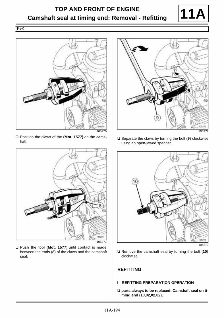
11A-194
TOP AND FRONT OF ENGINECamshaft seal at timing end: Removal - Refitting
K9K
11A
a Position the claws of the (Mot. 1577) on the cams-haft.
a Push the tool (Mot. 1577) until contact is madebetween the ends (8) of the claws and the camshaftseal.
a Separate the claws by turning the bolt (9) clockwiseusing an open-jawed spanner.
a Remove the camshaft seal by turning the bolt (10)clockwise.
REFITTING
I - REFITTING PREPARATION OPERATION
a parts always to be replaced: Camshaft seal on ti-ming end (10,02,02,02).
105270
105271
105272
105273

11A-195
TOP AND FRONT OF ENGINECamshaft seal at timing end: Removal - Refitting
K9K
11Aa parts always to be replaced: Camshaft timing
sprocket nut (10,02,02,18).
a Degrease and clean using SURFACE CLEANER (see Vehicle: Parts and ingredients for the repai-rwork) (04B, Ingredient - Products) and a CLEAN CLOTH :
- the camshaft seal mating face on the camshaft,
- the camshaft seal housing in the cylinder head.
II - REFITTING OPERATION FOR PART CONCERNED
a Screw the stud (11) of the (Mot. 1632) onto thecamshaft.
WARNING
Do not scrape the joint faces of the aluminium,any damage caused to the joint face will result ina risk of leaks.
WARNINGTo ensure proper sealing, the gasket surfacesmust be clean, dry and not greasy (avoid any fin-ger marks).
105531
21687

11A-196
TOP AND FRONT OF ENGINECamshaft seal at timing end: Removal - Refitting
K9K
11A
a Fit a new camshaft seal on the camshaft.
1 - First fitting of the camshaft seal
a Fit the cover (12) and the collar nut (13) of the (Mot.1632).
a Screw on the collar nut until the cover touches thecylinder head.
a Remove:
- the collar nut from the (Mot. 1632),
- the cover from the (Mot. 1632),
- the stud of the (Mot. 1632),
- the protective sleeve.
21687-1
Note:
For camshaft seals delivered fitted to a protectivesleeve:
-do not remove the camshaft seal from its protec-tive sleeve,
-fit the sleeve fitted with the camshaft seal on thecamshaft,
-push the protective sleeve towards the cylinderhead until the camshaft seal is in full contact withthe cylinder head,
-fit the seal on the camshaft by following therecommendations below.
21687-2
21687-3

11A-197
TOP AND FRONT OF ENGINECamshaft seal at timing end: Removal - Refitting
K9K
11A2 - Second fitting of the camshaft seal
a Depending on the case, the Parts Department deli-vers seals (14) equipped with a spacer (15) amongstother things.
a
a Fit the cover (19) equipped with the spacer on thecamshaft seal end and the collar nut (20) of the tool(Mot. 1632).
a Screw on the collar nut until the spacer fitted on thecover touches the cylinder head.
123076
123075
Note:
The spacer (16) is used to fit the seal (17) . It isused with the tool (Mot. 1632) (18) .
21687-2
Note:
The spacer fits on the cover of the tool (Mot.1632) so that the edge of the spacer is on theside of the camshaft seal.
21687-3
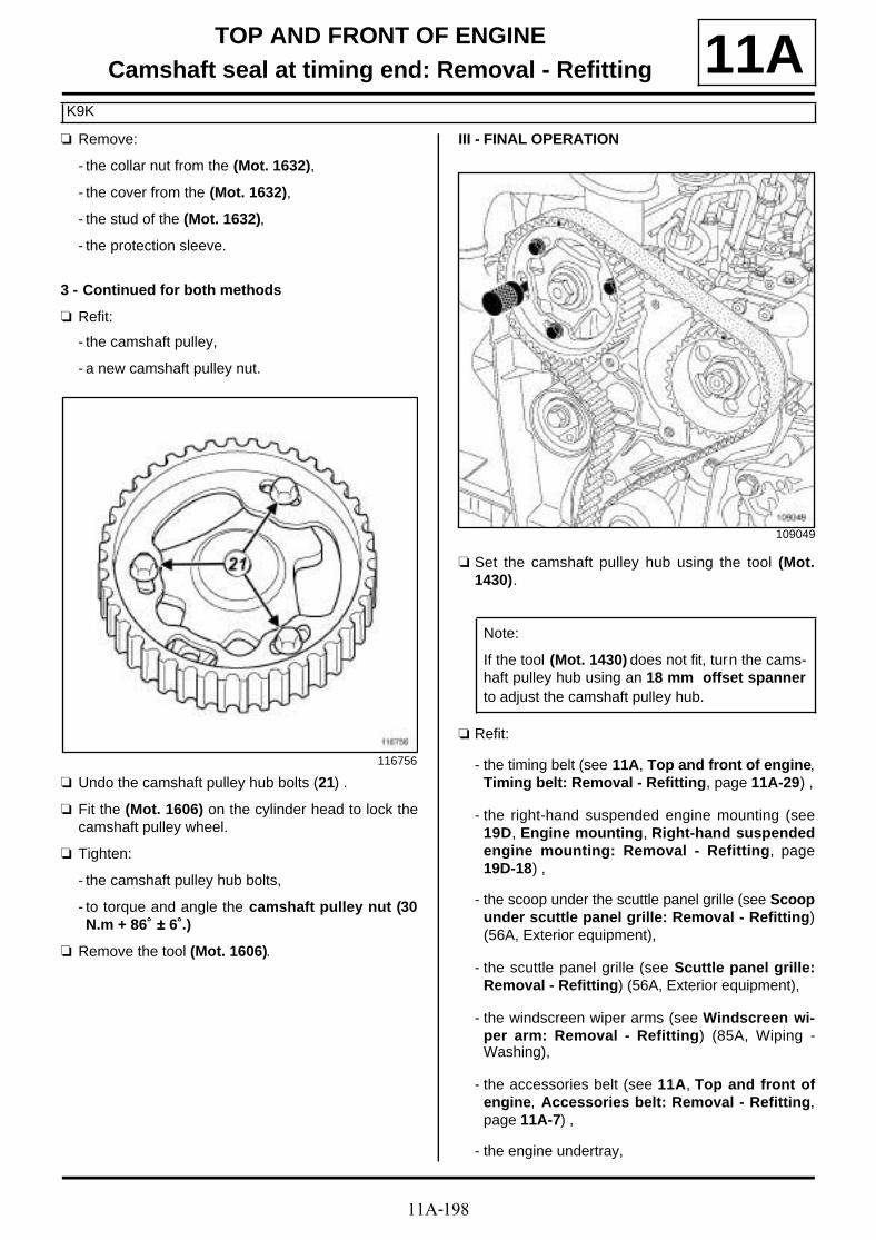
11A-198
TOP AND FRONT OF ENGINECamshaft seal at timing end: Removal - Refitting
K9K
11Aa Remove:
- the collar nut from the (Mot. 1632),
- the cover from the (Mot. 1632),
- the stud of the (Mot. 1632),
- the protection sleeve.
3 - Continued for both methods
a Refit:
- the camshaft pulley,
- a new camshaft pulley nut.
a Undo the camshaft pulley hub bolts (21) .
a Fit the (Mot. 1606) on the cylinder head to lock thecamshaft pulley wheel.
a Tighten:
- the camshaft pulley hub bolts,
- to torque and angle the camshaft pulley nut (30N.m + 86˚ ±±±± 6˚.)
a Remove the tool (Mot. 1606).
III - FINAL OPERATION
a Set the camshaft pulley hub using the tool (Mot.1430).
a Refit:
- the timing belt (see 11A, Top and front of engine,Timing belt: Removal - Refitting, page 11A-29) ,
- the right-hand suspended engine mounting (see19D, Engine mounting, Right-hand suspendedengine mounting: Removal - Refitting, page19D-18) ,
- the scoop under the scuttle panel grille (see Scoopunder scuttle panel grille: Removal - Refitting)(56A, Exterior equipment),
- the scuttle panel grille (see Scuttle panel grille:Removal - Refitting) (56A, Exterior equipment),
- the windscreen wiper arms (see Windscreen wi-per arm: Removal - Refitting) (85A, Wiping -Washing),
- the accessories belt (see 11A, Top and front ofengine, Accessories belt: Removal - Refitting,page 11A-7) ,
- the engine undertray,
116756
109049
Note:
If the tool (Mot. 1430) does not fit, turn the cams-haft pulley hub using an 18 mm offset spannerto adjust the camshaft pulley hub.

11A-199
TOP AND FRONT OF ENGINECamshaft seal at timing end: Removal - Refitting
K9K
11A- the front section of the front right-hand wheel archliner (see Front wheel arch liner: Removal - Re-fitting) (55A, Exterior protection),
- the front right-hand wheel (see Wheel: Removal -Refitting) (35A, Wheels and tyres),
- the engine cover.
a Connect the battery (see Battery : Removal - Refit-ting) (80A, Battery).

11A-200
TOP AND FRONT OF ENGINECamshaft seal at timing end: Removal - Refitting
F4R
11A
REMOVAL
I - REMOVAL PREPARATION OPERATION
a Position the vehicle on a two-post lift (see Vehicle:Towing and lifting) (02A, Lifting equipment).
a Remove:
- the engine cover,
- the battery (see Battery: Removal - Refitting)(80A, Battery),
- the battery tray (see Battery tray: Removal - Re-fitting) (80A, Battery),
- the engine undertray bolts,
- the engine undertray,
- the front wheels (see Wheel: Removal - Refitting)(35A, Wheels and tyres),
- the front section of the front wheel arch liners (seeFront wheel arch liner: Removal - Refitting)(55A, Exterior protection),
- the front bumper (see Front bumper: Removal -Refitting) (55A, Exterior protection),
- the radiator mounting cross member (see Radiatorsupport cross member: Removal - Refitting)(31A, Front axle components),
- the accessories belt (see 11A, Top and front ofengine, Accessories belt: Removal - Refitting,page 11A-7) ,
- the crankshaft accessories pulley (see 11A, Topand front of engine, Crankshaft accessoriespulley: Removal - Refitting, page 11A-15) ,
- the lower engine tie-bar (see 19D, Engine moun-ting, Lower engine tie-bar: Removal - Refitting,page 19D-33) ,
- the windscreen wiper arms (see Windscreen wi-per arm: Removal - Refitting) (85A, Wiping -Washing),
- the scuttle panel grille (see Scuttle panel grille:Removal - Refitting) (56A, Exterior equipment),
- the scoop under the scuttle panel grille (see Scoopunder scuttle panel grille: Removal - Refitting)(56A, Exterior equipment),
- the right-hand suspended engine mounting (see19D, Engine mounting, Right-hand suspendedengine mounting: Removal - Refitting, page19D-18) ,
- the timing belt (see 11A, Top and front of engine,Timing belt: Removal - Refitting, page 11A-29) .
a Position the (Mot. 1801) (1) .
a Torque tighten the toothed sprocket nuts (80N.m).
a Remove:
- the exhaust camshaft pulley nut (2) ,
- the camshaft dephaser (see 11A, Top and front ofengine, Camshaft dephaser: Removal - Refit-ting, page 11A-177) (3) ,
- the (Mot. 1801),
- the exhaust camshaft pulley.
Essential special tooling
Mot. 1801 Camshaft sprocket lockingtool - F4 engine.
Mot. 1517 Camshaft seal fitting tool.
Mot. 1512 Exhaust camshaft oil seal fit-ting tool (28 x 47).
Tightening torquesm
toothed sprocket nuts 80 N.m
toothed sprocket nuts 80 N.m
exhaust camshaft pul-ley nut
30 N.m ±±±± 86˚
135741

11A-201
TOP AND FRONT OF ENGINECamshaft seal at timing end: Removal - Refitting
F4R
11AII - OPERATION FOR REMOVAL OF PART CONCERNED
a Remove the camshaft seals using a screwdriver.
REFITTING
I - REFITTING PREPARATION OPERATION
a parts always to be replaced: Camshaft seal on ti-ming end (10,02,02,02).
a parts always to be replaced: Camshaft timingsprocket nut (10,02,02,18).
a Use SURFACE CLEANER (see Vehicle: Parts and ingredients for the repairwork) (04B, Consu-mables - Products) to clean and degrease:
- the seal mating face of each camshaft,
- the cylinder head seal housings.
II - REFITTING OPERATION FOR PART CONCERNED
a Refit a new inlet camshaft seal using the tool (Mot.1517) (4) .
a Refit a new exhaust camshaft seal using the tool(Mot. 1512) (5) .
III - FINAL OPERATION
a Refit:
- the camshaft dephaser (see 11A, Top and front ofengine, Camshaft dephaser: Removal - Refit-ting, page 11A-177) ,
WARNING
Do not scrape the joint faces of the aluminium,any damage caused to the joint face will result ina risk of leaks.
WARNING
To ensure proper sealing, the gasket surfacesmust be clean, dry and not greasy (avoid any fin-ger marks).
135742
135743

11A-202
TOP AND FRONT OF ENGINECamshaft seal at timing end: Removal - Refitting
F4R
11A- the exhaust camshaft pulley.
- a new nut on the exhaust camshaft pulley.
a Tighten to torque:
- the toothed sprocket nuts (80 N.m),
- the exhaust camshaft pulley nut (30 N.m ±±±± 86 )̊.
a Remove the tool (Mot. 1801).
a Refit:
- the timing belt (see 11A, Top and front of engine,Timing belt: Removal - Refitting, page 11A-29) ,
- the right-hand suspended engine mounting (see19D, Engine mounting, Right-hand suspendedengine mounting: Removal - Refitting, page19D-18) ,
- the scoop under the scuttle panel grille (see Scoopunder scuttle panel grille: Removal - Refitting)(56A, Exterior equipment),
- the scuttle panel grille (see Scuttle panel grille:Removal - Refitting) (56A, Exterior equipment),
- the windscreen wiper arms (see Windscreen wi-per arm: Removal - Refitting) (85A, Wiping -Washing),
- the lower engine tie-bar (see 19D, Engine moun-ting, Lower engine tie-bar: Removal - Refitting,page 19D-33) ,
- the crankshaft accessories pulley (see 11A, Topand front of engine, Crankshaft accessoriespulley: Removal - Refitting, page 11A-15) ,
- the accessories belt (see 11A, Top and front ofengine, Accessories belt: Removal - Refitting,page 11A-7) ,
- the radiator mounting cross member (see Radiatorsupport cross member: Removal - Refitting)(31A, Front axle components),
- the front bumper (see Front bumper: Removal -Refitting) (55A, Exterior protection),
- the front section of the front wheel arch liners (seeFront wheel arch liner: Removal - Refitting)(55A, Exterior protection),
- the front wheels (see Wheel: Removal - Refitting)(35A, Wheels and tyres),
- the engine undertray,
- the battery tray (see Battery tray: Removal - Re-fitting) (80A, Battery),
- the battery (see Battery: Removal - Refitting)(80A, Battery),
- the engine cover.

11A-203
TOP AND FRONT OF ENGINECamshaft seal at timing end: Removal - Refitting
F9Q
11A
REMOVAL
I - REMOVAL PREPARATION OPERATION
a Position the vehicle on a two-post lift (see Vehicle:Towing and lifting) (02A, Lifting equipment).
a Disconnect the battery (see Battery : Removal -Refitting) (80A, Battery).
a Remove:
- the engine cover,
- the engine undertray bolts,
- the engine undertray,
- the front right-hand wheel (see Wheel: Removal -Refitting) (35A, Wheels and tyres),
- the front right-hand wheel arch liner (see Frontwheel arch liner: Removal - Refitting) (55A, Ex-terior protection),
- the accessories belt (see 11A, Top and front ofengine, Accessories belt: Removal - Refitting,page 11A-7) ,
- the crankshaft accessories pulley (see 11A, Topand front of engine, Crankshaft accessoriespulley: Removal - Refitting, page 11A-15) ,
- the lower engine tie-bar (see 19D, Engine moun-ting, Lower engine tie-bar: Removal - Refitting,page 19D-33) ,
- the windscreen wiper arms (see Windscreen wi-per arm: Removal - Refitting) (85A, Wiping -Washing),
- the scuttle panel grille (see Scuttle panel grille:Removal - Refitting) (56A, Exterior equipment),
- the scoop under the scuttle panel grille (see Scoopunder scuttle panel grille: Removal - Refitting)(56A, Exterior equipment),
- the camshaft position sensor (see 13B, Diesel in-jection, Camshaft position sensor: Removal -Refitting, page 13B-19) ,
- the right-hand suspended engine mounting (see19D, Engine mounting, Right-hand suspendedengine mounting: Removal - Refitting, page19D-18) ,
- the timing belt (see 11A, Top and front of engine,Timing belt: Removal - Refitting, page 11A-29) ,
- the high pressure pipe between the pump and therail (see 13B, Diesel injection, High-pressurepipe between the pump and rail: Removal - Re-fitting, page 13B-71) ,
- the high pressure pump (see 13B, Diesel injec-tion, High pressure pump: Removal - Refitting,page 13B-30) .
II - OPERATION FOR REMOVAL OF PART CONCERNED
a Lock the camshaft pulley using the (Mot. 799-01) (1).
a Remove:
- the camshaft pulley bolt,
- the camshaft pulley,
- the timing end camshaft seal using a flat-bladescrewdriver, taking care not to damage the sealmating face.
Essential special tooling
Mot. 799-01 Timing gear wheel immobili-ser.
Mot. 988-02 Camshaft oil seal fitting tool,timing end (25 x 42 x 7 seal)for F engine.
Tightening torquesm
camshaft pulley bolt 80 N.m
16183-2
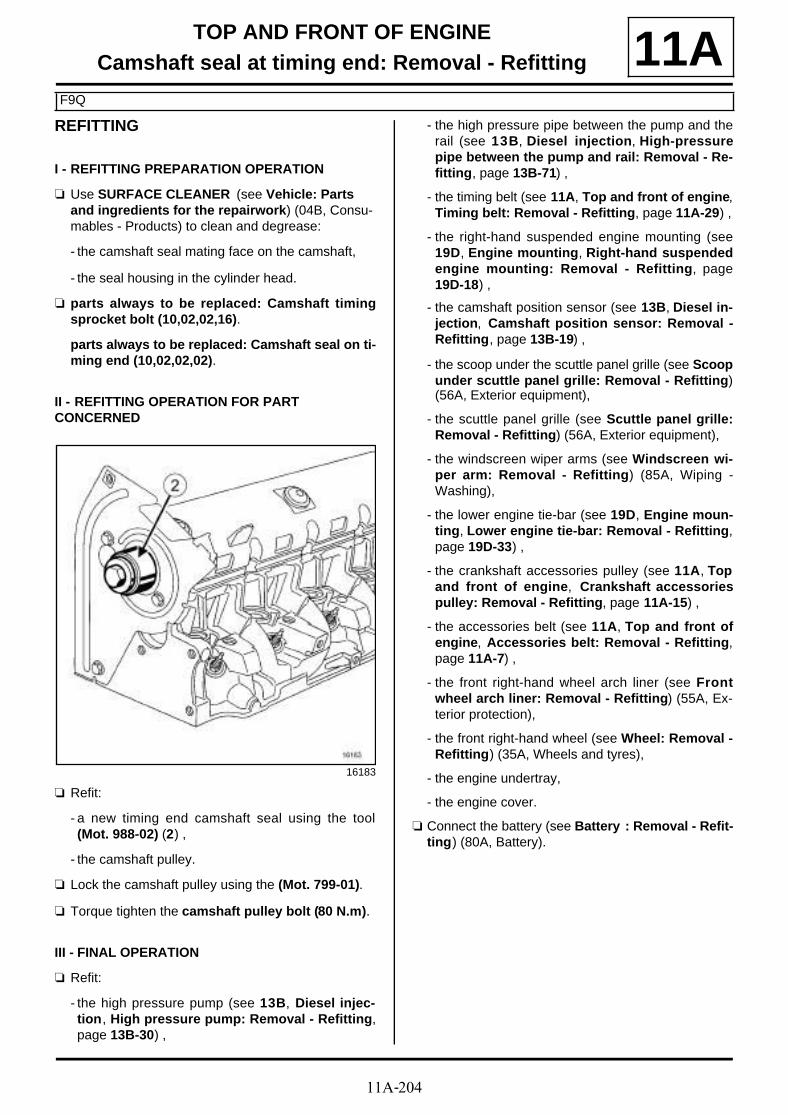
11A-204
TOP AND FRONT OF ENGINECamshaft seal at timing end: Removal - Refitting
F9Q
11AREFITTING
I - REFITTING PREPARATION OPERATION
a Use SURFACE CLEANER (see Vehicle: Parts and ingredients for the repairwork) (04B, Consu-mables - Products) to clean and degrease:
- the camshaft seal mating face on the camshaft,
- the seal housing in the cylinder head.
a parts always to be replaced: Camshaft timingsprocket bolt (10,02,02,16).
parts always to be replaced: Camshaft seal on ti-ming end (10,02,02,02).
II - REFITTING OPERATION FOR PART CONCERNED
a Refit:
- a new timing end camshaft seal using the tool(Mot. 988-02) (2) ,
- the camshaft pulley.
a Lock the camshaft pulley using the (Mot. 799-01).
a Torque tighten the camshaft pulley bolt (80 N.m).
III - FINAL OPERATION
a Refit:
- the high pressure pump (see 13B, Diesel injec-tion, High pressure pump: Removal - Refitting,page 13B-30) ,
- the high pressure pipe between the pump and therail (see 13B, Diesel injection, High-pressurepipe between the pump and rail: Removal - Re-fitting, page 13B-71) ,
- the timing belt (see 11A, Top and front of engine,Timing belt: Removal - Refitting, page 11A-29) ,
- the right-hand suspended engine mounting (see19D, Engine mounting, Right-hand suspendedengine mounting: Removal - Refitting, page19D-18) ,
- the camshaft position sensor (see 13B, Diesel in-jection, Camshaft position sensor: Removal -Refitting, page 13B-19) ,
- the scoop under the scuttle panel grille (see Scoopunder scuttle panel grille: Removal - Refitting)(56A, Exterior equipment),
- the scuttle panel grille (see Scuttle panel grille:Removal - Refitting) (56A, Exterior equipment),
- the windscreen wiper arms (see Windscreen wi-per arm: Removal - Refitting) (85A, Wiping -Washing),
- the lower engine tie-bar (see 19D, Engine moun-ting, Lower engine tie-bar: Removal - Refitting,page 19D-33) ,
- the crankshaft accessories pulley (see 11A, Topand front of engine, Crankshaft accessoriespulley: Removal - Refitting, page 11A-15) ,
- the accessories belt (see 11A, Top and front ofengine, Accessories belt: Removal - Refitting,page 11A-7) ,
- the front right-hand wheel arch liner (see Frontwheel arch liner: Removal - Refitting) (55A, Ex-terior protection),
- the front right-hand wheel (see Wheel: Removal -Refitting) (35A, Wheels and tyres),
- the engine undertray,
- the engine cover.
a Connect the battery (see Battery : Removal - Refit-ting) (80A, Battery).
16183
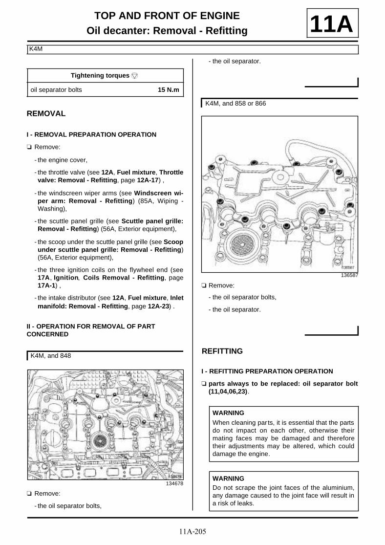
11A-205
TOP AND FRONT OF ENGINEOil decanter: Removal - Refitting
K4M
11A
REMOVAL
I - REMOVAL PREPARATION OPERATION
a Remove:
- the engine cover,
- the throttle valve (see 12A, Fuel mixture, Throttlevalve: Removal - Refitting, page 12A-17) ,
- the windscreen wiper arms (see Windscreen wi-per arm: Removal - Refitting) (85A, Wiping -Washing),
- the scuttle panel grille (see Scuttle panel grille:Removal - Refitting) (56A, Exterior equipment),
- the scoop under the scuttle panel grille (see Scoopunder scuttle panel grille: Removal - Refitting)(56A, Exterior equipment),
- the three ignition coils on the flywheel end (see17A, Ignition, Coils Removal - Refitting, page17A-1) ,
- the intake distributor (see 12A, Fuel mixture, Inletmanifold: Removal - Refitting, page 12A-23) .
II - OPERATION FOR REMOVAL OF PART CONCERNED
a Remove:
- the oil separator bolts,
- the oil separator.
a Remove:
- the oil separator bolts,
- the oil separator.
REFITTING
I - REFITTING PREPARATION OPERATION
a parts always to be replaced: oil separator bolt(11,04,06,23).
Tightening torquesm
oil separator bolts 15 N.m
K4M, and 848
134678
K4M, and 858 or 866
136587
WARNING
When cleaning par ts, it is essential that the partsdo not impact on each other, otherwise theirmating faces may be damaged and thereforetheir adjustments may be altered, which coulddamage the engine.
WARNINGDo not scrape the joint faces of the aluminium,any damage caused to the joint face will result ina risk of leaks.

11A-206
TOP AND FRONT OF ENGINEOil decanter: Removal - Refitting
K4M
11Aa Use SUPER CLEANING AGENT FOR JOINT FA-
CES (see Vehicle: Parts and ingredients for the repairwork) (04B, Consumables - Products) to clean:
- the joint face on the oil separator if it is to be re-used,
- the joint face on the rocker cover.
a Use SURFACE CLEANER (see Vehicle: Parts and ingredients for the repairwork) (04B, Consu-mables - Products) to degrease:
- the joint face on the oil separator if it is to be re-used,
- the joint face on the rocker cover.
a Apply RESIN ADHESIVE (see Vehicle: Parts andingredients for the repairwork) (04B, Consuma-bles - Products) using a stipple roller on the jointface of the oil separator until the joint face is comple-tely coated.
II - REFITTING OPERATION FOR PART CONCERNED
a Refit:
- the oil separator,
- new bolts on the oil separator.
a Refit:
- the oil separator,
WARNING
To ensure proper sealing, the gasket surfacesmust be clean, dry and not greasy (avoid any fin-ger marks).
WARNING
Applying excess sealant could cause it to besqueezed out when parts are tightened. A mix-ture of sealant and fluid could damage certaincomponents (engine, radiator, etc.).
102738
K4M, and 848
134678
K4M, and 858 or 866
136587

11A-207
TOP AND FRONT OF ENGINEOil decanter: Removal - Refitting
K4M
11A- new bolts on the oil separator.
a Torque tighten in order the oil separator bolts (15N.m).
III - FINAL OPERATION
a Refit:
- the inlet manifold (see 12A, Fuel mixture, Inletmanifold: Removal - Refitting, page 12A-23) ,
- the three ignition coils on the flywheel end (see17A, Ignition, Coils Removal - Refitting, page17A-1) ,
- the scoop under the scuttle panel grille (see Scoopunder scuttle panel grille: Removal - Refitting)(56A, Exterior equipment),
- the scuttle panel grille (see Scuttle panel grille:Removal - Refitting) (56A, Exterior equipment),
- the windscreen wiper arms (see Windscreen wi-per arm: Removal - Refitting) (85A, Wiping -Washing),
- the throttle valve (see 12A, Fuel mixture, Throttlevalve: Removal - Refitting, page 12A-17) ,
- the engine cover.

11A-208
TOP AND FRONT OF ENGINEOil decanter: Removal - Refitting
F9Q
11A
REMOVAL
I - REMOVAL PREPARATION OPERATION
a Position the vehicle on a two-post lift (see Vehicle:Towing and lifting) (02A, Lifting equipment).
a Remove:
- the engine cover,
- the engine undertray bolts,
- the engine undertray.
II - OPERATION FOR REMOVAL OF PART CONCERNED
a Remove the dipstick (1) .
a Disconnect the oil vapour rebreathing pipe (2) .a Disconnect the oil return pipes (3) .
a Remove the oil separator bolts (4) .
a Separate the oil separator clip on the cylinder blockusing the tool (Mot. 1448).
a Remove the oil separator.
Essential special tooling
Mot. 1448 Long nose pliers for hoseclips.
Tightening torquesm
oil separator bolts 30 N.m
133990
137191
137192

11A-209
TOP AND FRONT OF ENGINEOil decanter: Removal - Refitting
F9Q
11AREFITTING
I - REFITTING OPERATION FOR PART CONCERNED
a Refit the oil separator.
a Fit the oil separator clip on the cylinder block usingthe tool (Mot. 1448).
a Refit the oil separator bolts.
a Torque tighten the oil separator bolts (30 N.m).
a Connect:
- the oil return pipes,
- the oil vapour rebreathing pipe.
a Refit the dipstick.
II - FINAL OPERATION
a Refit:
- the engine undertray,
- the engine cover.

11A-210
TOP AND FRONT OF ENGINEOil decanter: Removal - Refitting
F4R
11A
REMOVAL
I - REMOVAL PREPARATION OPERATION
a Position the vehicle on a two-post lift (see Vehicle:Towing and lifting) (02A, Lifting equipment).
a Remove:
- the engine undertray bolts,
- the engine undertray,
- the engine cover.
a Disconnect the battery (see Battery: Removal - Re-fitting) (80A, Battery).
a Remove:
- the windscreen wiper arms (see Windscreen wi-per arm: Removal - Refitting) (85A, Wiping -Washing),
- the scuttle panel grille (see Scuttle panel grille:Removal - Refitting) (56A, Exterior equipment),
- the scoop under the scuttle panel grille (see Scoopunder scuttle panel grille: Removal - Refitting)(56A, Exterior equipment).
a Remove:
- the bolts (1) of the turbocharger bracket,
- the turbocharger bracket.
Tightening torquesm
oil separator bolts 12 N.m
IMPORTANT
Wear leaktight gloves (Nitrile type) for this opera-tion.
134635

11A-211
TOP AND FRONT OF ENGINEOil decanter: Removal - Refitting
F4R
11A
a Disconnect the oil vapour rebreathing pipe at (2) .
a Remove the oil vapour rebreathing pipe.
a Remove:
- the upstream oxygen sensor (see 17B, Petrol in-jection, Oxygen sensors: Removal - Refitting,page 17B-1) ,
- the front right-hand wheel (see Wheel: Removal -Refitting) (35A, Wheels and tyres),
- the front section of the front right-hand wheel archliner (see Front wheel arch liner: Removal - Re-fitting) (55A, Exterior protection).
a Drain the manual gearbox (see Manual gearboxoil: Draining - Refilling) (21A, Manual gearbox).
a Remove:
- the front right-hand wheel driveshaft (see Front ri-ght-hand wheel driveshaft: Removal - Refitting)(29A, Driveshafts),
- the right-hand differential output seal (see Diffe-rential output seal: Removal - Refitting) (21A,Manual gearbox),
- the lower engine tie-bar (see 19D, Engine moun-ting, Lower engine tie-bar: Removal - Refitting,page 19D-33) ,
- the connecting hose (see 19B, Exhaust, Connec-ting hose: Removal - Refitting, page 19B-60) ,
- the catalytic converter (see 19B, Exhaust, Cataly-tic converter: Removal - Refitting, page 19B-17),
- the turbocharger oil pipes (see 12B, Turbochar-ging, Turbocharger oil pipe: Removal - Refit-ting, page 12B-22) ,
- the turbocharger (see 12B, Turbocharging, Tur-bocharger: Removal - Refitting, page 12B-8) .
II - OPERATION FOR REMOVAL OF PART CONCERNED
a Remove:
- the oil decanter bolts,
- the oil separator.
135778
135779
120209
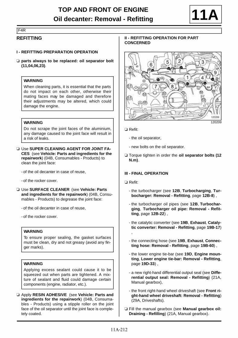
11A-212
TOP AND FRONT OF ENGINEOil decanter: Removal - Refitting
F4R
11AREFITTING
I - REFITTING PREPARATION OPERATION
a parts always to be replaced: oil separator bolt(11,04,06,23).
a Use SUPER CLEANING AGENT FOR JOINT FA-CES (see Vehicle: Parts and ingredients for the repairwork) (04B, Consumables - Products) to clean the joint face:
- of the oil decanter in case of reuse,
- of the rocker cover.
a Use SURFACE CLEANER (see Vehicle: Parts and ingredients for the repairwork) (04B, Consu-mables - Products) to degrease the joint face:
- of the oil decanter in case of reuse,
- of the rocker cover.
a Apply RESIN ADHESIVE (see Vehicle: Parts andingredients for the repairwork) (04B, Consuma-bles - Products) using a stipple roller on the jointface of the oil separator until the joint face is comple-tely coated.
II - REFITTING OPERATION FOR PART CONCERNED
a Refit:
- the oil separator,
- new bolts on the oil separator.
a Torque tighten in order the oil separator bolts (12N.m).
III - FINAL OPERATION
a Refit:
- the turbocharger (see 12B, Turbocharging, Tur-bocharger: Removal - Refitting, page 12B-8) ,
- the turbocharger oil pipes (see 12B, Turbochar-ging, Turbocharger oil pipe: Removal - Refit-ting, page 12B-22) ,
- the catalytic converter (see 19B, Exhaust, Cataly-tic converter: Removal - Refitting, page 19B-17),
- the connecting hose (see 19B, Exhaust, Connec-ting hose: Removal - Refitting, page 19B-60) ,
- the lower engine tie-bar (see 19D, Engine moun-ting, Lower engine tie-bar: Removal - Refitting,page 19D-33) ,
- a new right-hand differential output seal (see Diffe-rential output seal: Removal - Refitting) (21A,Manual gearbox),
- the front right-hand wheel driveshaft (see Front ri-ght-hand wheel driveshaft: Removal - Refitting)(29A, Driveshafts).
a Fill the manual gearbox (see Manual gearbox oil:Draining - Refilling) (21A, Manual gearbox).
WARNING
When cleaning parts, it is essential that the partsdo not impact on each other, otherwise theirmating faces may be damaged and thereforetheir adjustments may be altered, which coulddamage the engine.
WARNING
Do not scrape the joint faces of the aluminium,any damage caused to the joint face will result ina risk of leaks.
WARNING
To ensure proper sealing, the gasket surfacesmust be clean, dry and not greasy (avoid any fin-ger marks).
WARNING
Applying excess sealant could cause it to besqueezed out when parts are tightened. A mix-ture of sealant and fluid could damage certaincomponents (engine, radiator, etc.).
120209

11A-213
TOP AND FRONT OF ENGINEOil decanter: Removal - Refitting
F4R
11Aa Refit:
- the front section of the front right-hand wheel archliner (see Front wheel arch liner: Removal - Re-fitting) (55A, Exterior protection),
- the front right-hand wheel (see Wheel: Removal -Refitting) (35A, Wheels and tyres),
- the upstream oxygen sensor (see 17B, Petrol in-jection, Oxygen sensors: Removal - Refitting,page 17B-1) ,
- the oil vapour rebreathing pipe,
- the turbocharger bracket,
- the scoop under the scuttle panel grille (see Scoopunder scuttle panel grille: Removal - Refitting)(56A, Exterior equipment),
- the scuttle panel grille (see Scuttle panel grille:Removal - Refitting) (56A, Exterior equipment),
- the windscreen wiper arms (see Windscreen wi-per arm: Removal - Refitting) (85A, Wiping -Washing),
a Connect the battery (see Battery: Removal - Refit-ting) (80A, Battery).
a Refit:
- the engine cover,
- the engine undertray.

12A-1
FUEL MIXTUREAir resonator: Removal - Refitting 12A
REMOVAL
I - REMOVAL PREPARATION OPERATION
a Position the vehicle on a two-post lift (see Vehicle:Towing and lifting) (02A, Lifting equipment).
a Remove:
- the front wheels (see Wheel: Removal - Refitting)(35A, Wheels and tyres),
- the front section of the front wheel arch liners (seeFront wheel arch liner: Removal - Refitting)(55A, Exterior protection),
- the front bumper (see Front bumper: Removal -Refitting) (55A, Exterior protection),
- the left-hand headlight (see Front headlight: Re-moval - Refitting) (80B, Headlights),
- the front left-hand support of the front bumper (seeFront bumper support: Removal - Refitting)(42A, Front upper structure).
II - OPERATION FOR REMOVAL OF PART CONCERNED
a Remove:
- the air resonator bolts (1) ,
- the air resonator.
REFITTING
I - REFITTING OPERATION FOR PART CONCERNED
a Refit the air resonator.
II - FINAL OPERATION
a Refit:
- the front left-hand support of the front bumper (seeFront bumper support: Removal - Refitting)(42A, Front upper structure),
- the left-hand headlight (see Front headlight: Re-moval - Refitting) (80B, Headlights),
- the front bumper (see Front bumper: Removal -Refitting) (55A, Exterior protection),
- the front section of the front wheel arch liners (seeFront wheel arch liner: Removal - Refitting)(55A, Exterior protection),
- the front wheels (see Wheel: Removal - Refitting)(35A, Wheels and tyres).
136956

12A-2
FUEL MIXTUREAir filter: Removal - Refitting 12A
REMOVAL
I - REMOVAL PREPARATION OPERATION
a Remove the battery cover.
a Move aside the wiring (1) .
II - OPERATION FOR REMOVAL OF PART CONCERNED
a Undo the bolts (2) from the air filter unit slide valve.
a Pull the air filter unit slide valve upwards at (3) .
a Remove the air filter (4) .
REFITTING
I - REFITTING PREPARATION OPERATION
a Clean the air filter housing.
138705
134240
134239
134237

12A-3
FUEL MIXTUREAir filter: Removal - Refitting 12A
II - REFITTING OPERATION
a
a Refit:
- the air filter,
- the air filter unit slide valve,
- the air filter unit slide valve bolts.
III - FINAL OPERATION
a Fit the wiring.
a Refit the battery cover.
WARNING
If the air filter is fitted incorrectly in the air filterunit, unfiltered air may enter the engine.

12A-4
FUEL MIXTUREAir filter unit: Removal - Refitting 12A
REMOVAL
I - REMOVAL PREPARATION OPERATION
a Remove the battery (see Battery : Removal - Refit-ting) (80A, Battery).
a Remove the battery tray (see Battery tray: Remo-val - Refitting) (80A, Battery).
Tightening torquesm
air filter unit bolts 8 N.m
air filter unit air outletpipe clip
6 N.m

12A-5
FUEL MIXTUREAir filter unit: Removal - Refitting 12A
II - OPERATION FOR REMOVAL OF PART CONCERNED
a Undo the clip (1) of the air filter unit air outlet pipe.
a Disconnect the air outlet pipe from the air filter unit.
a Move the air outlet pipe of the air filter unit to one si-de.
a Disconnect the air flowmeter connector (2) .
a Unclip the connector (3) from the scuttle panel grille.
a Loosen the clip (4) of the air outlet pipe on the air fil-ter unit.
a Move the air outlet pipe of the air filter unit to one si-de.
III - OPERATION FOR REMOVAL OF PART CONCERNED
a Remove:
- the air filter unit bolt (5) ,
F9Q or K9K
134038
134039
F4R or K4M
135707
134073

12A-6
FUEL MIXTUREAir filter unit: Removal - Refitting 12A
- the « air filter unit - air filter - air sleeve » assembly(6) ,
- the air sleeve of the « air filter unit - air filter - airsleeve » assembly.
If replacing the air filter unit
a Remove the air flowmeter (see 12A, Fuel mixture,Air flowmeter: Removal - Refitting, page 12A-7) .
REFITTING
I - REFITTING PREPARATION OPERATION
a Refit the air flowmeter (see 12A, Fuel mixture, Airflowmeter: Removal - Refitting, page 12A-7) .
II - REFITTING OPERATION FOR PART CONCERNED
a Refit:
- the air sleeve to the « air filter unit - air filter - airsleeve » assembly,
- the « air filter unit - air filter - air sleeve » assembly,
- the air filter unit bolts.
a Torque tighten the air filter unit bolts (8 N.m).
a Connect the air flowmeter connector.
a Clip the connector onto the scuttle panel grille.
a Connect the air outlet pipe of the air filter unit.
a Torque tighten the air filter unit air outlet pipe clip(6 N.m).
a Refit the battery tray (see Battery tray: Removal -Refitting) (80A, Battery).
a Refit the battery (see Battery: Removal - Refitting)(80A, Battery).
F9Q or K9K
F9Q or K9K
F9Q or K9K

12A-7
FUEL MIXTUREAir flowmeter: Removal - Refitting
K9K
12A
REMOVAL
I - REMOVAL PREPARATION OPERATION
a Remove the front engine cover.
a Loosen the clip (1) of the air filter unit air outlet pipeon the air flowmeter.
a Disconnect the air filter unit air outlet pipe from theair flowmeter.
a Move the air filter unit air outlet pipe slightly awayfrom the air flowmeter.
II - OPERATION FOR REMOVAL OF PART CONCERNED
a Disconnect the air flowmeter connector (2) .
a Remove:
- the bolts (3) from the air flowmeter,
- the air flowmeter (4) ,
- the air flowmeter seal.
Essential equipment
diagnostic tool
Tightening torquesm
air filter box air outletpipe clip on the air flow-meter
5.5 N.m
134044
134044
134041

12A-8
FUEL MIXTUREAir flowmeter: Removal - Refitting
K9K
12AREFITTING
I - REFITTING PREPARATION OPERATION
a parts always to be replaced: Air flowmeter seal(11,04,06,26).
II - REFITTING OPERATION FOR PART CONCERNED
a Refit the air flowmeter, fitted with a new seal.
a Connect the air flowmeter connector.
III - FINAL OPERATION
a Fit the air filter unit air outlet pipe.
a Connect the air filter box air outlet pipe to the airflowmeter.
a Torque tighten the air filter box air outlet pipe clipon the air flowmeter (5.5 N.m).
a Apply the after repair procedure using the diagnos-tic tool :
- connect the diagnostic tool,
- Select "Injection computer",
- go to repair mode,
- display the "After repair procedure" for the compu-ter selected,
- select "Air flowmeter" in the "List of componentsstored by this computer" section,
- carry out the operations described in the "After re-pair procedure" section.
K9K, and 834

12A-9
FUEL MIXTUREAir flowmeter: Removal - Refitting
F9Q
12A
REMOVAL
I - REMOVAL PREPARATION OPERATION
a Remove:
- the engine cover,
- the windscreen wiper arms (see Windscreen wi-per arm: Removal - Refitting) (85A, Wiping -Washing),
- the scuttle panel grille (see Scuttle panel grille:Removal - Refitting) (56A, Exterior equipment),
- the scoop under the scuttle panel grille (see Scoopunder scuttle panel grille: Removal - Refitting)(56A, Exterior equipment).
II - OPERATION FOR REMOVAL OF PART CONCERNED
a Loosen the clip (1) of the air outlet pipe on the air fil-ter unit.
a Disconnect the air outlet pipe from the air filter unit.
a Disconnect the air flowmeter connector (2) .
a Remove:
- the bolts (3) from the air flowmeter,
- the air flowmeter (4) .
- the air flowmeter seal.
REFITTING
I - REFITTING PREPARATION OPERATION
a parts always to be replaced: Air flowmeter seal(11,04,06,26).
II - REFITTING OPERATION FOR PART CONCERNED
a Refit:
- a new seal on the air flowmeter,
- the air flowmeter.
a Torque tighten the air flowmeter (4 N.m).
a Connect the air outlet pipe of the air filter unit.
a Connect the air flowmeter connector.
III - FINAL OPERATION
a Refit:
- the scoop under the scuttle panel grille (see Scoopunder scuttle panel grille: Removal - Refitting)(56A, Exterior equipment),
- the scuttle panel grille (see Scuttle panel grille:Removal - Refitting) (56A, Exterior equipment),
Essential equipment
diagnostic tool
Tightening torquesm
air flowmeter 4 N.m
133989
114993
12A-10
FUEL MIXTUREAir flowmeter: Removal - Refitting
F9Q
12A- the windscreen wiper arms (see Windscreen wi-per arm: Removal - Refitting) (85A, Wiping -Washing),
- the engine cover.
a Apply the after repair procedure using the diagnos-tic tool :
- connect the diagnostic tool,
- select « Injection computer » ,
- go to repair mode,
- display the « before/after repair procedure » for thecomputer selected,
- select « Air flowmeter » in the « List of componentsstored by this computer » section,
- carry out the operations described in the « After re-pair procedure » section.
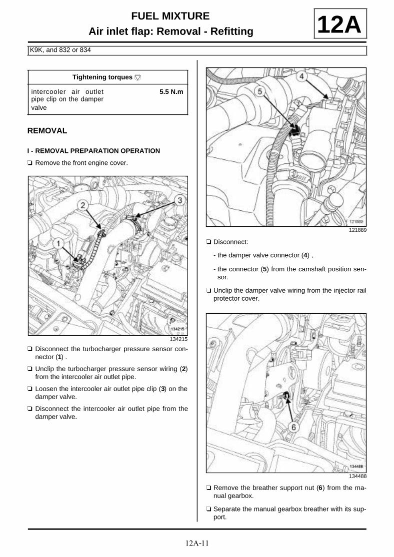
12A-11
FUEL MIXTUREAir inlet flap: Removal - Refitting
K9K, and 832 or 834
12A
REMOVAL
I - REMOVAL PREPARATION OPERATION
a Remove the front engine cover.
a Disconnect the turbocharger pressure sensor con-nector (1) .
a Unclip the turbocharger pressure sensor wiring (2)from the intercooler air outlet pipe.
a Loosen the intercooler air outlet pipe clip (3) on thedamper valve.
a Disconnect the intercooler air outlet pipe from thedamper valve.
a Disconnect:
- the damper valve connector (4) ,
- the connector (5) from the camshaft position sen-sor.
a Unclip the damper valve wiring from the injector railprotector cover.
a Remove the breather support nut (6) from the ma-nual gearbox.
a Separate the manual gearbox breather with its sup-port.
Tightening torquesm
intercooler air outletpipe clip on the dampervalve
5.5 N.m
134215
121889
134488

12A-12
FUEL MIXTUREAir inlet flap: Removal - Refitting
K9K, and 832 or 834
12A
a Disconnect the brake servo pipe union (7) from thevacuum pump.
II - OPERATION FOR REMOVAL OF PART CONCERNED
a Remove:
- the damper valve bracket bolts (8) ,
- the damper valve bracket.
a Remove:
- the damper valve bolts (9) ,
- the damper valve,
- the damper valve seal.
REFITTING
I - REFITTING PREPARATION OPERATION
a parts always to be replaced: Damper valve seal(11,01,10,04).
a Use SURFACE CLEANER (see Vehicle: Parts and ingredients for the repairwork) (04B, Consu-mables - Products) to clean and degrease the joint faces:
- of the exhaust gas recirculation support on theflywheel end,
- the damper valve if it is to be reused.
II - REFITTING OPERATION FOR PART CONCERNED
a Refit:
- a new damper valve seal,
- the damper valve,
- the damper valve bracket.
134490
134491
135464

12A-13
FUEL MIXTUREAir inlet flap: Removal - Refitting
K9K, and 832 or 834
12AIII - FINAL OPERATION
a Connect the brake servo pipe union to the vacuumpump.
a Fit the manual gearbox breather to its support.
a Refit the gearbox breather mounting nut.
a Clip the damper valve wiring onto the injector railprotector cover.
a Connect:
- the camshaft position sensor connector,
- the damper valve connector,
- the intercooler outlet air pipe on the damper valve.
a Torque tighten the intercooler air outlet pipe clipon the damper valve (5.5 N.m).
a Clip the turbocharger pressure sensor wiring ontothe intercooler air outlet pipe.
a Connect the turbocharger pressure sensor connec-tor.
a Refit the engine cover.
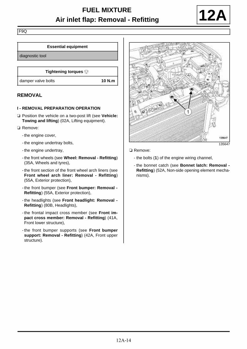
12A-14
FUEL MIXTUREAir inlet flap: Removal - Refitting
F9Q
12A
REMOVAL
I - REMOVAL PREPARATION OPERATION
a Position the vehicle on a two-post lift (see Vehicle:Towing and lifting) (02A, Lifting equipment).
a Remove:
- the engine cover,
- the engine undertray bolts,
- the engine undertray,
- the front wheels (see Wheel: Removal - Refitting)(35A, Wheels and tyres),
- the front section of the front wheel arch liners (seeFront wheel arch liner: Removal - Refitting)(55A, Exterior protection),
- the front bumper (see Front bumper: Removal -Refitting) (55A, Exterior protection),
- the headlights (see Front headlight: Removal -Refitting) (80B, Headlights),
- the frontal impact cross member (see Front im-pact cross member: Removal - Refitting) (41A,Front lower structure),
- the front bumper supports (see Front bumpersupport: Removal - Refitting) (42A, Front upperstructure).
a Remove:
- the bolts (1) of the engine wiring channel,
- the bonnet catch (see Bonnet latch: Removal -Refitting) (52A, Non-side opening element mecha-nisms).
Essential equipment
diagnostic tool
Tightening torquesm
damper valve bolts 10 N.m
135647

12A-15
FUEL MIXTUREAir inlet flap: Removal - Refitting
F9Q
12A
a Remove the front end panel bolts (2) .
a Tilt the front end panel.
a Remove intercooler air outlet pipe (see 12B, Turbo-charging, Intercooler air outlet pipe: Removal -Refitting, page 12B-56) .
II - OPERATION FOR REMOVAL OF PART CONCERNED
a Disconnect the connector (3) from the damper valve.
a Remove:
- the damper valve bolts (4) ,
- the damper valve,
- the damper valve seal.
135645
135646
136193
136195

12A-16
FUEL MIXTUREAir inlet flap: Removal - Refitting
F9Q
12AREFITTING
I - REFITTING PREPARATION OPERATION
a Use SURFACE CLEANER (see Vehicle: Parts and ingredients for the repairwork) (04B, Consu-mables - Products) to clean and degrease:
- the bearing face of the damper valve in case of reu-se,
- the bearing face of the air inlet pipe of the inlet ma-nifold.
a parts always to be replaced: Damper valve seal(11,01,10,04).
II - REFITTING OPERATION FOR PART CONCERNED
a Refit:
- a new seal to the damper valve,
- the damper valve.
a Torque tighten the damper valve bolts (10 N.m).
a Connect the damper valve connector.
III - FINAL OPERATION
a Refit:
- a new intercooler air outlet pipe (see 12B, Turbo-charging, Intercooler air outlet pipe: Removal -Refitting, page 12B-56)
- the front end panel,
- the bonnet catch (see Bonnet latch: Removal -Refitting) (52A, Non-side opening element mecha-nisms),
- the bolts of the engine wiring channel.
- the front bumper supports (see Front bumpersupport: Removal - Refitting) (42A, Front upperstructure),
- the front impact cross member (see Front impactcross member: Removal - Refitting) (41A, Frontlower structure),
- the headlights (see Front headlight: Removal -Refitting) (80B, Headlights),
- the front bumper (see Front bumper: Removal -Refitting) (55A, Exterior protection),
- the front section of the front wheel arch liners (seeFront wheel arch liner: Removal - Refitting)(55A, Exterior protection),
- the front wheels (see Wheel: Removal - Refitting)(35A, Wheels and tyres),
- the engine undertray,
- the engine cover.
a Apply the after repair procedure using the diagnos-tic tool :
- connect the diagnostic tool,
- select « Injection computer » ,
- go to repair mode,
- display the « before/after repair procedure » for thecomputer selected,
- select « Damper valve » in the « List of compo-nents stored by this computer » section,
- carry out the operations described in the « After re-pair procedure » section.
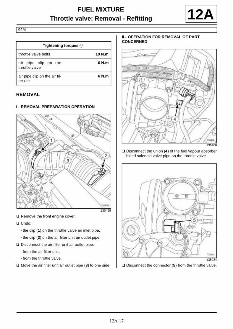
12A-17
FUEL MIXTUREThrottle valve: Removal - Refitting
K4M
12A
REMOVAL
I - REMOVAL PREPARATION OPERATION
a Remove the front engine cover.
a Undo:
- the clip (1) on the throttle valve air inlet pipe,
- the clip (2) on the air filter unit air outlet pipe.
a Disconnect the air filter unit air outlet pipe:
- from the air filter unit,
- from the throttle valve.
a Move the air filter unit air outlet pipe (3) to one side.
II - OPERATION FOR REMOVAL OF PART CONCERNED
a Disconnect the union (4) of the fuel vapour absorberbleed solenoid valve pipe on the throttle valve.
a Disconnect the connector (5) from the throttle valve.
Tightening torquesm
throttle valve bolts 10 N.m
air pipe clip on thethrottle valve
6 N.m
air pipe clip on the air fil-ter unit
6 N.m
136458
136460
135924

12A-18
FUEL MIXTUREThrottle valve: Removal - Refitting
K4M
12A
a Remove:
- the throttle valve bolts (6) ,
- the throttle valve.
a Remove the throttle valve seal.
REFITTING
I - REFITTING PREPARATION OPERATION
a parts always to be replaced: Throttle valve seal(11,04,06,25).
a Use SURFACE CLEANER (see Vehicle: Parts and ingredients for the repairwork) (04B, Consu-mables - Products) to clean and degrease:
- the inlet manifold joint face if reused,
- the seal housing on the inlet manifold.
II - REFITTING OPERATION FOR PART CONCERNED
a Refit:
- a new seal on the inlet manifold,
- the throttle valve.
a In order, torque tighten the throttle valve bolts (10N.m).
III - FINAL OPERATION
a Connect to the throttle valve:
- the union of the fuel vapour absorber bleed sole-noid valve pipe on the throttle valve,
- the throttle valve connector.
a Fit the air filter unit air outlet pipe.
a Connect the air filter unit air outlet pipe:
- to air filter unit,
- to the throttle valve.
a Tighten to torque:
- the air pipe clip on the throttle valve (6 N.m),
- the air pipe clip on the air filter unit (6 N.m).
a Refit the engine cover.
135923
WARNING
To ensure proper sealing, the joint faces must beclean, dry and not greasy (avoid any fingermarks).
WARNINGDo not scrape the joint faces of the aluminium,any damage caused to the joint face will result ina risk of leaks.
135923

12A-19
FUEL MIXTUREThrottle valve: Removal - Refitting
F4R
12A
REMOVAL
a Remove the front engine cover.
a Remove the bolts (1) on the intercooler outlet air pi-pe.
a Move the intercooler outlet air pipe to one side.
OPERATION FOR REMOVAL OF PART CONCERNED
a Disconnect the connector (2) from the throttle valve.
a Remove:
- the throttle valve bolts (3) ,
- the throttle valve,
- the throttle valve seal.
Tightening torquesm
throttle valve bolts 10 N.m
135796
135782
135782
12A-20
FUEL MIXTUREThrottle valve: Removal - Refitting
F4R
12AREFITTING
I - REFITTING PREPARATION OPERATION
a parts always to be replaced: Throttle valve seal(11,04,06,25).
II - REFITTING OPERATION FOR PART CONCERNED
a Refit:
- a new seal on the throttle valve,
- the throttle valve,
- the throttle valve bolts.
a Torque tighten the throttle valve bolts (10 N.m).
a Connect the throttle valve connector.
III - FINAL OPERATION
a Fit the intercooler air outlet pipe.
a Refit:
- the intercooler air outlet pipe bolts,
- the engine cover.
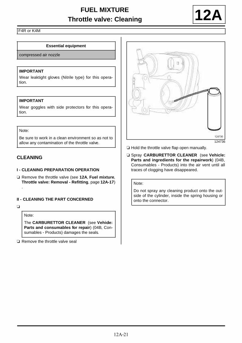
12A-21
FUEL MIXTUREThrottle valve: Cleaning
F4R or K4M
12A
CLEANING
I - CLEANING PREPARATION OPERATION
a Remove the throttle valve (see 12A, Fuel mixture,Throttle valve: Removal - Refitting, page 12A-17).
II - CLEANING THE PART CONCERNED
a
a Remove the throttle valve seal
a Hold the throttle valve flap open manually.
a Spray CARBURETTOR CLEANER (see Vehicle:Parts and ingredients for the repairwork) (04B,Consumables - Products) into the air vent until alltraces of clogging have disappeared.
Essential equipment
compressed air nozzle
IMPORTANT
Wear leaktight gloves (Nitrile type) for this opera-tion.
IMPORTANT
Wear goggles with side protectors for this opera-tion.
Note:
Be sure to work in a clean environment so as not toallow any contamination of the throttle valve.
Note:
The CARBURETTOR CLEANER (see Vehicle:Parts and consumables for repair) (04B, Con-sumables - Products) damages the seals.
124736
Note:
Do not spray any cleaning product onto the out-side of the cylinder, inside the spring housing oronto the connector.
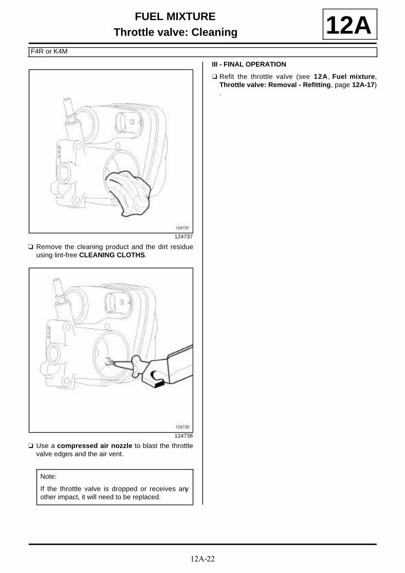
12A-22
FUEL MIXTUREThrottle valve: Cleaning
F4R or K4M
12A
a Remove the cleaning product and the dirt residueusing lint-free CLEANING CLOTHS.
a Use a compressed air nozzle to blast the throttlevalve edges and the air vent.
III - FINAL OPERATION
a Refit the throttle valve (see 12A, Fuel mixture,Throttle valve: Removal - Refitting, page 12A-17).
124737
124738
Note:
If the throttle valve is dropped or receives anyother impact, it will need to be replaced.

12A-23
FUEL MIXTUREInlet manifold: Removal - Refitting
K4M
12A
REMOVAL
I - REMOVAL PREPARATION OPERATION
a Remove:
- the engine cover,
- the windscreen wiper arms (see Windscreen wi-per arm: Removal - Refitting) (85A, Wiping -Washing),
- the scuttle panel grille (see Scuttle panel grille:Removal - Refitting) (56A, Exterior equipment),
- the scoop under the scuttle panel grille (see Scoopunder scuttle panel grille: Removal - Refitting)(56A, Exterior equipment),
- the throttle valve (see 12A, Fuel mixture, Throttlevalve: Removal - Refitting, page 12A-17) .
a Disconnect:
- all coil connectors (1) ,
- the air temperature sensor connector (2) .
a Unclip the wiring from the inlet manifold coils.
a Move the coil wiring to one side.
a Disconnect the following from the inlet manifold:
- the inlet manifold pressure sensor connector (3) ,
- the oil vapour rebreathing hose (4) .
Tightening torquesm
bolts 1 to 5 of the inletmanifold
9 N.m
bolts 6 to 8 of the inletmanifold
12 N.m
IMPORTANT
During this operation, be sure to:
- refrain from smoking or bringing red hot objectsclose to the working area,
- be careful of fuel splashes when disconnecting theunion.
IMPORTANT
Wear leaktight gloves (Nitrile type) for this opera-tion.
WARNING
To avoid any corrosion or damage, protect theareas on which fuel is likely to run.
WARNING
To prevent impurities from entering the circuit, placeprotective plugs on all fuel circuit componentsexposed to the open air.
136482
136548

12A-24
FUEL MIXTUREInlet manifold: Removal - Refitting
K4M
12A
a Disconnect the brake servo pipe union (5) from theinlet manifold.
a Unclip the following from the inlet manifold:
- the engine wiring (6) ,
- the fuel vapour absorber bleed solenoid valve pipe.
a Disconnect the connector (7) from the camshaft de-phaser solenoid valve.
a Unclip the camshaft dephaser solenoid valve wiringfrom the inlet manifold.
136460
136548
K4M, and 858 or 866
136579

12A-25
FUEL MIXTUREInlet manifold: Removal - Refitting
K4M
12AII - OPERATION FOR REMOVAL OF PART CONCERNED
a Remove:
- the inlet manifold bolts (8) ,
- the inlet manifold,
- the inlet manifold seals.
REFITTING
I - REFITTING PREPARATION OPERATION
a parts always to be replaced: Intake distributorseal (10,07,01,07).
a Use SURFACE CLEANER (see Vehicle: Partsand ingredients for the repairwork) (04B, Consu-mables - Products) to clean and degrease:
- the housing of each inlet manifold seal,
- the seal face of the injector holder shim.
a Fit new seals to the inlet manifold.
a When replacing the inlet manifold, remove:
- the air temperature sensor,
- the inlet manifold pressure sensor.
II - REFITTING OPERATION FOR PART CONCERNED
a Refit the inlet manifold.
a Tighten to torque and in order:
- bolts 1 to 5 of the inlet manifold (9 N.m),
- bolts 6 to 8 of the inlet manifold (12 N.m).
III - FINAL OPERATION
a Clip the camshaft dephaser solenoid valve wiringonto the inlet manifold.
a Connect the camshaft dephaser solenoid valve con-nector.
a Connect the following to the inlet manifold:
- the brake servo pipe union,
- the oil vapour rebreathing hose,
- the inlet manifold pressure sensor connector.
a Clip the following onto the inlet manifold:
- the engine wiring,
- the fuel vapour absorber bleed solenoid valve pipe.
a Fit the coil wiring.
a Clip the coil wiring onto the inlet manifold.
136482 136482
K4M, and 858 or 866

12A-26
FUEL MIXTUREInlet manifold: Removal - Refitting
K4M
12Aa Connect:
- the connector of each coil,
- the air temperature sensor connector.
a Refit:
- the throttle valve (see 12A, Fuel mixture, Throttlevalve: Removal - Refitting, page 12A-17) ,
- the scoop under the scuttle panel grille (see Scoopunder scuttle panel grille: Removal - Refitting)(56A, Exterior equipment),
- the scuttle panel grille (see Scuttle panel grille:Removal - Refitting) (56A, Exterior equipment),
- the windscreen wiper arms (see Windscreen wi-per arm: Removal - Refitting) (85A, Wiping -Washing),
- the engine cover.
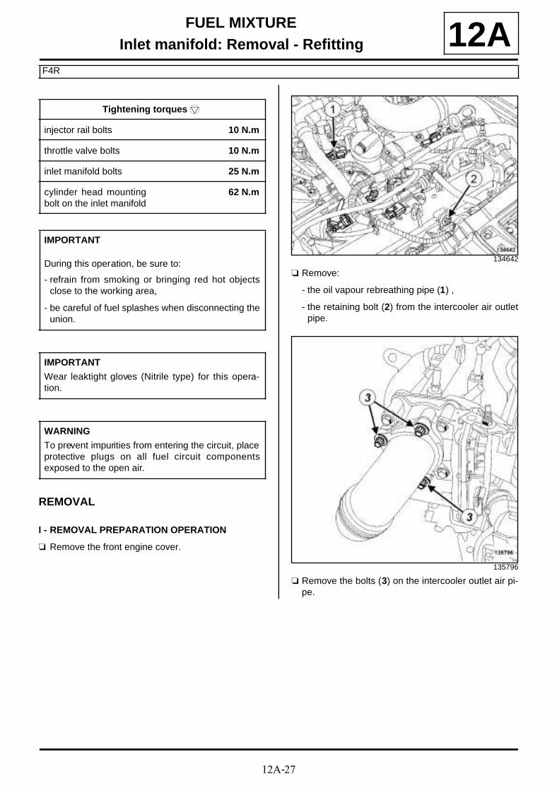
12A-27
FUEL MIXTUREInlet manifold: Removal - Refitting
F4R
12A
REMOVAL
I - REMOVAL PREPARATION OPERATION
a Remove the front engine cover.
a Remove:
- the oil vapour rebreathing pipe (1) ,
- the retaining bolt (2) from the intercooler air outletpipe.
a Remove the bolts (3) on the intercooler outlet air pi-pe.
Tightening torquesm
injector rail bolts 10 N.m
throttle valve bolts 10 N.m
inlet manifold bolts 25 N.m
cylinder head mountingbolt on the inlet manifold
62 N.m
IMPORTANT
During this operation, be sure to:
- refrain from smoking or bringing red hot objectsclose to the working area,
- be careful of fuel splashes when disconnecting theunion.
IMPORTANT
Wear leaktight gloves (Nitrile type) for this opera-tion.
WARNING
To prevent impurities from entering the circuit, placeprotective plugs on all fuel circuit componentsexposed to the open air.
134642
135796
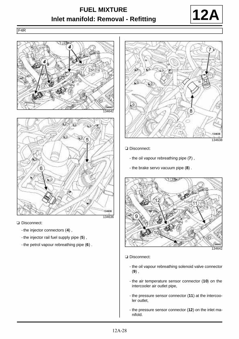
12A-28
FUEL MIXTUREInlet manifold: Removal - Refitting
F4R
12A
a Disconnect:
- the injector connectors (4) ,
- the injector rail fuel supply pipe (5) ,
- the petrol vapour rebreathing pipe (6) .
a Disconnect:
- the oil vapour rebreathing pipe (7) ,
- the brake servo vacuum pipe (8) .
a Disconnect:
- the oil vapour rebreathing solenoid valve connector(9) ,
- the air temperature sensor connector (10) on theintercooler air outlet pipe,
- the pressure sensor connector (11) at the intercoo-ler outlet,
- the pressure sensor connector (12) on the inlet ma-nifold.
134642
134636
134638
134642
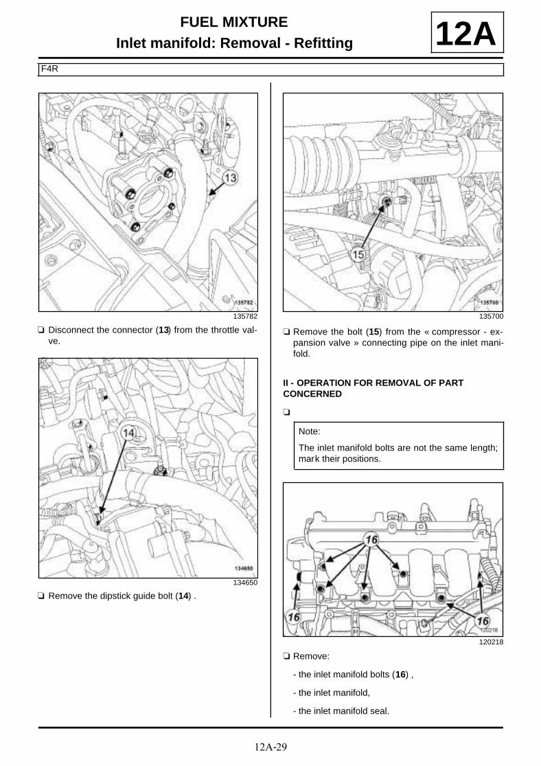
12A-29
FUEL MIXTUREInlet manifold: Removal - Refitting
F4R
12A
a Disconnect the connector (13) from the throttle val-ve.
a Remove the dipstick guide bolt (14) .
a Remove the bolt (15) from the « compressor - ex-pansion valve » connecting pipe on the inlet mani-fold.
II - OPERATION FOR REMOVAL OF PART CONCERNED
a
a Remove:
- the inlet manifold bolts (16) ,
- the inlet manifold,
- the inlet manifold seal.
135782
134650
135700
Note:
The inlet manifold bolts are not the same length;mark their positions.
120218

12A-30
FUEL MIXTUREInlet manifold: Removal - Refitting
F4R
12AREFITTING
I - REFITTING PREPARATION OPERATION
a parts always to be replaced: Intake distributorseal (10,07,01,07)
a Use SURFACE CLEANER (see Vehicle: Parts and ingredients for the repairwork) (04B, Consu-mables - Products) to clean and degrease:
- the cylinder head joint face,
- the inlet manifold joint face if reused.
When replacing the inlet manifold
a Remove:
- the throttle valve bolts,
- the throttle valve,
- the throttle valve seal,
- the oil vapour heater bolt,
- the oil vapour heater,
- the oil vapour heater seals,
- the air inlet pressure sensor clip,
- the air inlet pressure sensor,
- the injector rail bolts,
- the injector rail,
- the injector seals.
a Always replace:
- the injector seals,
- the oil vapour heater seals,
- the throttle valve seal.
a Refit:
- new seals on the injectors,
- the injector rail on the new inlet manifold,
- the injector rail bolts.
a Torque tighten the injector rail bolts (10 N.m).
a Refit:
- the air inlet pressure sensor,
- the air inlet pressure sensor clip,
- new seals on the oil vapour heater,
- the oil vapour heater,
- a new seal on the throttle valve,
- the throttle valve.
a Torque tighten the throttle valve bolts (10 N.m).
II - OPERATION FOR REFITTING PART CONCERNED
a Refit:
- a new seal on the inlet manifold,
- the inlet manifold.
a Fit without tightening:
- the inlet manifold bolts,
- the cylinder head mounting bolt on the inlet mani-fold.
a Tighten to torque:
- the inlet manifold bolts (25 N.m),
- the cylinder head mounting bolt on the inlet ma-nifold (62 N.m).
III - FINAL OPERATION
a Refit:
- the bolt from the « compressor - expansion valve »connecting pipe on the inlet manifold,
- the dipstick guide bolt,
- the bolt for the intercooler air outlet pipe.
a Connect:
- the throttle valve connector,
- the pressure sensor connector on the inlet mani-fold,
- the pressure sensor connector at the intercooleroutlet,
- the air temperature sensor connector on the inter-cooler air outlet pipe,
- the oil vapour rebreathing solenoid valve connec-tor,
- the brake servo vacuum pipe,
- the oil vapour rebreathing pipe,
- the petrol vapour rebreathing pipe,
- the fuel supply pipe from the injector rail,
- the injector connectors.
a Refit:
- the intercooler air outlet pipe bolts,
- the retaining bolt of the intercooler air outlet pipe onthe inlet manifold,
- the engine cover.

12A-31
FUEL MIXTUREInjector holder shim: Removal - Refitting
K4M
12A
REMOVAL
I - REMOVAL PREPARATION OPERATION
a Position the vehicle on a two-post lift (see Vehicle:Towing and lifting) (02A, Lifting equipment).
a Disconnect the battery (see Battery: Removal - Re-fitting) (80A, Battery).
a Remove:
- the engine cover,
- the front right-hand wheel (see Wheel: Removal -Refitting) (35A, Wheels and tyres),
- the front section of the front right-hand wheel archliner (see Front wheel arch liner: Removal - Re-fitting) (55A, Exterior protection),
- the windscreen wiper arms (see Windscreen wi-per arm: Removal - Refitting) (85A, Wiping -Washing),
- the scuttle panel grille (see Scuttle panel grille:Removal - Refitting) (56A, Exterior equipment),
- the scoop under the scuttle panel grille (see Scoopunder scuttle panel grille: Removal - Refitting)(56A, Exterior equipment),
- the accessories belt (see 11A, Top and front ofengine, Accessories belt: Removal - Refitting,page 11A-7) .
a Remove:
- the dipstick,
- the bolts (1) from the dipstick tube,
- the dipstick guide.
a Remove:
- the throttle valve (see 12A, Fuel mixture, Throttlevalve: Removal - Refitting, page 12A-17) ,
- the inlet manifold (see 12A, Fuel mixture, Inletmanifold: Removal - Refitting, page 12A-23) ,
- the « injector rail - injector » assembly (see 17B,Petrol injection, Injector rail - Injectors: Remo-val - Refitting, page 17B-19) .
Tightening torquesm
bolts 1 and 2 on theinjector holder shim
30 N.m
bolts 3, 4, 5, 6, 7, 8, 9and 10 on the injectorholder shim
25 N.m
upper timing cover bolt 46 N.m
right-hand pendulumsuspension bolt
62 Nm
dipstick guide tube bolts 10 N.m
K4M, and 858 or 866
136574

12A-32
FUEL MIXTUREInjector holder shim: Removal - Refitting
K4M
12AII - OPERATION FOR REMOVAL OF PART CONCERNED
a Remove:
- the bolt (2) from the upper timing cover,
- the right-hand pendulum suspension bolt (3) ,
- the injector holder shim bolts,
- the injector holder shim,
- the injector holder shim seal.
REFITTING
I - REFITTING PREPARATION OPERATION
a parts always to be replaced: Inlet shim seal (11,04,04,09).
a Use SURFACE CLEANER (see Vehicle: Parts and ingredients for the repairwork) (04B, Consu-mables - Products) to clean and degrease:
- the cylinder head joint face,
- the gasket face of the injector holder shim, in caseof reuse.
II - REFITTING OPERATION FOR PART CONCERNED
a Refit:
- a new seal on the injector holder shim,
- the injector holder shim.
a Fit without tightening the bolts on the injector holdershim.
a Tighten to torque and in order:
- bolts 1 and 2 on the injector holder shim (30N.m),
- bolts 3, 4, 5, 6, 7, 8, 9 and 10 on the injector hol-der shim (25 N.m).
a Tighten to torque:
- the upper timing cover bolt (46 N.m),
- the right-hand pendulum suspension bolt (62Nm).
136491
135261
WARNING
To ensure proper sealing, the gasket surfacesmust be clean, dry and not greasy (avoid any fin-ger marks).
WARNING
Do not scrape the joint faces of the aluminium,any damage caused to the joint face will result ina risk of leaks.
135261
12A-33
FUEL MIXTUREInjector holder shim: Removal - Refitting
K4M
12AIII - FINAL OPERATION
a Refit:
- the « injector rail - injector » assembly (see 17B,Petrol injection, Injector rail - Injectors: Remo-val - Refitting, page 17B-19) ,
- the inlet manifold (see 12A, Fuel mixture, Inletmanifold: Removal - Refitting, page 12A-23) ,
- the throttle valve (see 12A, Fuel mixture, Throttlevalve: Removal - Refitting, page 12A-17) .
a Refit the dipstick guide.
a Torque tighten the dipstick guide tube bolts (10N.m).
a Refit the dipstick.
a Refit:
- the accessories belt (see 11A, Top and front ofengine, Accessories belt: Removal - Refitting,page 11A-7) ,
- the scoop under the scuttle panel grille (see Scoopunder scuttle panel grille: Removal - Refitting)(56A, Exterior equipment),
- the scuttle panel grille (see Scuttle panel grille:Removal - Refitting) (56A, Exterior equipment),
- the windscreen wiper arms (see Windscreen wi-per arm: Removal - Refitting) (85A, Wiping -Washing),
- the front section of the front right-hand wheel archliner (see Front wheel arch liner: Removal - Re-fitting) (55A, Exterior protection),
- the front right-hand wheel (see Wheel: Removal -Refitting) (35A, Wheels and tyres),
- the engine cover.
a Connect the battery (see Battery: Removal - Refit-ting) (80A, Battery).
K4M, and 858 or 866

12A-34
FUEL MIXTUREExhaust manifold - Intake distributor: Removal - Refitting
F9Q
12A
REMOVAL
I - REMOVAL PREPARATION OPERATION
a Position the vehicle on a two-post lift (see Vehicle:Towing and lifting) (02A, Lifting equipment).
a Remove:
- the engine cover,
- the engine undertray bolts,
- the engine undertray,
- the battery (see Battery : Removal - Refitting)(80A, Battery),
- the battery tray (see Battery tray: Removal - Re-fitting) (80A, Battery),
- the windscreen wiper arms (see Windscreen wi-per arm: Removal - Refitting) (85A, Wiping -Washing),
- the scuttle panel grille (see Scuttle panel grille:Removal - Refitting) (56A, Exterior equipment),
- the scoop under the scuttle panel grille (see Scoopunder scuttle panel grille: Removal - Refitting)(56A, Exterior equipment),
- the intercooler air inlet pipe (see 12B, Turbochar-ging, Intercooler air inlet pipe: Removal - Refit-ting, page 12B-41) ,
- the turbocharger outlet exhaust gas duct (see 12B,Turbocharging, Turbocharger outlet exhaustgas duct: Removal - Refitting, page 12B-49) ,
- the exhaust gas recirculation assembly (see 14A,Antipollution, Exhaust gas recirculation as-sembly: Removal - Refitting, page 14A-18) ,
- the lower engine tie-bar (see 19D, Engine moun-ting, Lower engine tie-bar: Removal - Refitting,page 19D-33) ,
- the turbocharger (see 12B, Turbocharging, Tur-bocharger: Removal - Refitting, page 12B-8) .
a Remove the bolts (1) from the inlet manifold air inletpipe.
a Remove:
- the bolts (2) from the turbocharger control solenoidvalve,
- the turbocharger control solenoid valve,
- the bolts (3) from the exhaust manifold heat shield,
- the exhaust manifold heat shield.
Tightening torquesm
exhaust manifold - inletmanifold nuts
33 N.m
bolts on the right-handlifting eye
25 N.m
inlet manifold air inletpipe bolts
25 N.m
137475
137476

12A-35
FUEL MIXTUREExhaust manifold - Intake distributor: Removal - Refitting
F9Q
12A
a Remove:
- the bolts (4) from the lifting eye on the right-hand si-de,
- the lifting eye on the right-hand side.
II - OPERATION FOR REMOVAL OF PART CONCERNED
a Remove:
- the "exhaust manifold - inlet manifold" nuts,
- the "exhaust manifold - inlet manifold",
- the seal on the "exhaust manifold - inlet manifold".
137477
137481
137480
12A-36
FUEL MIXTUREExhaust manifold - Intake distributor: Removal - Refitting
F9Q
12AREFITTING
I - REFITTING PREPARATION OPERATION
a parts always to be replaced: exhaust gas recir-culation pipe bolt (11,07,01,18),
parts always to be replaced: Exhaust manifoldnut (10,07,02,08),
parts always to be replaced: intake distributorstud on cylinder head (if loosened) (10,07,01,08),
a Always replace the seal of the "exhaust manifold -inlet manifold".
II - REFITTING OPERATION FOR PART CONCERNED
a Apply some FRENETANCHE to the top of the cylin-der head thread holes.
a Wipe any run-off after refitting the studs.
a Refit:
- a new seal on the exhaust manifold - inlet manifold,
- the exhaust manifold - inlet manifold.
a Torque tighten the exhaust manifold - inlet mani-fold nuts (33 N.m).
III - FINAL OPERATION
a Refit the lifting eye on the right-hand side.
a Torque tighten the bolts on the right-hand liftingeye (25 N.m).
a Refit:
- the exhaust manifold heat shield,
- the turbocharger control solenoid valve,
- the bolts on the inlet manifold air inlet pipe.
a Torque tighten the inlet manifold air inlet pipebolts (25 N.m).
a Refit:
- the turbocharger (see 12B, Turbocharging, Tur-bocharger: Removal - Refitting, page 12B-8) ,
- the lower engine tie-bar (see 19D, Engine moun-ting, Lower engine tie-bar: Removal - Refitting,page 19D-33) ,
- the exhaust gas recirculation assembly (see 14A,Antipollution, Exhaust gas recirculation as-sembly: Removal - Refitting, page 14A-18) ,
- the turbocharger outlet exhaust gas duct (see 12B,Turbocharging, Turbocharger outlet exhaustgas duct: Removal - Refitting, page 12B-49) ,
- the intercooler air inlet pipe (see 12B, Turbochar-ging, Intercooler air inlet pipe: Removal - Refit-ting, page 12B-41) ,
- the scoop under the scuttle panel grille (see Scoopunder scuttle panel grille: Removal - Refitting)(56A, Exterior equipment),
- the scuttle panel grille (see Scuttle panel grille:Removal - Refitting) (56A, Exterior equipment),
- the windscreen wiper arms (see Windscreen wi-per arm: Removal - Refitting) (85A, Wiping -Washing),
- the battery tray (see Battery tray: Removal - Re-fitting) (80A, Battery),
- the battery (see Battery : Removal - Refitting)(80A, Battery),
- the engine undertray,
- the engine cover.
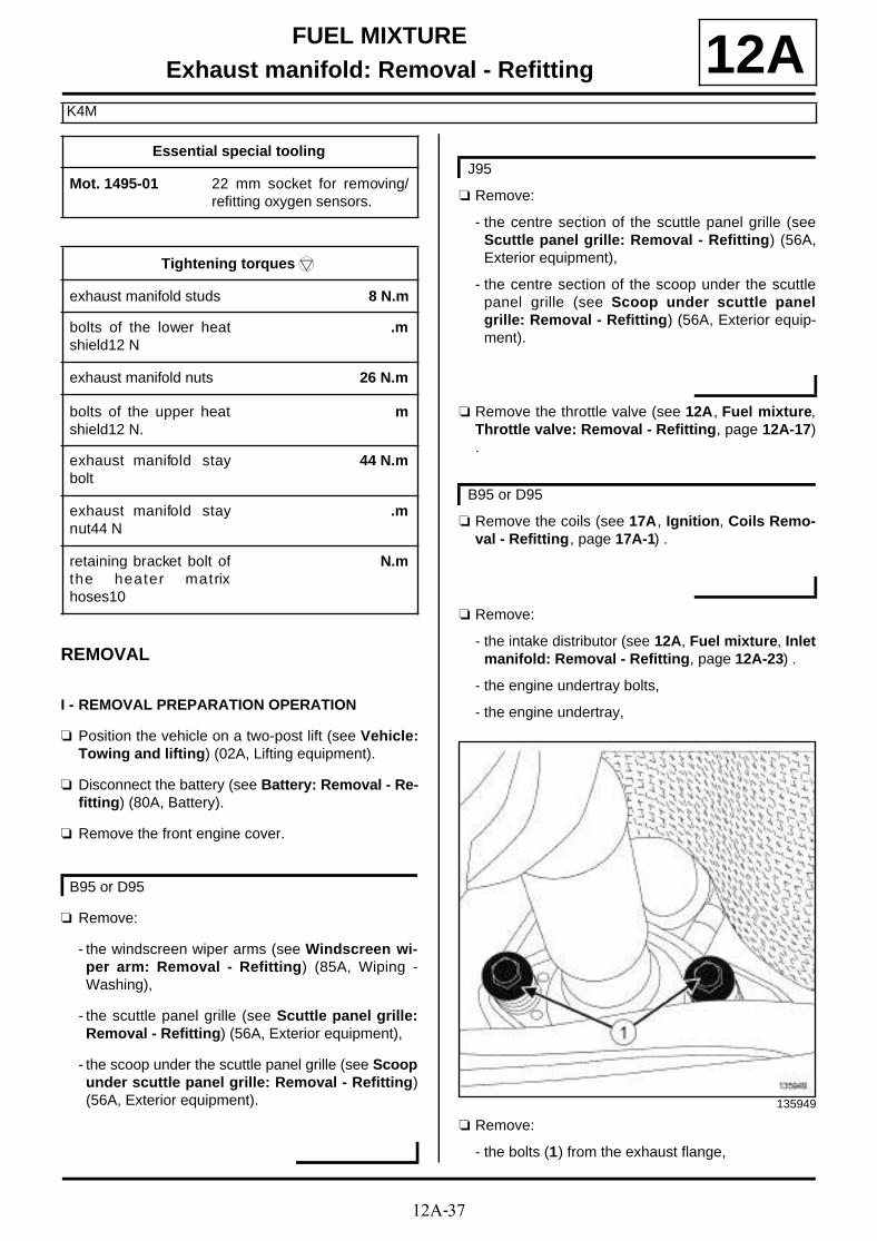
12A-37
FUEL MIXTUREExhaust manifold: Removal - Refitting
K4M
12A
REMOVAL
I - REMOVAL PREPARATION OPERATION
a Position the vehicle on a two-post lift (see Vehicle:Towing and lifting) (02A, Lifting equipment).
a Disconnect the battery (see Battery: Removal - Re-fitting) (80A, Battery).
a Remove the front engine cover.
a Remove:
- the windscreen wiper arms (see Windscreen wi-per arm: Removal - Refitting) (85A, Wiping -Washing),
- the scuttle panel grille (see Scuttle panel grille:Removal - Refitting) (56A, Exterior equipment),
- the scoop under the scuttle panel grille (see Scoopunder scuttle panel grille: Removal - Refitting)(56A, Exterior equipment).
a Remove:
- the centre section of the scuttle panel grille (seeScuttle panel grille: Removal - Refitting) (56A,Exterior equipment),
- the centre section of the scoop under the scuttlepanel grille (see Scoop under scuttle panelgrille: Removal - Refitting) (56A, Exterior equip-ment).
a Remove the throttle valve (see 12A, Fuel mixture,Throttle valve: Removal - Refitting, page 12A-17).
a Remove the coils (see 17A, Ignition, Coils Remo-val - Refitting, page 17A-1) .
a Remove:
- the intake distributor (see 12A, Fuel mixture, Inletmanifold: Removal - Refitting, page 12A-23) .
- the engine undertray bolts,
- the engine undertray,
a Remove:
- the bolts (1) from the exhaust flange,
Essential special tooling
Mot. 1495-01 22 mm socket for removing/refitting oxygen sensors.
Tightening torquesm
exhaust manifold studs 8 N.m
bolts of the lower heatshield12 N
.m
exhaust manifold nuts 26 N.m
bolts of the upper heatshield12 N.
m
exhaust manifold staybolt
44 N.m
exhaust manifold staynut44 N
.m
retaining bracket bolt ofthe heater matrixhoses10
N.m
B95 or D95
J95
B95 or D95
135949

12A-38
FUEL MIXTUREExhaust manifold: Removal - Refitting
K4M
12A- the ring between the exhaust manifold and the ca-talytic converter.
a Remove:
- the nut (2) from the exhaust manifold stay,
- the bolt (3) from the exhaust manifold stay,
- the exhaust manifold strut.
a Disconnect the upstream oxygen sensor connector(4) .
a Unclip the heater matrix hoses from the retainingbracket (5) .
a Remove:
- the heater matrix hose retaining bracket bolt,
- the heater matrix hose retaining bracket.
a Remove:
- the bolts (6) from the upper heat shield,
- the upper heat shield.
136514
136546
135927
135255

12A-39
FUEL MIXTUREExhaust manifold: Removal - Refitting
K4M
12AII - OPERATION FOR REMOVAL OF PART CONCERNED
a Remove:
- the exhaust manifold nuts,
- the exhaust manifold,
- the exhaust manifold gasket.
When replacing the exhaust manifold
a Remove:
- the lower heat shield bolts (7) ,
- the lower heat shield,
- the upstream oxygen sensor using the (Mot. 1495-01).
REFITTING
I - REFITTING PREPARATION OPERATION
a parts always to be replaced: Exhaust manifoldseal (10,07,02,07).
a parts always to be replaced: ring between ex-haust manifold and catalytic converter (10,08,02,20).
a Use SURFACE CLEANER (see Vehicle: Parts and ingredients for the repairwork) (04B, Consu-mables - Products) to clean and degrease:
- the exhaust manifold joint face if it is to be re-used,
- the cylinder head joint face.
a Tighten to torque the exhaust manifold studs (8N.m).
135711
135911
109399
Note:
If a stud loosens during removal, coat it withHIGH RESISTANCE THREADLOCK (see Vehi-cle: Parts and ingredients for the repairwork)(04B, Consumables - Products).

12A-40
FUEL MIXTUREExhaust manifold: Removal - Refitting
K4M
12A
a Refit the upstream oxygen sensor using the tool(Mot. 1495-01).
a Refit the lower heat shield.
a Screw on the bolts (4) and (5) without tightening.
a Tighten in order and to torque the bolts of the lowerheat shield12 N (.m).
II - REFITTING OPERATION FOR PART CONCERNED
a Refit:
- a new exhaust manifold seal,
- the exhaust manifold.
a Torque tighten in order the exhaust manifold nuts(26 N.m).
III - FINAL OPERATION
a Refit the upper heat shield.
135911
135711

12A-41
FUEL MIXTUREExhaust manifold: Removal - Refitting
K4M
12A
a Screw on the bolts (4) and (5) without tightening.
a Tighten in order and to torque the bolts of the up-per heat shield12 N. (m).
a Refit the exhaust manifold stay.
a Tighten to torque:
- the exhaust manifold stay bolt (44 N.m),
- the exhaust manifold stay nut44 N (.m).
a Refit:
- a new ring between the exhaust manifold and thecatalytic converter,
- the exhaust bracket bolts,
- the heater matrix hose retaining bracket.
a Torque tighten the retaining bracket bolt of theheater matrix hoses10 (N.m).
a Clip the hoses onto the retaining bracket of the hea-ter matrix hoses.
a Connect the upstream oxygen sensor connector.
a Refit:
- the engine undertray,
- the intake distributor (see 12A, Fuel mixture, Inletmanifold: Removal - Refitting, page 12A-23) .
a Refit the coils (see 17A, Ignition, Coils Removal -Refitting, page 17A-1) .
a Refit the throttle valve (see 12A, Fuel mixture,Throttle valve: Removal - Refitting, page 12A-17).
a Refit:
- the scoop under the scuttle panel grille (see Scoopunder scuttle panel grille: Removal - Refitting)(56A, Exterior equipment).
- the scuttle panel grille (see Scuttle panel grille:Removal - Refitting) (56A, Exterior equipment),
- the windscreen wiper arms (see Windscreen wi-per arm: Removal - Refitting) (85A, Wiping -Washing).
a Refit:
- the centre section of the scoop under the scuttlepanel grille (see Scoop under scuttle panelgrille: Removal - Refitting) (56A, Exterior equip-ment),
- the centre section of the scuttle panel grille (seeScuttle panel grille: Removal - Refitting) (56A,Exterior equipment).
a Refit the engine cover.
a Connect the battery (see Battery: Removal - Refit-ting) (80A, Battery).
135255
B95 or D95
B95 or D95
J95

12A-42
FUEL MIXTUREExhaust manifold: Removal - Refitting
K9K, and 830 or 832
12A
REMOVAL
I - REMOVAL PREPARATION OPERATION
a Position the vehicle on a two-post lift (see Vehicle:Towing and lifting) (02A, Lifting equipment).
a Disconnect the battery (see Battery : Removal -Refitting) (80A, Battery).
a Remove:
- the centre section of the scuttle panel grille (seeScuttle panel grille: Removal - Refitting) ,
- the centre section of the scoop under the scuttlepanel grille (see Scoop under scuttle panelgrille: Removal - Refitting) .
a Remove:
- the engine cover,
- the engine undertray bolts,
- the engine undertray,
a Remove the lower engine tie-bar (see 19D, Enginemounting, Lower engine tie-bar: Removal - Refit-ting, page 19D-33) .
a Remove:
- the catalytic converter (see 19B, Exhaust, Cataly-tic converter: Removal - Refitting, page 19B-17),
- the turbocharger air outlet pipe (see 12B, Turbo-charging, Intercooler air inlet pipe: Removal -Refitting, page 12B-41) ,
- the turbocharger oil supply pipe (see 12B, Turbo-charging, Turbocharger oil pipe: Removal - Re-fitting, page 12B-22) ,
- the turbocharger oil return pipe (see 12B, Turbo-charging, Turbocharger oil pipe: Removal - Re-fitting, page 12B-22) ,
- the turbocharger (see 12B, Turbocharging, Tur-bocharger: Removal - Refitting, page 12B-8) .
a Remove:
- the bolts (1) from the lifting eye at the timing end,
- the lifting eye on the timing end,
- the rigid exhaust gas recirculation pipe (see 14A,Antipollution, Exhaust gas recirculation rigidpipe: Removal - Refitting, page 14A-30) .
Tightening torquesm
exhaust manifold nuts 26 N.m
IMPORTANT
Wear protective gloves during the operation.
J95
K9K, and 830
135463

12A-43
FUEL MIXTUREExhaust manifold: Removal - Refitting
K9K, and 830 or 832
12AII - OPERATION FOR REMOVAL OF PART CONCERNED
a Remove:
- the nuts (2) from the exhaust manifold,
- the exhaust manifold.
a Mark the position of the exhaust manifold gasket.
a Remove the exhaust manifold gasket.
REFITTING
I - REFITTING PREPARATION OPERATION
a parts always to be replaced: Exhaust manifoldseal (10,07,02,07).
a Use ABRASIVE PADS to clean the joint face:
- the cylinder head,
- of the exhaust manifold, if it is to be reused.
a Use SURFACE CLEANER (see Vehicle: Parts and ingredients for the repairwork) (04B, Consu-mables - Products) and CLEAN CLOTHS to clean and degrease the joint faces:
- the cylinder head,
- of the exhaust manifold, if it is to be reused.
II - REFITTING OPERATION FOR PART CONCERNED
a Refit:
- a new exhaust manifold gasket in the position mar-ked during removal,
- the exhaust manifold.
a Torque tighten in order the exhaust manifold nuts(26 N.m).
III - FINAL OPERATION
a Refit:
- the exhaust gas recirculation rigid pipe (see 14A,Antipollution, Exhaust gas recirculation rigidpipe: Removal - Refitting, page 14A-30) ,
- the lifting eye on the timing end,
- the turbocharger (see 12B, Turbocharging, Tur-bocharger: Removal - Refitting, page 12B-8) .
- the turbocharger oil return pipe (see 12B, Turbo-charging, Turbocharger oil pipe: Removal - Re-fitting, page 12B-22) ,
- the turbocharger oil supply pipe (see 12B, Turbo-charging, Turbocharger oil pipe: Removal - Re-fitting, page 12B-22) ,
- the turbocharger air outlet pipe (see 12B, Turbo-charging, Intercooler air inlet pipe: Removal -Refitting, page 12B-41) ,
- the catalytic converter (see 19B, Exhaust, Cataly-tic converter: Removal - Refitting, page 19B-17).
113561114532

12A-44
FUEL MIXTUREExhaust manifold: Removal - Refitting
K9K, and 830 or 832
12A
a Refit the lower engine tie-bar (see 19D, Enginemounting, Lower engine tie-bar: Removal - Refit-ting, page 19D-33) .
a Refit:
- the engine undertray,
- the engine cover.
a Refit:
- the centre section of the scoop under the scuttlepanel grille (see Scoop under scuttle panelgrille: Removal - Refitting) ,
- the centre section of the scuttle panel grille (seeScuttle panel grille: Removal - Refitting) .
a Connect the battery (see Battery : Removal - Refit-ting) (80A, Battery).
K9K, and 830
J95
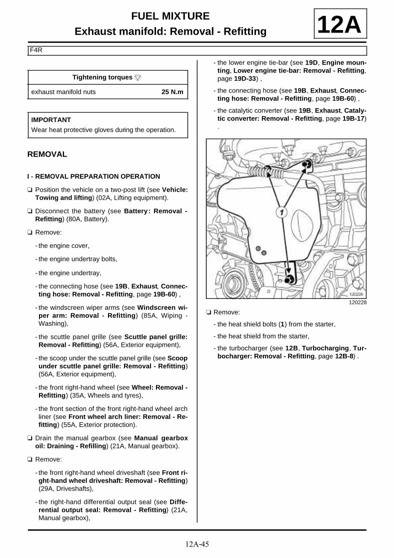
12A-45
FUEL MIXTUREExhaust manifold: Removal - Refitting
F4R
12A
REMOVAL
I - REMOVAL PREPARATION OPERATION
a Position the vehicle on a two-post lift (see Vehicle:Towing and lifting) (02A, Lifting equipment).
a Disconnect the battery (see Battery : Removal -Refitting) (80A, Battery).
a Remove:
- the engine cover,
- the engine undertray bolts,
- the engine undertray,
- the connecting hose (see 19B, Exhaust, Connec-ting hose: Removal - Refitting, page 19B-60) ,
- the windscreen wiper arms (see Windscreen wi-per arm: Removal - Refitting) (85A, Wiping -Washing),
- the scuttle panel grille (see Scuttle panel grille:Removal - Refitting) (56A, Exterior equipment),
- the scoop under the scuttle panel grille (see Scoopunder scuttle panel grille: Removal - Refitting)(56A, Exterior equipment),
- the front right-hand wheel (see Wheel: Removal -Refitting) (35A, Wheels and tyres),
- the front section of the front right-hand wheel archliner (see Front wheel arch liner: Removal - Re-fitting) (55A, Exterior protection).
a Drain the manual gearbox (see Manual gearboxoil: Draining - Refilling) (21A, Manual gearbox).
a Remove:
- the front right-hand wheel driveshaft (see Front ri-ght-hand wheel driveshaft: Removal - Refitting)(29A, Driveshafts),
- the right-hand differential output seal (see Diffe-rential output seal: Removal - Refitting) (21A,Manual gearbox),
- the lower engine tie-bar (see 19D, Engine moun-ting, Lower engine tie-bar: Removal - Refitting,page 19D-33) ,
- the connecting hose (see 19B, Exhaust, Connec-ting hose: Removal - Refitting, page 19B-60) ,
- the catalytic converter (see 19B, Exhaust, Cataly-tic converter: Removal - Refitting, page 19B-17).
a Remove:
- the heat shield bolts (1) from the starter,
- the heat shield from the starter,
- the turbocharger (see 12B, Turbocharging, Tur-bocharger: Removal - Refitting, page 12B-8) .
Tightening torquesm
exhaust manifold nuts 25 N.m
IMPORTANT
Wear heat protective gloves during the operation.
120228

12A-46
FUEL MIXTUREExhaust manifold: Removal - Refitting
F4R
12AII - OPERATION FOR REMOVAL OF PART CONCERNED
a Remove:
- the nuts (2) from the exhaust manifold,
- the exhaust manifold,
- the exhaust manifold gasket.
REFITTING
I - REFITTING PREPARATION OPERATION
a parts always to be replaced: Exhaust manifoldseal (10,07,02,07).
a Use SURFACE CLEANER (see Vehicle: Parts and ingredients for the repairwork) (04B, Consu-mables - Products) to clean and degrease:
- the exhaust manifold joint face if it is to be re-used,
- the cylinder head joint face.
II - REFITTING OPERATION FOR PART CONCERNED
a Refit:
- a new exhaust manifold gasket,
- the exhaust manifold.
a Screw on the exhaust manifold nuts without tighte-ning them.
a Tighten to torque and in order the exhaust manifoldnuts (25 N.m).
III - FINAL OPERATION
a Refit:
- the heat shield to the starter,
- the catalytic converter (see 19B, Exhaust, Cataly-tic converter: Removal - Refitting, page 19B-17),
- the connecting hose (see 19B, Exhaust, Connec-ting hose: Removal - Refitting, page 19B-60) ,
- the lower engine tie-bar (see 19D, Engine moun-ting, Lower engine tie-bar: Removal - Refitting,page 19D-33) ,
- a new right-hand differential output seal (see Diffe-rential output seal: Removal - Refitting) (21A,Manual gearbox),
- the front right-hand wheel driveshaft (see Front ri-ght-hand wheel driveshaft: Removal - Refitting)(29A, Driveshafts).
a Fill the manual gearbox (see Manual gearbox oil:Draining - Refilling) (21A, Manual gearbox).
21936
Note:
If a stud loosens during this operation, coat itwith HIGH STRENGTH THREAD LOCK (seeVehicle: Parts and ingredients for the repai-rwork) (04B, Consumables - Products).
21936

12A-47
FUEL MIXTUREExhaust manifold: Removal - Refitting
F4R
12Aa Refit:
- the front section of the front right-hand wheel archliner (see Front wheel arch liner: Removal - Re-fitting) (55A, Exterior protection),
- the front right-hand wheel (see Wheel: Removal -Refitting) (35A, Wheels and tyres),
- the scoop under the scuttle panel grille (see Scoopunder scuttle panel grille: Removal - Refitting)(56A, Exterior equipment),
- the scuttle panel grille (see Scuttle panel grille:Removal - Refitting) (56A, Exterior equipment),
- the windscreen wiper arms (see Windscreen wi-per arm: Removal - Refitting) (85A, Wiping -Washing),
- the connecting hose (see 19B, Exhaust, Connec-ting hose: Removal - Refitting, page 19B-60) ,
- the engine undertray,
- the engine cover.
a Connect the battery (see Battery : Removal - Refit-ting) (80A, Battery).

12A-48
FUEL MIXTUREExhaust manifold: Removal - Refitting
K9K, and 836
12A
REMOVAL
I - REMOVAL PREPARATION OPERATION
a Position the vehicle on a two-post lift (see Vehicle:Towing and lifting) (02A, Lifting equipment).
a Remove:
- the engine cover,
- the engine undertray bolts,
- the engine undertray.
a Remove:
- the scuttle panel grille centre section (see Scuttlepanel grille: Removal - Refitting) ,
- the scoop under the centre section of the scuttlepanel grille (see Scoop under scuttle panelgrille: Removal - Refitting) .
a Remove:
- the exhaust gases duct at the turbocharger outlet(see 12B, Turbocharging, Turbocharger outletexhaust gas duct: Removal - Refitting, page12B-49) ,
- the turbocharger oil supply pipe (see 12B, Turbo-charging, Turbocharger oil pipe: Removal - Re-fitting, page 12B-22) ,
- the turbocharger oil return pipe (see 12B, Turbo-charging, Turbocharger oil pipe: Removal - Re-fitting, page 12B-22) ,
- the exhaust gas recirculation rigid pipe (see 14A,Antipollution, Exhaust gas recirculation rigidpipe: Removal - Refitting, page 14A-30) ,
- the exhaust gas recirculation assembly (see 14A,Antipollution, Exhaust gas recirculation as-sembly: Removal - Refitting, page 14A-18) ,
- the turbocharger (see 12B, Turbocharging, Tur-bocharger: Removal - Refitting, page 12B-8) ,
- the exhaust gas temperature sensor (see 19B, Ex-haust, Exhaust gas temperature sensor: Remo-val - Refitting, page 19B-50) .
II - OPERATION FOR REMOVAL OF PART CONCERNED
a Remove:
- the exhaust manifold nuts,
- the exhaust manifold,
- the exhaust manifold gasket.
REFITTING
I - REFITTING PREPARATION OPERATION
a parts always to be replaced: Exhaust manifoldseal (10,07,02,07)
a Use ABRASIVE PADS to clean the joint face:
- the cylinder head,
- of the exhaust manifold, if it is to be reused.
a Use SURFACE CLEANER (see Vehicle: Parts and consumables for repair) (04B, Consumables - Products) and CLEAN CLOTHS to clean and de-grease the joint faces:
- the cylinder head,
- of the exhaust manifold, if it is to be reused.
Tightening torquesm
exhaust manifold nuts 26 N.m
J95
139182

12A-49
FUEL MIXTUREExhaust manifold: Removal - Refitting
K9K, and 836
12AII - REFITTING OPERATION FOR PART CONCERNED
a Refit:
- the exhaust manifold gasket,
- the exhaust manifold.
a Torque tighten in order the exhaust manifold nuts(26 N.m).
III - FINAL OPERATION
a Refit:
- the exhaust gas temperature sensor (see 19B, Ex-haust, Exhaust gas temperature sensor: Remo-val - Refitting, page 19B-50) ,
- the turbocharger (see 12B, Turbocharging, Tur-bocharger: Removal - Refitting, page 12B-8) ,
- the exhaust gas recirculation assembly (see 14A,Antipollution, Exhaust gas recirculation as-sembly: Removal - Refitting, page 14A-18) ,
- the exhaust gas recirculation rigid pipe (see 14A,Antipollution, Exhaust gas recirculation rigidpipe: Removal - Refitting, page 14A-30) ,
- the turbocharger oil return pipe (see 12B, Turbo-charging, Turbocharger oil pipe: Removal - Re-fitting, page 12B-22) ,
- the turbocharger oil supply pipe (see 12B, Turbo-charging, Turbocharger oil pipe: Removal - Re-fitting, page 12B-22) ,
- the exhaust gas duct at the turbocharger outlet(see 12B, Turbocharging, Turbocharger outletexhaust gas duct: Removal - Refitting, page12B-49) .
a Refit:
- the scoop under the centre section of the scuttlepanel grille (see Scoop under scuttle panelgrille: Removal - Refitting) ,
- the scuttle panel grille centre section (see Scuttlepanel grille: Removal - Refitting) .
a Refit:
- the engine undertray,
- the engine cover.139182
J95
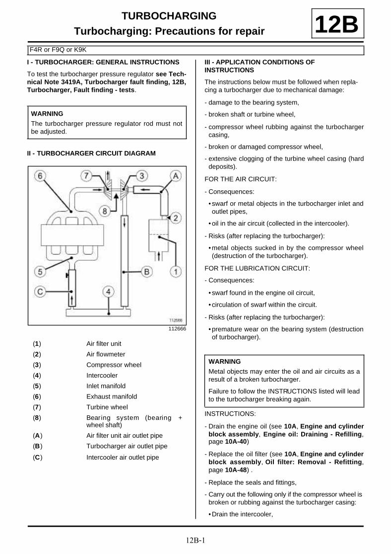
12B-1
TURBOCHARGINGTurbocharging: Precautions for repair
F4R or F9Q or K9K
12BI - TURBOCHARGER: GENERAL INSTRUCTIONS
To test the turbocharger pressure regulator see Tech-nical Note 3419A, Turbocharger fault finding, 12B,Turbocharger, Fault finding - tests.
II - TURBOCHARGER CIRCUIT DIAGRAM
III - APPLICATION CONDITIONS OF INSTRUCTIONS
The instructions below must be followed when repla-cing a turbocharger due to mechanical damage:
- damage to the bearing system,
- broken shaft or turbine wheel,
- compressor wheel rubbing against the turbochargercasing,
- broken or damaged compressor wheel,
- extensive clogging of the turbine wheel casing (harddeposits).
FOR THE AIR CIRCUIT:
- Consequences:
• swarf or metal objects in the turbocharger inlet andoutlet pipes,
• oil in the air circuit (collected in the intercooler).
- Risks (after replacing the turbocharger):
• metal objects sucked in by the compressor wheel(destruction of the turbocharger).
FOR THE LUBRICATION CIRCUIT:
- Consequences:
• swarf found in the engine oil circuit,
• circulation of swarf within the circuit.
- Risks (after replacing the turbocharger):
• premature wear on the bearing system (destructionof turbocharger).
INSTRUCTIONS:
- Drain the engine oil (see 10A, Engine and cylinderblock assembly, Engine oil: Draining - Refilling,page 10A-40)
- Replace the oil filter (see 10A, Engine and cylinderblock assembly, Oil filter: Removal - Refitting,page 10A-48) .
- Replace the seals and fittings,
- Carry out the following only if the compressor wheel is broken or rubbing against the turbocharger casing:
• Drain the intercooler,
WARNING
The turbocharger pressure regulator rod must notbe adjusted.
112666
(1) Air filter unit
(2) Air flowmeter
(3) Compressor wheel
(4) Intercooler
(5) Inlet manifold
(6) Exhaust manifold
(7) Turbine wheel
(8) Bearing system (bearing +wheel shaft)
(A) Air filter unit air outlet pipe
(B) Turbocharger air outlet pipe
(C) Intercooler air outlet pipe
WARNING
Metal objects may enter the oil and air circuits as aresult of a broken turbocharger.
Failure to follow the INSTRUCTIONS listed will leadto the turbocharger breaking again.

12B-2
TURBOCHARGINGTurbocharging: Precautions for repair
F4R or F9Q or K9K
12B• Clean the turbocharger air pipes.
IV - AIR CIRCUIT*: INSTRUCTIONS FOLLOWING MECHANICAL DAMAGE TO THE TURBOCHARGER
Remove the intercooler if fitted to the vehicle (see 12B,Turbocharging, Intercooler: Removal - Refitting,page 12B-37) .
Turn the intercooler over and allow the oil inside todrain out.
Check that there are no metal objects inside the flow-meter (2) .
Remove:
- the air pipe (A) (between the air filter box and the tur-bocharger),
- the air pipe (B) (between the turbocharger and the in-tercooler).
For air pipes comprising several components:
- mark (10) the fitting position of each component,
- separate all the components.
Note:
When carrying out an operation on the air or lubri-cation circuit, it is necessary to plug the open holesto prevent any risk of foreign bodies entering thesystem.
Note:
(*) These instructions for the air circuit are only to be followed in the case of:
- broken compressor wheel,
- compressor wheel rubbing against the turbochar-ger casing.
110738
Note:
If the compressor wheel (9) is damaged, metalobjects are ejected inside the air pipes.
112772
112770

12B-3
TURBOCHARGINGTurbocharging: Precautions for repair
F4R or F9Q or K9K
12BClean the removed pipes one by one using the clea-ning station:
- brush as much of the inside of the pipe as possible(only use brushes with plastic bristles),
- wash plenty of cleaning product from the cleaning sta-tion through the pipe,
- allow the cleaned pipe to drain by standing it upright,
- ensure the cleaning product has drained out comple-tely (check areas where liquid may be retained, e.g.gaiters, resonators etc.).
Dry the pipes one by one using a compressed air spraygun.
For pipes comprising several components:
- assemble the components, taking note of their correctfitting position (10) .
Refit:
- the air pipe (A) (between the air filter box and the tur-bocharger),
- the air pipe (B) (between the turbocharger and the in-tercooler).
Refit the intercooler, if fitted to the vehicle (see 12B,Turbocharging, Intercooler: Removal - Refitting,page 12B-37) .
V - LUBRICATION CIRCUIT**: INSTRUCTIONS FOLLOWING MECHANICAL DAMAGE TO THE TURBOCHARGER
Drain the engine oil (see 10A, Engine and cylinderblock assembly, Engine oil: Draining - Refilling,page 10A-40) .
Replace the oil filter (see 10A, Engine and cylinderblock assembly, Oil filter: Removal - Refitting, page10A-48) .
Fill the engine with a suitable oil type only (see Engineoil: Specifications) (Technical Note 6013A, 04A, Lu-bricants).
VI - GENERAL INSTRUCTIONS TO BE FOLLOWED WHEN REMOVING A TURBOCHARGER
Replace:
- the oil supply pipe:
• if the pipe is blocked, even partially (due to scale,carbonised oil etc.),
• if the pipe is fitted with self-retaining seals.
- the oil return pipe:
• if the pipe is blocked, even partially (due to scale,carbonised oil etc.),
• if the pipe is fitted with self-retaining seals.
- all seals that have been removed,
- all fittings that have been removed.
When starting the engine:
- do not accelerate,
- allow the engine to run for 1 minute,the time taken forthe oil circuit pressure to increase (until the oil pressu-re warning light on the instrument panel goes out),
- accelerate several times at no load,
- check the air circuit and the oil circuit for leaks.
112771
Note:
(**) These instructions relating to the lubrication cir-cuit must always be followed in all cases of mecha-nical damage as listed above.
WARNINGFailure to observe the following procedure may leadto destruction of the turbocharger.
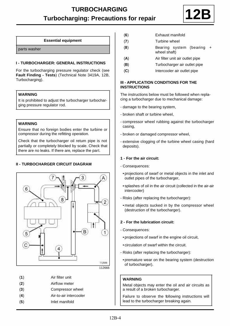
12B-4
TURBOCHARGINGTurbocharging: Precautions for repair 12B
I - TURBOCHARGER: GENERAL INSTRUCTIONS
For the turbocharging pressure regulator check (seeFault Finding - Tests) (Technical Note 3419A, 12B,Turbocharging).
II - TURBOCHARGER CIRCUIT DIAGRAM
III - APPLICATION CONDITIONS FOR THE INSTRUCTIONS
The instructions below must be followed when repla-cing a turbocharger due to mechanical damage:
- damage to the bearing system,
- broken shaft or turbine wheel,
- compressor wheel rubbing against the turbochargercasing,
- broken or damaged compressor wheel,
- extensive clogging of the turbine wheel casing (harddeposits).
1 - For the air circuit:
- Consequences:
• projections of swarf or metal objects in the inlet andoutlet pipes of the turbocharger,
• splashes of oil in the air circuit (collected in the air-airintercooler)
- Risks (after replacing the turbocharger):
• metal objects sucked in by the compressor wheel(destruction of the turbocharger).
2 - For the lubrication circuit:
- Consequences:
• projections of swarf in the engine oil circuit,
• circulation of swarf within the circuit.
- Risks (after replacing the turbocharger):
• premature wear on the bearing system (destructionof turbocharger).
Essential equipment
parts washer
WARNING
It is prohibited to adjust the turbocharger turbochar-ging pressure regulator rod.
WARNING
Ensure that no foreign bodies enter the turbine orcompressor during the refitting operation.
Check that the turbocharger oil return pipe is notpartially or completely blocked by scale. Check thatthere are no leaks. If there are, replace the part.
112666
(1) Air filter unit
(2) Airflow meter
(3) Compressor wheel
(4) Air-to-air intercooler
(5) Inlet manifold
(6) Exhaust manifold
(7) Turbine wheel
(8) Bearing system (bearing +wheel shaft)
(A) Air filter unit air outlet pipe
(B) Turbocharger air outlet pipe
(C) Intercooler air outlet pipe
WARNING
Metal objects may enter the oil and air circuits asa result of a broken turbocharger.
Failure to observe the following instructions willlead to the turbocharger breaking again.
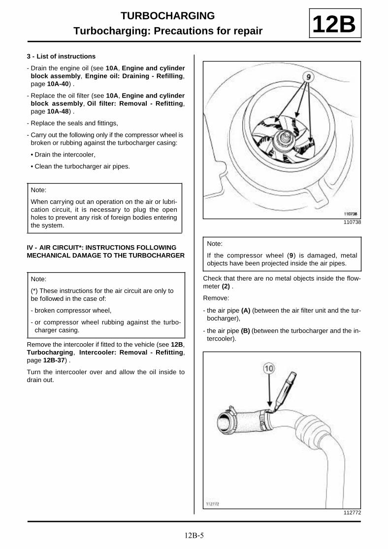
12B-5
TURBOCHARGINGTurbocharging: Precautions for repair 12B
3 - List of instructions
- Drain the engine oil (see 10A, Engine and cylinderblock assembly, Engine oil: Draining - Refilling,page 10A-40) .
- Replace the oil filter (see 10A, Engine and cylinderblock assembly, Oil filter: Removal - Refitting,page 10A-48) .
- Replace the seals and fittings,
- Carry out the following only if the compressor wheel is broken or rubbing against the turbocharger casing:
• Drain the intercooler,
• Clean the turbocharger air pipes.
IV - AIR CIRCUIT*: INSTRUCTIONS FOLLOWING MECHANICAL DAMAGE TO THE TURBOCHARGER
Remove the intercooler if fitted to the vehicle (see 12B,Turbocharging, Intercooler: Removal - Refitting,page 12B-37) .
Turn the intercooler over and allow the oil inside todrain out.
Check that there are no metal objects inside the flow-meter (2) .
Remove:
- the air pipe (A) (between the air filter unit and the tur-bocharger),
- the air pipe (B) (between the turbocharger and the in-tercooler).
Note:
When carrying out an operation on the air or lubri-cation circuit, it is necessary to plug the openholes to prevent any risk of foreign bodies enteringthe system.
Note:
(*) These instructions for the air circuit are only to be followed in the case of:
- broken compressor wheel,
- or compressor wheel rubbing against the turbo-charger casing.
110738
Note:
If the compressor wheel (9) is damaged, metalobjects have been projected inside the air pipes.
112772

12B-6
TURBOCHARGINGTurbocharging: Precautions for repair 12B
For air pipes made up of several components:
- mark (10) the fitting position of each component,
- separate all the components.
One by one, clean the pipes removed with the parts washer :
- brush as much of the inside of the pipe as possible(only use brushes with plastic bristles),
- wash plenty of cleaning product from the cleaning sta-tion through the pipe,
- allow the cleaned pipe to drain by standing it upright,
- ensure that the cleaning product has drained outcompletely (check areas where liquid may be retai-ned: gaiters, resonator, etc.).
Dry the pipes one by one using a compressed air gun.
For pipes comprising several components:
- assemble the components, taking note of their correctfitting position (10) .
Refit:
- the air pipe(between the air filter unit and the turbo-charger) (A) ,
- the air pipe (B) (between the turbocharger and the in-tercooler).
Refit the intercooler, if fitted to the vehicle (see 12B,Turbocharging, Intercooler: Removal - Refitting,page 12B-37) .
V - LUBRICATION CIRCUIT**: INSTRUCTIONS FOLLOWING MECHANICAL DAMAGE TO THE TURBOCHARGER
Drain the engine oil (see 10A, Engine and cylinderblock assembly, Engine oil: Draining - Refilling,page 10A-40) .
Replace the oil filter (see 10A, Engine and cylinderblock assembly, Oil filter: Removal - Refitting, page10A-48) .
Fill the engine with the correct type of oil only (see En-gine oil: Specifications) .
112770
112771
Note:
(**) These instructions relating to the lubrication cir-cuit must always be followed in all cases of mecha-nical damage as listed above.
12B-7
TURBOCHARGINGTurbocharging: Precautions for repair 12B
VI - GENERAL INSTRUCTIONS TO BE FOLLOWED WHEN REMOVING A TURBOCHARGER
Always replace:
- the oil supply pipe:
• if the pipe is blocked, even partially (due to scale,carbonised oil etc.),
• if the pipe is fitted with self-retaining seals.
- the oil return pipe:
• if the pipe is blocked, even partially (due to scale,carbonised oil etc.),
• if the pipe is fitted with self-retaining seals.
- all seals that have been removed,
- all fittings that have been removed.
When starting the engine:
- do not accelerate,
- allow the engine to run for 1 minute,the time taken forthe oil circuit pressure to increase (until the oil pressu-re warning light on the instrument panel goes out),
- accelerate several times at no load,
- check the air circuit and the oil circuit for leaks.
WARNING
Failure to observe the following procedure may leadto destruction of the turbocharger.

12B-8
TURBOCHARGINGTurbocharger: Removal - Refitting
F9Q
12B
REMOVAL
I - REMOVAL PREPARATION OPERATION
a Position the vehicle on a two-post lift (see Vehicle:Towing and lifting) (02A, Lifting equipment).
a Remove:
- the engine cover,
- the engine undertray bolts,
- the engine undertray,
- the windscreen wiper arms (see Windscreen wi-per arm: Removal - Refitting) (85A, Wiping -Washing),
- the scuttle panel grille (see Scuttle panel grille:Removal - Refitting) (56A, Exterior equipment),
- the scoop under the scuttle panel grille (see Scoopunder scuttle panel grille: Removal - Refitting)(56A, Exterior equipment),
- the battery (see Battery : Removal - Refitting)(80A, Battery),
- the battery tray (see Battery tray: Removal - Re-fitting) (80A, Battery),
- the intercooler air inlet pipe (see 12B, Turbochar-ging, Intercooler air inlet pipe: Removal - Refit-ting, page 12B-41) ,
- the exhaust gas recirculation rigid pipes (see 14A,Antipollution, Exhaust gas recirculation rigidpipe: Removal - Refitting, page 14A-30) ,
- the exhaust gas recirculation assembly (see 14A,Antipollution, Exhaust gas recirculation as-sembly: Removal - Refitting, page 14A-18) ,
- the exhaust gases duct at the turbocharger outlet(see 12B, Turbocharging, Turbocharger outletexhaust gas duct: Removal - Refitting, page12B-49) ,
- the turbocharger oil pipe (see 12B, Turbochar-ging, Turbocharger oil pipe: Removal - Refit-ting, page 12B-22) ,
- the lower engine tie-bar (see 19D, Engine moun-ting, Lower engine tie-bar: Removal - Refitting,page 19D-33) .
II - OPERATION FOR REMOVAL OF PART CONCERNED
a Remove:
- the bolts (1) from the turbocharger strut,
- the turbocharger strut.
Tightening torquesm
turbocharger nuts 25 Nm
turbocharger bracketbolts
25 N.m
137469
137470
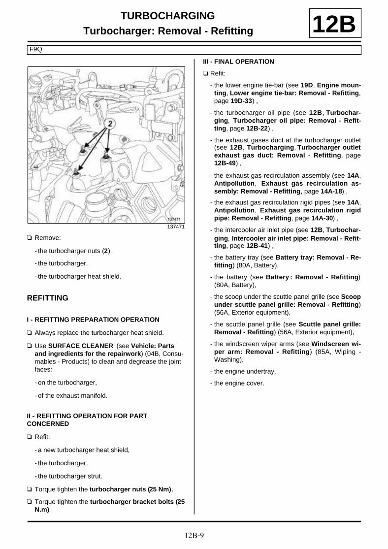
12B-9
TURBOCHARGINGTurbocharger: Removal - Refitting
F9Q
12B
a Remove:
- the turbocharger nuts (2) ,
- the turbocharger,
- the turbocharger heat shield.
REFITTING
I - REFITTING PREPARATION OPERATION
a Always replace the turbocharger heat shield.
a Use SURFACE CLEANER (see Vehicle: Parts and ingredients for the repairwork) (04B, Consu-mables - Products) to clean and degrease the joint faces:
- on the turbocharger,
- of the exhaust manifold.
II - REFITTING OPERATION FOR PART CONCERNED
a Refit:
- a new turbocharger heat shield,
- the turbocharger,
- the turbocharger strut.
a Torque tighten the turbocharger nuts (25 Nm).
a Torque tighten the turbocharger bracket bolts (25N.m).
III - FINAL OPERATION
a Refit:
- the lower engine tie-bar (see 19D, Engine moun-ting, Lower engine tie-bar: Removal - Refitting,page 19D-33) ,
- the turbocharger oil pipe (see 12B, Turbochar-ging, Turbocharger oil pipe: Removal - Refit-ting, page 12B-22) ,
- the exhaust gases duct at the turbocharger outlet(see 12B, Turbocharging, Turbocharger outletexhaust gas duct: Removal - Refitting, page12B-49) ,
- the exhaust gas recirculation assembly (see 14A,Antipollution, Exhaust gas recirculation as-sembly: Removal - Refitting, page 14A-18) ,
- the exhaust gas recirculation rigid pipes (see 14A,Antipollution, Exhaust gas recirculation rigidpipe: Removal - Refitting, page 14A-30) ,
- the intercooler air inlet pipe (see 12B, Turbochar-ging, Intercooler air inlet pipe: Removal - Refit-ting, page 12B-41) ,
- the battery tray (see Battery tray: Removal - Re-fitting) (80A, Battery),
- the battery (see Battery : Removal - Refitting)(80A, Battery),
- the scoop under the scuttle panel grille (see Scoopunder scuttle panel grille: Removal - Refitting)(56A, Exterior equipment),
- the scuttle panel grille (see Scuttle panel grille:Removal - Refitting) (56A, Exterior equipment),
- the windscreen wiper arms (see Windscreen wi-per arm: Removal - Refitting) (85A, Wiping -Washing),
- the engine undertray,
- the engine cover.
137471

12B-10
TURBOCHARGINGTurbocharger: Removal - Refitting
K9K, and 830 or 832
12B
REMOVAL
I - REMOVAL PREPARATION OPERATION
a Position the vehicle on a two-post lift (see Vehicle:Towing and lifting) (02A, Lifting equipment).
a Disconnect the battery (see Battery : Removal -Refitting) (80A, Battery).
a Remove:
- the engine cover,
- the engine undertray bolts,
- the engine undertray.
a Remove the lower engine tie-bar (see 19D, Enginemounting, Lower engine tie-bar: Removal - Refit-ting, page 19D-33) .
a Remove:
- the catalytic converter (see 19B, Exhaust, Cataly-tic converter: Removal - Refitting, page 19B-17),
- the turbocharger oil return pipe (see 12B, Turbo-charging, Turbocharger oil pipe: Removal - Re-fitting, page 12B-22) ,
- the turbocharger air outlet pipe (see 12B, Turbo-charging, Intercooler air inlet pipe: Removal -Refitting, page 12B-41) ,
- the turbocharger oil supply pipe (see 12B, Turbo-charging, Turbocharger oil pipe: Removal - Re-fitting, page 12B-22) .
II - OPERATION FOR REMOVAL OF PART CONCERNED
a Disconnect the turbocharging pressure regulationvalve control hose from the turbocharger.
a Remove:
- the turbocharger nuts (1) ,
- the turbocharger,
- the turbocharger seal.
Tightening torquesm
turbocharger studs onthe exhaust manifold
9 Nm
turbocharger stud onthe turbocharger
9 Nm
turbocharger nuts 28 Nm
IMPORTANT
Wear protective gloves during the operation.
K9K, and 830
K9K, and 832
113560

12B-11
TURBOCHARGINGTurbocharger: Removal - Refitting
K9K, and 830 or 832
12B
a Remove:
- the turbocharger nuts (1) ,
- the turbocharger,
- the turbocharger seal.
REFITTING
I - REFITTING PREPARATION OPERATION
a
a parts always to be replaced: seal between ex-haust manifold and turbocharger (10,09,01,07).
a Use ABRASIVE PADS to clean the joint faces:
- the exhaust manifold,
- of the turbocharger if reused.
a Use SURFACE CLEANER (see Vehicle: Parts and ingredients for the repairwork) (04B, Consu-mables - Products) and CLEAN CLOTHS to clean and degrease the joint faces:
- the exhaust manifold,
- of the turbocharger if reused.
a When replacing the turbocharger studs, torque tigh-ten:
- the turbocharger studs on the exhaust manifold(9 Nm),
- the turbocharger stud on the turbocharger (9Nm).
II - REFITTING OPERATION FOR PART CONCERNED
a Refit:
- a new seal between the exhaust manifold and theturbocharger on the exhaust manifold,
- the turbocharger.
a Torque tighten the turbocharger nuts (28 Nm).
a Connect the turbocharger pressure regulating valvecontrol hose.
III - FINAL OPERATION
a Refit:
- the turbocharger oil supply pipe (see 12B, Turbo-charging, Turbocharger oil pipe: Removal - Re-fitting, page 12B-22) ,
- the turbocharger air outlet pipe (see 12B, Turbo-charging, Intercooler air inlet pipe: Removal -Refitting, page 12B-41) ,
- the turbocharger oil return pipe (see 12B, Turbo-charging, Turbocharger oil pipe: Removal - Re-fitting, page 12B-22) ,
- the catalytic converter (see 19B, Exhaust, Cataly-tic converter: Removal - Refitting, page 19B-17).
K9K, and 830
136391
WARNING
Ensure that no foreign bodies enter the turbine orcompressor during the refitting operation.
Check that the turbocharger oil return pipe is notpartially or completely blocked by scale. Checkthat there are no leaks. If there are, replace thepart.
WARNING
Following a turbocharger fault, check that theintercooler and air circuit assembly are not full ofoil. If they are, remove them and clean them witha cleaning tray or station and dry them with acompressed air gun.

12B-12
TURBOCHARGINGTurbocharger: Removal - Refitting
K9K, and 830 or 832
12B
a Refit the lower engine tie-bar (see 19D, Enginemounting, Lower engine tie-bar: Removal - Refit-ting, page 19D-33) .
a Refit:
- the engine undertray,
- the engine cover.
a Connect the battery (see Battery : Removal - Refit-ting) (80A, Battery).
K9K, and 830

12B-13
TURBOCHARGINGTurbocharger: Removal - Refitting
F4R
12B
REMOVAL
I - REMOVAL PREPARATION OPERATION
a Position the vehicle on a two-post lift (see Vehicle:Towing and lifting) (02A, Lifting equipment).
a Remove:
- the engine undertray bolts,
- the engine undertray,
- the engine cover.
a Disconnect the battery (see Battery : Removal -Refitting) (80A, Battery).
a Remove:
- the windscreen wiper arms (see Windscreen wi-per arm: Removal - Refitting) (85A, Wiping -Washing),
- the scuttle panel grille (see Scuttle panel grille:Removal - Refitting) (56A, Exterior equipment),
- the scoop under the scuttle panel grille (see Scoopunder scuttle panel grille: Removal - Refitting)(56A, Exterior equipment),
Essential special tooling
Ms. 583 Hose clamp pliers.
Tightening torquesm
turbocharger studs 8.5 N.m
turbocharger oil returnpipe bolts
12 Nm
turbocharger coolingduct bolts
12 N.m
turbocharger upper nut 15 N.m + 75˚ ±±±±6
turbocharger lower nuts 15 N.m + 75˚ ±±±±6
clip for the air filter unitair outlet pipe at the airfilter unit end
6 N.m
clip for the air filter unitair outlet pipe at thethrottle unit end
6 N.m
clip for the intercoolerair inlet pipe
6 N.m
catalytic converter strutbolt
8 N.m
catalytic converter strutnut
44 N.m
relay bearing bolts 44 N.m
lower engine tie-barsupport bolts
62 N.m
IMPORTANT
Wear heat protective gloves during the operation.
WARNING
The turbocharger pressure regulator rod must notbe adjusted.
WARNING
Metal objects may enter the oil and air circuits as aresult of a broken turbocharger.
Failure to observe the following instructions will leadto the turbocharger breaking again.
WARNINGFollowing a turbocharger fault, check that the inter-cooler and air circuit assembly are not full of oil. Ifthey are, remove them and clean them with a clea-ning tray or station and dry them with a compressedair gun.

12B-14
TURBOCHARGINGTurbocharger: Removal - Refitting
F4R
12B
a
Remove:
- the bolts (1) from the turbocharger heat shield,
- the turbocharger heat shield.
a Remove:
- the bolt (2) from the lifting eye,
- the lifting eye,
- the front right-hand wheel (see Wheel: Removal -Refitting) (35A, Wheels and tyres),
- the front section of the front right-hand wheel archliner (see Front wheel arch liner: Removal - Re-fitting) (55A, Exterior protection).
a Drain the manual gearbox (see Manual gearboxoil: Draining - Refilling) (21A, Manual gearbox).
a Remove:
- the front right-hand wheel driveshaft (see Front ri-ght-hand wheel driveshaft: Removal - Refitting)(29A, Driveshafts),
- the right-hand differential output seal (see Diffe-rential output seal: Removal - Refitting) (21A,Manual gearbox),
- the lower engine tie-bar (see 19D, Engine moun-ting, Lower engine tie-bar: Removal - Refitting,page 19D-33) .
a Remove:
- the lower engine tie-bar mounting bolts (3) ,
- the lower engine tie-bar support.
134649
WARNING
To prevent the surrounding components fromoverheating, do not damage (tear, pierce, bend,etc.) a heat shield.
Any damaged heat shields must be replaced.
137955
136504

12B-15
TURBOCHARGINGTurbocharger: Removal - Refitting
F4R
12B
a Remove:
- the bolts (4) from the relay bearing support,
- the relay bearing support.
a Remove:
- the catalytic converter side stay nuts (5) ,
- the catalytic converter strut.
a Remove:
- the bolts (6) from the bulkhead upper heat shield,
- the bulkhead upper heat shield,
- the connecting hose (see 19B, Exhaust, Connec-ting hose: Removal - Refitting, page 19B-60) ,
- the catalytic converter (see 19B, Exhaust, Cataly-tic converter: Removal - Refitting, page 19B-17),
- the turbocharger oil pipes (see 12B, Turbochar-ging, Turbocharger oil pipe: Removal - Refit-ting, page 12B-22) .
a Fit the tools (Ms. 583) onto the turbocharger coolinghoses.
a Disconnect the turbocharger cooling hoses.
135708
111627
136467
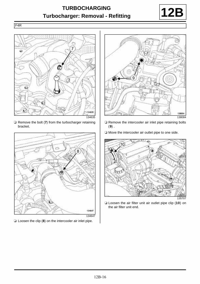
12B-16
TURBOCHARGINGTurbocharger: Removal - Refitting
F4R
12B
a Remove the bolt (7) from the turbocharger retainingbracket.
a Loosen the clip (8) on the intercooler air inlet pipe.
a Remove the intercooler air inlet pipe retaining bolts(9) .
a Move the intercooler air outlet pipe to one side.
a Loosen the air filter unit air outlet pipe clip (10) onthe air filter unit end.
134635
134647
138084
135707
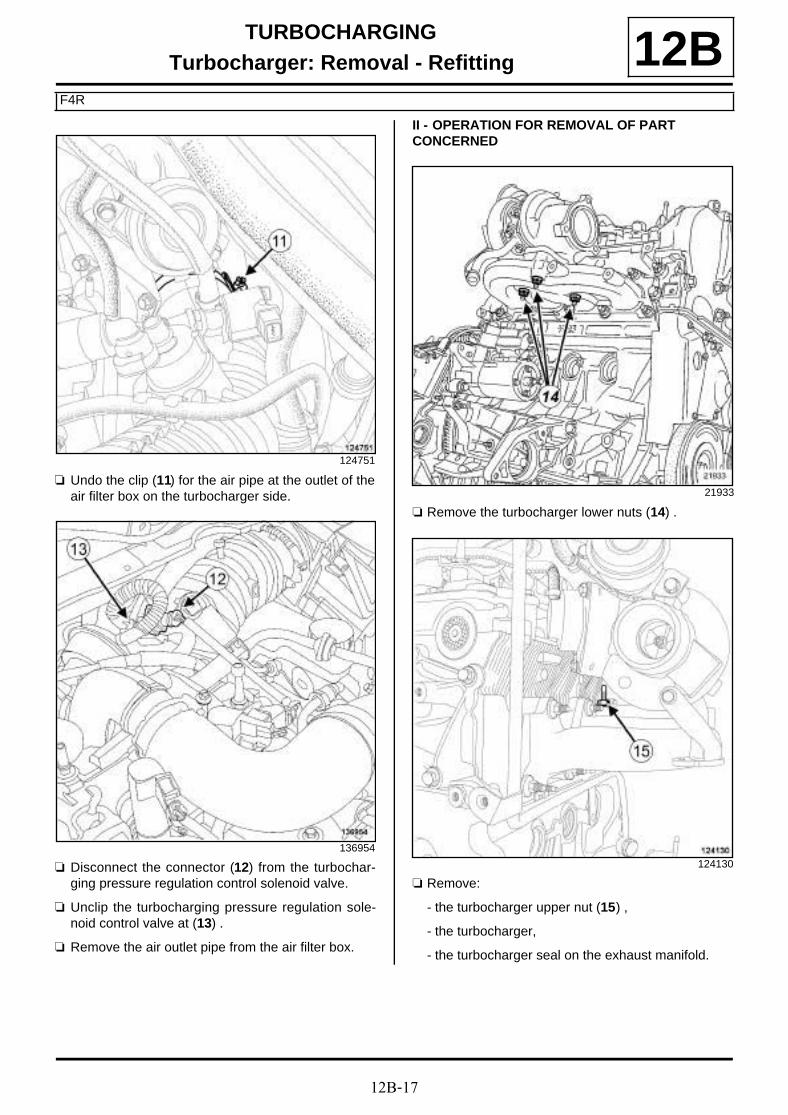
12B-17
TURBOCHARGINGTurbocharger: Removal - Refitting
F4R
12B
a Undo the clip (11) for the air pipe at the outlet of theair filter box on the turbocharger side.
a Disconnect the connector (12) from the turbochar-ging pressure regulation control solenoid valve.
a Unclip the turbocharging pressure regulation sole-noid control valve at (13) .
a Remove the air outlet pipe from the air filter box.
II - OPERATION FOR REMOVAL OF PART CONCERNED
a Remove the turbocharger lower nuts (14) .
a Remove:
- the turbocharger upper nut (15) ,
- the turbocharger,
- the turbocharger seal on the exhaust manifold.
124751
136954
21933
124130

12B-18
TURBOCHARGINGTurbocharger: Removal - Refitting
F4R
12BREFITTING
I - REFITTING PREPARATION OPERATION
a parts always to be replaced: seal between ex-haust manifold and turbocharger (10,09,01,07).
a parts always to be replaced: turbocharger oilpipe seal (10,09,03,05).
a parts always to be replaced: Turbocharger nut(10,09,01,03).
a Use SURFACE CLEANER (see Vehicle: Parts and ingredients for the repairwork) (04B, Consu-mables - Products) to clean and degrease:
- the exhaust manifold joint face,
- the turbocharger gasket face if reused.
If replacing the turbocharger
a Remove:
- the turbocharger oil return pipe bolts
- the bolts from the turbocharger cooling duct,
- the oil return pipe,
- the turbocharger cooling duct,
- the oil return pipe seals.
a Use SURFACE CLEANER (see Vehicle: Partsand ingredients for the repairwork) (04B, Consu-mables - Products) to clean and degrease the jointface of the turbocharger oil return pipe.
a Refit:
- a new turbocharger oil return pipe seal to the turbo-charger oil return pipe,
- a new turbocharger oil return pipe to the turbochar-ger,
- the oil return pipe retaining bolts to the turbochar-ger,
- the turbocharger cooling duct,
- the turbocharger cooling duct retaining bolts.
a Tighten to torque:
- the turbocharger oil return pipe bolts (12 Nm),
- the turbocharger cooling duct bolts (12 N.m).
II - REFITTING OPERATION FOR PART CONCERNED
a Refit:
- a new seal between the turbocharger and the ex-haust manifold,
- the turbocharger,
- a new upper nut to the turbocharger,
- new lower nuts to the turbocharger.
a Tighten to torque:
- the turbocharger upper nut (15 N.m + 75˚ ±±±± 6),
- the turbocharger lower nuts (15 N.m + 75˚ ±±±± 6).
III - FINAL OPERATION
a Refit the air outlet pipe onto the air filter unit.
a Tighten to torque:
- the clip for the air filter unit air outlet pipe at theair filter unit end (6 N.m),
- the clip for the air filter unit air outlet pipe at thethrottle unit end (6 N.m).
a Clip:
- the turbocharging pressure regulation valve controlsolenoid valve,
- the vacuum pipe from the brake servo.
a Connect the connector for the turbocharging pressu-re regulation control solenoid valve.
a Fit:
- the air pipe at the intercooler inlet,
- the retaining bracket bolts for the intercooler air in-let pipe.
a Torque tighten the clip for the intercooler air inletpipe (6 N.m).
a Refit the bolt for the turbocharger retaining bracket.
a Connect the turbocharger cooling hoses.
Note:
If a stud comes loose during removal, coat it withHIGH RESISTANCE THREADLOCK (see Vehi-cle: Parts and consumables for repair) (04B,Consumables - Products).
Torque tighten the turbocharger studs (8.5N.m).
WARNING
Ensure that no foreign bodies enter the turbine orcompressor during the refitting operation.
Check that the turbocharger oil return pipe is notpartially or completely blocked due to scale.Check that there are no leaks. If there are,replace the part.

12B-19
TURBOCHARGINGTurbocharger: Removal - Refitting
F4R
12Ba Remove the tools (Ms. 583) from the turbocharger
cooling hoses.
a Refit:
- the turbocharger oil pipes (see 12B, Turbochar-ging, Turbocharger oil pipe: Removal - Refit-ting, page 12B-22) ,
- the catalytic converter (see 19B, Exhaust, Cataly-tic converter: Removal - Refitting, page 19B-17),
- the bulkhead upper heat shield,
- Refit the catalytic converter strut.
a Tighten to torque:
- the catalytic converter strut bolt (8 N.m),
- the catalytic converter strut nut (44 N.m).
a Refit the relay bearing.
a Torque tighten the relay bearing bolts (44 N.m).
a Refit the lower engine tie-bar support.
a Torque tighten the lower engine tie-bar supportbolts (62 N.m).
a Refit:
- the lower engine tie-bar (see 19D, Engine moun-ting, Lower engine tie-bar: Removal - Refitting,page 19D-33) ,
- a new right-hand differential output seal (see Diffe-rential output seal: Removal - Refitting) (21A,Manual gearbox),
- the front right-hand wheel driveshaft (see Front ri-ght-hand wheel driveshaft: Removal - Refitting)(29A, Driveshafts).
a Fill the manual gearbox (see Manual gearbox oil:Draining - Refilling) (21A, Manual gearbox).
a Refit:
- the connecting hose (see 19B, Exhaust, Connec-ting hose: Removal - Refitting, page 19B-60) ,
- the engine undertray,
- the front section of the front right-hand wheel archliner (see Front wheel arch liner: Removal - Re-fitting) (55A, Exterior protection),
- the front right-hand wheel (see Wheel: Removal -Refitting) (35A, Wheels and tyres),
- the lifting eye,
- the turbocharger heat shield.
a Refit:
- the scoop under the scuttle panel grille (see Scoopunder scuttle panel grille: Removal - Refitting)(56A, Exterior equipment),
- the scuttle panel grille (see Scuttle panel grille:Removal - Refitting) (56A, Exterior equipment),
- the windscreen wiper arms (see Rear screen wi-per arm: Removal - Refitting) (85A, Wiping -Washing).
a Connect the battery (see Battery : Removal - Refit-ting) (80A, Battery).
a Refit the engine cover.

12B-20
TURBOCHARGINGTurbocharger: Removal - Refitting
K9K, and 836
12B
REMOVAL
I - REMOVAL PREPARATION OPERATION
a Position the vehicle on a two-post lift (see Vehicle:Towing and lifting) (02A, Lifting equipment).
a Remove:
- the engine cover,
- the engine undertray bolts,
- the engine undertray,
- the exhaust gases duct at the turbocharger outlet(see 12B, Turbocharging, Turbocharger outletexhaust gas duct: Removal - Refitting, page12B-49) ,
- the turbocharger oil supply pipe (see 12B, Turbo-charging, Turbocharger oil pipe: Removal - Re-fitting, page 12B-22) ,
- the turbocharger oil return pipe (see 12B, Turbo-charging, Turbocharger oil pipe: Removal - Re-fitting, page 12B-22) ,
- the exhaust gas recirculation rigid pipe (see 14A,Antipollution, Exhaust gas recirculation rigidpipe: Removal - Refitting, page 14A-30) ,
- the exhaust gas recirculation assembly (see 14A,Antipollution, Exhaust gas recirculation as-sembly: Removal - Refitting, page 14A-18) .
II - OPERATION FOR REMOVAL OF PART CONCERNED
a Remove:
- the turbocharger nuts (1) ,
- the turbocharger,
- the turbocharger seal.
REFITTING
I - REFITTING PREPARATION OPERATION
a
a parts always to be replaced: seal between ex-haust manifold and turbocharger (10,09,01,07).
Tightening torquesm
turbocharger studs onthe exhaust manifold
9 N.m
turbocharger stud onthe turbocharger
9 N.m
turbocharger nuts 28 N.m
100000-1
WARNING
Ensure that no foreign bodies enter the turbine orcompressor during the refitting operation.
Check that the turbocharger oil return pipe is notpartially or completely blocked by scale. Checkthat there are no leaks. If there are, replace thepart.
WARNING
Following a turbocharger fault, check that theintercooler and air circuit assembly are not full ofoil. If they are, remove them and clean them witha cleaning tray or station and dry them with acompressed air gun.

12B-21
TURBOCHARGINGTurbocharger: Removal - Refitting
K9K, and 836
12Ba Use ABRASIVE PADS to clean the joint faces:
- the exhaust manifold,
- of the turbocharger if reused.
a Use SURFACE CLEANER (see Vehicle: Parts and ingredients for the repairwork) (04B, Consu-mables - Products) and CLEAN CLOTHS to clean and degrease the joint faces:
- the exhaust manifold,
- of the turbocharger if reused.
a When replacing the turbocharger studs, torque tigh-ten:
- the turbocharger studs on the exhaust manifold(9 N.m),
- the turbocharger stud on the turbocharger (9N.m).
II - REFITTING OPERATION FOR PART CONCERNED
a Refit the turbocharger fitted with a new seal.
a Torque tighten the turbocharger nuts (28 N.m).
III - FINAL OPERATION
a Refit:
- the exhaust gas recirculation assembly (see 14A,Antipollution, Exhaust gas recirculation as-sembly: Removal - Refitting, page 14A-18) ,
- the exhaust gas recirculation rigid pipe (see 14A,Antipollution, Exhaust gas recirculation rigidpipe: Removal - Refitting, page 14A-30) ,
- the turbocharger oil return pipe (see 12B, Turbo-charging, Turbocharger oil pipe: Removal - Re-fitting, page 12B-22) ,
- the turbocharger oil supply pipe (see 12B, Turbo-charging, Turbocharger oil pipe: Removal - Re-fitting, page 12B-22) ,
- the exhaust gases duct at the turbocharger outlet(see 12B, Turbocharging, Turbocharger outletexhaust gas duct: Removal - Refitting, page12B-49) ,
- the engine undertray,
- the engine cover.

12B-22
TURBOCHARGINGTurbocharger oil pipe: Removal - Refitting
K9K, and 830 or 832
12B
REMOVING THE TURBOCHARGER OIL SUPPLY PIPE
I - REMOVAL PREPARATION OPERATION
a Disconnect the battery (see Battery : Removal -Refitting) (80A, Battery).
a Remove the front engine cover.
a Disconnect:
- the oil vapour rebreathing pipe union from the airfilter unit air outlet pipe,
- the oil vapour rebreathing pipe from the rocker co-ver.
a Remove the oil vapour rebreathing pipe.
Essential special tooling
Mot. 1566 Spanner for removing highpressure pipes.
Mot. 1746 Offset spanner for tighteninghigh pressure pump pipes.
Essential equipment
self-contained starter
diagnostic tool
Tightening torquesm
turbocharger oil supplypipe nut on the cylinderhead
35 N.m
turbocharger oil supplypipe hollow bolt
14 N.m
clip for the air filter unitair outlet pipe clip on theturbocharger
5.5 N.m
clip for the air filter unitair outlet pipe on the airfilter unit
5.5 N.m
turbocharger oil returnpipe bolts
12 N.m
Note:
This procedure deals with removing and refitting theturbocharger oil return pipe and the turbocharger oilsupply pipe.
IMPORTANT
Wear leaktight gloves (Nitrile type) for this opera-tion.
IMPORTANT
Wear protective gloves during the operation.
WARNING
Ensure that no foreign bodies enter the turbine orcompressor during the refitting operation.
Check that the turbocharger oil return pipe is notpartially or completely blocked by scale. Check thatthere are no leaks. If there are, replace the part.
WARNING
Metal objects may enter the oil and air circuits as aresult of a broken turbocharger.
Failure to observe the following instructions will leadto the turbocharger breaking again.
K9K, and 832

12B-23
TURBOCHARGINGTurbocharger oil pipe: Removal - Refitting
K9K, and 830 or 832
12B
a Disconnect the oil vapour rebreathing pipe from theair filter unit air outlet pipe (1) .
a Unclip the air flowmeter wiring from the air filter unitair outlet pipe at (2) .
a Loosen the clip (3) of the air filter unit air outlet pipefrom the air filter unit.
a Disconnect the air filter unit air outlet pipe from theair filter unit.
a Undo the air filter unit air outlet pipe clip (4) from theturbocharger.
a Disconnect the air filter unit air outlet pipe from theturbocharger.
a Remove the air outlet pipe from the air filter box.
K9K, and 830
135880
134038
136639

12B-24
TURBOCHARGINGTurbocharger oil pipe: Removal - Refitting
K9K, and 830 or 832
12BII - OPERATION FOR REMOVAL OF PART CONCERNED
a Remove the turbocharger oil supply pipe hollow bolt(5) .
a Loosen the nut (6) for the turbocharger oil supplypipe on the cylinder head, using the tool (Mot. 1566)or the tool (Mot. 1746).
a Remove the nut (6) for the turbocharger oil supplypipe from the cylinder head.
a Remove the turbocharger oil supply pipe hollow bolt(5) .
a Loosen the nut (6) for the turbocharger oil supplypipe on the cylinder head, using the tool (Mot. 1566)or the tool (Mot. 1746).
a Remove the nut (6) for the turbocharger oil supplypipe from the cylinder head.
a Remove the turbocharger oil supply pipe.
a Wipe away any oil run-off.
REFITTING THE TURBOCHARGER OIL SUPPLY PIPE
I - REFITTING PREPARATION OPERATION
a parts always to be replaced: turbocharger oilsupply pipe (10,09,03,01).
a parts always to be replaced: Turbocharger oilsupply pipe bolt (10,09,03,04).
II - REFITTING OPERATION FOR PART CONCERNED
a Fit a new turbocharger oil supply pipe.
a Fit the nut for the new turbocharger oil supply pipe tothe cylinder head, without tightening it.
K9K, and 832
135487
K9K, and 830
136643

12B-25
TURBOCHARGINGTurbocharger oil pipe: Removal - Refitting
K9K, and 830 or 832
12Ba Refit a new hollow bolt for the turbocharger oil sup-
ply pipe bolt on the turbocharger.
a Tighten to torque:
- the turbocharger oil supply pipe nut on the cy-linder head (35 N.m) using the tool (Mot. 1566) orthe tool (Mot. 1746),
- the turbocharger oil supply pipe hollow bolt (14N.m),
III - FINAL OPERATION
a Fit the air filter unit air outlet pipe.
a Connect the air filter unit air outlet pipe to the turbo-charger.
a Torque tighten the clip for the air filter unit air out-let pipe clip on the turbocharger (5.5 N.m).
a Connect the air filter unit air outlet pipe to the air filterunit.
a Torque tighten the clip for the air filter unit air out-let pipe on the air filter unit (5.5 N.m).
a Clip the air flowmeter wiring onto the air filter unit airoutlet pipe.
a Fit the oil vapour rebreathing pipe.
a Connect the oil vapour rebreathing pipe onto therocker cover.
a Connect the oil vapour rebreathing union to the airfilter unit air outlet pipe.
a Refit the engine cover.
a Connect the battery (see Battery : Removal - Refit-ting) (80A, Battery).
a Disconnect the high pressure pump flow actuatorconnector and the connector for each diesel fuel in-jector in order to prevent the engine from starting.
a Connect a self-contained starter.
a Run the starter until the oil pressure warning lightgoes out on the instrument panel (wait for a few se-conds).
a Switch off the ignition.
a Disconnect the self-contained starter.
a Connect the high pressure pump flow actuator con-nector and the connector for each diesel fuel injec-tor.
a Start the engine.
a Let the engine idle then depress the accelerator se-veral times with no load.
a Switch off the ignition.
a Check:
- that the turbocharger is operating correctly,
- that there are no oil leaks from the turbocharger.
a Use the diagnostic tool to check for an absence ofstored faults; deal with these and clear them as ne-cessary.
REMOVING THE TURBOCHARGER OIL RETURN PIPE
I - REMOVAL PREPARATION OPERATION
a Position the vehicle on a two-post lift (see Vehicle:Towing and lifting) (02A, Lifting equipment).
a Disconnect the battery (see Battery : Removal -Refitting) (80A, Battery).
a Remove:
- the engine undertray bolts,
- the engine undertray.
a Remove the lower engine tie-bar (see 19D, Enginemounting, Lower engine tie-bar: Removal - Refit-ting, page 19D-33) .
a Remove the catalytic converter (see 19B, Exhaust,Catalytic converter: Removal - Refitting, page19B-17) .
K9K, and 832
K9K, and 830

12B-26
TURBOCHARGINGTurbocharger oil pipe: Removal - Refitting
K9K, and 830 or 832
12BII - OPERATION FOR REMOVAL OF PART CONCERNED
a Remove the turbocharger oil return pipe bolts (1) .a Remove the turbocharger oil return pipe bolts (1) .
a Turn the turbocharger oil return pipe to facilitate itsremoval.
a Extract the turbocharger oil return pipe from the cy-linder block.
K9K, and 832
135843
135488
K9K, and 830
135844
136641

12B-27
TURBOCHARGINGTurbocharger oil pipe: Removal - Refitting
K9K, and 830 or 832
12BREFITTING THE TURBOCHARGER OIL RETURN PIPE
I - REFITTING PREPARATION OPERATION
a parts always to be replaced: turbocharger oilpipe seal (10,09,03,05).
a Lubricate the new turbocharger oil return pipe O-ringwith clean engine oil.
II - REFITTING OPERATION FOR PART CONCERNED
a Fit a new turbocharger oil return pipe equipped witha new seal.
a Refit the turbocharger oil return pipe bolts.
a Torque tighten the turbocharger oil return pipebolts (12 N.m).
III - FINAL OPERATION
a Refit the catalytic converter (see 19B, Exhaust, Ca-talytic converter: Removal - Refitting, page 19B-17) .
a Refit the lower engine tie-bar (see 19D, Enginemounting, Lower engine tie-bar: Removal - Refit-ting, page 19D-33) .
a Refit the engine undertray.
a Connect the battery (see Battery : Removal - Refit-ting) (80A, Battery).
K9K, and 830

12B-28
TURBOCHARGINGTurbocharger oil pipe: Removal - Refitting
F9Q
12B
REMOVING THE TURBOCHARGER OIL SUPPLY PIPE
I - REMOVAL PREPARATION OPERATION
a Position the vehicle on a two-post lift (see Vehicle:Towing and lifting) (02A, Lifting equipment).
a Remove:
- the engine cover,
- the engine undertray bolts,
- the engine undertray,
- the windscreen wiper arms (see Windscreen wi-per arm: Removal - Refitting) (85A, Wiping -Washing),
- the scuttle panel grille (see Scuttle panel grille:Removal - Refitting) (56A, Exterior equipment),
- the scoop under the scuttle panel grille (see Scoopunder scuttle panel grille: Removal - Refitting)(56A, Exterior equipment),
- the battery (see Battery : Removal - Refitting)(80A, Battery),
- the battery tray (see Battery tray: Removal - Re-fitting) (80A, Battery),
- the intercooler air inlet pipe (see 12B, Turbochar-ging, Intercooler air inlet pipe: Removal - Refit-ting, page 12B-41) .
II - OPERATION FOR REMOVAL OF PART CONCERNED
a Remove the hollow bolt for the turbocharger oil sup-ply pipe (1) from the turbocharger.
a Remove:
- the turbocharger oil supply pipe hollow bolt (2) fromthe cylinder block,
- the turbocharger oil supply pipe bolt (3) ,
- the turbocharger oil supply pipe.
Tightening torquesm
turbocharger oil supplypipe hollow bolt on thecylinder block
44 N.m
turbocharger oil supplypipe hollow bolt on theturbocharger
12 N.m
turbocharger oil returnpipe bolts on the turbo-charger
11 N.m
turbocharger oil returnpipe bolt on the cylinderblock
44 N.m
bolts of the bracket forthe exhaust gases ductat the outlet of the tur-bocharger
44 N.m
137468
137467

12B-29
TURBOCHARGINGTurbocharger oil pipe: Removal - Refitting
F9Q
12BREFITTING THE TURBOCHARGER OIL SUPPLY PIPE
I - REFITTING OPERATION FOR PART CONCERNED
a Refit the turbocharger oil supply pipe.
a Fit without tightening:
- the turbocharger oil supply pipe hollow bolt ontothe cylinder block,
- the turbocharger oil supply pipe hollow bolt to theturbocharger,
- the turbocharger oil supply pipe bolt.
a Tighten to torque:
- the turbocharger oil supply pipe hollow bolt onthe cylinder block (44 N.m),
- the turbocharger oil supply pipe hollow bolt onthe turbocharger (12 N.m).
a Torque tighten the turbocharger oil supply pipe bolt.
II - FINAL OPERATION
a Refit:
- the intercooler air inlet pipe (see 12B, Turbochar-ging, Intercooler air inlet pipe: Removal - Refit-ting, page 12B-41) ,
- the battery tray (see Battery tray: Removal - Re-fitting) (80A, Battery),
- the battery (see Battery : Removal - Refitting)(80A, Battery),
- the scoop under the scuttle panel grille (see Scoopunder scuttle panel grille: Removal - Refitting)(56A, Exterior equipment),
- the scuttle panel grille (see Scuttle panel grille:Removal - Refitting) (56A, Exterior equipment),
- the windscreen wiper arms (see Windscreen wi-per arm: Removal - Refitting) (85A, Wiping -Washing),
- the engine undertray,
- the engine cover.
REMOVING THE TURBOCHARGER OIL RETURN PIPE
I - REMOVAL PREPARATION OPERATION
a Position the vehicle on a two-post lift (see Vehicle:Towing and lifting) (02A, Lifting equipment).
a Remove:
- the engine undertray bolts,
- the engine undertray.
a Remove:
- the bolts (4) from the bracket of the exhaust gasesduct at the outlet of the turbocharger,
- the bracket from the exhaust gases duct at the out-let of the turbocharger.
135634

12B-30
TURBOCHARGINGTurbocharger oil pipe: Removal - Refitting
F9Q
12BII - OPERATION FOR REMOVAL OF PART CONCERNED
a Remove the turbocharger oil return pipe bolt (5) fromthe cylinder block.
a Remove:
- the turbocharger oil return pipe bolts (6) from theturbocharger,
- the turbocharger oil return pipe.
REFITTING THE TURBOCHARGER OIL RETURN PIPE
I - REFITTING PREPARATION OPERATION
a Always replace:
- the turbocharger oil return pipe seal on the cylinderblock,
- the turbocharger oil return pipe seal on the turbo-charger.
II - REFITTING OPERATION FOR PART CONCERNED
a Refit the turbocharger oil return pipe, fitted with newseals.
a Tighten to torque:
- the turbocharger oil return pipe bolts on the tur-bocharger (11 N.m),
- the turbocharger oil return pipe bolt on the cy-linder block (44 N.m).
III - FINAL OPERATION
a Refit the bracket for the exhaust gases duct at theoutlet of the turbocharger.
a Torque tighten the bolts of the bracket for the ex-haust gases duct at the outlet of the turbochar-ger (44 N.m).
a Refit the engine undertray.
137473
137472

12B-31
TURBOCHARGINGTurbocharger oil pipe: Removal - Refitting
F4R
12B
REMOVING THE TURBOCHARGER OIL SUPPLY PIPE
I - REMOVAL PREPARATION OPERATION
a Position the vehicle on a two-post lift (see Vehicle:Towing and lifting) (02A, Lifting equipment).
a Disconnect the battery (see Battery : Removal -Refitting) (80A, Battery).
a Remove:
- the engine cover,
- the engine undertray bolts,
- the engine undertray,
- the windscreen wiper arms (see Windscreen wi-per arm: Removal - Refitting) (85A, Wiping -Washing),
- the scuttle panel grille (see Scuttle panel grille:Removal - Refitting) (56A, Exterior equipment),
- the scoop under the scuttle panel grille (see Scoopunder scuttle panel grille: Removal - Refitting)(56A, Exterior equipment),
- the upstream oxygen sensor (see 17B, Petrol in-jection, Oxygen sensors: Removal - Refitting,page 17B-1) ,
- the front right-hand wheel (see Wheel: Removal -Refitting) (35A, Wheels and tyres),
- the front section of the front right-hand wheel archliner (see Front wheel arch liner: Removal - Re-fitting) (55A, Exterior protection).
a Drain the manual gearbox (see Manual gearboxoil: Draining - Refilling) (21A, Manual gearbox).
a Remove:
- the front right-hand wheel driveshaft (see Front ri-ght-hand wheel driveshaft: Removal - Refitting)(29A, Driveshafts),
- the right-hand differential output seal (see Diffe-rential output seal: Removal - Refitting) (21A,Manual gearbox),
- the lower engine tie-bar (see 19D, Engine moun-ting, Lower engine tie-bar: Removal - Refitting,page 19D-33) ,
Essential special tooling
Ms. 583 Hose clamp pliers.
Mot. 1448 Long nose pliers for hoseclips.
Tightening torquesm
turbocharger oil supplypipe hollow bolt on thecylinder block
45 Nm
turbocharger oil supplypipe union on the turbo-charger
25 N.m
oil supply pipe bolt onthe cylinder block
25 N.m
turbocharger coolingpipe hollow bolts (initialtorque)
12 N.m
hollow bolts of the turbo-charger cooling pipe onthe turbocharger
27 N.m
bolt for the turbochar-ger oil pipe heat shieldon the coolant pipe hou-sing outlet
10 N.m
turbocharger oil returnpipe bolts on the turbo-charger
8 Nm
turbocharger oil returnpipe bolt on the cylinderblock
25 Nm
IMPORTANT
Wear protective gloves during the operation.
WARNING
Prepare for the flow of fluid, and protect the sur-rounding components.
Note:
This procedure deals with removing and refitting theturbocharger oil supply pipe and the turbochargeroil return pipe.

12B-32
TURBOCHARGINGTurbocharger oil pipe: Removal - Refitting
F4R
12B- the exhaust connecting hose (see 19B, Exhaust,Connecting hose: Removal - Refitting, page19B-60) ,
- the catalytic converter (see 19B, Exhaust, Cataly-tic converter: Removal - Refitting, page 19B-17).
a Remove the bolt (1) from the turbocharger coolingpipe heat shield on the coolant pipe housing outlet.
a Fit the tools (Ms. 583) onto the turbocharger coolinghoses.
a Remove the turbocharger cooling hose clips usingthe tool (Mot. 1448).
a Disconnect the turbocharger cooling hoses.
a Remove:
- the hollow bolts (2) from the cooling pipe on the tur-bocharger,
- the turbocharger cooling pipe.
a Remove:
- the nuts (3) from the starter heat shield,
- the starter heat shield.
121264
121264
120228

12B-33
TURBOCHARGINGTurbocharger oil pipe: Removal - Refitting
F4R
12BII - OPERATION FOR REMOVAL OF PART CONCERNED
a Remove the bolt (4) securing the turbocharger oilsupply pipe to the cylinder block.
a Undo the turbocharger oil supply pipe union (5) onthe turbocharger.
a Remove:
- the turbocharger oil supply pipe hollow bolt (6) onthe cylinder block,
- the turbocharger oil supply pipe,
- the turbocharger oil supply pipe seals.
REFITTING THE TURBOCHARGER OIL SUPPLY PIPE
I - REFITTING PREPARATION OPERATION
a parts always to be replaced: turbocharger oilpipe seal (10,09,03,05).
a parts always to be replaced: turbocharger rigidcooling pipe seal (10,09,01,09).
a Remove the turbocharger cooling pipe seals.
a Use SURFACE CLEANER (see Vehicle: Parts and ingredients for the repairwork) (04B, Consu-mables - Products) to clean and degrease:
- the cylinder block joint face around the turbochar-ger oil supply pipe hollow bolt,
- the turbocharger joint face around the turbochargercooling pipe hollow bolts.
a Refit new seals on the turbocharger cooling pipe.
II - REFITTING OPERATION FOR PART CONCERNED
a Refit the turbocharger oil supply pipe.
a Fit without tightening:
- the turbocharger oil supply pipe union on the turbo-charger,
- the turbocharger oil supply pipe hollow bolt ontothe cylinder block,
- the bolt securing the turbocharger oil supply pipe tothe cylinder block.
a Tighten to torque:
- the turbocharger oil supply pipe hollow bolt onthe cylinder block (45 Nm),
- the turbocharger oil supply pipe union on theturbocharger (25 N.m),
- the oil supply pipe bolt on the cylinder block (25N.m).
III - FINAL OPERATION
a Refit:
- the heat shield to the starter,
- the turbocharger cooling pipe,
- the turbocharger cooling pipe hollow bolts on theturbocharger.
a Pre-tighten to torque the turbocharger coolingpipe hollow bolts (initial torque) (12 N.m).
21931
121266

12B-34
TURBOCHARGINGTurbocharger oil pipe: Removal - Refitting
F4R
12Ba Tighten to torque:
- the hollow bolts of the turbocharger coolingpipe on the turbocharger (27 N.m),
- the bolt for the turbocharger oil pipe heat shieldon the coolant pipe housing outlet (10 N.m).
a Connect the turbocharger cooling hoses.
a Fit the turbocharger cooling hose clips using the tool(Mot. 1448).
a Remove the tools (Ms. 583) from the turbochargercooling hoses.
a Refit:
- the catalytic converter (see 19B, Exhaust, Cataly-tic converter: Removal - Refitting, page 19B-17),
- the exhaust connecting hose (see 19B, Exhaust,Connecting hose: Removal - Refitting, page19B-60) ,
- the lower engine tie-bar (see 19D, Engine moun-ting, Lower engine tie-bar: Removal - Refitting,page 19D-33) ,
- a new right-hand differential output seal (see Diffe-rential output seal: Removal - Refitting) (21A,Manual gearbox),
- the front right-hand wheel driveshaft (see Front ri-ght-hand wheel driveshaft: Removal - Refitting)(29A, Driveshafts).
a Fill the manual gearbox (see Manual gearbox oil:Draining - Refilling) (21A, Manual gearbox).
a Refit:
- the front section of the front right-hand wheel archliner (see Front wheel arch liner: Removal - Re-fitting) (55A, Exterior protection),
- the front right-hand wheel (see Wheel: Removal -Refitting) (35A, Wheels and tyres),
- the upstream oxygen sensor (see 17B, Petrol in-jection, Oxygen sensors: Removal - Refitting,page 17B-1) ,
- the scoop under the scuttle panel grille (see Scoopunder scuttle panel grille: Removal - Refitting)(56A, Exterior equipment),
- the scuttle panel grille (see Scuttle panel grille:Removal - Refitting) (56A, Exterior equipment),
- the windscreen wiper arms (see Windscreen wi-per arm: Removal - Refitting) (85A, Wiping -Washing),
- the engine undertray,
- the engine cover.
a Connect the battery (see Battery : Removal - Refit-ting) (80A, Battery).
a Top up the coolant and carry out the bleed operation(see 19A, Cooling, Cooling circuit: Draining - Re-filling, page 19A-17) .
REMOVING THE TURBOCHARGER OIL RETURN PIPE
I - REMOVAL PREPARATION OPERATION
a Position the vehicle on a two-post lift (see Vehicle:Towing and lifting) (02A, Lifting equipment).
a Disconnect the battery (see Battery : Removal -Refitting) (80A, Battery).
a Remove:
- the engine cover,
- the engine undertray bolts,
- the engine undertray,
- the windscreen wiper arms (see Windscreen wi-per arm: Removal - Refitting) (85A, Wiping -Washing),
- the scuttle panel grille (see Scuttle panel grille:Removal - Refitting) (56A, Exterior equipment),
- the scoop under the scuttle panel grille (see Scoopunder scuttle panel grille: Removal - Refitting)(56A, Exterior equipment).
- the front right-hand wheel (see Wheel: Removal -Refitting) (35A, Wheels and tyres),
- the front section of the front right-hand wheel archliner (see Front wheel arch liner: Removal - Re-fitting) (55A, Exterior protection).
a Drain the manual gearbox (see Manual gearboxoil: Draining - Refilling) (21A, Manual gearbox).
a Remove:
- the front right-hand wheel driveshaft (see Front ri-ght-hand wheel driveshaft: Removal - Refitting)(29A, Driveshafts),
- the right-hand differential output seal (see Diffe-rential output seal: Removal - Refitting) (21A,Manual gearbox),
- the lower engine tie-bar (see 19D, Engine moun-ting, Lower engine tie-bar: Removal - Refitting,page 19D-33) ,
- the exhaust connecting hose (see 19B, Exhaust,Connecting hose: Removal - Refitting, page19B-60) ,

12B-35
TURBOCHARGINGTurbocharger oil pipe: Removal - Refitting
F4R
12B- the catalytic converter (see 19B, Exhaust, Cataly-tic converter: Removal - Refitting, page 19B-17).
a Remove:
- the nuts (7) from the starter heat shield,
- the starter heat shield.
II - OPERATION FOR REMOVAL OF PART CONCERNED
a Remove:
- the turbocharger oil return pipe bolts (8) on the tur-bocharger,
- the bolt (9) from the turbocharger oil return pipe onthe cylinder block,
- the turbocharger oil return pipe,
- the turbocharger oil return pipe gaskets.
REFITTING THE TURBOCHARGER OIL RETURN PIPE
I - REFITTING PREPARATION OPERATION
a parts always to be replaced: turbocharger oilpipe seal (10,09,03,05).
a parts always to be replaced: Turbocharger oil re-turn pipe (10,09,03,02).
a Use SURFACE CLEANER (see Vehicle: Parts and ingredients for the repairwork) (04B, Consu-mables - Products) to clean and degrease:
- the turbocharger oil return pipe joint face if it is tobe reused,
- the intermediate oil return pipe joint face.
a Refit the new seals onto the turbocharger oil returnpipe.
a Lubricate the O-rings of the turbocharger oil returnpipe.
120228120230
12B-36
TURBOCHARGINGTurbocharger oil pipe: Removal - Refitting
F4R
12BII - REFITTING OPERATION FOR PART CONCERNED
a Fit the turbocharger oil return pipe, first positioning itin the cylinder block.
a Refit the turbocharger oil return pipe bolts on the tur-bocharger.
a Torque tighten the turbocharger oil return pipebolts on the turbocharger (8 Nm).
a Refit the turbocharger oil return pipe bolt on the cy-linder block.
a Tighten to torque the turbocharger oil return pipebolt on the cylinder block (25 Nm).
III - FINAL OPERATION
a Refit:
- the heat shield to the starter,
- the catalytic converter (see 19B, Exhaust, Cataly-tic converter: Removal - Refitting, page 19B-17),
- the exhaust connecting hose (see 19B, Exhaust,Connecting hose: Removal - Refitting, page19B-60) ,
- the lower engine tie-bar (see 19D, Engine moun-ting, Lower engine tie-bar: Removal - Refitting,page 19D-33) ,
- a new right-hand differential output seal (see Diffe-rential output seal: Removal - Refitting) (21A,Manual gearbox),
- the front right-hand wheel driveshaft (see Front ri-ght-hand wheel driveshaft: Removal - Refitting)(29A, Driveshafts).
a Fill the manual gearbox (see Manual gearbox oil:Draining - Refilling) (21A, Manual gearbox).
a Refit:
- the front section of the front right-hand wheel archliner (see Front wheel arch liner: Removal - Re-fitting) (55A, Exterior protection),
- the front right-hand wheel (see Wheel: Removal -Refitting) (35A, Wheels and tyres),
- the scoop under the scuttle panel grille (see Scoopunder scuttle panel grille: Removal - Refitting)(56A, Exterior equipment),
- the scuttle panel grille (see Scuttle panel grille:Removal - Refitting) (56A, Exterior equipment),
- the windscreen wiper arms (see Windscreen wi-per arm: Removal - Refitting) (85A, Wiping -Washing),
- the engine undertray,
- the engine cover.
a Connect the battery (see Battery : Removal - Refit-ting) (80A, Battery).

12B-37
TURBOCHARGINGIntercooler: Removal - Refitting
F4R or F9Q or K9K
12BREMOVAL
I - REMOVAL PREPARATION OPERATION
a Position the vehicle on a two-post lift (see Vehicle:Towing and lifting) (02A, Lifting equipment).
a Remove:
- the front wheels (see Wheel: Removal - Refitting)(35A, Wheels and tyres),
- the engine undertray bolts,
- the engine undertray,
- the front section of the front wheel arch liners (seeFront wheel arch liner: Removal - Refitting)(55A, Exterior protection),
- the front bumper (see Front bumper: Removal -Refitting) (55A, Exterior protection).
a Remove:
- the right-hand headlight (see Front headlight: Re-moval - Refitting) (80B, Headlights),
- the front right-hand support of the front bumper(see Front bumper support: Removal - Refit-ting) (42A, Front upper structure).
II - OPERATION FOR REMOVAL OF PART CONCERNED
a Remove:
- the upper air deflector,
- the side air deflectors.
a Remove the bolt (1) on the intercooler air inlet pipe.
a Remove:
- the clip (2) from the intercooler air inlet pipe,
- the air pipe at the intercooler inlet.
K9K
K9K
134492
134493

12B-38
TURBOCHARGINGIntercooler: Removal - Refitting
F4R or F9Q or K9K
12B
a Remove:
- the clip (3) on the intercooler air outlet pipe,
- the air pipe at the intercooler outlet.
a Remove the bolt (4) from the intercooler air outlet pi-pe.
a Remove:
- the clip (5) on the intercooler air outlet pipe,
- the air pipe at the intercooler outlet.
a Remove:
- the clip (6) from the intercooler air inlet pipe,
- the air pipe at the intercooler inlet.
135794
F4R or F9Q
135795
135797
135794

12B-39
TURBOCHARGINGIntercooler: Removal - Refitting
F4R or F9Q or K9K
12Ba Remove:
- the intercooler air inlet pipe seal,
- the intercooler air outlet pipe seal.
a Press on the intercooler clip (7) .
a Unclip the intercooler in the direction of the arrow.
a Remove the intercooler.
REFITTING
I - REFITTING PREPARATION OPERATION
a parts always to be replaced: turbocharger aircooler air inlet pipe seal (10,09,04,04).
a parts always to be replaced: turbocharger aircooler air outlet pipe seal (10,09,04,05).
II - REFITTING OPERATION FOR PART CONCERNED
a Refit:
- the intercooler,
- a new seal to the intercooler air outlet pipe,
- a new seal to the intercooler air inlet pipe.
a Connect:
- the intercooler air outlet pipe,
- the air pipe at the intercooler inlet.
a Clip on the intercooler air pipe clips.
a Refit the bolt to the intercooler air outlet pipe.
a Refit the bolt on the intercooler air inlet pipe.
a Refit:
- the side deflectors,
- the upper deflector.
III - FINAL OPERATION
a Refit:
- the front right-hand support of the front bumper(see Front bumper support: Removal - Refit-ting) (42A, Front upper structure),
- the right-hand headlight (see Front headlight: Re-moval - Refitting) (80B, Headlights).
a Refit:
- the front bumper (see Front bumper: Removal -Refitting) (55A, Exterior protection),
135705
135704
Note:
Check that the air pipes are correctly clippedonto the intercooler.
F4R or F9Q
K9K
K9K

12B-40
TURBOCHARGINGIntercooler: Removal - Refitting
F4R or F9Q or K9K
12B- the front section of the front wheel arch liners (seeFront wheel arch liner: Removal - Refitting)(55A, Exterior protection),
- the engine undertray,
- the front wheels (see Wheel: Removal - Refitting)(35A, Wheels and tyres).

12B-41
TURBOCHARGINGIntercooler air inlet pipe: Removal - Refitting
K9K
12B
REMOVING THE TURBOCHARGER AIR OUTLET PIPE
I - REMOVAL PREPARATION OPERATION
a Remove the front engine cover.
II - OPERATION FOR REMOVAL OF PART CONCERNED
a Pull the clip (1) for the turbocharger air outlet pipefrom the turbocharger.
a Pull the clip (1) for the turbocharger air outlet pipefrom the turbocharger.
a Pull the clip for the intercooler air inlet pipe (2) fromthe turbocharger air outlet pipe.
Note:
This procedure describes removing and refitting theturbocharger air outlet pipe and the intercooler airinlet pipe.
K9K, and 832
135409
K9K, and 830
136637
134496
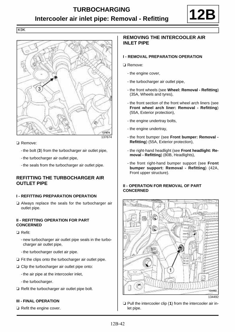
12B-42
TURBOCHARGINGIntercooler air inlet pipe: Removal - Refitting
K9K
12B
a Remove:
- the bolt (3) from the turbocharger air outlet pipe,
- the turbocharger air outlet pipe,
- the seals from the turbocharger air outlet pipe.
REFITTING THE TURBOCHARGER AIR OUTLET PIPE
I - REFITTING PREPARATION OPERATION
a Always replace the seals for the turbocharger airoutlet pipe.
II - REFITTING OPERATION FOR PART CONCERNED
a Refit:
- new turbocharger air outlet pipe seals in the turbo-charger air outlet pipe,
- the turbocharger outlet air pipe.
a Fit the clips onto the turbocharger air outlet pipe.
a Clip the turbocharger air outlet pipe onto:
- the air pipe at the intercooler inlet,
- the turbocharger.
a Refit the turbocharger air outlet pipe bolt.
III - FINAL OPERATION
a Refit the engine cover.
REMOVING THE INTERCOOLER AIR INLET PIPE
I - REMOVAL PREPARATION OPERATION
a Remove:
- the engine cover,
- the turbocharger air outlet pipe,
- the front wheels (see Wheel: Removal - Refitting)(35A, Wheels and tyres),
- the front section of the front wheel arch liners (seeFront wheel arch liner: Removal - Refitting)(55A, Exterior protection),
- the engine undertray bolts,
- the engine undertray,
- the front bumper (see Front bumper: Removal -Refitting) (55A, Exterior protection),
- the right-hand headlight (see Front headlight: Re-moval - Refitting) (80B, Headlights),
- the front right-hand bumper support (see Frontbumper support: Removal - Refitting) (42A,Front upper structure).
II - OPERATION FOR REMOVAL OF PART CONCERNED
a Pull the intercooler clip (1) from the intercooler air in-let pipe.
137674
134492
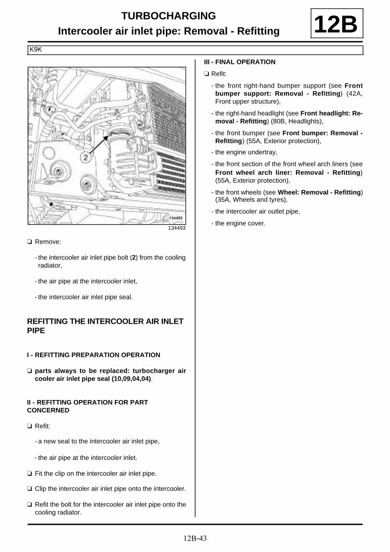
12B-43
TURBOCHARGINGIntercooler air inlet pipe: Removal - Refitting
K9K
12B
a Remove:
- the intercooler air inlet pipe bolt (2) from the coolingradiator,
- the air pipe at the intercooler inlet,
- the intercooler air inlet pipe seal.
REFITTING THE INTERCOOLER AIR INLET PIPE
I - REFITTING PREPARATION OPERATION
a parts always to be replaced: turbocharger aircooler air inlet pipe seal (10,09,04,04).
II - REFITTING OPERATION FOR PART CONCERNED
a Refit:
- a new seal to the intercooler air inlet pipe,
- the air pipe at the intercooler inlet.
a Fit the clip on the intercooler air inlet pipe.
a Clip the intercooler air inlet pipe onto the intercooler.
a Refit the bolt for the intercooler air inlet pipe onto thecooling radiator.
III - FINAL OPERATION
a Refit:
- the front right-hand bumper support (see Frontbumper support: Removal - Refitting) (42A,Front upper structure),
- the right-hand headlight (see Front headlight: Re-moval - Refitting) (80B, Headlights),
- the front bumper (see Front bumper: Removal -Refitting) (55A, Exterior protection),
- the engine undertray,
- the front section of the front wheel arch liners (seeFront wheel arch liner: Removal - Refitting)(55A, Exterior protection),
- the front wheels (see Wheel: Removal - Refitting)(35A, Wheels and tyres),
- the intercooler air outlet pipe,
- the engine cover.134493
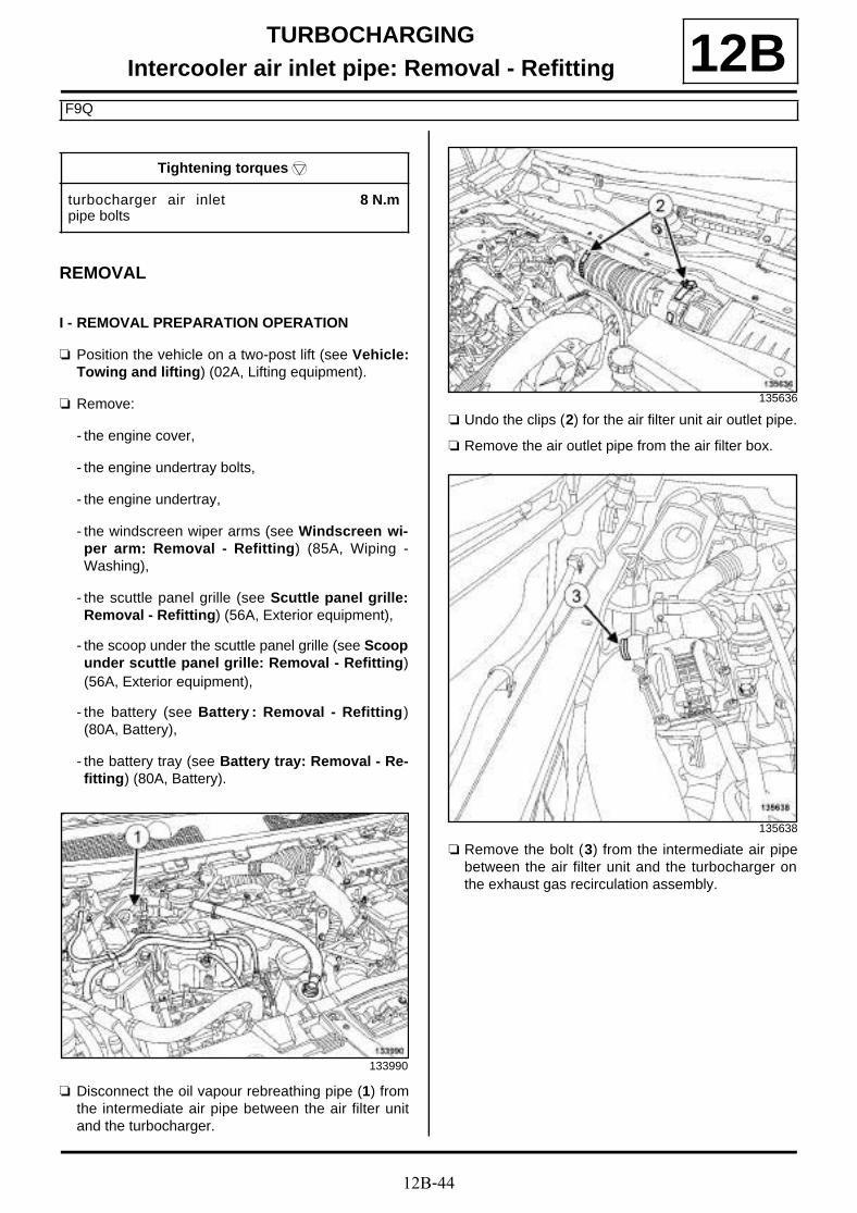
12B-44
TURBOCHARGINGIntercooler air inlet pipe: Removal - Refitting
F9Q
12B
REMOVAL
I - REMOVAL PREPARATION OPERATION
a Position the vehicle on a two-post lift (see Vehicle:Towing and lifting) (02A, Lifting equipment).
a Remove:
- the engine cover,
- the engine undertray bolts,
- the engine undertray,
- the windscreen wiper arms (see Windscreen wi-per arm: Removal - Refitting) (85A, Wiping -Washing),
- the scuttle panel grille (see Scuttle panel grille:Removal - Refitting) (56A, Exterior equipment),
- the scoop under the scuttle panel grille (see Scoopunder scuttle panel grille: Removal - Refitting)(56A, Exterior equipment),
- the battery (see Battery : Removal - Refitting)(80A, Battery),
- the battery tray (see Battery tray: Removal - Re-fitting) (80A, Battery).
a Disconnect the oil vapour rebreathing pipe (1) fromthe intermediate air pipe between the air filter unitand the turbocharger.
a Undo the clips (2) for the air filter unit air outlet pipe.
a Remove the air outlet pipe from the air filter box.
a Remove the bolt (3) from the intermediate air pipebetween the air filter unit and the turbocharger onthe exhaust gas recirculation assembly.
Tightening torquesm
turbocharger air inletpipe bolts
8 N.m
133990
135636
135638
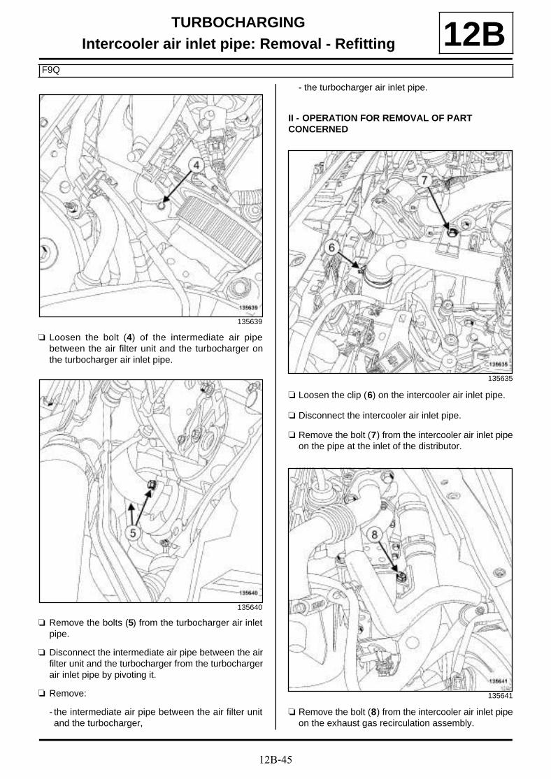
12B-45
TURBOCHARGINGIntercooler air inlet pipe: Removal - Refitting
F9Q
12B
a Loosen the bolt (4) of the intermediate air pipebetween the air filter unit and the turbocharger onthe turbocharger air inlet pipe.
a Remove the bolts (5) from the turbocharger air inletpipe.
a Disconnect the intermediate air pipe between the airfilter unit and the turbocharger from the turbochargerair inlet pipe by pivoting it.
a Remove:
- the intermediate air pipe between the air filter unitand the turbocharger,
- the turbocharger air inlet pipe.
II - OPERATION FOR REMOVAL OF PART CONCERNED
a Loosen the clip (6) on the intercooler air inlet pipe.
a Disconnect the intercooler air inlet pipe.
a Remove the bolt (7) from the intercooler air inlet pipeon the pipe at the inlet of the distributor.
a Remove the bolt (8) from the intercooler air inlet pipeon the exhaust gas recirculation assembly.
135639
135640
135635
135641
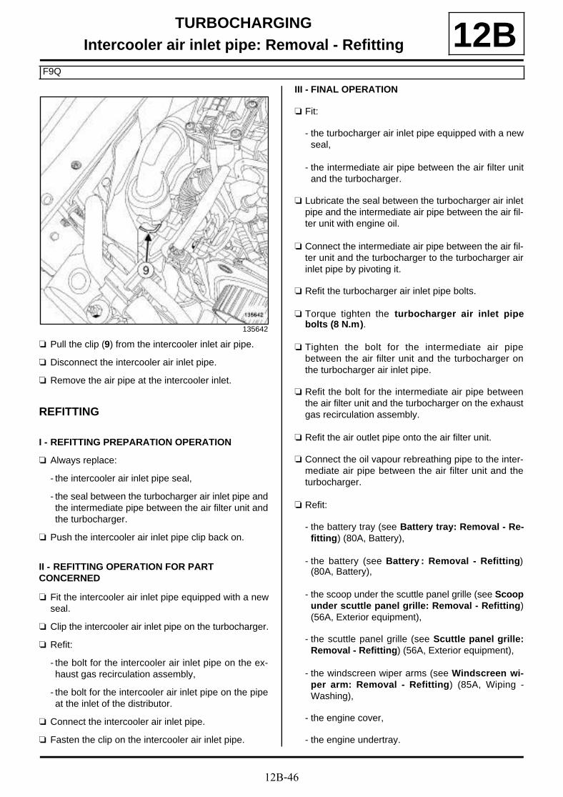
12B-46
TURBOCHARGINGIntercooler air inlet pipe: Removal - Refitting
F9Q
12B
a Pull the clip (9) from the intercooler inlet air pipe.
a Disconnect the intercooler air inlet pipe.
a Remove the air pipe at the intercooler inlet.
REFITTING
I - REFITTING PREPARATION OPERATION
a Always replace:
- the intercooler air inlet pipe seal,
- the seal between the turbocharger air inlet pipe andthe intermediate pipe between the air filter unit andthe turbocharger.
a Push the intercooler air inlet pipe clip back on.
II - REFITTING OPERATION FOR PART CONCERNED
a Fit the intercooler air inlet pipe equipped with a newseal.
a Clip the intercooler air inlet pipe on the turbocharger.
a Refit:
- the bolt for the intercooler air inlet pipe on the ex-haust gas recirculation assembly,
- the bolt for the intercooler air inlet pipe on the pipeat the inlet of the distributor.
a Connect the intercooler air inlet pipe.
a Fasten the clip on the intercooler air inlet pipe.
III - FINAL OPERATION
a Fit:
- the turbocharger air inlet pipe equipped with a newseal,
- the intermediate air pipe between the air filter unitand the turbocharger.
a Lubricate the seal between the turbocharger air inletpipe and the intermediate air pipe between the air fil-ter unit with engine oil.
a Connect the intermediate air pipe between the air fil-ter unit and the turbocharger to the turbocharger airinlet pipe by pivoting it.
a Refit the turbocharger air inlet pipe bolts.
a Torque tighten the turbocharger air inlet pipebolts (8 N.m).
a Tighten the bolt for the intermediate air pipebetween the air filter unit and the turbocharger onthe turbocharger air inlet pipe.
a Refit the bolt for the intermediate air pipe betweenthe air filter unit and the turbocharger on the exhaustgas recirculation assembly.
a Refit the air outlet pipe onto the air filter unit.
a Connect the oil vapour rebreathing pipe to the inter-mediate air pipe between the air filter unit and theturbocharger.
a Refit:
- the battery tray (see Battery tray: Removal - Re-fitting) (80A, Battery),
- the battery (see Battery : Removal - Refitting)(80A, Battery),
- the scoop under the scuttle panel grille (see Scoopunder scuttle panel grille: Removal - Refitting)(56A, Exterior equipment),
- the scuttle panel grille (see Scuttle panel grille:Removal - Refitting) (56A, Exterior equipment),
- the windscreen wiper arms (see Windscreen wi-per arm: Removal - Refitting) (85A, Wiping -Washing),
- the engine cover,
- the engine undertray.
135642

12B-47
TURBOCHARGINGIntercooler air inlet pipe: Removal - Refitting
F4R
12B
REMOVAL
I - REMOVAL PREPARATION OPERATION
a Position the vehicle on a two-post lift (see Vehicle:Towing and lifting) (02A, Lifting equipment).
a Remove:
- the engine cover,
- the battery cover,
- the petrol injection computer cover,
- the engine undertray bolts,
- the engine undertray,
- the front left-hand wheel (see Wheel: Removal -Refitting) (35A, Wheels and tyres),
- the front section of the front left-hand wheel archliner (see Front wheel arch liner: Removal - Re-fitting) (55A, Exterior protection).
II - OPERATION FOR REMOVAL OF PART CONCERNED
a Loosen the clip (1) on the intercooler air inlet pipe.
a Remove the air pipe bolts (2) at the intercooler inlet.
a Remove the clip (3) for the intercooler air inlet pipe.
a Remove:
- the air pipe at the intercooler inlet,
- the intercooler air inlet pipe seal.
Tightening torquesm
intercooler air inlet pipeclip
6 N.m
134647
138084
135794
12B-48
TURBOCHARGINGIntercooler air inlet pipe: Removal - Refitting
F4R
12BREFITTING
I - REFITTING PREPARATION OPERATION
a parts always to be replaced: turbocharger aircooler air inlet pipe seal (10,09,04,04).
II - REFITTING OPERATION FOR PART CONCERNED
a Fit the intercooler air inlet pipe equipped with a newseal.
a Clip the intercooler air inlet pipe onto the intercooler.
a Refit the bolts on the intercooler air inlet pipe.
a Connect the intercooler air inlet pipe on the turbo-charger.
a Torque tighten the intercooler air inlet pipe clip (6N.m).
III - FINAL OPERATION
a Refit:
- the front section of the front left-hand wheel archliner (see Front wheel arch liner: Removal - Re-fitting) (55A, Exterior protection),
- the front left-hand wheel (see Wheel: Removal -Refitting) (35A, Wheels and tyres),
- the engine undertray,
- the petrol injection computer cover,
- the battery cover,
- the engine cover.
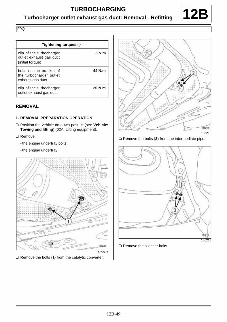
12B-49
TURBOCHARGINGTurbocharger outlet exhaust gas duct: Removal - Refitting
F9Q
12B
REMOVAL
I - REMOVAL PREPARATION OPERATION
a Position the vehicle on a two-post lift (see Vehicle:Towing and lifting) (02A, Lifting equipment).
a Remove:
- the engine undertray bolts,
- the engine undertray.
a Remove the bolts (1) from the catalytic converter.
a Remove the bolts (2) from the intermediate pipe.
a Remove the silencer bolts.
Tightening torquesm
clip of the turbochargeroutlet exhaust gas duct(initial torque)
5 N.m
bolts on the bracket ofthe turbocharger outletexhaust gas duct
44 N.m
clip of the turbochargeroutlet exhaust gas duct
20 N.m
135633
136212
136213
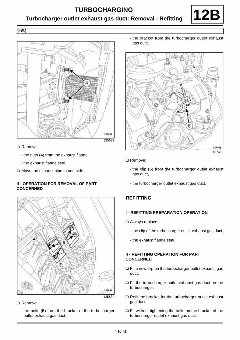
12B-50
TURBOCHARGINGTurbocharger outlet exhaust gas duct: Removal - Refitting
F9Q
12B
a Remove:
- the nuts (4) from the exhaust flange,
- the exhaust flange seal.
a Move the exhaust pipe to one side.
II - OPERATION FOR REMOVAL OF PART CONCERNED
a Remove:
- the bolts (5) from the bracket of the turbochargeroutlet exhaust gas duct,
- the bracket from the turbocharger outlet exhaustgas duct.
a Remove:
- the clip (6) from the turbocharger outlet exhaustgas duct,
- the turbocharger outlet exhaust gas duct.
REFITTING
I - REFITTING PREPARATION OPERATION
a Always replace:
- the clip of the turbocharger outlet exhaust gas duct,
- the exhaust flange seal.
II - REFITTING OPERATION FOR PART CONCERNED
a Fit a new clip on the turbocharger outlet exhaust gasduct.
a Fit the turbocharger outlet exhaust gas duct on theturbocharger.
a Refit the bracket for the turbocharger outlet exhaustgas duct.
a Fit without tightening the bolts on the bracket of theturbocharger outlet exhaust gas duct.
135632
135634
137465
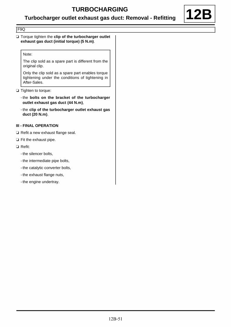
12B-51
TURBOCHARGINGTurbocharger outlet exhaust gas duct: Removal - Refitting
F9Q
12Ba Torque tighten the clip of the turbocharger outlet
exhaust gas duct (initial torque) (5 N.m).
a Tighten to torque:
- the bolts on the bracket of the turbochargeroutlet exhaust gas duct (44 N.m),
- the clip of the turbocharger outlet exhaust gasduct (20 N.m).
III - FINAL OPERATION
a Refit a new exhaust flange seal.
a Fit the exhaust pipe.
a Refit:
- the silencer bolts,
- the intermediate pipe bolts,
- the catalytic converter bolts,
- the exhaust flange nuts,
- the engine undertray.
Note:
The clip sold as a spare part is different from theoriginal clip.
Only the clip sold as a spare part enables torquetightening under the conditions of tightening inAfter-Sales.

12B-52
TURBOCHARGINGTurbocharger outlet exhaust gas duct: Removal - Refitting
K9K, and 836
12B
REMOVAL
I - REMOVAL PREPARATION OPERATION
a Position the vehicle on a two-post lift (see Vehicle:Towing and lifting) (02A, Lifting equipment).
a Remove:
- the engine cover,
- the engine undertray bolts,
- the engine undertray.
a Undo:
- the air filter unit air outlet pipe clip (1) on the air fil-ter unit,
- the air filter unit air outlet pipe clip (2) on the turbo-charger air inlet pipe.
a Remove the air filter unit air outlet pipe.
a Unclip the turbocharging pressure regulation sole-noid valve hose from the turbocharger air inlet pipeat (3) .
Tightening torquesm
turbocharger outletexhaust gas duct bolts
XX N.m
exhaust bracket bolts XX Nm
exhaust fuel injectorcooler bolts
XX N.m
turbocharger outletexhaust gas duct staybolts
XX N.m
IMPORTANTWear protective gloves during the operation.
IMPORTANT
Wear leaktight gloves (Nitrile type) for this opera-tion.
100000-1
100000-1

12B-53
TURBOCHARGINGTurbocharger outlet exhaust gas duct: Removal - Refitting
K9K, and 836
12B
a Remove the turbocharger air inlet pipe bolt from theexhaust gas recirculation assembly (4) .
a Disconnect the oil vapour rebreathing pipe from therocker cover (5) .
a Remove:
- the turbocharger air inlet pipe bolts (6) from the tur-bocharger,
- the turbocharger air inlet pipe.
a Remove:
- the bolts (7) from the bracket of the turbochargeroutlet exhaust gas duct,
- the bracket from the turbocharger outlet exhaustgas duct.
100000-1
100000-1
100000-1
100000-1

12B-54
TURBOCHARGINGTurbocharger outlet exhaust gas duct: Removal - Refitting
K9K, and 836
12B
a Disconnect:
- the exhaust fuel injector connector (8) ,
- the exhaust fuel injector fuel supply pipe union fromthe exhaust fuel injector (9) .
a Fit blanking plugs on:
- the fuel supply pipe opening of the exhaust fuel in-jector,
- the exhaust fuel injector opening.
a Remove:
- the bolts (10) from the exhaust fuel injector cooler,
- the exhaust fuel injector cooler,
- the heat shield from the turbocharger.
a Remove the bolts (11) from the exhaust bracket.
a Move the exhaust pipe to one side.
II - OPERATION FOR REMOVAL OF PART CONCERNED
a Remove:
- the bolts (12) from the turbocharger outlet exhaustgas duct,
- the exhaust gases duct at the turbocharger outlet,
- the seal from the turbocharger outlet exhaust gasduct.
100000-1 100000-1
100000-1

12B-55
TURBOCHARGINGTurbocharger outlet exhaust gas duct: Removal - Refitting
K9K, and 836
12BREFITTING
I - REFITTING PREPARATION OPERATION
a parts always to be replaced: Turbocharger heatshield (10,09,01,02).
a Always replace the seal of the turbocharger outletexhaust gas duct.
a Always replace the exhaust bracket seal.
a Use ABRASIVE PADS to clean the joint face:
- on the turbocharger,
- on the turbocharger outlet exhaust gas duct on theturbocharger side if reusing,
- on the turbocharger outlet exhaust gas duct on theexhaust pipe side if reusing,
- on the turbocharger outlet exhaust gas duct on theexhaust fuel injector cooler side if reusing,
- on the exhaust fuel injector cooler.
a Use SURFACE CLEANER (see Vehicle: Parts and ingredients for the repairwork) (04B, Consu-mables - Products) and CLEAN CLOTHS to de-grease the joint face:
- on the turbocharger,
- on the turbocharger outlet exhaust gas duct on theturbocharger side if reusing,
- on the turbocharger outlet exhaust gas duct on theexhaust pipe side if reusing,
- on the turbocharger outlet exhaust gas duct on theexhaust fuel injector cooler side if reusing,
- on the exhaust fuel injector cooler.
II - REFITTING OPERATION FOR PART CONCERNED
a Refit the turbocharger outlet exhaust gas duct fittedwith a new seal on the turbocharger.
a Torque tighten the turbocharger outlet exhaustgas duct bolts (XX N.m).
III - FINAL OPERATION
a Refit:
- a new exhaust bracket seal,
- the exhaust bracket bolts.
a Torque tighten the exhaust bracket bolts (XX Nm).
a Refit:
- a new turbocharger heat shield,
- the exhaust fuel injector cooler.
a Torque tighten the exhaust fuel injector coolerbolts (XX N.m).
a Remove the blanking plug:
- from the exhaust fuel injector opening,
- from the fuel supply pipe opening of the exhaustfuel injector.
a Connect:
- the fuel supply pipe union of the exhaust fuel injec-tor to the exhaust fuel injector,
- the exhaust fuel injector connector.
a Refit the bracket for the turbocharger outlet exhaustgas duct.
a Torque tighten the turbocharger outlet exhaustgas duct stay bolts (XX N.m).
a Refit the turbocharger air inlet pipe.
a Connect the oil vapour rebreathing pipe onto therocker cover.
a Refit the turbocharger air inlet pipe bolt onto the ex-haust gas recirculation assembly.
a Clip the turbocharging pressure regulation solenoidvalve hose onto the turbocharger air inlet pipe.
a Refit the air outlet pipe onto the air filter unit.
a Tighten the clip of the air filter unit air outlet pipe on:
- the turbocharger air inlet pipe,
- the air filter unit.
a Refit:
- the engine undertray,
- the engine cover.

12B-56
TURBOCHARGINGIntercooler air outlet pipe: Removal - Refitting
K9K
12B
REMOVAL
I - REMOVAL PREPARATION OPERATION
a Remove:
- the engine cover,
- the engine undertray bolts,
- the engine undertray.
II - OPERATION FOR REMOVAL OF PART CONCERNED
a Pull the intercooler clip (1) from the intercooler airoutlet pipe.
a Remove the nut (2) from the bracket of the intercoo-ler air outlet pipe.
a Disconnect the turbocharger pressure sensor con-nector (3) .
a Unclip the turbocharging pressure sensor wiring (4)from the intercooler air outlet pipe.
a Loosen the damper valve clip (5) from the intercoo-ler air outlet pipe.
a Disconnect the intercooler air outlet pipe from thedamper valve.
a Remove the intercooler air outlet pipe.
Tightening torquesm
intercooler air outletpipe clip on the dampervalve
5.5 N.m
135465
135406
134215
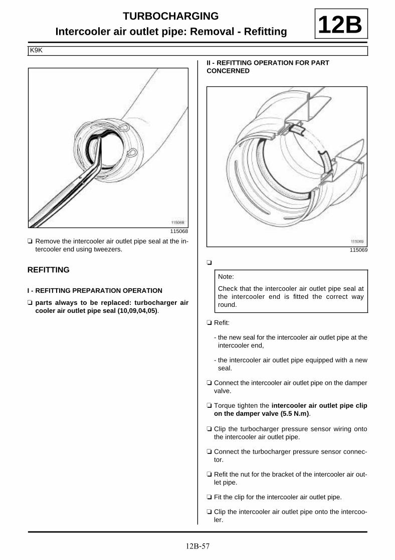
12B-57
TURBOCHARGINGIntercooler air outlet pipe: Removal - Refitting
K9K
12B
a Remove the intercooler air outlet pipe seal at the in-tercooler end using tweezers.
REFITTING
I - REFITTING PREPARATION OPERATION
a parts always to be replaced: turbocharger aircooler air outlet pipe seal (10,09,04,05).
II - REFITTING OPERATION FOR PART CONCERNED
a
a Refit:
- the new seal for the intercooler air outlet pipe at theintercooler end,
- the intercooler air outlet pipe equipped with a newseal.
a Connect the intercooler air outlet pipe on the dampervalve.
a Torque tighten the intercooler air outlet pipe clipon the damper valve (5.5 N.m).
a Clip the turbocharger pressure sensor wiring ontothe intercooler air outlet pipe.
a Connect the turbocharger pressure sensor connec-tor.
a Refit the nut for the bracket of the intercooler air out-let pipe.
a Fit the clip for the intercooler air outlet pipe.
a Clip the intercooler air outlet pipe onto the intercoo-ler.
115068
115069
Note:
Check that the intercooler air outlet pipe seal atthe intercooler end is fitted the correct wayround.
12B-58
TURBOCHARGINGIntercooler air outlet pipe: Removal - Refitting
K9K
12BIII - FINAL OPERATION
a Refit:
- the engine undertray,
- the engine cover.
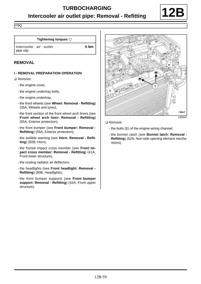
12B-59
TURBOCHARGINGIntercooler air outlet pipe: Removal - Refitting
F9Q
12B
REMOVAL
I - REMOVAL PREPARATION OPERATION
a Remove:
- the engine cover,
- the engine undertray bolts,
- the engine undertray,
- the front wheels (see Wheel: Removal - Refitting)(35A, Wheels and tyres),
- the front section of the front wheel arch liners (seeFront wheel arch liner: Removal - Refitting)(55A, Exterior protection),
- the front bumper (see Front bumper: Removal -Refitting) (55A, Exterior protection),
- the audible warning (see Horn: Removal - Refit-ting) (82B, Horn),
- the frontal impact cross member (see Front im-pact cross member: Removal - Refitting) (41A,Front lower structure),
- the cooling radiator air deflectors,
- the headlights (see Front headlight: Removal -Refitting) (80B, Headlights),
- the front bumper supports (see Front bumpersupport: Removal - Refitting) (42A, Front upperstructure).
a Remove:
- the bolts (1) of the engine wiring channel,
- the bonnet catch (see Bonnet latch: Removal -Refitting) (52A, Non-side opening element mecha-nisms).
Tightening torquesm
intercooler air outletpipe clip
6 Nm
135647

12B-60
TURBOCHARGINGIntercooler air outlet pipe: Removal - Refitting
F9Q
12B
a Remove the front end panel bolts (2) .
a Tilt the front end panel.
II - OPERATION FOR REMOVAL OF PART CONCERNED
a Undo the clip (3) of the intercooler air outlet pipe onthe damper valve.
a Disconnect the intercooler air outlet pipe from thedamper valve.
a Remove the bolts (4) from the intercooler air outletpipe.
a Pull the clip (5) from the intercooler air outlet pipe onthe intercooler.
a Disconnect the intercooler air outlet pipe from the in-tercooler.
135645
135646
135648
135649

12B-61
TURBOCHARGINGIntercooler air outlet pipe: Removal - Refitting
F9Q
12Ba Remove the intercooler air outlet pipe.
REFITTING
I - REFITTING PREPARATION OPERATION
a parts always to be replaced: Intercooler air out-let pipe (10,09,04,03).
II - REFITTING OPERATION FOR PART CONCERNED
a Fit an air pipe to the outlet of the new intercooler.
a Clip the intercooler air outlet pipe onto the intercoo-ler.
a Refit the bolt for the intercooler air outlet pipe.
a Connect the intercooler air outlet pipe on the dampervalve.
a Torque tighten the intercooler air outlet pipe clip(6 Nm).
III - FINAL OPERATION
a Fit the front panel.
a Refit:
- the front end panel bolts,
- the bonnet catch (see Bonnet latch: Removal -Refitting) (52A, Non-side opening element mecha-nisms),
- the engine wiring channel bolts,
- the front bumper supports (see Front bumpersupport: Removal - Refitting) (42A, Front upperstructure),
- the headlights (see Front headlight: Removal -Refitting) (80B, Headlights),
- the cooling radiator air deflectors,
- the frontal impact cross member (see Front im-pact cross member: Removal - Refitting) (41A,Front lower structure),
- the audible warning (see Horn: Removal - Refit-ting) (82B, Horn),
- the front bumper (see Front bumper: Removal -Refitting) (55A, Exterior protection),
- the front section of the front wheel arch liners (seeFront wheel arch liner: Removal - Refitting)(55A, Exterior protection),
- the front wheels (see Wheel: Removal - Refitting)(35A, Wheels and tyres),
- the engine undertray,
- the engine cover.

12B-62
TURBOCHARGINGIntercooler air outlet pipe: Removal - Refitting
F4R
12BREMOVAL
I - REMOVAL PREPARATION OPERATION
a Position the vehicle on a two-post lift (see Vehicle:Towing and lifting) (02A, Lifting equipment).
a Remove:
- the engine cover,
- the petrol injection computer cover,
- the engine undertray bolts,
- the engine undertray,
- the front wheels (see Wheel: Removal - Refitting)(35A, Wheels and tyres),
- the front section of the front wheel arch liners (seeFront wheel arch liner: Removal - Refitting)(55A, Exterior protection),
- the front bumper (see Front bumper: Removal -Refitting) (55A, Exterior protection),
- the upper air deflector,
- the side air deflectors,
- the headlights (see Front headlight: Removal -Refitting) (80B, Headlights),
- the front bumper supports (see Front bumpersupport: Removal - Refitting) (42A, Front upperstructure),
- the frontal impact cross member (see Front im-pact cross member: Removal - Refitting) (41A,Front lower structure),
- the bonnet catch (see Bonnet latch: Removal -Refitting) (52A, Non-side opening element mecha-nisms).
a Remove the bolts (1) from the engine wiring harnesschannel.
a Remove:
- the upper bolts (2) from the front end panel,
- the front panel clips (3) .
135736
135719

12B-63
TURBOCHARGINGIntercooler air outlet pipe: Removal - Refitting
F4R
12B
a Remove the lower bolts (4) from the front end panel.
a Slightly tilt the front panel towards the front of the ve-hicle.
II - OPERATION FOR REMOVAL OF PART CONCERNED
a Remove the bolt (5) from the intercooler air outlet pi-pe.
a Disconnect:
- the turbocharger pressure sensor connector (6) ,
- the air temperature sensor connector (7) .
a Remove the intercooler outlet pipe bolts (8) from thethrottle unit.
a Remove the bolt (9) from the intercooler air outlet pi-pe.
135296
135793
135796
135795

12B-64
TURBOCHARGINGIntercooler air outlet pipe: Removal - Refitting
F4R
12B
a Move aside the clip (10) for the intercooler air outletpipe.
a Remove:
- the intercooler air outlet pipe,
- the intercooler air outlet pipe seals.
REFITTING
I - REFITTING PREPARATION OPERATION
a parts always to be replaced: turbocharger aircooler air outlet pipe seal (10,09,04,05).
II - REFITTING OPERATION FOR PART CONCERNED
a Fit the intercooler air outlet pipe equipped with a newseal.
a Clip the intercooler air outlet pipe onto the intercoo-ler.
a Refit the bolts for the intercooler air outlet pipe.
a Connect:
- the air temperature sensor connector,
- the turbocharging pressure sensor connector.
III - FINAL OPERATION
a Refit:
- the lower bolts from the front end panel,
- the front end panel upper bolts,
- the engine wiring channel bolts,
- the bonnet catch (see Bonnet latch: Removal -Refitting) (52A, Non-side opening element mecha-nisms),
- the frontal impact cross member (see Front im-pact cross member: Removal - Refitting) (41A,Front lower structure),
- the front bumper supports (see Front bumpersupport: Removal - Refitting) (42A, Front upperstructure),
- the headlights (see Front headlight: Removal -Refitting) (80B, Headlights),
- the side air deflectors,
- the upper air deflector,
- the front bumper (see Front bumper: Removal -Refitting) (55A, Exterior protection),
- the front section of the front wheel arch liners (seeFront wheel arch liner: Removal - Refitting)(55A, Exterior protection),
- the front wheels (see Wheel: Removal - Refitting)(35A, Wheels and tyres),
- the engine undertray,
- the petrol injection computer cover,
- the engine cover.
135797

13A-1
FUEL SUPPLYManual priming pump: Removal - Refitting
F9Q or K9K
13AREMOVAL
OPERATION FOR REMOVAL OF PART CONCERNED
a Disconnect from the manual priming pump:
- the fuel supply pipe union (1) from the fuel filter out-let,
- the fuel supply pipe union (2) at the inlet of the highpressure pump.
a Fit the correct blanking plugs on:
- the fuel supply pipe opening at the outlet of the fuelfilter,
- the fuel supply pipe opening at the inlet of the highpressure pump,
- the openings of the manual priming pump.
IMPORTANT
To avoid all risk of damage to the systems, applythe safety and cleanliness instructions and opera-tion recommendations before carrying out anyrepair (see 13B, Diesel injection, Diesel injec-tion: Precautions for repair, page 13B-1) .
WARNING
To avoid any corrosion or damage, protect theareas on which fuel is likely to run.
WARNING
To prevent impurities from entering the circuit, placeprotective plugs on all fuel circuit componentsexposed to the open air.
WARNING
Keep the pipe unions away from contaminatedareas.
136606
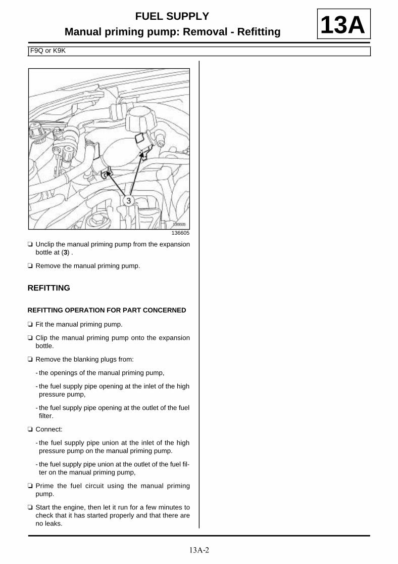
13A-2
FUEL SUPPLYManual priming pump: Removal - Refitting
F9Q or K9K
13A
a Unclip the manual priming pump from the expansionbottle at (3) .
a Remove the manual priming pump.
REFITTING
REFITTING OPERATION FOR PART CONCERNED
a Fit the manual priming pump.
a Clip the manual priming pump onto the expansionbottle.
a Remove the blanking plugs from:
- the openings of the manual priming pump,
- the fuel supply pipe opening at the inlet of the highpressure pump,
- the fuel supply pipe opening at the outlet of the fuelfilter.
a Connect:
- the fuel supply pipe union at the inlet of the highpressure pump on the manual priming pump.
- the fuel supply pipe union at the outlet of the fuel fil-ter on the manual priming pump,
a Prime the fuel circuit using the manual primingpump.
a Start the engine, then let it run for a few minutes tocheck that it has started properly and that there areno leaks.
136605

13A-3
FUEL SUPPLYFuel filter: Removal - Refitting
F9Q or K9K
13A
REMOVAL
I - REMOVAL PREPARATION OPERATION
a Position the vehicle on a two-post lift (see Vehicle:Towing and lifting) (02A, Lifting equipment).
a Remove:
- the front right-hand wheel (see Wheel: Removal -Refitting) (35A, Wheels and tyres),
- the front section of the front right-hand wheel archliner (see Front wheel arch liner: Removal - Re-fitting) (55A, Exterior protection).
II - REMOVAL OF PART CONCERNED
a Disconnect the diesel fuel heater connector (1) .
a Remove the fuel filter mounting nut (2) .
a Disconnect the fuel pipes (3) on the fuel filter
a Fit blanking plugs.
a Remove the fuel filter.
REFITTING
I - REFITTING PREPARATION OPERATION
a parts always to be replaced: fuel filter seal (11,03,01,07).
II - REFITTING OPERATION FOR PART CONCERNED
a Refit the fuel filter onto the mounting.
a Connect the fuel supply pipes.
a Refit the fuel filter mounting nut.
a Connect the diesel fuel heater connector.
IMPORTANT
Consult the safety and cleanliness advice and ope-ration recommendations before carrying out anyrepair (see 13B, Diesel injection, Diesel injec-tion: Precautions for repair, page 13B-1) .
WARNINGTo avoid any corrosion or damage, protect theareas on which fuel is likely to run.
133985
WARNING
Keep the pipe unions away from contaminatedareas.
Note:
If the fuel filter is to be re-used, fit blanking plugs.

13A-4
FUEL SUPPLYFuel filter: Removal - Refitting
F9Q or K9K
13ABleeding the circuit
a Fit a pipe to the injector rail fuel supply union.
a Push the pipe onto the injector rail fuel supply union.
a Prime the fuel supply circuit using the manual primi-ng pump until fuel runs into the container.
III - DRAINING THE WATER INSIDE THE FUEL FILTER
a Periodically drain any water contained inside the fuelfilter.
a For filters without a water presence sensor:
- open the drain plug,
- let the water flow out,
- close the plug.
a For filters with a water presence sensor:
- disconnect the water presence sensor offset con-nector,
- unclip the water presense sensor connector,
- loosen the water presence sensor by one turn,
- let the water flow out,
- tighten the water presence sensor.
IV - FINAL OPERATION
a Check that there are no fuel leaks.
a Refit:
- the front section of the front right-hand wheel archliner (see Front wheel arch liner: Removal - Re-fitting) (55A, Exterior protection),
- the front right-hand wheel (see Wheel: Removal -Refitting) (35A, Wheels and tyres).

13A-5
FUEL SUPPLYFuel filter: Removal - Refitting
F4R or K4M
13A
REMOVAL
a The fuel filter is located in the tank and integratedinto the « pump - sender - filter » assembly. To re-move the fuel filter, remove the « pump - sender - fil-ter assembly » (see 19C, Tank, Fuel level sensormodule: Removal - Refitting, page 19C-16) .
I - REMOVAL PREPARATION OPERATION
a Position the vehicle on a two-post lift (see Vehicle:Towing and lifting) (02A, Lifting equipment).
a Disconnect the battery (see Battery: Removal - Re-fitting) (80A, Battery).
II - OPERATION FOR REMOVAL OF PART CONCERNED
a Disconnect the fuel filter unions (1) .
a Insert the blanking plugs.
IMPORTANT
During this operation, be sure to:
- refrain from smoking or bringing red hot objectsclose to the working area,
- be careful of fuel splashes when disconnecting theunion.
IMPORTANT
Wear goggles with side protectors for this opera-tion.
IMPORTANT
Wear leaktight gloves (Nitrile type) for this opera-tion.
WARNING
To prevent impurities from entering the circuit, placeprotective plugs on all fuel circuit componentsexposed to the open air.
WARNING
To avoid any corrosion or damage, protect theareas on which fuel is likely to run.
K4M
F4R
F4R
132674

13A-6
FUEL SUPPLYFuel filter: Removal - Refitting
F4R or K4M
13A
a Unclip (2) the fuel filter at (3) .
a Remove the fuel filter from the fuel tank.
REFITTING
I - REFITTING OPERATION FOR PART CONCERNED
a Refit the fuel filter.
a Clip on the fuel filter.
a Remove the blanking plugs.
a Connect the unions to the fuel filter.
II - FINAL OPERATION
a Connect the battery (see Battery: Removal - Refit-ting) (80A, Battery).
132676
F4R
F4R

13A-7
FUEL SUPPLYFuel pressure: check
F4R or K4M
13ACHECKING
I - PREPARATION OPERATION FOR CHECK
a Ensure you have a checking tool (Mot. 1311-01) anda « T » union (Mot. 1311-08).
a Remove the front engine cover.
Essential special tooling
Mot. 1311-01 Fuel pressure test kit.
Mot. 1311-08 Union for measuring fuelpressure.
IMPORTANT
During this operation, be sure to:
- refrain from smoking or bringing red hot objectsclose to the working area,
- be careful of fuel splashes when disconnecting theunion.
IMPORTANT
Wear goggles with side protectors for this opera-tion.
IMPORTANT
Wear leaktight gloves (Nitrile type) for this opera-tion.
WARNING
To avoid any corrosion or damage, protect theareas on which fuel is likely to run.
116887

13A-8
FUEL SUPPLYFuel pressure: check
F4R or K4M
13AII - TEST OPERATION
a Disconnect fuel supply pipe union on the injector rail.
a Connect:
- the pipe fitted with a test pressure gauge (Mot.1311-01) (1) , with the « T » union (Mot. 1311-08)(2) ,
- the « T » union to the injector rail,
- the injector rail fuel supply union to the « T » union(Mot. 1311-08) (Mot. 1311-08).
a Disconnect fuel supply pipe union on the injector rail.
a Unclip the fuel pipe from the right-hand suspendedengine mounting.
a Connect:
- the pipe fitted with a test pressure gauge (Mot.1311-01) (1) , with the « T » union (Mot. 1311-08)(2) ,
- the « T » union (Mot. 1311-08) to the injector rail,
- the injector rail fuel supply union to the « T » union(Mot. 1311-08).
a Start the engine.
a Record the pressure; this should be constant at 3.5bar.
a Switch off the engine.
a Start the engine.
a Record the pressure; this should be constant at 3.5bar.
a Switch off the engine.
F4R
137773
K4M
137774
Note:
It may take a few seconds to obtain a correctinjector rail pressure reading.

13A-9
FUEL SUPPLYFuel pressure: check
F4R or K4M
13AIII - FINAL OPERATION
a Disconnect the « T » union (Mot. 1311-08) from theinjector rail.
a Separate the test tool (Mot. 1311-01) from the « T »union.
a Connect the fuel supply pipe union on the injectorrail.
a Clip the fuel pipe on the right-hand suspended engi-ne mounting.
a Refit the engine cover.
K4M or M4R

13A-10
FUEL SUPPLYFuel flow: check
F4R or K4M
13A
I - PREPARATION OPERATION FOR CHECK
a Remove the front engine cover.
a Ensure you have a checking tool (Mot. 1311-01) anda « T » union (Mot. 1311-08).
a Assemble the long hose of the checking tool (Mot.1311-01) and the « T » union (Mot. 1311-08).
a Disconnect the fuel supply union on the injector rail.
a Connect:
- the « T » union (Mot. 1311-08) (1) to the injectorrail,
- the fuel supply union to the « T » union (Mot. 1311-08)
Essential special tooling
Mot. 1311-01 Fuel pressure test kit.
Mot. 1311-08 Union for measuring fuelpressure.
Essential equipment
graduated measuring cylinder
IMPORTANT
During this operation, be sure to:
- refrain from smoking or bringing red hot objectsclose to the working area,
- be careful of fuel splashes when disconnecting theunion.
IMPORTANT
Wear leaktight gloves (Nitrile type) for this opera-tion.
IMPORTANT
Wear goggles with side protectors for this opera-tion.
WARNING
To avoid any corrosion or damage, protect theareas on which fuel is likely to run.
F4R
137772

13A-11
FUEL SUPPLYFuel flow: check
F4R or K4M
13A
a Unclip the fuel pipe from the right-hand suspendedengine mounting.
a Connect:
- the « T » union (Mot. 1311-08) (1) to the injectorrail,
- the fuel supply union to the « T » union (Mot. 1311-08).
a Unclip the fuel pipe from the right-hand suspendedengine mounting.
a Disconnect the fuel supply union on the injector rail.
a Connect:
- the « T » union (Mot. 1311-08) (1) to the injectorrail,
- the fuel supply union to the « T » union (Mot. 1311-08).
II - FUEL FLOW CHECK
a Immerse the hose in a 2000 ml graduated measu-ring cylinder.
a Unclip the Protection and Switching Unit cover.
K4M
137771
M4R
138709
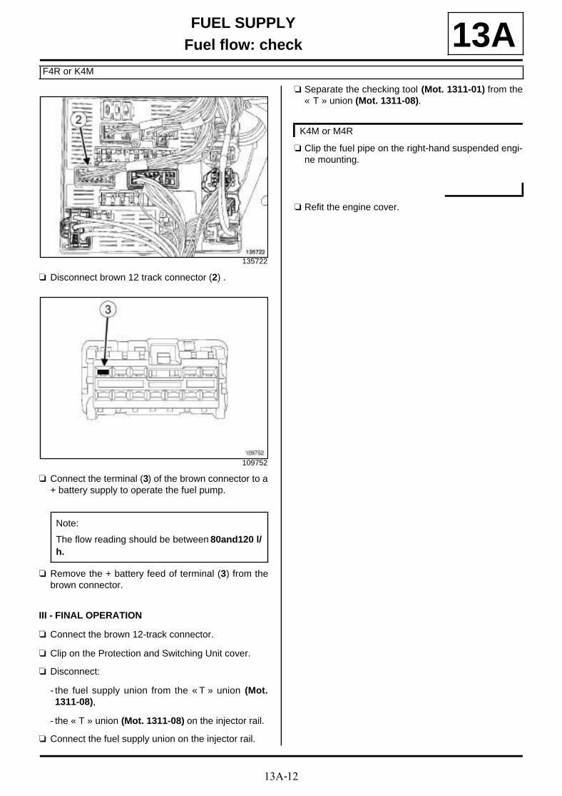
13A-12
FUEL SUPPLYFuel flow: check
F4R or K4M
13A
a Disconnect brown 12 track connector (2) .
a Connect the terminal (3) of the brown connector to a+ battery supply to operate the fuel pump.
a Remove the + battery feed of terminal (3) from thebrown connector.
III - FINAL OPERATION
a Connect the brown 12-track connector.
a Clip on the Protection and Switching Unit cover.
a Disconnect:
- the fuel supply union from the « T » union (Mot.1311-08),
- the « T » union (Mot. 1311-08) on the injector rail.
a Connect the fuel supply union on the injector rail.
a Separate the checking tool (Mot. 1311-01) from the« T » union (Mot. 1311-08).
a Clip the fuel pipe on the right-hand suspended engi-ne mounting.
a Refit the engine cover.
135722
109752
Note:
The flow reading should be between 80and120 l/h.
K4M or M4R

13B-1
DIESEL INJECTIONDiesel injection: Precautions for repair
F9Q or K9K
13BI - RISKS RELATING TO CONTAMINATION
The high-pressure direct injection system is highly sen-sitive to contamination. The risks caused by contami-nation are:
- damage to or destruction of the high pressure injec-tion system,
- a component seizing,
- a component not being properly sealed.
All After-Sales operations must be performed undervery clean conditions. Having carried out an operationin good conditions means that no impurities (particles afew microns in size) have penetrated the system duringdismantling.
The cleanliness principle must be applied from the filterto the injectors.
What are the sources of contamination?
- metal or plastic swarf,
- paint,
- fibres:
• cardboard,
• brushes,
• paper,
• clothing,
• cloth,
- foreign bodies such as hair,
- ambient air,
- etc.
1 - Cleaning cloths
Use lint free cleaning cloths (see Vehicle: Parts andingredients for the repairwork) .
The use of rags or ordinary paper towels is prohibited:these produce lint and lose fibres, which then contami-nate the fuel circuit.
Each cloth must only be used once.
2 - Blanking plugs
The blanking plugs are used to cap the fuel circuit onceit is opened and to therefore prevent contaminantsfrom entering.
A set of blanking plugs should be used once only andused plugs must be discarded: once used, the plugsare soiled and cleaning them is not sufficient to makethem reusable.
Unused plugs must also be discarded and must not beused when carrying out work on an injection system.
Part number for set of blanking plugs: (see Vehicle:Parts and ingredients for the repairwork) (04B, Con-sumables - Products)
3 - Protective bags
Use hermetically-resealable plastic bags, using adhe-sive tape, for example, to store components which willbe refitted and reused. Stored parts will therefore beless subject to the risk of contamination.
These are single-use bags: after use they must be dis-carded.
4 - Cleaning products
Two cleaning products can be used:
- an injector cleaner (see Vehicle: Parts and ingre-dients for the repairwork) (04B, Consumables -Products),
- an aerosol spray brake cleaner (see Vehicle: Partsand ingredients for the repairwork) (04B, Consu-mables - Products).
To use the injector cleaner, be sure to have a cleanbrush in good condition (the brush must not lose anybristles) as well as a clean container which has no im-purities in it.
WARNING
Do not clean the engine with a high pressure clea-ner to prevent damaging the connections.
Note:
There is no specific set of blanking plugs for S9Uand S9W engines. In order to comply with thecleanliness recommendations, use plugs that arecompatible with the blanking plug sets for F9Q,G9U, G9T or ZD3 engines.
Note:
Use a new injector cleaner each time work is car-ried out (a used cleaning agent will contain impuri-ties).

13B-2
DIESEL INJECTIONDiesel injection: Precautions for repair
F9Q or K9K
13BII - ADVICE TO BE FOLLOWED BEFORE ANY OPERATION
1) Carry out the work in a clean working area and takecare to protect removed components from dust usingplastic bags which are hermetically-resealable, forexample.
2) Always order the following from the Parts Depart-ment before carrying out work:
- a new set of blanking plugs, specific to the engine,
- enough lint-free cleaning cloths.
- one of the two cleaning products for fuel pipeunions,
- the parts that are always to be replaced after eachremoval operation, mentioned in the operational pro-cedures specific to the vehicle (see related WorkshopRepair Manual).
3) Wear safety goggles fitted with side shields to pre-vent the cleaning product from splashing the eyes.
4) Wear leaktight protective gloves (Nitrile type) toavoid prolonged contact with the skin.
5) Before carrying out work on the injection system, use plastic bags or clean cloths, for example, to pro-tect:
- the accessories and timing belts,
- the electrical accessories (starter, alternator, power-assisted steering pump, sensors and electrical con-nectors),
- the flywheel face.
III - INSTRUCTIONS TO BE FOLLOWED DURING THE OPERATION
Wash your hands before and while carrying out thework.
Replace leaktight protective gloves (Nitrile type) whenthey are soiled or damaged.
All components removed from the injection systemmust be stored in a hermetically sealed plastic bagonce they have been capped.
Reseal the bag hermetically, for example using adhesi-ve tape, even if the bag must be opened shortly afte-rwards: ambient air can be a source of impurities.
After opening the fuel circuit, the use of brushes, clea-ning agents, air blow guns, rifle-type brushes or stan-dard cloths is strictly prohibited: These items are likelyto allow impurities to enter the system.
When replacing a component with a new one or whenrefitting it after storing it in a plastic bag, do not unpackit until it is time to fit it on the vehicle.
IV - CLEANING
There are currently two procedures for cleaning thefuel circuit before opening it in order to carry out work inthe workshop.
These procedures enable the fuel circuit to be cleanedto prevent contamination from entering: they both havethe same end result and neither is preferred over theother.
1 - Cleaning using injector cleaner
Clear the access to the unions that need opening, fol-lowing the work procedures specific to the vehicle (seethe relevant Workshop Repair Manual).
Protect sections which are sensitive to fuel leaks.
Pour the injector cleaning agent into a container whichis free from impurities.
Dip a clean brush, which is not shedding bristles, intothe container of injector cleaning agent.
Clean the unions carefully using the brush and the in-jector cleaning agent.
Blast the components that have been cleaned withcompressed air (tools, workbench, and also parts,unions and around the injection system). Check that nobristles from the brush have come away and that thearea is clean.
Wipe the sections that were cleaned with fresh clea-ning cloths.
Open the circuit at the unions and immediately fit therelevant blanking plugs.
Note:
When using leather protective gloves, wear a pair ofleaktight protective gloves (Nitrile type) over the top.
IMPORTANT
Wear leaktight gloves (Nitrile type) for this opera-tion.
IMPORTANT
Wear goggles with side protectors for this opera-tion.

13B-3
DIESEL INJECTIONDiesel injection: Precautions for repair
F9Q or K9K
13B
2 - Using the brake cleaner
Clear the access to the unions that need opening, fol-lowing the work procedures specific to the vehicle (seethe relevant Workshop Repair Manual).
Protect sections which are sensitive to fuel leaks.
Spray the brake cleaner onto the unions to be opened.
Clean the unions carefully using fresh cleaning cloths.
Blast the components that have been cleaned withcompressed air (tools, workbench, and also parts,unions and around the injection system). Check that nobristles from the brush have come away and that thearea is clean.
Open the circuit at the unions and immediately fit therelevant blanking plugs.
WARNING
To prevent impurities from entering, once the fuelcircuit is opened, it must not be blasted with com-pressed air. Use cleaning cloths only, if necessary.
IMPORTANTWear leaktight gloves (Nitrile type) for this opera-tion.
IMPORTANT
Wear goggles with side protectors for this opera-tion.
WARNING
To prevent impurities from entering, once the fuelcircuit is opened, it must not be blasted with com-pressed air. Use cleaning cloths only, if necessary.

13B-4
DIESEL INJECTIONDiesel injection: Precautions for repair
F9Q or K9K
13B
F9Q

13B-5
DIESEL INJECTIONDiesel injection: Precautions for repair
F9Q or K9K
13BSet of plugs:

13B-6
DIESEL INJECTIONDiesel injection: Precautions for repair
F9Q or K9K
13B16148

13B-7
DIESEL INJECTIONDiesel injection: Precautions for repair
F9Q or K9K
13B
K9K

13B-8
DIESEL INJECTIONDiesel injection: Precautions for repair
F9Q or K9K
13BSet of plugs for DELPHI injection:

13B-9
DIESEL INJECTIONDiesel injection: Precautions for repair
F9Q or K9K
13B20977

13B-10
DIESEL INJECTIONDiesel injection: Precautions for repair
F9Q or K9K
13BSet of plugs for SIEMENS injection:

13B-11
DIESEL INJECTIONDiesel injection: Precautions for repair
F9Q or K9K
13B113430

13B-12
DIESEL INJECTIONDiesel injection: List and location of components
K9K, and 832
13B
134042
134494
(1) Manual priming pump
134707
(2) High pressure pump

13B-13
DIESEL INJECTIONDiesel injection: List and location of components
K9K, and 832
13B
134705
(3) Exhaust gas recirculation sole-noid valve
135008
(4) Diesel injectors
121888
(5) Camshaft position sensor
134215
(6) Turbocharging air pressure sen-sor

13B-14
DIESEL INJECTIONDiesel injection: List and location of components
K9K, and 832
13B
134041
(7) Air flowmeter
135721
(8) Protection and switching unit
134212
(9) Injection computer
114213
(10) Coolant temperature sensor

13B-15
DIESEL INJECTIONDiesel injection: List and location of components
K9K, and 832
13B
135007
(11) Rail pressure sensor
134706
(12) Fuel temperature sensor
134043
(13) Air inlet valve
133985
(14) Fuel filter

13B-16
DIESEL INJECTIONDiesel injection: List and location of components
K9K, and 832
13B
134706
(15) Flow regulation solenoid valve
(16) Pressure regulation solenoidvalve
123824
(17) Crankshaft position sensor
135505
(18) Pre-postheating unit
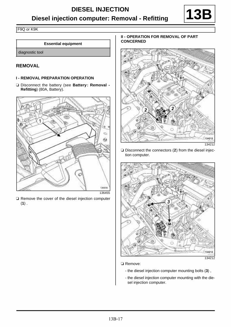
13B-17
DIESEL INJECTIONDiesel injection computer: Removal - Refitting
F9Q or K9K
13B
REMOVAL
I - REMOVAL PREPARATION OPERATION
a Disconnect the battery (see Battery : Removal -Refitting) (80A, Battery).
a Remove the cover of the diesel injection computer(1) .
II - OPERATION FOR REMOVAL OF PART CONCERNED
a Disconnect the connectors (2) from the diesel injec-tion computer.
a Remove:
- the diesel injection computer mounting bolts (3) ,
- the diesel injection computer mounting with the die-sel injection computer.
Essential equipment
diagnostic tool
136455
134212
134212

13B-18
DIESEL INJECTIONDiesel injection computer: Removal - Refitting
F9Q or K9K
13B
a Remove:
- the diesel injection computer nuts (4) ,
- the diesel injection computer from the diesel injec-tion computer mounting.
REFITTING
I - REFITTING OPERATION FOR PART CONCERNED
a Refit:
- the diesel injection computer on the diesel injectioncomputer mounting,
- the diesel injection computer nuts on the diesel in-jection computer mounting.
a Fit the diesel injection computer mounting with thediesel injection computer.
a Refit the diesel injection computer mounting bolts.
a Connect the diesel injection computer connectors.
II - FINAL OPERATION
a Refit the diesel injection computer cover.
a Connect the battery (see Battery : Removal - Refit-ting) (80A, Battery).
a Apply the after repair procedure using the diagnos-tic tool :
- connect the diagnostic tool,
- select the « Diesel injection computer » ,
- go to repair mode,
- display the « After repair procedure » for the selec-ted computer,
- carry out the operations described in the « After re-pair procedure » section.
134213

13B-19
DIESEL INJECTIONCamshaft position sensor: Removal - Refitting
K9K, and 832 or 834
13B
REMOVAL
I - REMOVAL PREPARATION OPERATION
a Remove the front engine cover.
a Separate the intercooler air outlet pipe clip (1) on thedamper valve.
a Disconnect the intercooler air outlet pipe from thedamper valve.
a Move the intercooler air outlet pipe slightly awayfrom the damper valve.
II - OPERATION FOR REMOVAL OF PART CONCERNED
a Disconnect the connector (2) from the camshaft po-sition sensor.
a Remove:
- the bolt (3) from the camshaft position sensor,
- the camshaft position sensor,
- the camshaft position sensor seal.
Tightening torquesm
intercooler air outletpipe clip on the dampervalve
5.5 N.m
134043
121889
121888

13B-20
DIESEL INJECTIONCamshaft position sensor: Removal - Refitting
K9K, and 832 or 834
13BREFITTING
I - REFITTING PREPARATION OPERATION
a parts always to be replaced: camshaft sensorseal (11,11,04,02).
a Lubricate the camshaft position sensor seal withnew engine oil.
II - REFITTING OPERATION FOR PART CONCERNED
a Refit:
- the camshaft position sensor fitted with a new seal,
- the camshaft position sensor bolt.
a Connect the camshaft position sensor connector.
III - FINAL OPERATION
a Fit the intercooler air outlet pipe.
a Connect the intercooler air outlet pipe on the dampervalve.
a Torque tighten the intercooler air outlet pipe clipon the damper valve (5.5 N.m).
a Refit the engine cover.

13B-21
DIESEL INJECTIONCamshaft position sensor: Removal - Refitting
K9K, and 830
13BREMOVAL
I - REMOVAL PREPARATION OPERATION
a Position the vehicle on a two-post lift (see Vehicle:Towing and lifting) (02A, Lifting equipment).
a Remove:
- the engine cover,
- the engine undertray bolts,
- the engine undertray,
- the lower engine tie-bar (see 19D, Engine moun-ting, Lower engine tie-bar: Removal - Refitting,page 19D-33) ,
- the windscreen wiper arms (see Windscreen wi-per arm: Removal - Refitting) (85A, Wiping -Washing),
- the scuttle panel grille (see Scuttle panel grille:Removal - Refitting) (56A, Exterior equipment),
- the scoop under the scuttle panel grille (see Scoopunder scuttle panel grille: Removal - Refitting)(56A, Exterior equipment),
- the right-hand suspended engine mounting (see19D, Engine mounting, Right-hand suspendedengine mounting: Removal - Refitting, page19D-18) .
II - OPERATION FOR REMOVAL OF PART CONCERNED
a Unclip the camshaft position sensor wiring from theupper timing cover (1)
a Disconnect the connector (2) from the camshaft po-sition sensor.
a Remove:
- the bolt (3) from the camshaft position sensor,
- the camshaft position sensor.
REFITTING
I - REFITTING PREPARATION OPERATION
a parts always to be replaced: camshaft sensorseal (11,11,04,02).
a Lubricate the camshaft position sensor seal.
II - REFITTING OPERATION FOR PART CONCERNED
a Refit the camshaft position sensor fitted with a newseal.
a Connect the camshaft position sensor connector.
a Clip the wiring of the camshaft position sensor ontothe upper timing cover.
136652
13B-22
DIESEL INJECTIONCamshaft position sensor: Removal - Refitting
K9K, and 830
13BIII - FINAL OPERATION
a Refit:
- the right-hand suspended engine mounting (see19D, Engine mounting, Right-hand suspendedengine mounting: Removal - Refitting, page19D-18) ,
- the scoop under the scuttle panel grille (see Scoopunder scuttle panel grille: Removal - Refitting)(56A, Exterior equipment),
- the scuttle panel grille (see Scuttle panel grille:Removal - Refitting) (56A, Exterior equipment),
- the windscreen wiper arms (see Windscreen wi-per arm: Removal - Refitting) (85A, Wiping -Washing),
- the lower engine tie-bar (see 19D, Engine moun-ting, Lower engine tie-bar: Removal - Refitting,page 19D-33) ,
- the engine undertray,
- the engine undertray bolts,
- the engine cover.

13B-23
DIESEL INJECTIONCamshaft position sensor: Removal - Refitting
F9Q
13B
REMOVAL
I - REMOVAL PREPARATION OPERATION
a Remove the front engine cover.
a Disconnect:
- the connector (1) from the EGR solenoid valve,
- the connector (2) from the turbocharger control so-lenoid valve,
- the connector (3) from the EGR bypass control so-lenoid valve.
a Remove the bolts (4) from the EGR bypass controlsolenoid valve.
a Move aside the EGR bypass control solenoid valve.
II - OPERATION FOR REMOVAL OF PART CONCERNED
a Disconnect the connector (5) from the camshaft po-sition sensor.
Tightening torquesm
EGR bypass controlsolenoid valve bolts
10 N.m
135988
135989
135990

13B-24
DIESEL INJECTIONCamshaft position sensor: Removal - Refitting
F9Q
13B
a Remove:
- the bolt (6) from the camshaft position sensor,
- the camshaft position sensor.
REFITTING
I - REFITTING OPERATION FOR PART CONCERNED
a Refit the camshaft position sensor.
a Connect the camshaft position sensor connector.
II - FINAL OPERATION
a Refit the EGR bypass control solenoid valve.
a Torque tighten the EGR bypass control solenoidvalve bolts (10 N.m).
a Connect:
- the EGR bypass control solenoid valve connector,
- the turbocharger control solenoid valve connector,
- the EGR solenoid valve connector.
a Refit the engine cover.
135991

13B-25
DIESEL INJECTIONCrankshaft position sensor: Removal - Refitting
K9K
13BREMOVAL
I - REMOVAL PREPARATION OPERATION
a Position the vehicle on a two-post lift (see Vehicle:Towing and lifting) (02A, Lifting equipment).
a Remove:
- the engine undertray bolts,
- the engine undertray.
II - OPERATION FOR REMOVAL OF PART CONCERNED
a Disconnect the crankshaft position sensor connector(1) .
a Remove:
- the crankshaft position sensor bolt (2) ,
- the crankshaft position sensor.
REFITTING
I - REFITTING OPERATION FOR PART CONCERNED
a Refit:
- the crankshaft position sensor,
- the crankshaft position sensor bolt.
a Connect the crankshaft position sensor connector.
II - FINAL OPERATION
a Refit the engine undertray.
123824

13B-26
DIESEL INJECTIONCrankshaft position sensor: Removal - Refitting
F9Q
13BREMOVAL
I - REMOVAL PREPARATION OPERATION
a Position the vehicle on a two-post lift (see Vehicle:Towing and lifting) (02A, Lifting equipment).
a Disconnect the battery (see Battery : Removal -Refitting) (80A, Battery).
a Remove:
- the engine undertray bolts,
- the engine undertray.
II - OPERATION FOR REMOVAL OF PART CONCERNED
a Disconnect the crankshaft position sensor connector(1) .
a Remove:
- the crankshaft position sensor bolt (2) ,
- the crankshaft position sensor.
REFITTING
I - REFITTING OPERATION FOR PART CONCERNED
a Refit the crankshaft position sensor.
a Connect the crankshaft position sensor connector.
II - FINAL OPERATION
a Refit the engine undertray.
a Connect the battery (see Battery : Removal - Refit-ting) (80A, Battery).
134180

13B-27
DIESEL INJECTIONLeak flow from high-pressure pump: Check
K9K, and 832
13B
CHECKING
I - PREPARATION OPERATION FOR CHECK
a Remove:
- the engine cover,
- the turbocharger air outlet pipe (see 12B, Turbo-charging, Intercooler air inlet pipe: Removal -Refitting, page 12B-41) .
a Separate the intercooler air outlet pipe clip (1) on thedamper valve.
a Disconnect the intercooler air outlet pipe from thedamper valve.
a Separate the intercooler air outlet pipe slightly fromthe damper valve.
a Disconnect:
- the connector (2) from the camshaft position sen-sor,
- the damper valve connector (3) .
a Unclip the camshaft position sensor wiring and thedamper valve wiring (4) from the injector rail protec-tor cover.
a Move aside the camshaft position sensor wiring anddamper valve wiring.
Essential special tooling
Mot. 1771 Kit for measuring SIEMENSinjector leak rate.
Essential equipment
graduated measuring cylinder
diagnostic tool
Tightening torquesm
intercooler air outletpipe clip on the dampervalve
5.5 N.m
intercooler air outletpipe clip on the dampervalve
5.5 N.m
134043
121889

13B-28
DIESEL INJECTIONLeak flow from high-pressure pump: Check
K9K, and 832
13B
a Unclip the injector rail protector cover at (5) .
a Remove:
- the injector rail protector cover bolt (6) ,
- the injector rail protector cover nut (7) ,
- the injection rail protector cover,
a Disconnect the diesel injector fuel return rail (8) fromthe high pressure pump.
a Fit a blanking plug onto the opening of the diesel in-jector fuel return rail.
a Connect the 8 mm diameter offset union fitted withits hose contained in the tool (Mot. 1771) to the highpressure pump union.
a Immerse this hose in the 500 ml graduated measu-ring cylinder.
a Connect:
- the camshaft position sensor connector,
- the damper valve connector,
- the intercooler outlet air pipe on the damper valve.
a Torque tighten the intercooler air outlet pipe clipon the damper valve (5.5 N.m).
a Refit the turbocharger air outlet pipe (see 12B, Tur-bocharging, Intercooler air inlet pipe: Removal -Refitting, page 12B-41) .
II - CHECKING OPERATION FOR PART CONCERNED
a Force the vehicle's + after ignition feed.
a Connect the diagnostic tool.
a Run commands:
- RZ009 "Program vehicle functions",
- VP036 "Inhibit fuel supply".
a Run the starter for 15 seconds.
a Check that the minimum flow is 25 ml for 15 se-conds.
a Run command VP037 "Stop fuel supply inhibition".
a Disconnect the diagnostic tool.
III - FINAL OPERATION
a Remove the turbocharger outlet air pipe (see 12B,Turbocharging, Intercooler air inlet pipe: Remo-val - Refitting, page 12B-41) .
a Separate the intercooler air outlet pipe clip on thedamper valve.
a Disconnect:
- the intercooler air outlet pipe on the damper valve,
- the damper valve connector,
- the camshaft position sensor connector.
a Disconnect the 8 mm diameter offset union fittedwith its hose contained in the tool (Mot. 1771) on thehigh pressure pump union.
a Remove the blanking plug from the diesel injectorfuel return rail opening.
134699
135009
WARNING
To prevent impurities from entering the circuit,place protective plugs on all fuel circuit compo-nents exposed to the open air.
13B-29
DIESEL INJECTIONLeak flow from high-pressure pump: Check
K9K, and 832
13Ba Connect the diesel injector fuel return rail to the high
pressure pump.
a Refit:
- the injector rail protector cover,
- the injector rail protector cover nut,
- the injector rail protector cover bolt.
a Clip on the injector rail protector cover.
a Fit the damper valve wiring.
a Clip the damper valve wiring onto the injector railprotector cover.
a Connect:
- the camshaft position sensor connector,
- the damper valve connector,
- the intercooler outlet air pipe on the damper valve.
a Torque tighten the intercooler air outlet pipe clipon the damper valve (5.5 N.m).
a Refit:
- the turbocharger air outlet pipe (see 12B, Turbo-charging, Intercooler air inlet pipe: Removal -Refitting, page 12B-41) ,
- the engine cover.

13B-30
DIESEL INJECTIONHigh pressure pump: Removal - Refitting
K9K, and 832
13B
REMOVAL
I - REMOVAL PREPARATION OPERATION
a Position the vehicle on a two-post lift (see Vehicle:Towing and lifting) (02A, Lifting equipment).
a Disconnect the battery (see Battery : Removal -Refitting) (80A, Battery).
a Remove:
- the engine cover,
- the front right-hand wheel (see Wheel: Removal -Refitting) (35A, Wheels and tyres),
- the front section of the front right-hand wheel archliner (see Front wheel arch liner: Removal - Re-fitting) (55A, Exterior protection),
- the engine undertray bolts,
- the engine undertray,
- the accessories belt (see 11A, Top and front ofengine, Accessories belt: Removal - Refitting,page 11A-7) ,
- the crankshaft accessories pulley (see 11A, Topand front of engine, Crankshaft accessoriespulley: Removal - Refitting, page 11A-15) ,
- the windscreen wiper arms (see Windscreen wi-per arm: Removal - Refitting) (85A, Wiping -Washing),
- the scuttle panel grille (see Scuttle panel grille:Removal - Refitting) (56A, Exterior equipment),
- the scoop under the scuttle panel grille (see Scoopunder scuttle panel grille: Removal - Refitting)(56A, Exterior equipment),
- the right-hand suspended engine mounting (see19D, Engine mounting, Right-hand suspendedengine mounting: Removal - Refitting, page19D-18) ,
- the timing belt (see 11A, Top and front of engine,Timing belt: Removal - Refitting, page 11A-29) .
a Remove the alternator upper bolt (1) .
a Loosen the alternator lower bolt (2) .
a Tilt the alternator slightly towards the front of the ve-hicle.
a Remove:
- the inner cover bolts (3) ,
- the inner cover,
Essential special tooling
Mot. 1768 Injection pump-pulley extrac-tor claws.
Mot. 1525 Extractor for timing gear withtapered hub.
Essential equipment
offset spanner
diagnostic tool
Tightening torquesm
high pressure pump pul-ley nut
70 N.m
high pressure pumpbolts
23 N.m
alternator lower bolt 25 N.m
alternator upper bolt 25 N.m
IMPORTANT
To avoid all risk of damage to the systems, applythe safety and cleanliness instructions and opera-tion recommendations before carrying out anyrepair (see 13B, Diesel injection, Diesel injec-tion: Precautions for repair, page 13B-1) .
123969

13B-31
DIESEL INJECTIONHigh pressure pump: Removal - Refitting
K9K, and 832
13B- the turbocharger air outlet pipe (see 12B, Turbo-charging, Intercooler air inlet pipe: Removal -Refitting, page 12B-41) ,
- the high pressure pipe between the high pressurepump and the injector rail (see 13B, Diesel injec-tion, High-pressure pipe between the pump andrail: Removal - Refitting, page 13B-71) .
a Disconnect the fuel supply pipe from the high pres-sure pump (4) .
a Fit a suitable blanking plug on the opening of:
- the fuel supply pipe,
- the high pressure pump.
a Remove:
- the high pressure pump protector nut (5) ,
- the high pressure pump protector bolt (6) ,
- the high pressure pump protector.
a Disconnect the diesel injector fuel return rail union(7) from the high pressure pump.
134707
135000
WARNING
To avoid any corrosion or damage, protect theareas on which fuel is likely to run.
135001
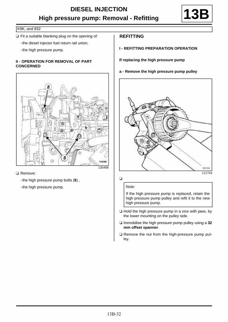
13B-32
DIESEL INJECTIONHigh pressure pump: Removal - Refitting
K9K, and 832
13Ba Fit a suitable blanking plug on the opening of:
- the diesel injector fuel return rail union,
- the high pressure pump.
II - OPERATION FOR REMOVAL OF PART CONCERNED
a Remove:
- the high pressure pump bolts (8) ,
- the high pressure pump.
REFITTING
I - REFITTING PREPARATION OPERATION
If replacing the high pressure pump
a - Remove the high pressure pump pulley
a
a Hold the high pressure pump in a vice with jaws, bythe lower mounting on the pulley side.
a Immobilise the high pressure pump pulley using a 32mm offset spanner.
a Remove the nut from the high-pressure pump pul-ley.
135498
111743
Note:
If the high pressure pump is replaced, retain thehigh pressure pump pulley and refit it to the newhigh pressure pump.

13B-33
DIESEL INJECTIONHigh pressure pump: Removal - Refitting
K9K, and 832
13B
a Fit tool (Mot. 1768) (9) on the tool (Mot. 1525) (10) .
a Remove the end piece (11) from the tool (Mot. 1525)(10) .
a Fit the (Mot. 1525) equipped with the (Mot. 1768) toextract the high pressure pump pulley.
a Protect the contact zones between the (Mot. 1525)and (Mot. 1768) and the high pressure pump pulley.
a Extract the high pressure pump pulley.
a A damaged high pressure pump pulley must alwaysbe replaced.
b - Refitting the high pressure pump pulley
a Place the new high pressure pump in a vice withjaws, securing it at the lower mounting on the highpressure pump pulley side.
a Refit the high pressure pump pulley.
a Immobilise the high pressure pump pulley using a 32mm offset spanner.
a Torque tighten the high pressure pump pulley nut(70 N.m).
II - REFITTING OPERATION FOR PART CONCERNED
a Refit the high pressure pump.
a Torque tighten the high pressure pump bolts (23N.m).
III - FINAL OPERATION
a Remove the blanking plugs from the opening of:
- the high pressure pump,
- the diesel injector fuel return rail union.
a Connect the diesel injector fuel return rail union onthe high pressure pump.
a Refit the high pressure pump protector.
a Remove the blanking plugs from:
- the fuel supply pipe,
- the high pressure pump.
a Connect the fuel supply pipe to the high pressurepump.
a Refit:
- the high pressure pipe between the high pressurepump and the injector rail (see 13B, Diesel injec-tion, High-pressure pipe between the pump andrail: Removal - Refitting, page 13B-71) ,
- the turbocharger air outlet pipe (see 12B, Turbo-charging, Intercooler air inlet pipe: Removal -Refitting, page 12B-41) ,
- the inner cover.
a Fit the alternator in place.
a Refit the alternator upper bolt.
a Tighten to torque:
- the alternator lower bolt (25 N.m),
- the alternator upper bolt (25 N.m).
a Refit:
- the timing belt (see 11A, Top and front of engine,Timing belt: Removal - Refitting, page 11A-29) ,
- the crankshaft accessories pulley (see 11A, Topand front of engine, Crankshaft accessoriespulley: Removal - Refitting, page 11A-15) ,
- the right-hand suspended engine mounting (see19D, Engine mounting, Right-hand suspendedengine mounting: Removal - Refitting, page19D-18) ,
- the scoop under the scuttle panel grille (see Scoopunder scuttle panel grille: Removal - Refitting)(56A, Exterior equipment),
135002
Note:
Be sure not to mark the high pressure pump pul-ley when extracting it using the (Mot. 1525)equipped with the (Mot. 1768).

13B-34
DIESEL INJECTIONHigh pressure pump: Removal - Refitting
K9K, and 832
13B- the scuttle panel grille (see Scuttle panel grille:Removal - Refitting) (56A, Exterior equipment),
- the windscreen wiper arms (see Windscreen wi-per arm: Removal - Refitting) (85A, Wiping -Washing),
- the engine undertray,
- the accessories belt (see 11A, Top and front ofengine, Accessories belt: Removal - Refitting,page 11A-7) ,
- the front section of the front right-hand wheel archliner (see Front wheel arch liner: Removal - Re-fitting) (55A, Exterior protection),
- the front right-hand wheel (see Wheel: Removal -Refitting) (35A, Wheels and tyres).
a Connect the battery (see Battery : Removal - Refit-ting) (80A, Battery).
a Refit the engine cover.
a Reprime the fuel circuit using the manual primingpump.
a Check that there are no diesel leaks.
a Apply the after repair procedure using the diagnos-tic tool :
- connect the diagnostic tool,
- select "Injection computer",
- go to repair mode,
- display the "After repair procedure" for the selectedcomputer,
- select "High pressure pump" in the "List of compo-nents stored by this computer" section,
- carry out the operations described in the "After re-pair procedure" section.

13B-35
DIESEL INJECTIONHigh pressure pump: Removal - Refitting
K9K, and 830
13B
REMOVAL
I - REMOVAL PREPARATION OPERATION
a Position the vehicle on a two-post lift (see Vehicle:Towing and lifting) (02A, Lifting equipment).
a Disconnect the battery (see Battery : Removal -Refitting) (80A, Battery).
a Remove:
- the engine cover,
- the front right-hand wheel (see Wheel: Removal -Refitting) (35A, Wheels and tyres),
- the front section of the front right-hand wheel archliner (see Front wheel arch liner: Removal - Re-fitting) (55A, Exterior protection),
- the engine undertray bolts,
- the engine undertray,
- the accessories belt (see 11A, Top and front ofengine, Accessories belt: Removal - Refitting,page 11A-7) ,
- the crankshaft accessories pulley (see 11A, Topand front of engine, Crankshaft accessoriespulley: Removal - Refitting, page 11A-15) ,
- the lower engine tie-bar (see 19D, Engine moun-ting, Lower engine tie-bar: Removal - Refitting,page 19D-33) ,
- the windscreen wiper arms (see Windscreen wi-per arm: Removal - Refitting) (85A, Wiping -Washing),
- the scuttle panel grille (see Scuttle panel grille:Removal - Refitting) (56A, Exterior equipment),
- the scoop under the scuttle panel grille (see Scoopunder scuttle panel grille: Removal - Refitting)(56A, Exterior equipment),
- the right-hand suspended engine mounting (see19D, Engine mounting, Right-hand suspendedengine mounting: Removal - Refitting, page19D-18) ,
- the camshaft position sensor (see 13B, Diesel in-jection, Camshaft position sensor: Removal -Refitting, page 13B-19) .
- the turbocharger air outlet pipe (see 12B, Turbo-charging, Intercooler air inlet pipe: Removal -Refitting, page 12B-41) .
- the high pressure pipe between the high pressurepump and the injector rail (see 13B, Diesel injec-tion, High-pressure pipe between the pump andrail: Removal - Refitting, page 13B-71) .
Essential special tooling
Mot. 1430 Set of 5 crankshaft and cams-haft pulley timing pins.
Mot. 1606 High pressure pump-pulleyretaining tool.
Mot. 1525 Extractor for timing gear withtapered hub.
Mot. 1525-02 Adapter sockets for Mot.1525.
Essential equipment
diagnostic tool
Tightening torquesm
the high pressure pumpbolts
23 N.m
high pressure pump pul-ley nut
70 N.m
right-hand suspendedengine mounting sup-port bolts
25 N.m
IMPORTANT
Wear leaktight gloves (Nitrile type) for this opera-tion.
IMPORTANT
To avoid all risk of damage to the systems, applythe safety and cleanliness instructions and opera-tion recommendations before carrying out anyrepair (see 13B, Diesel injection, Diesel injec-tion: Precautions for repair, page 13B-1) .

13B-36
DIESEL INJECTIONHigh pressure pump: Removal - Refitting
K9K, and 830
13B
a Unclip the upper timing cover at (1) .
a Remove:
- the bolt (2) from the upper timing cover,
- the upper timing cover.
a Remove:
- the right-hand suspended engine mounting supportbolts (3) ,
- the right-hand pendulum suspension support.
a Remove:
- the bolt (4) from the high pressure pump protector,
- the high pressure pump protector.
a Clean the fuel supply unions on the high pressurepump (see 13B, Diesel injection, Diesel injection:Precautions for repair, page 13B-1) .
136654
136656
136658
135873
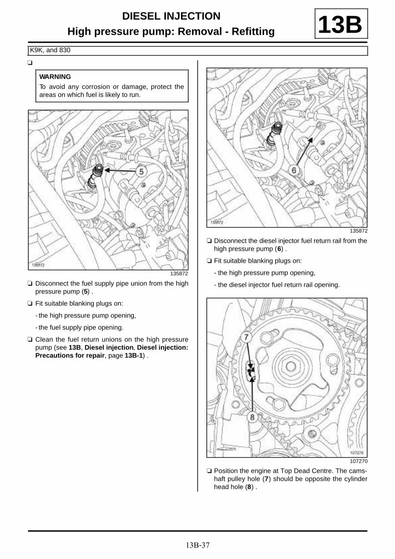
13B-37
DIESEL INJECTIONHigh pressure pump: Removal - Refitting
K9K, and 830
13Ba
a Disconnect the fuel supply pipe union from the highpressure pump (5) .
a Fit suitable blanking plugs on:
- the high pressure pump opening,
- the fuel supply pipe opening.
a Clean the fuel return unions on the high pressurepump (see 13B, Diesel injection, Diesel injection:Precautions for repair, page 13B-1) .
a Disconnect the diesel injector fuel return rail from thehigh pressure pump (6) .
a Fit suitable blanking plugs on:
- the high pressure pump opening,
- the diesel injector fuel return rail opening.
a Position the engine at Top Dead Centre. The cams-haft pulley hole (7) should be opposite the cylinderhead hole (8) .
WARNING
To avoid any corrosion or damage, protect theareas on which fuel is likely to run.
135872
135872
107270
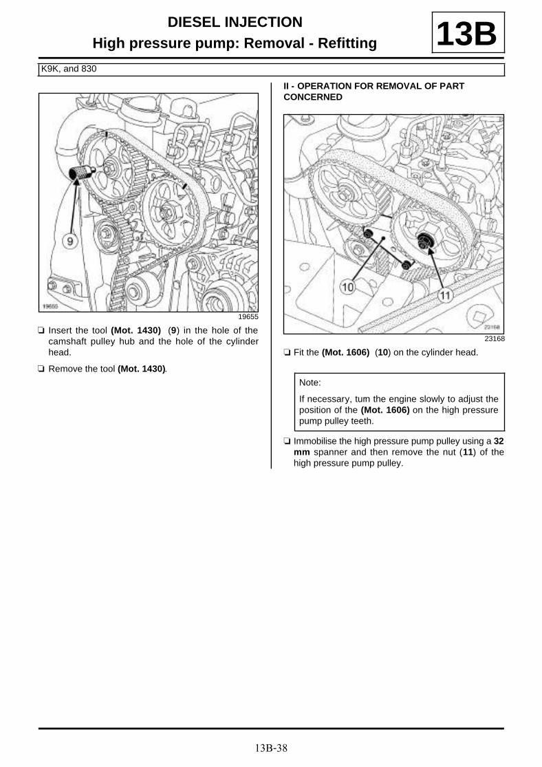
13B-38
DIESEL INJECTIONHigh pressure pump: Removal - Refitting
K9K, and 830
13B
a Insert the tool (Mot. 1430) (9) in the hole of thecamshaft pulley hub and the hole of the cylinderhead.
a Remove the tool (Mot. 1430).
II - OPERATION FOR REMOVAL OF PART CONCERNED
a Fit the (Mot. 1606) (10) on the cylinder head.
a Immobilise the high pressure pump pulley using a 32mm spanner and then remove the nut (11) of thehigh pressure pump pulley.
19655
23168
Note:
If necessary, turn the engine slowly to adjust theposition of the (Mot. 1606) on the high pressurepump pulley teeth.
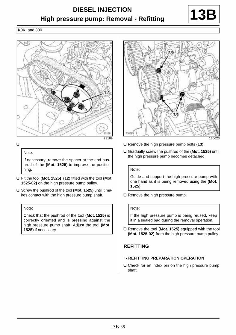
13B-39
DIESEL INJECTIONHigh pressure pump: Removal - Refitting
K9K, and 830
13B
a
a Fit the tool (Mot. 1525) (12) fitted with the tool (Mot.1525-02) on the high pressure pump pulley.
a Screw the pushrod of the tool (Mot. 1525) until it ma-kes contact with the high pressure pump shaft.
a Remove the high pressure pump bolts (13) .
a Gradually screw the pushrod of the (Mot. 1525) untilthe high pressure pump becomes detached.
a Remove the high pressure pump.
a Remove the tool (Mot. 1525) equipped with the tool(Mot. 1525-02) from the high pressure pump pulley.
REFITTING
I - REFITTING PREPARATION OPERATION
a Check for an index pin on the high pressure pumpshaft.
23169
Note:
If necessary, remove the spacer at the end pus-hrod of the (Mot. 1525) to improve the positio-ning.
Note:
Check that the pushrod of the tool (Mot. 1525) iscorrectly oriented and is pressing against thehigh pressure pump shaft. Adjust the tool (Mot.1525) if necessary.
136623
Note:
Guide and support the high pressure pump withone hand as it is being removed using the (Mot.1525)
Note:
If the high pressure pump is being reused, keepit in a sealed bag during the removal operation.
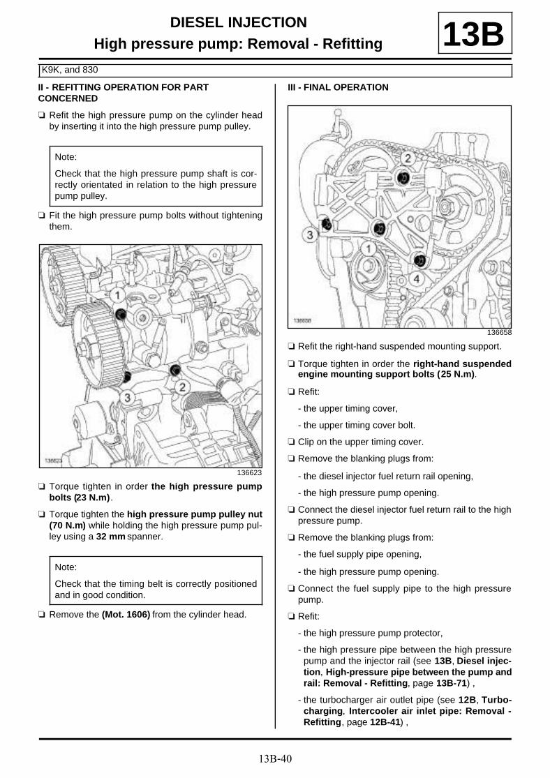
13B-40
DIESEL INJECTIONHigh pressure pump: Removal - Refitting
K9K, and 830
13BII - REFITTING OPERATION FOR PART CONCERNED
a Refit the high pressure pump on the cylinder headby inserting it into the high pressure pump pulley.
a Fit the high pressure pump bolts without tighteningthem.
a Torque tighten in order the high pressure pumpbolts (23 N.m).
a Torque tighten the high pressure pump pulley nut(70 N.m) while holding the high pressure pump pul-ley using a 32 mm spanner.
a Remove the (Mot. 1606) from the cylinder head.
III - FINAL OPERATION
a Refit the right-hand suspended mounting support.
a Torque tighten in order the right-hand suspendedengine mounting support bolts (25 N.m).
a Refit:
- the upper timing cover,
- the upper timing cover bolt.
a Clip on the upper timing cover.
a Remove the blanking plugs from:
- the diesel injector fuel return rail opening,
- the high pressure pump opening.
a Connect the diesel injector fuel return rail to the highpressure pump.
a Remove the blanking plugs from:
- the fuel supply pipe opening,
- the high pressure pump opening.
a Connect the fuel supply pipe to the high pressurepump.
a Refit:
- the high pressure pump protector,
- the high pressure pipe between the high pressurepump and the injector rail (see 13B, Diesel injec-tion, High-pressure pipe between the pump andrail: Removal - Refitting, page 13B-71) ,
- the turbocharger air outlet pipe (see 12B, Turbo-charging, Intercooler air inlet pipe: Removal -Refitting, page 12B-41) ,
Note:
Check that the high pressure pump shaft is cor-rectly orientated in relation to the high pressurepump pulley.
136623
Note:
Check that the timing belt is correctly positionedand in good condition.
136658

13B-41
DIESEL INJECTIONHigh pressure pump: Removal - Refitting
K9K, and 830
13B- the camshaft position sensor (see 13B, Diesel in-jection, Camshaft position sensor: Removal -Refitting, page 13B-19) ,
- the right-hand suspended engine mounting (see19D, Engine mounting, Right-hand suspendedengine mounting: Removal - Refitting, page19D-18) ,
- the scoop under the scuttle panel grille (see Scoopunder scuttle panel grille: Removal - Refitting)(56A, Exterior equipment),
- the scuttle panel grille (see Scuttle panel grille:Removal - Refitting) (56A, Exterior equipment),
- the windscreen wiper arms (see Windscreen wi-per arm: Removal - Refitting) (85A, Wiping -Washing),
- the lower engine tie-bar (see 19D, Engine moun-ting, Lower engine tie-bar: Removal - Refitting,page 19D-33) ,
- the crankshaft accessories pulley (see 11A, Topand front of engine, Crankshaft accessoriespulley: Removal - Refitting, page 11A-15) ,
- the accessories belt (see 11A, Top and front ofengine, Accessories belt: Removal - Refitting,page 11A-7) ,
- the engine undertray,
- the front section of the front right-hand wheel archliner (see Front wheel arch liner: Removal - Re-fitting) (55A, Exterior protection),
- the front right-hand wheel (see Wheel: Removal -Refitting) (35A, Wheels and tyres).
a Connect the battery (see Battery : Removal - Refit-ting) (80A, Battery).
a Reprime the fuel circuit using the manual primingpump.
a Check that there are no diesel leaks.
a Apply the after repair procedure using the diagnos-tic tool :
- connect the diagnostic tool,
- select the "Injection computer",
- go to repair mode,
- display the "After repair procedure" for the selectedcomputer,
- select "High pressure pump" in the "List of compo-nents stored by this computer",
- carry out the operations described in the "After re-pair procedure" section.

13B-42
DIESEL INJECTIONHigh pressure pump: Removal - Refitting
K9K, and 834
13B
REMOVAL
I - REMOVAL PREPARATION OPERATION
a Position the vehicle on a two-post lift (see Vehicle:Towing and lifting) (02A, Lifting equipment).
a Disconnect the battery (see Battery : Removal -Refitting) (80A, Battery).
a Remove:
- the engine cover,
- the front right-hand wheel (see Wheel: Removal -Refitting) (35A, Wheels and tyres),
- the front section of the front right-hand wheel archliner (see Front wheel arch liner: Removal - Re-fitting) (55A, Exterior protection),
- the engine undertray bolts,
- the engine undertray,
- the accessories belt (see 11A, Top and front ofengine, Accessories belt: Removal - Refitting,page 11A-7) ,
- the crankshaft accessories pulley (see 11A, Topand front of engine, Crankshaft accessoriespulley: Removal - Refitting, page 11A-15) ,
- the lower engine tie-bar (see 19D, Engine moun-ting, Lower engine tie-bar: Removal - Refitting,page 19D-33) ,
- the windscreen wiper arms (see Windscreen wi-per arm: Removal - Refitting) (85A, Wiping -Washing),
- the scuttle panel grille (see Scuttle panel grille:Removal - Refitting) (56A, Exterior equipment),
- the scoop under the scuttle panel grille (see Scoopunder scuttle panel grille: Removal - Refitting)(56A, Exterior equipment).
- the right-hand suspended engine mounting (see19D, Engine mounting, Right-hand suspendedengine mounting: Removal - Refitting, page19D-18) ,
- the timing belt (see 11A, Top and front of engine,Timing belt: Removal - Refitting, page 11A-29) ,
- the high pressure pipe between the high pressurepump and the injector rail (see 13B, Diesel injec-tion, High-pressure pipe between the rail andinjector: Removal - Refitting, page 13B-87) .
Essential special tooling
Mot. 1525 Extractor for timing gear withtapered hub.
Mot. 1525-02 Adapter sockets for Mot.1525.
Essential equipment
offset spanner
diagnostic tool
Tightening torquesm
high pressure pump pul-ley nut
70 N.m
fuel supply pipe unionprotection bracket bolt
23 N.m
high pressure pumpbolts
23 N.m
injector rail protectornuts
21 N.m
dipstick guide bolt 8 N.m
inner cover bolts 9 N.m
alternator bolts 25 N.m
IMPORTANT
Wear leaktight gloves (Nitrile type) for this opera-tion.
IMPORTANT
To avoid all risk of damage to the systems, applythe safety and cleanliness instructions and opera-tion recommendations before carrying out anyrepair (see 13B, Diesel injection, Diesel injec-tion: Precautions for repair, page 13B-1) .
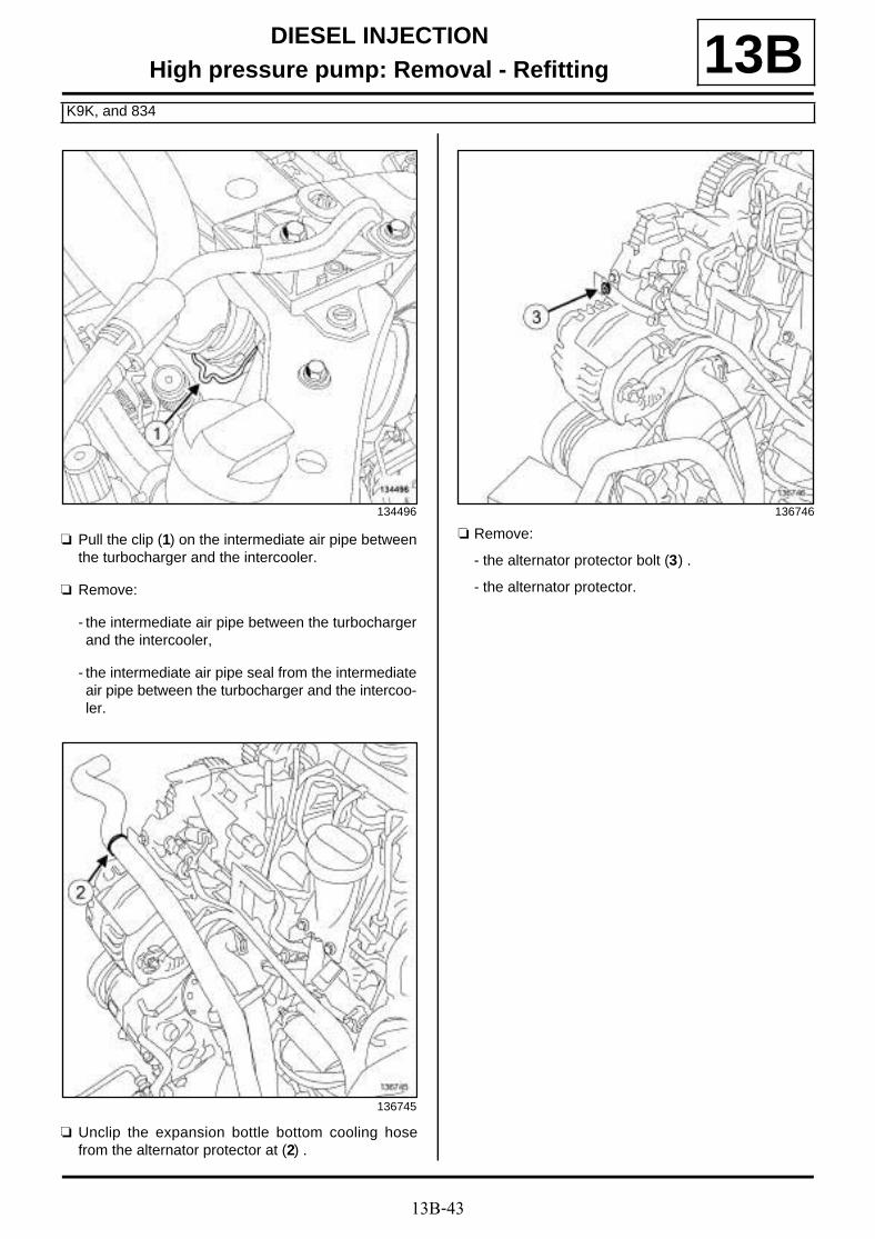
13B-43
DIESEL INJECTIONHigh pressure pump: Removal - Refitting
K9K, and 834
13B
a Pull the clip (1) on the intermediate air pipe betweenthe turbocharger and the intercooler.
a Remove:
- the intermediate air pipe between the turbochargerand the intercooler,
- the intermediate air pipe seal from the intermediateair pipe between the turbocharger and the intercoo-ler.
a Unclip the expansion bottle bottom cooling hosefrom the alternator protector at (2) .
a Remove:
- the alternator protector bolt (3) .
- the alternator protector.
134496
136745
136746

13B-44
DIESEL INJECTIONHigh pressure pump: Removal - Refitting
K9K, and 834
13B
a Disconnect the fuel supply pipe union (4) from thehigh pressure pump.
a Fit a suitable blanking plug on:
- the high pressure pump opening,
- the fuel supply pipe opening.
a Disconnect:
- the flow actuator connector (5) ,
- the fuel temperature sensor connector (6) .
a Unclip the alternator wiring from the injector rail pro-tector.
a Remove the alternator upper bolt (7) .
a Loosen the alternator lower bolt (8) .
a Tilt the alternator forward.
a Remove:
- the inner timing cover bolts (9) ,
- the inner timing cover.
136618 136742
136739

13B-45
DIESEL INJECTIONHigh pressure pump: Removal - Refitting
K9K, and 834
13B
a Remove:
- the dipstick,
- the dipstick guide bolts (10) .
a Move aside the dipstick guide.
a Disconnect the injector rail pressure sensor connec-tor (11) .
a Unclip the diesel drain pipe (12) from the injector railprotector.
a Disconnect:
- the fuel supply pipe union (13) of the exhaust fuelinjector from the fuel supply solenoid valve of theexhaust fuel injector,
- the fuel supply pipe union (14) of the exhaust fuelinjector from the high pressure pump.
a Remove the fuel supply pipe from the exhaust fuelinjector.
a Fit suitable blanking plugs on:
- the opening of the fuel supply solenoid valve for theexhaust fuel injector,
- the high pressure pump opening,
- the pipe openings of the exhaust fuel injector fuelsupply solenoid valve.
136616 136615
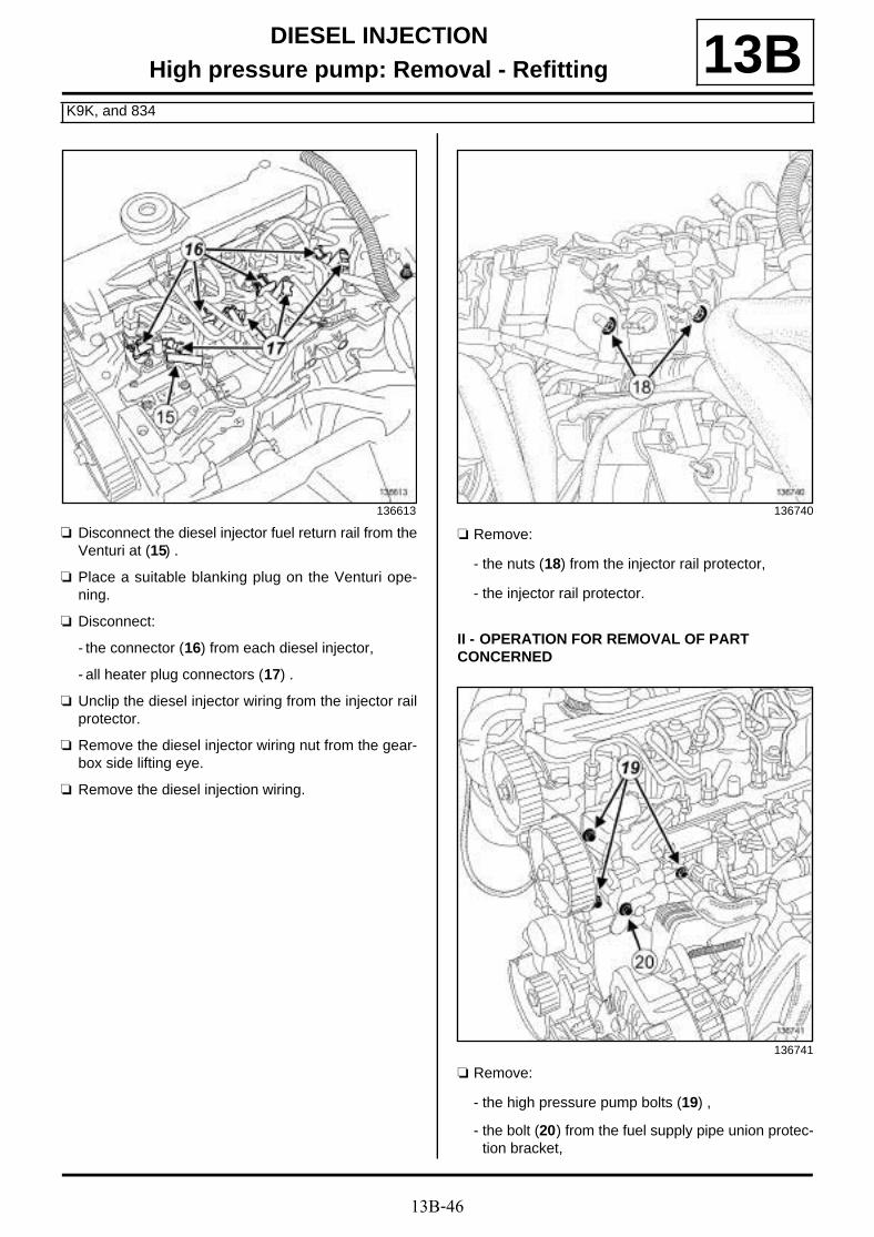
13B-46
DIESEL INJECTIONHigh pressure pump: Removal - Refitting
K9K, and 834
13B
a Disconnect the diesel injector fuel return rail from theVenturi at (15) .
a Place a suitable blanking plug on the Venturi ope-ning.
a Disconnect:
- the connector (16) from each diesel injector,
- all heater plug connectors (17) .
a Unclip the diesel injector wiring from the injector railprotector.
a Remove the diesel injector wiring nut from the gear-box side lifting eye.
a Remove the diesel injection wiring.
a Remove:
- the nuts (18) from the injector rail protector,
- the injector rail protector.
II - OPERATION FOR REMOVAL OF PART CONCERNED
a Remove:
- the high pressure pump bolts (19) ,
- the bolt (20) from the fuel supply pipe union protec-tion bracket,
136613 136740
136741

13B-47
DIESEL INJECTIONHigh pressure pump: Removal - Refitting
K9K, and 834
13B- the fuel supply pipe union protection bracket,
- the high pressure pump
REFITTING
I - REFITTING PREPARATION OPERATION
a Always replace the seal on the intermediate air pipebetween the turbocharger and the intercooler.
If replacing the high pressure pump
a
a
a Secure the high pressure pump in a vice with jaws,by the lower bolt hole on the high pressure pumppulley side.
a Immobilise the high pressure pump pulley using aoffset spanner.
a Remove the nut from the high-pressure pump pul-ley.
a Remove the end piece (21) of the tool (Mot. 1525)by unscrewing the bolt (22) .
a Protect the contact areas between the tool (Mot.1525) equipped with the tool (Mot. 1525-02) and thehigh pressure pump pulley.
a Fit the tool (Mot. 1525) equipped with the tool (Mot.1525-02) to remove the high pressure pump pulley.
a Remove the high pressure pump pulley.
a A damaged high pressure pump pulley must alwaysbe replaced.
a Remove the old high pressure pump from the vice.
a Place the new high pressure pump in a vice withjaws, by the lower bolt hole on the high pressurepump pulley side.
a Refit the high pressure pump pulley.
a Immobilise the high pressure pulley using a offsetspanner.
a Torque tighten the high pressure pump pulley nut(70 N.m).
Note:
If replacing a high pressure pump, only removethe new high pressure pump from its originalpackaging when it is about to be fitted.
136621
Note:
If the high pressure pump is replaced, retain thehigh pressure pump pulley and refit it to the newhigh pressure pump.
136619

13B-48
DIESEL INJECTIONHigh pressure pump: Removal - Refitting
K9K, and 834
13BII - REFITTING OPERATION FOR PART CONCERNED
a Refit:
- the high pressure pump,
- the fuel supply pipe union protection bracket.
a Tighten to torque:
- the fuel supply pipe union protection bracketbolt (23 N.m) (23) ,
- the high pressure pump bolts (23 N.m) (24) .
III - FINAL OPERATION
a Refit the injector rail protector.
a Torque tighten the injector rail protector nuts (21N.m).
a Fit the diesel injection wiring.
a Refit the diesel injection wiring nut on the gearboxside lifting eye.
a Clip the diesel injection wiring onto the injector railprotector.
a Connect:
- all heater plug connectors,
- the connector for each diesel injector.
a Remove the blanking plug from the opening of theVenturi.
a Connect the diesel injector fuel return rail to the Ven-turi.
a Remove the blanking plugs from:
- the opening of the fuel supply solenoid valve of theexhaust fuel injector,
- the opening of the high pressure pump,
- the pipe openings of the exhaust fuel injector fuelsupply solenoid valve.
a Refit the fuel supply pipe on the exhaust fuel injec-tor.
a Connect:
- the union of the exhaust fuel injector fuel supplypipe on the high pressure pump.
- the union of the exhaust fuel injector fuel supplypipe to the exhaust fuel injector fuel supply sole-noid valve.
a Clip the diesel drain pipe onto the injector rail protec-tor.
a Connect the injector rail pressure sensor connector.
a Fit the dipstick guide.
a Torque tighten the dipstick guide bolt (8 N.m).
a Refit:
- the dipstick,
- the inner timing cover.
a Torque tighten the inner cover bolts (9 N.m).
a Fit the alternator in place.
a Refit the alternator upper bolt.
a Torque tighten the alternator bolts (25 N.m).
a Clip the alternator wiring onto the injector rail protec-tor.
a Connect:
- the fuel temperature sensor connector,
- the flow actuator connector.
a Remove the blanking plugs from:
- the high pressure pump opening,
- the fuel supply pipe opening.
a Connect the fuel supply pipe union to the high pres-sure pump.
a Refit:
- the alternator protector,
- the alternator protector bolt.
a Clip the expansion bottle bottom cooling hose ontothe alternator protector.
136741
13B-49
DIESEL INJECTIONHigh pressure pump: Removal - Refitting
K9K, and 834
13Ba Refit:
- a new seal on the intermediate air pipe betweenthe turbocharger and the intercooler,
- the intermediate air pipe clip between the turbo-charger and the intercooler.
a Clip the intermediate air pipe between the turbochar-ger and the intercooler on the intercooler air inlet pi-pe.
a Refit:
- the high pressure pipe between the high pressurepump and the injector rail (see 13B, Diesel injec-tion, High-pressure pipe between the rail andinjector: Removal - Refitting, page 13B-87) ,
- the timing belt (see 11A, Top and front of engine,Timing belt: Removal - Refitting, page 11A-29) ,
- the right-hand suspended engine mounting (see19D, Engine mounting, Right-hand suspendedengine mounting: Removal - Refitting, page19D-18) ,
- the scoop under the scuttle panel grille (see Scoopunder scuttle panel grille: Removal - Refitting)(56A, Exterior equipment).
- the scuttle panel grille (see Scuttle panel grille:Removal - Refitting) (56A, Exterior equipment),
- the windscreen wiper arms (see Windscreen wi-per arm: Removal - Refitting) (85A, Wiping -Washing).
- the lower engine tie-bar (see 19D, Engine moun-ting, Lower engine tie-bar: Removal - Refitting,page 19D-33)
- the accessories belt (see 11A, Top and front ofengine, Accessories belt: Removal - Refitting,page 11A-7) ,
- the engine undertray,
- the front section of the front right-hand wheel archliner (see Front wheel arch liner: Removal - Re-fitting) (55A, Exterior protection),
- the front right-hand wheel (see Wheel: Removal -Refitting) (35A, Wheels and tyres),
- the engine cover.
a Connect the battery (see Battery : Removal - Refit-ting) (80A, Battery).
a Apply the after repair procedure using the diagnos-tic tool :
- connect the diagnostic tool,
- select "Injection computer",
- go to repair mode,
- display the "After repair procedure" for the selectedcomputer,
- select "High pressure pump" in the "List of compo-nents stored by this computer" section,
- carry out the operations described in the "After re-pair procedure" section.

13B-50
DIESEL INJECTIONHigh pressure pump: Removal - Refitting
F9Q
13B
REMOVAL
I - REMOVAL PREPARATION OPERATION
a Position the vehicle on a two-post lift (see Vehicle:Towing and lifting) (02A, Lifting equipment).
a Disconnect the battery (see Battery : Removal -Refitting) (80A, Battery).
a Remove:
- the engine cover,
- the engine undertray bolts,
- the engine undertray,
- the front right-hand wheel (see Wheel: Removal -Refitting) (35A, Wheels and tyres),
- the accessories belt (see 11A, Top and front ofengine, Accessories belt: Removal - Refitting,page 11A-7) ,
- the crankshaft accessories pulley (see 11A, Topand front of engine, Crankshaft accessoriespulley: Removal - Refitting, page 11A-15) ,
- the windscreen wiper arms (see Windscreen wi-per arm: Removal - Refitting) (85A, Wiping -Washing),
- the scuttle panel grille (see Scuttle panel grille:Removal - Refitting) (56A, Exterior equipment),
- the scoop under the scuttle panel grille (see Scoopunder scuttle panel grille: Removal - Refitting)(56A, Exterior equipment),
- the right-hand suspended engine mounting (see19D, Engine mounting, Right-hand suspendedengine mounting: Removal - Refitting, page19D-18) ,
- the timing belt (see 11A, Top and front of engine,Timing belt: Removal - Refitting, page 11A-29) ,
- the injector rail protector (see 13B, Diesel injec-tion, Injector rail protector: Removal - Refitting,page 13B-70) ,
- the fuel temperature sensor (see 13B, Diesel in-jection, Fuel temperature sensor: Removal -Refitting, page 13B-118) ,
- the high pressure pipe between the pump and therail (see 13B, Diesel injection, High-pressurepipe between the pump and rail: Removal - Re-fitting, page 13B-71) .
Essential special tooling
Mot. 1668 Locking high pressure pumpsprocket.
Mot. 1525 Extractor for timing gear withtapered hub.
Mot. 1525-03 Adapter sockets for Mot.1525.(for 33-tooth pulley).
Tightening torquesm
high pressure pumpbolts
25 N.m
high pressure pump pul-ley nut
50 N.m
high pressure pumpsupport bolts on thecylinder head
20 N.m + 80˚
bolt for the high pres-sure pump rear support
30 N.m
IMPORTANT
To avoid all risk of damage to the systems, applythe safety and cleanliness instructions and opera-tion recommendations before carrying out anyrepair (see 13B, Diesel injection, Diesel injec-tion: Precautions for repair, page 13B-1) .
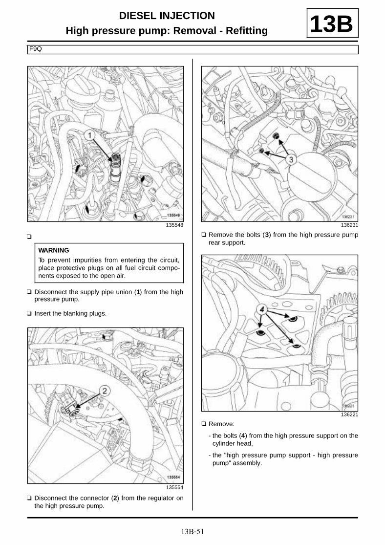
13B-51
DIESEL INJECTIONHigh pressure pump: Removal - Refitting
F9Q
13B
a
a Disconnect the supply pipe union (1) from the highpressure pump.
a Insert the blanking plugs.
a Disconnect the connector (2) from the regulator onthe high pressure pump.
a Remove the bolts (3) from the high pressure pumprear support.
a Remove:
- the bolts (4) from the high pressure support on thecylinder head,
- the "high pressure pump support - high pressurepump" assembly.
135548
WARNING
To prevent impurities from entering the circuit,place protective plugs on all fuel circuit compo-nents exposed to the open air.
135554
136231
136221
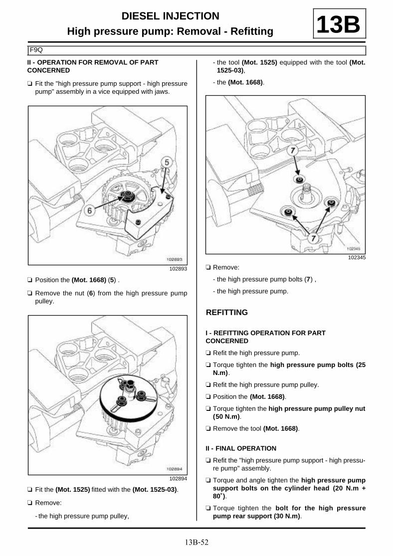
13B-52
DIESEL INJECTIONHigh pressure pump: Removal - Refitting
F9Q
13BII - OPERATION FOR REMOVAL OF PART CONCERNED
a Fit the "high pressure pump support - high pressurepump" assembly in a vice equipped with jaws.
a Position the (Mot. 1668) (5) .
a Remove the nut (6) from the high pressure pumppulley.
a Fit the (Mot. 1525) fitted with the (Mot. 1525-03).
a Remove:
- the high pressure pump pulley,
- the tool (Mot. 1525) equipped with the tool (Mot.1525-03),
- the (Mot. 1668).
a Remove:
- the high pressure pump bolts (7) ,
- the high pressure pump.
REFITTING
I - REFITTING OPERATION FOR PART CONCERNED
a Refit the high pressure pump.
a Torque tighten the high pressure pump bolts (25N.m).
a Refit the high pressure pump pulley.
a Position the (Mot. 1668).
a Torque tighten the high pressure pump pulley nut(50 N.m).
a Remove the tool (Mot. 1668).
II - FINAL OPERATION
a Refit the "high pressure pump support - high pressu-re pump" assembly.
a Torque and angle tighten the high pressure pumpsupport bolts on the cylinder head (20 N.m +80˚).
a Torque tighten the bolt for the high pressurepump rear support (30 N.m).
102893
102894
102345
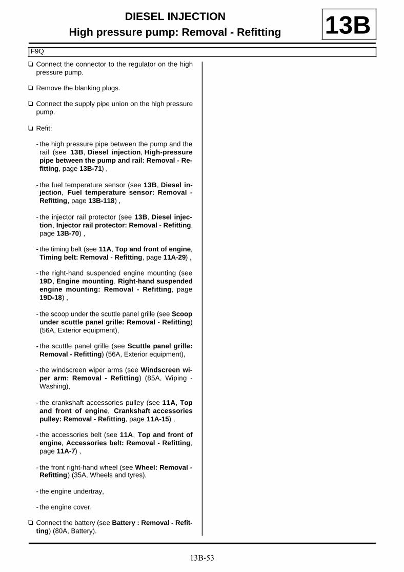
13B-53
DIESEL INJECTIONHigh pressure pump: Removal - Refitting
F9Q
13Ba Connect the connector to the regulator on the high
pressure pump.
a Remove the blanking plugs.
a Connect the supply pipe union on the high pressurepump.
a Refit:
- the high pressure pipe between the pump and therail (see 13B, Diesel injection, High-pressurepipe between the pump and rail: Removal - Re-fitting, page 13B-71) ,
- the fuel temperature sensor (see 13B, Diesel in-jection, Fuel temperature sensor: Removal -Refitting, page 13B-118) ,
- the injector rail protector (see 13B, Diesel injec-tion, Injector rail protector: Removal - Refitting,page 13B-70) ,
- the timing belt (see 11A, Top and front of engine,Timing belt: Removal - Refitting, page 11A-29) ,
- the right-hand suspended engine mounting (see19D, Engine mounting, Right-hand suspendedengine mounting: Removal - Refitting, page19D-18) ,
- the scoop under the scuttle panel grille (see Scoopunder scuttle panel grille: Removal - Refitting)(56A, Exterior equipment),
- the scuttle panel grille (see Scuttle panel grille:Removal - Refitting) (56A, Exterior equipment),
- the windscreen wiper arms (see Windscreen wi-per arm: Removal - Refitting) (85A, Wiping -Washing),
- the crankshaft accessories pulley (see 11A, Topand front of engine, Crankshaft accessoriespulley: Removal - Refitting, page 11A-15) ,
- the accessories belt (see 11A, Top and front ofengine, Accessories belt: Removal - Refitting,page 11A-7) ,
- the front right-hand wheel (see Wheel: Removal -Refitting) (35A, Wheels and tyres),
- the engine undertray,
- the engine cover.
a Connect the battery (see Battery : Removal - Refit-ting) (80A, Battery).

13B-54
DIESEL INJECTIONFuel flow actuator: Removal - Refitting
K9K, and 830
13B
REMOVAL
I - OPERATION FOR REMOVAL OF PART CONCERNED
a Remove the engine cover.
a Disconnect the battery (see Battery : Removal -Refitting) (80A, Battery).
a Remove the turbocharger outlet air pipe (see 12B,Turbocharging, Intercooler air inlet pipe: Remo-val - Refitting, page 12B-41) .
a Unclip the injector rail protector cover at (1) .
a Remove:
- the injector rail protector cover bolt (2) ,
- the injection rail protector cover,
II - OPERATION FOR REMOVAL OF PART CONCERNED
a Disconnect the flow actuator connector (3) .
a Remove:
- the flow actuator bolts (4) ,
- the fuel flow actuator
IMPORTANT
To avoid all risk of damage to the systems, applythe safety and cleanliness instructions and opera-tion recommendations before carrying out anyrepair (see 13B, Diesel injection, Diesel injec-tion: Precautions for repair, page 13B-1) .
Note:
Ensure that you have a new flow actuator beforeopening up the fuel circuit.
135878
135874
135865

13B-55
DIESEL INJECTIONFuel flow actuator: Removal - Refitting
K9K, and 830
13Ba Make sure that no impurities enter the high pressure
pump when the fuel flow actuator is removed.
REFITTING
I - REFITTING PREPARATION OPERATION
a parts always to be replaced: Fuel flow regulatorseal on injection pump (11,05,10,20).
II - REFITTING OPERATION FOR PART CONCERNED
a Refit the flow actuator to the high pressure pump.
a Connect the flow actuator connector.
III - FINAL OPERATION
a Prime the fuel circuit using the manual primingpump.
a Refit the injector rail protector cover.
a Clip on the injector rail protector cover.
a Refit the turbocharger air outlet pipe (see 12B, Tur-bocharging, Intercooler air inlet pipe: Removal -Refitting, page 12B-41) .
a Connect the battery (see Battery : Removal - Refit-ting) (80A, Battery).
a Start the engine.
a Check that there are no fuel leaks.
a Refit the engine cover.
WARNING
Do not blast with compressed air once the fuelcircuit is open, otherwise impurities may enterthe system. Only use cleaning cloths.
WARNING
Do not remove the blanking plugs from eachcomponent until the last moment.
Also, do not remove the components from theirpackaging until they are to be fitted to the vehi-cle.

13B-56
DIESEL INJECTIONFuel flow actuator: Removal - Refitting
K9K, and 834
13B
REMOVAL
I - REMOVAL PREPARATION OPERATION
a Disconnect the battery (see Battery : Removal -Refitting) (80A, Battery).
a Remove the front engine cover.
II - OPERATION FOR REMOVAL OF PART CONCERNED
a Disconnect:
- the fuel temperature sensor connector (1) ,
- the flow actuator connector (2) .
IMPORTANT
To avoid all risk of damage to the systems, applythe safety and cleanliness instructions and opera-tion recommendations before carrying out anyrepair (see 13B, Diesel injection, Diesel injec-tion: Precautions for repair, page 13B-1) .
IMPORTANT
Wear leaktight gloves (Nitrile type) for this opera-tion.
137858
WARNING
Prepare for the flow of fluid, and protect the sur-rounding components.
WARNING
Do not blast with compressed air once the fuelcircuit is open, otherwise impurities may enterthe system. Only use cleaning cloths.
Note:
Make sure that no impurities enter the high pres-sure pump when the fuel flow actuator is remo-ved.

13B-57
DIESEL INJECTIONFuel flow actuator: Removal - Refitting
K9K, and 834
13B
a Remove:
- the flow actuator bolts (3) ,
- the flow actuator from the high pressure pump (byhand with small tugs and successive turns).
REFITTING
I - REFITTING PREPARATION OPERATION
a
II - REFITTING OPERATION FOR PART CONCERNED
a Refit:
- the flow actuator on the high pressure pump,
- the flow actuator bolts.
III - FINAL OPERATION
a Refit the engine cover.
a Connect the battery (see Battery : Removal - Refit-ting) (80A, Battery).
137860
Note:
Do not lubricate the seals with grease or old die-sel fuel. Use the applicator provided in the kit forthe new part.

13B-58
DIESEL INJECTIONVenturi: Removal - Refitting
K9K, and 830
13B
REMOVAL
I - REMOVAL PREPARATION OPERATION
a Remove:
- the engine cover,
- the turbocharger air outlet pipe (see 12B, Turbo-charging, Intercooler air inlet pipe: Removal -Refitting, page 12B-41) .
II - OPERATION FOR REMOVAL OF PART CONCERNED
a Disconnect the diesel fuel return pipe union from theVenturi (1) .
a Fit blanking plugs on:
- the opening of the venturi,
- the diesel fuel return pipe opening.
a Disconnect the diesel fuel injector return rail from theVenturi (2) .
a Fit suitable blanking plugs on:
- the opening of the venturi,
- the opening of the diesel injector fuel return rail.
Tightening torquesm
Venturi bolt 5.5 N.m
IMPORTANT
To avoid all risk of damage to the systems, applythe safety and cleanliness instructions and opera-tion recommendations before carrying out anyrepair (see 13B, Diesel injection, Diesel injec-tion: Precautions for repair, page 13B-1) .
WARNINGTo avoid any corrosion or damage, protect theareas on which fuel is likely to run.
WARNING
Keep the pipe unions away from contaminatedareas.
Note:
Ensure that you have a new Venturi before openingup the fuel circuit.
135867

13B-59
DIESEL INJECTIONVenturi: Removal - Refitting
K9K, and 830
13B
a Remove:
- the Venturi bolt (3) ,
- the Venturi.
a Take care to ensure that no impurities get into thehigh pressure pump once the Venturi is removed.
REFITTING
I - REFITTING OPERATION FOR PART CONCERNED
a
a Refit the venturi to the high pressure pump.
a Torque tighten the Venturi bolt (5.5 N.m).
a Remove the blanking plugs from:
- the diesel injector fuel return rail opening,
- the Venturi opening.
a Connect the fuel return rail to the Venturi.
a Remove the blanking plugs from:
- the opening of the diesel fuel return pipe union,
- the Venturi opening.
a Connect the diesel return pipe to the Venturi.
II - FINAL OPERATION
a Refit the turbocharger air outlet pipe (see 12B, Tur-bocharging, Intercooler air inlet pipe: Removal -Refitting, page 12B-41) .
a Start the engine.
a Check that there are no fuel leaks.
a Refit the engine cover.
135866
WARNING
Do not blast with compressed air once the fuelcircuit is open, otherwise impurities may enterthe system. Only use cleaning cloths.
Note:
Do not lubricate the seals with grease or useddiesel fuel. Use the applicator provided in the kitfor the new part.

13B-60
DIESEL INJECTIONVenturi: Removal - Refitting
K9K, and 834
13B
REMOVAL
I - REMOVAL PREPARATION OPERATION
a Remove the front engine cover.
a Disconnect from the Venturi:
- the diesel fuel return pipe union (1) ,
- the diesel injector fuel return rail (2) .
a Fit blanking plugs on:
- the openings of the Venturi,
- the diesel return pipe opening.
Tightening torquesm
Venturi bolt 5.5 N.m
IMPORTANT
To avoid all risk of damage to the systems, applythe safety and cleanliness instructions and opera-tion recommendations before carrying out anyrepair (see 13B, Diesel injection, Diesel injec-tion: Precautions for repair, page 13B-1) .
IMPORTANTWear leaktight gloves (Nitrile type) for this opera-tion.
Note:
Make sure that you have a new venturi before ope-ning the fuel circuit.
WARNING
Prepare for the flow of fluid, and protect the sur-rounding components.
137855

13B-61
DIESEL INJECTIONVenturi: Removal - Refitting
K9K, and 834
13BII - OPERATION FOR REMOVAL OF PART CONCERNED
a Remove:
- the Venturi bolt (3) ,
- the Venturi from the high pressure pump (withsmall tugs and successive turns).
REFITTING
I - REFITTING PREPARATION OPERATION
a
II - REFITTING OPERATION FOR PART CONCERNED
a Refit the venturi to the high pressure pump.
a Torque tighten the Venturi bolt (5.5 N.m).
III - FINAL OPERATION
a Remove the blanking plugs from:
- the openings of the Venturi,
- the diesel fuel return pipe opening.
a Connect:
- the diesel injector fuel return rail to the Venturi,
- the diesel fuel return pipe union to the Venturi.
a Refit the engine cover.
137856
Note:
Do not lubricate the seals with grease or old die-sel fuel. Use the applicator provided in the kit forthe new part.
13B-62
DIESEL INJECTIONDiesel return pipe: Removal - Refitting
F9Q
13Ba The diesel return pipe is not sold separately by the
Parts Department; to replace it, it is necessary to re-place the fuel temperature sensor (see 13B, Dieselinjection, Fuel temperature sensor: Removal -Refitting, page 13B-118) .

13B-63
DIESEL INJECTIONDiesel injector fuel return rail: Removal - Refitting
F9Q
13B
REMOVAL
I - REMOVAL PREPARATION OPERATION
a Disconnect the battery (see Battery : Removal -Refitting) (80A, Battery).
a Remove:
- the engine cover,
- the injector rail protector (see 13B, Diesel injec-tion, Injector rail protector: Removal - Refitting,page 13B-70) .
II - OPERATION FOR REMOVAL OF PART CONCERNED
a
a Disconnect the union (1) between the diesel tempe-rature sensor and the diesel fuel injector return rail.
a Place blanking plugs:
- on the diesel injector fuel return rail,
- on the diesel temperature sensor.
IMPORTANT
To avoid all risk of damage to the systems, applythe safety and cleanliness instructions and opera-tion recommendations before carrying out anyrepair (see 13B, Diesel injection, Diesel injec-tion: Precautions for repair, page 13B-1) .
136196
WARNING
To prevent impurities from entering the circuit,place protective plugs on all fuel circuit compo-nents exposed to the open air.

13B-64
DIESEL INJECTIONDiesel injector fuel return rail: Removal - Refitting
F9Q
13B
a Press the injector clips.
a Vertically pull the end piece of the fuel return rail oneach diesel fuel injector.
a Remove the diesel injector fuel return rail.
a Fit blanking plugs onto the injectors.
a Place the diesel injector fuel return rail in a protecti-ve bag.
REFITTING
I - REFITTING PREPARATION OPERATION
a
II - REFITTING OPERATION FOR PART CONCERNED
a Take the diesel injector fuel return rail out of the pro-tective bag or out of its packaging.
a Remove the blanking plugs.
a Refit the diesel injector fuel return rail.
a Connect the union between the diesel temperaturesensor and the diesel fuel injector return rail.
III - FINAL OPERATION
a Refit:
- the injector rail protector (see 13B, Diesel injec-tion, Injector rail protector: Removal - Refitting,page 13B-70) ,
- the engine cover.
a Connect the battery (see Battery : Removal - Refit-ting) (80A, Battery).
110904
WARNING
Do not remove the blanking plugs from eachcomponent until the last moment.
Also, do not remove the components from theirpackaging until they are to be fitted to the vehi-cle.

13B-65
DIESEL INJECTIONDiesel injector fuel return rail: Removal - Refitting
K9K, and 832
13B
REMOVAL
I - REMOVAL PREPARATION OPERATION
a Disconnect the battery (see Battery : Removal -Refitting) (80A, Battery).
a Remove the front engine cover.
a Disconnect the turbocharger pressure sensor con-nector (1) .
a Unclip the wiring for the turbocharging pressure sen-sor from the intercooler air outlet pipe at (2) .
a Loosen the damper valve clip (3) from the intercoo-ler air outlet pipe.
a Disconnect the intercooler air outlet pipe from thedamper valve.
a Separate the intercooler air outlet pipe from thedamper valve.
Tightening torquesm
intercooler air outletpipe clip on the dampervalve
5.5 N.m
IMPORTANT
To avoid all risk of damage to the systems, applythe safety and cleanliness instructions and opera-tion recommendations before carrying out anyrepair (see 13B, Diesel injection, Diesel injec-tion: Precautions for repair, page 13B-1) .
IMPORTANT
Wear leaktight gloves (Nitrile type) for this opera-tion.
WARNING
To avoid any corrosion or damage, protect theareas on which fuel is likely to run.
134215

13B-66
DIESEL INJECTIONDiesel injector fuel return rail: Removal - Refitting
K9K, and 832
13B
a Disconnect:
- the damper valve connector (4) ,
- the connector (5) from the camshaft position sen-sor.
a Unclip the damper valve wiring from the injector railprotector cover plate at (6) .
a Remove the turbocharger outlet air pipe (see 12B,Turbocharging, Intercooler air inlet pipe: Remo-val - Refitting, page 12B-41) .
a Unclip the injector rail protector cover at (7) .
a Remove:
- the injector rail protector cover bolt (8) ,
- the injector rail protector cover nut (9) ,
- the injection rail protector cover,
a Unclip the diesel fuel injector wiring from the rockercover.
121889
134699

13B-67
DIESEL INJECTIONDiesel injector fuel return rail: Removal - Refitting
K9K, and 832
13BII - OPERATION FOR REMOVAL OF PART CONCERNED
a Disconnect:
- the fuel temperature sensor connector (10) ,
- the diesel fuel return pipe from the diesel injectorfuel return rail (11) .
a Fit a suitable blanking plug to:
- the diesel fuel return pipe opening,
- the opening of the diesel injector fuel return rail.
a Disconnect the diesel injector fuel return rail from thehigh pressure pump (12) .
a Fit a suitable blanking plug to:
- the opening of the diesel injector fuel return rail,
- the high pressure pump opening.
First step for removing the fuel return rail unions from the diesel injectors
a
a Using a fine, flat screwdriver, push the lower sec-tions of the diesel injector fuel return rail unions (13)towards the rocker cover to unlock them and posi-tion them fully up against the rocker cover.
134706
135009
111749
WARNING
Ensure that the clip is not completely removedfrom its housing, otherwise it may be damagedwhen the diesel return union is removed.
In the case where a clip has been completelyremoved from its housing, remove the injectorconcerned and replace the clip with a new clip(see 13B , Diesel injection, Diesel injector:Removal - Refitting, page 13B-136) .

13B-68
DIESEL INJECTIONDiesel injector fuel return rail: Removal - Refitting
K9K, and 832
13BSecond step for removing the fuel return rail unions from the diesel injectors
a
a Using a fine, flat blade screwdriver, push the lowersections of the retaining clips that are up against therocker cover downwards (14) without fully releasingthe clips from their injectors.
a By hand, remove the diesel fuel return rail unionsfrom the diesel injectors at (15) , while pressing (14)on the lower tabs of the retaining clips using a thin,flat-blade screwdriver.
a Fit a suitable blanking plug to:
- each diesel injector fuel return rail union,
- the opening of each diesel injector.
a Unclip the diesel injector fuel return rail from the roc-ker cover at (16) .
a Remove the diesel injector fuel return rail.
REFITTING
I - REMOVAL PREPARATION OPERATION
a
II - REFITTING OPERATION FOR PART CONCERNED
a Push the diesel injector fuel return rail union clips to-wards the front of the vehicle to place them in theirinitial position.
a Remove the blanking plugs from:
- the opening of each diesel injector,
- each diesel injector fuel return rail union.
120940
Note:
With sufficient force applied to the clip whilepressing continuously with the screwdriver, thediesel fuel injector fuel return rail unions willcome out effortlessly.
WARNING
Do not use the screwdriver as a lever on theinjector fuel return unions.
134700
Note:
If the fuel return rail is to be re-used, keep it in asealed plastic bag during the removal operation.
WARNING
Check the condition of the seals on the fuelreturn unions on the injectors. Check that theyare not cut or crushed, and have not come out oftheir grooves. Replace the diesel return pipeassembly if one of its components is damaged.

13B-69
DIESEL INJECTIONDiesel injector fuel return rail: Removal - Refitting
K9K, and 832
13Ba Lubricate the unions of the diesel injector fuel return
rail using SILICONE-FREE LUBRICANT (see Ve-hicle: Parts and ingredients for the repairwork)(04B, Consumables - Products) so that the seals arecompletely covered with product.
a Position the unions of the diesel injector fuel returnrail in front of the opening of each diesel injector,starting with injector number 4 (timing end).
a Clip the unions of the diesel injector fuel return railonto the opening of each diesel injector, starting withinjector number 4 (timing end).
a Remove the blanking plugs from:
- the opening of the diesel injector fuel return rail,
- the high pressure pump opening.
a Connect the diesel injector fuel return rail to the highpressure pump.
a Remove the blanking plugs from:
- the opening of the diesel injector fuel return rail,
- the diesel return pipe opening.
a Connect:
- the diesel fuel return pipe to the diesel injector fuelreturn rail,
- the fuel temperature sensor connector.
III - FINAL OPERATION
a Clip the diesel injector wiring onto the rocker cover.
a Refit the injector rail protector cover.
a Clip the injector rail protector cover into place.
a Refit the turbocharger air outlet pipe (see 12B, Tur-bocharging, Intercooler air inlet pipe: Removal -Refitting, page 12B-41) .
a Fit the intercooler air outlet pipe.
a Connect the intercooler air outlet pipe on the dampervalve.
a Torque tighten the intercooler air outlet pipe clipon the damper valve (5.5 N.m).
a Clip the turbocharger pressure sensor wiring ontothe intercooler air outlet pipe.
a Connect the turbocharger pressure sensor connec-tor.
a Clip the wiring for the damper valve onto the injectorrail protector cover plate.
a Connect:
- the camshaft position sensor connector,
- the connector to the damper flap.
a Refit the engine cover.
a Connect the battery (see Battery : Removal - Refit-ting) (80A, Battery).
a Check that there are no diesel leaks.
Note:
Check that the fuel return rail unions are cor-rectly clipped in place.

13B-70
DIESEL INJECTIONInjector rail protector: Removal - Refitting
F9Q
13BREMOVAL
I - REMOVAL PREPARATION OPERATION
a Disconnect the battery (see Battery : Removal -Refitting) (80A, Battery).
a Remove the front engine cover.
II - OPERATION FOR REMOVAL OF PART CONCERNED
a Disconnect the injector rail pressure sensor connec-tor (1) .
a Unclip the fuel pipes (2) .
a Disconnect the hose from the oil separator (3) .
a Unclip the oil separator hose (4) from the injector railprotector.
a Remove:
- the bolts (5) from the injector rail protector,
- the injector rail protector.
REFITTING
I - REFITTING OPERATION FOR PART CONCERNED
a Refit the injector rail protector.
a Clip:
- the oil separator hose on the injector rail protector,
- the fuel pipes.
a Connect:
- the oil separator hose,
- the injector rail pressure sensor connector.
II - FINAL OPERATION
a Refit the engine cover.
a Connect the battery (see Battery : Removal - Refit-ting) (80A, Battery).
133990
133986

13B-71
DIESEL INJECTIONHigh-pressure pipe between the pump and rail: Removal - Refitting
F9Q
13B
REMOVAL
I - REMOVAL PREPARATION OPERATION
a Disconnect the battery (see Battery : Removal -Refitting) (80A, Battery).
a Remove:
- the engine cover,
- the injector rail protector (see 13B, Diesel injec-tion, Injector rail protector: Removal - Refitting,page 13B-70) .
a Unclip the fuel temperature sensor (1) from its sup-port.
II - OPERATION FOR REMOVAL OF PART CONCERNED
a Remove the bolt (2) for the pipe between the pumpand the rail.
Essential special tooling
Mot. 1566 Spanner for removing highpressure pipes.
Tightening torquesm
nut on the high pressurepipe between the pumpand the rail at the highpressure pump end
27 N.m
nut on the high pressurepipe between the pumpand the rail at the injec-tor rail end
37 N.m
IMPORTANT
To avoid all risk of damage to the systems, applythe safety and cleanliness instructions and opera-tion recommendations before carrying out anyrepair (see 13B, Diesel injection, Diesel injec-tion: Precautions for repair, page 13B-1) .
135525
135526

13B-72
DIESEL INJECTIONHigh-pressure pipe between the pump and rail: Removal - Refitting
F9Q
13B
a Clean the high pressure pipe nuts between thepump and the rail (see 13B, Diesel injection, Die-sel injection: Precautions for repair, page 13B-1).
a Remove:
- the nut (3) for the high pressure pipe between thepump and the rail at the high pressure pump end,using the tool (Mot. 1566),
- the nut (4) for the high pressure pipe between thepump and the rail at the injector rail end, using thetool (Mot. 1566),
- the high pressure pipe between the pump and therail.
a Fit blanking plugs on:
- the high pressure pump opening,
- the injector rail opening.
REFITTING
I - REFITTING PREPARATION OPERATION
a parts always to be replaced: High-pressure pipebetween the pump and rail (11,05,03,02).
a
II - REFITTING OPERATION FOR PART CONCERNED
a Remove the blanking plugs from:
- the injector rail opening,
- the high pressure pump opening.
135529
WARNING
Prepare for the flow of fluid, and protect the sur-rounding components.
WARNING
To prevent impurities from entering the circuit,place protective plugs on all fuel circuit compo-nents exposed to the open air.
20960
WARNING
Before fitting a new high pressure pipe, lightlylubricate the nut threads with the oil from theapplicator provided in the new parts kit.
Be careful not to allow oil into the high pressurepipe.
Do not lubricate high pressure pipes suppliedwithout an applicator, as these high pressurepipes are self-lubricating.
WARNING
Do not remove the blanking plugs from eachcomponent until the last moment.
Also, do not remove the components from theirpackaging until they are to be fitted to the vehi-cle.

13B-73
DIESEL INJECTIONHigh-pressure pipe between the pump and rail: Removal - Refitting
F9Q
13Ba Refit the high pressure pipe between the pump and
the injector rail.
a Tighten to torque:
- the nut on the high pressure pipe between thepump and the rail at the high pressure pumpend (27 N.m) using the tool (Mot. 1566),
- the nut on the high pressure pipe between thepump and the rail at the injector rail end (37N.m) using the tool (Mot. 1566).
a Refit the bolt for the high pressure pipe between thepump and the rail.
III - FINAL OPERATION
a Attach the fuel temperature sensor to its mounting.
a Remove:
- the injector rail protector (see 13B, Diesel injec-tion, Injector rail protector: Removal - Refitting,page 13B-70) ,
- the engine cover.
a Connect the battery (see Battery : Removal - Refit-ting) (80A, Battery).
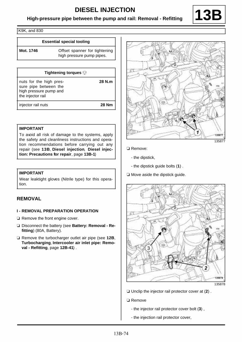
13B-74
DIESEL INJECTIONHigh-pressure pipe between the pump and rail: Removal - Refitting
K9K, and 830
13B
REMOVAL
I - REMOVAL PREPARATION OPERATION
a Remove the front engine cover.
a Disconnect the battery (see Battery: Removal - Re-fitting) (80A, Battery).
a Remove the turbocharger outlet air pipe (see 12B,Turbocharging, Intercooler air inlet pipe: Remo-val - Refitting, page 12B-41) .
a Remove:
- the dipstick,
- the dipstick guide bolts (1) .
a Move aside the dipstick guide.
a Unclip the injector rail protector cover at (2) .
a Remove
- the injector rail protector cover bolt (3) ,
- the injection rail protector cover,
Essential special tooling
Mot. 1746 Offset spanner for tighteninghigh pressure pump pipes.
Tightening torquesm
nuts for the high pres-sure pipe between thehigh pressure pump andthe injector rail
28 N.m
injector rail nuts 28 Nm
IMPORTANT
To avoid all risk of damage to the systems, applythe safety and cleanliness instructions and opera-tion recommendations before carrying out anyrepair (see 13B, Diesel injection, Diesel injec-tion: Precautions for repair, page 13B-1)
IMPORTANT
Wear leaktight gloves (Nitrile type) for this opera-tion.
135877
135878
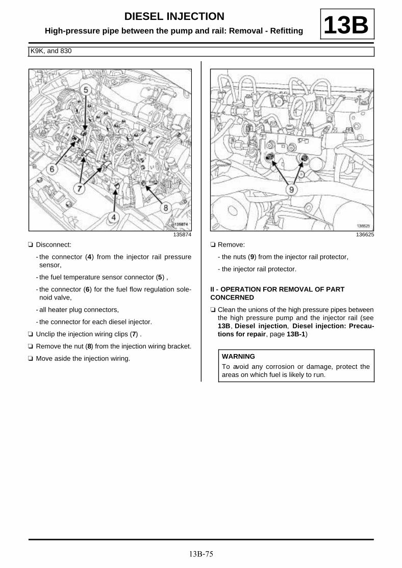
13B-75
DIESEL INJECTIONHigh-pressure pipe between the pump and rail: Removal - Refitting
K9K, and 830
13B
a Disconnect:
- the connector (4) from the injector rail pressuresensor,
- the fuel temperature sensor connector (5) ,
- the connector (6) for the fuel flow regulation sole-noid valve,
- all heater plug connectors,
- the connector for each diesel injector.
a Unclip the injection wiring clips (7) .
a Remove the nut (8) from the injection wiring bracket.
a Move aside the injection wiring.
a Remove:
- the nuts (9) from the injector rail protector,
- the injector rail protector.
II - OPERATION FOR REMOVAL OF PART CONCERNED
a Clean the unions of the high pressure pipes betweenthe high pressure pump and the injector rail (see13B, Diesel injection, Diesel injection: Precau-tions for repair, page 13B-1)
135874 136625
WARNING
To avoid any corrosion or damage, protect theareas on which fuel is likely to run.
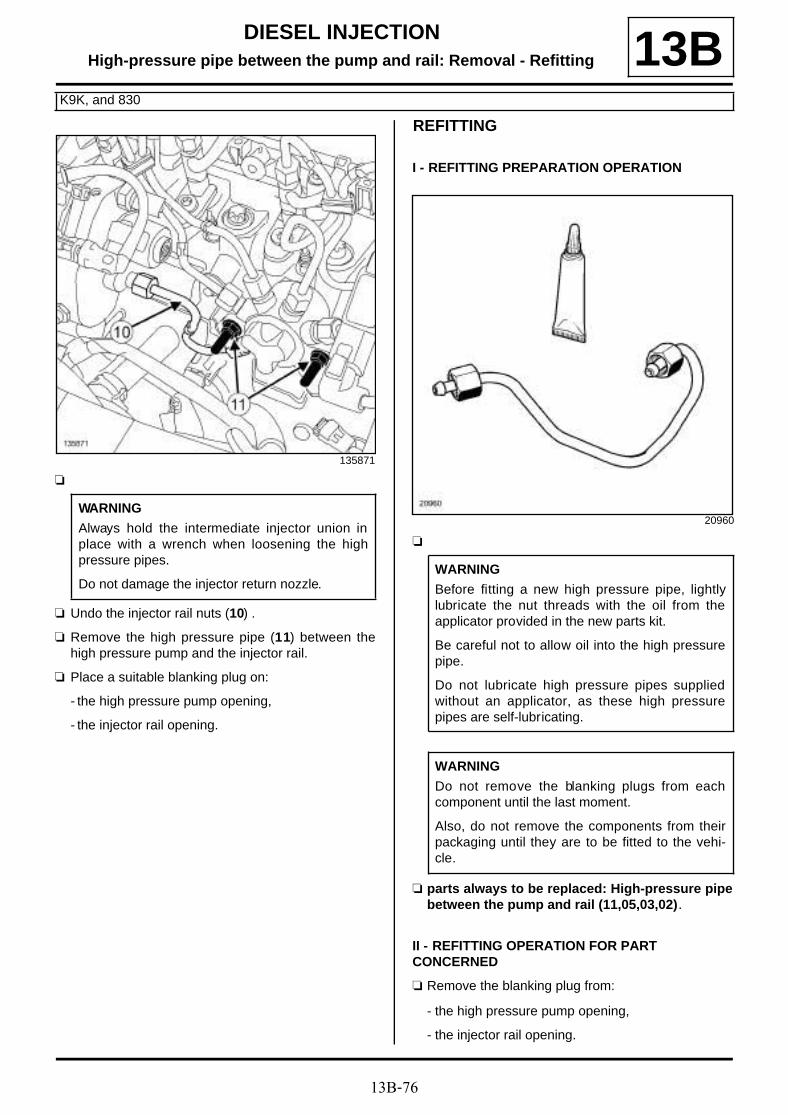
13B-76
DIESEL INJECTIONHigh-pressure pipe between the pump and rail: Removal - Refitting
K9K, and 830
13B
a
a Undo the injector rail nuts (10) .
a Remove the high pressure pipe (11) between thehigh pressure pump and the injector rail.
a Place a suitable blanking plug on:
- the high pressure pump opening,
- the injector rail opening.
REFITTING
I - REFITTING PREPARATION OPERATION
a
a parts always to be replaced: High-pressure pipebetween the pump and rail (11,05,03,02).
II - REFITTING OPERATION FOR PART CONCERNED
a Remove the blanking plug from:
- the high pressure pump opening,
- the injector rail opening.
135871
WARNING
Always hold the intermediate injector union inplace with a wrench when loosening the highpressure pipes.
Do not damage the injector return nozzle.
20960
WARNING
Before fitting a new high pressure pipe, lightlylubricate the nut threads with the oil from theapplicator provided in the new parts kit.
Be careful not to allow oil into the high pressurepipe.
Do not lubricate high pressure pipes suppliedwithout an applicator, as these high pressurepipes are self-lubricating.
WARNING
Do not remove the blanking plugs from eachcomponent until the last moment.
Also, do not remove the components from theirpackaging until they are to be fitted to the vehi-cle.

13B-77
DIESEL INJECTIONHigh-pressure pipe between the pump and rail: Removal - Refitting
K9K, and 830
13Ba Fit the new high pressure pipe between the injector
rail and the high pressure pump.
a Screw on the nuts for the high pressure pipebetween the high pressure pump and the injector railby hand without tightening, starting at the injector railend.
a Using the tool (Mot. 1746), torque tighten the nutsfor the high pressure pipe between the highpressure pump and the injector rail (28 N.m).
a Torque tighten the injector rail nuts (28 Nm).
III - FINAL OPERATION
a Refit the injector rail protector.
a Fit the injection wiring.
a Refit the injection wiring bracket nut.
a Clip on the injection wiring clip.
a Connect:
- the connector for each diesel injector,
- all heater plug connectors,
- the connector for the fuel flow regulation solenoidvalve,
- the fuel temperature sensor connector,
- the injector rail pressure sensor connector.
a Refit:
- the injector rail protector cover,
- the injection rail protector cover bolt.
a Clip on the injector rail protector cover plate.
a Fit the dipstick guide tube.
a Refit:
- the dipstick guide bolts,
- the dipstick.
a Refit the turbocharger air outlet pipe (see 12B, Tur-bocharging, Intercooler air inlet pipe: Removal -Refitting, page 12B-41) .
a Connect the battery (see Battery : Removal - Refit-ting) (80A, Battery).
a Refit the engine cover.
a Reprime the fuel circuit using the manual primingpump.
a Check that there are no diesel leaks (see High pres-sure pipe: Checking) .

13B-78
DIESEL INJECTIONHigh-pressure pipe between the pump and rail: Removal - Refitting
K9K, and 832
13B
REMOVAL
I - REMOVAL PREPARATION OPERATION
a Disconnect the battery (see Battery : Removal -Refitting) (80A, Battery).
a Remove the front engine cover.
a Disconnect the turbocharger pressure sensor con-nector (1) .
a Unclip the wiring for the turbocharging pressure sen-sor from the intercooler air outlet pipe at (2) .
a Loosen the damper valve clip (3) from the intercoo-ler air outlet pipe.
a Disconnect the intercooler air outlet pipe from thedamper valve.
a Remove the intercooler air outlet pipe from the dam-per valve.
Essential special tooling
Mot. 1566 Spanner for removing highpressure pipes.
Mot. 1746 Offset spanner for tighteninghigh pressure pump pipes.
Tightening torquesm
nuts for the high pres-sure pipe between thehigh pressure pump andthe injector rail
28 N.m
intercooler air outletpipe clip on the dampervalve
5.5 N.m
IMPORTANT
To avoid all risk of damage to the systems, applythe safety and cleanliness instructions and opera-tion recommendations before carrying out anyrepair (see 13B, Diesel injection, Diesel injec-tion: Precautions for repair, page 13B-1) .
IMPORTANT
Wear leaktight gloves (Nitrile type) for this opera-tion.
134215

13B-79
DIESEL INJECTIONHigh-pressure pipe between the pump and rail: Removal - Refitting
K9K, and 832
13B
a Disconnect:
- the damper valve connector (4) ,
- the connector (5) from the camshaft position sen-sor.
a Unclip the damper valve wiring from the injector railprotector cover plate at (6) .
a Remove the turbocharger outlet air pipe (see 12B,Turbocharging, Intercooler air inlet pipe: Remo-val - Refitting, page 12B-41) .
a Unclip the injector rail protector cover at (7) .
a Remove:
- the injector rail protector cover bolt (8) ,
- the injector rail protector cover nut (9) ,
- the injector rail protector cover,
a Remove:
- the dipstick,
- the dipstick guide bolts (20) .
a Move aside the dipstick guide.
121889
134699
134703
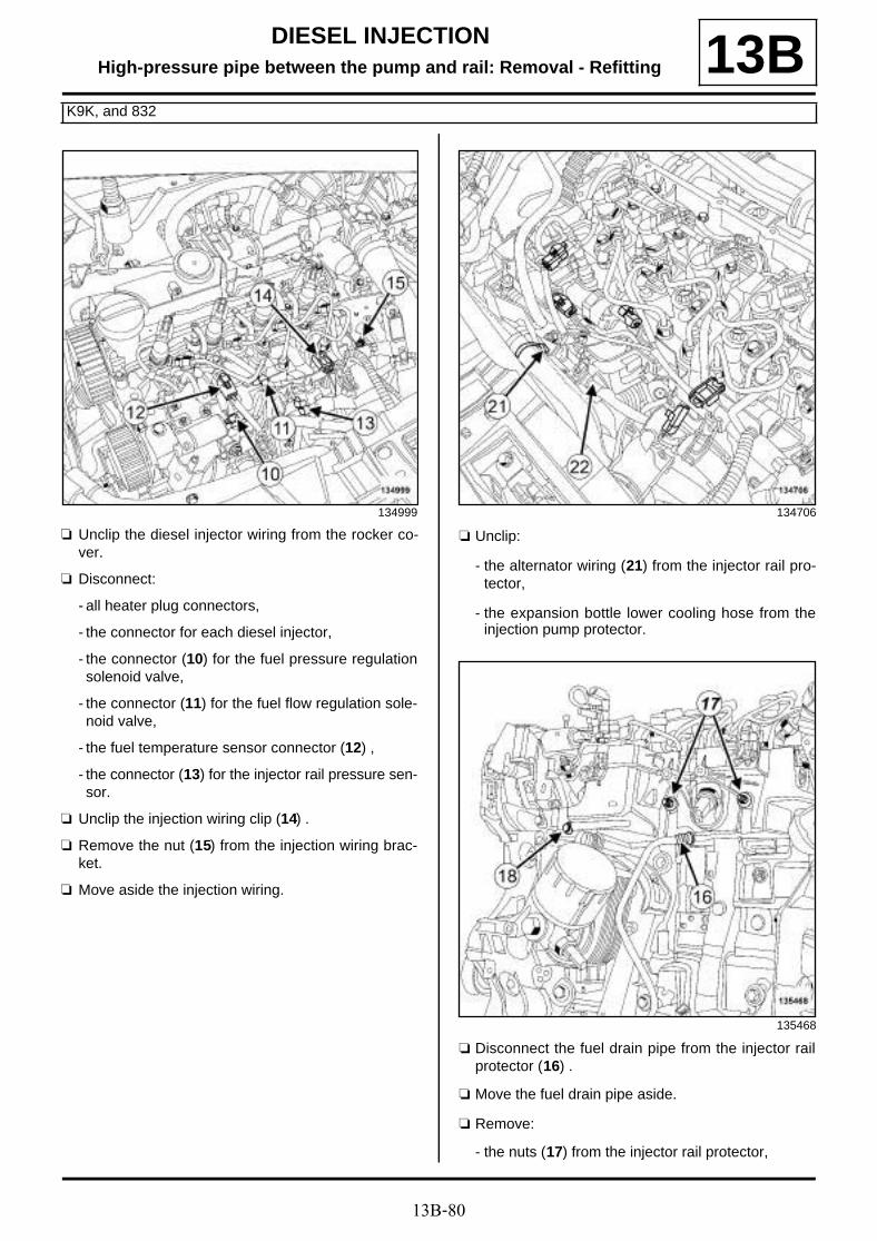
13B-80
DIESEL INJECTIONHigh-pressure pipe between the pump and rail: Removal - Refitting
K9K, and 832
13B
a Unclip the diesel injector wiring from the rocker co-ver.
a Disconnect:
- all heater plug connectors,
- the connector for each diesel injector,
- the connector (10) for the fuel pressure regulationsolenoid valve,
- the connector (11) for the fuel flow regulation sole-noid valve,
- the fuel temperature sensor connector (12) ,
- the connector (13) for the injector rail pressure sen-sor.
a Unclip the injection wiring clip (14) .
a Remove the nut (15) from the injection wiring brac-ket.
a Move aside the injection wiring.
a Unclip:
- the alternator wiring (21) from the injector rail pro-tector,
- the expansion bottle lower cooling hose from theinjection pump protector.
a Disconnect the fuel drain pipe from the injector railprotector (16) .
a Move the fuel drain pipe aside.
a Remove:
- the nuts (17) from the injector rail protector,
134999 134706
135468

13B-81
DIESEL INJECTIONHigh-pressure pipe between the pump and rail: Removal - Refitting
K9K, and 832
13B- the injector rail protector bolt (18) ,
- the injector rail protector.
II - OPERATION FOR REMOVAL OF PART CONCERNED
a Clean the unions of the high pressure pipe betweenthe high pressure pump and the injector rail (see13B, Diesel injection, Diesel injection: Precau-tions for repair, page 13B-1) .
a Remove the high pressure pipe between the highpressure pump and the injector rail (19) .
a Place a suitable blanking plug on:
- the high pressure pump opening,
- the injector rail opening.
REFITTING
I - REFITTING PREPARATION OPERATION
a
a parts always to be replaced: High-pressure pipebetween the pump and rail (11,05,03,02).
II - REFITTING OPERATION FOR PART CONCERNED
a Remove the blanking plugs from:
- the high pressure pump opening,
- the injector rail opening.
a Fit the new high pressure pipe between the injectorrail and the high pressure pump.
WARNING
To avoid any corrosion or damage, protect theareas on which fuel is likely to run.
135005
Note:
It is essential to use a spanner to hold the highpressure pump intermediate union when loose-ning the high pressure pipe.
20960
WARNING
Before fitting a new high pressure pipe, lightlylubricate the nut threads with the oil from theapplicator provided in the new parts kit.
Be careful not to allow oil into the high pressurepipe.
Do not lubricate high pressure pipes suppliedwithout an applicator, as these high pressurepipes are self-lubricating.
Note:
If the set of new pipes does not contain an appli-cator, do not lubricate the threads of the highpressure pipe (as they are self-lubricating pipes).
13B-82
DIESEL INJECTIONHigh-pressure pipe between the pump and rail: Removal - Refitting
K9K, and 832
13Ba Screw on by hand, without tightening, until contact is
made with the nuts of the high pressure pipebetween the high pressure pump and the injectorrail, starting at the injector rail end.
a Using the tool (Mot. 1566) or the tool (Mot. 1746),torque tighten the nuts for the high pressure pipebetween the high pressure pump and the injec-tor rail (28 N.m).
III - FINAL OPERATION
a Refit the injector rail protector.
a Fit the fuel drain pipe.
a Connect the fuel drain pipe to the injector rail protec-tor.
a Fit the injection wiring.
a Refit the injection wiring bracket nut.
a Clip on the injection wiring clip.
a Refit:
- injector rail pressure sensor connector,
- the fuel temperature sensor connector,
- the connector for the fuel flow regulation solenoidvalve,
- the connector for the fuel pressure regulation sole-noid valve,
- the connector for each diesel injector,
- all heater plug connectors.
a Clip the diesel injector wiring onto the rocker cover.
a Fit the dipstick guide tube.
a Refit:
- the dipstick guide bolts,
- the dipstick,
- the injection rail protector cover,
a Clip on the injector rail protector cover.
a Refit the turbocharger air outlet pipe (see 12B, Tur-bocharging, Intercooler air inlet pipe: Removal -Refitting, page 12B-41) .
a Fit the intercooler air outlet pipe.
a Connect the intercooler air outlet pipe on the dampervalve.
a Torque tighten the intercooler air outlet pipe clipon the damper valve (5.5 N.m).
a Clip the turbocharger pressure sensor wiring ontothe intercooler air outlet pipe.
a Connect the turbocharger pressure sensor connec-tor.
a Clip the wiring for the damper valve onto the injectorrail protector cover plate.
a Connect:
- the camshaft position sensor connector,
- the connector to the damper flap.
a Refit the engine cover.
a Connect the battery (see Battery : Removal - Refit-ting) (80A, Battery).
a Check that there are no diesel leaks.

13B-83
DIESEL INJECTIONHigh-pressure pipe between the pump and rail: Removal - Refitting
K9K, and 834
13B
REMOVAL
I - REMOVAL PREPARATION OPERATION
a Disconnect the battery (see Battery : Removal -Refitting) (80A, Battery).
a Remove the front engine cover.
a Remove:
- the bolt (1) for the intermediate air pipe betweenthe turbocharger and the intercooler,
- the nut (2) for the intermediate air pipe between theturbocharger and the intercooler.
a Pull the clip (3) from the turbocharger air outlet pipe.
a Remove the intermediate air pipe between the tur-bocharger and the intercooler from the turbochargerair outlet pipe.
a Remove:
- the bolt (4) from the retaining bracket of the inter-mediate air pipe between the turbocharger and theintercooler,
- the retaining bracket for the intermediate air pipebetween the turbocharger and the intercooler.
- the seal from the turbocharger air outlet pipe.
Essential special tooling
Mot. 1566 Spanner for removing highpressure pipes.
Tightening torquesm
nut for the high pressurepipe between the highpressure pump and theinjector rail on the highpressure pump
28 N.m
nut for the high pressurepipe between the highpressure pump and theinjector rail on the injec-tor rail
28 N.m
IMPORTANT
Wear leaktight gloves (Nitrile type) for this opera-tion.
IMPORTANT
To avoid all risk of damage to the systems, applythe safety and cleanliness instructions and opera-tion recommendations before carrying out anyrepair (see 13B, Diesel injection, Diesel injec-tion: Precautions for repair, page 13B-1) .
WARNING
To avoid any corrosion or damage, protect theareas on which fuel is likely to run.
137183

13B-84
DIESEL INJECTIONHigh-pressure pipe between the pump and rail: Removal - Refitting
K9K, and 834
13B
a Disconnect the turbocharger pressure sensor con-nector (5) .
a Unclip the cable for the turbocharging pressure sen-sor from the intercooler air outlet pipe (6) .
a Pull the clip (7) from the intercooler air outlet pipe.
a Move the intercooler outlet air pipe to one side.
a Remove the seal from the intercooler air outlet pipe.
a Unclip the wiring for the damper valve from the injec-tor rail protector at (8) .
a Unclip the injector rail protector cover at (9) .
a Remove:
- the bolts (10) from the injector rail protector coverplate,
- the injector rail protector.
II - OPERATION FOR REMOVAL OF PART CONCERNED
a Clean the nuts of the high pressure pipe betweenthe high pressure pump and the injector rail (see13B, Diesel injection, Diesel injection: Precau-tions for repair, page 13B-1) .
137184 137185
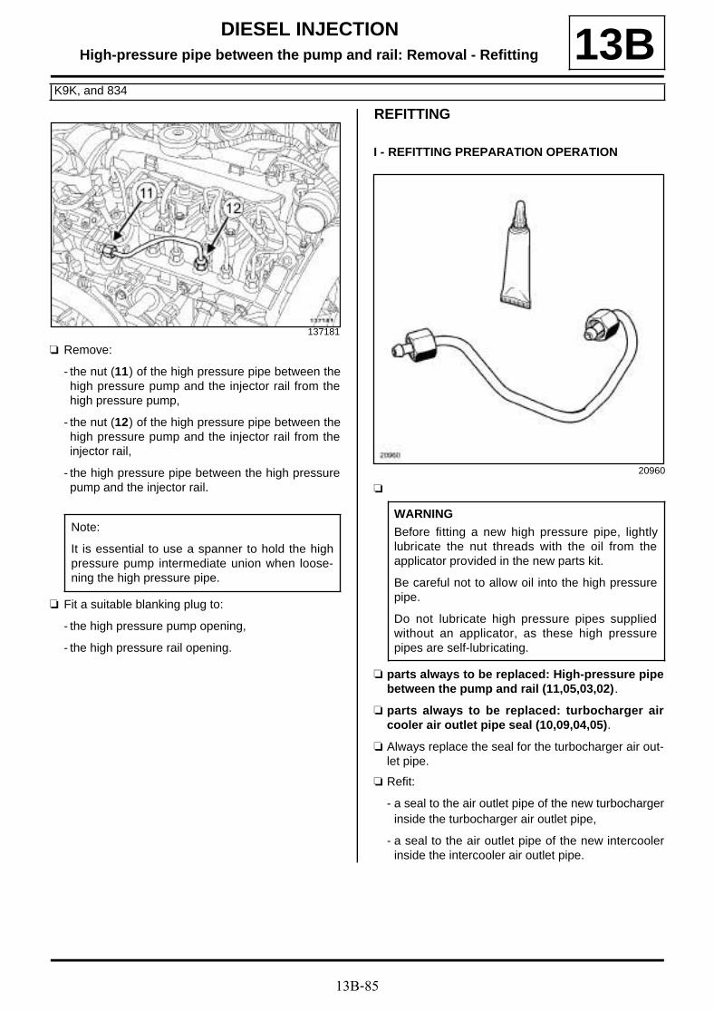
13B-85
DIESEL INJECTIONHigh-pressure pipe between the pump and rail: Removal - Refitting
K9K, and 834
13B
a Remove:
- the nut (11) of the high pressure pipe between thehigh pressure pump and the injector rail from thehigh pressure pump,
- the nut (12) of the high pressure pipe between thehigh pressure pump and the injector rail from theinjector rail,
- the high pressure pipe between the high pressurepump and the injector rail.
a Fit a suitable blanking plug to:
- the high pressure pump opening,
- the high pressure rail opening.
REFITTING
I - REFITTING PREPARATION OPERATION
a
a parts always to be replaced: High-pressure pipebetween the pump and rail (11,05,03,02).
a parts always to be replaced: turbocharger aircooler air outlet pipe seal (10,09,04,05).
a Always replace the seal for the turbocharger air out-let pipe.
a Refit:
- a seal to the air outlet pipe of the new turbochargerinside the turbocharger air outlet pipe,
- a seal to the air outlet pipe of the new intercoolerinside the intercooler air outlet pipe.
137181
Note:
It is essential to use a spanner to hold the highpressure pump intermediate union when loose-ning the high pressure pipe.
20960
WARNING
Before fitting a new high pressure pipe, lightlylubricate the nut threads with the oil from theapplicator provided in the new parts kit.
Be careful not to allow oil into the high pressurepipe.
Do not lubricate high pressure pipes suppliedwithout an applicator, as these high pressurepipes are self-lubricating.

13B-86
DIESEL INJECTIONHigh-pressure pipe between the pump and rail: Removal - Refitting
K9K, and 834
13BII - REFITTING OPERATION FOR PART CONCERNED
a Remove the blanking plug from:
- the high pressure pump opening,
- the high pressure rail opening.
a Fit a high-pressure pipe between the high pressurepump and the new injector rail.
a Screw on by hand, without tightening, until contact ismade by the nuts of the high pressure pipe betweenthe high pressure pump and the injector rail, startingat the injector rail end.
a Tighten to torque:
- the nut for the high pressure pipe between thehigh pressure pump and the injector rail on thehigh pressure pump (28 N.m) using the tool (Mot.1566),
- the nut for the high pressure pipe between thehigh pressure pump and the injector rail on theinjector rail (28 N.m) using the tool (Mot. 1566).
III - FINAL OPERATION
a Refit:
- the injector rail protector,
- the bolts for the injector rail protector cover plate.
a Clip the injector rail protector cover into place.
a Clip on the wiring for the damper valve.
a Refit the clip for the intercooler air outlet pipe.
a Clip the intercooler air outlet pipe onto the dampervalve.
a Clip the turbocharger pressure sensor cable ontothe intercooler air outlet pipe.
a Connect the turbocharger pressure sensor connec-tor.
a Refit:
- the retaining bracket for the intermediate air pipebetween the turbocharger and the intercooler,
- the bolt for the retaining bracket of the intermediateair pipe between the turbocharger and the intercoo-ler.
a Refit the clip for the turbocharger air outlet pipe.
a Clip the intermediate air pipe between the turbochar-ger and the intercooler onto the turbocharger air out-let pipe.
a Refit:
- the bolt for the intermediate air pipe between theturbocharger and the intercooler,
- the nut for the intermediate air pipe between theturbocharger and the intercooler,
- the engine cover.
a Connect the battery (see Battery : Removal - Refit-ting) (80A, Battery).
Note:
If the set of new pipes does not contain an appli-cator, do not lubricate the threads of the highpressure pipe (as they are self-lubricating pipes).
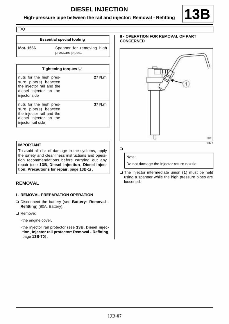
13B-87
DIESEL INJECTIONHigh-pressure pipe between the rail and injector: Removal - Refitting
F9Q
13B
REMOVAL
I - REMOVAL PREPARATION OPERATION
a Disconnect the battery (see Battery : Removal -Refitting) (80A, Battery).
a Remove:
- the engine cover,
- the injector rail protector (see 13B, Diesel injec-tion, Injector rail protector: Removal - Refitting,page 13B-70) .
II - OPERATION FOR REMOVAL OF PART CONCERNED
a
a The injector intermediate union (1) must be heldusing a spanner while the high pressure pipes areloosened.
Essential special tooling
Mot. 1566 Spanner for removing highpressure pipes.
Tightening torquesm
nuts for the high pres-sure pipe(s) betweenthe injector rail and thediesel injector on theinjector side
27 N.m
nuts for the high pres-sure pipe(s) betweenthe injector rail and thediesel injector on theinjector rail side
37 N.m
IMPORTANT
To avoid all risk of damage to the systems, applythe safety and cleanliness instructions and opera-tion recommendations before carrying out anyrepair (see 13B, Diesel injection, Diesel injec-tion: Precautions for repair, page 13B-1) .
1327
Note:
Do not damage the injector return nozzle.

13B-88
DIESEL INJECTIONHigh-pressure pipe between the rail and injector: Removal - Refitting
F9Q
13B
a Clean the nuts of the high pressure pipe(s) betweenthe injector rail and the diesel fuel injector (see 13B,Diesel injection, Diesel injection: Precautions forrepair, page 13B-1) .
a Remove:
- from the injector(s), the nut for the high pressure pi-pe(s) between the injector rail and the diesel fuelinjector using the tool (Mot. 1566),
- from the injector rail, the nut for the high pressurepipe(s) between the injector rail and the diesel fuelinjector using the tool (Mot. 1566),
- the high pressure pipe(s) between the injector railand the diesel injector.
a Fit blanking plugs on:
- the opening(s) of the diesel fuel injector(s),
- the opening(s) on the injector rail.
REFITTING
I - REFITTING PREPARATION OPERATION
a parts always to be replaced: High-pressure pipebetween the rail and injector (11,05,03,01).
a
II - REFITTING OPERATION FOR PART CONCERNED
a Remove the blanking plugs on:
- the opening(s) of the diesel fuel injector(s),
- the opening(s) on the injector rail.
111838
WARNING
Prepare for the flow of fluid, and protect the sur-rounding components.
WARNING
To prevent impurities from entering the circuit,place protective plugs on all fuel circuit compo-nents exposed to the open air.
20960
WARNING
Before fitting a new high pressure pipe, lightlylubricate the nut threads with the oil from theapplicator provided in the new parts kit.
Be careful not to allow oil into the high pressurepipe.
Do not lubricate high pressure pipes suppliedwithout an applicator, as these high pressurepipes are self-lubricating.
WARNING
Do not remove the blanking plugs from eachcomponent until the last moment.
Also, do not remove the components from theirpackaging until they are to be fitted to the vehi-cle.

13B-89
DIESEL INJECTIONHigh-pressure pipe between the rail and injector: Removal - Refitting
F9Q
13Ba Refit one or more new high pressure pipes between
the injector rail and the diesel fuel injector.
a Using the (Mot. 1566), tighten to torque:
- the nuts for the high pressure pipe(s) betweenthe injector rail and the diesel injector on the in-jector side (27 N.m),
- the nuts for the high pressure pipe(s) betweenthe injector rail and the diesel injector on the in-jector rail side (37 N.m).
III - FINAL OPERATION
a Refit:
- the injector rail protector (see 13B, Diesel injec-tion, Injector rail protector: Removal - Refitting,page 13B-70) ,
- the engine cover.
a Connect the battery (see Battery : Removal - Refit-ting) (80A, Battery).

13B-90
DIESEL INJECTIONHigh-pressure pipe between the rail and injector: Removal - Refitting
K9K, and 832
13B
REMOVAL
I - REMOVAL PREPARATION OPERATION
a Disconnect the battery (see Battery : Removal -Refitting) (80A, Battery).
a Remove the front engine cover.
a Disconnect the turbocharger pressure sensor con-nector (1) .
a Unclip the wiring for the turbocharging pressure sen-sor from the intercooler air outlet pipe at (2) .
a Undo the damper valve clip (3) from the intercoolerair outlet pipe.
a Disconnect the intercooler air outlet pipe from thedamper valve.
a Separate the intercooler air outlet pipe from thedamper valve.
Essential special tooling
Mot. 1566 Spanner for removing highpressure pipes.
Mot. 1746 Offset spanner for tighteninghigh pressure pump pipes.
Tightening torquesm
nuts for the high pres-sure pipe(s) betweenthe injector rail and thediesel injector(s)
28 N.m
injector rail nuts 28 N.m
nuts for the high pres-sure pipes between theinjector rail and the die-sel injectors
28 N.m
clip for the intercoolerair outlet pipe on thedamper valve
5.5 N.m
IMPORTANT
To avoid all risk of damage to the systems, applythe safety and cleanliness instructions and opera-tion recommendations before carrying out anyrepair (see 13B, Diesel injection, Diesel injec-tion: Precautions for repair, page 13B-1) .
IMPORTANT
Wear leaktight gloves (Nitrile type) for this opera-tion.
134215

13B-91
DIESEL INJECTIONHigh-pressure pipe between the rail and injector: Removal - Refitting
K9K, and 832
13B
a Disconnect:
- the damper valve connector (4) ,
- the connector (5) from the camshaft position sen-sor.
a Unclip the damper valve wiring from the injector railprotector cover plate at (6) .
a Remove the turbocharger outlet air pipe (see 12B,Turbocharging, Intercooler air inlet pipe: Remo-val - Refitting, page 12B-41) .
a Unclip the injector rail protector cover at (7) .
a Remove:
- the injector rail protector cover bolt (8) ,
- the injector rail protector cover nut (9) ,
- the injector rail protector cover,
- the dipstick,
- the dipstick guide tube bolts.
a Move aside the dipstick guide.
a Clean the high pressure pipe unions between the railand the injectors (see 13B, Diesel injection, Dieselinjection: Precautions for repair, page 13B-1) .
II - OPERATION FOR REMOVAL OF PART CONCERNED
1 - Removing one, two or three high pressure pipes
a
a Loosen the nuts for the high pressure pipe betweenthe injector rail and the diesel fuel injector(s), usingthe tool (Mot. 1566).
a Remove:
- the nut(s) for the high pressure pipe(s) between theinjector rail and the diesel fuel injector(s) on the in-jector rail side,
121889
134699
1327
WARNING
Always hold the intermediate injector union inplace with a wrench when loosening the highpressure pipes.
Do not damage the injector return nozzle.
WARNING
To avoid any corrosion or damage, protect theareas on which fuel is likely to run.

13B-92
DIESEL INJECTIONHigh-pressure pipe between the rail and injector: Removal - Refitting
K9K, and 832
13B- the nut(s) for the high pressure pipe(s) between theinjector rail and the diesel fuel injector(s) on the in-jector side,
- the high pressure pipe(s) between the injector railand the diesel fuel injector(s) concerned.
a Fit suitable blanking plugs on:
- the opening(s) on the injector rail,
- the opening of the diesel injector(s).
2 - Removing the four high pressure pipes
a Unclip the diesel fuel injector wiring from the rockercover.
a Disconnect:
- all heater plug connectors,
- the connector for each diesel injector,
- the connector (10) for the fuel pressure regulationsolenoid valve,
- the connector (11) for the fuel flow regulation sole-noid valve,
- the fuel temperature sensor connector (12) ,
- the connector (13) for the injector rail pressure sen-sor.
a Unclip the injection wiring clip (14) .
a Remove the nut (15) from the injection wiring brac-ket.
a Move aside the injection wiring.
a Unclip:
- the alternator wiring from the injector rail protector,
- the coolant hose from the injection pump protector
a Unclip the expansion bottle lower cooling hose fromthe injection pump protector.
a Disconnect the fuel drain pipe from the injector railprotector (16) .
a Move the fuel drain pipe aside.
a Remove:
- the nuts (17) from the injector rail protector,
- the injector rail protector bolt (18) ,
- the injector rail protector.
134999
135468
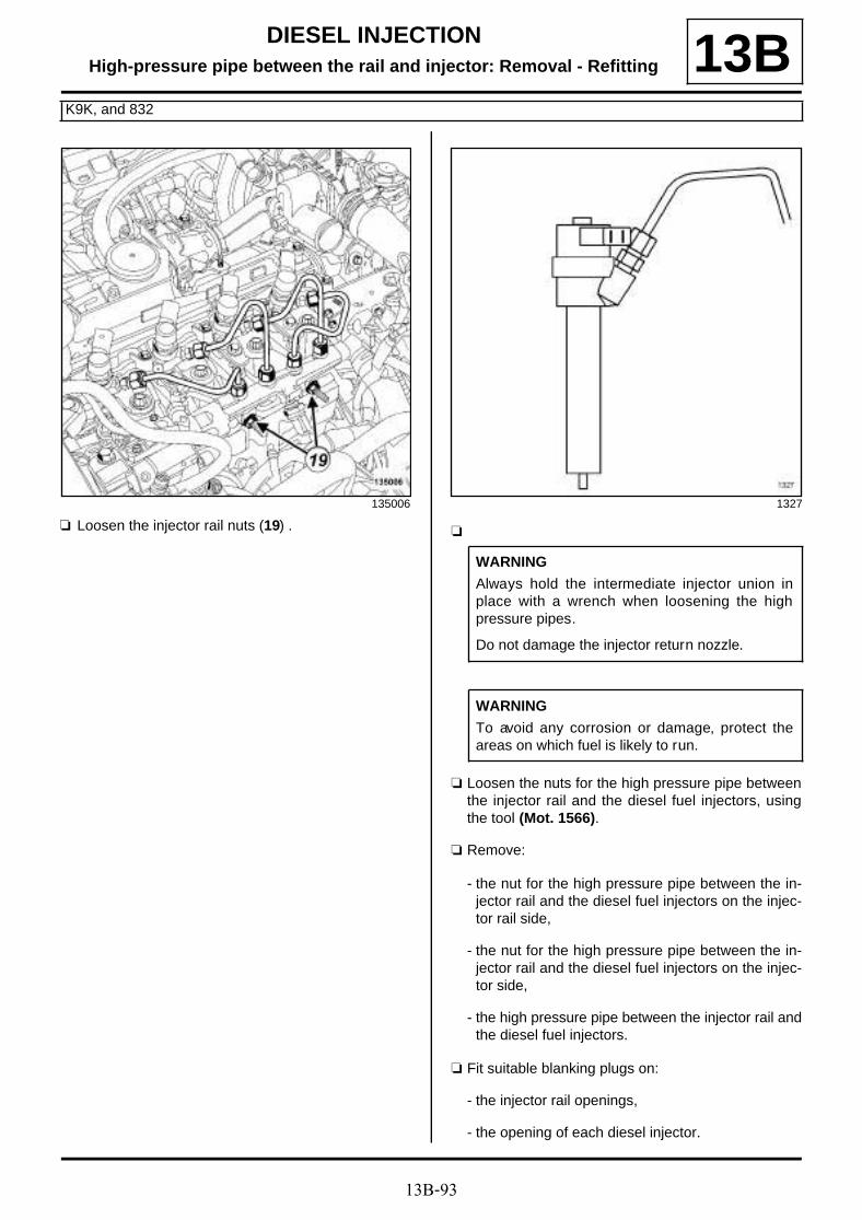
13B-93
DIESEL INJECTIONHigh-pressure pipe between the rail and injector: Removal - Refitting
K9K, and 832
13B
a Loosen the injector rail nuts (19) .a
a Loosen the nuts for the high pressure pipe betweenthe injector rail and the diesel fuel injectors, usingthe tool (Mot. 1566).
a Remove:
- the nut for the high pressure pipe between the in-jector rail and the diesel fuel injectors on the injec-tor rail side,
- the nut for the high pressure pipe between the in-jector rail and the diesel fuel injectors on the injec-tor side,
- the high pressure pipe between the injector rail andthe diesel fuel injectors.
a Fit suitable blanking plugs on:
- the injector rail openings,
- the opening of each diesel injector.
135006 1327
WARNING
Always hold the intermediate injector union inplace with a wrench when loosening the highpressure pipes.
Do not damage the injector return nozzle.
WARNING
To avoid any corrosion or damage, protect theareas on which fuel is likely to run.

13B-94
DIESEL INJECTIONHigh-pressure pipe between the rail and injector: Removal - Refitting
K9K, and 832
13BREFITTING
I - REFITTING PREPARATION OPERATION
a
a parts always to be replaced: High-pressure pipebetween the rail and injector (11,05,03,01).
II - REFITTING OPERATION FOR PART CONCERNED
1 - Refitting one, two or three high pressure pipes
a Remove the blanking plug
- the injector rail opening(s),
- the opening of the diesel injector(s).
a Screw on the nuts for the high pressure pipe(s)between the injector rail and the diesel injector(s) byhand without tightening, starting on the injector railside.
a Using the tool (Mot. 1566) or the tool (Mot. 1746),torque tighten the nuts for the high pressure pi-pe(s) between the injector rail and the diesel in-jector(s) (28 N.m).
2 - Refitting the four high pressure pipes
a Remove the blanking plug
- the injector rail openings,
- the opening of each diesel injector.
a Screw on the nuts for the high pressure pipe(s)between the injector rail and the diesel injector(s) byhand without tightening, starting on the injector railside.
a Tighten to torque:
- the injector rail nuts (28 N.m),
- using the tool (Mot. 1566) or the tool (Mot. 1746)the nuts for the high pressure pipes betweenthe injector rail and the diesel injectors (28N.m).
a Refit the injector rail protector.
a Clip:
- the expansion bottle lower cooling hose onto the in-jection pump protector,
- the alternator wiring onto the injector rail protector.
a Fit the fuel drain pipe.
a Connect the fuel drain pipe to the injector rail protec-tor.
a Fit the injection wiring.
a Refit the injection wiring bracket nut.
a Clip on the injection wiring clip.
a Refit:
- injector rail pressure sensor connector,
- the fuel temperature sensor connector,
20960
WARNING
Before fitting a new high pressure pipe, lightlylubricate the nut threads with the oil from theapplicator provided in the new parts kit.
Be careful not to allow oil into the high pressurepipe.
Do not lubricate high pressure pipes suppliedwithout an applicator, as these high pressurepipes are self-lubricating.
WARNING
Do not remove the blanking plugs from eachcomponent until the last moment.
Also, do not remove the components from theirpackaging until they are to be fitted to the vehi-cle.

13B-95
DIESEL INJECTIONHigh-pressure pipe between the rail and injector: Removal - Refitting
K9K, and 832
13B- the connector for the fuel flow regulation solenoidvalve,
- the connector for the fuel pressure regulation sole-noid valve,
- the connector for each diesel injector,
- all heater plug connectors.
a Clip the diesel injector wiring onto the rocker cover.
III - FINAL OPERATION
a Fit the dipstick guide tube.
a Refit:
- the dipstick guide bolts,
- the dipstick,
- the injection rail protector cover,
a Clip on the injector rail protector cover.
a Refit the turbocharger air outlet pipe (see 12B, Tur-bocharging, Intercooler air inlet pipe: Removal -Refitting, page 12B-41) .
a Fit the intercooler air outlet pipe.
a Connect the intercooler air outlet pipe on the dampervalve.
a Torque tighten the clip for the intercooler air out-let pipe on the damper valve (5.5 N.m).
a Clip the turbocharger pressure sensor wiring ontothe intercooler air outlet pipe.
a Connect the turbocharger pressure sensor connec-tor.
a Clip the wiring for the damper valve onto the injectorrail protector cover plate.
a Connect:
- the camshaft position sensor connector,
- the connector to the damper flap.
a Refit the engine cover.
a Connect the battery (see Battery : Removal - Refit-ting) (80A, Battery).
a Check that there are no diesel leaks.

13B-96
DIESEL INJECTIONHigh-pressure pipe between the rail and injector: Removal - Refitting
K9K, and 830
13B
REMOVAL
I - REMOVAL PREPARATION OPERATION
a Disconnect the battery (see Battery: Removal - Re-fitting) (80A, Battery).
a Remove:
- the engine cover,
- the turbocharger air outlet pipe (see 12B, Turbo-charging, Intercooler air inlet pipe: Removal -Refitting, page 12B-41) .
a Remove:
- the dipstick,
- the dipstick guide bolts (1) .
a Move aside the dipstick guide.
a Unclip the injector rail protector cover at (2) .
a Remove:
- the injector rail protector cover bolt (3) ,
- the injection rail protector cover,
Essential special tooling
Mot. 1566 Spanner for removing highpressure pipes.
Mot. 1746 Offset spanner for tighteninghigh pressure pump pipes.
Tightening torquesm
nuts for the high pres-sure pipe(s) betweenthe injector rail and thediesel injector(s)
28 N.m
injector rail nuts 28 N.m
nuts for the high pres-sure pipes between theinjector rail and the die-sel injectors
28 N.m
IMPORTANT
To avoid all risk of damage to the systems, applythe safety and cleanliness instructions and opera-tion recommendations before carrying out anyrepair (see 13B, Diesel injection, Diesel injec-tion: Precautions for repair, page 13B-1) .
IMPORTANT
Wear leaktight gloves (Nitrile type) for this opera-tion.
135877
135878

13B-97
DIESEL INJECTIONHigh-pressure pipe between the rail and injector: Removal - Refitting
K9K, and 830
13Ba Clean the high pressure pipe unions between the rail
and the diesel fuel injectors (see 13B, Diesel injec-tion, Diesel injection: Precautions for repair,page 13B-1) .
II - OPERATION FOR REMOVAL OF PART CONCERNED
1 - Removing one, two or three high pressure pipes
a
a Loosen the nuts for the high pressure pipe(s)between the injector rail and the diesel fuel injec-tor(s), using the tool (Mot. 1566).
a Remove:
- the nuts for the high pressure pipe(s) between theinjector rail and the diesel fuel injector(s) on the in-jector rail side,
- the nuts for the high pressure pipe(s) between theinjector rail and the diesel fuel injector(s) on the in-jector side,
- the high pressure pipes between the injector railand the diesel injectors concerned.
a Fit suitable blanking plugs on:
- the opening(s) on the injector rail,
- the opening of the diesel fuel injector(s).
2 - Removing the four high pressure pipes
a Disconnect:
- the connector (4) from the injector rail pressuresensor,
- the fuel temperature sensor connector (5) ,
- the connector (6) for the fuel flow regulation sole-noid valve,
- all heater plug connectors,
- the connector for each diesel injector.
a Unclip the injection wiring clips (7) .
a Remove the nut (8) from the injection wiring bracket.
a Separate the injection wiring.
1327
WARNING
Always hold the intermediate injector union inplace with a wrench when loosening the highpressure pipes.
Do not damage the injector return nozzle.
WARNING
To avoid any corrosion or damage, protect theareas on which fuel is likely to run.
135874

13B-98
DIESEL INJECTIONHigh-pressure pipe between the rail and injector: Removal - Refitting
K9K, and 830
13B
a Remove:
- the nuts (9) from the injector rail protector,
- the injector rail protector.
a Undo the injector rail nuts (10) .
a
a Undo the high pressure pipe nuts between the railand the injector using the (Mot. 1566).
a Remove:
- the nut for the high pressure pipes between the in-jector rail and the diesel fuel injectors on the injec-tor rail side,
- the nut for the high pressure pipes between the in-jector rail and the diesel fuel injectors on the injec-tor side,
- the high pressure pipes between the injector railand the diesel fuel injectors concerned.
a Fit suitable blanking plugs on:
- the injector rail openings,
- the opening of each diesel injector.
136625
135859
1327
WARNING
Always hold the intermediate injector union inplace with a wrench when loosening the highpressure pipes.
Do not damage the injector return nozzle.
WARNING
To avoid any corrosion or damage, protect theareas on which fuel is likely to run.

13B-99
DIESEL INJECTIONHigh-pressure pipe between the rail and injector: Removal - Refitting
K9K, and 830
13BREFITTING
I - REFITTING PREPARATION OPERATION
a
a parts always to be replaced: High-pressure pipebetween the rail and injector (11,05,03,01).
II - REFITTING OPERATION FOR PART CONCERNED
1 - Refitting one, two or three high pressure pipes
a Remove the blanking plugs from:
- the injector rail opening(s),
- the opening of the diesel injector(s).
a Screw on the nuts for the high pressure pipe(s)between the injector rail and the diesel injector(s) byhand without tightening, starting on the injector railside.
a Using the tool (Mot. 1566) or the tool (Mot. 1746),torque tighten the nuts for the high pressure pi-pe(s) between the injector rail and the diesel in-jector(s) (28 N.m).
2 - Refitting the four high pressure pipes
a Remove the blanking plugs from:
- the injector rail openings,
- the opening of each diesel injector.
a Screw on the nuts for the high pressure pipe(s)between the injector rail and the diesel injector(s) byhand without tightening, starting on the injector railside.
a Torque tighten:
- the injector rail nuts (28 N.m),
- using the tool (Mot. 1566) or the tool (Mot. 1746)(Mot. 1566) (Mot. 1746) the nuts for the highpressure pipes between the injector rail and thediesel injectors (28 N.m).
a Refit the injector rail protector.
a Fit the injection wiring.
a Refit the injection wiring bracket nut.
a Clip on the injection wiring clip.
a Connect:
- the connector for each diesel injector,
- all heater plug connectors,
- the connector for the turbocharging fuel flow regu-lation solenoid valve,
- the fuel temperature sensor connector,
- the injector rail pressure sensor connector.
20960
WARNING
Before fitting a new high pressure pipe, lightlylubricate the nut threads with the oil from theapplicator provided in the new parts kit.
Be careful not to allow oil into the high pressurepipe.
Do not lubricate high pressure pipes suppliedwithout an applicator, as these high pressurepipes are self-lubricating.
WARNING
Do not remove the blanking plugs from eachcomponent until the last moment.
Also, do not remove the components from theirpackaging until they are to be fitted to the vehi-cle.

13B-100
DIESEL INJECTIONHigh-pressure pipe between the rail and injector: Removal - Refitting
K9K, and 830
13BIII - FINAL OPERATION
a Refit:
- the injector rail protector cover,
- the injection rail protector cover bolt.
a Clip on the injector rail protector cover plate.
a Fit the dipstick guide tube.
a Refit:
- the dipstick guide bolts,
- the dipstick.
a Refit the turbocharger air outlet pipe (see 12B, Tur-bocharging, Intercooler air inlet pipe: Removal -Refitting, page 12B-41) .
a Connect the battery (see Battery : Removal - Refit-ting) (80A, Battery).
a Refit the engine cover.
a Reprime the fuel circuit using the manual primingpump.
a Check that there are no diesel leaks (see High pres-sure pipe: Checking) .

13B-101
DIESEL INJECTIONHigh-pressure pipe between the rail and injector: Removal - Refitting
K9K, and 834
13BREMOVAL
I - REMOVAL PREPARATION OPERATION
a Disconnect the battery (see Battery : Removal -Refitting) (80A, Battery).
a Remove the front engine cover.
a Remove:
- the bolt (1) for the intermediate air pipe betweenthe turbocharger and the intercooler,
- the nut (2) for the intermediate air pipe between theturbocharger and the intercooler,
- the clip (3) for the turbocharger air outlet pipe.
a Remove the intermediate air pipe between the tur-bocharger and the intercooler.
a Remove:
- the bolt (4) from the retaining bracket of the inter-mediate air pipe between the turbocharger and theintercooler,
- the retaining bracket for the intermediate air pipebetween the turbocharger and the intercooler,
- the seal from the turbocharger air outlet pipe.
Essential special tooling
Mot. 1746 Offset spanner for tighteninghigh pressure pump pipes.
Mot. 1566 Spanner for removing highpressure pipes.
Tightening torquesm
nuts on the high pres-sure pipes between theinjector rail and theinjectors at the injectorrail end
28 N.m
nuts on the high pres-sure pipes between theinjector rail and the die-sel injectors at the die-sel injector end
28 N.m
injector rail protectornuts
21 N.m
dipstick guide tube bolt 8 N.m
nuts for the high pres-sure pipe(s) betweenthe injector rail and thediesel injector(s)
28 N.m
IMPORTANT
Wear leaktight gloves (Nitrile type) for this opera-tion.
IMPORTANT
To avoid all risk of damage to the systems, applythe safety and cleanliness instructions and opera-tion recommendations before carrying out anyrepair (see 13B, Diesel injection, Diesel injec-tion: Precautions for repair, page 13B-1) .
WARNING
To avoid any corrosion or damage, protect theareas on which fuel is likely to run.
137183

13B-102
DIESEL INJECTIONHigh-pressure pipe between the rail and injector: Removal - Refitting
K9K, and 834
13B
a Disconnect the turbocharger pressure sensor con-nector (5) .
a Unclip the cable for the turbocharging pressure sen-sor from the intercooler air outlet pipe (6) .
a Pull the clip (7) from the intercooler air outlet pipe.
a Move the intercooler outlet air pipe to one side.
a Remove the seal from the intercooler air outlet pipe.
a Unclip the wiring for the damper valve from the injec-tor rail at (8) .
a Unclip the injector rail protector cover at (9) .
a Remove:
- the bolts (10) from the injector rail protector coverplate,
- the injector rail protector.
137184 137185
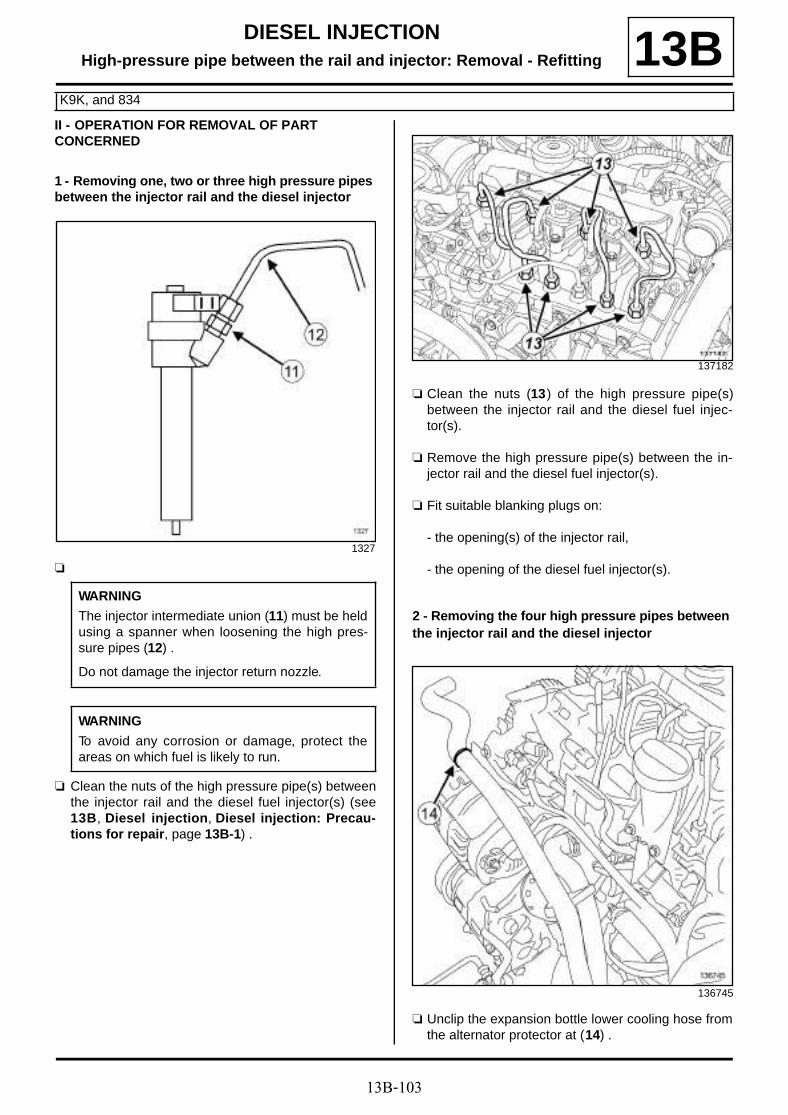
13B-103
DIESEL INJECTIONHigh-pressure pipe between the rail and injector: Removal - Refitting
K9K, and 834
13BII - OPERATION FOR REMOVAL OF PART CONCERNED
1 - Removing one, two or three high pressure pipes between the injector rail and the diesel injector
a
a Clean the nuts of the high pressure pipe(s) betweenthe injector rail and the diesel fuel injector(s) (see13B, Diesel injection, Diesel injection: Precau-tions for repair, page 13B-1) .
a Clean the nuts (13) of the high pressure pipe(s)between the injector rail and the diesel fuel injec-tor(s).
a Remove the high pressure pipe(s) between the in-jector rail and the diesel fuel injector(s).
a Fit suitable blanking plugs on:
- the opening(s) of the injector rail,
- the opening of the diesel fuel injector(s).
2 - Removing the four high pressure pipes between the injector rail and the diesel injector
a Unclip the expansion bottle lower cooling hose fromthe alternator protector at (14) .
1327
WARNING
The injector intermediate union (11) must be heldusing a spanner when loosening the high pres-sure pipes (12) .
Do not damage the injector return nozzle.
WARNING
To avoid any corrosion or damage, protect theareas on which fuel is likely to run.
137182
136745
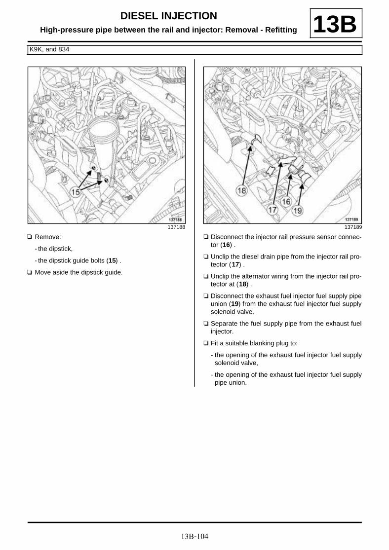
13B-104
DIESEL INJECTIONHigh-pressure pipe between the rail and injector: Removal - Refitting
K9K, and 834
13B
a Remove:
- the dipstick,
- the dipstick guide bolts (15) .
a Move aside the dipstick guide.
a Disconnect the injector rail pressure sensor connec-tor (16) .
a Unclip the diesel drain pipe from the injector rail pro-tector (17) .
a Unclip the alternator wiring from the injector rail pro-tector at (18) .
a Disconnect the exhaust fuel injector fuel supply pipeunion (19) from the exhaust fuel injector fuel supplysolenoid valve.
a Separate the fuel supply pipe from the exhaust fuelinjector.
a Fit a suitable blanking plug to:
- the opening of the exhaust fuel injector fuel supplysolenoid valve,
- the opening of the exhaust fuel injector fuel supplypipe union.
137188 137189

13B-105
DIESEL INJECTIONHigh-pressure pipe between the rail and injector: Removal - Refitting
K9K, and 834
13B
a Disconnect:
- the connector (20) for each diesel injector,
- the connector (21) for each heater plug.
a Unclip the diesel injection wiring from the injector railprotector at (22) .
a Remove the nut (23) for the diesel injection wiringfrom the lifting eye on the gearbox side.
a Move the diesel injection wiring aside.
a Remove:
- the nuts (24) from the injector rail protector,
- the injector rail protector.
a Undo the nuts (25) for the high pressure pipesbetween the injector rail and the diesel fuel injectors.
a Remove the high pressure pipes between the injec-tor rail and the diesel fuel injectors.
a Fit suitable blanking plugs on:
- the injector rail openings,
- the opening of the diesel fuel injectors.
137190
136740
137182

13B-106
DIESEL INJECTIONHigh-pressure pipe between the rail and injector: Removal - Refitting
K9K, and 834
13BREFITTING
I - REFITTING PREPARATION OPERATION
a
a parts always to be replaced: High-pressure pipebetween the rail and injector (11,05,03,01).
a parts always to be replaced: turbocharger aircooler air outlet pipe seal (10,09,04,05).
a Always replace the seal for the turbocharger air out-let pipe.
a Refit:
- a seal to the air outlet pipe of the new intercoolerinside the intercooler air outlet pipe,
- a seal to the air outlet pipe of the new turbochargerinside the turbocharger air outlet pipe.
II - REFITTING OPERATION FOR PART CONCERNED
1 - Refitting the four high pressure pipes between the injector rail and the diesel fuel injector
a Refit the high pressure pipes between the injectorrail and the new diesel fuel injectors.
a Screw on the nuts for the high pressure pipesbetween the injector rail and the diesel injectors byhand, without tightening.
a Tighten to torque:
- the nuts on the high pressure pipes betweenthe injector rail and the injectors at the injectorrail end (28 N.m) using the tool (Mot. 1746),
- the nuts on the high pressure pipes betweenthe injector rail and the diesel injectors at thediesel injector end (28 N.m) using the tool (Mot.1566).
a Refit the injector rail protector.
a Torque tighten the injector rail protector nuts (21N.m).
a Fit the diesel injection wiring.
a Refit the nut for the diesel injection wiring onto the lif-ting eye on the gearbox side.
a Clip the diesel injection wiring onto the injector railprotector.
a Connect:
- all heater plug connectors,
- the connector for each diesel injector.
a Remove the blanking plugs from:
- the opening of the exhaust fuel injector fuel supplysolenoid valve,
- the opening of the exhaust fuel injector fuel supplypipe union.
a Fit the exhaust fuel injector fuel supply pipe.
a Connect the exhaust fuel injector fuel supply pipeunion to the exhaust fuel injector fuel supply sole-noid valve.
a Clip the alternator wiring onto the injector rail protec-tor.
a Clip the diesel drain pipe onto the injector rail protec-tor.
a Connect the injector rail pressure sensor connector.
a Fit the dipstick guide tube.
a Torque tighten the dipstick guide tube bolt (8N.m).
20960
WARNING
Before fitting a new high pressure pipe, lightlylubricate the nut threads with the oil from theapplicator provided in the new parts kit.
Be careful not to allow oil into the high pressurepipe.
Do not lubricate high pressure pipes suppliedwithout an applicator, as these high pressurepipes are self-lubricating.

13B-107
DIESEL INJECTIONHigh-pressure pipe between the rail and injector: Removal - Refitting
K9K, and 834
13Ba Refit the dipstick.
a Clip the expansion bottle lower cooling hose ontothe alternator protector.
2 - Refitting one, two or three high pressure pipes between the injector rail and the diesel injector
a Remove the blanking plugs from:
- the opening(s) of the injector rail,
- the opening of the diesel fuel injector(s).
a Refit the high pressure pipe(s) between the injectorrail and the new diesel fuel injector(s).
a Screw on the nuts for the high pressure pipe(s)between the injector rail and the diesel injector(s) byhand without tightening, starting on the injector railside.
a Using the tool (Mot. 1566), torque tighten the nutsfor the high pressure pipe(s) between the injec-tor rail and the diesel injector(s) (28 N.m).
III - FINAL OPERATION
a Refit:
- the injector rail protector,
- the bolts for the injector rail protector cover plate.
a Clip the injector rail protector cover into place.
a Clip on the wiring for the damper valve.
a Refit the clip for the intercooler air outlet pipe.
a Clip on the intercooler air outlet pipe.
a Clip the turbocharger pressure sensor cable ontothe intercooler air outlet pipe.
a Connect the turbocharger pressure sensor connec-tor.
a Refit:
- the retaining bracket for the intermediate air pipebetween the turbocharger and the intercooler,
- the bolt for the retaining bracket of the intermediateair pipe between the turbocharger and the intercoo-ler.
a Refit the clip for the turbocharger air outlet pipe.
a Clip the intermediate air pipe between the turbochar-ger and the intercooler onto the turbocharger air out-let pipe.
a Refit:
- the bolt for the intermediate air pipe between theturbocharger and the intercooler,
- the nut for the intermediate air pipe between theturbocharger and the intercooler,
- the engine cover.
a Connect the battery (see Battery : Removal - Refit-ting) (80A, Battery).

13B-108
DIESEL INJECTIONInjector rail: Removal - Refitting
F9Q
13B
REMOVAL
I - REMOVAL PREPARATION OPERATION
a Position the vehicle on a two-post lift (see Vehicle:Towing and lifting) (02A, Lifting equipment).
a Disconnect the battery (see Battery : Removal -Refitting) (80A, Battery).
a Remove:
- the engine cover,
- the injector rail protector (see 13B, Diesel injec-tion, Injector rail protector: Removal - Refitting,page 13B-70) ,
- the high pressure pipes between the rail and the in-jector (see 13B, Diesel injection, High-pressurepipe between the rail and injector: Removal -Refitting, page 13B-87) ,
- the high pressure pipe between the pump and therail (see 13B, Diesel injection, High-pressurepipe between the pump and rail: Removal - Re-fitting, page 13B-71) ,
- the engine undertray bolts,
- the engine undertray,
- the oil separator (see 11A, Top and front of engi-ne, Oil decanter: Removal - Refitting, page 11A-205) .
a Disconnect the heater plug connectors (1) .
a Unclip the heater plug wiring from the lower protec-tor of the injector rail.
Essential special tooling
Mot. 1566 Spanner for removing highpressure pipes.
Tightening torquesm
injector rail bolts 30 Nm
nuts on the high pres-sure pipes between therail and the injector atthe injector end
27 N.m
nut on the high pressurepipe between the pumpand the rail at the highpressure pump end
27 N.m
nut on the high pressurepipe between the pumpand the rail at the injec-tor rail end
37 N.m
nuts on the high pres-sure pipes between therail and the injector atthe injector rail end
37 N.m
IMPORTANT
To avoid all risk of damage to the systems, applythe safety and cleanliness instructions and opera-tion recommendations before carrying out anyrepair (see 13B, Diesel injection, Diesel injec-tion: Precautions for repair, page 13B-1) .
135530

13B-109
DIESEL INJECTIONInjector rail: Removal - Refitting
F9Q
13B
a Remove the bolts (2) from the diesel fuel temperatu-re sensor support.
II - OPERATION FOR REMOVAL OF PART CONCERNED
a Remove:
- the injector rail bolts (3) ,
- the injector rail,
- the injector rail lower protector,
- the injector rail seal.
REFITTING
I - REFITTING PREPARATION OPERATION
a parts always to be replaced: High-pressure pipebetween the pump and rail (11,05,03,02).
parts always to be replaced: High-pressure pipebetween the rail and injector (11,05,03,01).
a
135575
135528
20960
WARNING
Before fitting a new high pressure pipe, lightlylubricate the nut threads with the oil from theapplicator provided in the new parts kit.
Be careful not to allow oil into the high pressurepipe.
Do not lubricate high pressure pipes suppliedwithout an applicator, as these high pressurepipes are self-lubricating.
WARNINGDo not remove the blanking plugs from eachcomponent until the last moment.
Also, do not remove the components from theirpackaging until they are to be fitted to the vehi-cle.

13B-110
DIESEL INJECTIONInjector rail: Removal - Refitting
F9Q
13BII - REFITTING OPERATION FOR PART CONCERNED
a Refit:
- a new injector rail seal,
- the injector rail lower protector,
- the injector rail.
a Fit without tightening the injector rail bolts.
a Refit a high pressure pipe between the pump andthe new injector rail.
a Without tightening it, screw in the high pressure pipebetween the pump and the rail.
a Refit the high pressure pipes between the new injec-tor rail and the injector.
a Fit the high pressure pipes between the rail and theinjector, without tightening.
a Tighten to torque:
- the injector rail bolts (30 Nm),
- the nuts on the high pressure pipes betweenthe rail and the injector at the injector end (27N.m),
- the nut on the high pressure pipe between thepump and the rail at the high pressure pumpend (27 N.m) using the tool (Mot. 1566),
- the nut on the high pressure pipe between thepump and the rail at the injector rail end (37N.m) using the tool (Mot. 1566),
- the nuts on the high pressure pipes betweenthe rail and the injector at the injector rail end(37 N.m).
III - FINAL OPERATION
a Refit the bolts for the diesel fuel temperature sensorsupport.
a Clip the heater plug wiring onto the lower protectorof the injector rail.
a Connect the heater plug connectors.
a Refit:
- the oil separator (see 11A, Top and front of engi-ne, Oil decanter: Removal - Refitting, page 11A-205) ,
- the engine undertray,
- the injector rail protector (see 13B, Diesel injec-tion, Injector rail protector: Removal - Refitting,page 13B-70) ,
- the engine cover.
a Connect the battery (see Battery : Removal - Refit-ting) (80A, Battery).

13B-111
DIESEL INJECTIONInjector rail: Removal - Refitting
K9K, and 832
13B
REMOVAL
I - REMOVAL PREPARATION OPERATION
a Disconnect the battery (see Battery : Removal -Refitting) (80A, Battery).
a Remove:
- the engine cover,
- the turbocharger air outlet pipe (see 12B, Turbo-charging, Intercooler air inlet pipe: Removal -Refitting, page 12B-41) ,
- the high pressure pipe between the high pressurepump and the injector rail (see 13B, Diesel injec-tion, High-pressure pipe between the pump andrail: Removal - Refitting, page 13B-71) ,
- the high pressure pipe between the injector rail andthe diesel injectors (see 13B, Diesel injection,High-pressure pipe between the rail and injec-tor: Removal - Refitting, page 13B-87) .
II - OPERATION FOR REMOVAL OF PART CONCERNED
a Remove:
- the nuts (1) from the injector rail,
- the injector rail.
REFITTING
I - REFITTING PREPARATION OPERATION
a
II - REFITTING OPERATION FOR PART CONCERNED
a Refit the injector rail.
a Without tightening, fit the injector rail nuts.
III - FINAL OPERATION
a Refit:
- the high pressure pipe between the injector rail andthe diesel injectors (see 13B, Diesel injection,High-pressure pipe between the rail and injec-tor: Removal - Refitting, page 13B-87) ,
Essential equipment
diagnostic tool
IMPORTANT
To avoid all risk of damage to the systems, applythe safety and cleanliness instructions and opera-tion recommendations before carrying out anyrepair (see 13B, Diesel injection, Diesel injec-tion: Precautions for repair, page 13B-1) .
IMPORTANTWear leaktight gloves (Nitrile type) for this opera-tion.
135007
WARNING
Do not remove the blanking plugs from eachcomponent until the last moment.
Also, do not remove the components from theirpackaging until they are to be fitted to the vehi-cle.

13B-112
DIESEL INJECTIONInjector rail: Removal - Refitting
K9K, and 832
13B- the high pressure pipe between the high pressurepump and the injector rail (see 13B, Diesel injec-tion, High-pressure pipe between the pump andrail: Removal - Refitting, page 13B-71) ,
- the turbocharger air outlet pipe (see 12B, Turbo-charging, Intercooler air inlet pipe: Removal -Refitting, page 12B-41) ,
- the engine cover.
a Connect the battery (see Battery : Removal - Refit-ting) (80A, Battery).
a Check that there are no diesel leaks.
a Apply the after repair procedure using the diagnos-tic tool :
- connect the diagnostic tool,
- select "Injection computer",
- go to repair mode,
- display the "After repair procedure" for the selectedcomputer,
- select "Injector rail pressure sensor" in the section"List of components connected to this computer",
- carry out the operations described in the "After re-pair procedure" section.

13B-113
DIESEL INJECTIONInjector rail: Removal - Refitting
K9K, and 830
13B
REMOVAL
I - REMOVAL PREPARATION OPERATION
a Disconnect the battery (see Battery : Removal -Refitting) (80A, Battery).
a Remove:
- the engine cover,
- the turbocharger air outlet pipe (see 12B, Turbo-charging, Intercooler air inlet pipe: Removal -Refitting, page 12B-41) ,
- the high pressure pipe between the high pressurepump and the injector rail (see 13B, Diesel injec-tion, High-pressure pipe between the pump andrail: Removal - Refitting, page 13B-71) ,
- the high pressure pipe between the injector rail andthe diesel injectors (see 13B, Diesel injection,High-pressure pipe between the rail and injec-tor: Removal - Refitting, page 13B-87) .
II - OPERATION FOR REMOVAL OF PART CONCERNED
a Remove:
- the nuts (1) from the injector rail,
- the injector rail.
REFITTING
I - REFITTING PREPARATION OPERATION
a
II - REFITTING OPERATION FOR PART CONCERNED
a Refit the injector rail.
a Without tightening, fit the injector rail nuts.
III - FINAL OPERATION
a Refit:
- the high pressure pipe between the injector rail andthe diesel injectors (see 13B, Diesel injection,High-pressure pipe between the rail and injec-tor: Removal - Refitting, page 13B-87) ,
Essential equipment
diagnostic tool
IMPORTANT
To avoid all risk of damage to the systems, applythe safety and cleanliness instructions and opera-tion recommendations before carrying out anyrepair (see 13B, Diesel injection, Diesel injec-tion: Precautions for repair, page 13B-1) .
IMPORTANT
Wear leaktight gloves (Nitrile type) for this opera-tion.
135869
WARNING
Do not remove the blanking plugs from eachcomponent until the last moment.
Also, do not remove the components from theirpackaging until they are to be fitted to the vehi-cle.

13B-114
DIESEL INJECTIONInjector rail: Removal - Refitting
K9K, and 830
13B- the high pressure pipe between the high pressurepump and the injector rail (see 13B, Diesel injec-tion, High-pressure pipe between the pump andrail: Removal - Refitting, page 13B-71) ,
- the turbocharger air outlet pipe (see 12B, Turbo-charging, Intercooler air inlet pipe: Removal -Refitting, page 12B-41) ,
- the engine cover.
a Connect the battery (see Battery : Removal - Refit-ting) (80A, Battery).
a Check the high pressure circuit (see High pressurepipe: Checking) .
a Apply the after repair procedure using the diagnos-tic tool :
- connect the diagnostic tool,
- select "Injection computer",
- go to repair mode,
- display the "After repair procedure" for the selectedcomputer,
- select "Injector rail pressure sensor" in the section"List of components controlled by this computer",
- carry out the operations described in the "After re-pair procedure" section.
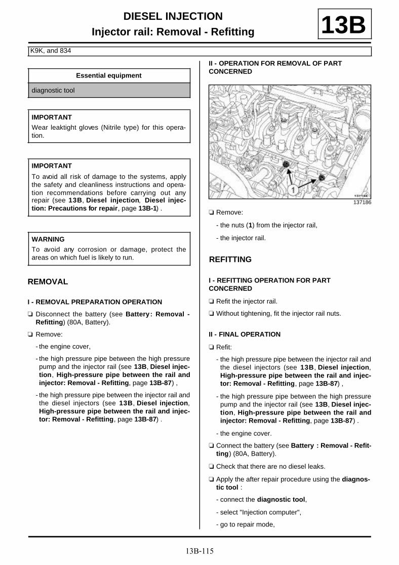
13B-115
DIESEL INJECTIONInjector rail: Removal - Refitting
K9K, and 834
13B
REMOVAL
I - REMOVAL PREPARATION OPERATION
a Disconnect the battery (see Battery : Removal -Refitting) (80A, Battery).
a Remove:
- the engine cover,
- the high pressure pipe between the high pressurepump and the injector rail (see 13B, Diesel injec-tion, High-pressure pipe between the rail andinjector: Removal - Refitting, page 13B-87) ,
- the high pressure pipe between the injector rail andthe diesel injectors (see 13B, Diesel injection,High-pressure pipe between the rail and injec-tor: Removal - Refitting, page 13B-87) .
II - OPERATION FOR REMOVAL OF PART CONCERNED
a Remove:
- the nuts (1) from the injector rail,
- the injector rail.
REFITTING
I - REFITTING OPERATION FOR PART CONCERNED
a Refit the injector rail.
a Without tightening, fit the injector rail nuts.
II - FINAL OPERATION
a Refit:
- the high pressure pipe between the injector rail andthe diesel injectors (see 13B, Diesel injection,High-pressure pipe between the rail and injec-tor: Removal - Refitting, page 13B-87) ,
- the high pressure pipe between the high pressurepump and the injector rail (see 13B, Diesel injec-tion, High-pressure pipe between the rail andinjector: Removal - Refitting, page 13B-87) .
- the engine cover.
a Connect the battery (see Battery : Removal - Refit-ting) (80A, Battery).
a Check that there are no diesel leaks.
a Apply the after repair procedure using the diagnos-tic tool :
- connect the diagnostic tool,
- select "Injection computer",
- go to repair mode,
Essential equipment
diagnostic tool
IMPORTANT
Wear leaktight gloves (Nitrile type) for this opera-tion.
IMPORTANT
To avoid all risk of damage to the systems, applythe safety and cleanliness instructions and opera-tion recommendations before carrying out anyrepair (see 13B, Diesel injection, Diesel injec-tion: Precautions for repair, page 13B-1) .
WARNING
To avoid any corrosion or damage, protect theareas on which fuel is likely to run.
137186

13B-116
DIESEL INJECTIONInjector rail: Removal - Refitting
K9K, and 834
13B- display the "After repair procedure" for the selectedcomputer,
- select "Injector rail pressure sensor" in the section"List of components controlled by this computer",
- carry out the operations described in the "After re-pair procedure" section.
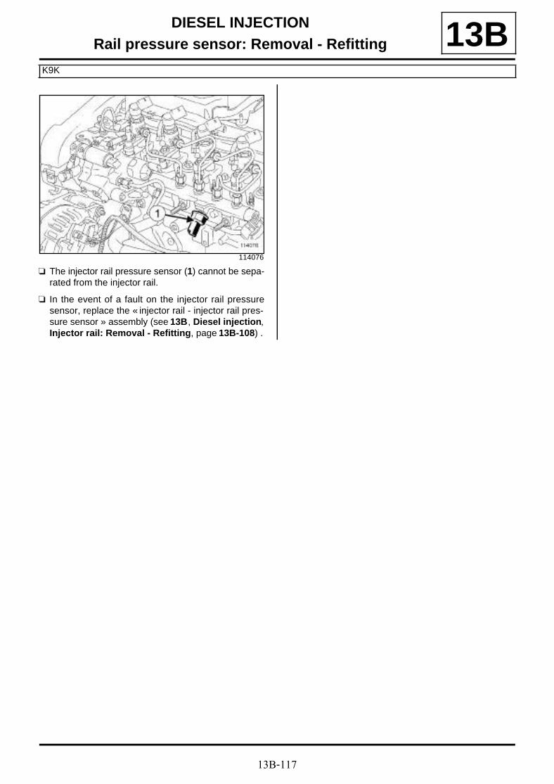
13B-117
DIESEL INJECTIONRail pressure sensor: Removal - Refitting
K9K
13B
a The injector rail pressure sensor (1) cannot be sepa-rated from the injector rail.
a In the event of a fault on the injector rail pressuresensor, replace the « injector rail - injector rail pres-sure sensor » assembly (see 13B, Diesel injection,Injector rail: Removal - Refitting, page 13B-108) .
114076

13B-118
DIESEL INJECTIONFuel temperature sensor: Removal - Refitting
K9K, and 832
13B
a The fuel temperature sensor (1) cannot be sapara-ted from the diesel injector fuel return rail.
a In the event of a fuel temperature sensor fault, repla-ce the « diesel injector fuel return rail - fuel tempera-ture sensor » assembly (see 13B, Diesel injection,Diesel injector fuel return rail: Removal - Refit-ting, page 13B-63) .
111747

13B-119
DIESEL INJECTIONFuel temperature sensor: Removal - Refitting
F9Q
13BREMOVAL
I - REMOVAL PREPARATION OPERATION
a Disconnect the battery (see Battery : Removal -Refitting) (80A, Battery).
a Remove the front engine cover.
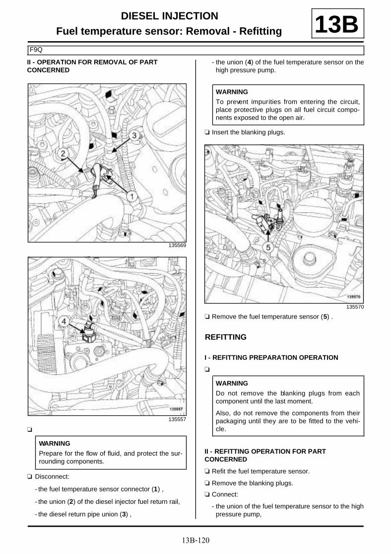
13B-120
DIESEL INJECTIONFuel temperature sensor: Removal - Refitting
F9Q
13BII - OPERATION FOR REMOVAL OF PART CONCERNED
a
a Disconnect:
- the fuel temperature sensor connector (1) ,
- the union (2) of the diesel injector fuel return rail,
- the diesel return pipe union (3) ,
- the union (4) of the fuel temperature sensor on thehigh pressure pump.
a Insert the blanking plugs.
a Remove the fuel temperature sensor (5) .
REFITTING
I - REFITTING PREPARATION OPERATION
a
II - REFITTING OPERATION FOR PART CONCERNED
a Refit the fuel temperature sensor.
a Remove the blanking plugs.
a Connect:
- the union of the fuel temperature sensor to the highpressure pump,
135569
135557
WARNING
Prepare for the flow of fluid, and protect the sur-rounding components.
WARNING
To prevent impurities from entering the circuit,place protective plugs on all fuel circuit compo-nents exposed to the open air.
135570
WARNING
Do not remove the blanking plugs from eachcomponent until the last moment.
Also, do not remove the components from theirpackaging until they are to be fitted to the vehi-cle.

13B-121
DIESEL INJECTIONFuel temperature sensor: Removal - Refitting
F9Q
13B- the diesel return pipe union,
- the union of the diesel injector fuel return rail,
- the fuel temperature sensor connector.
III - FINAL OPERATION
a Refit the engine cover.
a Connect the battery (see Battery : Removal - Refit-ting) (80A, Battery).

13B-122
DIESEL INJECTIONFuel temperature sensor: Removal - Refitting
K9K, and 834
13B
REMOVAL
I - REMOVAL PREPARATION OPERATION
a Remove the front engine cover.
II - OPERATION FOR REMOVAL OF PART CONCERNED
a Disconnect the fuel temperature sensor connector(1) .
Tightening torquesm
fuel temperature sensor 15 N.m
IMPORTANT
To avoid all risk of damage to the systems, applythe safety and cleanliness instructions and opera-tion recommendations before carrying out anyrepair (see 13B, Diesel injection, Diesel injec-tion: Precautions for repair, page 13B-1) .
IMPORTANTWear leaktight gloves (Nitrile type) for this opera-tion.
Note:
Ensure you have a new fuel temperature sensor tohand before opening up the fuel circuit.
137857
WARNING
To avoid any corrosion or damage, protect theareas on which fuel is likely to run.
WARNING
To prevent impurities from entering, once the fuelcircuit is opened, it must not be blasted with com-pressed air. Use cleaning cloths only, if neces-sary.
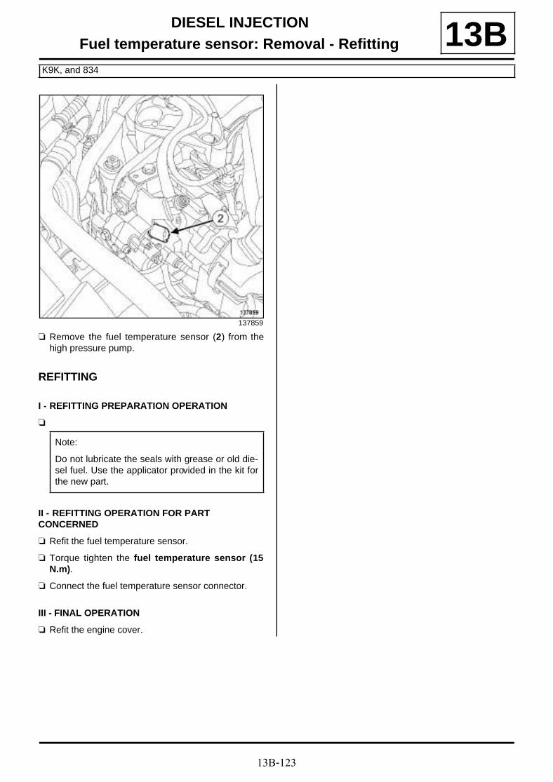
13B-123
DIESEL INJECTIONFuel temperature sensor: Removal - Refitting
K9K, and 834
13B
a Remove the fuel temperature sensor (2) from thehigh pressure pump.
REFITTING
I - REFITTING PREPARATION OPERATION
a
II - REFITTING OPERATION FOR PART CONCERNED
a Refit the fuel temperature sensor.
a Torque tighten the fuel temperature sensor (15N.m).
a Connect the fuel temperature sensor connector.
III - FINAL OPERATION
a Refit the engine cover.
137859
Note:
Do not lubricate the seals with grease or old die-sel fuel. Use the applicator provided in the kit forthe new part.

13B-124
DIESEL INJECTIONFuel temperature sensor: Removal - Refitting
K9K, and 830
13B
REMOVAL
I - REMOVAL PREPARATION OPERATION
a Remove the front engine cover.
a Disconnect the battery (see Battery : Removal -Refitting) (80A, Battery).
a Remove the turbocharger outlet air pipe (see 12B,Turbocharging, Intercooler air inlet pipe: Remo-val - Refitting, page 12B-41) .
a Unclip the injector rail protector cover at (1) .
a Remove:
- the injector rail protector cover bolt (2) ,
- the injection rail protector cover,
II - OPERATION FOR REMOVAL OF PART CONCERNED
a Disconnect the fuel temperature sensor connector(3) .
a Remove the fuel temperature sensor.
Tightening torquesm
fuel temperature sensor 15 N.m
IMPORTANT
To avoid all risk of damage to the systems, applythe safety and cleanliness instructions and opera-tion recommendations before carrying out anyrepair (see 13B, Diesel injection, Diesel injec-tion: Precautions for repair, page 13B-1) .
IMPORTANTWear leaktight gloves (Nitrile type) for this opera-tion.
WARNING
To avoid any corrosion or damage, protect theareas on which fuel is likely to run.
135878
135863

13B-125
DIESEL INJECTIONFuel temperature sensor: Removal - Refitting
K9K, and 830
13Ba Make sure that no impurities enter the high pressure
pump when the fuel temperature sensor is removed.
REFITTING
I - REFITTING OPERATION FOR PART CONCERNED
a Refit the fuel temperature sensor.
a Torque tighten the fuel temperature sensor (15N.m).
a Connect the fuel temperature sensor connector.
II - FINAL OPERATION
a Refit the injector rail protector cover.
a Clip on the injector rail protector cover.
a Refit the turbocharger air outlet pipe (see 12B, Tur-bocharging, Intercooler air inlet pipe: Removal -Refitting, page 12B-41) .
a Connect the battery (see Battery : Removal - Refit-ting) (80A, Battery).
a Start the engine.
a Check that there are no fuel leaks.
a Refit the engine cover.
WARNING
Do not blast with compressed air once the fuelcircuit is open, otherwise impurities may enterthe system. Only use cleaning cloths.

13B-126
DIESEL INJECTIONLeak flow from injectors: Check
K9K, and 832
13B
CHECKING
I - PREPARATION OPERATION FOR CHECK
a Remove the front engine cover.
a Disconnect the turbocharger pressure sensor con-nector (1) .
a Unclip the turbocharger pressure sensor wiring fromthe intercooler air outlet pipe at (2) .
a Loosen the clip (3) of the intercooler air outlet pipefrom the damper valve.
a Disconnect the intercooler outlet air pipe from thedamper valve.
a Move the intercooler outlet air pipe slightly awayfrom the damper valve.
Essential special tooling
Mot. 1771 Kit for measuring SIEMENSinjector leak rate.
Mot. 1711 Kit for measuring injector leakrate.
Essential equipment
self-contained starter
diagnostic tool
Tightening torquesm
intercooler air outletpipe clip on the dampervalve
5.5 N.m
intercooler air outletpipe clip on the dampervalve
5.5 N.m
IMPORTANT
To avoid all risk of damage to the systems, applythe safety and cleanliness instructions and opera-tion recommendations before carrying out anyrepair (see 13B, Diesel injection, Diesel injec-tion: Precautions for repair, page 13B-1) .
IMPORTANT
Wear leaktight gloves (Nitrile type) for this opera-tion.
134215
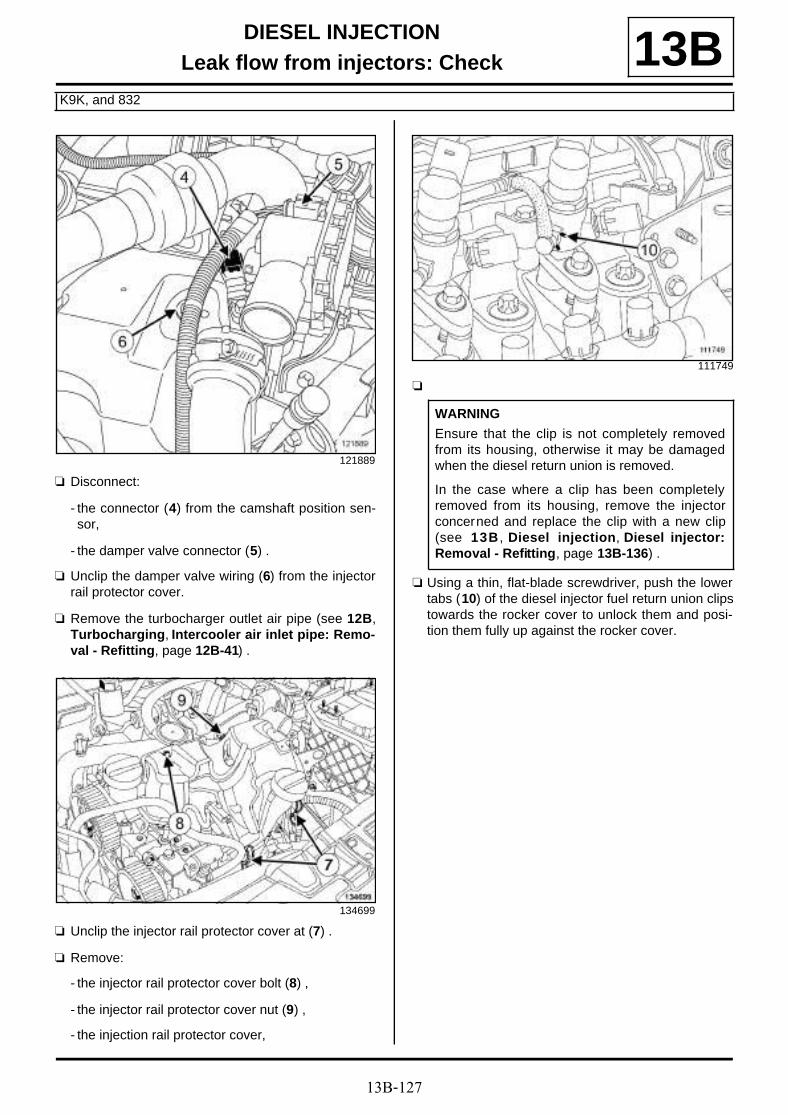
13B-127
DIESEL INJECTIONLeak flow from injectors: Check
K9K, and 832
13B
a Disconnect:
- the connector (4) from the camshaft position sen-sor,
- the damper valve connector (5) .
a Unclip the damper valve wiring (6) from the injectorrail protector cover.
a Remove the turbocharger outlet air pipe (see 12B,Turbocharging, Intercooler air inlet pipe: Remo-val - Refitting, page 12B-41) .
a Unclip the injector rail protector cover at (7) .
a Remove:
- the injector rail protector cover bolt (8) ,
- the injector rail protector cover nut (9) ,
- the injection rail protector cover,
a
a Using a thin, flat-blade screwdriver, push the lowertabs (10) of the diesel injector fuel return union clipstowards the rocker cover to unlock them and posi-tion them fully up against the rocker cover.
121889
134699
111749
WARNING
Ensure that the clip is not completely removedfrom its housing, otherwise it may be damagedwhen the diesel return union is removed.
In the case where a clip has been completelyremoved from its housing, remove the injectorconcerned and replace the clip with a new clip(see 13B , Diesel injection, Diesel injector:Removal - Refitting, page 13B-136) .

13B-128
DIESEL INJECTIONLeak flow from injectors: Check
K9K, and 832
13B
a
a Use a thin, flat-blade screwdriver to push down (11)on the lower tabs of the clips previously in contactwith the rocker cover, without fully removing the clipsfrom their injectors.
a Manually remove the diesel injector fuel return railunions (12) , while pressing (11) on the lower tabs ofthe clips using a thin, flat-blade screwdriver.
a Fit appropriate blanking plugs on each union of thediesel injector fuel return rail.
a Connect the four transparent hoses of the tool (Mot.1771) on the diesel injectors in place of each unionof the diesel injector fuel return rail.
a Insert these hoses in the four graduated measuringcylinders (13) of the tool (Mot. 1711).
a Connect:
- the camshaft position sensor connector,
- the connector to the damper flap.
a Fit the intercooler air outlet pipe.
a Connect the intercooler air outlet pipe on the dampervalve.
a Torque tighten the intercooler air outlet pipe clipon the damper valve (5.5 N.m).
a Refit the turbocharger air outlet pipe (see 12B, Tur-bocharging, Intercooler air inlet pipe: Removal -Refitting, page 12B-41) .
II - CHECKING OPERATION FOR PART CONCERNED
a Connect a self-contained starter.
a Force the vehicle's + after ignition feed.
a Connect the diagnostic tool.
a Run commands:
- RZ009 "Program vehicle functions",
- VP036 Inhibit fuel supply.
a Run the starter for 15 seconds.
a Check that the diesel injector return volume is grea-ter than or equal to 20 ml.
a Repeat the starting phase twice, allowing an intervalof 30 seconds between each starting phase.
a Run command VP037 Stop fuel supply inhibition.
120940
Note:
With sufficient force applied to the clip whilepressing continuously with the screwdriver, thediesel injector fuel return rail unions will come outeffortlessly.
WARNING
Do not use the screwdriver as a lever on theinjector fuel return unions.
107637

13B-129
DIESEL INJECTIONLeak flow from injectors: Check
K9K, and 832
13Ba Disconnect:
- the diagnostic tool,
- the self-contained starter.
III - FINAL OPERATION
a Remove the turbocharger outlet air pipe (see 12B,Turbocharging, Intercooler air inlet pipe: Remo-val - Refitting, page 12B-41) .
a Loosen the clip of the intercooler air outlet pipe fromthe damper valve.
a Disconnect:
- the intercooler air outlet pipe on the damper valve,
- the damper valve connector,
- the camshaft position sensor connector.
a Disconnect the four transparent pipes of the tool(Mot. 1771) from the diesel injectors.
a Push the diesel injector fuel return union clips to-wards the front of the vehicle to place them into theiroriginal positions.
a Remove the blanking plug from each diesel injectorfuel return rail opening.
a Lubricate the diesel injector fuel return unions withSILICONE-FREE LUBRICANT (see Vehicle:Parts and ingredients for the repairwork) (04B,Consumables - Products) until the seals are comple-tely covered.
a Place the diesel injector fuel return rail unions infront of the diesel injector openings starting with in-jector number 4 (timing end).
a Clip the diesel injector fuel return rail unions on thediesel injectors starting with injector number 4 (timi-ng end).
a Refit:
- the injector rail protector cover,
- the injector rail protector cover nut,
- the injector rail protector cover bolt.
a Clip on the injector rail protector cover.
a Fit the damper valve wiring.
a Clip the damper valve wiring onto the injector railprotector cover.
a Connect:
- the camshaft position sensor connector,
- the connector to the damper flap.
a Fit the intercooler air outlet pipe.
a Connect the intercooler air outlet pipe on the dampervalve.
a Clip the turbocharger pressure sensor wiring ontothe intercooler air outlet pipe.
a Connect the turbocharger pressure sensor connec-tor.
a Torque tighten the intercooler air outlet pipe clipon the damper valve (5.5 N.m).
a Refit:
- the turbocharger air outlet pipe (see 12B, Turbo-charging, Intercooler air inlet pipe: Removal -Refitting, page 12B-41) ,
- the engine cover.
WARNING
Check the condition of the seals on the fuelreturn unions on the injectors. Check that theyare not cut or crushed, and have not come out oftheir grooves. Replace the entire diesel returnpipe if one of the components is damaged
Note:
Check that the unions of the fuel return rail arecorrectly clipped.
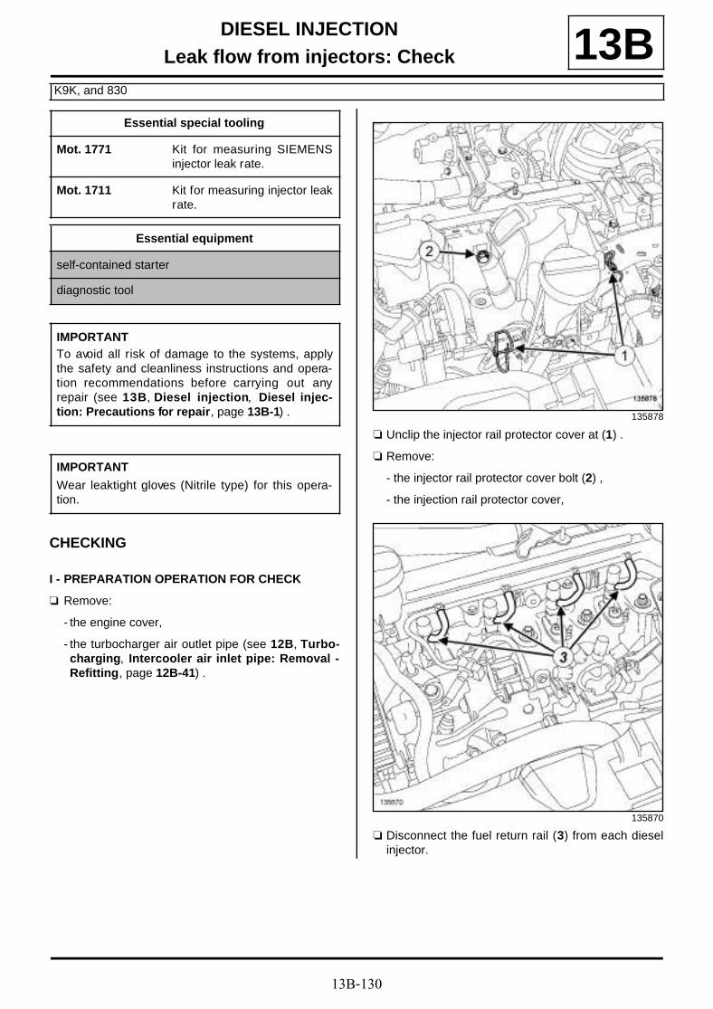
13B-130
DIESEL INJECTIONLeak flow from injectors: Check
K9K, and 830
13B
CHECKING
I - PREPARATION OPERATION FOR CHECK
a Remove:
- the engine cover,
- the turbocharger air outlet pipe (see 12B, Turbo-charging, Intercooler air inlet pipe: Removal -Refitting, page 12B-41) .
a Unclip the injector rail protector cover at (1) .
a Remove:
- the injector rail protector cover bolt (2) ,
- the injection rail protector cover,
a Disconnect the fuel return rail (3) from each dieselinjector.
Essential special tooling
Mot. 1771 Kit for measuring SIEMENSinjector leak rate.
Mot. 1711 Kit for measuring injector leakrate.
Essential equipment
self-contained starter
diagnostic tool
IMPORTANTTo avoid all risk of damage to the systems, applythe safety and cleanliness instructions and opera-tion recommendations before carrying out anyrepair (see 13B, Diesel injection, Diesel injec-tion: Precautions for repair, page 13B-1) .
IMPORTANT
Wear leaktight gloves (Nitrile type) for this opera-tion.
135878
135870

13B-131
DIESEL INJECTIONLeak flow from injectors: Check
K9K, and 830
13B
a Connect the four transparent hoses of the tool (Mot.1771) on the diesel injectors in place of each unionof the diesel injector fuel return rail.
a Insert these hoses in the four graduated measuringcylinders (6) of the tool (Mot. 1711).
a Refit the turbocharger air outlet pipe (see 12B, Tur-bocharging, Intercooler air inlet pipe: Removal -Refitting, page 12B-41) .
II - CHECKING OPERATION FOR PART CONCERNED
a Connect a self-contained starter.
a Force the vehicle's + after ignition feed.
a Connect the diagnostic tool.
a Run commands:
- RZ009 Vehicle function programming,
- VP036 Inhibit fuel supply.
a Run the starter for 15 seconds.
a Check that the injector return volume is greater thanor equal to 20 ml.
a Repeat the starting phase twice, allowing an intervalof 30 seconds between each starting phase.
a Run command VP037 Stop fuel supply inhibition.
a Disconnect:
- the diagnostic tool,
- the self-contained starter.
III - FINAL OPERATION
a Remove the turbocharger outlet air pipe (see 12B,Turbocharging, Intercooler air inlet pipe: Remo-val - Refitting, page 12B-41) .
a Disconnect the four transparent pipes of the tool(Mot. 1771) from the diesel injectors.
a Connect the diesel injector fuel return rail unions tothe diesel injectors.
a Refit:
- the injector rail protector cover,
- the injector rail protector cover bolt.
a Clip on the injector rail protector cover.
a Refit:
- the turbocharger air outlet pipe (see 12B, Turbo-charging, Intercooler air inlet pipe: Removal -Refitting, page 12B-41) ,
- the engine cover.
107637
Note:
Check that the unions of the fuel return rail arecorrectly connected.

13B-132
DIESEL INJECTIONLeak flow from injectors: Check
K9K, and 834
13B
CHECKING
I - PREPARATION OPERATION FOR CHECK
a Remove the front engine cover.
a Remove:
- the bolt (1) of the intermediate air pipe between theturbocharger and the intercooler,
- the nut (2) of the intermediate air pipe between theturbocharger and the intercooler.
a Pull the clip (3) of the turbocharger air outlet pipe.
a Move the intermediate air pipe between the turbo-charger and the intercooler away from the turbo-charger air outlet pipe.
a Remove:
- the bolt (4) of the retaining bracket of the interme-diate air pipe between the turbocharger and the in-tercooler,
- the retaining bracket of the intermediate air pipebetween the turbocharger and the intercooler.
Essential special tooling
Mot. 1771 Kit for measuring SIEMENSinjector leak rate.
Mot. 1711 Kit for measuring injector leakrate.
Essential equipment
self-contained starter
diagnostic tool
IMPORTANTTo avoid all risk of damage to the systems, applythe safety and cleanliness instructions and opera-tion recommendations before carrying out anyrepair (see 13B, Diesel injection, Diesel injec-tion: Precautions for repair, page 13B-1) .
IMPORTANT
Wear leaktight gloves (Nitrile type) for this opera-tion.
137183
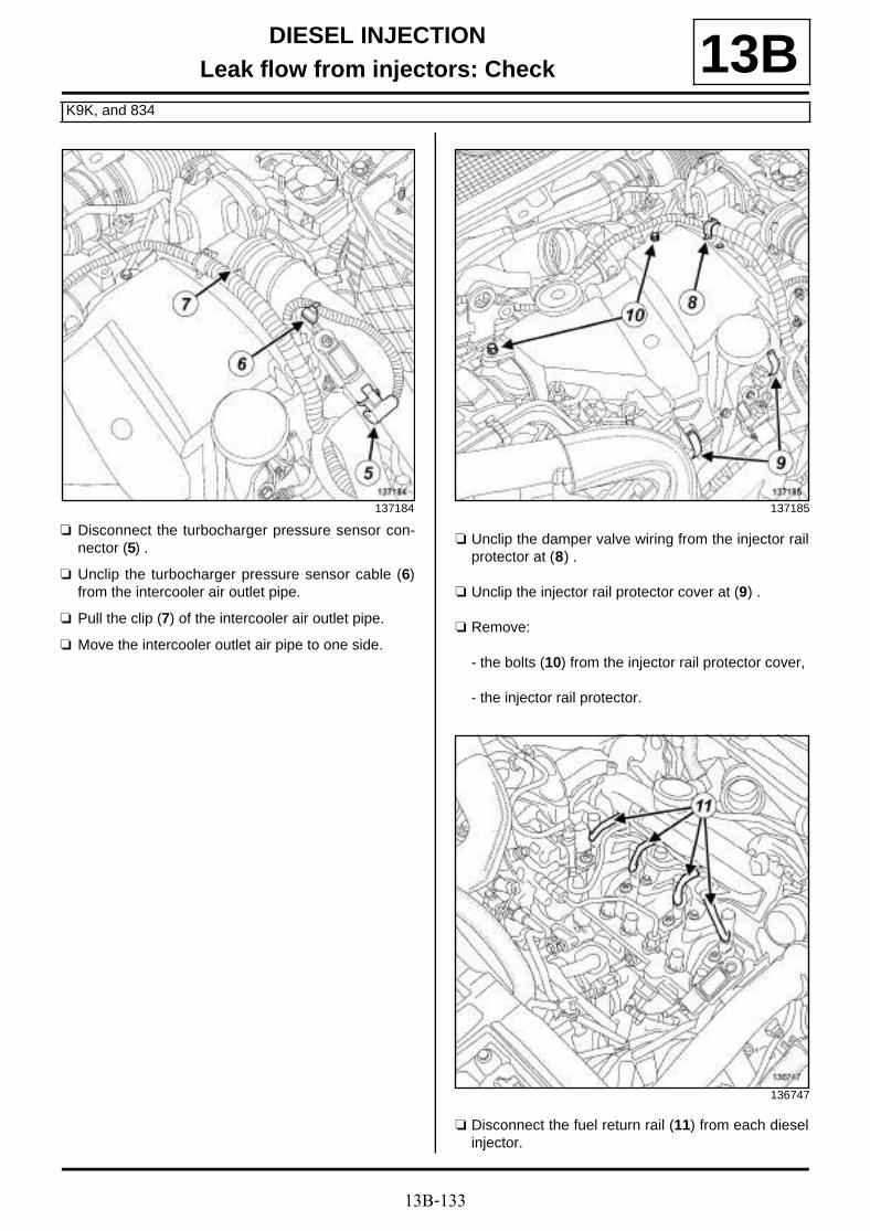
13B-133
DIESEL INJECTIONLeak flow from injectors: Check
K9K, and 834
13B
a Disconnect the turbocharger pressure sensor con-nector (5) .
a Unclip the turbocharger pressure sensor cable (6)from the intercooler air outlet pipe.
a Pull the clip (7) of the intercooler air outlet pipe.
a Move the intercooler outlet air pipe to one side.
a Unclip the damper valve wiring from the injector railprotector at (8) .
a Unclip the injector rail protector cover at (9) .
a Remove:
- the bolts (10) from the injector rail protector cover,
- the injector rail protector.
a Disconnect the fuel return rail (11) from each dieselinjector.
137184 137185
136747
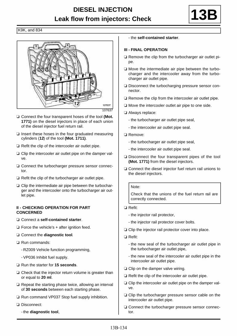
13B-134
DIESEL INJECTIONLeak flow from injectors: Check
K9K, and 834
13B
a Connect the four transparent hoses of the tool (Mot.1771) on the diesel injectors in place of each unionof the diesel injector fuel return rail.
a Insert these hoses in the four graduated measuringcylinders (12) of the tool (Mot. 1711).
a Refit the clip of the intercooler air outlet pipe.
a Clip the intercooler air outlet pipe on the damper val-ve.
a Connect the turbocharger pressure sensor connec-tor.
a Refit the clip of the turbocharger air outlet pipe.
a Clip the intermediate air pipe between the turbochar-ger and the intercooler onto the turbocharger air out-let pipe.
II - CHECKING OPERATION FOR PART CONCERNED
a Connect a self-contained starter.
a Force the vehicle's + after ignition feed.
a Connect the diagnostic tool.
a Run commands:
- RZ009 Vehicle function programming,
- VP036 Inhibit fuel supply.
a Run the starter for 15 seconds.
a Check that the injector return volume is greater thanor equal to 20 ml.
a Repeat the starting phase twice, allowing an intervalof 30 seconds between each starting phase.
a Run command VP037 Stop fuel supply inhibition.
a Disconnect:
- the diagnostic tool,
- the self-contained starter.
III - FINAL OPERATION
a Remove the clip from the turbocharger air outlet pi-pe.
a Move the intermediate air pipe between the turbo-charger and the intercooler away from the turbo-charger air outlet pipe.
a Disconnect the turbocharging pressure sensor con-nector.
a Remove the clip from the intercooler air outlet pipe.
a Move the intercooler outlet air pipe to one side.
a Always replace:
- the turbocharger air outlet pipe seal,
- the intercooler air outlet pipe seal.
a Remove:
- the turbocharger air outlet pipe seal,
- the intercooler air outlet pipe seal.
a Disconnect the four transparent pipes of the tool(Mot. 1771) from the diesel injectors.
a Connect the diesel injector fuel return rail unions tothe diesel injectors.
a Refit:
- the injector rail protector,
- the injector rail protector cover bolts.
a Clip the injector rail protector cover into place.
a Refit:
- the new seal of the turbocharger air outlet pipe inthe turbocharger air outlet pipe,
- the new seal of the intercooler air outlet pipe in theintercooler air outlet pipe.
a Clip on the damper valve wiring.
a Refit the clip of the intercooler air outlet pipe.
a Clip the intercooler air outlet pipe on the damper val-ve.
a Clip the turbocharger pressure sensor cable on theintercooler air outlet pipe.
a Connect the turbocharger pressure sensor connec-tor.
107637
Note:
Check that the unions of the fuel return rail arecorrectly connected.

13B-135
DIESEL INJECTIONLeak flow from injectors: Check
K9K, and 834
13Ba Refit:
- the retaining bracket of the intermediate air pipebetween the turbocharger and the intercooler,
- the bolt of the retaining bracket of the intermediateair pipe between the turbocharger and the intercoo-ler,
- the clip of the turbocharger air outlet pipe.
a Clip the intermediate air pipe between the turbochar-ger and the intercooler onto the turbocharger air out-let pipe.
a Refit:
- the bolt of the intermediate air pipe between theturbocharger and the intercooler,
- the nut of the intermediate air pipe between the tur-bocharger and the intercooler,
- the engine cover.

13B-136
DIESEL INJECTIONDiesel injector: Removal - Refitting
K9K, and 832
13B
REMOVAL
I - REMOVAL PREPARATION OPERATION
a Remove the front engine cover.
a Disconnect the battery (see Battery : Removal -Refitting) (80A, Battery).
a Remove:
- the diesel injector fuel return rail (see 13B, Dieselinjection, Diesel injector fuel return rail: Remo-val - Refitting, page 13B-63) ,
- the high pressure pipe(s) between the injector railand the diesel injector(s) (see 13B, Diesel injec-tion, High-pressure pipe between the rail andinjector: Removal - Refitting, page 13B-87) .
II - OPERATION FOR REMOVAL OF PART CONCERNED
a Remove:
- the bolt (1) from the bracket on the diesel injec-tor(s) concerned,
- the bracket of the diesel injector(s) concerned,
- the spacer of the diesel injector bracket concerned,
- the diesel injector(s) concerned,
- the compression washer located at the bottom ofthe diesel injector well concerned.
Essential equipment
compressed air nozzle
Tightening torquesm
bolt of the diesel injec-tor(s)
30 N.m
IMPORTANT
To avoid all risk of damage to the systems, applythe safety and cleanliness instructions and opera-tion recommendations before carrying out anyrepair (see 13B, Diesel injection, Diesel injec-tion: Precautions for repair, page 13B-1) .
IMPORTANT
Wear leaktight gloves (Nitrile type) for this opera-tion.
135008

13B-137
DIESEL INJECTIONDiesel injector: Removal - Refitting
K9K, and 832
13B
a
a Remove the diesel injector(s) from the well.
a Fit the appropriate blanking plug on the diesel injec-tor nose.
REFITTING
I - REFITTING PREPARATION OPERATION
a
a parts always to be replaced: injector seal (11,11,02,02).
Cleaning the injector well and the injector
a
a Soak the diesel injector in INJECTOR CLEANINGPRODUCT (see Vehicle: Parts and ingredientsfor the repairwork) (04B, Consumables - Pro-ducts).
a Clean the diesel injector nozzle:
- either using CLEANING CLOTHS (see Vehicle:Parts and ingredients for the repairwork) (04B,Consumables - Products) soaked in INJECTORCLEANING PRODUCT (see Vehicle: Parts andingredients for the repairwork) (04B, Consuma-bles - Products),
- or using a small brush with plastic bristles.
a Wipe using CLEANING RAGS (see Vehicle: Partsand ingredients for the repairwork) (04B, Consu-mables - Products).
114010
Note:
If a diesel injector is stuck in its well and does notcome out, turn the diesel injector at the flat sur-face of the diesel injector clamp using a 13 mmopen-ended spanner.
Note:
If reusing the diesel injector(s) keep them in ahermetically sealed bag throughout the removaloperation.
WARNING
Do not remove the blanking plugs from eachcomponent until the last moment.
Also, do not remove the components from theirpackaging until they are to be fitted to the vehi-cle.
WARNING
It is strictly forbidden to clean the injectors with:
- a wire brush,
- an emery cloth,
- an ultrasonic cleaner.
IMPORTANT
Wear leaktight gloves (Nitrile type) for this opera-tion.
WARNING
It is strictly forbidden to clean the injectors with:
- a wire brush,
- an emery cloth,
- an ultrasonic cleaner.
IMPORTANT
Wear leaktight gloves (Nitrile type) for this opera-tion.
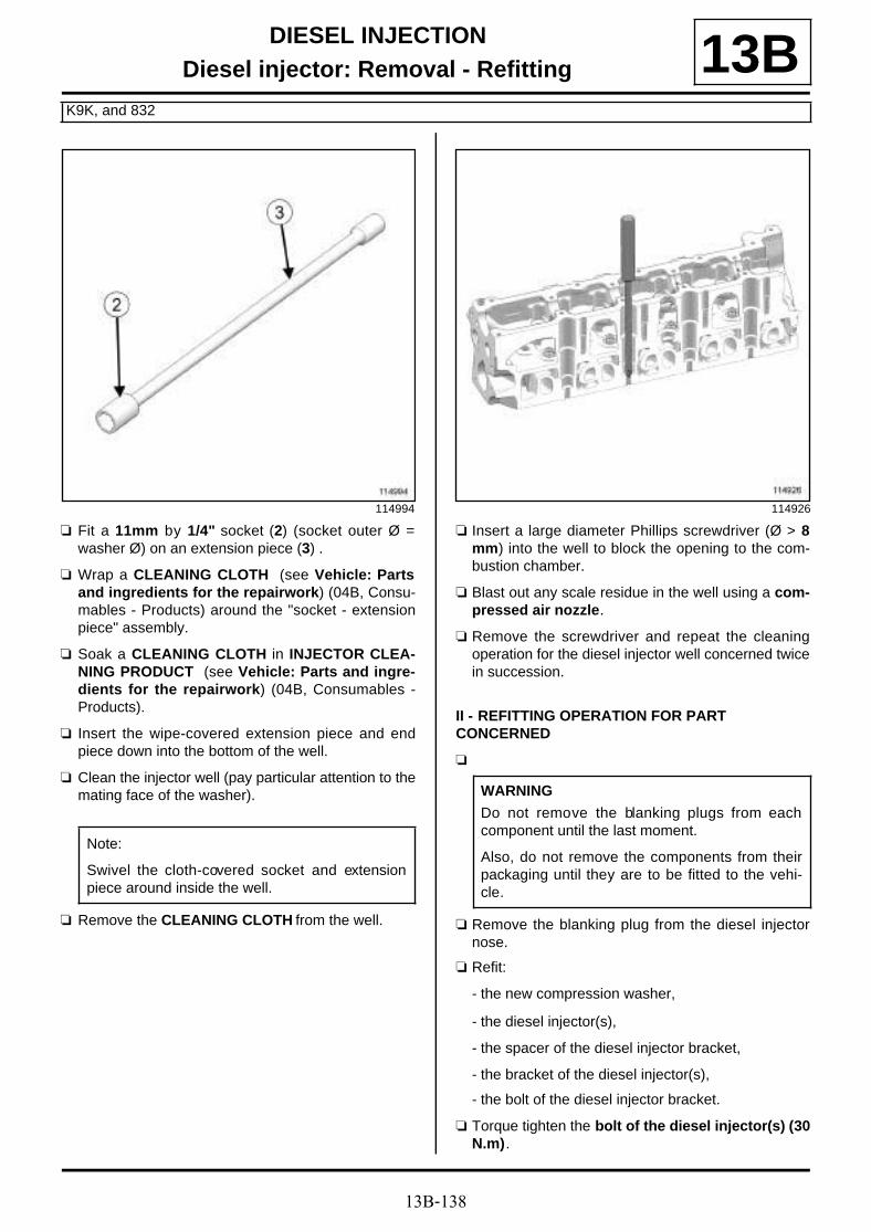
13B-138
DIESEL INJECTIONDiesel injector: Removal - Refitting
K9K, and 832
13B
a Fit a 11mm by 1/4" socket (2) (socket outer Ø =washer Ø) on an extension piece (3) .
a Wrap a CLEANING CLOTH (see Vehicle: Partsand ingredients for the repairwork) (04B, Consu-mables - Products) around the "socket - extensionpiece" assembly.
a Soak a CLEANING CLOTH in INJECTOR CLEA-NING PRODUCT (see Vehicle: Parts and ingre-dients for the repairwork) (04B, Consumables -Products).
a Insert the wipe-covered extension piece and endpiece down into the bottom of the well.
a Clean the injector well (pay particular attention to themating face of the washer).
a Remove the CLEANING CLOTH from the well.
a Insert a large diameter Phillips screwdriver (Ø > 8mm) into the well to block the opening to the com-bustion chamber.
a Blast out any scale residue in the well using a com-pressed air nozzle.
a Remove the screwdriver and repeat the cleaningoperation for the diesel injector well concerned twicein succession.
II - REFITTING OPERATION FOR PART CONCERNED
a
a Remove the blanking plug from the diesel injectornose.
a Refit:
- the new compression washer,
- the diesel injector(s),
- the spacer of the diesel injector bracket,
- the bracket of the diesel injector(s),
- the bolt of the diesel injector bracket.
a Torque tighten the bolt of the diesel injector(s) (30N.m).
114994
Note:
Swivel the cloth-covered socket and extensionpiece around inside the well.
114926
WARNING
Do not remove the blanking plugs from eachcomponent until the last moment.
Also, do not remove the components from theirpackaging until they are to be fitted to the vehi-cle.

13B-139
DIESEL INJECTIONDiesel injector: Removal - Refitting
K9K, and 832
13BIII - FINAL OPERATION
a Refit:
- the high pressure pipe(s) between the injector railand the diesel injector(s) (see 13B, Diesel injec-tion, High-pressure pipe between the rail andinjector: Removal - Refitting, page 13B-87) ,
- the diesel injector fuel return rail (see 13B, Dieselinjection, Diesel injector fuel return rail: Remo-val - Refitting, page 13B-63) .
a Connect the battery (see Battery : Removal - Refit-ting) (80A, Battery).
a Check that there are no diesel leaks.
a Refit the engine cover.

13B-140
DIESEL INJECTIONDiesel injector: Removal - Refitting
K9K, and 830
13B
REMOVAL
I - REMOVAL PREPARATION OPERATION
a Disconnect the battery (see Battery : Removal -Refitting) (80A, Battery).
a Remove:
- the engine cover,
- the high pressure pipe(s) between the injector railand the diesel injector(s) (see 13B, Diesel injec-tion, High-pressure pipe between the rail andinjector: Removal - Refitting, page 13B-87) .
a Clean the unions of the diesel injector return rail atthe diesel injectors (see 13B, Diesel injection, Die-sel injection: Precautions for repair, page 13B-1).
a Disconnect the diesel injector fuel return rail from thediesel injectors (1) .
a Fit an appropriate blanking plug on each diesel in-jector.
Essential equipment
open-ended spanner
compressed air nozzle
diagnostic tool
Tightening torquesm
bolts of the diesel injec-tor bracket
28 N.m
IMPORTANTTo avoid all risk of damage to the systems, applythe safety and cleanliness instructions and opera-tion recommendations before carrying out anyrepair (see 13B, Diesel injection, Diesel injec-tion: Precautions for repair, page 13B-1) .
IMPORTANT
Wear leaktight gloves (Nitrile type) for this opera-tion.
135870
WARNING
To avoid any corrosion or damage, protect theareas on which fuel is likely to run.
Note:
It is essential to fit an appropriate blanking plugto the Venturi to avoid depriming the fuel returncircuit.

13B-141
DIESEL INJECTIONDiesel injector: Removal - Refitting
K9K, and 830
13BII - OPERATION FOR REMOVAL OF PART CONCERNED
a
a Remove:
- the bolt (2) from the bracket on the diesel injec-tor(s) concerned,
- the diesel injector bracket,
- the compression washer located at the bottom ofthe diesel injector well concerned.
a Fit the appropriate blanking plug on the diesel injec-tor nose.
REFITTING
I - REFITTING PREPARATION OPERATION
a
a parts always to be replaced: injector seal (11,11,02,02).
Cleaning the diesel injector well
a
a Soak the diesel injector(s) in INJECTOR CLEA-NING PRODUCT (see Vehicle: Parts and ingre-dients for the repairwork) (04B, Consumables -Products).
a Clean the diesel injector nozzle:
- either using CLEANING CLOTHS (see Vehicle:Parts and ingredients for the repairwork) (04B,Consumables - Products) soaked in INJECTORCLEANING PRODUCT (see Vehicle: Parts andingredients for the repairwork) (04B, Consuma-bles - Products),
- or using a small brush with plastic bristles.
135868
Note:
If reusing one or more diesel injectors, it isessential to mark the injector in relation to itscylinder before removing it. If reusing the dieselinjector(s) keep them in a hermetically sealedbag throughout the removal operation.
Note:
If the diesel injector is stuck in the well and doesnot come out, turn the diesel injector at the flatsurface of the diesel injector bracket using anopen-ended spanner.
WARNING
Do not remove the blanking plugs from eachcomponent until the last moment.
Also, do not remove the components from theirpackaging until they are to be fitted to the vehi-cle.
WARNING
It is strictly forbidden to clean the injectors with:
- a wire brush,
- an emery cloth,
- an ultrasonic cleaner.
IMPORTANT
Wear leaktight gloves (Nitrile type) for this opera-tion.
WARNING
It is strictly forbidden to clean the injectors with:
- a wire brush,
- an emery cloth,
- an ultrasonic cleaner.

13B-142
DIESEL INJECTIONDiesel injector: Removal - Refitting
K9K, and 830
13Ba Wipe using CLEANING RAGS (see Vehicle: Parts
and ingredients for the repairwork) (04B, Consu-mables - Products).
a Fit an 11mm by 1/4" socket (3) (socket outer Ø =washer Ø) on an extension piece (4) .
a Wrap a CLEANING CLOTH (see Vehicle: Partsand ingredients for the repairwork) (04B, Consu-mables - Products) around the "socket - extensionpiece" assembly.
a Soak a CLEANING CLOTH in INJECTOR CLEA-NING PRODUCT (see Vehicle: Parts and ingre-dients for the repairwork) (04B, Consumables -Products).
a Insert the wipe-covered extension piece and endpiece down into the bottom of the well.
a Clean the diesel injector well (pay particular atten-tion to the mating face of the washer).
a Remove the CLEANING CLOTH from the well.
a Insert a large diameter Phillips screwdriver (Ø > 8mm) into the well to block the opening to the com-bustion chamber.
a Blast out any scale residue in the well using a com-pressed air nozzle.
a Remove the screwdriver and repeat the cleaningoperation for the injector well(s) concerned twice insuccession.
II - REFITTING OPERATION FOR PART CONCERNED
a
a Refit:
- a new compression washer,
- the diesel injector(s),
- the diesel injector bracket,
- the bolt of the diesel injector bracket.
IMPORTANT
Wear leaktight gloves (Nitrile type) for this opera-tion.
114994
Note:
Swivel the cloth covered socket and extensionpiece around inside the well.
114926
WARNING
Do not remove the blanking plugs from eachcomponent until the last moment.
Also, do not remove the components from theirpackaging until they are to be fitted to the vehi-cle.

13B-143
DIESEL INJECTIONDiesel injector: Removal - Refitting
K9K, and 830
13B
a
a Torque tighten the bolts of the diesel injectorbracket (28 N.m).
III - FINAL OPERATION
a Remove the blanking plug of each diesel injector.
a Refit the high pressure pipe(s) between the injectorrail and the diesel injector(s) (see 13B, Diesel injec-tion, High-pressure pipe between the rail and in-jector: Removal - Refitting, page 13B-87) .
a Connect the diesel injector fuel return rail to the die-sel injector.
a Check that there are no fuel leaks.
a Connect the battery (see Battery : Removal - Refit-ting) (80A, Battery).
a Refit the engine cover.
a Apply the after repair procedure using the diagnos-tic tool :
- connect the diagnostic tool,
- select "Injection computer",
- go to repair mode,
- display the "Before/after repair procedure" for thecomputer selected,
- select "Injector" in the "List of components storedby this computer" section,
- carry out the operations described in the "After re-pair procedure" section.
19724
Note:
If reusing a diesel injector, refit the injector in thecylinder marked beforehand. If reusing a dieselinjector, note the alphanumeric code (5) of theinjector and the cylinder on which it is fitted.

13B-144
DIESEL INJECTIONDiesel injector: Removal - Refitting
F9Q
13B
REMOVAL
I - REMOVAL PREPARATION OPERATION
a Disconnect the battery (see Battery : Removal -Refitting) (80A, Battery).
a Remove:
- the engine cover,
- the injector rail protector (see 13B, Diesel injec-tion, Injector rail protector: Removal - Refitting,page 13B-70) ,
- the diesel injector fuel return rail (see 13B, Dieselinjection, Diesel injector fuel return rail: Remo-val - Refitting, page 13B-63) ,
- the high pressure pipes between the rail and the in-jector (see 13B, Diesel injection, High-pressurepipe between the rail and injector: Removal -Refitting, page 13B-87) .
II - OPERATION FOR REMOVAL OF PART CONCERNED
a If one or more injectors are re-used, always mark aremoved injector in relation to its cylinder.
a Disconnect the injector connector (5) .
Essential special tooling
Mot. 1817 Injector well cleaning kit
Essential equipment
diagnostic tool
Tightening torquesm
diesel injector bracketbolt
25 N.m
IMPORTANT
To avoid all risk of damage to the systems, applythe safety and cleanliness instructions and opera-tion recommendations before carrying out anyrepair (see 13B, Diesel injection, Diesel injec-tion: Precautions for repair, page 13B-1) .
IMPORTANT
Wear leaktight gloves (Nitrile type) for this opera-tion.
WARNING
To avoid any corrosion or damage, protect theareas on which fuel is likely to run.
Note:
an injector corresponds to a cylinder.
135527

13B-145
DIESEL INJECTIONDiesel injector: Removal - Refitting
F9Q
13B
a Remove:
- the injector clamp bolt (2) ,
- the injector (3) and its clamp (4) ,
- the heat protection washer (5) .
a Fit an appropriate blanking plug on the diesel injec-tor nose.
REFITTING
I - REFITTING PREPARATION OPERATION
a parts always to be replaced: injector seal (11,11,02,02).
a Always clean the well of the removed injector (seeInjector well cleaning tool: Use) (Technical Note6040, 13B, Diesel injection).
a If reusing the removed injector:
- clean the injector using a wipe soaked in injectorcleaning product or brake cleaner,
- if necessary, leave the injector nozzle to soak in in-jector cleaner,
- wipe the injector with a new wipe,
- (see Vehicle: Parts and ingredients for the re-pairwork) (04B, Consumables - Products) and(see 13B, Diesel injection, Diesel injection: Pre-cautions for repair, page 13B-1) .
II - REFITTING OPERATION FOR PART CONCERNED
a
a Refit:
- a new compression washer,
- the diesel injector with its bracket.
a Torque tighten the diesel injector bracket bolt (25N.m).
a Connect the injector connector.
III - FINAL OPERATION
a Refit:
- the high pressure pipes between the rail and the in-jector (see 13B, Diesel injection, High-pressurepipe between the rail and injector: Removal -Refitting, page 13B-87) ,
1326
Note:
If reusing the diesel injector(s) keep them in ahermetically sealed bag throughout the removaloperation.
Note:
If the compression washer is stuck at the bottomof the well, use the tool (Mot. 1817) (see Injec-tor well cleaning tool: Use) (Technical Note6040, 13B, Diesel injection).
WARNING
It is strictly forbidden to clean the injectors with:
- a wire brush,
- an emery cloth,
- an ultrasonic cleaner.
WARNING
Do not remove the blanking plugs from eachcomponent until the last moment.
Also, do not remove the components from theirpackaging until they are to be fitted to the vehi-cle.

13B-146
DIESEL INJECTIONDiesel injector: Removal - Refitting
F9Q
13B- the diesel injector fuel return rail (see 13B, Dieselinjection, Diesel injector fuel return rail: Remo-val - Refitting, page 13B-63) ,
- the injector rail protector (see 13B, Diesel injec-tion, Injector rail protector: Removal - Refitting,page 13B-70) ,
- the engine cover.
a Connect the battery (see Battery : Removal - Refit-ting) (80A, Battery).
a Apply the after repair procedure using the diagnos-tic tool :
- connect the diagnostic tool,
- select « Injection computer » ,
- go to repair mode,
- display the « before/after repair procedure » for thecomputer selected,
- select « Injector » in the « List of components sto-red by this computer » section,
- carry out the operations described in the « After re-pair procedure » section.
a Check that there are no fuel leaks.

13B-147
DIESEL INJECTIONDiesel injector: Removal - Refitting
K9K, and 834
13B
REMOVAL
I - REMOVAL PREPARATION OPERATION
a Remove the front engine cover.
a Disconnect the battery (see Battery : Removal -Refitting) (80A, Battery).
a Remove the high pressure pipe(s) between the in-jector rail and the diesel injector(s) (see 13B, Dieselinjection, High-pressure pipe between the railand injector: Removal - Refitting, page 13B-87) .
a Clean the unions of the diesel injector return rail onthe diesel injectors (see 13B, Diesel injection, Die-sel injection: Precautions for repair, page 13B-1).
a Disconnect the diesel injector fuel return rail from thediesel injector(s) at (1) .
II - OPERATION FOR REMOVAL OF PART CONCERNED
a Remove:
- the bolt (2) from the bracket on the diesel injec-tor(s) concerned,
Essential equipment
compressed air nozzle
diagnostic tool
Tightening torquesm
bolt of the diesel injectorbracket
27 N.m
IMPORTANT
To avoid all risk of damage to the systems, applythe safety and cleanliness instructions and opera-tion recommendations before carrying out anyrepair (see 13B, Diesel injection, Diesel injec-tion: Precautions for repair, page 13B-1) .
IMPORTANT
Wear leaktight gloves (Nitrile type) for this opera-tion.
WARNING
To avoid any corrosion or damage, protect theareas on which fuel is likely to run.
136747
136748
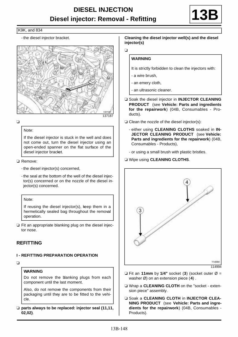
13B-148
DIESEL INJECTIONDiesel injector: Removal - Refitting
K9K, and 834
13B- the diesel injector bracket.
a
a Remove:
- the diesel injector(s) concerned,
- the seal at the bottom of the well of the diesel injec-tor(s) concerned or on the nozzle of the diesel in-jector(s) concerned.
a Fit an appropriate blanking plug on the diesel injec-tor nose.
REFITTING
I - REFITTING PREPARATION OPERATION
a
a parts always to be replaced: injector seal (11,11,02,02).
Cleaning the diesel injector well(s) and the diesel injector(s)
a
a Soak the diesel injector in INJECTOR CLEANINGPRODUCT (see Vehicle: Parts and ingredientsfor the repairwork) (04B, Consumables - Pro-ducts).
a Clean the nozzle of the diesel injector(s):
- either using CLEANING CLOTHS soaked in IN-JECTOR CLEANING PRODUCT (see Vehicle:Parts and ingredients for the repairwork) (04B,Consumables - Products),
- or using a small brush with plastic bristles.
a Wipe using CLEANING CLOTHS.
a Fit an 11mm by 1/4" socket (3) (socket outer Ø =washer Ø) on an extension piece (4) .
a Wrap a CLEANING CLOTH on the "socket - exten-sion piece" assembly.
a Soak a CLEANING CLOTH in INJECTOR CLEA-NING PRODUCT (see Vehicle: Parts and ingre-dients for the repairwork) (04B, Consumables -Products).
137187
Note:
If the diesel injector is stuck in the well and doesnot come out, turn the diesel injector using anopen-ended spanner on the flat surface of thediesel injector bracket.
Note:
If reusing the diesel injector(s), keep them in ahermetically sealed bag throughout the removaloperation.
WARNING
Do not remove the blanking plugs from eachcomponent until the last moment.
Also, do not remove the components from theirpackaging until they are to be fitted to the vehi-cle.
WARNING
It is strictly forbidden to clean the injectors with:
- a wire brush,
- an emery cloth,
- an ultrasonic cleaner.
114994

13B-149
DIESEL INJECTIONDiesel injector: Removal - Refitting
K9K, and 834
13Ba Insert the wipe-covered extension piece and end
piece down into the bottom of the well.
a Clean the injector well (pay particular attention to themating face of the washer).
a Remove the CLEANING CLOTH from the well.
a Insert a large diameter Phillips screwdriver (Ø > 8mm) into the well to block the opening to the com-bustion chamber.
a Blast out any scale residue in the well using a com-pressed air nozzle.
a Remove the screwdriver and repeat the cleaningoperation for the injector well concerned twice insuccession.
II - REFITTING OPERATION FOR PART CONCERNED
a Remove the blanking plug from the nozzle of the die-sel injector(s).
a Refit:
- a seal on the new diesel injector(s),
- the diesel injector(s),
- the diesel injector bracket.
a Torque tighten the bolt of the diesel injector brac-ket (27 N.m).
III - FINAL OPERATION
a Connect the diesel injector fuel return rail to the die-sel injector(s).
a Refit the high pressure pipe(s) between the injectorrail and the diesel injector(s) (see 13B, Diesel injec-tion, High-pressure pipe between the rail and in-jector: Removal - Refitting, page 13B-87) .
a Connect the battery (see Battery : Removal - Refit-ting) (80A, Battery).
a Check that there are no diesel leaks.
a Refit the engine cover.
a Apply the after repair procedure using the diagnos-tic tool :
- connect the diagnostic tool,
- select "Injection computer",
- go to repair mode,
- display the "Before/after repair procedure" for thecomputer selected,
- select "Injector" in the "List of components storedby this computer" section,
- carry out the operations described in the "After re-pair procedure" section.
Note:
Swivel the cloth covered socket and extensionpiece around inside the well.
114926
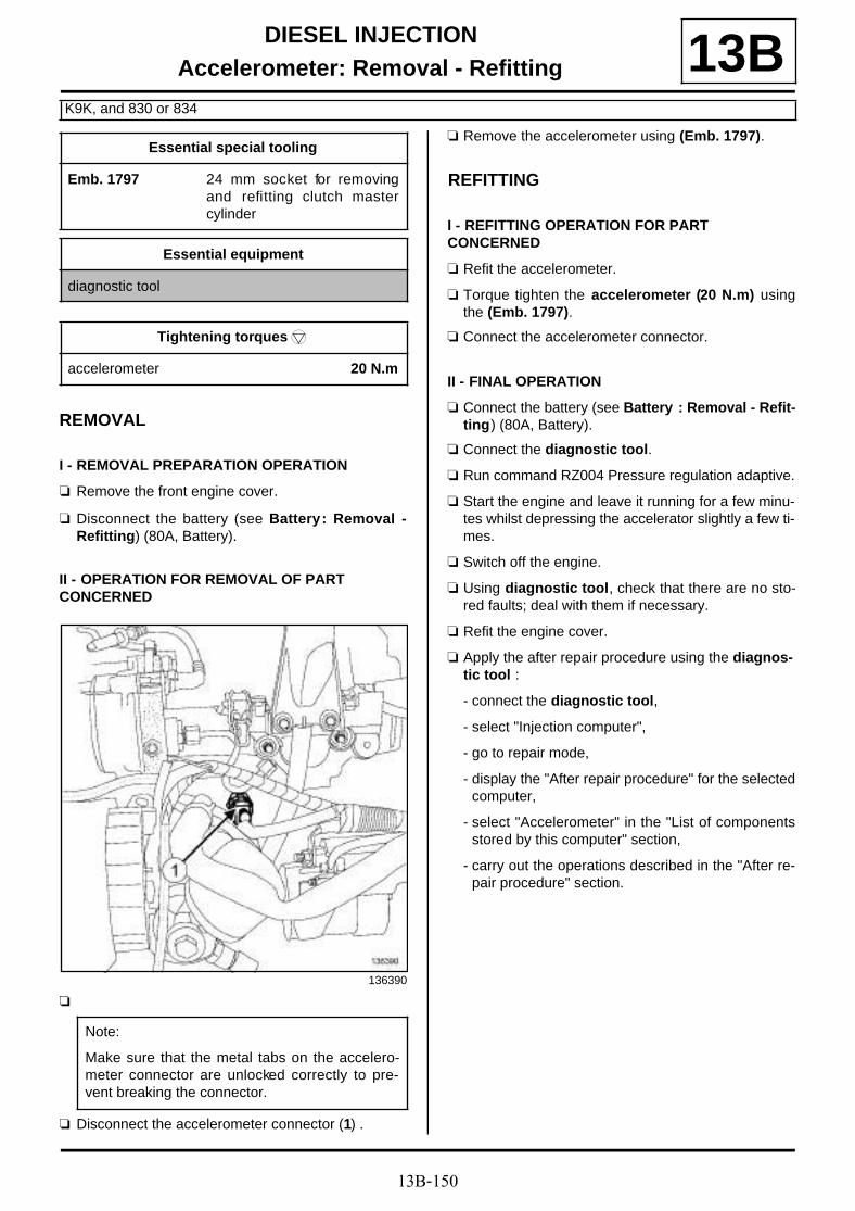
13B-150
DIESEL INJECTIONAccelerometer: Removal - Refitting
K9K, and 830 or 834
13B
REMOVAL
I - REMOVAL PREPARATION OPERATION
a Remove the front engine cover.
a Disconnect the battery (see Battery : Removal -Refitting) (80A, Battery).
II - OPERATION FOR REMOVAL OF PART CONCERNED
a
a Disconnect the accelerometer connector (1) .
a Remove the accelerometer using (Emb. 1797).
REFITTING
I - REFITTING OPERATION FOR PART CONCERNED
a Refit the accelerometer.
a Torque tighten the accelerometer (20 N.m) usingthe (Emb. 1797).
a Connect the accelerometer connector.
II - FINAL OPERATION
a Connect the battery (see Battery : Removal - Refit-ting) (80A, Battery).
a Connect the diagnostic tool.
a Run command RZ004 Pressure regulation adaptive.
a Start the engine and leave it running for a few minu-tes whilst depressing the accelerator slightly a few ti-mes.
a Switch off the engine.
a Using diagnostic tool, check that there are no sto-red faults; deal with them if necessary.
a Refit the engine cover.
a Apply the after repair procedure using the diagnos-tic tool :
- connect the diagnostic tool,
- select "Injection computer",
- go to repair mode,
- display the "After repair procedure" for the selectedcomputer,
- select "Accelerometer" in the "List of componentsstored by this computer" section,
- carry out the operations described in the "After re-pair procedure" section.
Essential special tooling
Emb. 1797 24 mm socket for removingand refitting clutch mastercylinder
Essential equipment
diagnostic tool
Tightening torquesm
accelerometer 20 N.m
136390
Note:
Make sure that the metal tabs on the accelero-meter connector are unlocked correctly to pre-vent breaking the connector.

13C-1
PREHEATINGPre/postheating unit: Removal - Refitting
F9Q or K9K
13CREMOVAL
I - OPERATION FOR REMOVAL OF PART CONCERNED
a Position the vehicle on a two-post lift (see Vehicle:Towing and lifting) (02A, Lifting equipment).
a Disconnect the battery (see Battery : Removal -Refitting) (80A, Battery).
a Remove:
- the front wheels (see Wheel: Removal - Refitting)(35A, Wheels and tyres),
- the front section of the front wheel arch liners (seeFront wheel arch liner: Removal - Refitting)(55A, Exterior protection),
- the front bumper (see Front bumper: Removal -Refitting) (55A, Exterior protection),
- the air resonator (see 12A, Fuel mixture, Air reso-nator: Removal - Refitting, page 12A-1) .
a Remove the air resonator support nuts (1) .
a Move aside the air resonator support.
II - OPERATION FOR REMOVAL OF PART CONCERNED
a Disconnect the pre-postheating unit connector (2) .
a Remove:
- the pre-postheating unit nut (3) ,
- the pre/postheating unit.
F9Q or K9K, and 830
136669
K9K
135505
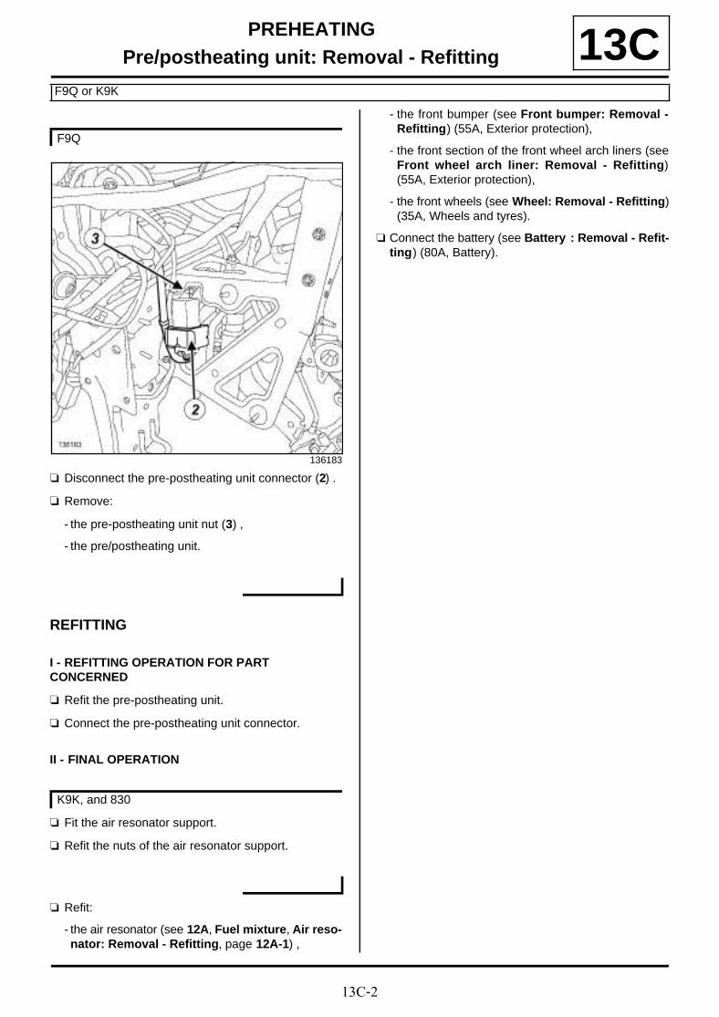
13C-2
PREHEATINGPre/postheating unit: Removal - Refitting
F9Q or K9K
13C
a Disconnect the pre-postheating unit connector (2) .
a Remove:
- the pre-postheating unit nut (3) ,
- the pre/postheating unit.
REFITTING
I - REFITTING OPERATION FOR PART CONCERNED
a Refit the pre-postheating unit.
a Connect the pre-postheating unit connector.
II - FINAL OPERATION
a Fit the air resonator support.
a Refit the nuts of the air resonator support.
a Refit:
- the air resonator (see 12A, Fuel mixture, Air reso-nator: Removal - Refitting, page 12A-1) ,
- the front bumper (see Front bumper: Removal -Refitting) (55A, Exterior protection),
- the front section of the front wheel arch liners (seeFront wheel arch liner: Removal - Refitting)(55A, Exterior protection),
- the front wheels (see Wheel: Removal - Refitting)(35A, Wheels and tyres).
a Connect the battery (see Battery : Removal - Refit-ting) (80A, Battery).
F9Q
136183
K9K, and 830

13C-3
PREHEATINGHeater plugs Removal - Refitting
F9Q
13C
REMOVAL
I - REMOVAL PREPARATION OPERATION
a Disconnect the battery (see Battery : Removal -Refitting) (80A, Battery).
a Remove:
- the engine cover,
- the injector rail protector (see 13B, Diesel injec-tion, Injector rail protector: Removal - Refitting,page 13B-70) .
II - OPERATION FOR REMOVAL OF PART CONCERNED
a Disconnect the heater plug connectors (1) .
a Clean around the outside of the heater plugs with acompressed air gun to prevent any impurities fromentering the cylinders.
a Unscrew the heater plugs using a 10 mm long soc-ket connected to a universal joint or a hingedwrench for heater plug.
REMOVAL
I - REFITTING PREPARATION OPERATION
a
Essential equipment
tool for removing heater plugs
hinged wrench for heater plug
Tightening torquesm
heater plugs 15 N.m
135530
IMPORTANT
Wear goggles with side protectors for this opera-tion.
Note:
If the heater plugs are seized, use the tool forremoving heater plugs (see Heater plug remo-val tool: Use) (Technical Note 5197A, 06A, Too-ling).
WARNING
Ensure that no dirt enters the cylinder during thisoperation.
13C-4
PREHEATINGHeater plugs Removal - Refitting
F9Q
13CII - REFITTING OPERATION FOR PART CONCERNED
a Refit the heater plugs
a Tighten to torque the heater plugs (15 N.m) using a10 mm long socket.
a Connect the heater plug connectors.
III - FINAL OPERATION
a Refit:
- the injector rail protector (see 13B, Diesel injec-tion, Injector rail protector: Removal - Refitting,page 13B-70) ,
- the engine cover.
a Connect the battery (see Battery : Removal - Refit-ting) (80A, Battery).

13C-5
PREHEATINGHeater plugs Removal - Refitting
K9K, and 832
13C
REMOVAL
I - REMOVAL PREPARATION OPERATION
a Remove:
- the engine cover,
- the turbocharger air outlet pipe (see 12B, Turbo-charging, Intercooler air inlet pipe: Removal -Refitting, page 12B-41) .
a Loosen the clip (1) of the intercooler air outlet pipefrom the damper valve.
a Disconnect the intercooler outlet air pipe from thedamper valve.
a Move the intercooler outlet air pipe slightly awayfrom the damper valve.
a Disconnect:
- the connector (2) from the camshaft position sen-sor,
- the damper valve connector (3) .
a Unclip the camshaft position sensor wiring and thedamper valve wiring (4) from the injector rail protec-tor cover.
a Move aside the camshaft position sensor wiring anddamper valve wiring.
a Unclip the injector rail protector cover at (5) .
a Remove:
- the injector rail protector cover bolt (6) ,
- the injector rail protector cover nut (7) ,
- the injector rail protector cover,
Essential equipment
compressed air nozzle
tool for removing heater plugs
hinged wrench for heater plug
Tightening torquesm
heater plugs 15 N.m
intercooler air outletpipe clip on the dampervalve
5.5 N.m
134043
121889
134699
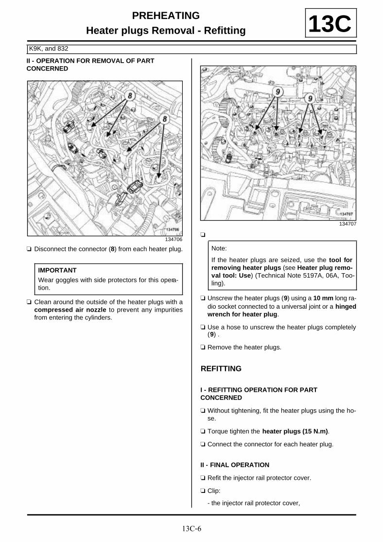
13C-6
PREHEATINGHeater plugs Removal - Refitting
K9K, and 832
13CII - OPERATION FOR REMOVAL OF PART CONCERNED
a Disconnect the connector (8) from each heater plug.
a Clean around the outside of the heater plugs with acompressed air nozzle to prevent any impuritiesfrom entering the cylinders.
a
a Unscrew the heater plugs (9) using a 10 mm long ra-dio socket connected to a universal joint or a hingedwrench for heater plug.
a Use a hose to unscrew the heater plugs completely(9) .
a Remove the heater plugs.
REFITTING
I - REFITTING OPERATION FOR PART CONCERNED
a Without tightening, fit the heater plugs using the ho-se.
a Torque tighten the heater plugs (15 N.m).
a Connect the connector for each heater plug.
II - FINAL OPERATION
a Refit the injector rail protector cover.
a Clip:
- the injector rail protector cover,
134706
IMPORTANT
Wear goggles with side protectors for this opera-tion.
134707
Note:
If the heater plugs are seized, use the tool forremoving heater plugs (see Heater plug remo-val tool: Use) (Technical Note 5197A, 06A, Too-ling).

13C-7
PREHEATINGHeater plugs Removal - Refitting
K9K, and 832
13C- the wiring of the camshaft position sensor anddamper valve onto the injector rail protector cover.
a Connect:
- the damper valve connector,
- the camshaft position sensor connector.
a Fit the intercooler air outlet pipe.
a Connect the intercooler air outlet pipe on the dampervalve.
a Torque tighten the intercooler air outlet pipe clipon the damper valve (5.5 N.m).
a Refit:
- the turbocharger air outlet pipe (see 12B, Turbo-charging, Intercooler air inlet pipe: Removal -Refitting, page 12B-41) ,
- the engine cover.

13C-8
PREHEATINGHeater plugs Removal - Refitting
K9K, and 830
13C
REMOVAL
I - REMOVAL PREPARATION OPERATION
a Remove:
- the engine cover,
- the turbocharger air outlet pipe (see 12B, Turbo-charging, Intercooler air inlet pipe: Removal -Refitting, page 12B-41) .
a Unclip the injector rail protector cover at (1) .
a Remove:
- the injector rail protector cover bolt (2) ,
- the injector rail protector cover,
II - OPERATION FOR REMOVAL OF PART CONCERNED
a Disconnect the connector (3) from each heater plug.
a Clean around the outside of the heater plugs with acompressed air nozzle to prevent any impuritiesfrom entering the cylinders.
Essential equipment
compressed air nozzle
tool for removing heater plugs
hinged wrench for heater plug
Tightening torquesm
heater plugs 15 N.m
135878
135861
IMPORTANT
Wear goggles with side protectors for this opera-tion.

13C-9
PREHEATINGHeater plugs Removal - Refitting
K9K, and 830
13C
a
a Unscrew the heater plugs (4) using a 10 mm long ra-dio socket connected to a universal joint or a hingedwrench for heater plug.
a Use a hose to unscrew the heater plugs completely(4) .
a Remove the heater plugs.
REFITTING
I - REFITTING OPERATION FOR PART CONCERNED
a Without tightening, fit the heater plugs using the ho-se.
a Torque tighten the heater plugs (15 N.m).
a Connect the connector for each heater plug.
II - FINAL OPERATION
a Refit the injector rail protector cover.
a Clip on the injector rail protector cover.
a Refit:
- the turbocharger air outlet pipe (see 12B, Turbo-charging, Intercooler air inlet pipe: Removal -Refitting, page 12B-41) ,
- the engine cover.
135860
Note:
If the heater plugs are seized, use the tool forremoving heater plugs (see Heater plug remo-val tool: Use) (Technical Note 5197A, 06A, Too-ling).

14A-1
ANTIPOLLUTIONFuel vapour canister: Removal - Refitting
F4R or K4M
14A
REMOVAL
I - REMOVAL PREPARATION OPERATION
a Position the vehicle on a two-post lift (see Vehicle:Towing and lifting) (02A, Lifting equipment).
II - OPERATION FOR REMOVAL OF PART CONCERNED
a Remove the fuel vapour absorber by pulling itdownwards then towards the vehicle exterior.
a Disconnect the fuel vapour absorber pipes (1) and(2) .
a Insert the blanking plugs.
a Remove the fuel vapour absorber.
IMPORTANT
During this operation, be sure to:
- refrain from smoking or bringing red hot objectsclose to the working area,
- be careful of fuel splashes when disconnecting theunion.
IMPORTANT
Wear leaktight gloves (Nitrile type) for this opera-tion.
IMPORTANT
Wear goggles with side protectors for this opera-tion.
WARNING
To avoid any corrosion or damage, protect theareas on which fuel is likely to run.
WARNING
Keep the pipe unions away from contaminatedareas.
WARNING
To prevent impurities from entering the circuit, placeprotective plugs on all fuel circuit componentsexposed to the open air.
102483
102483

14A-2
ANTIPOLLUTIONFuel vapour canister: Removal - Refitting
F4R or K4M
14AREFITTING
I - REFITTING PREPARATION OPERATION
a Remove the blanking plugs.
II - REFITTING OPERATION FOR PART CONCERNED
a Connect the fuel vapour absorber pipes.
a Refit the fuel vapour absorber on the tank.
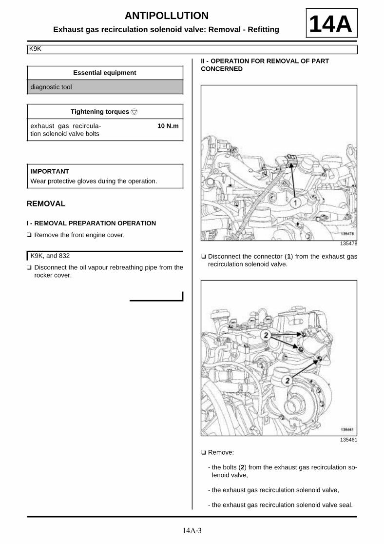
14A-3
ANTIPOLLUTIONExhaust gas recirculation solenoid valve: Removal - Refitting
K9K
14A
REMOVAL
I - REMOVAL PREPARATION OPERATION
a Remove the front engine cover.
a Disconnect the oil vapour rebreathing pipe from therocker cover.
II - OPERATION FOR REMOVAL OF PART CONCERNED
a Disconnect the connector (1) from the exhaust gasrecirculation solenoid valve.
a Remove:
- the bolts (2) from the exhaust gas recirculation so-lenoid valve,
- the exhaust gas recirculation solenoid valve,
- the exhaust gas recirculation solenoid valve seal.
Essential equipment
diagnostic tool
Tightening torquesm
exhaust gas recircula-tion solenoid valve bolts
10 N.m
IMPORTANT
Wear protective gloves during the operation.
K9K, and 832
135478
135461

14A-4
ANTIPOLLUTIONExhaust gas recirculation solenoid valve: Removal - Refitting
K9K
14AREFITTING
I - REFITTING PREPARATION OPERATION
a parts always to be replaced: exhaust gas recir-culation solenoid valve seal (11,07,01,13).
a Use a SURFACE CLEANER (see Vehicle: Parts and ingredients for the repairwork) (04B, Consu-mables - Products) to clean and degrease the sea-ling surfaces:
- of the exhaust gas recirculation solenoid valve if itis being reused,
- of the exhaust gas recirculation mounting on thegearbox side.
II - REFITTING OPERATION FOR PART CONCERNED
a Refit:
- a new seal on the exhaust gas recirculation sole-noid valve,
- the exhaust gas recirculation solenoid valve.
a Torque tighten the exhaust gas recirculation sole-noid valve bolts (10 N.m).
a Connect the exhaust gas recirculation solenoid val-ve connector.
III - FINAL OPERATION
a Connect the oil vapour rebreathing pipe onto therocker cover.
a Refit the engine cover.
a Apply the after repair procedure using the diagnos-tic tool :
- connect the diagnostic tool,
- select "Injection computer",
- go to repair mode,
- display the "Before/after repair procedure" for thecomputer selected,
- select "Exhaust gas recirculation solenoid valve" inthe "List of components controlled by this compu-ter" section,
- carry out the operations described in the "After re-pair procedure" section.
K9K, and 832

14A-5
ANTIPOLLUTIONExhaust gas recirculation solenoid valve: Removal - Refitting
F9Q
14A
REMOVAL
I - REMOVAL PREPARATION OPERATION
a Position the vehicle on a two-post lift (see Vehicle:Towing and lifting) (02A, Lifting equipment).
a Remove:
- the engine cover,
- the engine undertray bolts,
- the engine undertray,
- the windscreen wiper arms (see Windscreen wi-per arm: Removal - Refitting) (85A, Wiping -Washing),
- the scuttle panel grille (see Scuttle panel grille:Removal - Refitting) (56A, Exterior equipment),
- the scoop under the scuttle panel grille (see Scoopunder scuttle panel grille: Removal - Refitting)(56A, Exterior equipment),
- the battery (see Battery : Removal - Refitting)(80A, Battery),
- the battery tray (see Battery tray: Removal - Re-fitting) (80A, Battery),
- the intercooler air inlet pipe (see 12B, Turbochar-ging, Intercooler air inlet pipe: Removal - Refit-ting, page 12B-41) ,
- the exhaust gas recirculation rigid pipes (see 14A,Antipollution, Exhaust gas recirculation rigidpipe: Removal - Refitting, page 14A-30) ,
- the exhaust gas recirculation assembly (see 14A,Antipollution, Exhaust gas recirculation as-sembly: Removal - Refitting, page 14A-18) .
II - OPERATION FOR REMOVAL OF PART CONCERNED
a Remove:
- the bolts (1) from the exhaust gas recirculation so-lenoid valve,
- the exhaust gas recirculation solenoid valve,
- the exhaust gas recirculation solenoid valve seal.
REFITTING
I - REFITTING PREPARATION OPERATION
a parts always to be replaced: exhaust gas recir-culation solenoid valve seal (11,07,01,13).
a Use SURFACE CLEANER (see Vehicle: Parts and ingredients for the repairwork) (04B, Consu-mables - Products) to clean and degrease the joint face of:
- the exhaust gas cooler,
- the exhaust gas recirculation solenoid valve.
II - REFITTING OPERATION FOR PART CONCERNED
a Refit:
- a new seal on the exhaust gas recirculation sole-noid valve,
- the exhaust gas recirculation solenoid valve.
a Torque tighten the exhaust gas recirculation sole-noid valve bolts (10 N.m).
Tightening torquesm
exhaust gas recircula-tion solenoid valve bolts
10 N.m
136211

14A-6
ANTIPOLLUTIONExhaust gas recirculation solenoid valve: Removal - Refitting
F9Q
14AIII - FINAL OPERATION
a Refit:
- the exhaust gas recirculation assembly (see 14A,Antipollution, Exhaust gas recirculation as-sembly: Removal - Refitting, page 14A-18) ,
- the exhaust gas recirculation rigid pipes (see 14A,Antipollution, Exhaust gas recirculation rigidpipe: Removal - Refitting, page 14A-30) ,
- the intercooler air inlet pipe (see 12B, Turbochar-ging, Intercooler air inlet pipe: Removal - Refit-ting, page 12B-41) ,
- the battery tray (see Battery tray: Removal - Re-fitting) (80A, Battery),
- the battery (see Battery : Removal - Refitting)(80A, Battery),
- the scoop under the scuttle panel grille (see Scoopunder scuttle panel grille: Removal - Refitting)(56A, Exterior equipment),
- the scuttle panel grille (see Scuttle panel grille:Removal - Refitting) (56A, Exterior equipment),
- the windscreen wiper arms (see Windscreen wi-per arm: Removal - Refitting) (85A, Wiping -Washing),
- the engine undertray,
- the engine cover.
a Apply the after repair procedure using the diagnostic tool:
- connect the diagnostic tool,
- select « Injection computer » ,
- go to repair mode,
- display the « before/after repair procedure » for thecomputer selected,
- select « Exhaust gas recirculation solenoid valve »in the « List of components controlled by thiscomputer » section,
- carry out the operations described in the « After re-pair procedure » section.

14A-7
ANTIPOLLUTIONIntercooler: Removal - Refitting
K9K
14A
REMOVAL
I - REMOVAL PREPARATION OPERATION
a Position the vehicle on a two-post lift (see Vehicle:Towing and lifting) (02A, Lifting equipment).
a Disconnect the battery (see Battery : Removal -Refitting) (80A, Battery).
a Remove:
- the windscreen wiper arms (see Windscreen wi-per arm: Removal - Refitting) ,
- the scuttle panel grille (see Scuttle panel grille:Removal - Refitting) ,
- the brake fluid reservoir from the scoop under thescuttle panel grille,
- the scoop under the scuttle panel grille (see Scoopunder scuttle panel grille: Removal - Refitting) .
a Remove:
- the engine cover,
- the engine undertray bolts,
- the engine undertray,
- the catalytic converter (see 19B, Exhaust, Cataly-tic converter: Removal - Refitting, page 19B-17),
- the turbocharger air outlet pipe (see 12B, Turbo-charging, Intercooler air inlet pipe: Removal -Refitting, page 12B-41) .
a Remove the damper valve (see 12A, Fuel mixture,Air inlet flap: Removal - Refitting, page 12A-11) .
a Remove:
- the exhaust gas recirculation rigid pipe (see 14A,Antipollution, Exhaust gas recirculation rigidpipe: Removal - Refitting, page 14A-30) ,
- the exhaust gas recirculation assembly (see 14A,Antipollution, Exhaust gas recirculation as-sembly: Removal - Refitting, page 14A-18) .
Essential special tooling
Mot. 1448 Long nose pliers for hoseclips.
Ms. 583 Hose clamp pliers.
Tightening torquesm
exhaust gas cooler boltson the exhaust gasrecirculation mounting
12 N.m
bolts of the exhaust gasrecirculation rigid pipeon the exhaust gasrecirculation assembly
12 N.m
exhaust gas cooler boltson the exhaust gasrecirculation mounting
12 N.m
bolts of the exhaust gasrecirculation assemblymounting
12 N.m
bolts of the exhaust gasrecirculation assemblyon the cylinder head
25 N.m
bolts of the exhaust gasrecirculation rigid pipebracket on the cylinderhead
25 N.m
bolts of the exhaust gasrecirculation rigid pipeon the exhaust manifold
36 N.m
air filter unit air outletpipe clip on the turbo-charger
5.5 N.m
clip of the air filter unitair outlet pipe on the airfilter unit
5.5 N.m
J95
K9K, and 832

14A-8
ANTIPOLLUTIONIntercooler: Removal - Refitting
K9K
14AII - OPERATION FOR REMOVAL OF PART CONCERNED
a Remove the following on the workbench:
- the bolts (1) from the exhaust gas cooler,
- the exhaust gas cooler,
- the exhaust gas cooler seal.
a Remove:
- the bolts (2) from the exhaust gas recirculation as-sembly mounting on the timing end,
- the exhaust gas recirculation assembly mountingon the timing end,
- the exhaust gas recirculation assembly mountingseal on the timing end,
- the bolts (3) from the exhaust gas cooler,
K9K, and 832
135459
K9K, and 830
135841
135840
14A-9
ANTIPOLLUTIONIntercooler: Removal - Refitting
K9K
14A- the exhaust gas cooler,
- the exhaust gas cooler seal.
REFITTING
I - REFITTING PREPARATION OPERATION
a parts always to be replaced: exhaust gas coolerseal (11,07,01,17).
a parts always to be replaced: Exhaust gas recir-culation rigid pipe (11,07,01,08).
a parts always to be replaced: Exhaust gas recir-culation pipe seal (11,07,01,15).
a Use ABRASIVE PADS to clean the joint faces:
- of the exhaust gas cooler if it is being reused,
- of the exhaust gas recirculation mounting on thegearbox side.
a Use ABRASIVE PADS to clean the joint faces of theexhaust gas recirculation mounting on the timingend.
a Use SURFACE CLEANER (see Vehicle: Parts and ingredients for the repairwork) (04B, Consu-mables - Products) and CLEAN CLOTHS to de-grease the joint faces:
- of the exhaust gas cooler if it is being reused,
- of the exhaust gas recirculation mounting on thegearbox side.
a Use SURFACE CLEANER (see Vehicle: Partsand ingredients for the repairwork) (04B, Ingre-dient - Products) and CLEAN CLOTHS to degreasethe joint faces of the exhaust gas recirculationmounting on the timing end.
K9K, and 832
Note:
Take care not to damage the joint faces of theexhaust gas cooler on its mounting to preventany coolant leaks.
K9K, and 830
WARNINGTo ensure proper sealing, the gasket surfacesmust be clean, dry and not greasy (avoid any fin-ger marks).
K9K, and 830

14A-10
ANTIPOLLUTIONIntercooler: Removal - Refitting
K9K
14AII - REFITTING OPERATION FOR PART CONCERNED
a On the workbench, refit:
- the exhaust gas cooler with a new seal on the ex-haust gas recirculation mounting on the gearbox si-de,
- fit without tightening the exhaust gas cooler boltson the exhaust gas recirculation mounting on thegearbox side,
- the new exhaust gas recirculation rigid pipe on theexhaust gas recirculation assembly,
- fit without tightening the bolts of the exhaust gas re-circulation rigid pipe on the exhaust gas recircula-tion assembly.
a Fit the exhaust gas recirculation assembly equippedwith the exhaust gas recirculation rigid pipe on thecylinder head.
a Tighten:
- the bolts of the exhaust gas recirculation assemblyon the cylinder head,
- the bolts of the exhaust gas recirculation rigid pipebracket on the cylinder head,
- the bolts of the exhaust gas cooler on the exhaustgas recirculation mounting,
- the bolts of the exhaust gas recirculation rigid pipeon the exhaust gas recirculation assembly,
a Remove:
- the exhaust gas recirculation assembly bolts,
- the bolts of the exhaust gas recirculation rigid pipebracket,
- the exhaust gas recirculation assembly fitted withthe exhaust gas recirculation rigid pipe.
a On the workbench, torque tighten:
- the exhaust gas cooler bolts on the exhaust gasrecirculation mounting (12 N.m),
- the bolts of the exhaust gas recirculation rigidpipe on the exhaust gas recirculation assembly(12 N.m).
a On the workbench, refit:
- the exhaust gas cooler with a new seal on the ex-haust gas recirculation mounting on the gearbox si-de,
- fit without tightening the exhaust gas cooler bolts ofthe exhaust gas recirculation mounting on thegearbox side,
- the timing end exhaust gas recirculation assemblymounting on the exhaust gas recirculation assem-bly,
- fit without tightening the bolts of the timing end ex-haust gas recirculation assembly mounting on theexhaust gas recirculation assembly.
a Fit the exhaust gas recirculation assembly on the cy-linder head equipped with the exhaust gas recircula-tion assembly mounting.
a Tighten:
- the bolts of the exhaust gas recirculation assemblyon the cylinder head,
- the bolts of the exhaust gas recirculation assemblymounting on the cylinder head,
- the bolts of the exhaust gas cooler on the exhaustgas recirculation mounting,
- the bolts of the exhaust gas recirculation assemblymounting on the exhaust gas recirculation assem-bly,
a Remove:
- the bolts of the exhaust gas recirculation assemblyon the cylinder head,
- the bolts of the exhaust gas recirculation assemblymounting.
a On the workbench, torque tighten:
- the exhaust gas cooler bolts on the exhaust gasrecirculation mounting (12 N.m),
K9K, and 832
Note:
The exhaust gas cooler must be able to move inrelation to the exhaust gas recirculation mountingand the exhaust gas recirculation rigid pipe sothat it can be adjusted correctly.
K9K, and 830
Note:
The exhaust gas cooler must be able to move inrelation to the exhaust gas recirculation mountingand the exhaust gas recirculation rigid pipe sothat it can be adjusted correctly.

14A-11
ANTIPOLLUTIONIntercooler: Removal - Refitting
K9K
14A- the bolts of the exhaust gas recirculation as-sembly mounting (12 N.m).
III - FINAL OPERATION
a Refit the exhaust gas recirculation assembly (see14A, Antipollution, Exhaust gas recirculation as-sembly: Removal - Refitting, page 14A-18) .
a Refit the exhaust gas recirculation assembly equip-ped with the exhaust gas recirculation rigid pipe onthe cylinder head.
a Fit without tightening:
- the bolts of the exhaust gas recirculation assemblyon the cylinder head,
- the bolts of the exhaust gas recirculation rigid pipebracket on the cylinder head,
- the exhaust gas recirculation rigid pipe bolts on theexhaust manifold.
a Tighten to torque:
- the bolts of the exhaust gas recirculation as-sembly on the cylinder head (25 N.m),
- the bolts of the exhaust gas recirculation rigidpipe bracket on the cylinder head (25 N.m),
- the bolts of the exhaust gas recirculation rigidpipe on the exhaust manifold (36 N.m).
a Connect the cooling hoses of the exhaust gas coolercover.
a Fit the clip on each cooling hose of the exhaust gascooler cover using the tool (Mot. 1448).
a Remove the tool (Ms. 583) on each cooling hose ofthe exhaust gas cooler cover.
a Clip the hose of the turbocharging pressure regula-tion solenoid valve onto the exhaust gas cooler co-ver.
a Refit the air outlet pipe onto the air filter unit.
a Connect the air filter unit air outlet pipe to the turbo-charger.
a Torque tighten the air filter unit air outlet pipe clipon the turbocharger (5.5 N.m).
a Connect the air filter unit air outlet pipe to the air filterunit.
a Torque tighten the clip of the air filter unit air out-let pipe on the air filter unit (5.5 N.m).
a Clip the air flowmeter wiring onto the air filter unit airoutlet pipe.
K9K, and 830
K9K, and 832

14A-12
ANTIPOLLUTIONIntercooler: Removal - Refitting
K9K
14A
a Refit the rigid exhaust gas recirculation pipe (see14A, Antipollution, Exhaust gas recirculation ri-gid pipe: Removal - Refitting, page 14A-30) .
a Refit:
- the air inlet metal tube fitted with new seals,
- the lifting eye on the timing end.
a Connect the exhaust gas recirculation solenoid val-ve connector.
a Refit:
- the injector rail protector cover mounting,
- the injector rail protector cover.
a Clip the injector rail protector cover into place.
a Refit the damper valve (see 12A, Fuel mixture, Airinlet flap: Removal - Refitting, page 12A-11) .
a Refit:
- the turbocharger air outlet pipe (see 12B, Turbo-charging, Intercooler air inlet pipe: Removal -Refitting, page 12B-41) ,
- the oil vapour rebreathing pipe .
a Connect the oil vapour rebreathing pipe:
- on the rocker cover,
- on the air filter box air outlet pipe.
a Refit:
- the catalytic converter (see 19B, Exhaust, Cataly-tic converter: Removal - Refitting, page 19B-17),
- the engine undertray,
- the engine cover.
a Refit:
- the scoop under the scuttle panel grille (see Scoopunder scuttle panel grille: Removal - Refitting) .
- the brake fluid reservoir of the scoop under the scu-ttle panel grille,
- the scuttle panel grille (see Scuttle panel grille:Removal - Refitting) ,
- the windscreen wiper arms (see Windscreen wi-per arm: Removal - Refitting) .
a Connect the battery (see Battery : Removal - Refit-ting) (80A, Battery).
a Fill and bleed the cooling system (see 19A, Coo-ling, Cooling circuit: Draining - Refilling, page19A-17) .
K9K, and 830
K9K, and 832
K9K, and 832
J95

14A-13
ANTIPOLLUTIONIntercooler: Removal - Refitting
F9Q
14A
REMOVAL
I - REMOVAL PREPARATION OPERATION
a Position the vehicle on a two-post lift (see Vehicle:Towing and lifting) (02A, Lifting equipment).
a Remove:
- the engine cover,
- the engine undertray bolts,
- the engine undertray,
- the windscreen wiper arms (see Windscreen wi-per arm: Removal - Refitting) (85A, Wiping -Washing),
- the scuttle panel grille (see Scuttle panel grille:Removal - Refitting) (56A, Exterior equipment),
- the scoop under the scuttle panel grille (see Scoopunder scuttle panel grille: Removal - Refitting)(56A, Exterior equipment),
- the battery (see Battery : Removal - Refitting)(80A, Battery),
- the battery tray (see Battery tray: Removal - Re-fitting) (80A, Battery),
- the intercooler air inlet pipe (see 12B, Turbochar-ging, Intercooler air inlet pipe: Removal - Refit-ting, page 12B-41) ,
- the exhaust gas recirculation rigid pipes (see 14A,Antipollution, Exhaust gas recirculation rigidpipe: Removal - Refitting, page 14A-30) ,
- the exhaust gas recirculation assembly (see 14A,Antipollution, Exhaust gas recirculation as-sembly: Removal - Refitting, page 14A-18) .
II - OPERATION FOR REMOVAL OF PART CONCERNED
a Remove:
- the bolts (1) from the exhaust gas cooler,
- the exhaust gas cooler,
- the exhaust gas cooler seal.
REFITTING
I - REFITTING PREPARATION OPERATION
a parts always to be replaced: exhaust gas coolerseal (11,07,01,17).
a Use SURFACE CLEANER (see Vehicle: Parts and ingredients for the repairwork) (04B, Consu-mables - Products) to clean and degrease the joint faces:
- the exhaust gas cooler,
- the exhaust gas recirculation solenoid valve.
II - REFITTING OPERATION FOR PART CONCERNED
a Refit:
- a new exhaust gas cooler seal,
- the exhaust gas intercooler.
a Torque tighten the exhaust gas cooler bolts (10N.m).
Tightening torquesm
exhaust gas cooler bolts 10 N.m
136211
14A-14
ANTIPOLLUTIONIntercooler: Removal - Refitting
F9Q
14AIII - FINAL OPERATION
a Refit:
- the exhaust gas recirculation assembly (see 14A,Antipollution, Exhaust gas recirculation as-sembly: Removal - Refitting, page 14A-18) ,
- the exhaust gas recirculation rigid pipes (see 14A,Antipollution, Exhaust gas recirculation rigidpipe: Removal - Refitting, page 14A-30) ,
- the intercooler air inlet pipe (see 12B, Turbochar-ging, Intercooler air inlet pipe: Removal - Refit-ting, page 12B-41) ,
- the battery tray (see Battery tray: Removal - Re-fitting) (80A, Battery),
- the battery (see Battery : Removal - Refitting)(80A, Battery),
- the scoop under the scuttle panel grille (see Scoopunder scuttle panel grille: Removal - Refitting)(56A, Exterior equipment),
- the scuttle panel grille (see Scuttle panel grille:Removal - Refitting) (56A, Exterior equipment),
- the windscreen wiper arms (see Windscreen wi-per arm: Removal - Refitting) (85A, Wiping -Washing),
- the engine undertray,
- the engine cover.

14A-15
ANTIPOLLUTIONIntercooler: Removal - Refitting
K9K, and 836
14A
REMOVAL
I - REMOVAL PREPARATION OPERATION
a Position the vehicle on a two-post lift (see Vehicle:Towing and lifting) (02A, Lifting equipment).
a Disconnect the battery (see Battery: Removal - Re-fitting) (80A, Battery).
a Remove:
- the engine cover,
- the engine undertray bolts,
- the engine undertray,
- the exhaust gas recirculation rigid pipe (see 14A,Antipollution, Exhaust gas recirculation rigidpipe: Removal - Refitting, page 14A-30) ,
- the exhaust gas recirculation assembly (see 14A,Antipollution, Exhaust gas recirculation as-sembly: Removal - Refitting, page 14A-18) .
II - OPERATION FOR REMOVAL OF PART CONCERNED
a Remove:
- the exhaust gas pressure sensor clip,
- the exhaust gas pressure sensor.
a Remove the coolant hose clip between the exhaustgas cooler and the exhaust gas recirculation sole-noid valve.
a Disconnect the coolant hose at the exhaust gas coo-ler end.
Tightening torquesm
exhaust gas cooler boltson the exhaust gasrecirculation mounting
12 N.m
bolts of the exhaust gasrecirculation assemblymounting
12 N.m
100000-1
100000-1
14A-16
ANTIPOLLUTIONIntercooler: Removal - Refitting
K9K, and 836
14A
a Remove:
- the bolts from the exhaust gas recirculation assem-bly support,
- the exhaust gas recirculation assembly.
a Remove:
- the exhaust gas cooler bolts,
- the exhaust gas cooler.
REFITTING
I - REFITTING PREPARATION OPERATION
a parts always to be replaced: exhaust gas coolerseal (11,07,01,17)
a Use ABRASIVE PADS to clean the joint faces:
- of the exhaust gas cooler if it is being reused,
- of the exhaust gas recirculation mounting on thegearbox side.
a Use ABRASIVE PADS to clean the joint faces of theexhaust gas recirculation mounting on the timingend.
a Use SURFACE CLEANER (see Vehicle: Parts and consumables for repair) (04B, Consumables - Products) and CLEAN CLOTHS to degrease the joint faces:
- of the exhaust gas cooler if it is being reused,
- of the exhaust gas recirculation mounting on thegearbox side.
a Use SURFACE CLEANER (see Vehicle: Partsand consumables for repair) (04B, Ingredient -Products) and CLEAN CLOTHS to degrease thejoint faces of the exhaust gas recirculation supporton the timing end.
II - REFITTING OPERATION FOR PART CONCERNED
a On the workbench, refit the exhaust gas cooler witha new seal on the exhaust gas recirculation supporton the gearbox side.
a Fit without tightening the exhaust gas cooler bolts onthe exhaust gas recirculation support on the gearboxside.
a On the workbench, refit the timing end exhaust gasrecirculation assembly support on the exhaust gasrecirculation assembly.
100000-1
100000-1
Note:
Take care not to damage the joint faces of theexhaust gas cooler on its mounting to preventany coolant leaks.
WARNING
To ensure proper sealing, the gasket surfacesmust be clean, dry and not greasy (avoid any fin-ger marks).
14A-17
ANTIPOLLUTIONIntercooler: Removal - Refitting
K9K, and 836
14Aa Fit without tightening the bolts of the timing end ex-
haust gas recirculation assembly support on the ex-haust gas recirculation assembly.
a Connect the coolant hose to the exhaust gas cooler.
a Refit:
- the new coolant hose clip between the exhaust gascooler and the exhaust gas recirculation solenoidvalve,
- the exhaust gas pressure sensor,
- the exhaust gas pressure sensor clip.
a Fit the exhaust gas recirculation assembly on the cy-linder head equipped with the exhaust gas recircula-tion assembly mounting.
a Tighten:
- the bolts of the exhaust gas recirculation assemblyon the cylinder head,
- the bolts of the exhaust gas recirculation assemblymounting on the cylinder head,
- the bolts of the exhaust gas cooler on the exhaustgas recirculation support,
- the bolts of the exhaust gas recirculation assemblysupport on the exhaust gas recirculation assembly.
a Remove:
- the bolts of the exhaust gas recirculation assemblyon the cylinder head,
- the bolts of the exhaust gas recirculation assemblymounting.
a On the workbench, torque tighten the following:
- the exhaust gas cooler bolts on the exhaust gasrecirculation mounting (12 N.m),
- the bolts of the exhaust gas recirculation as-sembly mounting (12 N.m).
III - FINAL OPERATION
a Refit:
- the exhaust gas recirculation assembly (see 14A,Antipollution, Exhaust gas recirculation as-sembly: Removal - Refitting, page 14A-18) ,
- the exhaust gas recirculation rigid pipe (see 14A,Antipollution, Exhaust gas recirculation rigidpipe: Removal - Refitting, page 14A-30) ,
- the engine undertray,
- the engine cover.
a Connect the battery (see Battery: Removal - Refit-ting) (80A, Battery).
a Fill and bleed the cooling system (see 19A, Coo-ling, Cooling circuit: Draining - Refilling, page19A-17) .
Note:
The exhaust gas cooler must remain mobile inrelation to the exhaust gas recirculation supportso that it can be adjusted correctly.

14A-18
ANTIPOLLUTIONExhaust gas recirculation assembly: Removal - Refitting
K9K
14A
REMOVAL
I - REMOVAL PREPARATION OPERATION
a Position the vehicle on a two-post lift (see Vehicle:Towing and lifting) (02A, Lifting equipment).
a Disconnect the battery (see Battery : Removal -Refitting) (80A, Battery).
a Remove:
- the engine cover,
- the engine undertray bolts,
- the engine undertray,
- the catalytic converter (see 19B, Exhaust, Cataly-tic converter: Removal - Refitting, page 19B-17).
a Disconnect:
- the oil vapour rebreathing pipe union from the airfilter unit air outlet pipe,
- the oil vapour rebreathing pipe from the rocker co-ver.
a Remove the oil vapour rebreathing pipe.
Essential special tooling
Ms. 583 Hose clamp pliers.
Mot. 1448 Long nose pliers for hoseclips.
Tightening torquesm
bolts of the exhaust gasrecirculation assemblyon the cylinder head
25 N.m
bolts of the exhaust gasrecirculation rigid pipebracket on the cylinderhead
25 N.m
bolts of the exhaust gasrecirculation rigid pipeon the exhaust manifold
36 N.m
bolts of the exhaust gasrecirculation rigid pipeon the exhaust gasrecirculation assembly
12 N.m
bolts of the exhaust gasrecirculation assembly
25 N.m
bolts of the exhaust gasrecirculation assemblymounting
25 N.m
air filter unit air outletpipe clip on the turbo-charger
5.5 N.m
clip of the air filter unitair outlet pipe on the airfilter unit
5.5 N.m
IMPORTANT
Wear protective gloves during the operation.
K9K, and 832

14A-19
ANTIPOLLUTIONExhaust gas recirculation assembly: Removal - Refitting
K9K
14A
a Disconnect the oil vapour rebreathing pipe unionfrom the air filter unit air outlet pipe (1) .
a Separate the clip (2) of the oil vapour rebreathingpipe away on the oil vapour rebreathing valve.
a Disconnect the oil vapour rebreathing pipe from theoil vapour rebreathing valve.
a Remove the oil vapour rebreathing pipe.
a Remove the turbocharger outlet air pipe (see 12B,Turbocharging, Intercooler air inlet pipe: Remo-val - Refitting, page 12B-41) .
a Remove the damper valve (see 12A, Fuel mixture,Air inlet flap: Removal - Refitting, page 12A-11) .
K9K, and 830
135880
K9K, and 832

14A-20
ANTIPOLLUTIONExhaust gas recirculation assembly: Removal - Refitting
K9K
14A
a Remove the nut (3) from the breather mounting onthe gearbox.
a Move the breather mounting away from the gearbox.
a Remove:
- the bolts (4) of the oil vapour rebreathing valvebracket,
- the oil vapour rebreathing valve bracket.
a Disconnect the brake servo pipe union from the va-cuum pump.
a Remove:
- the nuts (5) of the oil vapour rebreathing valve,
- the oil vapour rebreathing valve.
K9K, and 830
135879
135845
112325

14A-21
ANTIPOLLUTIONExhaust gas recirculation assembly: Removal - Refitting
K9K
14A
a Unclip the injector rail protector cover at (6) .
a Remove:
- the injector rail protector cover bolt (7) ,
- the injector rail protector cover nut (8) ,
- the injector rail protector cover.
a Unclip the injector rail protector cover at (9) .
a Remove:
- the injector rail protector cover bolt (10) ,
- the injector rail protector cover.
a Remove:
- the injector rail protector cover mounting bolts (11),
- the injector rail protector cover mounting.
a Disconnect the connector (12) from the exhaust gasrecirculation solenoid valve.
K9K, and 832
134699
K9K, and 830
135878
134702
134705

14A-22
ANTIPOLLUTIONExhaust gas recirculation assembly: Removal - Refitting
K9K
14A
a Remove:
- the bolts (13) from the lifting eye at the timing end,
- the lifting eye on the timing end,
- the air inlet metal tube (14) ,
- the air inlet metal tube seals,
- the rigid exhaust gas recirculation pipe (see 14A,Antipollution, Exhaust gas recirculation rigidpipe: Removal - Refitting, page 14A-30) .
a Unclip the air flowmeter wiring from the air filter unitair outlet pipe at (15) .
a Loosen the clip (16) of the air filter unit air outlet pipefrom the air filter unit.
a Disconnect the air filter unit air outlet pipe from theair filter unit.
135463 134038

14A-23
ANTIPOLLUTIONExhaust gas recirculation assembly: Removal - Refitting
K9K
14A
a Undo the air filter unit air outlet pipe clip (17) fromthe turbocharger.
a Undo the air filter unit air outlet pipe clip (18) fromthe turbocharger.
a Disconnect the air filter unit air outlet pipe from theturbocharger.
a Remove the air outlet pipe from the air filter box.
a Unclip the hose of the turbocharging pressure regu-lation solenoid valve from the exhaust gas cooler co-ver.
K9K, and 832
135410
K9K, and 830
136639

14A-24
ANTIPOLLUTIONExhaust gas recirculation assembly: Removal - Refitting
K9K
14A
a Fit the tool (Ms. 583) on each cooling hose (19) ofthe exhaust gas cooler cover.
a Separate the clip (20) of each cooling hose of the ex-haust gas cooler cover (19) on the exhaust gas coo-ler cover using the tool (Mot. 1448).
a Disconnect the cooling hoses of the exhaust gascooler cover (20) from the exhaust gas cooler cover.
II - OPERATION FOR REMOVAL OF PART CONCERNED
a Remove:
- the bolts (21) from the exhaust gas recirculation as-sembly,
- the exhaust gas recirculation assembly.
a Remove:
- the bolts (22) of the exhaust gas recirculation as-sembly mounting,
135842
WARNING
Prepare for the flow of fluid, and protect the sur-rounding components.
K9K, and 832
135460
K9K, and 830
112329

14A-25
ANTIPOLLUTIONExhaust gas recirculation assembly: Removal - Refitting
K9K
14A- the bolts (23) from the exhaust gas recirculation as-sembly,
- the exhaust gas recirculation assembly.
REFITTING
I - REFITTING PREPARATION OPERATION
a Always replace the seals on the air inlet metal tube.
a Use ABRASIVE PADS to clean the joint faces of theexhaust gas cooler mounting on the gearbox end.
a Use SURFACE CLEANER (see Vehicle: Parts and ingredients for the repairwork) (04B, Consu-mables - Products) to clean and degrease:
- the housing of each air inlet metal tube seal,
- the housing of the air inlet metal tube in the cylinderhead,
- the housing of the air inlet metal tube in the ex-haust gas cooler mounting on the gearbox end.
a parts always to be replaced: Exhaust gas recir-culation rigid pipe (11,07,01,08).
a parts always to be replaced: Exhaust gas recir-culation pipe seal (11,07,01,15).
II - REFITTING OPERATION FOR PART CONCERNED
a Fit the new exhaust gas recirculation rigid pipe witha new seal on the exhaust gas recirculation assem-bly.
a Refit the exhaust gas recirculation assembly equip-ped with the exhaust gas recirculation rigid pipe onthe cylinder head.
a Fit without tightening:
- the bolts of the exhaust gas recirculation assemblyon the cylinder head,
- the bolts of the exhaust gas recirculation rigid pipebracket on the cylinder head,
- the exhaust gas recirculation rigid pipe bolts on theexhaust manifold.
a Tighten to torque:
- the bolts of the exhaust gas recirculation as-sembly on the cylinder head (25 N.m),
- the bolts of the exhaust gas recirculation rigidpipe bracket on the cylinder head (25 N.m),
- the bolts of the exhaust gas recirculation rigidpipe on the exhaust manifold (36 N.m),
- the bolts of the exhaust gas recirculation rigidpipe on the exhaust gas recirculation assembly(12 N.m).
a Refit the exhaust gas recirculation assembly.
a Tighten to torque:
- the bolts of the exhaust gas recirculation as-sembly (25 N.m),
- the bolts of the exhaust gas recirculation as-sembly mounting (25 N.m).
III - FINAL OPERATION
a Connect the cooling hoses of the exhaust gas coolercover.
a Fit the clip on each cooling hose of the exhaust gascooler cover using the tool (Mot. 1448).
WARNING
Do not scrape the joint faces of the aluminium,any damage caused to the joint face will result ina risk of leaks.
WARNING
To ensure proper sealing, the gasket surfacesmust be clean, dry and not greasy (avoid any fin-ger marks).
K9K, and 832
K9K, and 832
K9K, and 830

14A-26
ANTIPOLLUTIONExhaust gas recirculation assembly: Removal - Refitting
K9K
14Aa Remove the tool (Ms. 583) on each cooling hose of
the exhaust gas cooler cover.
a Clip the hose of the turbocharging pressure regula-tion solenoid valve onto the exhaust gas cooler co-ver.
a Refit the air outlet pipe onto the air filter unit.
a Connect the air filter unit air outlet pipe to the turbo-charger.
a Torque tighten the air filter unit air outlet pipe clipon the turbocharger (5.5 N.m).
a Connect the air filter unit air outlet pipe to the air filterunit.
a Torque tighten the clip of the air filter unit air out-let pipe on the air filter unit (5.5 N.m).
a Clip the air flowmeter wiring onto the air filter unit airoutlet pipe.
a Refit the rigid exhaust gas recirculation pipe (see14A, Antipollution, Exhaust gas recirculation ri-gid pipe: Removal - Refitting, page 14A-30) .
a Refit:
- the air inlet metal tube fitted with new seals,
- the lifting eye on the timing end.
a Connect the exhaust gas recirculation solenoid val-ve connector.
a Refit:
- the injector rail protector cover mounting,
- the injector rail protector cover.
a Clip the injector rail protector cover into place.
a Refit the damper valve (see 12A, Fuel mixture, Airinlet flap: Removal - Refitting, page 12A-11) .
a Refit the oil vapour rebreathing valve.
a Connect the brake servo pipe union to the vacuumpump.
a Refit the oil vapour rebreathing valve bracket.
a Fit the breather mounting on the gearbox.
a Refit the nut of the breather mounting on the gear-box.
a Refit:
- the turbocharger air outlet pipe (see 12B, Turbo-charging, Intercooler air inlet pipe: Removal -Refitting, page 12B-41) ,
- the oil vapour rebreathing pipe.
a Connect the oil vapour rebreathing pipe:
- on the rocker cover,
- on the air filter box air outlet pipe.
a Connect the oil vapour rebreathing pipe to the oil va-pour rebreathing valve.
a Fit the clip of the oil vapour rebreathing pipe on theoil vapour rebreathing valve.
a Connect the oil vapour rebreathing pipe union to theair filter unit air outlet pipe.
a Refit:
- the catalytic converter (see 19B, Exhaust, Cataly-tic converter: Removal - Refitting, page 19B-17),
- the engine undertray,
- the engine cover.
a Connect the battery (see Battery : Removal - Refit-ting) (80A, Battery).
a Fill and bleed the cooling system (see 19A, Coo-ling, Cooling circuit: Draining - Refilling, page19A-17) .
K9K, and 830
K9K, and 832
K9K, and 830
K9K, and 832
K9K, and 830
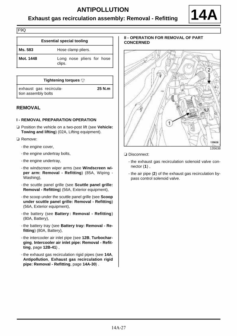
14A-27
ANTIPOLLUTIONExhaust gas recirculation assembly: Removal - Refitting
F9Q
14A
REMOVAL
I - REMOVAL PREPARATION OPERATION
a Position the vehicle on a two-post lift (see Vehicle:Towing and lifting) (02A, Lifting equipment).
a Remove:
- the engine cover,
- the engine undertray bolts,
- the engine undertray,
- the windscreen wiper arms (see Windscreen wi-per arm: Removal - Refitting) (85A, Wiping -Washing),
- the scuttle panel grille (see Scuttle panel grille:Removal - Refitting) (56A, Exterior equipment),
- the scoop under the scuttle panel grille (see Scoopunder scuttle panel grille: Removal - Refitting)(56A, Exterior equipment),
- the battery (see Battery : Removal - Refitting)(80A, Battery),
- the battery tray (see Battery tray: Removal - Re-fitting) (80A, Battery),
- the intercooler air inlet pipe (see 12B, Turbochar-ging, Intercooler air inlet pipe: Removal - Refit-ting, page 12B-41) ,
- the exhaust gas recirculation rigid pipes (see 14A,Antipollution, Exhaust gas recirculation rigidpipe: Removal - Refitting, page 14A-30) .
II - OPERATION FOR REMOVAL OF PART CONCERNED
a Disconnect:
- the exhaust gas recirculation solenoid valve con-nector (1) ,
- the air pipe (2) of the exhaust gas recirculation by-pass control solenoid valve.
Essential special tooling
Ms. 583 Hose clamp pliers.
Mot. 1448 Long nose pliers for hoseclips.
Tightening torquesm
exhaust gas recircula-tion assembly bolts
25 N.m
135638

14A-28
ANTIPOLLUTIONExhaust gas recirculation assembly: Removal - Refitting
F9Q
14A
a Fit the tools (Ms. 583) on the exhaust gas cooler ho-ses (3) .
a Separate the clips (4) on the exhaust gas cooler ho-ses using the tool (Mot. 1448).
a Disconnect the hoses from the exhaust gas cooler.
a Remove:
- the bolts (5) from the exhaust gas recirculation as-sembly,
- the exhaust gas recirculation assembly.
REFITTING
I - REFITTING OPERATION FOR PART CONCERNED
a Refit the exhaust gas recirculation assembly.
a Torque tighten the exhaust gas recirculation as-sembly bolts (25 N.m).
a Connect the exhaust gas cooler hoses.
a Fit the clips on the exhaust gas cooler hoses usingthe tool (Mot. 1448).
135542
135573
137462
135572
14A-29
ANTIPOLLUTIONExhaust gas recirculation assembly: Removal - Refitting
F9Q
14Aa Remove the tools (Ms. 583) from the exhaust gas
cooler hoses.
a Connect:
- the air pipe of the exhaust gas recirculation bypasscontrol solenoid valve,
- the exhaust gas recirculation solenoid valve con-nector.
II - FINAL OPERATION
a Refit:
- the exhaust gas recirculation rigid pipes (see 14A,Antipollution, Exhaust gas recirculation rigidpipe: Removal - Refitting, page 14A-30) ,
- the intercooler air inlet pipe (see 12B, Turbochar-ging, Intercooler air inlet pipe: Removal - Refit-ting, page 12B-41) ,
- the battery tray (see Battery tray: Removal - Re-fitting) (80A, Battery),
- the battery (see Battery : Removal - Refitting)(80A, Battery),
- the scoop under the scuttle panel grille (see Scoopunder scuttle panel grille: Removal - Refitting)(56A, Exterior equipment),
- the scuttle panel grille (see Scuttle panel grille:Removal - Refitting) (56A, Exterior equipment),
- the windscreen wiper arms (see Windscreen wi-per arm: Removal - Refitting) (85A, Wiping -Washing),
- the engine undertray,
- the engine cover.
a Bleed the cooling system (see 19A, Cooling, Coo-ling circuit: Draining - Refilling, page 19A-17) .

14A-30
ANTIPOLLUTIONExhaust gas recirculation rigid pipe: Removal - Refitting
K9K
14A
REMOVAL
I - REMOVAL PREPARATION OPERATION
a Position the vehicle on a two-post lift (see Vehicle:Towing and lifting) (02A, Lifting equipment).
a Disconnect the battery (see Battery : Removal -Refitting) (80A, Battery).
a Remove:
- the windscreen wiper arms (see Windscreen wi-per arm: Removal - Refitting) ,
- the scuttle panel grille (see Scuttle panel grille:Removal - Refitting) ,
- the brake fluid reservoir from the scoop under thescuttle panel grille,
- the scoop under the scuttle panel grille (see Scoopunder scuttle panel grille: Removal - Refitting) .
a Remove:
- the engine cover,
- the engine undertray bolts,
- the engine undertray,
- the catalytic converter (see 19B, Exhaust, Cataly-tic converter: Removal - Refitting, page 19B-17).
a Remove:
- the bolts (1) from the lifting eye at the timing end,
- the lifting eye on the timing end.
Tightening torquesm
bolts of the exhaust gasrecirculation rigid pipebracket on the cylinderhead
25 N.m
bolts of the exhaust gasrecirculation rigid pipeon the exhaust manifold
36 N.m
bolts of the exhaust gasrecirculation rigid pipeon the exhaust gasrecirculation assembly
12 N.m
exhaust gas recircula-tion pipe bolts
36 N.m
exhaust gas recircula-tion pipe clip
5 N.m
IMPORTANT
Wear protective gloves during the operation.
J95
K9K, and 832
135463

14A-31
ANTIPOLLUTIONExhaust gas recirculation rigid pipe: Removal - Refitting
K9K
14AII - OPERATION FOR REMOVAL OF PART CONCERNED
a Remove:
- the bolts (2) of the exhaust gas recirculation rigidpipe bracket from the cylinder head,
- the bolts (3) of the exhaust gas recirculation rigidpipe from the exhaust manifold,
- the bolts (4) of the exhaust gas recirculation rigidpipe from the exhaust gas recirculation assembly,
- the exhaust gas recirculation rigid pipe,
- the exhaust gas recirculation pipe rigid seal.
a Loosen the clip (5) of the exhaust gas recirculationrigid pipe from the exhaust gas recirculation assem-bly mounting.
a Remove:
- the bolts (6) from the EGR rigid pipe,
- the exhaust gas recirculation rigid pipe,
- the exhaust gas recirculation rigid pipe clip,
- the exhaust gas recirculation rigid pipe seal.
REFITTING
I - REFITTING PREPARATION OPERATION
a parts always to be replaced: Exhaust gas recir-culation rigid pipe (11,07,01,08).
a parts always to be replaced: Exhaust gas recir-culation pipe seal (11,07,01,15).
a parts always to be replaced: Exhaust gas recir-culation pipe clip (11,07,01,14).
K9K, and 832
135462
K9K, and 830
136647
K9K, and 830

14A-32
ANTIPOLLUTIONExhaust gas recirculation rigid pipe: Removal - Refitting
K9K
14Aa Use ABRASIVE PADS to clean the joint face of the
exhaust manifold.
a Use ABRASIVE PADS to clean the joint face of theexhaust gas recirculation assembly.
a Use SURFACE CLEANER (see Vehicle: Partsand ingredients for the repairwork) (04B, Consu-mables - Products) and CLEAN CLOTHS to de-grease the joint face of the exhaust manifold.
a Use SURFACE CLEANER (see Vehicle: Partsand ingredients for the repairwork) (04B, Consu-mables - Products) and CLEAN CLOTHS to de-grease the joint face of the exhaust gas recirculationassembly.
II - REFITTING OPERATION FOR PART CONCERNED
a Fit the new exhaust gas recirculation rigid pipe witha new seal.
a Fit without tightening:
- the bolts of the exhaust gas recirculation rigid pipeon the exhaust gas recirculation assembly,
- the bolts to the exhaust gas recirculation rigid pipeon the exhaust manifold,
- the bolts to the exhaust gas recirculation rigid pipebracket on the cylinder head.
a Tighten to torque:
- the bolts of the exhaust gas recirculation rigidpipe bracket on the cylinder head (25 N.m),
- the bolts of the exhaust gas recirculation rigidpipe on the exhaust manifold (36 N.m),
- the bolts of the exhaust gas recirculation rigidpipe on the exhaust gas recirculation assembly(12 N.m).
a Refit the new exhaust gas recirculation rigid pipewith a new seal and a new clip.
a Tighten to torque:
- the exhaust gas recirculation pipe bolts (36N.m),
- the exhaust gas recirculation pipe clip (5 N.m).
III - FINAL OPERATION
a Refit the engine lifting eye at the timing end.
a Refit:
- the catalytic converter (see 19B, Exhaust, Cataly-tic converter: Removal - Refitting, page 19B-17),
- the engine undertray,
WARNING
Do not scrape the joint faces of the aluminium,any damage caused to the joint face will result ina risk of leaks.
K9K, and 832
WARNING
To ensure proper sealing, the gasket surfacesmust be clean, dry and not greasy (avoid any fin-ger marks).
K9K, and 832
K9K, and 832
K9K, and 830
K9K, and 832

14A-33
ANTIPOLLUTIONExhaust gas recirculation rigid pipe: Removal - Refitting
K9K
14A- the engine cover.
a Refit:
- the scoop under the scuttle panel grille (see Scoopunder scuttle panel grille: Removal - Refitting) .
- the brake fluid reservoir of the scoop under the scu-ttle panel grille
- the scuttle panel grille (see Scuttle panel grille:Removal - Refitting) ,
- the windscreen wiper arms (see Windscreen wi-per arm: Removal - Refitting) .
a Connect the battery (see Battery : Removal - Refit-ting) (80A, Battery).
J95

14A-34
ANTIPOLLUTIONExhaust gas recirculation rigid pipe: Removal - Refitting
F9Q
14A
REMOVING THE EXHAUST GAS RECIRCULATION UPPER RIGID PIPE
I - REMOVAL PREPARATION OPERATION
a Remove the front engine cover.
II - OPERATION FOR REMOVAL OF PART CONCERNED
a Remove the bolts (1) from the exhaust gas recircula-tion upper rigid pipe.
a Loosen the clip (2) on the exhaust gas recirculationupper rigid pipe.
a Remove:
- the exhaust gas recirculation upper rigid pipe,
- the seal of the exhaust gas recirculation upper rigidpipe,
- the clip of the exhaust gas recirculation upper rigidpipe.
REFITTING THE EXHAUST GAS RECIRCULATION UPPER RIGID PIPE
I - REFITTING PREPARATION OPERATION
a parts always to be replaced: Exhaust gas recir-culation pipe clip (11,07,01,14).
parts always to be replaced: Exhaust gas recir-culation pipe seal (11,07,01,15).
a Use SURFACE CLEANER (see Vehicle: Parts and ingredients for the repairwork) (04B, Consu-mables - Products) to clean and degrease the joint faces:
- the exhaust gas recirculation solenoid valve,
- the intercooler air outlet pipe.
II - REFITTING OPERATION FOR PART CONCERNED
a Refit:
- a new seal of the exhaust gas recirculation upperrigid pipe,
- a new clip of the exhaust gas recirculation upper ri-gid pipe,
- the exhaust gas recirculation upper rigid pipe.
a Torque tighten the EGR upper rigid pipe bolts (25N.m).
III - FINAL OPERATION
a Refit the engine cover.
REMOVING THE EXHAUST GAS RECIRCULATION LOWER RIGID PIPE
I - REMOVAL PREPARATION OPERATION
a Position the vehicle on a two-post lift (see Vehicle:Towing and lifting) (02A, Lifting equipment).
a Remove:
- the engine cover,
- the engine undertray bolts,
- the engine undertray,
- the windscreen wiper arms (see Windscreen wi-per arm: Removal - Refitting) (85A, Wiping -Washing),
Essential special tooling
Mot. 1567 Long nose pliers for EGRduct clips.
Tightening torquesm
EGR upper rigid pipebolts
25 N.m
EGR lower rigid pipebolts
30 N.m
135543
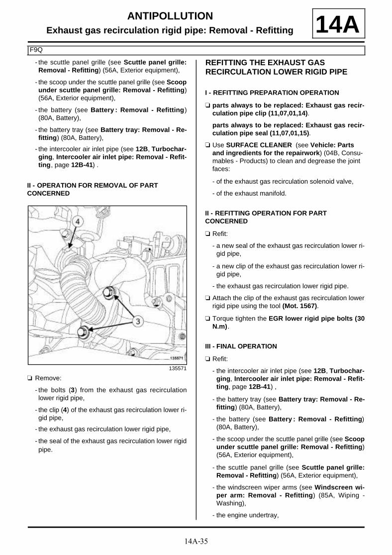
14A-35
ANTIPOLLUTIONExhaust gas recirculation rigid pipe: Removal - Refitting
F9Q
14A- the scuttle panel grille (see Scuttle panel grille:Removal - Refitting) (56A, Exterior equipment),
- the scoop under the scuttle panel grille (see Scoopunder scuttle panel grille: Removal - Refitting)(56A, Exterior equipment),
- the battery (see Battery : Removal - Refitting)(80A, Battery),
- the battery tray (see Battery tray: Removal - Re-fitting) (80A, Battery),
- the intercooler air inlet pipe (see 12B, Turbochar-ging, Intercooler air inlet pipe: Removal - Refit-ting, page 12B-41) .
II - OPERATION FOR REMOVAL OF PART CONCERNED
a Remove:
- the bolts (3) from the exhaust gas recirculationlower rigid pipe,
- the clip (4) of the exhaust gas recirculation lower ri-gid pipe,
- the exhaust gas recirculation lower rigid pipe,
- the seal of the exhaust gas recirculation lower rigidpipe.
REFITTING THE EXHAUST GAS RECIRCULATION LOWER RIGID PIPE
I - REFITTING PREPARATION OPERATION
a parts always to be replaced: Exhaust gas recir-culation pipe clip (11,07,01,14).
parts always to be replaced: Exhaust gas recir-culation pipe seal (11,07,01,15).
a Use SURFACE CLEANER (see Vehicle: Parts and ingredients for the repairwork) (04B, Consu-mables - Products) to clean and degrease the joint faces:
- of the exhaust gas recirculation solenoid valve,
- of the exhaust manifold.
II - REFITTING OPERATION FOR PART CONCERNED
a Refit:
- a new seal of the exhaust gas recirculation lower ri-gid pipe,
- a new clip of the exhaust gas recirculation lower ri-gid pipe,
- the exhaust gas recirculation lower rigid pipe.
a Attach the clip of the exhaust gas recirculation lowerrigid pipe using the tool (Mot. 1567).
a Torque tighten the EGR lower rigid pipe bolts (30N.m).
III - FINAL OPERATION
a Refit:
- the intercooler air inlet pipe (see 12B, Turbochar-ging, Intercooler air inlet pipe: Removal - Refit-ting, page 12B-41) ,
- the battery tray (see Battery tray: Removal - Re-fitting) (80A, Battery),
- the battery (see Battery : Removal - Refitting)(80A, Battery),
- the scoop under the scuttle panel grille (see Scoopunder scuttle panel grille: Removal - Refitting)(56A, Exterior equipment),
- the scuttle panel grille (see Scuttle panel grille:Removal - Refitting) (56A, Exterior equipment),
- the windscreen wiper arms (see Windscreen wi-per arm: Removal - Refitting) (85A, Wiping -Washing),
- the engine undertray,
135571

14A-36
ANTIPOLLUTIONExhaust gas recirculation rigid pipe: Removal - Refitting
F9Q
14A- the engine cover.

14A-37
ANTIPOLLUTIONExhaust gas recirculation rigid pipe: Removal - Refitting
K9K, and 836
14AREMOVAL
I - REMOVAL PREPARATION OPERATION
a Position the vehicle on a two-post lift (see Vehicle:Towing and lifting) (02A, Lifting equipment).
a Remove:
- the engine cover,
- the engine undertray bolts,
- the engine undertray.
a Undo:
- the air filter unit air outlet pipe clip (1) on the air fil-ter unit,
- the air filter unit air outlet pipe clip (2) on the turbo-charger air inlet pipe.
a Remove the air filter unit air outlet pipe.
a Unclip the turbocharging pressure regulation sole-noid valve hose from the turbocharger air inlet pipeat (3) .
a Remove the turbocharger air inlet pipe bolt from theexhaust gas recirculation assembly (4) .
100000-1
100000-1
100000-1

14A-38
ANTIPOLLUTIONExhaust gas recirculation rigid pipe: Removal - Refitting
K9K, and 836
14A
a Disconnect the oil vapour rebreathing pipe from therocker cover (5) .
a Remove:
- the turbocharger air inlet pipe bolts (6) from the tur-bocharger,
- the turbocharger air inlet pipe.
a Remove:
- the bolt (7) of the intermediate air pipe between theturbocharger and the intercooler,
- the nut (8) for the intermediate air pipe between theturbocharger and the intercooler,
- the clip (9) of the intermediate air pipe between theturbocharger and the intercooler.
a Remove the intermediate air pipe between the tur-bocharger and the intercooler.
a Remove:
- the clip (10) of the turbocharger air outlet pipe,
100000-1
100000-1
137183
100000-1

14A-39
ANTIPOLLUTIONExhaust gas recirculation rigid pipe: Removal - Refitting
K9K, and 836
14A- the turbocharger air outlet pipe.
a Remove the turbocharger outlet exhaust gas duct(see 12B, Turbocharging, Turbocharger outletexhaust gas duct: Removal - Refitting, page 12B-49) .
II - OPERATION FOR REMOVAL OF PART CONCERNED
a Remove:
- the exhaust gas recirculation rigid pipe clip (11)from the exhaust manifold,
- the exhaust gas recirculation rigid pipe clip (12)from the exhaust gas recirculation assembly,
- the EGR rigid pipe.
REFITTING
I - REFITTING PREPARATION OPERATION
a parts always to be replaced: Exhaust gas recir-culation rigid pipe (11,07,01,08).
a parts always to be replaced: Exhaust gas recir-culation pipe clip (11,07,01,14).
a Using ABRASIVE PADS, clean the bearing face of:
- the exhaust manifold,
- the exhaust gas recirculation assembly support.
a Using SURFACE CLEANER (see Vehicle: Parts and ingredients for the repairwork) (04B, Consu-mables - Products) and CLEAN CLOTHS, degrease the bearing face of:
- the exhaust manifold,
- the exhaust gas recirculation assembly support.
II - REFITTING OPERATION FOR PART CONCERNED
a Fit the new exhaust gas recirculation rigid pipe.
a Refit a new exhaust gas recirculation rigid pipe clip on:
- the exhaust manifold,
- the exhaust gas recirculation assembly support.
III - FINAL OPERATION
a Refit the turbocharger outlet exhaust gas duct (see12B, Turbocharging, Turbocharger outlet ex-haust gas duct: Removal - Refitting, page 12B-49) .
a Refit:
- the turbocharger air outlet pipe clip to the turbo-charger air outlet pipe,
- the turbocharger air outlet pipe to the turbocharger.
a Fit the intermediate air pipe between the turbochar-ger and the intercooler.
a Refit the clip for the intermediate air pipe betweenthe turbocharger and the intercooler.
a Clip the intermediate air pipe between the turbochar-ger and the intercooler onto the turbocharger air out-let pipe.
a Refit:
- the nut of the intermediate air pipe between the tur-bocharger and the intercooler,
- the bolt of the intermediate air pipe between theturbocharger and the intercooler,
- the turbocharger air inlet pipe,
- he turbocharger air inlet pipe bolts on the turbo-charger.
a Connect the oil vapour rebreathing pipe onto therocker cover.
a Refit the turbocharger air inlet pipe bolt onto the ex-haust gas recirculation assembly.
a Clip the turbocharging pressure regulation solenoidvalve hose onto the turbocharger air inlet pipe.
a Refit the air outlet pipe onto the air filter unit.
100000-1

14A-40
ANTIPOLLUTIONExhaust gas recirculation rigid pipe: Removal - Refitting
K9K, and 836
14Aa Tighten the clip of the air filter unit air outlet pipe on:
- the turbocharger air inlet pipe,
- the air filter unit.
a Refit:
- the engine undertray,
- the engine cover.
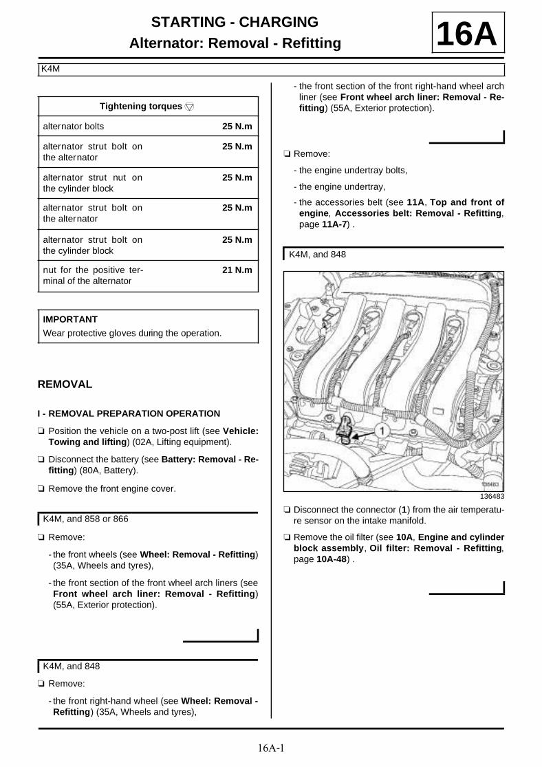
16A-1
STARTING - CHARGINGAlternator: Removal - Refitting
K4M
16A
REMOVAL
I - REMOVAL PREPARATION OPERATION
a Position the vehicle on a two-post lift (see Vehicle:Towing and lifting) (02A, Lifting equipment).
a Disconnect the battery (see Battery: Removal - Re-fitting) (80A, Battery).
a Remove the front engine cover.
a Remove:
- the front wheels (see Wheel: Removal - Refitting)(35A, Wheels and tyres),
- the front section of the front wheel arch liners (seeFront wheel arch liner: Removal - Refitting)(55A, Exterior protection).
a Remove:
- the front right-hand wheel (see Wheel: Removal -Refitting) (35A, Wheels and tyres),
- the front section of the front right-hand wheel archliner (see Front wheel arch liner: Removal - Re-fitting) (55A, Exterior protection).
a Remove:
- the engine undertray bolts,
- the engine undertray,
- the accessories belt (see 11A, Top and front ofengine, Accessories belt: Removal - Refitting,page 11A-7) .
a Disconnect the connector (1) from the air temperatu-re sensor on the intake manifold.
a Remove the oil filter (see 10A, Engine and cylinderblock assembly, Oil filter: Removal - Refitting,page 10A-48) .
Tightening torquesm
alternator bolts 25 N.m
alternator strut bolt onthe alternator
25 N.m
alternator strut nut onthe cylinder block
25 N.m
alternator strut bolt onthe alternator
25 N.m
alternator strut bolt onthe cylinder block
25 N.m
nut for the positive ter-minal of the alternator
21 N.m
IMPORTANT
Wear protective gloves during the operation.
K4M, and 858 or 866
K4M, and 848
K4M, and 848
136483

16A-2
STARTING - CHARGINGAlternator: Removal - Refitting
K4M
16A
a Remove:
- the front bumper (see Front bumper: Removal -Refitting) (55A, Exterior protection),
- the air deflectors,
- the headlights (see Front headlight: Removal -Refitting) (80B, Headlights),
- the front bumper mountings (see Front bumpersupport: Removal - Refitting) (42A, Front upperstructure),
- the audible warning (see Horn: Removal - Refit-ting) (82B, Horn),
- the front impact cross member (see Front impactcross member: Removal - Refitting) (41A, Frontlower structure),
- the bonnet catch (see Bonnet latch: Removal -Refitting) (52A, Non-side opening element mecha-nisms),
- the engine wiring channel from the cooling fan as-sembly.
a Unclip the hoses from the cooling fan assembly.
a Remove:
- the upper bolts (2) from the front end panel,
- the front end panel upper clips (3) .
a the front end panel lower bolts (4) .
a Move aside the front end panel.
K4M, and 858 or 866
135719
135713
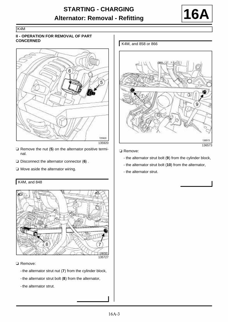
16A-3
STARTING - CHARGINGAlternator: Removal - Refitting
K4M
16AII - OPERATION FOR REMOVAL OF PART CONCERNED
a Remove the nut (5) on the alternator positive termi-nal.
a Disconnect the alternator connector (6) .
a Move aside the alternator wiring.
a Remove:
- the alternator strut nut (7) from the cylinder block,
- the alternator strut bolt (8) from the alternator,
- the alternator strut.
a Remove:
- the alternator strut bolt (9) from the cylinder block,
- the alternator strut bolt (10) from the alternator,
- the alternator strut.
135920
K4M, and 848
135727
K4M, and 858 or 866
136573
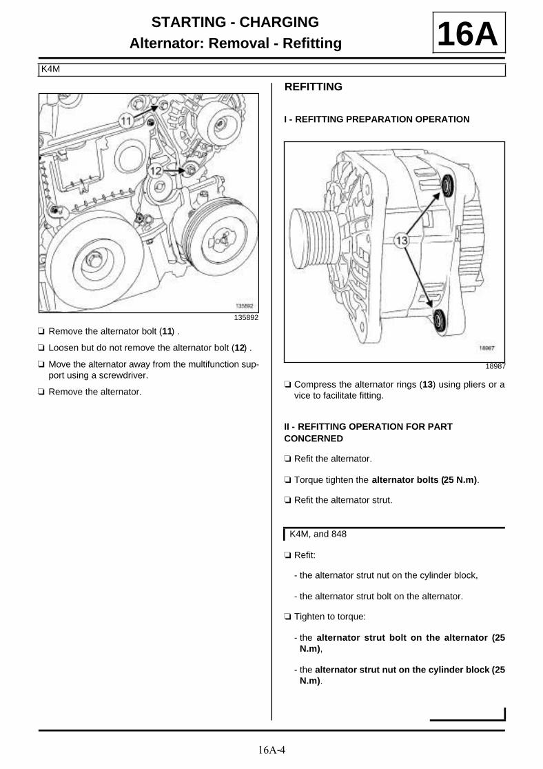
16A-4
STARTING - CHARGINGAlternator: Removal - Refitting
K4M
16A
a Remove the alternator bolt (11) .
a Loosen but do not remove the alternator bolt (12) .
a Move the alternator away from the multifunction sup-port using a screwdriver.
a Remove the alternator.
REFITTING
I - REFITTING PREPARATION OPERATION
a Compress the alternator rings (13) using pliers or avice to facilitate fitting.
II - REFITTING OPERATION FOR PART CONCERNED
a Refit the alternator.
a Torque tighten the alternator bolts (25 N.m).
a Refit the alternator strut.
a Refit:
- the alternator strut nut on the cylinder block,
- the alternator strut bolt on the alternator.
a Tighten to torque:
- the alternator strut bolt on the alternator (25N.m),
- the alternator strut nut on the cylinder block (25N.m).
135892
18987
K4M, and 848
16A-5
STARTING - CHARGINGAlternator: Removal - Refitting
K4M
16A
a Refit:
- the alternator strut bolt on the cylinder block,
- the alternator strut bolt on the alternator.
a Tighten to torque:
- the alternator strut bolt on the alternator (25N.m),
- the alternator strut bolt on the cylinder block(25 N.m).
a Position the wiring on the alternator.
a Attach the connector to the alternator.
a Refit the wiring on the alternator positive terminal.
a Torque tighten the nut for the positive terminal ofthe alternator (21 N.m).
III - FINAL OPERATION
a Fit the front end panel.
a Refit:
- the upper bolts on the front end panel,
- the lower bolts on the front end panel,
- the upper clips on the front end panel.
a Clip the hoses on the cooling fan assembly.
a Refit:
- the engine wiring channel on the cooling fan as-sembly,
- the bonnet catch (see Bonnet latch: Removal -Refitting) (52A, Non-side opening element mecha-nisms),
- the front impact cross member (see Front impactcross member: Removal - Refitting) (41A, Frontlower structure),
- the audible warning (see Horn: Removal - Refit-ting) (82B, Horn),
- the front bumper mountings (see Front bumpersupport: Removal - Refitting) (42A, Front upperstructure),
- the headlights (see Front headlight: Removal -Refitting) (80B, Headlights),
- the air deflectors,
- the front bumper (see Front bumper: Removal -Refitting) (55A, Exterior protection).
a Refit the oil filter (see 10A, Engine and cylinderblock assembly, Oil filter: Removal - Refitting,page 10A-48) .
a Connect the connector of the air temperature sensoron the intake manifold.
a Refit:
- the accessories belt (see 11A, Top and front ofengine, Accessories belt: Removal - Refitting,page 11A-7) ,
- the engine undertray.
a Refit:
- the front section of the front wheel arch liners (seeFront wheel arch liner: Removal - Refitting)(55A, Exterior protection),
- the front wheels (see Wheel: Removal - Refitting)(35A, Wheels and tyres).
a Refit:
- the front section of the front right-hand wheel archliner (see Front wheel arch liner: Removal - Re-fitting) (55A, Exterior protection),
- the front right-hand wheel (see Wheel: Removal -Refitting) (35A, Wheels and tyres).
a Refit the engine cover.
a Connect the battery (see Battery: Removal - Refit-ting) (80A, Battery).
K4M, and 858 or 866
K4M, and 858 or 866
K4M, and 848
K4M, and 858 or 866
K4M, and 848

16A-6
STARTING - CHARGINGAlternator: Removal - Refitting
K9K
16A
REMOVAL
I - REMOVAL PREPARATION OPERATION
a Position the vehicle on a two-post lift (see Vehicle:Towing and lifting) (02A, Lifting equipment).
a Disconnect the battery (see Battery : Removal -Refitting) (80A, Battery).
a Remove:
- the engine cover,
- the front wheels (see Wheel: Removal - Refitting)(35A, Wheels and tyres),
- the front section of the front wheel arch liners (seeFront wheel arch liner: Removal - Refitting)(55A, Exterior protection),
- the engine undertray bolts,
- the engine undertray,
- the accessories belt (see 11A, Top and front ofengine, Accessories belt: Removal - Refitting,page 11A-7) ,
- the front bumper (see Front bumper: Removal -Refitting) (55A, Exterior protection),
- the turbocharger air outlet pipe (see 12B, Turbo-charging, Intercooler air inlet pipe: Removal -Refitting, page 12B-41) ,
- the headlights (see Front headlight: Removal -Refitting) (80B, Headlights),
- the front bumper mountings (see Front bumpersupport: Removal - Refitting) (42A, Front upperstructure),
- the top air deflector of the cooling radiator,
- the side air deflectors of the cooling radiator,
- the audible warning (see Horn: Removal - Refit-ting) (82B, Horn),
- the front impact cross member (see Front impactcross member: Removal - Refitting) (41A, Frontlower structure),
- the bonnet catch (see Bonnet latch: Removal -Refitting) (52A, Non-side opening element mecha-nisms).
a Unclip the expansion bottle top hose (1) from thefront end panel.
a Remove the engine wiring channel bolts (2) from thefront end panel.
Tightening torquesm
alternator bolts 25 N.m
alternator positive termi-nal nut
8 N.m
IMPORTANT
Wear protective gloves during the operation.
135883
135882

16A-7
STARTING - CHARGINGAlternator: Removal - Refitting
K9K
16A
a Remove:
- the front end panel clips (3) ,
- the front end panel upper bolts (4) .
a Remove the lower bolts (5) from the front end panel.
a Tilt the front end panel towards the front of the vehi-cle.
a Unclip the expansion bottle bottom cooling hose (6)from the high pressure pump protector.
a Unclip the alternator wiring from the injector rail pro-tector.
II - OPERATION FOR REMOVAL OF PART CONCERNED
a Disconnect the alternator excitation connector (7) .
a Remove the nut (8) from the alternator positive ter-minal.
a Move aside the alternator wiring.
135719
135881
135884
135408

16A-8
STARTING - CHARGINGAlternator: Removal - Refitting
K9K
16A
a Undo the alternator bolts (9) .
a Remove the alternator bolts (9) as far as possible.
a Move the alternator away from the multifunction sup-port using a screwdriver.
a Remove the alternator with its bolts.
REFITTING
I - REFITTING PREPARATION OPERATION
a Compress the alternator rings (11) using pliers and avice to facilitate fitting.
II - REFITTING OPERATION FOR PART CONCERNED
a Refit the alternator equipped with its bolts.
a Torque tighten the alternator bolts (25 N.m).
a Position the alternator wiring.
a Refit the alternator positive terminal nut.
a Torque tighten the alternator positive terminal nut(8 N.m).
a Connect the alternator excitation connector.
III - FINAL OPERATION
a Clip:
- the alternator wiring on the injector rail protector,
- the expansion bottle bottom cooling hose on thehigh pressure pump protector.
a Fit the front end panel.
a Refit:
- the lower bolts from the front end panel,
- the front end panel upper bolts,
- the front end panel clips.
123831
18987

16A-9
STARTING - CHARGINGAlternator: Removal - Refitting
K9K
16A- the bolts of the engine cooling fan assembly wiringchannel on the front end panel.
a Clip the expansion bottle top hose onto the front endpanel.
a Refit:
- the bonnet catch (see Bonnet latch: Removal -Refitting) (52A, Non-side opening element mecha-nisms),
- the front impact cross member (see Front impactcross member: Removal - Refitting) (41A, Frontlower structure),
- the audible warning (see Horn: Removal - Refit-ting) (82B, Horn),
- the side air deflectors of the cooling radiator,
- the top air deflector of the cooling radiator,
- the front bumper mountings (see Front bumpersupport: Removal - Refitting) (42A, Front upperstructure).
- the headlights (see Front headlight: Removal -Refitting) (80B, Headlights),
- the turbocharger air outlet pipe (see 12B, Turbo-charging, Intercooler air inlet pipe: Removal -Refitting, page 12B-41) ,
- the front bumper (see Front bumper: Removal -Refitting) (55A, Exterior protection),
- the accessories belt (see 11A, Top and front ofengine, Accessories belt: Removal - Refitting,page 11A-7) ,
- the engine undertray,
- the front section of the front wheel arch liners (seeFront wheel arch liner: Removal - Refitting)(55A, Exterior protection),
- the front wheels (see Wheel: Removal - Refitting)(35A, Wheels and tyres),
- the engine cover.
a Connect the battery (see Battery : Removal - Refit-ting) (80A, Battery).

16A-10
STARTING - CHARGINGAlternator: Removal - Refitting
F9Q
16A
REMOVAL
I - REMOVAL PREPARATION OPERATION
a Position the vehicle on a two-post lift (see Vehicle:Towing and lifting) (02A, Lifting equipment).
a Disconnect the battery (see Battery : Removal -Refitting) (80A, Battery).
a Remove:
- the engine cover,
- the engine undertray bolts,
- the engine undertray,
- the front wheels (see Wheel: Removal - Refitting)(35A, Wheels and tyres),
- the front section of the front wheel arch liners (seeFront wheel arch liner: Removal - Refitting)(55A, Exterior protection),
- the front bumper (see Front bumper: Removal -Refitting) (55A, Exterior protection),
- the front impact cross member (see Front impactcross member: Removal - Refitting) (41A, Frontlower structure),
- the cooling radiator air deflectors.
- the headlights (see Front headlight: Removal -Refitting) (80B, Headlights),
- the front bumper mountings (see Front bumpersupport: Removal - Refitting) (42A, Front upperstructure),
- the accessories belt (see 11A, Top and front ofengine, Accessories belt: Removal - Refitting,page 11A-7) .
a Remove:
- the bolts (1) of the engine wiring channel,
- the bonnet catch (see Bonnet latch: Removal -Refitting) (52A, Non-side opening element mecha-nisms).
Tightening torquesm
alternator bolts 25 N.m
alternator positive termi-nal nut
24 N.m
135647

16A-11
STARTING - CHARGINGAlternator: Removal - Refitting
F9Q
16A
a Remove the front end panel bolts (2) .
a Tilt the front end panel.
a Remove the intercooler air outlet pipe (see 12B,Turbocharging, Intercooler air outlet pipe: Re-moval - Refitting, page 12B-56) .
II - OPERATION FOR REMOVAL OF PART CONCERNED
a Disconnect the connector (3) from the alternator re-gulator.
a Remove the nut (4) from the alternator positive ter-minal.
a Move aside the alternator wiring.
a Remove:
- the alternator bolts (5) ,
- the alternator.
135645
135646
135650
135651

16A-12
STARTING - CHARGINGAlternator: Removal - Refitting
F9Q
16AREFITTING
I - REFITTING PREPARATION OPERATION
a Compress the alternator rings (6) using pliers or avice to facilitate fitting.
II - REFITTING OPERATION FOR PART CONCERNED
a Refit the alternator.
a Torque tighten the alternator bolts (25 N.m).
a Position the alternator wiring.
a Torque tighten the alternator positive terminal nut(24 N.m).
a Connect the alternator regulator connector.
III - FINAL OPERATION
a Refit a new intercooler air outlet pipe (see 12B, Tur-bocharging, Intercooler air outlet pipe: Removal- Refitting, page 12B-56) .
a Refit:
- the front panel,
- the bonnet catch (see Bonnet latch: Removal -Refitting) (52A, Non-side opening element mecha-nisms),
- the bolts for the engine wiring harness channel,
- the accessories belt (see 11A, Top and front ofengine, Accessories belt: Removal - Refitting,page 11A-7) ,
- the front bumper mountings (see Front bumpersupport: Removal - Refitting) (42A, Front upperstructure),
- the front impact cross member (see Front impactcross member: Removal - Refitting) (41A, Frontlower structure),
- the headlights (see Front headlight: Removal -Refitting) (80B, Headlights),
- the front bumper (see Front bumper: Removal -Refitting) (55A, Exterior protection),
- the front section of the front wheel arch liners (seeFront wheel arch liner: Removal - Refitting)(55A, Exterior protection),
- the front wheels (see Wheel: Removal - Refitting)(35A, Wheels and tyres),
- the engine undertray,
- the engine cover.
a Connect the battery (see Battery : Removal - Refit-ting) (80A, Battery).
18987

16A-13
STARTING - CHARGINGAlternator: Removal - Refitting
F4R
16A
REMOVAL
I - REMOVAL PREPARATION OPERATION
a Position the vehicle on a two-post lift (see Vehicle:Towing and lifting) (02A, Lifting equipment).
a Disconnect the battery (see Battery : Removal -Refitting) (80A, Battery).
a Remove:
- the engine cover,
- the engine undertray bolts,
- the engine undertray,
- the front wheels (see Wheel: Removal - Refitting)(35A, Wheels and tyres),
- the front section of the front wheel arch liners (seeFront wheel arch liner: Removal - Refitting)(55A, Exterior protection),
- the front bumper (see Front bumper: Removal -Refitting) (55A, Exterior protection),
- the upper air deflector,
- the side air deflectors,
- the accessories belt (see 11A, Top and front ofengine, Accessories belt: Removal - Refitting,page 11A-7) ,
- the headlights (see Front headlight: Removal -Refitting) (80B, Headlights),
- the front bumper mountings (see Front bumpersupport: Removal - Refitting) (42A, Front upperstructure),
- the audible warning (see Horn: Removal - Refit-ting) (82B, Horn),
- the front impact cross member (see Front impactcross member: Removal - Refitting) (41A, Frontlower structure),
- the bonnet catch (see Bonnet latch: Removal -Refitting) (52A, Non-side opening element mecha-nisms).
a Unclip the cooling system degassing hose.
a Remove the bolts (2) of the wiring channel from theengine cooling fan assembly.
a Remove:
- the upper bolts (3) from the front end panel,
- the front end panel clips (4) .
Tightening torquesm
alternator bolts 25 N.m
alternator positive termi-nal nut
8 N.m
IMPORTANT
Wear protective gloves during the operation.
135736
135719
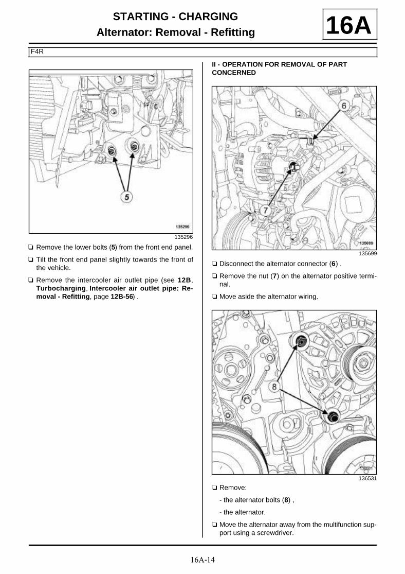
16A-14
STARTING - CHARGINGAlternator: Removal - Refitting
F4R
16A
a Remove the lower bolts (5) from the front end panel.
a Tilt the front end panel slightly towards the front ofthe vehicle.
a Remove the intercooler air outlet pipe (see 12B,Turbocharging, Intercooler air outlet pipe: Re-moval - Refitting, page 12B-56) .
II - OPERATION FOR REMOVAL OF PART CONCERNED
a Disconnect the alternator connector (6) .
a Remove the nut (7) on the alternator positive termi-nal.
a Move aside the alternator wiring.
a Remove:
- the alternator bolts (8) ,
- the alternator.
a Move the alternator away from the multifunction sup-port using a screwdriver.
135296
135699
136531

16A-15
STARTING - CHARGINGAlternator: Removal - Refitting
F4R
16AREFITTING
I - REFITTING PREPARATION OPERATION
a Compress the alternator rings (9) using pliers or avice to facilitate fitting.
II - REFITTING OPERATION FOR PART CONCERNED
a Refit the alternator.
a Torque tighten the alternator bolts (25 N.m).
a Position the alternator wiring.
a Torque tighten the alternator positive terminal nut(8 N.m).
a Connect the alternator connector.
III - FINAL OPERATION
a Refit the intercooler air outlet pipe (see 12B, Turbo-charging, Intercooler air outlet pipe: Removal -Refitting, page 12B-56) .
a Fit the front end panel.
a Tighten the front end panel bolts.
a Refit the front end panel clips.
a Clip on the expansion bottle degassing hose.
a Refit:
- the bolts of the wiring channel of the engine coolingfan assembly,
- the bonnet catch (see Front bumper support: Re-moval - Refitting) (52A, Non-side opening ele-ment mechanisms),
- the audible warning (see Horn: Removal - Refit-ting) (82B, Horn),
- the front impact cross member (see Front impactcross member: Removal - Refitting) (41A, Frontlower structure),
- the front bumper mountings (see Front bumpersupport: Removal - Refitting) (42A, Front upperstructure),
- the headlights (see Front headlight: Removal -Refitting) (80B, Headlights),
- the accessories belt (see 11A, Top and front ofengine, Accessories belt: Removal - Refitting,page 11A-7) ,
- the side air deflectors,
- the upper air deflector,
- the front bumper (see Front bumper: Removal -Refitting) (55A, Exterior protection),
- the front section of the front wheel arch liners (seeFront wheel arch liner: Removal - Refitting)(55A, Exterior protection),
- the front wheels (see Wheel: Removal - Refitting)(35A, Wheels and tyres),
- the engine undertray,
- the engine cover.
a Connect the battery (see Battery : Removal - Refit-ting) (80A, Battery).
18987

16A-16
STARTING - CHARGINGStarter: Removal - Refitting
K4M, and 848
16A
REMOVAL
I - REMOVAL PREPARATION OPERATION
a Position the vehicle on a two-post lift (see Vehicle:Towing and lifting) (02A, Lifting equipment).
a Disconnect the battery (see Battery: Removal - Re-fitting) (80A, Battery).
a Remove the front engine cover.
a Loosen the clip on the throttle valve air inlet pipe.
a Disconnect the air outlet pipe from the air filter unit.
a Remove:
- the air outlet pipe to the air filter unit,
- the gearbox lifting eye (1) ,
- the engine undertray bolts,
- the engine undertray,
a Disconnect the connector (2) from the oil level sen-sor.
a Move aside the wiring of the oil level sensor.
a Remove:
- the exhaust manifold strut nut (3) from the exhaustmanifold,
- the exhaust manifold strut bolt (4) from the cylinderblock,
Tightening torquesm
starter supply wiring nut 8 N.m
starter excitation wiringnut
5 N.m
exhaust manifold staynut on the exhaustmanifold
44 N.m
exhaust manifold staybolt on the cylinderblock
44 N.m
clip on the throttle valveair inlet pipe
6 N.m
135239
135916
136470

16A-17
STARTING - CHARGINGStarter: Removal - Refitting
K4M, and 848
16A- the exhaust manifold strut.
a Remove:
- the starter feed wiring nut (5) ,
- the starter excitation wiring nut (6) .
a Move the starter wiring aside.
II - OPERATION FOR REMOVAL OF PART CONCERNED
a Remove:
- the starter bolts (7) ,
- the starter.
REFITTING
I - REFITTING PREPARATION OPERATION
a Check that the centring dowel is in place.
II - REFITTING OPERATION FOR PART CONCERNED
a Refit the starter.
III - FINAL OPERATION
a Fit the starter wiring.
a Tighten to torque:
- the starter supply wiring nut (8 N.m),
- the starter excitation wiring nut (5 N.m).
a Refit the exhaust manifold stay.
a Tighten to torque:
- the exhaust manifold stay nut on the exhaustmanifold (44 N.m),
- the exhaust manifold stay bolt on the cylinderblock (44 N.m).
a Fit the oil level sensor wiring.
a Connect the connector to the oil level sensor.
a Refit:
- the engine undertray,
- the gearbox lifting eye,
- the air outlet pipe of the air filter unit.
a Connect the air outlet pipe of the air filter unit.
a Torque tighten the clip on the throttle valve air in-let pipe (6 N.m).
a Refit the engine cover.
a Connect the battery (see Battery: Removal - Refit-ting) (80A, Battery).
135917
135915

16A-18
STARTING - CHARGINGStarter: Removal - Refitting
K9K
16A
REMOVAL
I - REMOVAL PREPARATION OPERATION
a Position the vehicle on a two-post lift (see Vehicle:Towing and lifting) (02A, Lifting equipment).
a Remove:
- the engine cover,
- the engine undertray bolts,
- the engine undertray.
a Disconnect the battery (see Battery : Removal -Refitting) (80A, Battery).
a Remove the intercooler air outlet pipe (see 12B,Turbocharging, Intercooler air outlet pipe: Re-moval - Refitting, page 12B-56) .
a Disconnect:
- the connector (1) from the oil pressure sensor,
- the connector (2) from the oil level sensor.
a Loosen the nut on the starter solenoid (3) .
a Remove the nut of the starter supply terminal (4) .
a Move the starter wiring aside.
II - OPERATION FOR REMOVAL OF PART CONCERNED
a Remove:
- the starter bolts (5) ,
- the starter.
Tightening torquesm
starter bolts 44 N.m
starter supply terminalnut
8 N.m
nut on the starter sole-noid
5 N.m
123835
135407
135480

16A-19
STARTING - CHARGINGStarter: Removal - Refitting
K9K
16AREFITTING
I - REFITTING PREPARATION OPERATION
a When replacing the starter, remove the starter pro-tective shield.
a Refit the starter protective shield on a new starter.
a Check that the starter centring dowel is in place.
II - REFITTING OPERATION FOR PART CONCERNED
a Refit the starter.
a Torque tighten the starter bolts (44 N.m).
III - FINAL OPERATION
a Fit the starter wiring.
a Tighten to torque:
- the starter supply terminal nut (8 N.m).
- the nut on the starter solenoid (5 N.m).
a Connect:
- the oil level sensor connector,
- the oil pressure sensor connector.
a Refit the intercooler air outlet pipe (see 12B, Turbo-charging, Intercooler air outlet pipe: Removal -Refitting, page 12B-56) .
a Connect the battery (see Battery : Removal - Refit-ting) (80A, Battery).
a Refit:
- the engine undertray,
- the engine cover.

16A-20
STARTING - CHARGINGStarter: Removal - Refitting
K4M, and 858 or 866
16A
REMOVALa Disconnect the battery (see Battery: Removal - Re-
fitting) (80A, Battery).
a Remove:
- the engine undertray bolts,
- the engine undertray.
a Disconnect the connector (1) from the oil level sen-sor.
OPERATION FOR REMOVAL OF PART CONCERNED
a Remove:
- the starter supply cable nut (2) ,
- the starter excitation cable nut (3) .
a Move the starter wiring aside.
a Remove:
- the starter bolts (4) ,
- the starter.
Tightening torquesm
starter bolts 44 N.m
starter supply cable nut 8 N.m
starter excitation cablenut
5 N.m
136566
136565
136556
16A-21
STARTING - CHARGINGStarter: Removal - Refitting
K4M, and 858 or 866
16AREFITTING
I - REFITTING PREPARATION OPERATION
a Check that the centring dowel is in place.
II - REFITTING OPERATION FOR PART CONCERNED
a Refit the starter.
a Torque tighten the starter bolts (44 N.m).
a Fit the starter wiring.
a Tighten to torque:
- the starter supply cable nut (8 N.m),
- the starter excitation cable nut (5 N.m).
III - FINAL OPERATION
a Connect:
- the oil level sensor connector,
- the battery (see Battery: Removal - Refitting)(80A, Battery).
a Refit the engine undertray.

16A-22
STARTING - CHARGINGStarter: Removal - Refitting
F9Q
16A
REMOVAL
I - REMOVAL PREPARATION OPERATION
a Position the vehicle on a two-post lift (see Vehicle:Towing and lifting) (02A, Lifting equipment).
a Remove:
- the engine cover,
- the engine undertray bolts,
- the engine undertray,
- the windscreen wiper arms (see Windscreen wi-per arm: Removal - Refitting) (85A, Wiping -Washing),
- the scuttle panel grille (see Scuttle panel grille:Removal - Refitting) (56A, Exterior equipment),
- the scoop under the scuttle panel grille (see Scoopunder scuttle panel grille: Removal - Refitting)(56A, Exterior equipment),
- the battery (see Battery : Removal - Refitting)(80A, Battery),
- the battery tray (see Battery tray: Removal - Re-fitting) (80A, Battery),
- the intercooler air inlet pipe (see 12B, Turbochar-ging, Intercooler air inlet pipe: Removal - Refit-ting, page 12B-41) ,
- the lower engine tie-bar (see 19D, Engine moun-ting, Lower engine tie-bar: Removal - Refitting,page 19D-33) ,
- the turbocharger outlet exhaust gas duct (see 12B,Turbocharging, Turbocharger outlet exhaustgas duct: Removal - Refitting, page 12B-49) .
II - OPERATION FOR REMOVAL OF PART CONCERNED
a Remove:
- the starter supply cable nut,
- the starter excitation cable nut.
a Move the starter wiring aside.
a Remove:
- the starter bolts (1) ,
- the starter.
REFITTING
I - REFITTING PREPARATION OPERATION
a Check that the centring dowel is in place.
Tightening torquesm
starter excitation cablenut
5 N.m
starter supply cable nut 8 N.m
135643
135644

16A-23
STARTING - CHARGINGStarter: Removal - Refitting
F9Q
16AII - REFITTING OPERATION FOR PART CONCERNED
a Refit the starter.
a Fit the starter wiring.
a Tighten to torque:
- the starter excitation cable nut (5 N.m),
- the starter supply cable nut (8 N.m).
III - FINAL OPERATION
a Refit:
- the turbocharger outlet exhaust gas duct (see 12B,Turbocharging, Turbocharger outlet exhaustgas duct: Removal - Refitting, page 12B-49) ,
- the lower engine tie-bar (see 19D, Engine moun-ting, Lower engine tie-bar: Removal - Refitting,page 19D-33) ,
- the intercooler air inlet pipe (see 12B, Turbochar-ging, Intercooler air inlet pipe: Removal - Refit-ting, page 12B-41) ,
- the battery tray (see Battery tray: Removal - Re-fitting) (80A, Battery),
- the battery (see Battery : Removal - Refitting)(80A, Battery),
- the scoop under the scuttle panel grille (see Scoopunder scuttle panel grille: Removal - Refitting)(56A, Exterior equipment),
- the scuttle panel grille (see Scuttle panel grille:Removal - Refitting) (56A, Exterior equipment),
- the windscreen wiper arms (see Windscreen wi-per arm: Removal - Refitting) (85A, Wiping -Washing),
- the engine undertray,
- the engine cover.

16A-24
STARTING - CHARGINGStarter: Removal - Refitting
F4R
16A
REMOVAL
I - REMOVAL PREPARATION OPERATION
a Position the vehicle on a two-post lift (see Vehicle:Towing and lifting) (02A, Lifting equipment).
a Disconnect the battery (see Battery : Removal -Refitting) (80A, Battery).
a Remove:
- the windscreen wiper arms (see Windscreen wi-per arm: Removal - Refitting) (85A, Wiping -Washing),
- the scuttle panel grille (see Scuttle panel grille:Removal - Refitting) (56A, Exterior equipment),
- the scoop under the scuttle panel grille (see Scoopunder scuttle panel grille: Removal - Refitting)(56A, Exterior equipment),
- the timing end lifting eye bolt,
- the lifting eye on the timing end,
- the front right-hand wheel (see Wheel: Removal -Refitting) (35A, Wheels and tyres),
- the front section of the front right-hand wheel archliner (see Front wheel arch liner: Removal - Re-fitting) (55A, Exterior protection),
- the lower engine tie-bar (see 19D, Engine moun-ting, Lower engine tie-bar: Removal - Refitting,page 19D-33) ,
- the connecting hose (see 19B, Exhaust, Connec-ting hose: Removal - Refitting, page 19B-60) ,
- the engine undertray bolts,
- the engine undertray,
- the catalytic converter (see 19B, Exhaust, Cataly-tic converter: Removal - Refitting, page 19B-17).
a Remove:
- the nuts (1) from the starter heat shield,
- the starter heat shield.
Tightening torquesm
nut on the positive ter-minal of the starter
8 N.m
nut on the starter excita-tion terminal
7 N.m
120228
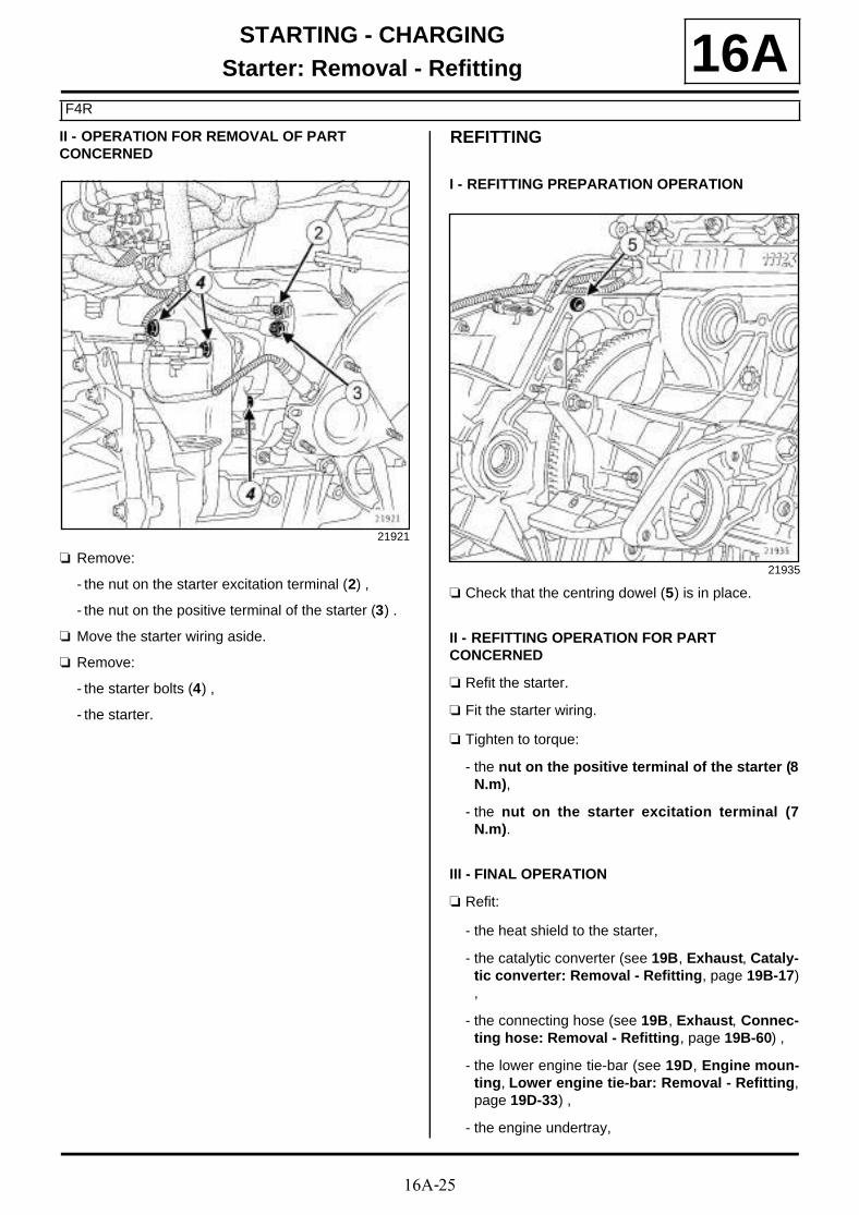
16A-25
STARTING - CHARGINGStarter: Removal - Refitting
F4R
16AII - OPERATION FOR REMOVAL OF PART CONCERNED
a Remove:
- the nut on the starter excitation terminal (2) ,
- the nut on the positive terminal of the starter (3) .
a Move the starter wiring aside.
a Remove:
- the starter bolts (4) ,
- the starter.
REFITTING
I - REFITTING PREPARATION OPERATION
a Check that the centring dowel (5) is in place.
II - REFITTING OPERATION FOR PART CONCERNED
a Refit the starter.
a Fit the starter wiring.
a Tighten to torque:
- the nut on the positive terminal of the starter (8N.m),
- the nut on the starter excitation terminal (7N.m).
III - FINAL OPERATION
a Refit:
- the heat shield to the starter,
- the catalytic converter (see 19B, Exhaust, Cataly-tic converter: Removal - Refitting, page 19B-17),
- the connecting hose (see 19B, Exhaust, Connec-ting hose: Removal - Refitting, page 19B-60) ,
- the lower engine tie-bar (see 19D, Engine moun-ting, Lower engine tie-bar: Removal - Refitting,page 19D-33) ,
- the engine undertray,
21921
21935
16A-26
STARTING - CHARGINGStarter: Removal - Refitting
F4R
16A- the front section of the front right-hand wheel archliner (see Front wheel arch liner: Removal - Re-fitting) (55A, Exterior protection),
- the front right-hand wheel (see Wheel: Removal -Refitting) (35A, Wheels and tyres),
- the lifting eye on the timing end,
- the scoop under the scuttle panel grille (see Scoopunder scuttle panel grille: Removal - Refitting)(56A, Exterior equipment),
- the scuttle panel grille (see Scuttle panel grille:Removal - Refitting) (56A, Exterior equipment),
- the windscreen wiper arms (see Windscreen wi-per arm: Removal - Refitting) (85A, Wiping -Washing),
a Connect the battery (see Battery : Removal - Refit-ting) (80A, Battery).

17A-1
IGNITIONCoils Removal - Refitting
F4R
17A
REMOVAL
I - REMOVAL PREPARATION OPERATION
a Remove the front engine cover.
II - OPERATION FOR REMOVAL OF PART CONCERNED
a Disconnect the coil connectors (1) .
a Disconnect the connector (2) from the camshaft de-phaser solenoid valve.
a Remove the coil bolts (3) .
a Move aside the camshaft dephaser solenoid valve.
a Remove the coils.
Tightening torquesm
coil bolts 12 N.m
134238
135750
136528
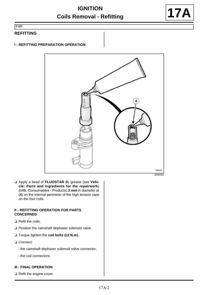
17A-2
IGNITIONCoils Removal - Refitting
F4R
17AREFITTING
I - REFITTING PREPARATION OPERATION
a Apply a bead of FLUOSTAR 2L grease (see Vehi-cle: Parts and ingredients for the repairwork)(04B, Consumables - Products) 2 mm in diameter at(4) on the internal perimeter of the high tension capson the four coils.
II - REFITTING OPERATION FOR PARTS CONCERNED
a Refit the coils.
a Position the camshaft dephaser solenoid valve.
a Torque tighten the coil bolts (12 N.m).
a Connect:
- the camshaft dephaser solenoid valve connector,
- the coil connectors.
III - FINAL OPERATION
a Refit the engine cover.
106443

17A-3
IGNITIONCoils Removal - Refitting
K4M
17A
REMOVAL
I - REMOVAL PREPARATION OPERATION
a Remove the front engine cover.
II - OPERATION FOR REMOVAL OF PART CONCERNED
a Disconnect the coil connectors (1) .
a Remove:
- the coil bolts (2) ,
- the coils.
Tightening torquesm
coil bolts 14 N.m
136482

17A-4
IGNITIONCoils Removal - Refitting
K4M
17AREFITTING
I - REFITTING PREPARATION OPERATION
a Apply a bead of FLUOSTAR 2L grease (3) (see Ve-hicle: Parts and ingredients for the repairwork)(04B, Consumables - Products) 2 mm in diameteron the internal perimeter of the high tension caps onthe four coils.
a Always replace the coil bolts.
II - REFITTING OPERATION FOR PART CONCERNED
a Refit the coils equipped with new bolts.
a Torque tighten the coil bolts (14 N.m).
a Connect the connectors to the coils.
III - FINAL OPERATION
a Refit the engine cover.
106443

17A-5
IGNITIONSpark plugs: Removal - Refitting
K4M
17A
REMOVAL
I - REMOVAL PREPARATION OPERATION
a Remove:
- the engine cover,
- the coils (see 17A, Ignition, Coils Removal - Re-fitting, page 17A-1) .
II - OPERATION FOR REMOVAL OF PART CONCERNED
a Remove the spark plugs using the (Ele. 1382) (1) .
REFITTING
I - REFITTING OPERATION FOR PART CONCERNED
a Refit the plugs.
a Torque tighten the spark plugs (25 N.m) using thetool (Ele. 1382).
II - FINAL OPERATION
a Refit:
- the coils (see 17A, Ignition, Coils Removal - Re-fitting, page 17A-1) ,
- the engine cover.
Essential special tooling
Ele. 1382 Spark plug spanner toolkit 16& 21 mm torque 1.75 & 28Nm + square adapter 9-9.52for spanner Ele. 1086
Tightening torquesm
spark plugs 25 N.m
136921
Note:
Use the limited torque wrench of (Ele. 1382) withthe grey sleeve.
17A-6
IGNITIONSpark plugs: Removal - Refitting
F4R
17A
REMOVAL
I - REMOVAL PREPARATION OPERATION
a Remove:
- the engine cover,
- the coils (see 17A, Ignition, Coils Removal - Re-fitting, page 17A-1) .
II - OPERATION FOR REMOVAL OF PART CONCERNED
a Remove the spark plugs using the (Ele. 1382).
REFITTING
I - REFITTING OPERATION FOR PART CONCERNED
a Refit the plugs.
a Torque tighten the spark plugs (28 N.m) using the(Ele. 1382).
II - FINAL OPERATION
a Refit:
- the coils (see 17A, Ignition, Coils Removal - Re-fitting, page 17A-1) ,
- the engine cover.
Essential special tooling
Ele. 1382 Spark plug spanner toolkit 16& 21 mm torque 1.75 & 28Nm + square adapter 9-9.52for spanner Ele. 1086
Tightening torquesm
spark plugs 28 N.m
Note:
Use the limited torque wrench of (Ele. 1382) withthe grey sleeve.

17A-7
IGNITIONSpark plugs: Removal - Refitting
K4M
17A
REMOVAL
I - REMOVAL PREPARATION OPERATION
a Remove:
- the engine cover,
- the coils (see 17A, Ignition, Coils Removal - Re-fitting, page 17A-1) .
II - OPERATION FOR REMOVAL OF PART CONCERNED
a Remove the spark plugs using the (Ele. 1382).
REFITTING
I - REFITTING OPERATION FOR PART CONCERNED
a Refit the plugs.
a Torque tighten the plugs (25 N.m) using the tool(Ele. 1382).
II - FINAL OPERATION
a Refit:
- the coils (see 17A, Ignition, Coils Removal - Re-fitting, page 17A-1) ,
- the engine cover.
Essential special tooling
Ele. 1382 Spark plug spanner toolkit 16& 21 mm torque 1.75 & 28Nm + square adapter 9-9.52for spanner Ele. 1086
Tightening torquesm
plugs 25 N.m
136921
Note:
Use the limited torque wrench of (Ele. 1382) withthe grey sleeve.

17B-1
PETROL INJECTIONOxygen sensors: Removal - Refitting
K4M
17B
REMOVING THE UPSTREAM OXYGEN SENSOR
I - REMOVAL PREPARATION OPERATION
a Remove:
- the engine cover,
- the windscreen wiper arms (see Windscreen wi-per arm: Removal - Refitting) (85A, Wiping -Washing),
- the scuttle panel grille (see Scuttle panel grille:Removal - Refitting) (56A, Exterior equipment),
- the scoop under the scuttle panel grille (see Scoopunder scuttle panel grille: Removal - Refitting)(56A, Exterior equipment),
- the throttle valve (see 12A, Fuel mixture, Throttlevalve: Removal - Refitting, page 12A-17) ,
- the intake distributor (see 12A, Fuel mixture, Inletmanifold: Removal - Refitting, page 12A-23) .
II - OPERATION FOR REMOVAL OF PART CONCERNED
a Unclip the upstream oxygen sensor connector (1) .
a Disconnect the upstream oxygen sensor connector.
a Remove the upstream oxygen sensor (2) using the(Mot. 1495-01).
Essential special tooling
Mot. 1495-01 22 mm socket for removing/refitting oxygen sensors.
WARNING
Do not use any product designed to improve theelectrical contact in the injection computer and oxy-gen sensor connectors or on the bodies of the oxy-gen sensors.
Failure to respect this advice causes the oxygensensor to malfunction and results in failure to com-ply with the emission control standard.
WARNING
If the connections are corroded, repair the wiring(see Wiring: Precautions for repair) (TechnicalNote 6015A, 88A, Wiring).
Note:
This procedure is for removal - refitting of the ups-tream oxygen sensor and the downstream oxygensensor.
136546
135938

17B-2
PETROL INJECTIONOxygen sensors: Removal - Refitting
K4M
17BREFITTING THE UPSTREAM OXYGEN SENSOR
I - REFITTING OPERATION FOR PART CONCERNED
a Refit the upstream oxygen sensor using the (Mot.1495-01).
a Connect the upstream oxygen sensor connector.
a Clip on the upstream oxygen sensor connector.
II - FINAL OPERATION
a Refit:
- the inlet manifold (see 12A, Fuel mixture, Inletmanifold: Removal - Refitting, page 12A-23) ,
- the throttle valve (see 12A, Fuel mixture, Throttlevalve: Removal - Refitting, page 12A-17) ,
- the scoop under the scuttle panel grille (see Scoopunder scuttle panel grille: Removal - Refitting)(56A, Exterior equipment),
- the scuttle panel grille (see Scuttle panel grille:Removal - Refitting) (56A, Exterior equipment),
- the windscreen wiper arms (see Windscreen wi-per arm: Removal - Refitting) (85A, Wiping -Washing),
- the engine cover.
REMOVING THE DOWNSTREAM OXYGEN SENSOR
I - REMOVAL PREPARATION OPERATION
a Position the vehicle on a two-post lift (see Vehicle:Towing and lifting) (02A, Lifting equipment).
II - OPERATION FOR REMOVAL OF PART CONCERNED
a Unclip the downstream oxygen sensor connector (3).
a Disconnect the downstream oxygen sensor connec-tor.
a Unclip the downstream oxygen sensor wiring.
a Remove the downstream oxygen sensor (4) usingthe (Mot. 1495-01).
135946
135939

17B-3
PETROL INJECTIONOxygen sensors: Removal - Refitting
K4M
17BREFITTING THE DOWNSTREAM OXYGEN SENSOR
REFITTING OPERATION FOR PART CONCERNED
a Refit the downstream oxygen sensor using the (Mot.1495-01).
a Connect the downstream oxygen sensor connector.
a Clip:
- the downstream oxygen sensor wiring,
- the downstream oxygen sensor connector.

17B-4
PETROL INJECTIONOxygen sensors: Removal - Refitting
F4R
17BREMOVAL OF THE UPSTREAM OXYGEN SENSOR
I - REMOVAL PREPARATION OPERATION
a Remove the front engine cover.
a Remove:
- the bolts (1) from the turbocharger heat shield,
- the turbocharger heat shield.
II - OPERATION FOR REMOVAL OF PART CONCERNED
a Disconnect the upstream oxygen sensor connector(2) .
Essential special tooling
Mot. 1495-01 22 mm socket for removing/refitting oxygen sensors.
Tightening torquesm
upstream oxygen sen-sor
34 N.m
downstream oxygensensor
34 N.m
IMPORTANTWear heat protective gloves during the operation.
IMPORTANT
Wear protective gloves during the operation.
WARNING
To prevent the surrounding components from ove-rheating, do not damage (tear, pierce, bend, etc.) aheat shield.
Any damaged heat shields must be replaced.
WARNING
Do not use any product designed to improve theelectrical contact in the injection computer and oxy-gen sensor connectors or on the bodies of the oxy-gen sensors.
Failure to respect this advice causes the oxygensensor to malfunction and results in failure to com-ply with the emission control standard.
WARNING
If the connections are corroded, repair the wiring(see Wiring: Precautions for repair) (TechnicalNote 6015A, 88A, Wiring).
134649
135744
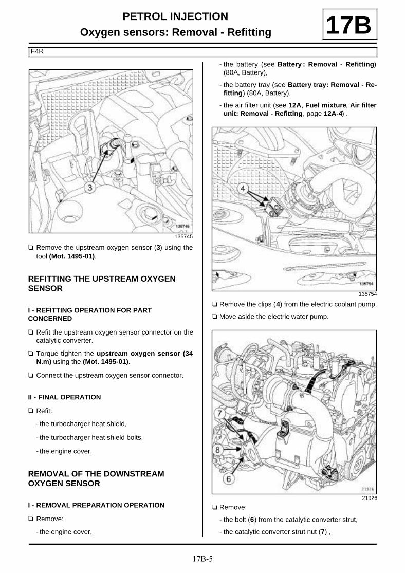
17B-5
PETROL INJECTIONOxygen sensors: Removal - Refitting
F4R
17B
a Remove the upstream oxygen sensor (3) using thetool (Mot. 1495-01).
REFITTING THE UPSTREAM OXYGEN SENSOR
I - REFITTING OPERATION FOR PART CONCERNED
a Refit the upstream oxygen sensor connector on thecatalytic converter.
a Torque tighten the upstream oxygen sensor (34N.m) using the (Mot. 1495-01).
a Connect the upstream oxygen sensor connector.
II - FINAL OPERATION
a Refit:
- the turbocharger heat shield,
- the turbocharger heat shield bolts,
- the engine cover.
REMOVAL OF THE DOWNSTREAM OXYGEN SENSOR
I - REMOVAL PREPARATION OPERATION
a Remove:
- the engine cover,
- the battery (see Battery : Removal - Refitting)(80A, Battery),
- the battery tray (see Battery tray: Removal - Re-fitting) (80A, Battery),
- the air filter unit (see 12A, Fuel mixture, Air filterunit: Removal - Refitting, page 12A-4) .
a Remove the clips (4) from the electric coolant pump.
a Move aside the electric water pump.
a Remove:
- the bolt (6) from the catalytic converter strut,
- the catalytic converter strut nut (7) ,
135745
135754
21926
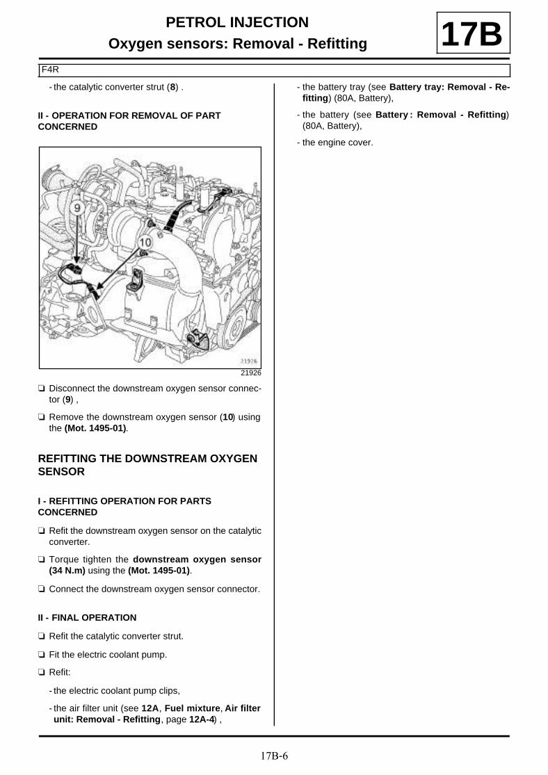
17B-6
PETROL INJECTIONOxygen sensors: Removal - Refitting
F4R
17B- the catalytic converter strut (8) .
II - OPERATION FOR REMOVAL OF PART CONCERNED
a Disconnect the downstream oxygen sensor connec-tor (9) ,
a Remove the downstream oxygen sensor (10) usingthe (Mot. 1495-01).
REFITTING THE DOWNSTREAM OXYGEN SENSOR
I - REFITTING OPERATION FOR PARTS CONCERNED
a Refit the downstream oxygen sensor on the catalyticconverter.
a Torque tighten the downstream oxygen sensor(34 N.m) using the (Mot. 1495-01).
a Connect the downstream oxygen sensor connector.
II - FINAL OPERATION
a Refit the catalytic converter strut.
a Fit the electric coolant pump.
a Refit:
- the electric coolant pump clips,
- the air filter unit (see 12A, Fuel mixture, Air filterunit: Removal - Refitting, page 12A-4) ,
- the battery tray (see Battery tray: Removal - Re-fitting) (80A, Battery),
- the battery (see Battery : Removal - Refitting)(80A, Battery),
- the engine cover.
21926

17B-7
PETROL INJECTIONPetrol injection computer: Removal - Refitting
F4R or K4M
17B
REMOVAL
I - REMOVAL PREPARATION OPERATION
a Apply the procedure before repair using the dia-gnostic tool :
- connect the diagnostic tool,
- select « petrol injection computer » ,
- go to repair mode,
- display the « before repair procedure » on the se-lected computer,
- carry out the operations described in the« procedure before repair » section.
a Disconnect the battery (see Battery: Removal - Re-fitting) (80A, Battery).
a Remove the cover of the petrol injection computer.
a Remove the bolts (1) of the petrol injection computerfrom the battery tray.
II - REMOVAL OPERATION FOR PART CONCERNED
a Move aside the petrol injection computer supportwith the petrol injection computer.
Essential equipment
diagnostic tool
WARNING
Do not use any product designed to improve theelectrical contact in the injection computer and oxy-gen sensor connectors or on the bodies of the oxy-gen sensors.
Failure to respect this advice causes the oxygensensor to malfunction and results in failure to com-ply with the emission control standard.
WARNING
If the connections are corroded, repair the wiring(see Wiring: Precautions for repair) (TechnicalNote 6015A, 88A, Wiring). 136455
136462

17B-8
PETROL INJECTIONPetrol injection computer: Removal - Refitting
F4R or K4M
17B
a Disconnect the connector (2) from the petrol injec-tion computer.
a Remove:
- the « Petrol injection computer - computersupport » assembly,
- the nuts (3) of the petrol injection computer fromthe support,
- the petrol injection computer.
REFITTING
I - REFITTING OPERATION FOR PART CONCERNED
a Refit the petrol injection computer on the support.
a Connect the petrol injection computer connectors.
a Fit the « Petrol injection computer - computersupport » assembly.
a Refit:
- the petrol injection computer on the battery tray,
- the petrol injection computer cover.
II - FINAL OPERATION
a Connect the battery (see Battery: Removal - Refit-ting) (80A, Battery).
a Apply the after repair procedure using the diagnos-tic tool :
- connect the diagnostic tool,
- select « petrol injection computer » ,
- go to repair mode,
- display the « after repair procedure » for the selec-ted computer,
- carry out the operations described in the « after re-pair procedure » section.
136463
134213

17B-9
PETROL INJECTIONPinking sensor: Removal - Refitting
K4M
17B
REMOVAL
I - REMOVAL PREPARATION OPERATION
a Remove the front engine cover.
a Remove:
- the dipstick,
- the bolts (1) from the dipstick tube,
- the dipstick guide.
a Remove:
- the alternator strut bolt (2) from the alternator,
- the alternator strut nut (3) from the cylinder block,
Essential special tooling
Emb. 1797 24 mm socket for removingand refitting clutch mastercylinder
Tightening torquesm
pinking sensor 20 N.m
alternator strut bolt onthe alternator
25 N.m
alternator strut nut onthe cylinder block
25 N.m
alternator strut bolt onthe alternator
25 N.m
alternator strut bolt onthe cylinder block
25 N.m
dipstick guide tube bolts 10 N.m
K4M, and 858 or 866
136574
K4M, and 848
135727

17B-10
PETROL INJECTIONPinking sensor: Removal - Refitting
K4M
17B- the alternator strut.
a Remove:
- the alternator strut bolt (4) from the cylinder block,
- the alternator strut bolt (5) from the alternator,
- the alternator strut.
II - OPERATION FOR REMOVAL OF PART CONCERNED
a Disconnect the pinking sensor connector.
a Remove the pinking sensor (6) using the tool (Emb.1797).
K4M, and 858 or 866
136573
K4M, and 848
135246

17B-11
PETROL INJECTIONPinking sensor: Removal - Refitting
K4M
17B
a Disconnect the pinking sensor connector (7) .
a Remove the pinking sensor using the tool (Emb.1797).
REFITTING
I - REFITTING OPERATION FOR PART CONCERNED
a Refit the pinking sensor.
a Torque tighten the pinking sensor (20 N.m) usingthe tool (Emb. 1797).
a Connect the pinking sensor connector.
II - FINAL OPERATION
a Refit the alternator strut.
a Refit:
- the alternator strut,
- the alternator strut nut on the cylinder block,
- the alternator strut bolt on the alternator.
a Tighten to torque:
- the alternator strut bolt on the alternator (25N.m),
- the alternator strut nut on the cylinder block (25N.m).
a Refit:
- the alternator strut,
- the alternator strut bolt on the cylinder block,
- the alternator strut bolt on the alternator.
a Tighten to torque:
- the alternator strut bolt on the alternator (25N.m),
- the alternator strut bolt on the cylinder block(25 N.m).
a Refit the dipstick guide.
a Torque tighten the dipstick guide tube bolts (10N.m).
a Refit the dipstick.
a Refit the engine cover.
K4M, and 858 or 866
136570
K4M, and 848
K4M, and 858 or 866
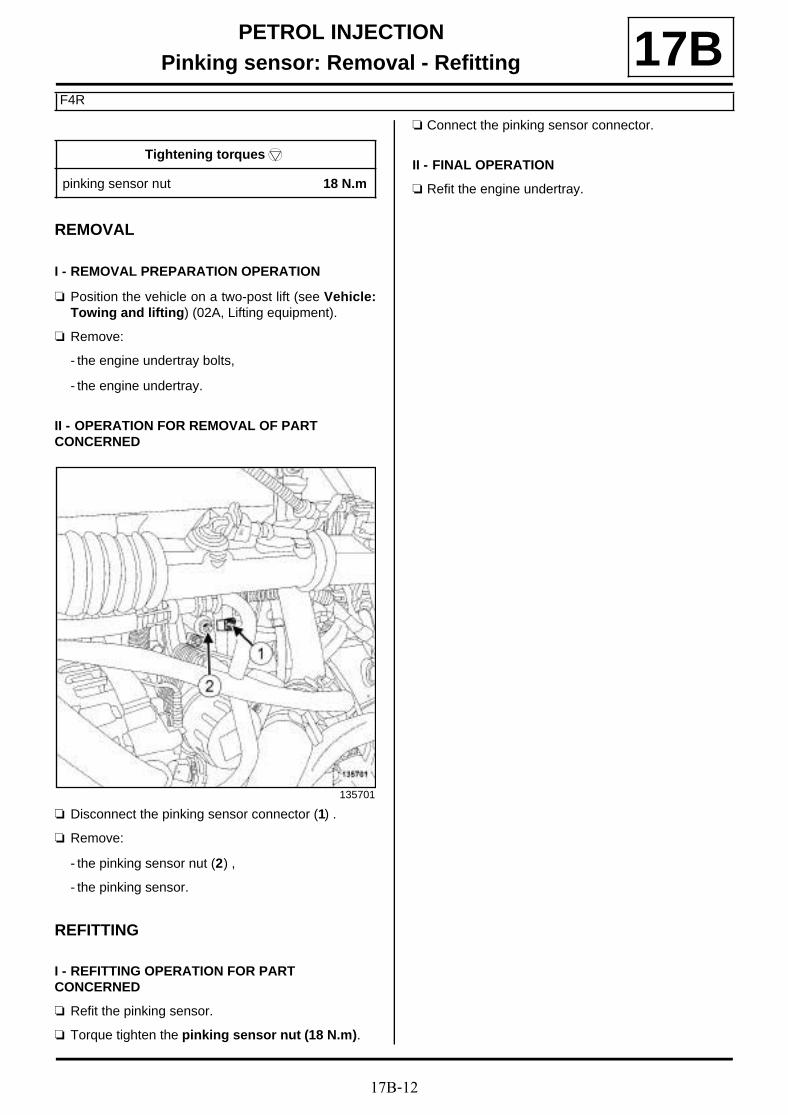
17B-12
PETROL INJECTIONPinking sensor: Removal - Refitting
F4R
17B
REMOVAL
I - REMOVAL PREPARATION OPERATION
a Position the vehicle on a two-post lift (see Vehicle:Towing and lifting) (02A, Lifting equipment).
a Remove:
- the engine undertray bolts,
- the engine undertray.
II - OPERATION FOR REMOVAL OF PART CONCERNED
a Disconnect the pinking sensor connector (1) .
a Remove:
- the pinking sensor nut (2) ,
- the pinking sensor.
REFITTING
I - REFITTING OPERATION FOR PART CONCERNED
a Refit the pinking sensor.
a Torque tighten the pinking sensor nut (18 N.m).
a Connect the pinking sensor connector.
II - FINAL OPERATION
a Refit the engine undertray.
Tightening torquesm
pinking sensor nut 18 N.m
135701

17B-13
PETROL INJECTIONCamshaft position sensor: Removal - Refitting
K4M, and 858 or 866
17B
REMOVAL
I - REMOVAL PREPARATION OPERATION
a Remove:
- the engine cover,
- the windscreen wiper arms (see Windscreen wi-per arm: Removal - Refitting) (85A, Wiping -Washing),
- the scuttle panel grille (see Scuttle panel grille:Removal - Refitting) (56A, Exterior equipment),
- the scoop under the scuttle panel grille (see Scoopunder scuttle panel grille: Removal - Refitting)(56A, Exterior equipment),
- the throttle valve (see 12A, Fuel mixture, Throttlevalve: Removal - Refitting, page 12A-17) ,
- the intake distributor (see 12A, Fuel mixture, Inletmanifold: Removal - Refitting, page 12A-23) .
II - OPERATION FOR REMOVAL OF PART CONCERNED
a Disconnect the connector (1) from the camshaft po-sition sensor.
a Remove:
- the bolt (2) from the camshaft position sensor,
- the camshaft position sensor.
REFITTING
I - REFITTING OPERATION FOR PART CONCERNED
a Refit the camshaft position sensor.
a Torque tighten the camshaft position sensor bolt(8 Nm).
a Connect the camshaft position sensor connector.
II - FINAL OPERATION
a Refit:
- the inlet manifold (see 12A, Fuel mixture, Inletmanifold: Removal - Refitting, page 12A-23) ,
- the throttle valve (see 12A, Fuel mixture, Throttlevalve: Removal - Refitting, page 12A-17) ,
- the scoop under the scuttle panel grille (see Scoopunder scuttle panel grille: Removal - Refitting)(56A, Exterior equipment),
- the scuttle panel grille (see Scuttle panel grille:Removal - Refitting) (56A, Exterior equipment),
- the windscreen wiper arms (see Windscreen wi-per arm: Removal - Refitting) (85A, Wiping -Washing),
- the engine cover.
Tightening torquesm
camshaft position sen-sor bolt
8 Nm
136585
136586

17B-14
PETROL INJECTIONCamshaft position sensor: Removal - Refitting
F4R
17BREMOVAL
I - REMOVAL PREPARATION OPERATION
a Remove the front engine cover.
II - OPERATION FOR REMOVAL OF PART CONCERNED
a Disconnect the connector (1) from the camshaft po-sition sensor.
a Remove:
- the bolt (2) from the camshaft position sensor,
- the camshaft position sensor.
REFITTING
I - REFITTING OPERATION FOR PART CONCERNED
a Refit the camshaft position sensor.
a Connect the camshaft position sensor connector.
II - FINAL OPERATION
a Refit the engine cover.
135748
135747
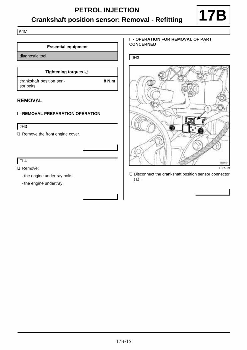
17B-15
PETROL INJECTIONCrankshaft position sensor: Removal - Refitting
K4M
17B
REMOVAL
I - REMOVAL PREPARATION OPERATION
a Remove the front engine cover.
a Remove:
- the engine undertray bolts,
- the engine undertray.
II - OPERATION FOR REMOVAL OF PART CONCERNED
a Disconnect the crankshaft position sensor connector(1) .
Essential equipment
diagnostic tool
Tightening torquesm
crankshaft position sen-sor bolts
8 N.m
JH3
TL4
JH3
135919

17B-16
PETROL INJECTIONCrankshaft position sensor: Removal - Refitting
K4M
17B
a Disconnect the crankshaft position sensor connector(2) .
a Remove:
- the crankshaft position sensor bolts (3) ,
- the crankshaft position sensor.
a Remove:
- the crankshaft position sensor bolt (4) ,
- the crankshaft position sensor.
REFITTING
I - REFITTING OPERATION FOR PART CONCERNED
a Refit the crankshaft position sensor.
a Torque tighten the crankshaft position sensorbolts (8 N.m).
a Connect the crankshaft position sensor connector.
TL4
136549
JH3
135919
TL4
136549
JH3

17B-17
PETROL INJECTIONCrankshaft position sensor: Removal - Refitting
K4M
17BII - FINAL OPERATION
a Refit the engine undertray.
a Refit the engine cover.
a Apply the after repair procedure using the diagnos-tic tool :
- Connect the diagnostic tool,
- select « injection computer » ,
- go to repair mode,
- display the « Before/After repair procedure » forthe computer selected,
- select « TDC sensor » in the « List of componentscontrolled by this computer » section,
- carry out the operations described in the « After re-pair procedure » section.
TL4
JH3

17B-18
PETROL INJECTIONCrankshaft position sensor: Removal - Refitting
F4R
17BREMOVAL
I - REMOVAL PREPARATION OPERATION
a Position the vehicle on a two-post lift (see Vehicle:Towing and lifting) (02A, Lifting equipment).
a Remove:
- the engine undertray bolts,
- the engine undertray.
II - OPERATION FOR REMOVAL OF PART CONCERNED
a Disconnect the crankshaft position sensor connector(1) .
a Remove:
- the crankshaft position sensor bolt (2) ,
- the crankshaft position sensor.
REFITTING
REFITTING OPERATION FOR PART CONCERNED
a Refit the crankshaft position sensor.
a Tighten the crankshaft position sensor bolt.
a Connect the crankshaft position sensor connector.
FINAL OPERATION
a Refit the engine undertray.
102485

17B-19
PETROL INJECTIONInjector rail - Injectors: Removal - Refitting
K4M
17B
REMOVAL
I - REMOVAL PREPARATION OPERATION
a Disconnect the battery (see Battery: Removal - Re-fitting) (80A, Battery).
a Remove:
- the engine cover,
- the windscreen wiper arms (see Windscreen wi-per arm: Removal - Refitting) (85A, Wiping -Washing),
- the scuttle panel grille (see Scuttle panel grille:Removal - Refitting) (56A, Exterior equipment),
- the scoop under the scuttle panel grille (see Scoopunder scuttle panel grille: Removal - Refitting)(56A, Exterior equipment),
- the throttle valve (see 12A, Fuel mixture, Throttlevalve: Removal - Refitting, page 12A-17) ,
- the intake distributor (see 12A, Fuel mixture, Inletmanifold: Removal - Refitting, page 12A-23) .
II - OPERATION FOR REMOVAL OF PART CONCERNED
a
a Remove:
- the « injector rail - injector » assembly bolts (1) ,
- the « injector rail - injector » assembly.
a Unclip the injector wiring from the « injector rail -injector » assembly.
a Disconnect:
- all injector connectors,
- the fuel supply pipe union from the injector rail.
a Fit blanking plugs.
Essential equipment
diagnostic tool
Tightening torquesm
bolts of the « injector rail- injector » assembly
10 N.m
IMPORTANT
Wear leaktight gloves (Nitrile type) for this opera-tion.
IMPORTANT
During this operation, be sure to:
- refrain from smoking or bringing red hot objectsclose to the working area,
- be careful of fuel splashes when disconnecting theunion.
IMPORTANT
Be careful when removing the injectors or the injec-tion rail as there will be a quantity of fuel in the railand the union.
WARNINGTo avoid any corrosion or damage, protect theareas on which fuel is likely to run.
134582

17B-20
PETROL INJECTIONInjector rail - Injectors: Removal - Refitting
K4M
17B
a Remove:
- the clip (2) from each injector,
- the injectors (3) from the injector rail,
- the seals of each injector.
a Insert the blanking plugs.
REFITTING
I - REFITTING PREPARATION OPERATION
a parts always to be replaced: injector clip on in-jector rail (11,04,04,10).
a parts always to be replaced: injector seal (11,11,02,02).
a Refit:
- new seals on each injector,
- the injectors on the injector rail,
- a new clip on each injector.
II - REFITTING OPERATION FOR PART CONCERNED
a Remove the blanking plugs.
a Connect:
- the supply pipe union on the injector rail,
- all injector connectors.
a Clip the injector wiring onto the « injector rail -injector » assembly.
a Refit the « injector rail - injector » assembly.
a Torque tighten the bolts of the « injector rail -injector » assembly (10 N.m).
III - FINAL OPERATION
a Refit:
- the inlet manifold (see 12A, Fuel mixture, Inletmanifold: Removal - Refitting, page 12A-23) ,
- the throttle valve (see 12A, Fuel mixture, Throttlevalve: Removal - Refitting, page 12A-17) ,
- the scoop under the scuttle panel grille (see Scoopunder scuttle panel grille: Removal - Refitting)(56A, Exterior equipment),
- the scuttle panel grille (see Scuttle panel grille:Removal - Refitting) (56A, Exterior equipment),
- the windscreen wiper arms (see Windscreen wi-per arm: Removal - Refitting) (85A, Wiping -Washing),
- the engine cover.
a Connect the battery (see Battery: Removal - Refit-ting) (80A, Battery).
a Apply the after repair procedure using the diagnos-tic tool :
- Connect the diagnostic tool,
- select « injection computer » ,
- go to repair mode,
- display the « before/after repair procedure » for thecomputer selected,
- select « Injector no. 1 » in the « List of componentscontrolled by this computer » section,
- carry out the operations described in the « After re-pair procedure » section.
101492

17B-21
PETROL INJECTIONInjector rail - Injectors: Removal - Refitting
F4R
17B
REMOVAL
I - REMOVAL PREPARATION OPERATION
a Disconnect the battery (see Battery : Removal -Refitting) (80A, Battery).
a Remove the front engine cover.
a Disconnect the connectors (1) from the oil vapour re-breathing pipe.
a Remove the oil vapour rebreathing pipe.
a Disconnect the injector connectors (2) .
Tightening torquesm
injector rail bolts 10 N.m
IMPORTANT
During this operation, be sure to:
- refrain from smoking or bringing red hot objectsclose to the working area,
- be careful of fuel splashes when disconnecting theunion.
IMPORTANT
Wear leaktight gloves (Nitrile type) for this opera-tion.
IMPORTANT
Wear goggles with side protectors for this opera-tion.
135744
134642

17B-22
PETROL INJECTIONInjector rail - Injectors: Removal - Refitting
F4R
17B
a Disconnect:
- the fuel supply pipe (3) on the injector rail,
- the petrol vapour rebreathing pipe (4) .
a Remove the petrol vapour rebreathing pipe.
II - OPERATION FOR REMOVAL OF PART CONCERNED
a
Remove:
- the bolts (5) of the injector rail - injector assembly,
- the injector rail - injector assembly.
a Remove:
- the clip (6) from each injector,
- the injectors (7) .
REFITTING
I - REFITTING PREPARATION OPERATION
a Always replace the injector seals.
a Refit:
- new injector seals,
- the injectors.
II - REFITTING OPERATION FOR PART CONCERNED
a Refit the injector rail.
a Torque tighten the injector rail bolts (10 N.m).
III - FINAL OPERATION
a Refit the petrol vapour rebreathing pipe.
a Connect:
- the fuel supply pipe to the injector rail,
- the injector connectors.
a Refit:
- the oil vapour rebreathing pipe,
- the engine cover.
135779
123735
IMPORTANT
Be careful when removing the injectors or theinjection rail as there will be a quantity of fuel inthe rail and the union.
135781

17B-23
PETROL INJECTIONInjector rail - Injectors: Removal - Refitting
F4R
17Ba Connect the battery.

19A-1
COOLINGEngine cooling circuit: Specifications 19A
Vehicles in the current range have cooling systems with the following basic specifications:
- hermetically-sealed pressurised circuit (expansionchamber valve),
- circuit using a “D” type coolant,
- passenger compartment heating systems equippedwith a "heater matrix" type radiator located under thedashboard which helps to cool the engine.
Volume of coolant
Special notes:
- protection down to -25˚C ±±±± 2 for cold and temperatecountries,
- protection down to -37˚C ±±±± 2 for very cold countries.
thermostat
Engine Quantity(litres)
Grade
K4M 848 5.3 l
GLACEROL RX(type D)
Only use coolant
K4M 858 5.3 l
K4M 866 5.3 l
F4R 870 6.5 l
K9K 830 6.5 l
K9K832 6.5 l
K9K 834 6.5 l
F9Q 870 6.3 l
F9Q 872 6.3 l
Engine Start of ope-ning (˚C)
End of opening(˚C)
K4M 848 89 99 ±±±± 2
K4M 858 89 99 ±±±± 2
K4M 866 89 99 ±±±± 2
F4R 870 83 95
K9K 830 83 95
K9K832 83 95
K9K 834 83 95
F9Q 870 83 95
F9Q 872 83 95
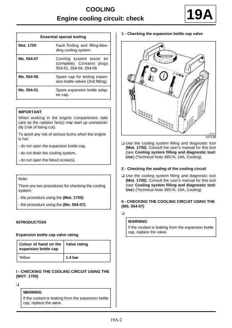
19A-2
COOLINGEngine cooling circuit: check 19A
INTRODUCTION
Expansion bottle cap valve rating
I - CHECKING THE COOLING CIRCUIT USING THE (MOT. 1700)
a
1 - Checking the expansion bottle cap valve
a Use the cooling system filling and diagnostic tool(Mot. 1700). Consult the user's manual for this tool(see Cooling system filling and diagnostic tool:Use) (Technical Note 3857A, 19A, Cooling).
2 - Checking the sealing of the cooling circuit
a Use the cooling system filling and diagnostic tool(Mot. 1700). Consult the user's manual for this tool(see Cooling system filling and diagnostic tool:Use) (Technical Note 3857A, 19A, Cooling).
II - CHECKING THE COOLING CIRCUIT USING THE (MS. 554-07)
a
Essential special tooling
Mot. 1700 Fault finding and filling-blee-ding cooling system.
Ms. 554-07 Cooling system tester kit(complete). Contains plugs554-01, 554-04, 554-06
Ms. 554-06 Spare cap for testing expan-sion bottle valves (2nd fitting).
Ms. 554-01 Spare expansion bottle adap-ter cap.
IMPORTANT
When working in the engine compartment, takecare as the radiator fan(s) may start up unexpecte-dly (risk of being cut).
To avoid any risk of serious burns when the engine is hot:
- do not open the expansion bottle cap,
- do not drain the cooling system,
- do not open the bleed screw(s).
Note:
There are two procedures for checking the cooling system:
- the procedure using the (Mot. 1700)
- the procedure using the (Ms. 554-07).
Colour of hand on theexpansion bottle cap
Valve rating
Yellow 1.4 bar
WARNING
If the coolant is leaking from the expansion bottlecap, replace the valve.
107138
WARNING
If the coolant is leaking from the expansion bottlecap, replace the valve.

19A-3
COOLINGEngine cooling circuit: check 19A
1 - Checking the expansion bottle cap valve
a Fit the test tool (Ms. 554-07) with an adapter (Ms.554-06).
a Fit the expansion bottle cap onto the adapter (Ms.554-06).
a Pump with the (Ms. 554-07), the pressure shouldstabilise at the expansion bottle cap valve rating witha test tolerance of ± 0.1 bar.
2 - Checking the sealing of the cooling circuit
a Replace the expansion bottle cap with the adapter(Ms. 554-01).
a Connect the adapter (Ms. 554-01) to the (Ms. 554-07).
a Use the tool as a pump to pressurise the coolingsystem.
a Stop pumping at 0.1 bar below the valve rating forthe expansion bottle cap valve.
a Gradually undo the union of the (Ms. 554-07) to de-compress the cooling system and then remove theadapter (Ms. 554-01) and refit the expansion bottlecap.
97871
Note:
The pressure should not drop; if it does, look forthe leak.
Note:
The pressure should not drop; if it does, look forthe leak.
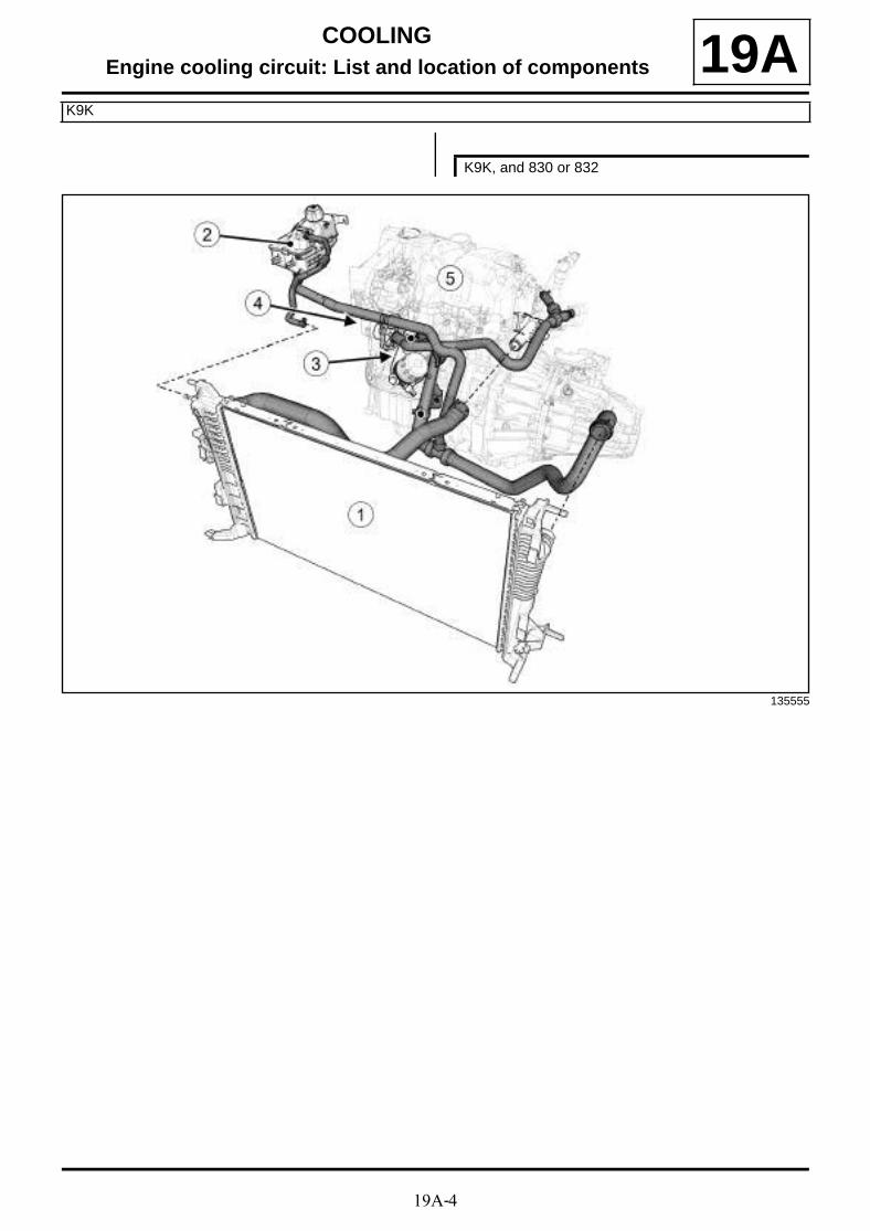
19A-4
COOLINGEngine cooling circuit: List and location of components
K9K
19A
K9K, and 830 or 832
135555

19A-5
COOLINGEngine cooling circuit: List and location of components
K9K
19A
135558

19A-6
COOLINGEngine cooling circuit: List and location of components
K9K
19A
135560
(1) Cooling radiator
(2) Expansion bottle
(3) Water-oil heat exchanger
(4) Water pump
(5) Engine
(6) Thermostat
(7) Coolant outlet unit
(8) Drain plug
(9) Bleed screws

19A-7
COOLINGEngine cooling circuit: List and location of components
K9K
19A
K9K, and 834
135561

19A-8
COOLINGEngine cooling circuit: List and location of components
K9K
19A
135564

19A-9
COOLINGEngine cooling circuit: List and location of components
K9K
19A
135566
(1) Cooling radiator
(2) Expansion bottle
(3) Water-oil heat exchanger
(4) Water pump
(5) Engine
(6) Thermostat
(7) Coolant outlet unit
(8) Drain plug
(9) Bleed screws
(10) Thermoplunger unit
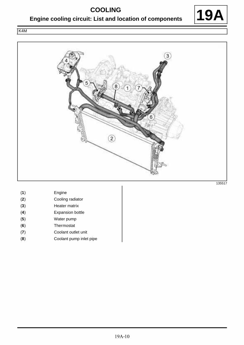
19A-10
COOLINGEngine cooling circuit: List and location of components
K4M
19A
135517
(1) Engine
(2) Cooling radiator
(3) Heater matrix
(4) Expansion bottle
(5) Water pump
(6) Thermostat
(7) Coolant outlet unit
(8) Coolant pump inlet pipe
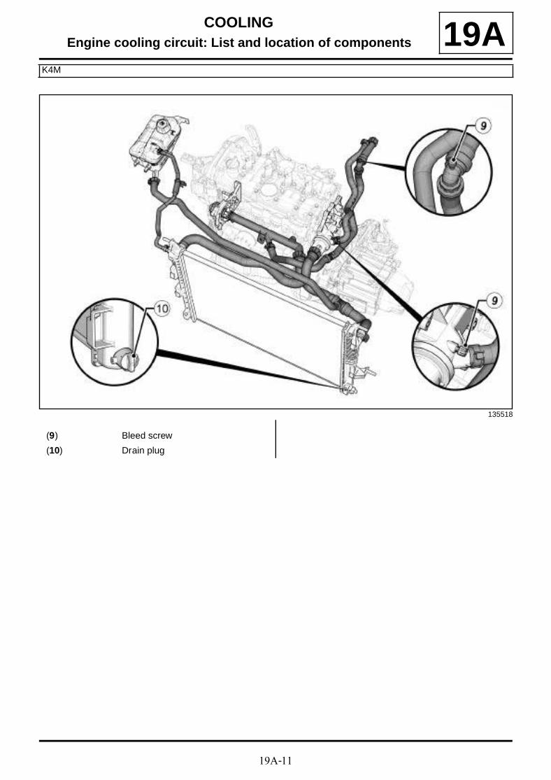
19A-11
COOLINGEngine cooling circuit: List and location of components
K4M
19A
135518
(9) Bleed screw
(10) Drain plug

19A-12
COOLINGEngine cooling circuit: List and location of components
F4R
19A
135611
(1) Turbocharger
(2) Electric coolant pump
(3) Coolant outlet unit

19A-13
COOLINGEngine cooling circuit: List and location of components
F4R
19A
135612
(4) Expansion bottle
(5) Water pump
(6) Radiator
(7) Thermostat

19A-14
COOLINGEngine cooling circuit: List and location of components
F4R
19A
135613
(8) Bleed screw
(9) Drain plug
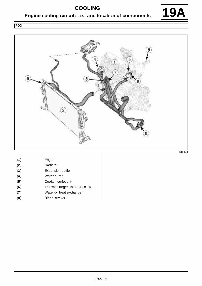
19A-15
COOLINGEngine cooling circuit: List and location of components
F9Q
19A
135424
(1) Engine
(2) Radiator
(3) Expansion bottle
(4) Water pump
(5) Coolant outlet unit
(6) Thermoplunger unit (F9Q 870)
(7) Water-oil heat exchanger
(8) Bleed screws

19A-16
COOLINGEngine cooling circuit: List and location of components
F9Q
19A
135423
(9) Intercooler
(10) Exhaust fuel injector cooler(F9Q 870)
(11) Heater matrix

19A-17
COOLINGCooling circuit: Draining - Refilling
K4M
19A
DRAINING
a Position the vehicle on a two-post lift (see Vehicle:Towing and lifting) (02A, Lifting equipment).
a Remove:
- the engine cover,
- the expansion bottle cap,
- the front wheels (see Wheel: Removal - Refitting)(35A, Wheels and tyres),
- the front section of the front wheel arch liners (seeFront wheel arch liner: Removal - Refitting)(55A, Exterior protection),
- the engine undertray bolts,
- the engine undertray.
- the front bumper (see Front bumper: Removal -Refitting) (55A, Exterior protection),
a Position the coolant draining tray under the vehi-cle.
a Open the drain plug (1) for the radiator cooling sys-tem.
a Use a compressed air nozzle to blow air into thesystem through the expansion bottle opening to re-move as much coolant as possible.
CLEANING
a Fill the cooling system with water through the expan-sion bottle.
a Let the water run until the water collected by the coo-ling radiator bottom hose becomes clear.
a Use a compressed air nozzle to blow air into thecircuit through the expansion bottle opening to re-move as much water as possible.
a Close the drain plug of the radiator cooling system.
Essential special tooling
Mot. 1700 Fault finding and filling-blee-ding cooling system.
Ms. 554-07 Cooling system tester kit(complete). Contains plugs554-01, 554-04, 554-06
Essential equipment
coolant draining tray
compressed air nozzle
pedal press
IMPORTANT
When working in the engine compartment, takecare as the radiator fan(s) may start up unexpecte-dly (risk of being cut).
To avoid any risk of serious burns when the engine is hot:
- do not open the expansion bottle cap,
- do not drain the cooling system,
- do not open the bleed screw(s).
WARNING
Before the operation, protect the electrical accesso-ries to prevent any risk of shor t circuiting and pro-tect the belts to avoid damaging them.
136540

19A-18
COOLINGCooling circuit: Draining - Refilling
K4M
19AFILLING
a
1 - Filling procedure with the tool (Mot. 1700)
a Fill the cooling system with engine coolant recom-mended by the manufacturer (see Vehicle: Partsand ingredients for the repairwork) (04B, Consu-
mables - Products) using the tool (Mot. 1700). Con-sult the user's manual for this tool (see Coolingsystem filling and diagnostic tool: Use) (Techni-cal Note 3857A, 19A, Cooling).
2 - Filling procedure without a special tool
a
Method to access the bleed screws on the heater matrix hose and on the coolant outlet unit
a Remove:
- the bleed screw (2) of the coolant outlet unit,
- the bleed screw (3) of the heater matrix hose.
a Fill the cooling system with engine coolant recom-mended by the manufacturer (see 19A, Cooling,Engine cooling circuit: Specifications, page 19A-
Note:
There are two procedures for filling the cooling system:
- the procedure using the tool (Mot. 1700)recommended by Renault. It saves a considera-ble amount of time because it does not requirethe cooling system bleed screws to be opened,
- the procedure without a special tool.
WARNING
It is essential to open all of the bleed screws toremove as much as air as possible in the coolingsystem. Failure to perform this procedure mayprevent the cooling system from filling properlyand may damage the engine.
135518

19A-19
COOLINGCooling circuit: Draining - Refilling
K4M
19A1) and (see Vehicle: Parts and ingredients for therepairwork) (04B, Consumables - Products) via theexpansion bottle until it overflows.
a Close all the bleed screws as soon as the coolantstarts to flow in a continuous stream.
a Pressurise the system using the (Ms. 554-07) tocheck that there are no leaks (see 19A, Cooling,Engine cooling circuit: check, page 19A-2) .
a Fill the expansion bottle until it overflows.
a Tighten the expansion bottle cap.
a Clean any surfaces soiled by the coolant.
BLEEDING
a
a Deactivate the air conditioning system so that thefan assembly is not operating from the start of theoperation.
a Start the engine.
a Maintain the engine speed at 2500 rpm using a pe-dal press, until the fan assembly starts for the se-cond time.
a Check that the heating is operating correctly.
a Allow the engine to cool until the coolant temperatu-re is less than 50˚C.
a Make sure the coolant fluid level is at the« Maximum » mark.
a Refit the expansion bottle cap.
FINAL OPERATION
a Remove the coolant draining tray.
a Refit:
- the front bumper (see Front bumper: Removal -Refitting) (55A, Exterior protection),
- the front section of the front wheel arch liners (seeFront wheel arch liner: Removal - Refitting)(55A, Exterior protection),
- the front wheels (see Wheel: Removal - Refitting)(35A, Wheels and tyres),
- the engine undertray,
- the engine cover.
WARNING
Do not open the bleed screw whilst the engine isrunning; this would damage the engine.

19A-20
COOLINGCooling circuit: Draining - Refilling
K9K
19A
DRAINING
a Position the vehicle on a two-post lift (see Vehicle:Towing and lifting) (02A, Lifting equipment).
a Remove:
- the engine cover,
- the expansion bottle cap,
- the front wheels (see Wheel: Removal - Refitting)(35A, Wheels and tyres),
- the front sections of the front wheel arch liners (seeFront wheel arch liner: Removal - Refitting)(55A, Exterior protection),
- the engine undertray bolts,
- the engine undertray.
- the front bumper (see Front bumper: Removal -Refitting) (55A, Exterior protection),
a Position the coolant draining tray under the vehi-cle.
a Open the drain plug (1) for the radiator cooling sys-tem.
a Use a compressed air nozzle to blow air into thesystem through the expansion bottle opening to re-move as much coolant as possible.
CLEANING
a Fill the cooling system with water through the expan-sion bottle.
a Let the water run until the water collected by the coo-ling radiator bottom hose becomes clear.
a Use a compressed air nozzle to blow air into thecircuit through the expansion bottle opening to re-move as much water as possible.
a Close the drain plug of the radiator cooling system.
Essential special tooling
Mot. 1700 Fault finding and filling-blee-ding cooling system.
Ms. 554-07 Cooling system tester kit(complete). Contains plugs554-01, 554-04, 554-06
Essential equipment
coolant draining tray
compressed air nozzle
IMPORTANTWhen working in the engine compartment, takecare as the radiator fan(s) may start up unexpecte-dly (risk of being cut).
To avoid any risk of serious burns when the engine is hot:
- do not open the expansion bottle cap,
- do not drain the cooling system,
- do not open the bleed screw(s).
WARNING
Before the operation, protect the electrical accesso-ries to prevent any risk of shor t circuiting and pro-tect the belts to avoid damaging them.
136540

19A-21
COOLINGCooling circuit: Draining - Refilling
K9K
19AFILLING
a
1 - Filling procedure with the tool (Mot. 1700)
a Fill the cooling system with engine coolant recom-mended by the manufacturer (see Vehicle: Partsand ingredients for the repairwork) (04B, Consu-
mables - Products) using the tool (Mot. 1700). Con-sult the user's manual for this tool (see Coolingsystem filling and diagnostic tool: Use) (Techni-cal Note 3857A, 19A, Cooling).
2 - Filling procedure without a special tool
a
Method to access the bleed screws on the heater matrix hose and on the coolant outlet unit
a Remove:
- the bleed screw (2) of the coolant outlet unit,
- the bleed screw (3) of the heater matrix hose.
Note:
There are two procedures for filling the cooling system:
- the procedure using the tool (Mot. 1700)recommended by Renault. It saves a considera-ble amount of time because it does not requirethe cooling system bleed screws to be opened,
- the procedure without a special tool.
WARNING
It is essential to open all of the bleed screws toremove as much as air as possible in the coolingsystem. Failure to perform this procedure mayprevent the cooling system from filling properlyand may damage the engine.
K9K, and 830 or 832
135560

19A-22
COOLINGCooling circuit: Draining - Refilling
K9K
19A
a Remove:
- the bleed screw (4) of the coolant outlet unit,
- the bleed screw (5) of the heater matrix hose.
a Fill the cooling system with engine coolant recom-mended by the manufacturer (see 19A, Cooling,Engine cooling circuit: Specifications, page 19A-1) and (see Vehicle: Parts and ingredients for therepairwork) (04B, Consumables - Products) via theexpansion bottle until it overflows.
a Close all the bleed screws as soon as the coolantstarts to flow in a continuous stream.
a Pressurise the system using the (Ms. 554-07) tocheck that there are no leaks (see 19A, Cooling,Engine cooling circuit: check, page 19A-2) .
a Fill the expansion bottle until it overflows.
a Tighten the expansion bottle cap.
a Clean any surfaces soiled by the coolant.
BLEEDING
a
a Deactivate the air conditioning system so that thefan assembly is not operating from the start of theoperation.
a Start the engine.
a Maintain the engine speed at 1500 rpm, sharply va-rying the engine speed (up to the maximum) 2 to 3times approximately every 2 minutes until the fanassembly starts for the second time.
a Check that the heating is operating correctly.
a Allow the engine to cool until the coolant temperatu-re is less than 50˚C.
a Make sure the coolant fluid level is at the« Maximum » mark.
a Refit the expansion bottle cap.
K9K, and 834
135566
WARNING
Do not open the bleed screw whilst the engine isrunning; this would damage the engine.
19A-23
COOLINGCooling circuit: Draining - Refilling
K9K
19AFINAL OPERATION
a Remove the coolant draining tray.
a Refit:
- the front bumper (see Front bumper: Removal -Refitting) (55A, Exterior protection),
- the front sections of the front wheel arch liners (seeFront wheel arch liner: Removal - Refitting)(55A, Exterior protection),
- the front wheels (see Wheel: Removal - Refitting)(35A, Wheels and tyres),
- the engine undertray,
- the engine cover.

19A-24
COOLINGCooling circuit: Draining - Refilling
F4R
19A
DRAINING
a Position the vehicle on a two-post lift (see Vehicle:Towing and lifting) (02A, Lifting equipment).
a Remove:
- the engine cover,
- the expansion bottle cap,
- the front wheels (see Wheel: Removal - Refitting)(35A, Wheels and tyres),
- the front section of the front wheel arch liners (seeFront wheel arch liner: Removal - Refitting)(55A, Exterior protection),
- the engine undertray bolts,
- the engine undertray,
- the front bumper (see Front bumper: Removal -Refitting) (55A, Exterior protection).
a Position the coolant draining tray under the vehi-cle.
a Open the drain plug (1) for the radiator cooling sys-tem.
a Use a compressed air nozzle to blow air into thesystem through the expansion bottle opening to re-move as much coolant as possible.
CLEANING
a Fill the cooling system with water through the expan-sion bottle.
a Let the water run until the water collected by the coo-ling radiator bottom hose becomes clear.
a Use a compressed air nozzle to blow air into thecircuit through the expansion bottle opening to re-move as much water as possible.
a Close the drain plug of the radiator cooling system.
Essential special tooling
Mot. 1700 Fault finding and filling-blee-ding cooling system.
Ms. 554-07 Cooling system tester kit(complete). Contains plugs554-01, 554-04, 554-06
Essential equipment
coolant draining tray
compressed air nozzle
pedal press
IMPORTANT
When working in the engine compartment, takecare as the radiator fan(s) may start up unexpecte-dly (risk of being cut).
To avoid any risk of serious burns when the engine is hot:
- do not open the expansion bottle cap,
- do not drain the cooling system,
- do not open the bleed screw(s).
WARNING
Before the operation, protect the electrical accesso-ries to prevent any risk of shor t circuiting and pro-tect the belts to avoid damaging them.
136540

19A-25
COOLINGCooling circuit: Draining - Refilling
F4R
19AFILLING
a
1 - Filling procedure with the tool (Mot. 1700)
a Fill the cooling system with engine coolant recom-mended by the manufacturer (see Vehicle: Partsand ingredients for the repairwork) (04B, Consu-
mables - Products) using the tool (Mot. 1700). Con-sult the user's manual for this tool (see Coolingsystem filling and diagnostic tool: Use) (Techni-cal Note 3857A, 19A, Cooling).
2 - Filling procedure without a special tool
a
Method to access the bleed screws on the heater matrix hose and on the coolant outlet unit
a Remove:
- the bleed screw (2) of the coolant outlet unit,
- the bleed screw (3) of the heater matrix hose.
a Fill the cooling system with engine coolant recom-mended by the manufacturer (see 19A, Cooling,Engine cooling circuit: Specifications, page 19A-
Note:
There are two procedures for filling the cooling system:
- the procedure using the tool (Mot. 1700)recommended by Renault. It saves a considera-ble amount of time because it does not requirethe cooling system bleed screws to be opened,
- the procedure without a special tool.
WARNING
It is essential to open all of the bleed screws toremove as much as air as possible in the coolingsystem. Failure to perform this procedure mayprevent the cooling system from filling properlyand may damage the engine.
135613

19A-26
COOLINGCooling circuit: Draining - Refilling
F4R
19A1) and (see Vehicle: Parts and ingredients for therepairwork) (04B, Consumables - Products) via theexpansion bottle until it overflows.
a Close all the bleed screws as soon as the coolantstarts to flow in a continuous stream.
a Pressurise the system using the (Ms. 554-07) tocheck that there are no leaks (see 19A, Cooling,Engine cooling circuit: check, page 19A-2) .
a Fill the expansion bottle until it overflows.
a Tighten the expansion bottle cap.
a Clean any surfaces soiled by the coolant.
BLEEDING
a Deactivate the air conditioning system so that thefan assembly is not operating from the start of theoperation.
a Start the engine.
a Maintain the engine speed at 2500 rpm using a pe-dal press, until the fan assembly starts for the se-cond time.
a Check that the heating is operating correctly.
a Allow the engine to cool until the coolant temperatu-re is less than 50˚C.
a Make sure the coolant fluid level is at the« Maximum » mark.
a Refit the expansion bottle cap.
FINAL OPERATION
a Remove the coolant draining tray.
a Refit:
- the front bumper (see Front bumper: Removal -Refitting) (55A, Exterior protection),
- the front section of the front wheel arch liners (seeFront wheel arch liner: Removal - Refitting)(55A, Exterior protection),
- the front wheels (see Wheel: Removal - Refitting)(35A, Wheels and tyres),
- the engine undertray,
- the expansion bottle cap,
- the engine cover.
WARNING
Do not open the bleed screw whilst the engine isrunning; this would damage the engine.
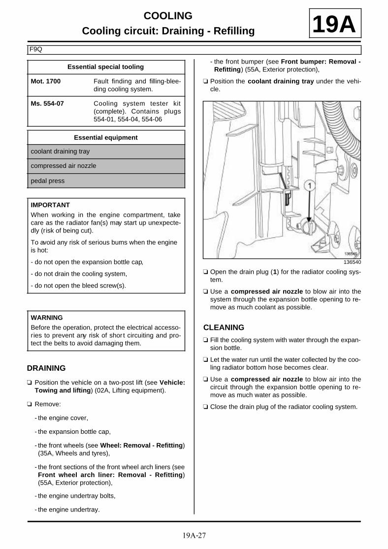
19A-27
COOLINGCooling circuit: Draining - Refilling
F9Q
19A
DRAINING
a Position the vehicle on a two-post lift (see Vehicle:Towing and lifting) (02A, Lifting equipment).
a Remove:
- the engine cover,
- the expansion bottle cap,
- the front wheels (see Wheel: Removal - Refitting)(35A, Wheels and tyres),
- the front sections of the front wheel arch liners (seeFront wheel arch liner: Removal - Refitting)(55A, Exterior protection),
- the engine undertray bolts,
- the engine undertray.
- the front bumper (see Front bumper: Removal -Refitting) (55A, Exterior protection),
a Position the coolant draining tray under the vehi-cle.
a Open the drain plug (1) for the radiator cooling sys-tem.
a Use a compressed air nozzle to blow air into thesystem through the expansion bottle opening to re-move as much coolant as possible.
CLEANING
a Fill the cooling system with water through the expan-sion bottle.
a Let the water run until the water collected by the coo-ling radiator bottom hose becomes clear.
a Use a compressed air nozzle to blow air into thecircuit through the expansion bottle opening to re-move as much water as possible.
a Close the drain plug of the radiator cooling system.
Essential special tooling
Mot. 1700 Fault finding and filling-blee-ding cooling system.
Ms. 554-07 Cooling system tester kit(complete). Contains plugs554-01, 554-04, 554-06
Essential equipment
coolant draining tray
compressed air nozzle
pedal press
IMPORTANT
When working in the engine compartment, takecare as the radiator fan(s) may start up unexpecte-dly (risk of being cut).
To avoid any risk of serious burns when the engine is hot:
- do not open the expansion bottle cap,
- do not drain the cooling system,
- do not open the bleed screw(s).
WARNING
Before the operation, protect the electrical accesso-ries to prevent any risk of shor t circuiting and pro-tect the belts to avoid damaging them.
136540

19A-28
COOLINGCooling circuit: Draining - Refilling
F9Q
19AFILLING
a
1 - Filling procedure with the tool (Mot. 1700)
a Fill the cooling system with engine coolant recom-mended by the manufacturer (see Vehicle: Partsand ingredients for the repairwork) (04B, Consu-
mables - Products) using the tool (Mot. 1700). Con-sult the user's manual for this tool (see Coolingsystem filling and diagnostic tool: Use) (Techni-cal Note 3857A, 19A, Cooling).
2 - Filling procedure without a special tool
a
Method to access the bleed screws on the heater matrix hose and on the coolant outlet unit
a Remove:
- the battery (see Battery: Removal - Refitting)(80A, Battery),
- the battery tray (see Battery tray: Removal - Re-fitting) (80A, Battery),
- the bleed screw (2) of the coolant outlet unit,
Note:
There are two procedures for filling the cooling system:
- the procedure using the tool (Mot. 1700)recommended by Renault. It saves a considera-ble amount of time because it does not requirethe cooling system bleed screws to be opened,
- the procedure without a special tool.
WARNING
It is essential to open all of the bleed screws toremove as much as air as possible in the coolingsystem. Failure to perform this procedure mayprevent the cooling system from filling properlyand may damage the engine.
135426

19A-29
COOLINGCooling circuit: Draining - Refilling
F9Q
19A- the bleed screw (3) of the heater matrix hose,
- the bleed screw (4) of the cooling radiator bottomhose,
- the bleed screw (5) of the cooling radiator.
a Fill the cooling system with engine coolant recom-mended by the manufacturer (see 19A, Cooling,Engine cooling circuit: Specifications, page 19A-1) and (see Vehicle: Parts and ingredients for therepairwork) (04B, Consumables - Products) via theexpansion bottle until it overflows.
a Close all the bleed screws as soon as the coolantstarts to flow in a continuous stream.
a Refit:
- the battery tray (see Battery tray: Removal - Re-fitting) (80A, Battery),
- the battery (see Battery: Removal - Refitting)(80A, Battery),
a Pressurise the system using the (Ms. 554-07) tocheck that there are no leaks (see 19A, Cooling,Engine cooling circuit: check, page 19A-2) .
a Fill the expansion bottle until it overflows.
a Tighten the expansion bottle cap.
a Clean any surfaces soiled by the coolant.
BLEEDINGa
a
a Disconnect:
- the battery (see Battery: Removal - Refitting)(80A, Battery),
- the heating element unit connector.
a Connect the battery (see Battery: Removal - Refit-ting) (80A, Battery).
a Deactivate the air conditioning system so that thefan assembly is not operating from the start of theoperation.
a Start the engine.
a Maintain the engine speed at 2500 rpm using a pe-dal press, until the fan assembly starts for the se-cond time.
a Check that the heating is operating correctly.
a Allow the engine to cool until the coolant temperatu-re is less than 50˚C.
a Make sure the coolant fluid level is at the« Maximum » mark.
a Refit the expansion bottle cap.
a Disconnect the battery (see Battery: Removal - Re-fitting) (80A, Battery).
a Connect:
- the heating element unit connector,
- the battery (see Battery: Removal - Refitting)(80A, Battery).
FINAL OPERATION
a Remove the coolant draining tray.
WARNING
Do not open the bleed screw whilst the engine isrunning; this would damage the engine.
F9Q, and 870
WARNING
Before bleeding the cooling system, it is essentialto deactivate the thermoplungers to avoid irrepa-rably damaging them.
F9Q, and 870
19A-30
COOLINGCooling circuit: Draining - Refilling
F9Q
19Aa Refit:
- the front bumper (see Front bumper: Removal -Refitting) (55A, Exterior protection),
- the front sections of the front wheel arch liners (seeFront wheel arch liner: Removal - Refitting)(55A, Exterior protection),
- the front wheels (see Wheel: Removal - Refitting)(35A, Wheels and tyres),
- the engine undertray,
- the engine cover.

19A-31
COOLINGCooling radiator: Removal - Refitting
K4M
19A
REMOVAL
I - REMOVAL PREPARATION OPERATION
a Position the vehicle on a two-post lift (see Vehicle:Towing and lifting) (02A, Lifting equipment).
a Disconnect the battery (see Battery: Removal - Re-fitting) (80A, Battery).
a Remove:
- the engine cover,
- the front wheels (see Wheel: Removal - Refitting)(35A, Wheels and tyres),
- the front section of the front wheel arch liners (seeFront wheel arch liner: Removal - Refitting)(55A, Exterior protection),
- the engine undertray bolts,
- the engine undertray,
- the front bumper (see Front bumper: Removal -Refitting) (55A, Exterior protection).
a Drain the cooling system (see 19A, Cooling, Coo-ling circuit: Draining - Refilling, page 19A-17) .
Essential special tooling
Mot. 1448 Long nose pliers for hoseclips.
Essential equipment
safety strap(s)
IMPORTANT
When working in the engine compartment, takecare as the radiator fan(s) may start up unexpecte-dly (risk of being cut).
To avoid any risk of serious burns when the engine is hot:
- do not open the expansion bottle cap,
- do not drain the cooling system,
- do not open the bleed screw(s).
WARNING
Prepare for the flow of fluid, and protect the sur-rounding components.
WARNINGWhen carrying out a repair that requires a completechange, it is essential to flush the circuit with cleanwater, blast compressed air through the circuit todrive out the water, fill and bleed the circuit andthen measure the effective protection.
The criteria to be met are:
- protection down to -25˚C ±±±± 2 for cold and tempe-rate countries,
- protection down to -40˚C ±±±± 2 for "extreme cold"countries.
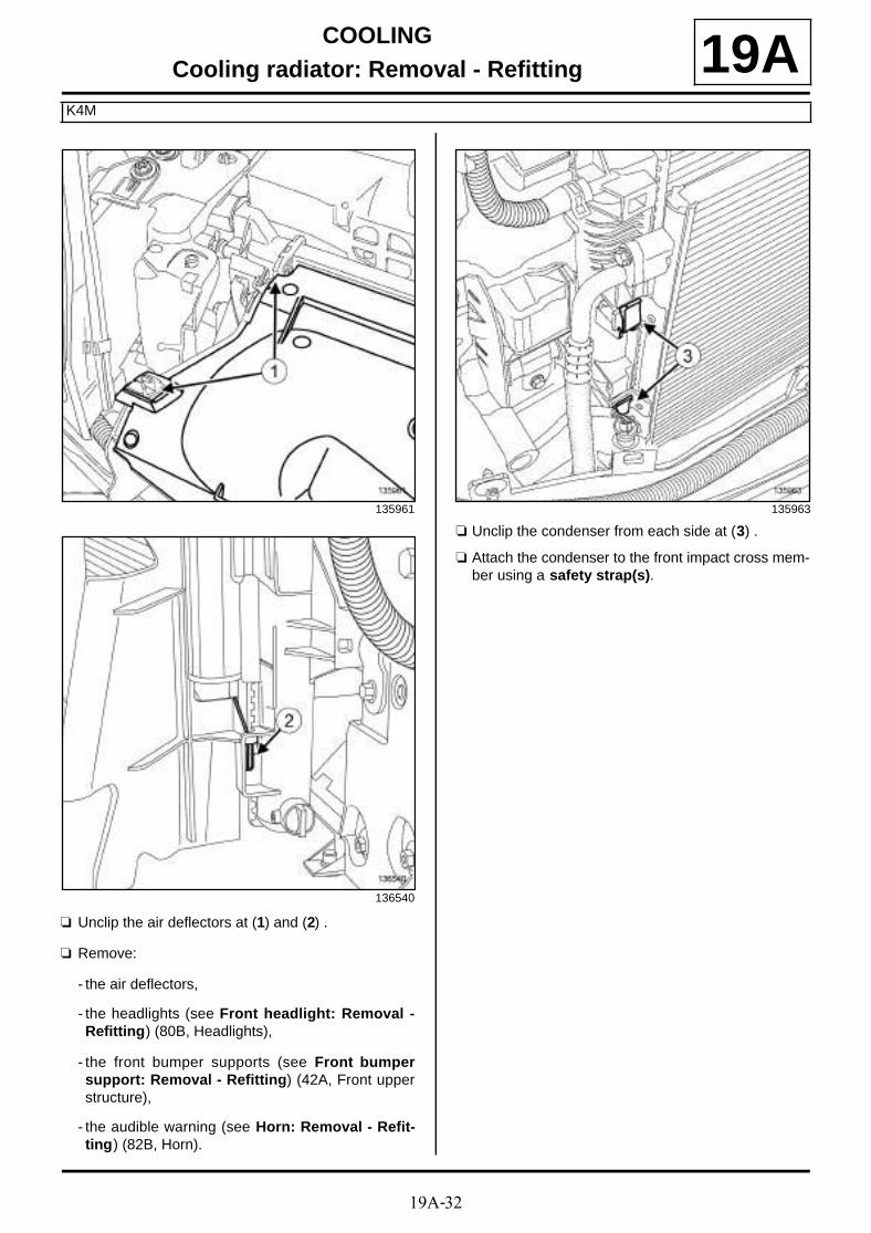
19A-32
COOLINGCooling radiator: Removal - Refitting
K4M
19A
a Unclip the air deflectors at (1) and (2) .
a Remove:
- the air deflectors,
- the headlights (see Front headlight: Removal -Refitting) (80B, Headlights),
- the front bumper supports (see Front bumpersupport: Removal - Refitting) (42A, Front upperstructure),
- the audible warning (see Horn: Removal - Refit-ting) (82B, Horn).
a Unclip the condenser from each side at (3) .
a Attach the condenser to the front impact cross mem-ber using a safety strap(s).
135961
136540
135963
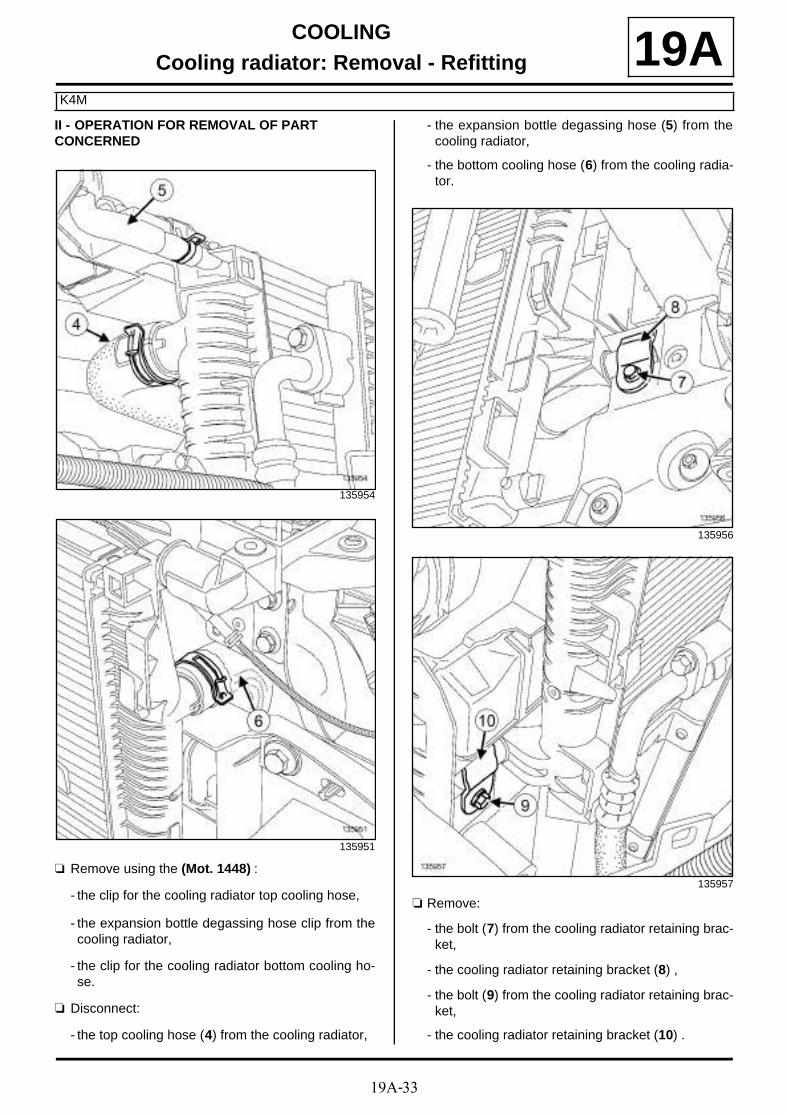
19A-33
COOLINGCooling radiator: Removal - Refitting
K4M
19AII - OPERATION FOR REMOVAL OF PART CONCERNED
a Remove using the (Mot. 1448) :
- the clip for the cooling radiator top cooling hose,
- the expansion bottle degassing hose clip from thecooling radiator,
- the clip for the cooling radiator bottom cooling ho-se.
a Disconnect:
- the top cooling hose (4) from the cooling radiator,
- the expansion bottle degassing hose (5) from thecooling radiator,
- the bottom cooling hose (6) from the cooling radia-tor.
a Remove:
- the bolt (7) from the cooling radiator retaining brac-ket,
- the cooling radiator retaining bracket (8) ,
- the bolt (9) from the cooling radiator retaining brac-ket,
- the cooling radiator retaining bracket (10) .
135954
135951
135956
135957

19A-34
COOLINGCooling radiator: Removal - Refitting
K4M
19Aa Remove the cooling radiator from the front end pa-
nel.
REFITTING
I - REFITTING OPERATION FOR PART CONCERNED
a Refit:
- the cooling radiator to the front end panel,
- the retaining brackets to the cooling radiator,
- the retaining bracket bolts to the cooling radiator.
a Connect:
- the bottom cooling hose to the cooling radiator,
- the expansion bottle degassing hose to the coolingradiator,
- the top cooling hose to the cooling radiator.
a Using the (Mot. 1448), fit:
- the bottom cooling hose clip on the cooling radia-tor,
- the expansion bottle degassing hose clip on thecooling radiator,
- the top cooling hose clip on the cooling radiator.
II - FINAL OPERATION
a Clip the condenser onto the cooling radiator.
a Refit:
- the audible warning (see Horn: Removal - Refit-ting) (82B, Horn),
- the front bumper supports (see Front bumpersupport: Removal - Refitting) (42A, Front upperstructure),
- the headlights (see Front headlight: Removal -Refitting) (80B, Headlights),
- the air deflectors,
- the front bumper (see Front bumper: Removal -Refitting) (55A, Exterior protection),
- the front section of the front wheel arch liners (seeFront wheel arch liner: Removal - Refitting)(55A, Exterior protection),
- the front wheels (see Wheel: Removal - Refitting)(35A, Wheels and tyres),
- the engine cover.
a Connect the battery (see Battery: Removal - Refit-ting) (80A, Battery).
a Fill and bleed the cooling system (see 19A, Coo-ling, Cooling circuit: Draining - Refilling, page19A-17) .
a Refit the engine undertray.

19A-35
COOLINGCooling radiator: Removal - Refitting
K9K
19A
REMOVAL
I - REMOVAL PREPARATION OPERATION
a Position the vehicle on a two-post lift (see Vehicle:Towing and lifting) (02A, Lifting equipment).
a Remove:
- the engine cover,
- the front wheels (see Wheel: Removal - Refitting)(35A, Wheels and tyres),
- the engine undertray bolts,
- the engine undertray,
- the front section of the front wheel arch liners (seeFront wheel arch liner: Removal - Refitting)(55A, Exterior protection),
- the front bumper (see Front bumper: Removal -Refitting) (55A, Exterior protection).
a Drain the cooling system (see 19A, Cooling, Coo-ling circuit: Draining - Refilling, page 19A-17) .
a Remove:
- the cooling radiator top air deflector,
- the side air deflectors of the cooling radiator,
- the headlights (see Front headlight: Removal -Refitting) (80B, Headlights),
- the front bumper supports (see Front bumpersupport: Removal - Refitting) (42A, Front upperstructure),
- the turbocharger air outlet pipe (see 12B, Turbo-charging, Intercooler air inlet pipe: Removal -Refitting, page 12B-41) ,
- the intercooler air inlet pipe (see 12B, Turbochar-ging, Intercooler air inlet pipe: Removal - Refit-ting, page 12B-41) ,
- the intercooler air outlet pipe (see 12B, Turbo-charging, Intercooler air outlet pipe: Removal -Refitting, page 12B-56) ,
- the intercooler (see 12B, Turbocharging, Inter-cooler: Removal - Refitting, page 12B-37) ,
- the audible warning (see Horn: Removal - Refit-ting) (82B, Horn).
a Unclip the air conditioning condenser (1) from thecooling radiator by pulling upwards.
a Slightly separate the air conditioning condenser.
Essential special tooling
Mot. 1448 Long nose pliers for hoseclips.
Mot. 1202-02 Pliers for small hose clips.
Essential equipment
safety strap(s)
IMPORTANT
When working in the engine compartment, takecare as the radiator fan(s) may start up unexpecte-dly (risk of being cut).
To avoid any risk of serious burns when the engine is hot:
- do not open the expansion bottle cap,
- do not drain the cooling system,
- do not open the bleed screw(s).
WARNING
Prepare for the flow of fluid, and protect the sur-rounding components.
135832

19A-36
COOLINGCooling radiator: Removal - Refitting
K9K
19A
a Using a safety strap(s) (2) , attach the air conditio-ning condenser to the front impact cross member.
II - OPERATION FOR REMOVAL OF PART CONCERNED
a Use the tool (Mot. 1448) to separate the cooling ra-diator bottom cooling hose clip (3) from the coolingradiator.
a Disconnect the cooling radiator bottom cooling hosefrom the cooling radiator.
a Use the tool (Mot. 1202-02) to separate the expan-sion bottle top cooling hose clip (4) from the coolingradiator.
a Disconnect the expansion bottle top cooling hosefrom the cooling radiator.
a Use the tool (Mot. 1448) to separate the cooling ra-diator top cooling hose clip (5) from the cooling ra-diator.
a Disconnect the cooling radiator top cooling hosefrom the cooling radiator.
135835
135836
135837
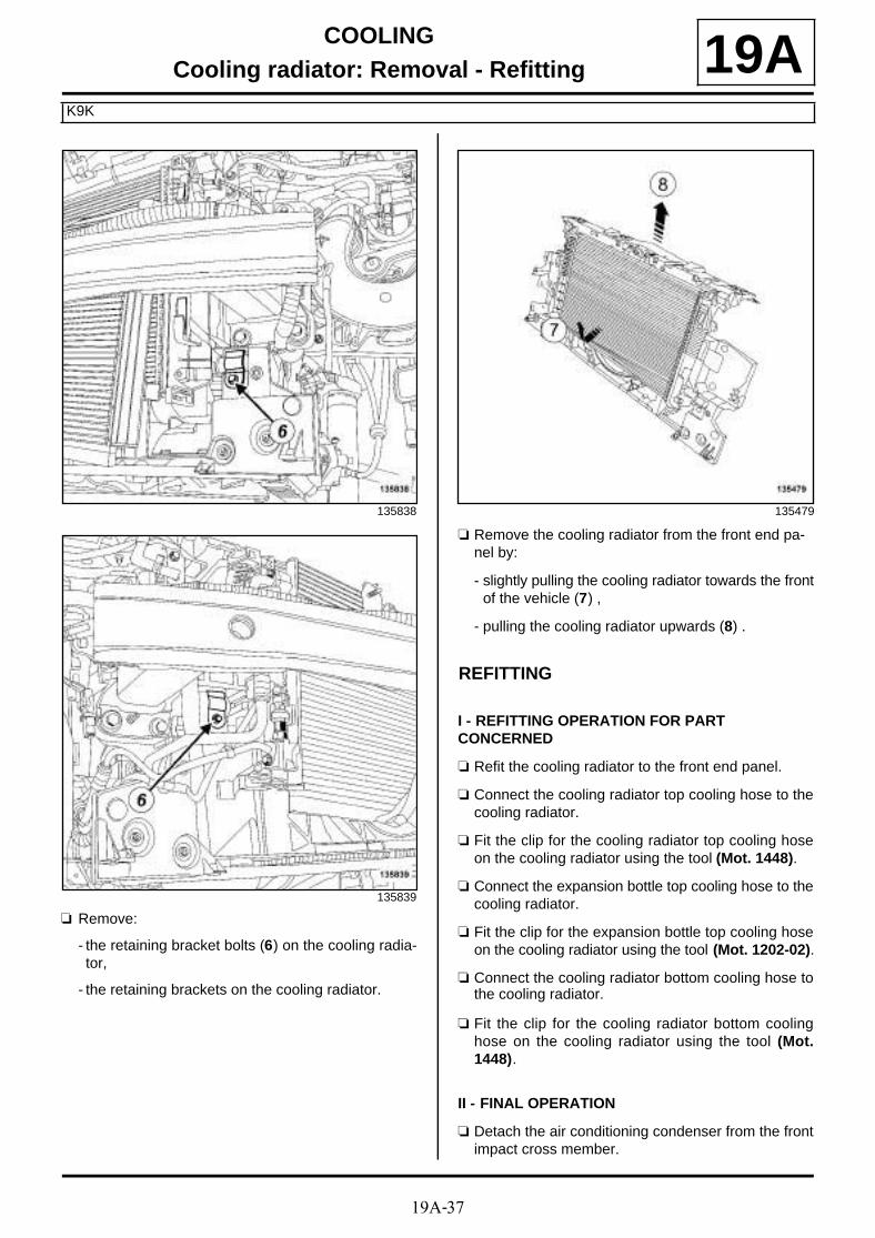
19A-37
COOLINGCooling radiator: Removal - Refitting
K9K
19A
a Remove:
- the retaining bracket bolts (6) on the cooling radia-tor,
- the retaining brackets on the cooling radiator.
a Remove the cooling radiator from the front end pa-nel by:
- slightly pulling the cooling radiator towards the frontof the vehicle (7) ,
- pulling the cooling radiator upwards (8) .
REFITTING
I - REFITTING OPERATION FOR PART CONCERNED
a Refit the cooling radiator to the front end panel.
a Connect the cooling radiator top cooling hose to thecooling radiator.
a Fit the clip for the cooling radiator top cooling hoseon the cooling radiator using the tool (Mot. 1448).
a Connect the expansion bottle top cooling hose to thecooling radiator.
a Fit the clip for the expansion bottle top cooling hoseon the cooling radiator using the tool (Mot. 1202-02).
a Connect the cooling radiator bottom cooling hose tothe cooling radiator.
a Fit the clip for the cooling radiator bottom coolinghose on the cooling radiator using the tool (Mot.1448).
II - FINAL OPERATION
a Detach the air conditioning condenser from the frontimpact cross member.
135838
135839
135479

19A-38
COOLINGCooling radiator: Removal - Refitting
K9K
19Aa Fit the air conditioning condenser.
a Clip the air conditioning condenser onto the coolingradiator.
a Refit:
- the audible warning (see Horn: Removal - Refit-ting) (82B, Horn),
- the intercooler (see 12B, Turbocharging, Inter-cooler: Removal - Refitting, page 12B-37) ,
- the intercooler air outlet pipe (see 12B, Turbo-charging, Intercooler air outlet pipe: Removal -Refitting, page 12B-56) ,
- the intercooler air inlet pipe (see 12B, Turbochar-ging, Intercooler air inlet pipe: Removal - Refit-ting, page 12B-41) ,
- the turbocharger air outlet pipe (see 12B, Turbo-charging, Intercooler air inlet pipe: Removal -Refitting, page 12B-41) ,
- the front bumper supports (see Front bumpersupport: Removal - Refitting) (42A, Front upperstructure),
- the headlights (see Front headlight: Removal -Refitting) (80B, Headlights),
- the side air deflectors of the cooling radiator,
- the cooling radiator top air deflector,
- the front bumper (see Front bumper: Removal -Refitting) (55A, Exterior protection),
- the front section of the front wheel arch liners (seeFront wheel arch liner: Removal - Refitting)(55A, Exterior protection),
- the engine undertray,
- the front wheels (see Wheel: Removal - Refitting)(35A, Wheels and tyres),
- the engine cover.
a Fill and bleed the cooling system (see 19A, Coo-ling, Cooling circuit: Draining - Refilling, page19A-17) .

19A-39
COOLINGCooling radiator: Removal - Refitting
F9Q
19A
REMOVAL
I - REMOVAL PREPARATION OPERATION
a Position the vehicle on a two-post lift (see Vehicle:Towing and lifting) (02A, Lifting equipment).
a Disconnect the battery (see Battery: Removal - Re-fitting) (80A, Battery).
a Remove:
- the engine cover,
- the engine undertray bolts,
- the engine undertray,
- the front wheels (see Wheel: Removal - Refitting)(35A, Wheels and tyres),
- the front section of the front wheel arch liners (seeFront wheel arch liner: Removal - Refitting)(55A, Exterior protection),
- the front bumper (see Front bumper: Removal -Refitting) (55A, Exterior protection).
a Drain the cooling system (see 19A, Cooling, Coo-ling circuit: Draining - Refilling, page 19A-17) .
a Remove:
- the cooling radiator air deflectors,
- the headlights (see Front headlight: Removal -Refitting) (80B, Headlights),
- the front bumper supports (see Front bumpersupport: Removal - Refitting) (42A, Front upperstructure),
- the audible warning (see Horn: Removal - Refit-ting) (82B, Horn),
- the intercooler (see 12B, Turbocharging, Inter-cooler: Removal - Refitting, page 12B-37) .
a Unclip the condenser (1) from the cooling radiator.
Essential special tooling
Mot. 1448 Long nose pliers for hoseclips.
Essential equipment
safety strap(s)
WARNING
Before the operation, protect the electrical accesso-ries to prevent any risk of shor t circuiting and pro-tect the belts to avoid damaging them.
IMPORTANT
When working in the engine compartment, takecare as the radiator fan(s) may start up unexpecte-dly (risk of being cut).
To avoid any risk of serious burns when the engine is hot:
- do not open the expansion bottle cap,
- do not drain the cooling system,
- do not open the bleed screw(s).
WARNING
When carrying out a repair that requires a completechange, it is essential to flush the circuit with cleanwater, blast compressed air through the circuit todrive out the water, fill and bleed the circuit andthen measure the effective protection.
The criteria to be met are:
- protection down to -25˚C ±±±± 2 for cold and tempe-rate countries,
- protection down to -40˚C ±±±± 2 for "extreme cold"countries.
135995

19A-40
COOLINGCooling radiator: Removal - Refitting
F9Q
19A
a Attach the condenser to the front impact cross mem-ber using a safety strap(s).
II - OPERATION FOR REMOVAL OF PART CONCERNED
a Remove the clips (2) from the cooling radiator hosesusing the tool (Mot. 1448).
a Disconnect the cooling radiator hoses.
135996
135997
135998

19A-41
COOLINGCooling radiator: Removal - Refitting
F9Q
19A
a Remove:
- the retaining bracket bolts (3) on the cooling radia-tor,
- the retaining brackets on the cooling radiator,
- the cooling radiator.
REFITTING
I - REFITTING OPERATION FOR PART CONCERNED
a Refit the cooling radiator.
a Connect the cooling radiator hoses.
a Fit the cooling radiator hose clips using the tool(Mot. 1448).
II - FINAL OPERATION
a Detach the condenser from the front impact crossmember.
a Clip the condenser onto the cooling radiator.
a Refit:
- the intercooler (see 12B, Turbocharging, Inter-cooler: Removal - Refitting, page 12B-37) ,
- the audible warning (see Horn: Removal - Refit-ting) (82B, Horn),
- the front bumper supports (see Front bumpersupport: Removal - Refitting) (42A, Front upperstructure),
- the headlights (see Front headlight: Removal -Refitting) (80B, Headlights),
- the cooling radiator side air deflectors,
- the cooling radiator top air deflector.
- the front bumper (see Front bumper: Removal -Refitting) (55A, Exterior protection),
- the front section of the front wheel arch liners (seeFront wheel arch liner: Removal - Refitting)(55A, Exterior protection),
- the front wheels (see Wheel: Removal - Refitting)(35A, Wheels and tyres),
- the engine undertray,
- the engine cover.
a Fill and bleed the cooling system (see 19A, Coo-ling, Cooling circuit: Draining - Refilling, page19A-17) .
135999
136000
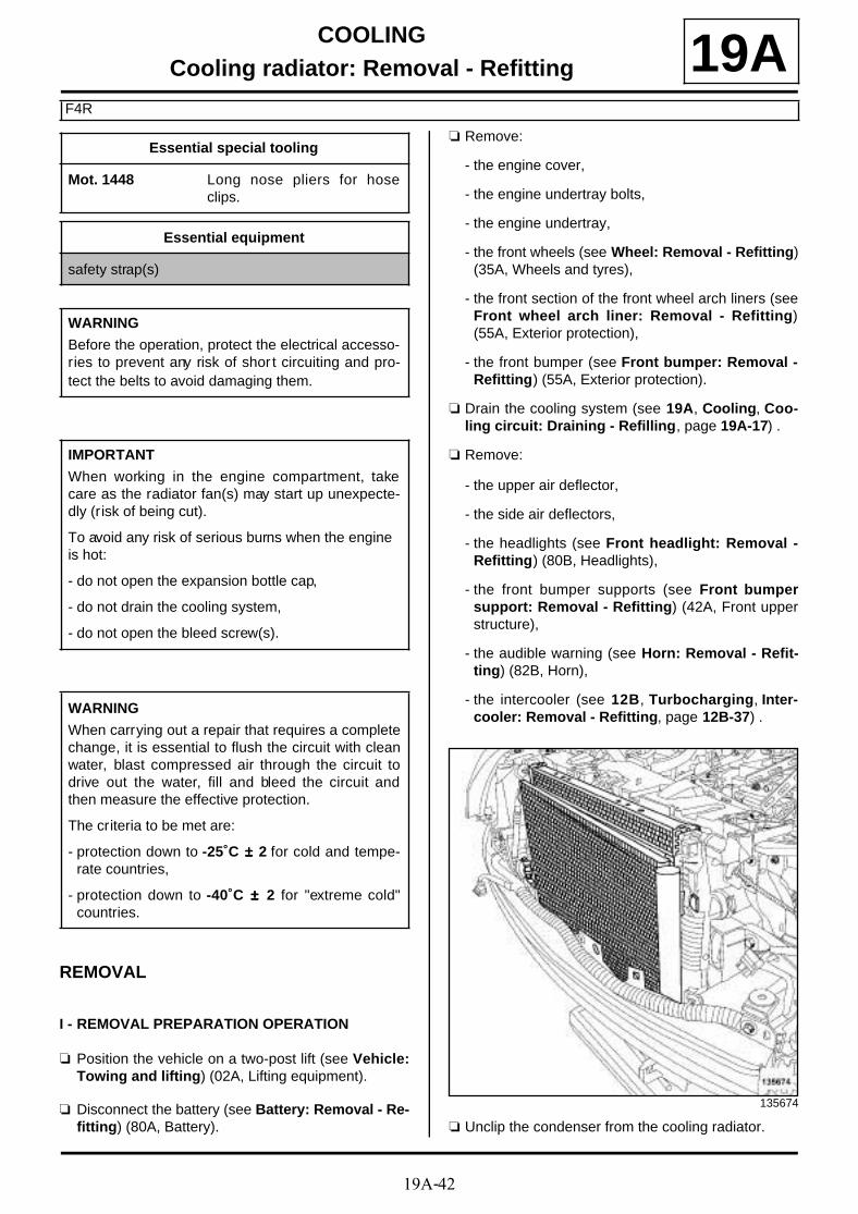
19A-42
COOLINGCooling radiator: Removal - Refitting
F4R
19A
REMOVAL
I - REMOVAL PREPARATION OPERATION
a Position the vehicle on a two-post lift (see Vehicle:Towing and lifting) (02A, Lifting equipment).
a Disconnect the battery (see Battery: Removal - Re-fitting) (80A, Battery).
a Remove:
- the engine cover,
- the engine undertray bolts,
- the engine undertray,
- the front wheels (see Wheel: Removal - Refitting)(35A, Wheels and tyres),
- the front section of the front wheel arch liners (seeFront wheel arch liner: Removal - Refitting)(55A, Exterior protection),
- the front bumper (see Front bumper: Removal -Refitting) (55A, Exterior protection).
a Drain the cooling system (see 19A, Cooling, Coo-ling circuit: Draining - Refilling, page 19A-17) .
a Remove:
- the upper air deflector,
- the side air deflectors,
- the headlights (see Front headlight: Removal -Refitting) (80B, Headlights),
- the front bumper supports (see Front bumpersupport: Removal - Refitting) (42A, Front upperstructure),
- the audible warning (see Horn: Removal - Refit-ting) (82B, Horn),
- the intercooler (see 12B, Turbocharging, Inter-cooler: Removal - Refitting, page 12B-37) .
a Unclip the condenser from the cooling radiator.
Essential special tooling
Mot. 1448 Long nose pliers for hoseclips.
Essential equipment
safety strap(s)
WARNING
Before the operation, protect the electrical accesso-ries to prevent any risk of shor t circuiting and pro-tect the belts to avoid damaging them.
IMPORTANT
When working in the engine compartment, takecare as the radiator fan(s) may start up unexpecte-dly (risk of being cut).
To avoid any risk of serious burns when the engine is hot:
- do not open the expansion bottle cap,
- do not drain the cooling system,
- do not open the bleed screw(s).
WARNING
When carrying out a repair that requires a completechange, it is essential to flush the circuit with cleanwater, blast compressed air through the circuit todrive out the water, fill and bleed the circuit andthen measure the effective protection.
The criteria to be met are:
- protection down to -25˚C ±±±± 2 for cold and tempe-rate countries,
- protection down to -40˚C ±±±± 2 for "extreme cold"countries.
135674
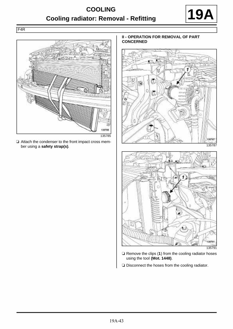
19A-43
COOLINGCooling radiator: Removal - Refitting
F4R
19A
a Attach the condenser to the front impact cross mem-ber using a safety strap(s).
II - OPERATION FOR REMOVAL OF PART CONCERNED
a Remove the clips (1) from the cooling radiator hosesusing the tool (Mot. 1448).
a Disconnect the hoses from the cooling radiator.
135785
135787
135791

19A-44
COOLINGCooling radiator: Removal - Refitting
F4R
19A
a Remove:
- the retaining bracket bolts (2) on the cooling radia-tor,
- the retaining brackets on the cooling radiator,
- the cooling radiator.
REFITTING
I - REFITTING OPERATION FOR PART CONCERNED
a Refit:
- the cooling radiator,
- the retaining brackets on the cooling radiator.
a Connect the cooling radiator hoses.
a Fit the cooling radiator hose clips using the tool(Mot. 1448).
II - FINAL OPERATION
a Detach the condenser from the front impact crossmember.
a Clip on the cooling radiator condenser.
a Refit:
- the intercooler (see 12B, Turbocharging, Inter-cooler: Removal - Refitting, page 12B-37) ,
- the audible warning (see Horn: Removal - Refit-ting) (82B, Horn),
- the front bumper supports (see Front bumpersupport: Removal - Refitting) (42A, Front upperstructure),
- the headlights (see Front headlight: Removal -Refitting) (80B, Headlights),
- the side air deflectors,
- the upper air deflector,
- the front bumper (see Front bumper: Removal -Refitting) (55A, Exterior protection),
- the front section of the front wheel arch liners (seeFront wheel arch liner: Removal - Refitting)(55A, Exterior protection),
- the front wheels (see Wheel: Removal - Refitting)(35A, Wheels and tyres),
- the engine undertray,
- the engine cover.
a Connect the battery (see Battery: Removal - Refit-ting) (80A, Battery).
a Fill and bleed the cooling system (see 19A, Coo-ling, Cooling circuit: Draining - Refilling, page19A-17) .
135788
135790

19A-45
COOLINGWater pump: Removal - Refitting
F4R
19A
REMOVAL
I - REMOVAL PREPARATION OPERATION
a Position the vehicle on a two-post lift (see Vehicle:Towing and lifting) (02A, Lifting equipment).
a Remove:
- the engine cover,
- the battery (see Battery: Removal - Refitting)(80A, Battery),
- the battery tray (see Battery tray: Removal - Re-fitting) (80A, Battery),
- the engine undertray bolts,
- the engine undertray,
- the front wheels (see Wheel: Removal - Refitting)(35A, Wheels and tyres),
- the front section of the front wheel arch liners (seeFront wheel arch liner: Removal - Refitting)(55A, Exterior protection),
- the front bumper (see Front bumper: Removal -Refitting) (55A, Exterior protection),
- the radiator mounting cross member (see Radiatorsupport cross member: Removal - Refitting)(31A, Front axle components),
- the accessories belt (see 11A, Top and front ofengine, Accessories belt: Removal - Refitting,page 11A-7) ,
- the crankshaft accessories pulley (see 11A, Topand front of engine, Crankshaft accessoriespulley: Removal - Refitting, page 11A-15) ,
- the lower engine tie-bar (see 19D, Engine moun-ting, Lower engine tie-bar: Removal - Refitting,page 19D-33) ,
- the windscreen wiper arms (see Windscreen wi-per arm: Removal - Refitting) (85A, Wiping -Washing),
- the scuttle panel grille (see Scuttle panel grille:Removal - Refitting) (56A, Exterior equipment),
- the scoop under the scuttle panel grille (see Scoopunder scuttle panel grille: Removal - Refitting)(56A, Exterior equipment),
- the right-hand suspended engine mounting (see19D, Engine mounting, Right-hand suspendedengine mounting: Removal - Refitting, page19D-18) ,
- the timing belt (see 11A, Top and front of engine,Timing belt: Removal - Refitting, page 11A-29) .
a Drain the cooling system (see 19A, Cooling, Coo-ling circuit: Draining - Refilling, page 19A-17) .
Tightening torquesm
coolant pump bolts 12 N.m
IMPORTANT
When working in the engine compartment, takecare as the radiator fan(s) may start up unexpecte-dly (risk of being cut).
To avoid any risk of serious burns when the engine is hot:
- do not open the expansion bottle cap,
- do not drain the cooling system,
- do not open the bleed screw(s).
WARNING
Prepare for the flow of fluid, and protect the sur-rounding components.
WARNING
When carrying out a repair that requires a completechange, it is essential to flush the circuit with cleanwater, blast compressed air through the circuit todrive out the water, fill and bleed the circuit andthen measure the effective protection.
The criteria to be met are:
- protection down to -25˚C ±±±± 2 for cold and tempe-rate countries,
- protection down to -40˚C ±±±± 2 for "extreme cold"countries.

19A-46
COOLINGWater pump: Removal - Refitting
F4R
19AII - OPERATION FOR REMOVAL OF PART CONCERNED
a
a Remove:
- the coolant pump bolts (1) ,
- the coolant pump,
- the coolant pump seal.
REFITTING
I - REFITTING PREPARATION OPERATION
a parts always to be replaced: Coolant pump seal(10,06,01,21).
a Clean the joint faces with SUPER CLEANINGAGENT FOR JOINT FACES (see Vehicle: Partsand ingredients for the repairwork) (04B, Consu-mables - Products).
II - REFITTING OPERATION FOR PARTS CONCERNED
a Refit a new gasket to the coolant pump.
a Coat the coolant pump bolts with FRENETANCHE(see Vehicle: Parts and ingredients for the repai-rwork) (04B, Consumables - Products).
a Refit:
- the coolant pump,
- the coolant pump bolts.
136494
Note:
The coolant pump bolts are not the same length,mark their position.
IMPORTANT
Wear goggles with side protectors for this opera-tion.
WARNING
Do not scrape the joint faces of the aluminium,any damage caused to the joint face will result ina risk of leaks.
WARNING
To ensure proper sealing, the gasket surfacesmust be clean, dry and not greasy (avoid any fin-ger marks).

19A-47
COOLINGWater pump: Removal - Refitting
F4R
19A
a Tighten to torque and in order the coolant pumpbolts (12 N.m).
III - FINAL OPERATION
a Refit:
- the timing belt (see 11A, Top and front of engine,Timing belt: Removal - Refitting, page 11A-29) ,
- the right-hand suspended engine mounting (see19D, Engine mounting, Right-hand suspendedengine mounting: Removal - Refitting, page19D-18) ,
- the scoop under the scuttle panel grille (see Scoopunder scuttle panel grille: Removal - Refitting)(56A, Exterior equipment),
- the scuttle panel grille (see Scuttle panel grille:Removal - Refitting) (56A, Exterior equipment),
- the windscreen wiper arms (see Windscreen wi-per arm: Removal - Refitting) (85A, Wiping -Washing),
- the lower engine tie-bar (see 19D, Engine moun-ting, Lower engine tie-bar: Removal - Refitting,page 19D-33) ,
- the crankshaft accessories pulley (see 11A, Topand front of engine, Crankshaft accessoriespulley: Removal - Refitting, page 11A-15) ,
- the accessories belt (see 11A, Top and front ofengine, Accessories belt: Removal - Refitting,page 11A-7) ,
- the radiator mounting cross member (see Radiatorsupport cross member: Removal - Refitting)(31A, Front axle components),
- the front bumper (see Front bumper: Removal -Refitting) (55A, Exterior protection),
- the front section of the front wheel arch liners (seeFront wheel arch liner: Removal - Refitting)(55A, Exterior protection),
- the front wheels (see Wheel: Removal - Refitting)(35A, Wheels and tyres),
- the engine undertray,
- the battery tray (see Battery tray: Removal - Re-fitting) (80A, Battery),
- the battery (see Battery: Removal - Refitting)(80A, Battery),
- the engine cover.
a Fill and bleed the cooling system (see 19A, Coo-ling, Cooling circuit: Draining - Refilling, page19A-17) .
136494

19A-48
COOLINGWater pump: Removal - Refitting
K4M
19A
REMOVAL
I - REMOVAL PREPARATION OPERATION
a Position the vehicle on a two-post lift (see Vehicle:Towing and lifting) (02A, Lifting equipment).
a Disconnect the battery (see Battery: Removal - Re-fitting) (80A, Battery).
a Remove:
- the engine cover,
- the throttle valve (see 12A, Fuel mixture, Throttlevalve: Removal - Refitting, page 12A-17) ,
- the front wheels (see Wheel: Removal - Refitting)(35A, Wheels and tyres),
- the front section of the front wheel arch liners (seeFront wheel arch liner: Removal - Refitting)(55A, Exterior protection),
- the engine undertray bolts,
- the engine undertray,
- the front bumper (see Front bumper: Removal -Refitting) (55A, Exterior protection).
a Drain the cooling system (see 19A, Cooling, Coo-ling circuit: Draining - Refilling, page 19A-17) .
a Remove:
- the windscreen wiper arms (see Windscreen wi-per arm: Removal - Refitting) (85A, Wiping -Washing),
- the scuttle panel grille (see Scuttle panel grille:Removal - Refitting) (56A, Exterior equipment),
- the scoop under the scuttle panel grille (see Scoopunder scuttle panel grille: Removal - Refitting)(56A, Exterior equipment),
- the lower engine tie-bar (see 19D, Engine moun-ting, Lower engine tie-bar: Removal - Refitting,page 19D-33) ,
- the accessories belt (see 11A, Top and front ofengine, Accessories belt: Removal - Refitting,page 11A-7) ,
- the crankshaft accessories pulley (see 11A, Topand front of engine, Crankshaft accessoriespulley: Removal - Refitting, page 11A-15) ,
- the right-hand suspended engine mounting (see19D, Engine mounting, Right-hand suspendedengine mounting: Removal - Refitting, page19D-18) ,
- the timing belt (see 11A, Top and front of engine,Timing belt: Removal - Refitting, page 11A-29) .
Tightening torquesm
bolts 2 to 8 of the coo-lant pump
10 N.m
bolt 1 of the coolantpump
27 N.m
IMPORTANT
When working in the engine compartment, takecare as the radiator fan(s) may start up unexpecte-dly (risk of being cut).
To avoid any risk of serious burns when the engine is hot:
- do not open the expansion bottle cap,
- do not drain the cooling system,
- do not open the bleed screw(s).
WARNING
Prepare for the flow of fluid, and protect the sur-rounding components.
WARNING
When carrying out a repair that requires a completechange, it is essential to flush the circuit with cleanwater, blast compressed air through the circuit todrive out the water, fill and bleed the circuit andthen measure the effective protection.
The criteria to be met are:
- protection down to -25˚C ±±±± 2 for cold and tempe-rate countries,
- protection down to -40˚C ±±±± 2 for "extreme cold"countries.

19A-49
COOLINGWater pump: Removal - Refitting
K4M
19AII - OPERATION FOR REMOVAL OF PART CONCERNED
a Remove:
- the coolant pump bolts (1) ,
- the coolant pump.
REFITTING
I - REFITTING PREPARATION OPERATION
a
a Use SUPER CLEANING AGENT FOR JOINT FA-CES (see Vehicle: Parts and ingredients for the repairwork) (04B, Consumables - Products) to clean:
- the coolant pump sealing face if it is to be reused,
- the cylinder block gasket face.
a Use SURFACE CLEANER (see Vehicle: Parts and ingredients for the repairwork) (04B, Consu-mables - Products) to degrease:
- the coolant pump sealing face if it is to be reused,
- the cylinder block gasket face.
a
a Apply a bead (2) of RESIN ADHESIVE (see Vehi-cle: Parts and ingredients for the repairwork)(04B, Consumables - Products) with a width of 0,6 à1 mm .
14505
WARNING
Do not scrape the joint faces of the aluminium,any damage caused to the joint face will result ina risk of leaks.
WARNING
To ensure proper sealing, the gasket surfacesmust be clean, dry and not greasy (avoid any fin-ger marks).
IMPORTANT
Wear goggles with side protectors for this opera-tion.
IMPORTANT
Wear leaktight gloves (Nitrile type) for this opera-tion.
10063
WARNING
Applying excess sealant could cause it to besqueezed out when parts are tightened. A mix-ture of sealant and fluid could damage certaincomponents (engine, radiator, etc.).

19A-50
COOLINGWater pump: Removal - Refitting
K4M
19AII - REFITTING OPERATION FOR PART CONCERNED
a
a Refit the coolant pump.
a Fit the coolant pump bolts without tightening them.
a Tighten to torque and in order:
- the bolts 2 to 8 of the coolant pump (10 N.m),
- the bolt 1 of the coolant pump (27 N.m).
III - FINAL OPERATION
a Refit:
- the timing belt (see 11A, Top and front of engine,Timing belt: Removal - Refitting, page 11A-29) ,
- the right-hand suspended engine mounting (see19D, Engine mounting, Right-hand suspendedengine mounting: Removal - Refitting, page19D-18) ,
- the crankshaft accessories pulley (see 11A, Topand front of engine, Crankshaft accessoriespulley: Removal - Refitting, page 11A-15) ,
- the accessories belt (see 11A, Top and front ofengine, Accessories belt: Removal - Refitting,page 11A-7) ,
- the lower engine tie-bar (see 19D, Engine moun-ting, Lower engine tie-bar: Removal - Refitting,page 19D-33) ,
- the scoop under the scuttle panel grille (see Scoopunder scuttle panel grille: Removal - Refitting)(56A, Exterior equipment),
- the scuttle panel grille (see Scuttle panel grille:Removal - Refitting) (56A, Exterior equipment),
- the windscreen wiper arms (see Windscreen wi-per arm: Removal - Refitting) (85A, Wiping -Washing),
- the front bumper (see Front bumper: Removal -Refitting) (55A, Exterior protection),
- the front section of the front wheel arch liners (seeFront wheel arch liner: Removal - Refitting)(55A, Exterior protection),
- the front wheels (see Wheel: Removal - Refitting)(35A, Wheels and tyres),
- the throttle valve (see 12A, Fuel mixture, Throttlevalve: Removal - Refitting, page 12A-17) ,
- the engine cover.
a Connect the battery (see Battery: Removal - Refit-ting) (80A, Battery).
a Fill and bleed the cooling system (see 19A, Coo-ling, Cooling circuit: Draining - Refilling, page19A-17) .
a Refit the engine undertray.
14505
Note:
Apply one to two drops of FRENETANCHE (seeVehicle: Parts and ingredients for the repai-rwork) (04B, Consumables - Products) to thecoolant pump bolts (1) and (5) .

19A-51
COOLINGWater pump: Removal - Refitting
K9K
19A
REMOVAL
I - REMOVAL PREPARATION OPERATION
a Position the vehicle on a two-post lift (see Vehicle:Towing and lifting) (02A, Lifting equipment).
a Disconnect the battery (see Battery : Removal -Refitting) (80A, Battery).
a Remove:
- the engine cover,
- the front wheels (see Wheel: Removal - Refitting)(35A, Wheels and tyres),
- the front section of the front wheel arch liners (seeFront wheel arch liner: Removal - Refitting)(55A, Exterior protection),
- the engine undertray bolts,
- the engine undertray,
- the front bumper (see Front bumper: Removal -Refitting) (55A, Exterior protection),
- the accessories belt (see 11A, Top and front ofengine, Accessories belt: Removal - Refitting,page 11A-7) .
a Drain the cooling system (see 19A, Cooling, Coo-ling circuit: Draining - Refilling, page 19A-17) .
a Remove:
- the windscreen wiper arms (see Windscreen wi-per arm: Removal - Refitting) (85A, Wiping -Washing),
- the scuttle panel grille (see Scuttle panel grille:Removal - Refitting) (56A, Exterior equipment),
- the scoop under the scuttle panel grille (see Scoopunder scuttle panel grille: Removal - Refitting)(56A, Exterior equipment),
- the right-hand suspended engine mounting (see19D, Engine mounting, Right-hand suspendedengine mounting: Removal - Refitting, page19D-18) ,
- the timing belt (see 11A, Top and front of engine,Timing belt: Removal - Refitting, page 11A-29) .
a Remove the alternator upper bolt (1) .
a Loosen the alternator lower bolt (2) .
a Tilt the alternator slightly towards the front of the ve-hicle.
a Remove:
- the bolts (3) from the inner cover,
- the inner cover.
Tightening torquesm
coolant pump bolts 10 N.m
alternator lower bolt 25 N.m
alternator upper bolt 25 N.m
IMPORTANT
Wear leaktight gloves (Nitrile type) for this opera-tion.
123969
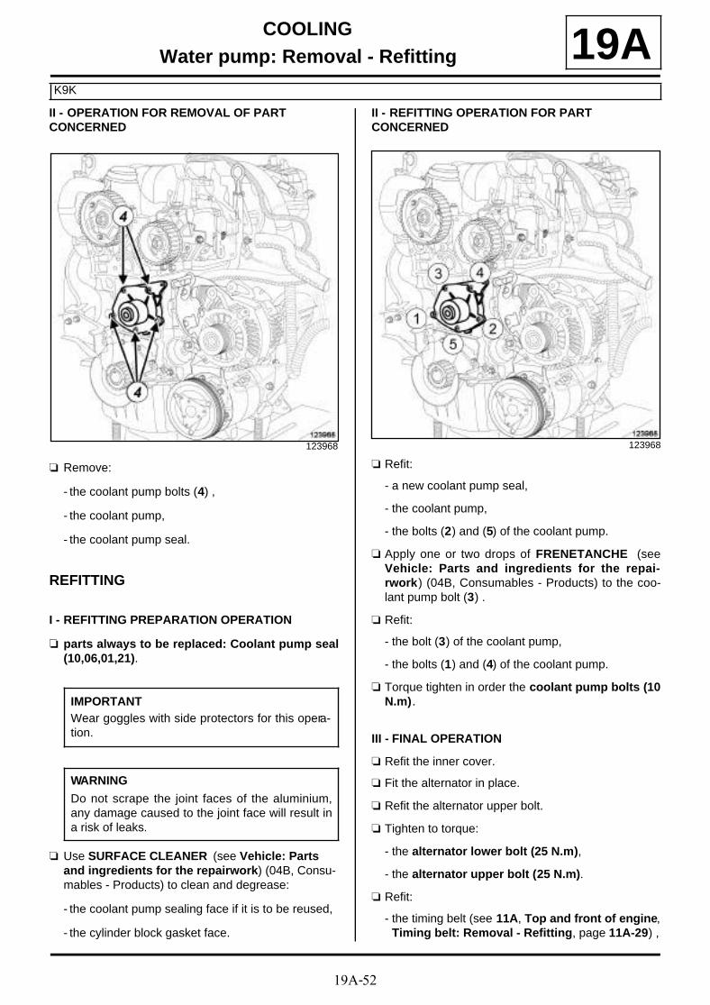
19A-52
COOLINGWater pump: Removal - Refitting
K9K
19AII - OPERATION FOR REMOVAL OF PART CONCERNED
a Remove:
- the coolant pump bolts (4) ,
- the coolant pump,
- the coolant pump seal.
REFITTING
I - REFITTING PREPARATION OPERATION
a parts always to be replaced: Coolant pump seal(10,06,01,21).
a Use SURFACE CLEANER (see Vehicle: Parts and ingredients for the repairwork) (04B, Consu-mables - Products) to clean and degrease:
- the coolant pump sealing face if it is to be reused,
- the cylinder block gasket face.
II - REFITTING OPERATION FOR PART CONCERNED
a Refit:
- a new coolant pump seal,
- the coolant pump,
- the bolts (2) and (5) of the coolant pump.
a Apply one or two drops of FRENETANCHE (seeVehicle: Parts and ingredients for the repai-rwork) (04B, Consumables - Products) to the coo-lant pump bolt (3) .
a Refit:
- the bolt (3) of the coolant pump,
- the bolts (1) and (4) of the coolant pump.
a Torque tighten in order the coolant pump bolts (10N.m).
III - FINAL OPERATION
a Refit the inner cover.
a Fit the alternator in place.
a Refit the alternator upper bolt.
a Tighten to torque:
- the alternator lower bolt (25 N.m),
- the alternator upper bolt (25 N.m).
a Refit:
- the timing belt (see 11A, Top and front of engine,Timing belt: Removal - Refitting, page 11A-29) ,
123968
IMPORTANTWear goggles with side protectors for this opera-tion.
WARNING
Do not scrape the joint faces of the aluminium,any damage caused to the joint face will result ina risk of leaks.
123968
19A-53
COOLINGWater pump: Removal - Refitting
K9K
19A- the right-hand suspended engine mounting (see19D, Engine mounting, Right-hand suspendedengine mounting: Removal - Refitting, page19D-18) ,
- the scoop under the scuttle panel grille (see Scoopunder scuttle panel grille: Removal - Refitting)(56A, Exterior equipment),
- the scuttle panel grille (see Scuttle panel grille:Removal - Refitting) (56A, Exterior equipment),
- the windscreen wiper arms (see Windscreen wi-per arm: Removal - Refitting) (85A, Wiping -Washing),
- the accessories belt (see 11A, Top and front ofengine, Accessories belt: Removal - Refitting,page 11A-7) ,
- the front bumper (see Front bumper: Removal -Refitting) (55A, Exterior protection),
- the engine undertray,
- the front section of the front wheel arch liners (seeFront wheel arch liner: Removal - Refitting)(55A, Exterior protection),
- the front wheels (see Wheel: Removal - Refitting)(35A, Wheels and tyres),
- the engine cover.
a Connect the battery (see Battery : Removal - Refit-ting) (80A, Battery).
a Fill and bleed the cooling system (see 19A, Coo-ling, Cooling circuit: Draining - Refilling, page19A-17) .

19A-54
COOLINGWater pump: Removal - Refitting
F9Q
19A
REMOVAL
I - REMOVAL PREPARATION OPERATION
a Position the vehicle on a two-post lift (see Vehicle:Towing and lifting) (02A, Lifting equipment).
a Disconnect the battery (see Battery : Removal -Refitting) (80A, Battery).
a Remove:
- the engine undertray bolts,
- the engine undertray.
a Drain the cooling system (see 19A, Cooling, Coo-ling circuit: Draining - Refilling, page 19A-17) .
a Remove:
- the engine cover,
- the scuttle panel grille (see Scuttle panel grille:Removal - Refitting) (56A, Exterior equipment),
- the scoop under the scuttle panel grille (see Scoopunder scuttle panel grille: Removal - Refitting)(56A, Exterior equipment),
- the front right-hand wheel (see Wheel: Removal -Refitting) (35A, Wheels and tyres),
- the front right-hand wheel arch liner (see Frontwheel arch liner: Removal - Refitting) (55A, Ex-terior protection),
- the accessories belt (see 11A, Top and front ofengine, Accessories belt: Removal - Refitting,page 11A-7) ,
- the lower engine tie-bar (see 19D, Engine moun-ting, Lower engine tie-bar: Removal - Refitting,page 19D-33) ,
- the crankshaft accessories pulley (see 11A, Topand front of engine, Crankshaft accessoriespulley: Removal - Refitting, page 11A-15) ,
- the right-hand suspended engine mounting (see19D, Engine mounting, Right-hand suspendedengine mounting: Removal - Refitting, page19D-18) ,
- the timing belt (see 11A, Top and front of engine,Timing belt: Removal - Refitting, page 11A-29) .
Tightening torquesm
coolant pump bolts 12 N.m
IMPORTANT
When working in the engine compartment, takecare as the radiator fan(s) may start up unexpecte-dly (risk of being cut).
To avoid any risk of serious burns when the engine is hot:
- do not open the expansion bottle cap,
- do not drain the cooling system,
- do not open the bleed screw(s).
WARNING
Prepare for the flow of fluid, and protect the sur-rounding components.
WARNING
When carrying out a repair that requires a completechange, it is essential to flush the circuit with cleanwater, blast compressed air through the circuit todrive out the water, fill and bleed the circuit andthen measure the effective protection.
The criteria to be met are:
- protection down to -25˚C ±±±± 2 for cold and tempe-rate countries,
- protection down to -40˚C ±±±± 2 for "extreme cold"countries.
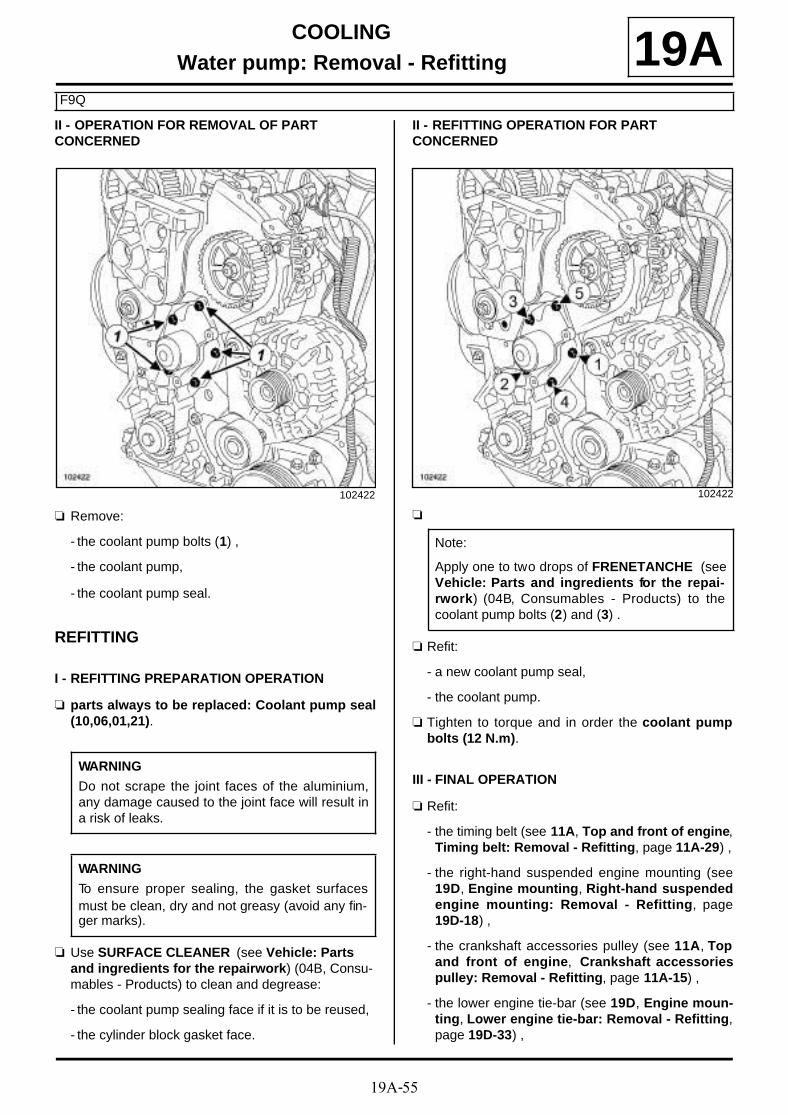
19A-55
COOLINGWater pump: Removal - Refitting
F9Q
19AII - OPERATION FOR REMOVAL OF PART CONCERNED
a Remove:
- the coolant pump bolts (1) ,
- the coolant pump,
- the coolant pump seal.
REFITTING
I - REFITTING PREPARATION OPERATION
a parts always to be replaced: Coolant pump seal(10,06,01,21).
a Use SURFACE CLEANER (see Vehicle: Parts and ingredients for the repairwork) (04B, Consu-mables - Products) to clean and degrease:
- the coolant pump sealing face if it is to be reused,
- the cylinder block gasket face.
II - REFITTING OPERATION FOR PART CONCERNED
a
a Refit:
- a new coolant pump seal,
- the coolant pump.
a Tighten to torque and in order the coolant pumpbolts (12 N.m).
III - FINAL OPERATION
a Refit:
- the timing belt (see 11A, Top and front of engine,Timing belt: Removal - Refitting, page 11A-29) ,
- the right-hand suspended engine mounting (see19D, Engine mounting, Right-hand suspendedengine mounting: Removal - Refitting, page19D-18) ,
- the crankshaft accessories pulley (see 11A, Topand front of engine, Crankshaft accessoriespulley: Removal - Refitting, page 11A-15) ,
- the lower engine tie-bar (see 19D, Engine moun-ting, Lower engine tie-bar: Removal - Refitting,page 19D-33) ,
102422
WARNING
Do not scrape the joint faces of the aluminium,any damage caused to the joint face will result ina risk of leaks.
WARNING
To ensure proper sealing, the gasket surfacesmust be clean, dry and not greasy (avoid any fin-ger marks).
102422
Note:
Apply one to two drops of FRENETANCHE (seeVehicle: Parts and ingredients for the repai-rwork) (04B, Consumables - Products) to thecoolant pump bolts (2) and (3) .

19A-56
COOLINGWater pump: Removal - Refitting
F9Q
19A- the accessories belt (see 11A, Top and front ofengine, Accessories belt: Removal - Refitting,page 11A-7) ,
- the front right-hand wheel arch liner (see Frontwheel arch liner: Removal - Refitting) (55A, Ex-terior protection),
- the front right-hand wheel (see Wheel: Removal -Refitting) (35A, Wheels and tyres),
- the scoop under the scuttle panel grille (see Scoopunder scuttle panel grille: Removal - Refitting)(56A, Exterior equipment),
- the scuttle panel grille (see Scuttle panel grille:Removal - Refitting) (56A, Exterior equipment),
- the engine cover.
a Connect the battery (see Battery : Removal - Refit-ting) (80A, Battery).
a Fill and bleed the cooling system (see 19A, Coo-ling, Cooling circuit: Draining - Refilling, page19A-17) .
a Refit the engine undertray.
19A-57
COOLINGThermostat: Removal - Refitting
F9Q or K4M or K9K
19Aa The thermostat cannot be separated from the water
chamber.
Replace the « water chamber - thermostat » assem-bly if the thermostat is faulty (see 19A, Cooling, Ple-num chamber: Removal - Refitting, page 19A-61).

19A-58
COOLINGThermostat: Removal - Refitting
F4R
19A
REMOVAL
I - REMOVAL PREPARATION OPERATION
a Position the vehicle on a two-post lift (see Vehicle:Towing and lifting) (02A, Lifting equipment).
a Remove:
- the engine cover,
- the front wheels (see Wheel: Removal - Refitting)(35A, Wheels and tyres),
- the front section of the front wheel arch liners (seeFront wheel arch liner: Removal - Refitting)(55A, Exterior protection),
- the engine undertray bolts,
- the engine undertray,
- the front bumper (see Front bumper: Removal -Refitting) (55A, Exterior protection).
a Drain the cooling system (see 19A, Cooling, Coo-ling circuit: Draining - Refilling, page 19A-17) .
a Remove the intercooler air outlet pipe bolts (1) .
a Move the intercooler outlet air pipe to one side.
a Remove the throttle valve (see 12A, Fuel mixture,Throttle valve: Removal - Refitting, page 12A-17).
Essential special tooling
Mot. 1448 Long nose pliers for hoseclips.
IMPORTANT
When working in the engine compartment, takecare as the radiator fan(s) may start up unexpecte-dly (risk of being cut).
To avoid any risk of serious burns when the engine is hot:
- do not open the expansion bottle cap,
- do not drain the cooling system,
- do not open the bleed screw(s).
WARNING
When carrying out a repair that requires a completechange, it is essential to flush the circuit with cleanwater, blast compressed air through the circuit todrive out the water, fill and bleed the circuit andthen measure the effective protection.
The criteria to be met are:
- protection down to -25˚C ±±±± 2 for cold and tempe-rate countries,
- protection down to -40˚C ±±±± 2 for "extreme cold"countries.
WARNING
Before the operation, protect the electrical accesso-ries to prevent any risk of shor t circuiting and pro-tect the belts to avoid damaging them.
135796

19A-59
COOLINGThermostat: Removal - Refitting
F4R
19AII - OPERATION FOR REMOVAL OF PART CONCERNED
a Using the tool (Mot. 1448), separate the top hoseclip (2) on the coolant outlet unit.
a Disconnect the top hose from the coolant outlet unit.
a Remove:
- the thermostat cover bolts (3) ,
- the thermostat cover.
a Remove:
- the thermostat (4) ,
- the thermostat seal.
REFITTING
I - REFITTING PREPARATION OPERATION
a parts always to be replaced: Thermostat seal(10,06,03,03).
a Use SURFACE CLEANER (see Vehicle: Partsand ingredients for the repairwork) (04B, Consu-mables - Products) to clean and degrease the ther-mostat housing.
II - REFITTING OPERATION FOR PART CONCERNED
a Refit:
- a new seal on the thermostat,
- the thermostat,
- the thermostat cover.
a Connect the top hose to the coolant outlet unit.
135697
136520
123733
WARNING
To ensure proper sealing, the gasket surfacesmust be clean, dry and not greasy (avoid any fin-ger marks).

19A-60
COOLINGThermostat: Removal - Refitting
F4R
19Aa Fit the top hose clip on the coolant outlet unit using
the tool (Mot. 1448).
III - FINAL OPERATION
a Refit the throttle valve (see 12A, Fuel mixture,Throttle valve: Removal - Refitting, page 12A-17).
a Fit the intercooler air outlet pipe.
a Refit:
- the front bumper (see Front bumper: Removal -Refitting) (55A, Exterior protection),
- the engine undertray,
- the front section of the front wheel arch liners (seeFront wheel arch liner: Removal - Refitting)(55A, Exterior protection),
- the front wheels (see Wheel: Removal - Refitting)(35A, Wheels and tyres),
- the engine cover.
a Fill and bleed the cooling system (see 19A, Coo-ling, Cooling circuit: Draining - Refilling, page19A-17) .

19A-61
COOLINGPlenum chamber: Removal - Refitting
K4M
19AREMOVAL
I - REMOVAL PREPARATION OPERATION
a Position the vehicle on a two-post lift (see Vehicle:Towing and lifting) (02A, Lifting equipment).
a Remove:
- the engine cover,
- the front wheels (see Vehicle: Towing and lifting)(35A, Wheels and tyres),
- the front section of the front wheel arch liners (seeFront wheel arch liner: Removal - Refitting)(55A, Exterior protection),
- the engine undertray bolts,
- the engine undertray,
- the front bumper (see Front bumper: Removal -Refitting) (55A, Exterior protection).
a Drain the cooling system (see Cooling circuit Drai-ning) .
a Remove using the (Mot. 1448) :
- the top hose clip (1) from the coolant outlet unit,
- the heater matrix hose clip (2) .
a Disconnect:
- the top hose on the coolant outlet unit,
- the heater matrix hose.
a Remove the coolant temperature sensor (see 19A,Cooling, Coolant temperature sensor: Removal -Refitting, page 19A-101) .
Essential special tooling
Mot. 1448 Long nose pliers for hoseclips.
Tightening torquesm
coolant outlet unit bolts(initial torque)
4 N.m
coolant outlet unit bolts 12 N.m
heater matrix hose retai-ning bracket
10 N.m
IMPORTANT
When working in the engine compartment, takecare as the radiator fan(s) may start up unexpecte-dly (risk of being cut).
To avoid any risk of serious burns when the engine is hot:
- do not open the expansion bottle cap,
- do not drain the cooling system,
- do not open the bleed screw(s).
WARNING
When carrying out a repair that requires a completechange, it is essential to flush the circuit with cleanwater, blast compressed air through the circuit todrive out the water, fill and bleed the circuit andthen measure the effective protection.
The criteria to be met are:
- protection down to -25˚C ±±±± 2 for cold and tempe-rate countries,
- protection down to -40˚C ±±±± 2 for "extreme cold"countries.
WARNING
Prepare for the flow of fluid, and protect the sur-rounding components.
135720

19A-62
COOLINGPlenum chamber: Removal - Refitting
K4M
19A
a Disconnect the TDC sensor connector.
a Remove:
- the bolts (3) of the engine wiring channel,
- the engine harness channel.
a Unclip the heater matrix hoses from the retainingbracket (4) .
a Remove:
- the heater matrix hose retaining bracket bolt,
- the heater matrix hose retaining bracket.
II - OPERATION FOR REMOVAL OF PART CONCERNED
a Remove:
- the coolant outlet unit bolts,
K4M, and 848
135922
135927
136552

19A-63
COOLINGPlenum chamber: Removal - Refitting
K4M
19A- the coolant outlet unit,
- the coolant outlet unit seal.
REFITTING
I - REFITTING PREPARATION OPERATION
a parts always to be replaced: Cylinder head coo-lant outlet unit seal (10,06,01,19).
a Use SURFACE CLEANER (see Vehicle: Parts and ingredients for the repairwork) (04B, Consu-mables - Products) to clean and degrease:
- the cylinder head joint face,
- the coolant outlet unit housing if it is being reused.
II - REFITTING OPERATION FOR PART CONCERNED
a Refit the coolant outlet unit with a new seal.
a In order, fit (without tightening):
- the coolant outlet unit bolts (1) and (6) ,
- the bolts (2) , (3) , (4) , (5) , (7) , (8) , (9) .
a Tighten to torque and in order:
- the coolant outlet unit bolts (initial torque) (4N.m),
- the coolant outlet unit bolts (12 N.m).
a Refit the heater matrix hose bracket on the retainingbracket.
a Torque tighten the heater matrix hose retainingbracket (10 N.m).
a Clip the heater matrix hoses onto the retaining brac-ket.
III - FINAL OPERATION
a Refit the engine wiring channel.
a Connect the TDC sensor connector.
a Refit the coolant temperature sensor (see 19A,Cooling, Coolant temperature sensor: Removal -Refitting, page 19A-101) .
a Connect:
- the top hose on the coolant outlet unit,
- the heater matrix hose.
a Using the (Mot. 1448), fit:
- the heater matrix hose clip,
- the cooling radiator top hose clip.
a Refit:
- the front bumper (see Front bumper: Removal -Refitting) (55A, Exterior protection),
- the engine undertray,
- the front section of the front wheel arch liners (seeFront wheel arch liner: Removal - Refitting)(55A, Exterior protection),
- the front wheels (see Vehicle: Towing and lifting)(35A, Wheels and tyres),
- the engine cover.
a Fill and bleed the cooling system (see 19A, Coo-ling, Cooling circuit: Draining - Refilling, page19A-17) .
WARNING
To ensure proper sealing, the gasket surfacesmust be clean, dry and not greasy (avoid any fin-ger marks).
136552
K4M, and 848

19A-64
COOLINGPlenum chamber: Removal - Refitting
K9K
19A
REMOVAL
I - REMOVAL PREPARATION OPERATION
a Position the vehicle on a two-post lift (see Vehicle:Towing and lifting) (02A, Lifting equipment).
a Remove:
- the engine cover,
- the battery (see Battery : Removal - Refitting)(80A, Battery),
- the battery tray (see Battery tray: Removal - Re-fitting) (80A, Battery),
- the front wheels (see Wheel: Removal - Refitting)(35A, Wheels and tyres),
- the front section of the front wheel arch liners (seeFront wheel arch liner: Removal - Refitting)(55A, Exterior protection),
- the engine undertray bolts,
- the engine undertray,
- the front bumper (see Front bumper: Removal -Refitting) (55A, Exterior protection).
a Drain the cooling system (see 19A, Cooling, Coo-ling circuit: Draining - Refilling, page 19A-17) .
II - OPERATION FOR REMOVAL OF PART CONCERNED
a Unclip the expansion bottle bottom cooling hosefrom the coolant outlet unit at (1) .
Essential special tooling
Mot. 1448 Long nose pliers for hoseclips.
Car. 1363 Set of tr im removal levers.
Tightening torquesm
coolant outlet unit bolts 11 N.m
135484
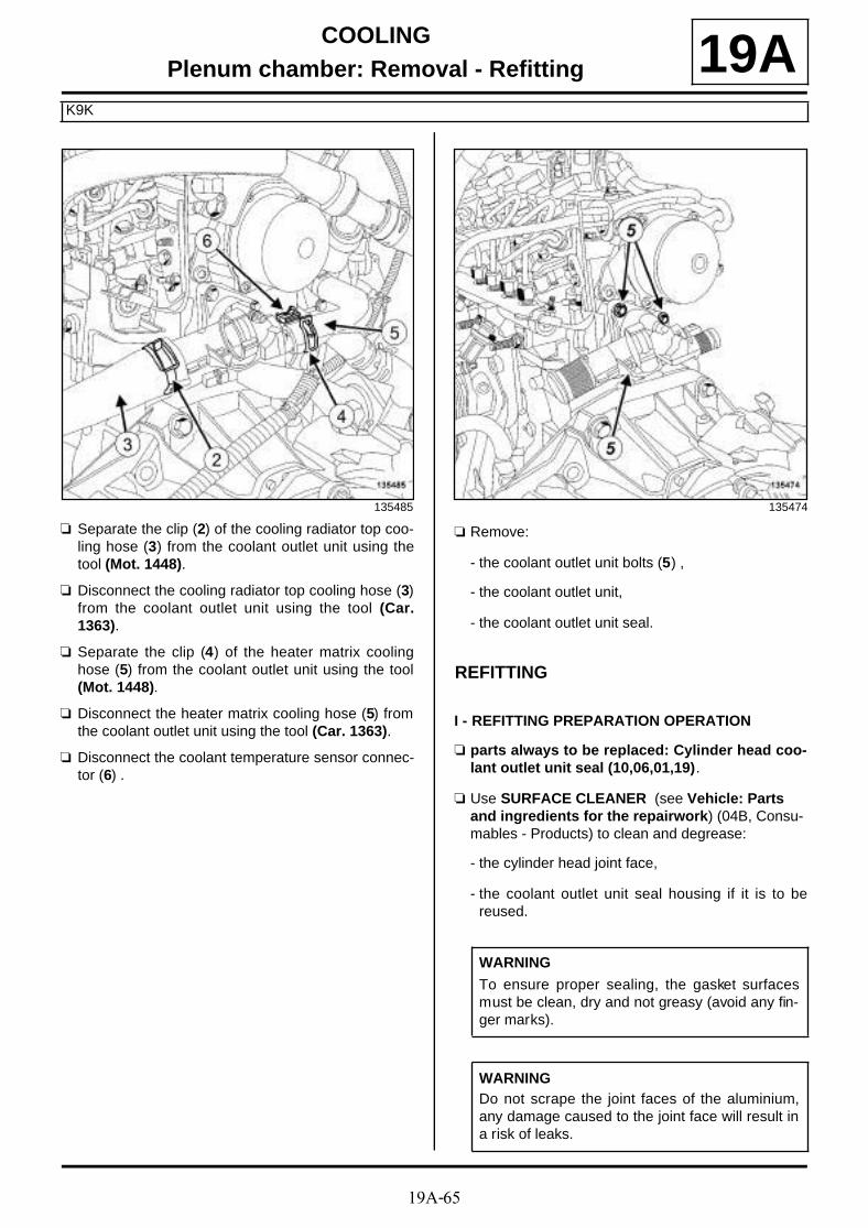
19A-65
COOLINGPlenum chamber: Removal - Refitting
K9K
19A
a Separate the clip (2) of the cooling radiator top coo-ling hose (3) from the coolant outlet unit using thetool (Mot. 1448).
a Disconnect the cooling radiator top cooling hose (3)from the coolant outlet unit using the tool (Car.1363).
a Separate the clip (4) of the heater matrix coolinghose (5) from the coolant outlet unit using the tool(Mot. 1448).
a Disconnect the heater matrix cooling hose (5) fromthe coolant outlet unit using the tool (Car. 1363).
a Disconnect the coolant temperature sensor connec-tor (6) .
a Remove:
- the coolant outlet unit bolts (5) ,
- the coolant outlet unit,
- the coolant outlet unit seal.
REFITTING
I - REFITTING PREPARATION OPERATION
a parts always to be replaced: Cylinder head coo-lant outlet unit seal (10,06,01,19).
a Use SURFACE CLEANER (see Vehicle: Parts and ingredients for the repairwork) (04B, Consu-mables - Products) to clean and degrease:
- the cylinder head joint face,
- the coolant outlet unit seal housing if it is to bereused.
135485 135474
WARNING
To ensure proper sealing, the gasket surfacesmust be clean, dry and not greasy (avoid any fin-ger marks).
WARNINGDo not scrape the joint faces of the aluminium,any damage caused to the joint face will result ina risk of leaks.
19A-66
COOLINGPlenum chamber: Removal - Refitting
K9K
19AII - REFITTING OPERATION FOR PART CONCERNED
a Refit:
- a new coolant outlet unit seal in the coolant outletunit housing,
- the coolant outlet unit.
a Torque tighten the coolant outlet unit bolts (11N.m).
a Connect:
- the coolant temperature sensor connector,
- the heater matrix cooling hose to the coolant outletunit.
a Fit the clip on the heater matrix cooling hose ontothe coolant outlet unit using the tool (Mot. 1448).
a Connect the cooling radiator top cooling hose to thecoolant outlet unit.
a Fit the clip of the cooling radiator top cooling hose onthe coolant outlet unit using the tool (Mot. 1448).
a Clip the expansion bottle bottom cooling hose on thecoolant outlet unit.
III - FINAL OPERATION
a Refit:
- the front bumper (see Front bumper: Removal -Refitting) (55A, Exterior protection),
- the engine undertray,
- the front section of the front wheel arch liners (seeFront wheel arch liner: Removal - Refitting)(55A, Exterior protection),
- the front wheels (see Wheel: Removal - Refitting)(35A, Wheels and tyres),
- the battery tray (see Battery tray: Removal - Re-fitting) (80A, Battery),
- the battery (see Battery : Removal - Refitting)(80A, Battery),
- the engine cover,
a Fill and bleed the cooling system (see 19A, Coo-ling, Cooling circuit: Draining - Refilling, page19A-17) .
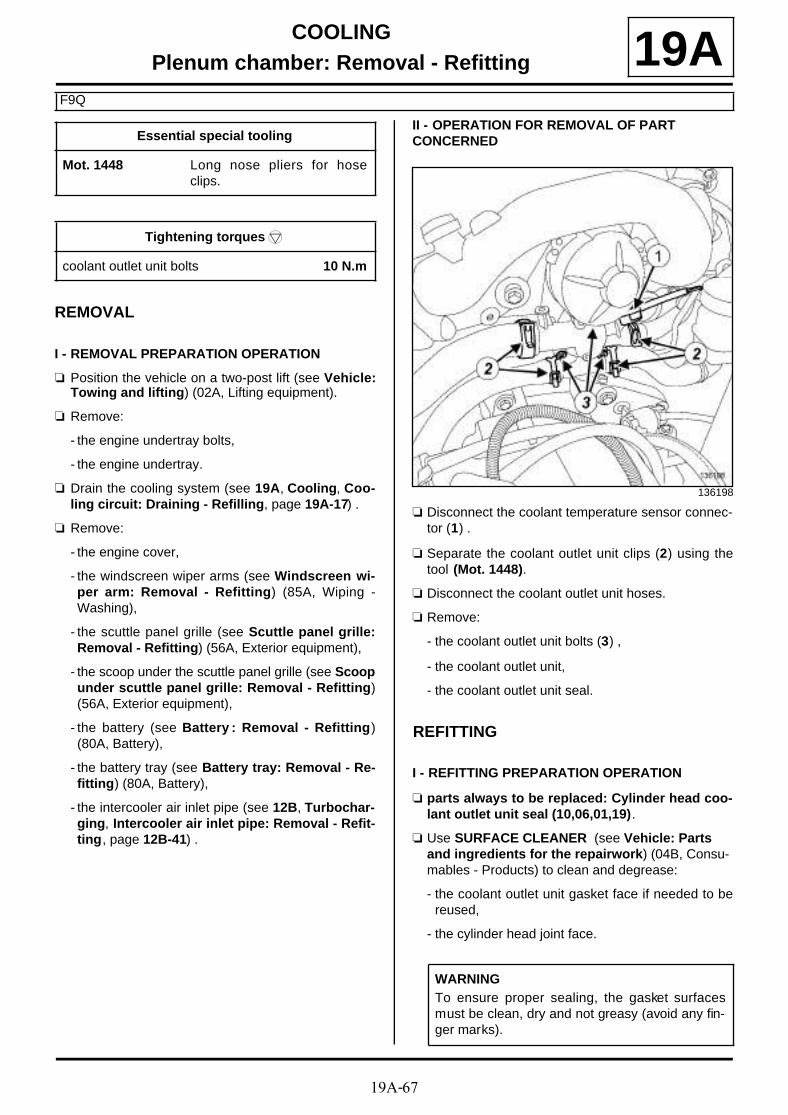
19A-67
COOLINGPlenum chamber: Removal - Refitting
F9Q
19A
REMOVAL
I - REMOVAL PREPARATION OPERATION
a Position the vehicle on a two-post lift (see Vehicle:Towing and lifting) (02A, Lifting equipment).
a Remove:
- the engine undertray bolts,
- the engine undertray.
a Drain the cooling system (see 19A, Cooling, Coo-ling circuit: Draining - Refilling, page 19A-17) .
a Remove:
- the engine cover,
- the windscreen wiper arms (see Windscreen wi-per arm: Removal - Refitting) (85A, Wiping -Washing),
- the scuttle panel grille (see Scuttle panel grille:Removal - Refitting) (56A, Exterior equipment),
- the scoop under the scuttle panel grille (see Scoopunder scuttle panel grille: Removal - Refitting)(56A, Exterior equipment),
- the battery (see Battery : Removal - Refitting)(80A, Battery),
- the battery tray (see Battery tray: Removal - Re-fitting) (80A, Battery),
- the intercooler air inlet pipe (see 12B, Turbochar-ging, Intercooler air inlet pipe: Removal - Refit-ting, page 12B-41) .
II - OPERATION FOR REMOVAL OF PART CONCERNED
a Disconnect the coolant temperature sensor connec-tor (1) .
a Separate the coolant outlet unit clips (2) using thetool (Mot. 1448).
a Disconnect the coolant outlet unit hoses.
a Remove:
- the coolant outlet unit bolts (3) ,
- the coolant outlet unit,
- the coolant outlet unit seal.
REFITTING
I - REFITTING PREPARATION OPERATION
a parts always to be replaced: Cylinder head coo-lant outlet unit seal (10,06,01,19).
a Use SURFACE CLEANER (see Vehicle: Parts and ingredients for the repairwork) (04B, Consu-mables - Products) to clean and degrease:
- the coolant outlet unit gasket face if needed to bereused,
- the cylinder head joint face.
Essential special tooling
Mot. 1448 Long nose pliers for hoseclips.
Tightening torquesm
coolant outlet unit bolts 10 N.m
136198
WARNINGTo ensure proper sealing, the gasket surfacesmust be clean, dry and not greasy (avoid any fin-ger marks).

19A-68
COOLINGPlenum chamber: Removal - Refitting
F9Q
19AII - REFITTING OPERATION FOR PART CONCERNED
a Refit:
- a new coolant outlet unit seal,
- the coolant outlet unit.
a Torque tighten the coolant outlet unit bolts (10N.m).
a Connect the coolant outlet unit hoses.
a Position the hose clips on the coolant outlet unitusing the tool (Mot. 1448).
a Connect the coolant temperature sensor connector.
III - FINAL OPERATION
a Refit:
- the intercooler air inlet pipe (see 12B, Turbochar-ging, Intercooler air inlet pipe: Removal - Refit-ting, page 12B-41) ,
- the battery tray (see Battery tray: Removal - Re-fitting) (80A, Battery),
- the battery (see Battery : Removal - Refitting)(80A, Battery),
- the scoop under the scuttle panel grille (see Scoopunder scuttle panel grille: Removal - Refitting)(56A, Exterior equipment),
- the scuttle panel grille (see Scuttle panel grille:Removal - Refitting) (56A, Exterior equipment),
- the windscreen wiper arms (see Windscreen wi-per arm: Removal - Refitting) (85A, Wiping -Washing),
- the engine cover,
- the engine undertray.
a Fill and bleed the cooling system (see 19A, Coo-ling, Cooling circuit: Draining - Refilling, page19A-17) .

19A-69
COOLINGPlenum chamber: Removal - Refitting
F4R
19A
REMOVAL
I - REMOVAL PREPARATION OPERATION
a Position the vehicle on a two-post lift (see Vehicle:Towing and lifting) (02A, Lifting equipment).
a Remove:
- the engine cover,
- the battery (see Battery : Removal - Refitting)(80A, Battery),
- the battery tray (see Battery : Removal - Refit-ting) (80A, Battery),
- the front wheels (see Wheel: Removal - Refitting)(35A, Wheels and tyres),
- the front section of the front wheel arch liners (seeFront wheel arch liner: Removal - Refitting)(55A, Exterior protection),
- the engine undertray bolts,
- the engine undertray,
- the front bumper (see Front bumper: Removal -Refitting) (55A, Exterior protection).
a Drain the cooling system (see 19A, Cooling, Coo-ling circuit: Draining - Refilling, page 19A-17) .
Essential special tooling
Mot. 1448 Long nose pliers for hoseclips.
IMPORTANT
When working in the engine compartment, takecare as the radiator fan(s) may start up unexpecte-dly (risk of being cut).
To avoid any risk of serious burns when the engine is hot:
- do not open the expansion bottle cap,
- do not drain the cooling system,
- do not open the bleed screw(s).
WARNING
When carrying out a repair that requires a completechange, it is essential to flush the circuit with cleanwater, blast compressed air through the circuit todrive out the water, fill and bleed the circuit andthen measure the effective protection.
The criteria to be met are:
- protection down to -25˚C ±±±± 2 for cold and tempe-rate countries,
- protection down to -40˚C ±±±± 2 for "extreme cold"countries.
WARNING
Before the operation, protect the electrical accesso-ries to prevent any risk of shor t circuiting and pro-tect the belts to avoid damaging them.
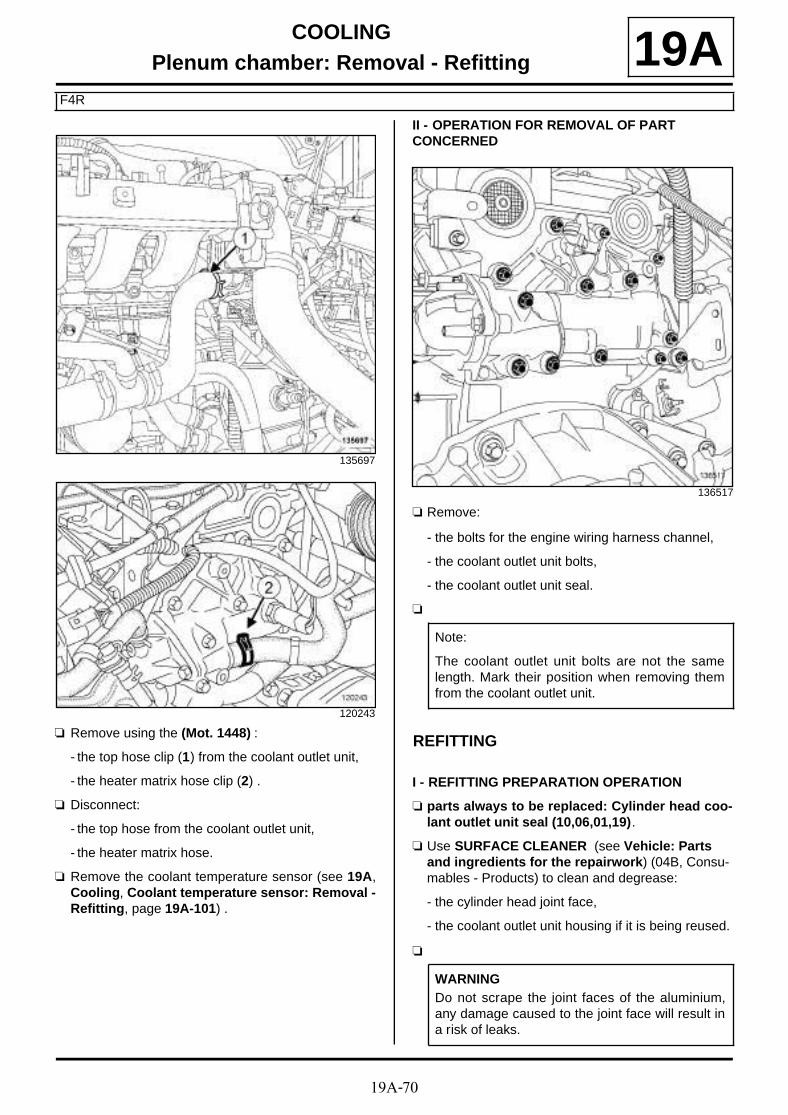
19A-70
COOLINGPlenum chamber: Removal - Refitting
F4R
19A
a Remove using the (Mot. 1448) :
- the top hose clip (1) from the coolant outlet unit,
- the heater matrix hose clip (2) .
a Disconnect:
- the top hose from the coolant outlet unit,
- the heater matrix hose.
a Remove the coolant temperature sensor (see 19A,Cooling, Coolant temperature sensor: Removal -Refitting, page 19A-101) .
II - OPERATION FOR REMOVAL OF PART CONCERNED
a Remove:
- the bolts for the engine wiring harness channel,
- the coolant outlet unit bolts,
- the coolant outlet unit seal.
a
REFITTING
I - REFITTING PREPARATION OPERATION
a parts always to be replaced: Cylinder head coo-lant outlet unit seal (10,06,01,19).
a Use SURFACE CLEANER (see Vehicle: Parts and ingredients for the repairwork) (04B, Consu-mables - Products) to clean and degrease:
- the cylinder head joint face,
- the coolant outlet unit housing if it is being reused.
a
135697
120243
136517
Note:
The coolant outlet unit bolts are not the samelength. Mark their position when removing themfrom the coolant outlet unit.
WARNINGDo not scrape the joint faces of the aluminium,any damage caused to the joint face will result ina risk of leaks.

19A-71
COOLINGPlenum chamber: Removal - Refitting
F4R
19Aa
If replacing the coolant outlet unit
a Remove:
- the bleed screw (3) ,
- the metal tube (4) ,
- the thermostat unit bolts (5) ,
- the thermostat,
- the thermostat seal.
a Use SURFACE CLEANER (see Vehicle: Partsand ingredients for the repairwork) (04B, Consu-mables - Products) to clean and degrease the jointface of the thermostat unit.
a Refit:
- the metal tube,
- the bleed screw,
- the thermostat fitted with a new seal,
- the thermostat unit,
- the thermostat unit bolts.
II - REFITTING OPERATION FOR PART CONCERNED
a Refit:
- a new seal on the coolant outlet unit,
- the coolant outlet unit.
III - FINAL OPERATION
a Tighten the following in order:
- the coolant outlet unit bolts from (3) to (9) ,
- the coolant outlet unit bolts (1) then (2) .
a Refit the coolant temperature sensor (see 19A,Cooling, Coolant temperature sensor: Removal -Refitting, page 19A-101) .
a Connect:
- the top hose on the coolant outlet unit,
- the heater matrix hose.
a Using the (Mot. 1448), fit:
- the heater matrix hose clip,
- the top hose clip of the coolant outlet unit.
a Fill and bleed the cooling system (see 19A, Coo-ling, Cooling circuit: Draining - Refilling, page19A-17) .
a Refit:
- the front bumper (see Front bumper: Removal -Refitting) (55A, Exterior protection).
WARNING
To ensure proper sealing, the gasket surfacesmust be clean, dry and not greasy (avoid any fin-ger marks).
121701
WARNING
To ensure proper sealing, the gasket surfacesmust be clean, dry and not greasy (avoid any fin-ger marks).
136517

19A-72
COOLINGPlenum chamber: Removal - Refitting
F4R
19A- the engine undertray,
- the front section of the front wheel arch liners (seeFront wheel arch liner: Removal - Refitting)(55A, Exterior protection),
- the front wheels (see Wheel: Removal - Refitting)(35A, Wheels and tyres),
- the battery tray (see Battery : Removal - Refit-ting) (80A, Battery),
- the battery (see Battery : Removal - Refitting)(80A, Battery),
- the engine cover.

19A-73
COOLINGEngine cooling fan assembly: Removal - Refitting
K4M
19A
REMOVAL
I - REMOVAL PREPARATION OPERATION
a Position the vehicle on a two-post lift (see Vehicle:Towing and lifting) (02A, Lifting equipment).
a Disconnect the battery (see Battery: Removal - Re-fitting) (80A, Battery).
a Remove:
- the engine undertray bolts,
- the engine undertray.
II - OPERATION FOR REMOVAL OF PART CONCERNED
a Unclip the cooling hoses from the engine cooling fanassembly at (1) .
a Move the cooling hoses away from the engine coo-ling fan assembly.
IMPORTANT
When working in the engine compartment, takecare as the radiator fan(s) may start up unexpecte-dly (risk of being cut).
To avoid any risk of serious burns when the engine is hot:
- do not open the expansion bottle cap,
- do not drain the cooling system,
- do not open the bleed screw(s).
135930
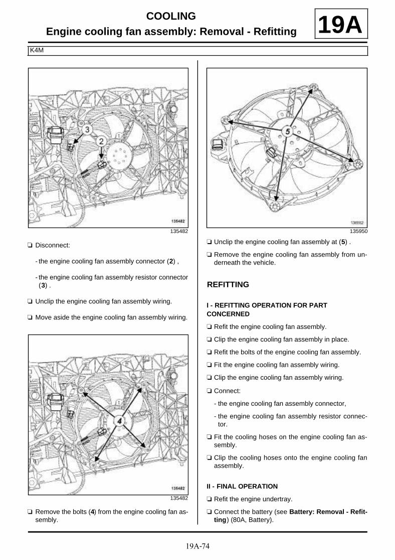
19A-74
COOLINGEngine cooling fan assembly: Removal - Refitting
K4M
19A
a Disconnect:
- the engine cooling fan assembly connector (2) ,
- the engine cooling fan assembly resistor connector(3) .
a Unclip the engine cooling fan assembly wiring.
a Move aside the engine cooling fan assembly wiring.
a Remove the bolts (4) from the engine cooling fan as-sembly.
a Unclip the engine cooling fan assembly at (5) .
a Remove the engine cooling fan assembly from un-derneath the vehicle.
REFITTING
I - REFITTING OPERATION FOR PART CONCERNED
a Refit the engine cooling fan assembly.
a Clip the engine cooling fan assembly in place.
a Refit the bolts of the engine cooling fan assembly.
a Fit the engine cooling fan assembly wiring.
a Clip the engine cooling fan assembly wiring.
a Connect:
- the engine cooling fan assembly connector,
- the engine cooling fan assembly resistor connec-tor.
a Fit the cooling hoses on the engine cooling fan as-sembly.
a Clip the cooling hoses onto the engine cooling fanassembly.
II - FINAL OPERATION
a Refit the engine undertray.
a Connect the battery (see Battery: Removal - Refit-ting) (80A, Battery).
135482
135482
135950
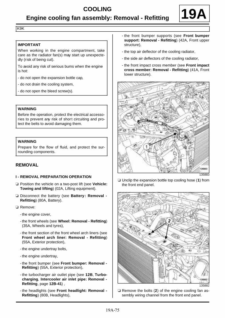
19A-75
COOLINGEngine cooling fan assembly: Removal - Refitting
K9K
19A
REMOVAL
I - REMOVAL PREPARATION OPERATION
a Position the vehicle on a two-post lift (see Vehicle:Towing and lifting) (02A, Lifting equipment).
a Disconnect the battery (see Battery : Removal -Refitting) (80A, Battery).
a Remove:
- the engine cover,
- the front wheels (see Wheel: Removal - Refitting)(35A, Wheels and tyres),
- the front section of the front wheel arch liners (seeFront wheel arch liner: Removal - Refitting)(55A, Exterior protection),
- the engine undertray bolts,
- the engine undertray,
- the front bumper (see Front bumper: Removal -Refitting) (55A, Exterior protection),
- the turbocharger air outlet pipe (see 12B, Turbo-charging, Intercooler air inlet pipe: Removal -Refitting, page 12B-41) ,
- the headlights (see Front headlight: Removal -Refitting) (80B, Headlights),
- the front bumper supports (see Front bumpersupport: Removal - Refitting) (42A, Front upperstructure),
- the top air deflector of the cooling radiator,
- the side air deflectors of the cooling radiator,
- the front impact cross member (see Front impactcross member: Removal - Refitting) (41A, Frontlower structure).
a Unclip the expansion bottle top cooling hose (1) fromthe front end panel.
a Remove the bolts (2) of the engine cooling fan as-sembly wiring channel from the front end panel.
IMPORTANT
When working in the engine compartment, takecare as the radiator fan(s) may start up unexpecte-dly (risk of being cut).
To avoid any risk of serious burns when the engine is hot:
- do not open the expansion bottle cap,
- do not drain the cooling system,
- do not open the bleed screw(s).
WARNING
Before the operation, protect the electrical accesso-ries to prevent any risk of shor t circuiting and pro-tect the belts to avoid damaging them.
WARNING
Prepare for the flow of fluid, and protect the sur-rounding components.
135883
135882

19A-76
COOLINGEngine cooling fan assembly: Removal - Refitting
K9K
19A
a Remove from the front end panel:
- the clips (3) ,
- the upper bolts (4) .
a Remove the lower bolts (5) from the front end panel.
a Tilt the front end panel slightly towards the front ofthe vehicle.
II - OPERATION FOR REMOVAL OF PART CONCERNED
a Disconnect:
- the fan assembly connector (6) ,
- the fan assembly resistor connector (7) .
a Unclip the fan assembly wiring from the fan assem-bly (8) .
a Remove:
- the bolts (9) from the fan assembly,
- the fan assembly.
135719
135881
135482
135466

19A-77
COOLINGEngine cooling fan assembly: Removal - Refitting
K9K
19AREFITTING
I - REFITTING OPERATION FOR PART CONCERNED
a Refit the fan assembly on the front end panel.
a Clip the fan assembly wiring onto the fan assembly.
a Connect the following connectors:
- the fan assembly,
- the fan assembly resistor.
II - FINAL OPERATION
a Fit the front end panel.
a Refit:
- the lower bolts from the front end panel,
- the front end panel upper bolts,
- the front end panel clips.
- the bolts of the engine cooling fan assembly wiringchannel on the front end panel.
a Clip the expansion bottle top cooling hose onto thefront end panel.
a Refit:
- the front impact cross member (see Front impactcross member: Removal - Refitting) (41A, Frontlower structure),
- the side air deflectors on the radiator,
- the top air deflector,
- the front right-hand bumper mountings (see Frontbumper support: Removal - Refitting) (42A,Front upper structure).
- the headlights (see Front headlight: Removal -Refitting) (80B, Headlights),
- the turbocharger air outlet pipe (see 12B, Turbo-charging, Intercooler air inlet pipe: Removal -Refitting, page 12B-41) ,
- the front bumper (see Front bumper: Removal -Refitting) (55A, Exterior protection),
- the engine undertray,
- the front section of the front wheel arch liners (seeFront wheel arch liner: Removal - Refitting)(55A, Exterior protection),
- the front wheels (see Wheel: Removal - Refitting)(35A, Wheels and tyres),
- the engine cover.
a Connect the battery (see Battery : Removal - Refit-ting) (80A, Battery).

19A-78
COOLINGEngine cooling fan assembly: Removal - Refitting
F9Q
19AREMOVAL
I - REMOVAL PREPARATION OPERATION
a Position the vehicle on a two-post lift (see Vehicle:Towing and lifting) (02A, Lifting equipment).
a Disconnect the battery (see Battery: Removal - Re-fitting) (80A, Battery).
a Remove:
- the engine cover,
- the engine undertray bolts,
- the engine undertray,
- the front wheels (see Wheel: Removal - Refitting)(35A, Wheels and tyres),
- the front section of the front wheel arch liners (seeFront wheel arch liner: Removal - Refitting)(55A, Exterior protection),
- the front bumper (see Front bumper: Removal -Refitting) (55A, Exterior protection),
- the headlights (see Front headlight: Removal -Refitting) (80B, Headlights),
- the front bumper supports (see Front bumpersupport: Removal - Refitting) (42A, Front upperstructure).
- the front impact cross member (see Front impactcross member: Removal - Refitting) (41A, Frontlower structure),
a Remove:
- the bolts (1) of the engine wiring channel,
- the bonnet catch (see Bonnet latch: Removal -Refitting) (52A, Non-side opening element mecha-nisms).
a Remove the front end panel bolts (2) .
a Tilt the front end panel.
a Remove the intercooler outlet air outlet pipe (see12B, Turbocharging, Intercooler air outlet pipe:Removal - Refitting, page 12B-56) .
135647
135645
135646

19A-79
COOLINGEngine cooling fan assembly: Removal - Refitting
F9Q
19AII - OPERATION FOR REMOVAL OF PART CONCERNED
a Disconnect:
- the fan assembly connector (3) ,
- the fan assembly resistor connector (4) .
a Remove:
- the bolts (5) from the fan assembly,
- the fan assembly.
REFITTING
I - REFITTING OPERATION FOR PART CONCERNED
a Refit the fan assembly.
a Connect:
- the fan assembly resistor connector,
- the motor-driven fan assembly connector.
II - FINAL OPERATION
a Refit:
- a new intercooler air outlet pipe (see 12B, Turbo-charging, Intercooler air outlet pipe: Removal -Refitting, page 12B-56) ,
- the front end panel,
- the bonnet catch (see Bonnet latch: Removal -Refitting) (52A, Non-side opening element mecha-nisms),
- the bolts of the engine wiring channel.
- the front impact cross member (see Front impactcross member: Removal - Refitting) (41A, Frontupper structure),
- the front bumper mountings (see Front bumpersupport: Removal - Refitting) (42A, Front upperstructure),
- the headlights (see Front headlight: Removal -Refitting) (80B, Headlights),
- the front bumper (see Front bumper: Removal -Refitting) (55A, Exterior protection),
- the front section of the front wheel arch liners (seeFront wheel arch liner: Removal - Refitting)(55A, Exterior protection),
- the front wheels (see Wheel: Removal - Refitting)(35A, Wheels and tyres),
- the engine undertray,
- the engine cover.
a Connect the battery (see Battery: Removal - Refit-ting) (80A, Battery).
135992
135466

19A-80
COOLINGEngine cooling fan assembly: Removal - Refitting
F4R
19Aa
REMOVAL
I - REMOVAL PREPARATION OPERATION
a Position the vehicle on a two-post lift (see Vehicle:Towing and lifting) (02A, Lifting equipment).
a Disconnect the battery (see Battery : Removal -Refitting) (80A, Battery).
a Remove:
- the engine cover,
- the engine undertray bolts,
- the engine undertray,
- the front wheels (see Wheel: Removal - Refitting)(35A, Wheels and tyres),
- the front section of the front wheel arch liners (seeFront wheel arch liner: Removal - Refitting)(55A, Exterior protection),
- the front bumper (see Front bumper: Removal -Refitting) (55A, Exterior protection),
- the upper air deflector,
- the side air deflectors,
- the accessories belt (see 11A, Top and front ofengine, Accessories belt: Removal - Refitting,page 11A-7) ,
- the headlights (see Front headlight: Removal -Refitting) (80B, Headlights),
- the front bumper supports (see Front bumpersupport: Removal - Refitting) (42A, Front upperstructure),
- the audible warning (see Horn: Removal - Refit-ting) (82B, Horn),
- the front impact cross member (see Front impactcross member: Removal - Refitting) (41A, Frontlower structure),
- the bonnet catch (see Bonnet latch: Removal -Refitting) (52A, Non-side opening element mecha-nisms).
a Remove the bolts (1) of the wiring channel from theengine cooling fan assembly.
a Remove:
- the upper bolts (2) from the front end panel,
- the front end panel clips (3) .
IMPORTANT
When working in the engine compartment, takecare as the radiator fan(s) may start up unexpec-tedly (risk of being cut).
To avoid any risk of serious burns when the engine is hot:
- do not open the expansion bottle cap,
- do not drain the cooling system,
- do not open the bleed screw(s).
135736
135719

19A-81
COOLINGEngine cooling fan assembly: Removal - Refitting
F4R
19A
a Remove the lower bolts (4) from the front end panel.
a Tilt the front end panel slightly towards the front ofthe vehicle.
a Remove the intercooler outlet air outlet pipe (see12B, Turbocharging, Intercooler air outlet pipe:Removal - Refitting, page 12B-56) .
II - OPERATION FOR REMOVAL OF PART CONCERNED
a Disconnect:
- the fan assembly connector (5) ,
- the fan assembly resistor connector (6) .
a Unclip the fan assembly wiring from the fan assem-bly at (7) .
a Remove:
- the bolts (8) from the fan assembly,
- the fan assembly.
135296
135482
135994

19A-82
COOLINGEngine cooling fan assembly: Removal - Refitting
F4R
19AREFITTING
I - REFITTING OPERATION FOR THE PART
a Refit the fan assembly.
a Clip the fan assembly wiring onto the fan assembly.
a Connect:
- the fan assembly resistor connector,
- the motor-driven fan assembly connector.
II - FINAL OPERATION
a Refit the intercooler air outlet pipe (see 12B, Turbo-charging, Intercooler air outlet pipe: Removal -Refitting, page 12B-56) .
a Fit the front end panel.
a Refit:
- the lower bolts from the front end panel,
- the front end panel clips,
- the front end panel upper bolts,
- the bolts of the wiring channel of the engine coolingfan assembly,
- the bonnet catch (see Bonnet latch: Removal -Refitting) (52A, Non-side opening element mecha-nisms),
- the front impact cross member (see Front impactcross member: Removal - Refitting) (41A, Frontlower structure),
- the audible warning (see Horn: Removal - Refit-ting) (82B, Horn),
- the front bumper supports (see Front bumpersupport: Removal - Refitting) (42A, Front upperstructure),
- the headlights (see Front headlight: Removal -Refitting) (80B, Headlights),
- the accessories belt (see 11A, Top and front ofengine, Accessories belt: Removal - Refitting,page 11A-7) ,
- the side air deflectors,
- the upper air deflector,
- the front bumper (see Front bumper: Removal -Refitting) (55A, Exterior protection),
- the front section of the front wheel arch liners (seeFront wheel arch liner: Removal - Refitting)(55A, Exterior protection),
- the front wheels (see Wheel: Removal - Refitting)(35A, Wheels and tyres),
- the engine undertray,
- the engine cover.
a Connect the battery (see Battery : Removal - Refit-ting) (80A, Battery).
a Adjust the headlights (see Front headlight: Adjus-ting) (80B, Headlights).

19A-83
COOLINGWater pump inlet pipe: Removal - Refitting
K4M
19A
REMOVAL
I - REMOVAL PREPARATION OPERATION
a Position the vehicle on a two-post lift (see Vehicle:Towing and lifting) (02A, Lifting equipment).
a Disconnect the battery (see Battery: Removal - Re-fitting) (80A, Battery).
a Remove:
- the engine cover,
- the front wheels (see Wheel: Removal - Refitting)(35A, Wheels and tyres),
- the front section of the front wheel arch liners (seeFront wheel arch liner: Removal - Refitting)(55A, Exterior protection),
- the engine undertray bolts,
- the engine undertray,
- the front bumper (see Front bumper: Removal -Refitting) (55A, Exterior protection).
a Drain the cooling system (see 19A, Cooling, Coo-ling circuit: Draining - Refilling, page 19A-17) .
a Remove:
- the alternator strut nut (1) from the cylinder block,
- the alternator strut bolt (2) from the alternator,
- the alternator strut,
- the washer located behind the bracket.
a Remove:
- the dipstick,
- the dipstick guide bolt (3) from the lifting eye,
- the dipstick guide.
Essential special tooling
Mot. 1202-02 Pliers for small hose clips.
Mot. 1202-01 Pliers for large hose clips.
Mot. 1448 Long nose pliers for hoseclips.
Tightening torquesm
coolant pump inlet pipebolt
22 N.m
coolant pump inlet pipebolts
25 N.m
bolt of the alternatorstrut on the alternator
25 N.m
alternator strut nut onthe cylinder block
25 N.m
dipstick guide tube bolt 10 N.m
dipstick guide tube bolts 10 N.m
K4M, and 848
135727
136454

19A-84
COOLINGWater pump inlet pipe: Removal - Refitting
K4M
19A
a Remove:
- the dipstick,
- the dipstick guide bolts (4) from the injector holdersupport,
- the dipstick guide,
- the oil pressure sensor (see 10A, Engine and cy-linder block assembly, Oil pressure sensor: Re-moval - Refitting, page 10A-64) .
II - OPERATION FOR REMOVAL OF PART CONCERNED
a Unclip the alternator wiring (5) .
a Using the (Mot. 1202-02) or (Mot. 1202-01) or (Mot. 1448) remove:
- the heater matrix hose clip (6) ,
- the cooling radiator bottom hose clip (7) .
a Disconnect the following from the coolant pump inlet pipe:
- the heater matrix hose,
- the cooling radiator bottom hose.
a Remove:
- the bolt (8) from the coolant pump inlet pipe,
- the coolant pump inlet pipe.
K4M, and 858 or 866
136574
K4M, and 848
135254

19A-85
COOLINGWater pump inlet pipe: Removal - Refitting
K4M
19A
a Using the (Mot. 1202-02) or (Mot. 1202-01) or (Mot. 1448) remove:
- the heater matrix hose clip (9) ,
- the cooling radiator bottom hose clip (10) .
a Disconnect the following from the coolant pump inlet pipe:
- the heater matrix hose,
- the cooling radiator bottom hose.
a Remove:
- the bolts (11) and (12) from the coolant pump inletpipe,
- the coolant pump inlet pipe.
K4M, and 858 or 866
136576
136572
136577

19A-86
COOLINGWater pump inlet pipe: Removal - Refitting
K4M
19AREFITTING
I - REFITTING PREPARATION OPERATION
a parts always to be replaced: seal between coo-lant pump inlet pipe and coolant pump (10,06,01,22).
II - REFITTING OPERATION FOR PART CONCERNED
a Refit the coolant pump inlet pipe fitted with a newseal.
a Torque tighten the coolant pump inlet pipe bolt(22 N.m).
a Torque tighten the coolant pump inlet pipe bolts(25 N.m).
III - FINAL OPERATION
a Connect the following to the coolant pump inlet pipe:
- the heater matrix hose,
- the cooling radiator bottom hose.
a Using the (Mot. 1202-02) or (Mot. 1202-01) or (Mot. 1448) fit:
- the heater matrix hose clip,
- the cooling radiator bottom hose clip.
a Clip the alternator wiring.
a Refit:
- the washer located behind the alternator bracket,
- the alternator strut,
- the bolt mounting the strut on the alternator,
- the alternator strut nut on the cylinder block.
a Tighten to torque:
- the bolt of the alternator strut on the alternator(25 N.m),
- the alternator strut nut on the cylinder block (25N.m).
a Refit the dipstick guide.
a Torque tighten the dipstick guide tube bolt (10N.m).
a Torque tighten the dipstick guide tube bolts (10N.m).
a Refit the oil pressure sensor (see 10A, Engine andcylinder block assembly, Oil pressure sensor:Removal - Refitting, page 10A-64) .
a Refit:
- the dipstick,
- the front bumper (see Front bumper: Removal -Refitting) (55A, Exterior protection),
- the engine undertray,
- the front section of the front wheel arch liners (seeFront wheel arch liner: Removal - Refitting)(55A, Exterior protection),
- the front wheels (see Wheel: Removal - Refitting)(35A, Wheels and tyres),
- the engine cover.
a Connect the battery (see Battery: Removal - Refit-ting) (80A, Battery).
a Fill and bleed the cooling system (see 19A, Coo-ling, Cooling circuit: Draining - Refilling, page19A-17) .
K4M, and 848
K4M, and 858 or 866
K4M, and 848
K4M, and 848
K4M, and 858 or 866

19A-87
COOLINGWater pump inlet pipe: Removal - Refitting
K9K
19A
REMOVAL
I - REMOVAL PREPARATION OPERATION
a Position the vehicle on a two-post lift (see Vehicle:Towing and lifting) (02A, Lifting equipment).
a Remove:
- the engine cover,
- the front wheels (see Wheel: Removal - Refitting)(35A, Wheels and tyres),
- the front section of the front wheel arch liners (seeFront wheel arch liner: Removal - Refitting)(55A, Exterior protection),
- the engine undertray bolts,
- the engine undertray,
- the front bumper (see Front bumper: Removal -Refitting) (55A, Exterior protection).
a Drain:
- the cooling system (see 19A, Cooling, Coolingcircuit: Draining - Refilling, page 19A-17) ,
- the refrigerant circuit using a refrigerant chargingstation (see Coolant circuit Draining - Refilling)(62A, Air conditioning).
a Remove the oil-water heat exchanger (see 10A, En-gine and cylinder block assembly, Exchanger:Removal - Refitting, page 10A-55) .
II - OPERATION FOR REMOVAL OF PART CONCERNED
a Remove:
- the bolt (1) from the coolant pump inlet pipe,
- the coolant pump inlet pipe,
- the coolant pump inlet pipe seal.
Essential equipment
refrigerant charging station
Tightening torquesm
coolant pump inlet pipebolt
25 N.m
IMPORTANT
Wear leaktight gloves (Nitrile type) for this opera-tion.
IMPORTANT
Wear heat protective gloves during the operation.
IMPORTANT
The circuits are designed to be pressurised, so becareful at high temperatures (risk of serious burns).
Do not remove the cap from the expansion bottlewhile the engine is hot.
Take care when carrying out a repair under the bon-net, as the radiator fan(s) may start to operatewithout warning.
Do not open the bleed screw(s) with the engine run-ning.
WARNING
Prepare for the flow of fluid, and protect the sur-rounding components.
135467

19A-88
COOLINGWater pump inlet pipe: Removal - Refitting
K9K
19AREFITTING
I - REFITTING PREPARATION OPERATION
a parts always to be replaced: seal between coo-lant pump inlet pipe and coolant pump (10,06,01,22).
a parts always to be replaced: refrigerant pipe seal(30,02,02,52)
a Use SURFACE CLEANER (see Vehicle: Parts and ingredients for the repairwork) (04B, Consu-mables - Products) to clean and degrease:
- the housing of the seal on the coolant pump inletpipe if it is to be reused,
- the seal housing in the cylinder block.
II - REFITTING OPERATION FOR PART CONCERNED
a Refit the coolant pump inlet pipe fitted with a newseal.
a Torque tighten the coolant pump inlet pipe bolt(25 N.m).
III - FINAL OPERATION
a Refit:
- the coolant-oil heat exchanger (see 10A, Engineand cylinder block assembly, Exchanger: Re-moval - Refitting, page 10A-55) ,
- the front bumper (see Front bumper: Removal -Refitting) (55A, Exterior protection),
- the engine undertray,
- the front section of the front wheel arch liners (seeFront wheel arch liner: Removal - Refitting)(55A, Exterior protection),
- the front wheels (see Wheel: Removal - Refitting)(35A, Wheels and tyres),
- the engine cover.
a Fill and bleed the cooling system (see 19A, Coo-ling, Cooling circuit: Draining - Refilling, page19A-17) .
Perform the following operations:
- fill and bleed the cooling circuit (see 19A, Cooling,Cooling circuit: Draining - Refilling, page 19A-17) ,
- fill the refrigerant circuit (see Coolant circuit Drai-ning - Refilling) (62A, Air conditioning).

19A-89
COOLINGWater pump inlet pipe: Removal - Refitting
F4R
19A
REMOVAL
I - REMOVAL PREPARATION OPERATION
a Position the vehicle on a two-post lift (see Vehicle:Towing and lifting) (02A, Lifting equipment).
a Disconnect the battery (see Battery : Removal -Refitting) (80A, Battery).
a Remove:
- the engine cover,
- the engine undertray bolts,
- the engine undertray.
a Perform the following operations:
- drain the refrigerant circuit using a refrigerantcharging station (see Coolant circuit Draining -Refilling) (62A, Air conditioning),
- drain the cooling system (see 19A, Cooling, Coo-ling circuit: Draining - Refilling, page 19A-17) .
a Remove:
- the front wheels (see Wheel: Removal - Refitting)(35A, Wheels and tyres),
- the front section of the front wheel arch liners (seeFront wheel arch liner: Removal - Refitting)(55A, Exterior protection),
- the front bumper (see Front bumper: Removal -Refitting) (55A, Exterior protection),
- the accessories belt (see 11A, Top and front ofengine, Accessories belt: Removal - Refitting,page 11A-7) ,
- the alternator (see 16A, Starting - Charging, Al-ternator: Removal - Refitting, page 16A-1) ,
- the air conditioning compressor (see Compressor:Removal - Refitting) (62A, Air conditioning),
- the multifunction support (see 10A, Engine andcylinder block assembly, Multifunction sup-port: Removal - Refitting, page 10A-84) .
II - OPERATION FOR REMOVAL OF PART CONCERNED
a Remove the hose clip on the coolant pump inlet pipeusing the tool (Mot. 1448).
a Disconnect the hose from the coolant pump inlet pi-pe.
a Remove:
- the coolant pump inlet pipe bolt (1) on the cylinderblock,
- the coolant pump inlet pipe,
Essential special tooling
Mot. 1448 Long nose pliers for hoseclips.
Essential equipment
refrigerant charging station
Tightening torquesm
coolant pump inlet pipeoffset bolts on the cylin-der block
10 N.m
coolant pump inlet pipebolt on the cylinderblock
38 N.m
IMPORTANT
When working in the engine compartment, takecare as the radiator fan(s) may start up unexpecte-dly (risk of being cut).
To avoid any risk of serious burns when the engine is hot:
- do not open the expansion bottle cap,
- do not drain the cooling system,
- do not open the bleed screw(s).
121616

19A-90
COOLINGWater pump inlet pipe: Removal - Refitting
F4R
19A- the coolant pump inlet pipe seal.
a Remove:
- the coolant pump inlet pipe offset bolt (2) on the cy-linder block,
- the coolant pump inlet pipe offset,
- the coolant pump inlet pipe offset seal.
REFITTING
I - REFITTING PREPARATION OPERATION
a parts always to be replaced: seal between coo-lant pump inlet pipe and coolant pump inletunion (10,06,01,23).
a parts always to be replaced: seal between coo-lant pump inlet pipe and coolant pump (10,06,01,22).
a Use SURFACE CLEANER (see Vehicle: Parts and ingredients for the repairwork) (04B, Consu-mables - Products) to clean and degrease:
- the coolant pump inlet pipe seal mating face if it isbeing reused,
- the coolant pump inlet pipe seal mating face if it isbeing reused,
- the cylinder block gasket face.
II - REFITTING OPERATION FOR PART CONCERNED
a Refit:
- the coolant pump inlet pipe offset fitted with a newseal,
- the coolant pump inlet pipe offset bolt on the cylin-der block.
a Torque tighten the coolant pump inlet pipe offsetbolts on the cylinder block (10 N.m).
a Refit:
- the coolant pump inlet pipe fitted with a new seal.
- the coolant pump inlet pipe bolt on the cylinderblock.
a Torque tighten the coolant pump inlet pipe bolt onthe cylinder block (38 N.m).
a Connect the hose to the coolant pump inlet pipe.
a Fit the hose clip on the coolant pump inlet pipe usingthe tool (Mot. 1448).
III - FINAL OPERATION
a Refit:
- the multifunction support (see 10A, Engine andcylinder block assembly, Multifunction sup-port: Removal - Refitting, page 10A-84) ,
- the air conditioning compressor (see Compressor:Removal - Refitting) (62A, Air conditioning),
- the alternator (see 16A, Starting - Charging, Al-ternator: Removal - Refitting, page 16A-1) ,
- the accessories belt (see 11A, Top and front ofengine, Accessories belt: Removal - Refitting,page 11A-7) ,
- the front bumper (see Front bumper: Removal -Refitting) (55A, Exterior protection),
- the front section of the front wheel arch liners (seeFront wheel arch liner: Removal - Refitting)(55A, Exterior protection),
- the front wheels (see Wheel: Removal - Refitting)(35A, Wheels and tyres).
a Perform the following operations:
- fill the refrigerant circuit using a refrigerant char-ging station (see Coolant circuit Draining - Re-filling) (62A, Air conditioning).
- fill and bleed the coolant circuit (see 19A, Cooling,Cooling circuit: Draining - Refilling, page 19A-17) .
121617

19A-91
COOLINGWater pump inlet pipe: Removal - Refitting
F4R
19Aa Refit:
- the engine cover,
- the engine undertray.
a Connect the battery (see Battery : Removal - Refit-ting) (80A, Battery).

19A-92
COOLINGWater pump inlet pipe: Removal - Refitting
F9Q
19A
REMOVAL
I - REMOVAL PREPARATION OPERATION
a Position the vehicle on a two-post lift (see Vehicle:Towing and lifting) (02A, Lifting equipment).
a Disconnect the battery (see Battery : Removal -Refitting) (80A, Battery).
a Remove:
- the engine cover,
- the engine undertray bolts,
- the engine undertray.
a Drain:
- the refrigerant circuit using a refrigerant chargingstation (see Coolant circuit Draining - Refilling)(62A, Air conditioning),
- the cooling system (see 19A, Cooling, Coolingcircuit: Draining - Refilling, page 19A-17) .
a Remove:
- the front wheels (see Wheel: Removal - Refitting)(35A, Wheels and tyres),
- the front section of the front wheel arch liners (seeFront wheel arch liner: Removal - Refitting)(55A, Exterior protection),
- the front bumper (see Front bumper: Removal -Refitting) (55A, Exterior protection),
- the front impact cross member (see Front impactcross member: Removal - Refitting) (41A, Frontlower structure),
- the headlights (see Front headlight: Removal -Refitting) (80B, Headlights),
- the front bumper supports (see Front bumpersupport: Removal - Refitting) (42A, Front upperstructure),
- the accessories belt (see 11A, Top and front ofengine, Accessories belt: Removal - Refitting,page 11A-7) .
a Remove:
- the bolts (1) of the engine wiring channel,
- the bonnet catch (see Bonnet latch: Removal -Refitting) (52A, Non-side opening element mecha-nisms).
Essential special tooling
Mot. 1448 Long nose pliers for hoseclips.
Essential equipment
refrigerant charging station
Tightening torquesm
coolant pump inlet unionbolts
13 N.m
coolant pump inlet pipebolt
38 N.m
IMPORTANT
When working in the engine compartment, takecare as the radiator fan(s) may start up unexpecte-dly (risk of being cut).
To avoid any risk of serious burns when the engine is hot:
- do not open the expansion bottle cap,
- do not drain the cooling system,
- do not open the bleed screw(s).
135647

19A-93
COOLINGWater pump inlet pipe: Removal - Refitting
F9Q
19A
a Remove the front end panel bolts (2) .
a Tilt the front end panel.
a Remove:
- the intercooler air outlet pipe (see 12B, Turbo-charging, Intercooler air outlet pipe: Removal -Refitting, page 12B-56) ,
- the alternator (see 16A, Starting - Charging, Al-ternator: Removal - Refitting, page 16A-1) ,
- the compressor (see Compressor: Removal - Re-fitting) (62A, Air conditioning),
- the multifunction support (see 10A, Engine andcylinder block assembly, Multifunction sup-port: Removal - Refitting, page 10A-84) .
II - OPERATION FOR REMOVAL OF PART CONCERNED
a Remove the clip (3) on the coolant pump inlet pipehose using the tool (Mot. 1448).
a Disconnect the hose from the coolant pump inlet pi-pe.
135645
135646
115619

19A-94
COOLINGWater pump inlet pipe: Removal - Refitting
F9Q
19A
a Remove:
- the coolant pump inlet pipe bolt (4) on the cylinderblock,
- the coolant pump inlet pipe,
- the coolant pump inlet pipe seal.
a Remove:
- the bolts (5) from the coolant pump inlet union,
- the coolant pump inlet union,
- the coolant pump inlet union seal.
REFITTING
I - REFITTING PREPARATION OPERATION
a Use SURFACE CLEANER (see Vehicle: Parts and ingredients for the repairwork) (04B, Consu-mables - Products) to clean and degrease:
- the mating face of the coolant pump inlet pipe sealon the coolant pump inlet pipe in case of reuse,
- the mating faces of the coolant pump inlet pipe sealif it is being reused,
- the cylinder block gasket face.
a parts always to be replaced: seal between coo-lant pump inlet pipe and coolant pump inletunion (10,06,01,23),
parts always to be replaced: seal between coo-lant pump inlet union and coolant pump (10,06,01,24),
parts always to be replaced: Intercooler air out-let pipe (10,09,04,03).
II - REFITTING OPERATION FOR PART CONCERNED
a Refit the coolant pump inlet union fitted with a newseal.
a Torque tighten the coolant pump inlet union bolts(13 N.m).
a Refit the coolant pump inlet pipe fitted with a newseal.
a Torque tighten the coolant pump inlet pipe bolt(38 N.m).
a Connect the hose to the coolant pump inlet pipe.
a Fit the hose clip on the coolant pump inlet pipe usingthe tool (Mot. 1448).
III - FINAL OPERATION
a Refit:
- the multifunction support (see 10A, Engine andcylinder block assembly, Multifunction sup-port: Removal - Refitting, page 10A-84) ,
- the compressor (see Compressor: Removal - Re-fitting) (62A, Air conditioning),
- the alternator (see 16A, Starting - Charging, Al-ternator: Removal - Refitting, page 16A-1) ,
- a new intercooler air outlet pipe (see 12B, Turbo-charging, Intercooler air outlet pipe: Removal -Refitting, page 12B-56) .
121616
121617

19A-95
COOLINGWater pump inlet pipe: Removal - Refitting
F9Q
19A- the front panel,
- the bonnet catch (see Bonnet latch: Removal -Refitting) (52A, Non-side opening element mecha-nisms),
- the bolts for the engine wiring harness channel,
- the accessories belt (see 11A, Top and front ofengine, Accessories belt: Removal - Refitting,page 11A-7) ,
- the front bumper supports (see Front bumpersupport: Removal - Refitting) (42A, Front upperstructure),
- the headlights (see Front headlight: Removal -Refitting) (80B, Headlights),
- the frontal impact cross member (see Front im-pact cross member: Removal - Refitting) (41A,Front lower structure),
- the front bumper (see Front bumper: Removal -Refitting) (55A, Exterior protection),
- the front section of the front wheel arch liners (seeFront wheel arch liner: Removal - Refitting)(55A, Exterior protection),
- the front wheels (see Wheel: Removal - Refitting)(35A, Wheels and tyres),
- the engine undertray,
- the engine cover.
a Connect the battery (see Battery: Removal - Refit-ting) .
a Perform the following operations:
- fill the refrigerant circuit using a refrigerant char-ging station (see Coolant circuit Draining - Re-filling) (62A, Air conditioning).
- fill and bleed the coolant circuit (see 19A, Cooling,Cooling circuit: Draining - Refilling, page 19A-17) .
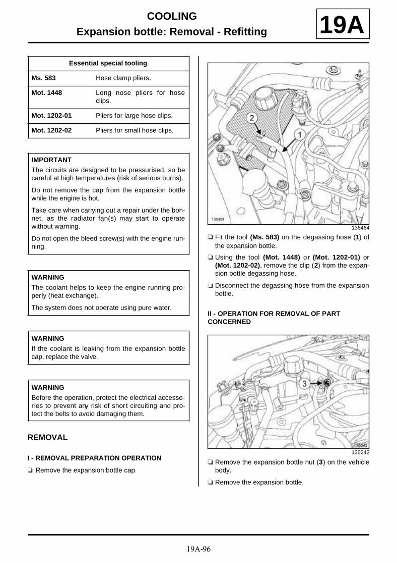
19A-96
COOLINGExpansion bottle: Removal - Refitting 19A
REMOVAL
I - REMOVAL PREPARATION OPERATION
a Remove the expansion bottle cap.
a Fit the tool (Ms. 583) on the degassing hose (1) ofthe expansion bottle.
a Using the tool (Mot. 1448) or (Mot. 1202-01) or(Mot. 1202-02), remove the clip (2) from the expan-sion bottle degassing hose.
a Disconnect the degassing hose from the expansionbottle.
II - OPERATION FOR REMOVAL OF PART CONCERNED
a Remove the expansion bottle nut (3) on the vehiclebody.
a Remove the expansion bottle.
Essential special tooling
Ms. 583 Hose clamp pliers.
Mot. 1448 Long nose pliers for hoseclips.
Mot. 1202-01 Pliers for large hose clips.
Mot. 1202-02 Pliers for small hose clips.
IMPORTANT
The circuits are designed to be pressurised, so becareful at high temperatures (risk of serious burns).
Do not remove the cap from the expansion bottlewhile the engine is hot.
Take care when carrying out a repair under the bon-net, as the radiator fan(s) may start to operatewithout warning.
Do not open the bleed screw(s) with the engine run-ning.
WARNING
The coolant helps to keep the engine running pro-perly (heat exchange).
The system does not operate using pure water.
WARNING
If the coolant is leaking from the expansion bottlecap, replace the valve.
WARNING
Before the operation, protect the electrical accesso-ries to prevent any risk of shor t circuiting and pro-tect the belts to avoid damaging them.
136464
135242

19A-97
COOLINGExpansion bottle: Removal - Refitting 19A
a Move aside the fuel vapour absorber bleed solenoidvalve (4) .
a Disconnect the fuel vapour absorber bleed solenoidvalve wiring from the expansion bottle.
a Unclip the manual priming pump from the expansionbottle at (5) .
a Remove the manual priming pump.
F4R or K4M
136464
F9Q or K9K
136606

19A-98
COOLINGExpansion bottle: Removal - Refitting 19A
a Fit the tool (Ms. 583) on the bottom hose of the ex-pansion bottle.
a Using the tool (Mot. 1448) or (Mot. 1202-01) or(Mot. 1202-02), remove the clip (6) from the expan-sion bottle bottom hose.
a Disconnect the bottom hose from the expansionbottle.
a Remove the expansion bottle.
REFITTING
I - REFITTING OPERATION FOR PART CONCERNED
a Position the expansion bottle.
a Connect the bottom hose to the expansion bottle.
a Using the tool (Mot. 1448) or (Mot. 1202-01) or(Mot. 1202-02), fit the clip for the expansion bottlebottom hose.
a Remove the tool (Ms. 583) from the bottom hose ofthe expansion bottle.
a Fit the manual priming pump.
a Clip the manual priming pump onto the expansionbottle.
a Fit the fuel vapour absorber bleed solenoid valve.
a Connect the wiring of the fuel vapour absorber bleedsolenoid valve to the expansion bottle.
II - FINAL OPERATION
a Refit the expansion bottle nut onto the vehicle body.
a Connect the degassing hose to the expansion bottle.
a Using the tool (Mot. 1448) or (Mot. 1202-01) or(Mot. 1202-02), fit the clip for the expansion bottledegassing hose.
a Remove the tool (Ms. 583) from the expansion bottledegassing hose.
a Top up the coolant level in the expansion bottle.
a Refit the expansion bottle cap.
135501
F9Q or K9K
F4R or K4M

19A-99
COOLINGElectric water pump: Removal - Refitting
F4R
19A
REMOVAL
REMOVAL PREPARATION OPERATION
a Position the vehicle on a two-post lift (see Vehicle:Towing and lifting) (02A, Lifting equipment).
a Disconnect the battery (see Battery: Removal - Re-fitting) (80A, Battery).
a Remove:
- the engine undertray bolts,
- the engine undertray.
a Remove the clips (1) from the electric coolant pump.
a Fit the tools (Ms. 583) on the hoses (2) .
a Separate the clips (3) on the electric coolant pumphoses using the tool (Mot. 1448).
a Disconnect the electric coolant pump hoses.
a Disconnect the connector (4) from the electric coo-lant pump.
a Remove the electric coolant pump.
Essential special tooling
Ms. 583 Hose clamp pliers.
Mot. 1448 Long nose pliers for hoseclips.
135754
135756
135757

19A-100
COOLINGElectric water pump: Removal - Refitting
F4R
19AREFITTING
I - REFITTING OPERATION FOR PART CONCERNED
a Refit the electric coolant pump.
a Connect
- the electric coolant pump connector,
- the electric coolant pump hoses.
a Position the clips on the electric coolant pump hosesusing the tool (Mot. 1448).
a Remove the tools (Ms. 583) from the cooling hoses.
II - FINAL OPERATION
a Refit:
- the electric coolant pump clips,
- the engine undertray.
a Connect the battery (see Battery: Removal - Refit-ting) (80A, Battery).
a Perform the following operations:
- top up the coolant level,
- bleed the cooling system (see 19A, Cooling, Coo-ling circuit: Draining - Refilling, page 19A-17) .

19A-101
COOLINGCoolant temperature sensor: Removal - Refitting
K4M
19A
REMOVAL
I - REMOVAL PREPARATION OPERATION
a Remove the front engine cover.
II - OPERATION FOR REMOVAL OF PART CONCERNED
a Disconnect the coolant temperature sensor connec-tor (1) .
a Remove:
- the clip (2) from the coolant temperature sensor,
- the coolant temperature sensor,
- the coolant temperature sensor seal.
REFITTING
I - REFITTING PREPARATION OPERATION
a parts always to be replaced: coolant temperatu-re sensor seal (10,06,01,18).
a Use SURFACE CLEANER (see Vehicle: Parts and ingredients for the repairwork) (04B, Consu-mables - Products) to clean and degrease:
- the seal housing in the water chamber,
- the seal mating face of the coolant temperaturesensor if reused.
II - REFITTING OPERATION FOR PART CONCERNED
a Refit:
- the coolant temperature sensor fitted with a newseal,
- the coolant temperature sensor clip.
a Connect the coolant temperature sensor connector.
IMPORTANT
The circuits are designed to be pressurised, so becareful at high temperatures (risk of serious burns).
Do not remove the cap from the expansion bottlewhile the engine is hot.
Take care when carrying out a repair under the bon-net, as the radiator fan(s) may start to operatewithout warning.
Do not open the bleed screw(s) with the engine run-ning.
WARNING
Before the operation, protect the electrical accesso-ries to prevent any risk of shor t circuiting and pro-tect the belts to avoid damaging them.
WARNING
The coolant helps to keep the engine running pro-perly (heat exchange).
The system does not operate using pure water.
136553

19A-102
COOLINGCoolant temperature sensor: Removal - Refitting
K4M
19AIII - FINAL OPERATION
a Perform the following operations:
- top up of the coolant level,
- bleed the cooling system (see 19A, Cooling, Coo-ling circuit: Draining - Refilling, page 19A-17) .
a Refit the engine cover.

19A-103
COOLINGCoolant temperature sensor: Removal - Refitting
K9K
19A
REMOVAL
I - OPERATION FOR REMOVAL OF PART CONCERNED
a Position the vehicle on a two-post lift (see Vehicle:Towing and lifting) (02A, Lifting equipment).
a Remove:
- the engine cover,
- the battery (see Battery : Removal - Refitting)(80A, Battery),
- the battery tray (see Battery tray: Removal - Re-fitting) (80A, Battery),
- the front wheels (see Wheel: Removal - Refitting)(35A, Wheels and tyres),
- the front section of the front wheel arch liners (seeFront wheel arch liner: Removal - Refitting)(55A, Exterior protection),
- the engine undertray bolts,
- the engine undertray,
- the front bumper (see Front bumper: Removal -Refitting) (55A, Exterior protection).
a Drain the cooling system (see 19A, Cooling, Coo-ling circuit: Draining - Refilling, page 19A-17) .
a Unclip the expansion bottle bottom cooling hose (1)from the coolant outlet unit.
II - OPERATION FOR REMOVAL OF PART CONCERNED
a Disconnect the coolant temperature sensor connec-tor (2) .
a Remove:
- the clip (3) from the coolant temperature sensor,
- the coolant temperature sensor,
- the coolant temperature sensor seal.
IMPORTANT
Wear leaktight gloves (Nitrile type) for this opera-tion.
135484
114213

19A-104
COOLINGCoolant temperature sensor: Removal - Refitting
K9K
19AREFITTING
I - REFITTING PREPARATION OPERATION
a parts always to be replaced: coolant temperatu-re sensor seal (10,06,01,18).
a Use SURFACE CLEANER (see Vehicle: Parts and ingredients for the repairwork) (04B, Consu-mables - Products) to clean and degrease:
- the mating face of the coolant temperature sensorif it is to be reused,
- the coolant outlet unit.
II - REFITTING OPERATION FOR PART CONCERNED
a Refit:
- a new coolant temperature sensor seal on the coo-lant temperature sensor,
- the coolant temperature sensor,
- the coolant temperature sensor clip.
a Connect the coolant temperature sensor connector.
III - FINAL OPERATION
a Clip the expansion bottle bottom cooling hose ontothe coolant outlet unit.
a Refit:
- the front bumper (see Front bumper: Removal -Refitting) (55A, Exterior protection),
- the engine undertray,
- the front section of the front wheel arch liners (seeFront wheel arch liner: Removal - Refitting)(55A, Exterior protection),
- the front wheels (see Wheel: Removal - Refitting)(35A, Wheels and tyres),
- the battery tray (see Battery tray: Removal - Re-fitting) (80A, Battery),
- the battery (see Battery : Removal - Refitting)(80A, Battery),
- the engine cover.
a Fill and bleed the cooling system (see 19A, Coo-ling, Cooling circuit: Draining - Refilling, page19A-17) .

19A-105
COOLINGCoolant temperature sensor: Removal - Refitting
F9Q
19A
REMOVAL
I - REMOVAL PREPARATION OPERATION
a Position the vehicle on a two-post lift (see Vehicle:Towing and lifting) (02A, Lifting equipment).
a Drain the cooling system (see 19A, Cooling, Coo-ling circuit: Draining - Refilling, page 19A-17) .
a Remove:
- the engine cover,
- the battery (see Battery : Removal - Refitting)(80A, Battery),
- the diesel injection computer (see 13B, Diesel in-jection, Diesel injection computer: Removal -Refitting, page 13B-17) ,
- the battery tray (see Battery tray: Removal - Re-fitting) (80A, Battery).
II - OPERATION FOR REMOVAL OF PART CONCERNED
a Disconnect the coolant temperature sensor connec-tor (1) .
a Remove:
- the clip (2) from the coolant temperature sensor,
- the coolant temperature sensor,
- the coolant temperature sensor seal.
IMPORTANT
The circuits are designed to be pressurised, so becareful at high temperatures (risk of serious burns).
Do not remove the cap from the expansion bottlewhile the engine is hot.
Take care when carrying out a repair under the bon-net, as the radiator fan(s) may start to operatewithout warning.
Do not open the bleed screw(s) with the engine run-ning.
WARNINGBefore the operation, protect the electrical accesso-ries to prevent any risk of shor t circuiting and pro-tect the belts to avoid damaging them.
WARNING
The coolant helps to keep the engine running pro-perly (heat exchange).
The system does not operate using pure water.
135987
135986

19A-106
COOLINGCoolant temperature sensor: Removal - Refitting
F9Q
19AREFITTING
I - REFITTING PREPARATION OPERATION
a Use SURFACE CLEANER (see Vehicle: Partsand ingredients for the repairwork) (04B, Consu-mables - Products) to clean and degrease the ma-ting face of the coolant temperature sensor on thecoolant outlet unit.
a parts always to be replaced: coolant temperatu-re sensor seal (10,06,01,18).
II - REFITTING OPERATION FOR PART CONCERNED
a Refit:
- a new seal on the coolant temperature sensor,
- the coolant temperature sensor,
- the coolant temperature sensor clip.
a Connect the coolant temperature sensor connector.
III - FINAL OPERATION
a Refit:
- the battery tray (see Battery tray: Removal - Re-fitting) (80A, Battery),
- the diesel injection computer (see 13B, Diesel in-jection, Diesel injection computer: Removal -Refitting, page 13B-17) ,
- the battery (see Battery : Removal - Refitting)(80A, Battery),
- the engine cover.
a Fill and bleed the cooling system (see 19A, Coo-ling, Cooling circuit: Draining - Refilling, page19A-17) .

19A-107
COOLINGCoolant temperature sensor: Removal - Refitting
F4R
19A
REMOVAL
I - REMOVAL PREPARATION OPERATION
a Position the vehicle on a two-post lift (see Vehicle:Towing and lifting) (02A, Lifting equipment).
a Remove the front engine cover.
II - OPERATION FOR REMOVAL OF PART CONCERNED
a Disconnect the coolant temperature sensor connec-tor.
a Remove the coolant temperature sensor (1) .
REFITTING
REFITTING OPERATION FOR PART CONCERNED
a
a Refit the coolant temperature sensor.
a Torque tighten the coolant temperature sensor(32 N.m).
a Connect the coolant temperature sensor connector.
a Perform the following operations:
- top up the coolant level,
- bleed the cooling system (see 19A, Cooling, Coo-ling circuit: Draining - Refilling, page 19A-17) .
a Refit the engine cover.
Tightening torquesm
coolant temperaturesensor
32 N.m
IMPORTANT
The circuits are designed to be pressurised, so becareful at high temperatures (risk of serious burns).
Do not remove the cap from the expansion bottlewhile the engine is hot.
Take care when carrying out a repair under the bon-net, as the radiator fan(s) may start to operatewithout warning.
Do not open the bleed screw(s) with the engine run-ning.
WARNINGBefore the operation, protect the electrical accesso-ries to prevent any risk of shor t circuiting and pro-tect the belts to avoid damaging them.
WARNING
The coolant helps to keep the engine running pro-perly (heat exchange).
The system does not operate using pure water.
120244
Note:
Apply 1 to 2 drops of FRENETANCHE (seeVehicle: Parts and ingredients for the repai-rwork) (04B, Consumables - Products).
19B-1
EXHAUSTExhaust: Parts and consumables for the repair work 19B

19B-2
EXHAUSTExhaust: Parts and consumables for the repair work 19B
K4M
138076

19B-3
EXHAUSTExhaust: Parts and consumables for the repair work 19B
(1) Catalytic converter
(2) Expansion chamber
(3) Silencer
(zc) Area to be cut

19B-4
EXHAUSTExhaust: Parts and consumables for the repair work 19B
K9K, and 830 or 832
138074

19B-5
EXHAUSTExhaust: Parts and consumables for the repair work 19B
(1) Connecting pipe
(2) Silencer
(zc) Area to be cut
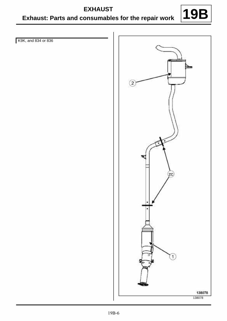
19B-6
EXHAUSTExhaust: Parts and consumables for the repair work 19B
K9K, and 834 or 836
138078

19B-7
EXHAUSTExhaust: Parts and consumables for the repair work 19B
(1) Particle filter
(2) Silencer
(zc) Area to be cut

19B-8
EXHAUSTExhaust: Parts and consumables for the repair work 19B
F9Q
138077

19B-9
EXHAUSTExhaust: Parts and consumables for the repair work 19B
(1) Particle filter
(2) Silencer
(zc) Area to be cut
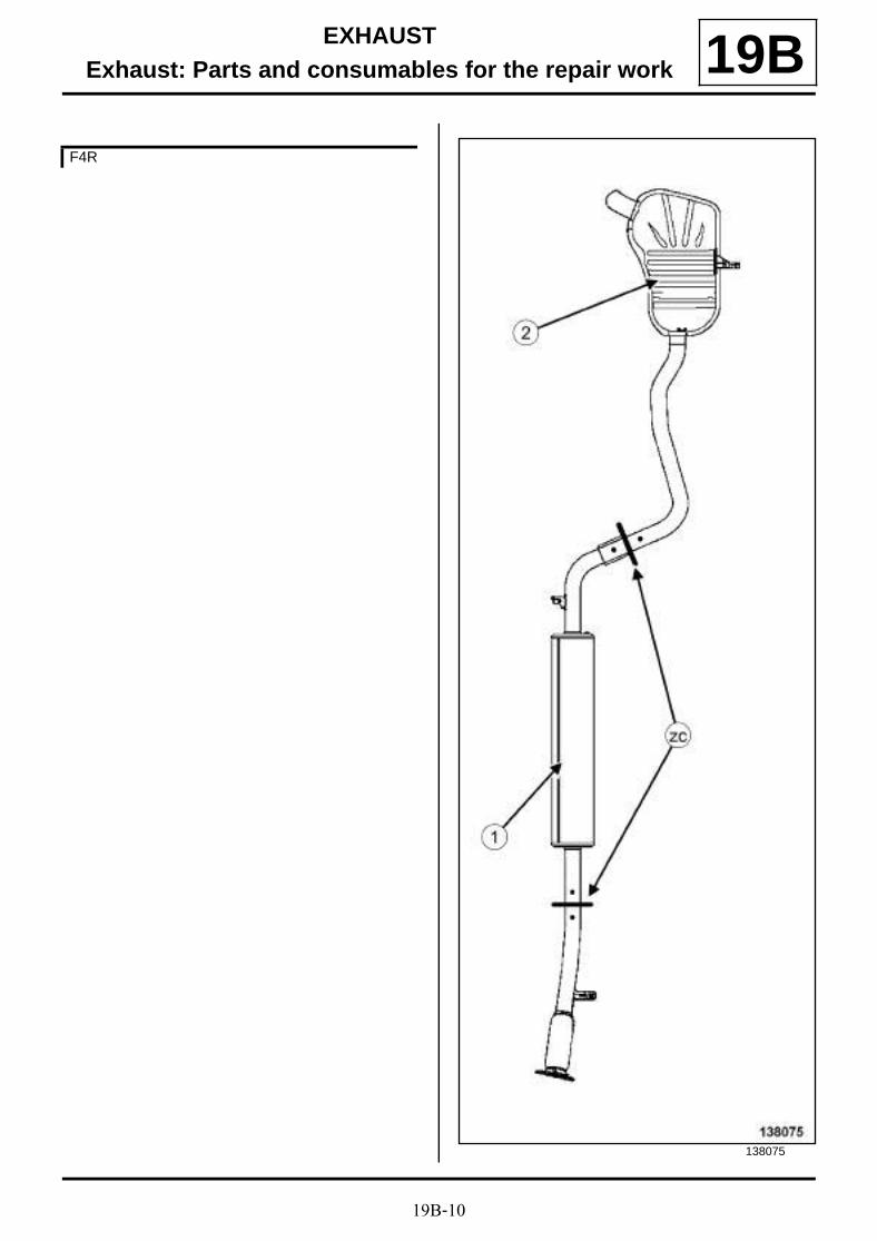
19B-10
EXHAUSTExhaust: Parts and consumables for the repair work 19B
F4R
138075
19B-11
EXHAUSTExhaust: Parts and consumables for the repair work 19B
(1) Connecting pipe
(2) Silencer
(zc) Area to be cut

19B-12
EXHAUSTExhaust: Precautions for repair 19B
The whole exhaust pipe is made of stainless steel.
The catalytic converter reaches high temperatures; donot park the vehicle close to flammable materials.
SPECIAL NOTES ON THE EXHAUST PIPE
1 - Cutting the exhaust pipe
The exhaust pipe is a single unit type.
To replace one of the components, the exhaust pipemust be cut.
It is essential:
- to correctly identify the area to be cut,
- to use the cutting tool (Mot. 1199-01),
- to position the After-Sales sleeve correctly.
2 - Identifying the area to be cut
Two marks on the exhaust pipe indicate the area to becut (see 19B, Exhaust, Exhaust: Parts and consu-mables for the repair work, page 19B-1) .
a - Front area to be cut
Essential special tooling
Mot. 1199-01 35/50 mm diameter and 50/95 mm diameter exhaust pipecutting tool. Complete assem-bly in kit.
WARNING
To prevent the surrounding components from ove-rheating, do not damage (tear, pierce, bend, etc.) aheat shield.
Any damaged heat shields must be replaced.
Note:
The sealing between the exhaust manifold surfaceand the catalytic converter must be perfect.
All seals removed must be replaced.
The catalytic converter must not be subjected tomechanical impacts during removal or refitting, asthis could damage it.
IMPORTANT
Catalytic converters contain ceramic fibres, theseare contained within a closed unit, and cannot dis-perse. Drilling or cutting catalytic converters is pro-hibited.
K4M
138160
K9K, and 830 or 832
138162

19B-13
EXHAUSTExhaust: Precautions for repair 19B
b - Rear area to be cut
K9K, and 834 or 836
138164
F9Q
138166
F4R
138168
K4M
138161
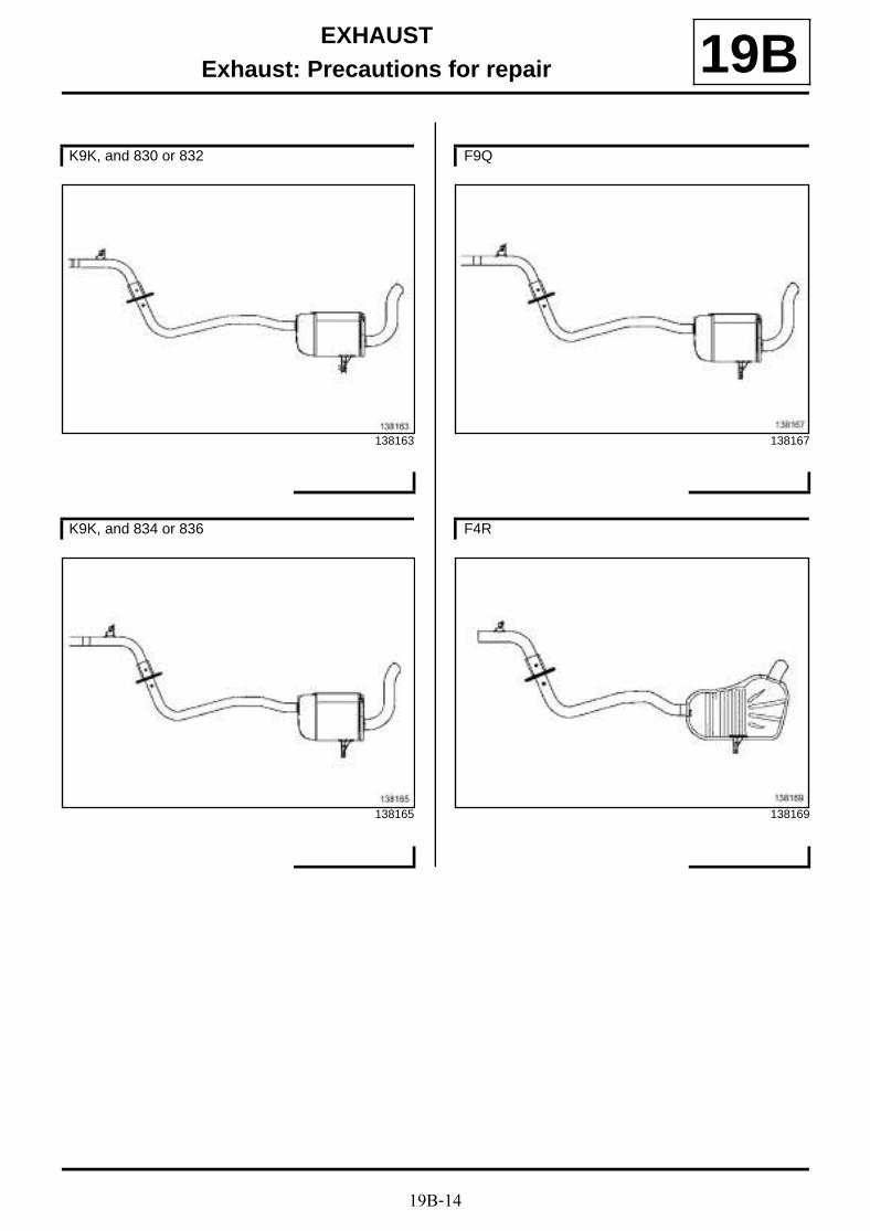
19B-14
EXHAUSTExhaust: Precautions for repair 19B
K9K, and 830 or 832
138163
K9K, and 834 or 836
138165
F9Q
138167
F4R
138169

19B-15
EXHAUSTExhaust: Precautions for repair 19B
Before cutting the pipe, draw a line (D) between themarks (P1) and (P2) .
The distance (X) between the two marks is 80 mm.
3 - Using tool Mot. 119-01
Position the tool on the pipe.
Tighten the two bolts on the cutting tool so that it gripsthe exhaust pipe.
Turn the cutting tool with the handle while gripping thepipe.
As the cut is made, continue to tighten the two bolts ofthe tool (do not overtighten the tool against the pipe, toprevent deformation during the cutting operation).
4 - Positioning of the spare part
5 - Fitting the After-Sales sleeve
Exhaust sleeve with one bolt
100649
133987
138173
WARNING
When replacing the intermediate section of theexhaust pipe (pipe on diesel versions, expansionchamber on petrol versions), shorten the spare partby 60 mm.
95478
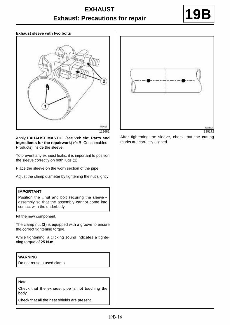
19B-16
EXHAUSTExhaust: Precautions for repair 19B
Exhaust sleeve with two bolts
Apply EXHAUST MASTIC (see Vehicle: Parts andingredients for the repairwork) (04B, Consumables -Products) inside the sleeve.
To prevent any exhaust leaks, it is important to positionthe sleeve correctly on both lugs (1) .
Place the sleeve on the worn section of the pipe.
Adjust the clamp diameter by tightening the nut slightly.
Fit the new component.
The clamp nut (2) is equipped with a groove to ensurethe correct tightening torque.
While tightening, a clicking sound indicates a tighte-ning torque of 25 N.m.
After tightening the sleeve, check that the cuttingmarks are correctly aligned.
119681
IMPORTANT
Position the « nut and bolt securing the sleeve »assembly so that the assembly cannot come intocontact with the underbody.
WARNING
Do not reuse a used clamp.
Note:
Check that the exhaust pipe is not touching thebody.
Check that all the heat shields are present.
138172
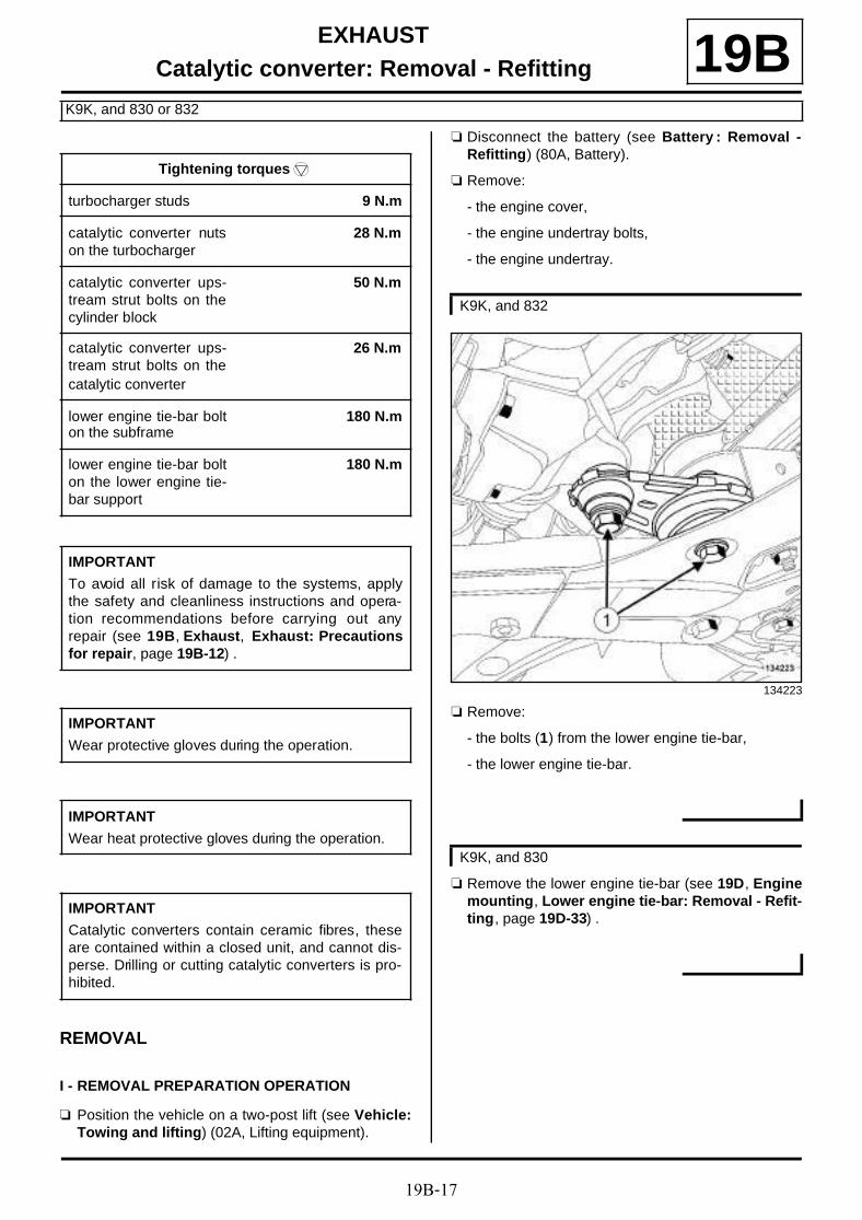
19B-17
EXHAUSTCatalytic converter: Removal - Refitting
K9K, and 830 or 832
19B
REMOVAL
I - REMOVAL PREPARATION OPERATION
a Position the vehicle on a two-post lift (see Vehicle:Towing and lifting) (02A, Lifting equipment).
a Disconnect the battery (see Battery : Removal -Refitting) (80A, Battery).
a Remove:
- the engine cover,
- the engine undertray bolts,
- the engine undertray.
a Remove:
- the bolts (1) from the lower engine tie-bar,
- the lower engine tie-bar.
a Remove the lower engine tie-bar (see 19D, Enginemounting, Lower engine tie-bar: Removal - Refit-ting, page 19D-33) .
Tightening torquesm
turbocharger studs 9 N.m
catalytic converter nutson the turbocharger
28 N.m
catalytic converter ups-tream strut bolts on thecylinder block
50 N.m
catalytic converter ups-tream strut bolts on thecatalytic converter
26 N.m
lower engine tie-bar bolton the subframe
180 N.m
lower engine tie-bar bolton the lower engine tie-bar support
180 N.m
IMPORTANT
To avoid all risk of damage to the systems, applythe safety and cleanliness instructions and opera-tion recommendations before carrying out anyrepair (see 19B, Exhaust, Exhaust: Precautionsfor repair, page 19B-12) .
IMPORTANT
Wear protective gloves during the operation.
IMPORTANT
Wear heat protective gloves during the operation.
IMPORTANT
Catalytic converters contain ceramic fibres, theseare contained within a closed unit, and cannot dis-perse. Drilling or cutting catalytic converters is pro-hibited.
K9K, and 832
134223
K9K, and 830

19B-18
EXHAUSTCatalytic converter: Removal - Refitting
K9K, and 830 or 832
19BII - REMOVAL STAGE FOR THE PART CONCERNED.
a Remove the bolts from the exhaust flange (2) fittedwith their springs.
a Move the exhaust pipe to one side.
a Remove the catalytic converter downstream strutbolt (3) from the catalytic converter.
a Undo:
- the catalytic converter downstream strut bolt (4) onthe gearbox,
- the catalytic converter downstream strut nut (5) onthe gearbox,
a Remove the catalytic converter downstream strut bysliding it upwards.
136392
134216

19B-19
EXHAUSTCatalytic converter: Removal - Refitting
K9K, and 830 or 832
19B
a Undo the catalytic converter upstream strut bolt (6) .
a Remove:
- the catalytic converter upstream strut bolts (7) ,
- the catalytic converter upstream strut,
- the catalytic converter nuts (8) ,
- the catalytic converter,
- the ring of the catalytic converter exhaust flange,
- the seal between the catalytic converter and theturbocharger.
REFITTING
I - REFITTING PREPARATION OPERATION
a Always replace the ring of the catalytic converter ex-haust flange.
a parts always to be replaced: seal between turbo-charger and catalytic converter (10,09,01,08)
a Use ABRASIVE PADS to clean the joint face:
- the intermediate pipe,
- on the catalytic converter in case of reuse,
- the turbocharger,
a Use SURFACE CLEANER (see Vehicle: Parts and ingredients for the repairwork) (04B, Consu-mables - Products) and CLEAN CLOTHS to de-grease the joint face:
- the intermediate pipe,
- on the catalytic converter in case of reuse,
- the turbocharger,
a If replacing the turbocharger studs, torque tightenthe turbocharger studs (9 N.m).
135486
109399
WARNING
To ensure proper sealing, the gasket surfacesmust be clean, dry and not greasy (avoid any fin-ger marks).

19B-20
EXHAUSTCatalytic converter: Removal - Refitting
K9K, and 830 or 832
19BII - REFITTING OPERATION FOR PART CONCERNED
a Refit:
- a new seal between the catalytic converter and theturbocharger on the turbocharger,
- the catalytic converter,
- the catalytic converter upstream strut.
a Fit without tightening:
- the catalytic converter upstream strut bolt on thecylinder block,
- the upstream strut bolt on the sump.
a Refit the catalytic converter downstream strut.
a Fit without tightening:
- the catalytic converter downstream strut bolt on thegearbox,
- the catalytic converter downstream strut nut on thegearbox,
- the catalytic converter upstream strut bolts on thecatalytic converter,
- the catalytic converter downstream strut bolt on thecatalytic converter,
- the catalytic converter nuts on the turbocharger.
a Tighten to torque:
- the catalytic converter nuts on the turbocharger(28 N.m),
- the catalytic converter upstream strut bolts onthe cylinder block (50 N.m).
a Tighten:
- the catalytic converter downstream strut bolt on themanual gearbox,
- the catalytic converter downstream strut nut on themanual gearbox.
a Torque tighten the catalytic converter upstreamstrut bolts on the catalytic converter (26 N.m).
a Tighten:
- the catalytic converter downstream strut bolt on thecatalytic converter,
- the catalytic converter upstream strut bolt on thesump.
a Refit a new ring on the catalytic converter exhaustflange.
a Fit the exhaust pipe on the catalytic converter.
a Refit the exhaust bracket bolts fitted with theirsprings.
III - FINAL OPERATION
a Refit the lower engine tie-bar.
a Tighten to torque:
- the lower engine tie-bar bolt on the subframe(180 N.m),
- the lower engine tie-bar bolt on the lower engi-ne tie-bar support (180 N.m).
a Refit the lower engine tie-bar (see 19D, Enginemounting, Lower engine tie-bar: Removal - Refit-ting, page 19D-33) .
a Refit:
- the engine undertray,
- the engine cover.
a Connect the battery (see Battery : Removal - Refit-ting) (80A, Battery).
Note:
Check that there is no contact between the cata-lytic conver ter and the turbocharger oil returnpipe during the entire catalytic converter tighte-ning operation.
K9K, and 832
K9K, and 830

19B-21
EXHAUSTCatalytic converter: Removal - Refitting
K4M
19B
REMOVAL
I - REMOVAL PREPARATION OPERATION
a Position the vehicle on a two-post lift (see Vehicle:Towing and lifting) (02A, Lifting equipment).
a Disconnect the battery (see Battery: Removal - Re-fitting) (80A, Battery).
a Remove:
- the downstream oxygen sensor (see 17B, Petrolinjection, Oxygen sensors: Removal - Refitting,page 17B-1) ,
- the engine undertray bolts,
- the engine undertray.
II - OPERATION FOR REMOVAL OF PART CONCERNED
a Cut the exhaust pipe (see 19B, Exhaust, Exhaust:Precautions for repair, page 19B-12) in the desi-gnated area to be cut (see 19B, Exhaust, Exhaust:Parts and consumables for the repair work, page19B-1) .
a Remove:
- the bolts (1) from the exhaust bracket,
- the catalytic converter,
- the exhaust bracket ring.
REFITTING
I - REFITTING PREPARATION OPERATION
a Clean the bearing faces of the catalytic converterusing ABRASIVE PADS (see Vehicle: Parts andingredients for the repairwork) (04B, Consuma-bles - Products).
Essential equipment
component jack
IMPORTANT
To avoid all risk of damage to the systems, applythe safety and cleanliness instructions and opera-tion recommendations before carrying out anyrepair (see 19B, Exhaust, Exhaust: Precautionsfor repair, page 19B-12) .
IMPORTANT
Wear heat protective gloves during the operation.
IMPORTANT
Catalytic converters contain ceramic fibres, theseare contained within a closed unit, and cannot dis-perse. Drilling or cutting catalytic converters is pro-hibited.
WARNING
To prevent the surrounding components from ove-rheating, do not damage (tear, pierce, bend, etc.) aheat shield.
Any damaged heat shields must be replaced.
Note:
Put a component jack under the catalytic con-verter.
135949
IMPORTANT
Catalytic converters contain ceramic fibres, theseare contained within a closed unit, and cannotdisperse. Drilling or cutting catalytic converters isprohibited.
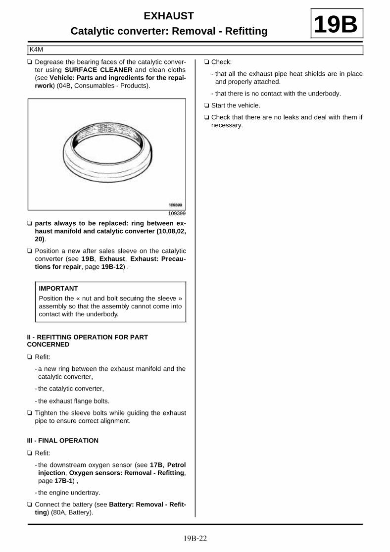
19B-22
EXHAUSTCatalytic converter: Removal - Refitting
K4M
19Ba Degrease the bearing faces of the catalytic conver-
ter using SURFACE CLEANER and clean cloths(see Vehicle: Parts and ingredients for the repai-rwork) (04B, Consumables - Products).
a parts always to be replaced: ring between ex-haust manifold and catalytic converter (10,08,02,20).
a Position a new after sales sleeve on the catalyticconverter (see 19B, Exhaust, Exhaust: Precau-tions for repair, page 19B-12) .
II - REFITTING OPERATION FOR PART CONCERNED
a Refit:
- a new ring between the exhaust manifold and thecatalytic converter,
- the catalytic converter,
- the exhaust flange bolts.
a Tighten the sleeve bolts while guiding the exhaustpipe to ensure correct alignment.
III - FINAL OPERATION
a Refit:
- the downstream oxygen sensor (see 17B, Petrolinjection, Oxygen sensors: Removal - Refitting,page 17B-1) ,
- the engine undertray.
a Connect the battery (see Battery: Removal - Refit-ting) (80A, Battery).
a Check:
- that all the exhaust pipe heat shields are in placeand properly attached.
- that there is no contact with the underbody.
a Start the vehicle.
a Check that there are no leaks and deal with them ifnecessary.
109399
IMPORTANT
Position the « nut and bolt securing the sleeve »assembly so that the assembly cannot come intocontact with the underbody.

19B-23
EXHAUSTCatalytic converter: Removal - Refitting
F9Q, and 870
19Ba The catalytic converter is not sold separately in the
Parts Department. To replace it, the particle filtermust be replaced (see 19B, Exhaust, Particle fil-ter: Removal - Refitting, page 19B-47) .

19B-24
EXHAUSTCatalytic converter: Removal - Refitting
F9Q, and 872
19B
REMOVAL
I - REMOVAL PREPARATION OPERATION
a Position the vehicle on a two-post lift (see Vehicle:Towing and lifting) (02A, Lifting equipment).
a Remove:
- the engine undertray bolts,
- the engine undertray.
II - OPERATION FOR REMOVAL OF PART CONCERNED
a Cut the exhaust pipe (see 19B, Exhaust, Exhaust:Precautions for repair, page 19B-12) in the desi-gnated area to be cut (see 19B, Exhaust, Exhaust:Parts and consumables for the repair work, page19B-1) .
a Remove the bolts (1) from the catalytic converter.
a Remove:
- the nuts (2) from the exhaust flange,
- the catalytic converter,
- the exhaust flange seal.
REFITTING
I - REFITTING PREPARATION OPERATION
a Always replace the exhaust bracket seal.
IMPORTANT
To avoid all risk of damage to the systems, applythe safety and cleanliness instructions and opera-tion recommendations before carrying out anyrepair (see 19B, Exhaust, Exhaust: Precautionsfor repair, page 19B-12) .
WARNING
To prevent the surrounding components from ove-rheating, do not damage (tear, pierce, bend, etc.) aheat shield.
Any damaged heat shields must be replaced.
IMPORTANT
Wear heat protective gloves during the operation. 135633
135632

19B-25
EXHAUSTCatalytic converter: Removal - Refitting
F9Q, and 872
19BII - REFITTING OPERATION FOR PART CONCERNED
a Refit:
- a new exhaust flange seal,
- the catalytic converter.
a Fit a new After-Sales sleeve (see 19B, Exhaust, Ex-haust: Precautions for repair, page 19B-12) .
III - FINAL OPERATION
a Check:
- that there is no contact with the underbody,
- that all the exhaust pipe heat shields are in place.
a Start the vehicle.
a Check that there are no leaks.
a Refit the engine undertray.
IMPORTANT
Position the « nut and bolt securing the sleeve »assembly so that the assembly cannot come intocontact with the underbody.

19B-26
EXHAUSTCatalytic converter: Removal - Refitting
F4R
19B
REMOVAL
I - REMOVAL PREPARATION OPERATION
a Position the vehicle on a two-post lift (see Vehicle:Towing and lifting) (02A, Lifting equipment).
a Disconnect the battery (see Battery : Removal -Refitting) (80A, Battery).
a Remove:
- the engine cover,
- the engine undertray bolts,
- the engine undertray,
- the windscreen wiper arms (see Windscreen wi-per arm: Removal - Refitting) (85A, Wiping -Washing),
- the scuttle panel grille (see Scuttle panel grille:Removal - Refitting) (56A, Exterior equipment),
- the scoop under the scuttle panel grille (see Scoopunder scuttle panel grille: Removal - Refitting)(56A, Exterior equipment).
a Remove:
- the bolts (1) from the turbocharger heat shield,
- the turbocharger heat shield,
- the upstream oxygen sensor (see 17B, Petrol in-jection, Oxygen sensors: Removal - Refitting,page 17B-1) .
Tightening torquesm
catalytic converter studson the turbocharger
9 N.m
catalytic converter ups-tream strut bolts on thecatalytic converter
11 Nm
ca ta ly t i c converterupper bracket bolt onthe catalytic converter
11 N.m
catalytic converter nuts 40 N.m
catalytic converter strutbolt
8 N.m
catalytic converter strutnut
44 N.m
driveshaft relay bearingbolts
44 N.m
engine tie-bar supportbolts
62 N.m
IMPORTANT
Catalytic converters contain ceramic fibres, theseare contained within a closed unit, and cannot dis-perse. Drilling or cutting catalytic converters is pro-hibited.
IMPORTANT
Wear protective gloves during the operation.
134649

19B-27
EXHAUSTCatalytic converter: Removal - Refitting
F4R
19B
a Remove:
- the timing end lifting eye bolt (2) ,
- the lifting eye on the timing end,
- the front right-hand wheel (see Wheel: Removal -Refitting) (35A, Wheels and tyres),
- the front section of the front right-hand wheel archliner (see Front wheel arch liner: Removal - Re-fitting) (55A, Exterior protection).
a Drain the manual gearbox (see Manual gearboxoil: Draining - Refilling) (21A, Manual gearbox).
a Remove:
- the front right-hand wheel driveshaft (see Front ri-ght-hand wheel driveshaft: Removal - Refitting)(29A, Driveshafts),
- the right-hand differential output seal (see Diffe-rential output seal: Removal - Refitting) (21A,Manual gearbox),
- the lower engine tie-bar (see 19D, Engine moun-ting, Lower engine tie-bar: Removal - Refitting,page 19D-33) ,
- the connecting hose (see 19B, Exhaust, Connec-ting hose: Removal - Refitting, page 19B-60) .
a Remove the clips (3) from the electric coolant pump.
a Move aside the electric water pump.
a Remove:
- the lower engine tie-bar mounting bolts (4) ,
- the lower engine tie-bar support.
137955 135754
136504

19B-28
EXHAUSTCatalytic converter: Removal - Refitting
F4R
19B
a Remove:
- the bolts (5) from the driveshaft relay bearing,
- the driveshaft relay bearing.
a Remove
- the bolt (6) from the catalytic converter strut,
- the catalytic converter strut nut (7) ,
- the catalytic converter strut.
a Disconnect the downstream oxygen sensor connec-tor (8) .
a Unclip the downstream oxygen sensor wiring.
II - OPERATION FOR REMOVAL OF PART CONCERNED
If replacing the catalytic converter
a Remove the downstream oxygen sensor (see 17B,Petrol injection, Oxygen sensors: Removal - Re-fitting, page 17B-1) .
135708
111627
21926

19B-29
EXHAUSTCatalytic converter: Removal - Refitting
F4R
19B
a Remove:
- the bolt (9) from the catalytic converter upper brac-ket on the catalytic converter,
- the bolt (10) from the upstream strut of the catalyticconverter on the catalytic converter,
- the catalytic converter nuts (11) ,
- the catalytic converter,
- the seal between the catalytic converter and theturbocharger.
REFITTING
I - REFITTING PREPARATION OPERATION
a parts always to be replaced: seal between turbo-charger and catalytic converter (10,09,01,08).
a parts always to be replaced: catalytic converterstud on the turbocharger (if loosened) (10,09,01,04).
If replacing the catalytic converter
a Remove the downstream oxygen sensor (see 17B,Petrol injection, Oxygen sensors: Removal - Re-fitting, page 17B-1) .
II - REFITTING OPERATION FOR PART CONCERNED
a Refit:
- a new seal between the turbocharger and the cata-lytic converter,
- the catalytic converter.
a Fit without tightening:
- the catalytic converter upper bracket bolt on the ca-talytic converter,
- the catalytic converter nuts,
- the catalytic converter upstream strut bolt on thecatalytic converter.
a Tighten to torque:
- the catalytic converter upstream strut bolts onthe catalytic converter (11 Nm),
- the catalytic converter upper bracket bolt onthe catalytic converter (11 N.m),
- the catalytic converter nuts (40 N.m).
III - FINAL OPERATION
a Clip on the downstream oxygen sensor wiring.
a Connect the downstream oxygen sensor connector.
21926
Note:
If a stud loosens during removal, coat it withHIGH RESISTANCE THREADLOCK (see Vehi-cle: Parts and ingredients for the repairwork)(04B, Consumables - Products).
Torque tighten the catalytic converter studs onthe turbocharger (9 N.m).
WARNING
To prevent the surrounding components fromoverheating, do not damage (tear, pierce, bend,etc.) a heat shield.
Any damaged heat shields must be replaced.

19B-30
EXHAUSTCatalytic converter: Removal - Refitting
F4R
19Ba Refit:
- the connecting hose (see 19B, Exhaust, Connec-ting hose: Removal - Refitting, page 19B-60) ,
- the catalytic converter strut.
a Fit without tightening:
- the catalytic converter strut nut,
- the catalytic converter strut bolt.
a Tighten to torque:
- the catalytic converter strut bolt (8 N.m),
- the catalytic converter strut nut (44 N.m).
a Refit the driveshaft relay bearing.
a Fit the driveshaft relay bearing bolt (3) without tighte-ning it.
a Torque tighten in order the driveshaft relay bea-ring bolts (44 N.m).
a Refit:
- the lower engine tie-bar support,
- the engine tie-bar support bolts.
a Torque tighten the engine tie-bar support bolts(62 N.m).
a Fit the electric coolant pump.
a Refit:
- the electric coolant pump clips,
- the lower engine tie-bar (see 19D, Engine moun-ting, Lower engine tie-bar: Removal - Refitting,page 19D-33) ,
- a new right-hand differential output seal (see Diffe-rential output seal: Removal - Refitting) (21A,Manual gearbox),
- the front right-hand wheel driveshaft (see Front ri-ght-hand wheel driveshaft: Removal - Refitting)(29A, Driveshafts).
a Fill the manual gearbox (see Manual gearbox oil:Draining - Refilling) (21A, Manual gearbox).
a Refit:
- the front section of the front right-hand wheel archliner (see Front wheel arch liner: Removal - Re-fitting) (55A, Exterior protection),
- the front right-hand wheel (see Wheel: Removal -Refitting) (35A, Wheels and tyres),
- the lifting eye on the timing end,
- the upstream oxygen sensor (see 17B, Petrol in-jection, Oxygen sensors: Removal - Refitting,page 17B-1) ,
- the turbocharger heat shield,
- the scoop under the scuttle panel grille (see Scoopunder scuttle panel grille: Removal - Refitting)(56A, Exterior equipment),
- the scuttle panel grille (see Scuttle panel grille:Removal - Refitting) (56A, Exterior equipment),
- the windscreen wiper arms (see Windscreen wi-per arm: Removal - Refitting) (85A, Wiping -Washing),
- the engine undertray,
- the engine cover.
a Connect the battery (see Battery : Removal - Refit-ting) (80A, Battery).135708

19B-31
EXHAUSTExpansion chamber: Removal - Refitting
F4R
19B
REMOVAL
I - REMOVAL PREPARATION OPERATION
a Position the vehicle on a two-post lift (see Vehicle:Towing and lifting) (02A, Lifting equipment).
a Place a component jack under the expansionchamber.
II - OPERATION FOR REMOVAL OF PART CONCERNED
a Remove:
- the expansion chamber bolt (1) ,
- the exhaust silencer bolt (2) .
a Cut the exhaust pipe (see 19B, Exhaust, Exhaust:Precautions for repair, page 19B-12) in the desi-gnated area to be cut (see 19B, Exhaust, Exhaust:Parts and consumables for the repair work, page19B-1) .
a Remove the expansion chamber.
Essential equipment
component jack
IMPORTANT
To avoid all risk of damage to the systems, applythe safety and cleanliness instructions and opera-tion recommendations before carrying out anyrepair (see 19B, Exhaust, Exhaust: Precautionsfor repair, page 19B-12)
WARNING
To prevent the surrounding components from ove-rheating, do not damage (tear, pierce, bend, etc.) aheat shield.
Any damaged heat shields must be replaced.
IMPORTANT
Wear heat protective gloves during the operation.
136958
136957

19B-32
EXHAUSTExpansion chamber: Removal - Refitting
F4R
19BREFITTING
I - OPERATION FOR REFITTING PART CONCERNED
a Refit the expansion chamber using a componentjack.
a Fit new after-sales sleeves (see 19B, Exhaust, Ex-haust: Precautions for repair, page 19B-12) .
a Refit:
- the expansion chamber bolt,
- the exhaust silencer bolt.
II - FINAL OPERATION
a Check:
- that all the exhaust pipe heat shields are in placeand properly attached.
- that there is no contact with the underbody,
- that there are no leaks.
IMPORTANT
Position the « nut and bolt securing the sleeve »assembly so that the assembly cannot come intocontact with the underbody.

19B-33
EXHAUSTExpansion chamber: Removal - Refitting
K4M
19B
REMOVAL
I - REMOVAL PREPARATION OPERATION
a Position the vehicle on a two-post lift (see Vehicle:Towing and lifting) (02A, Lifting equipment).
II - OPERATION FOR REMOVAL OF PART CONCERNED
a Cut the exhaust system (see 19B, Exhaust, Ex-haust: Precautions for repair, page 19B-12) in thecutting zone provided for this purpose on either sideof the expansion chamber (see 19B, Exhaust, Ex-haust: Parts and consumables for the repairwork, page 19B-1) .
a Remove the bolts (1) of the rubber mounting bushon the expansion chamber.
a Remove:
- the earth on the rubber mounting bush (2) ,
- the expansion chamber.
III - REFITTING OPERATION FOR PART CONCERNED
a Refit:
- the expansion chamber,
- the earth on the rubber mounting bush,
- the bolts of the rubber mounting bush on the ex-pansion chamber.
a Fit new after-sales sleeves (see 19B, Exhaust, Ex-haust: Precautions for repair, page 19B-12) .
a Tighten the sleeves while supporting the exhaustpipe to ensure they are aligned.
Essential equipment
component jack
IMPORTANT
To avoid all risk of damage to the systems, applythe safety and cleanliness instructions and opera-tion recommendations before carrying out anyrepair (see 19B, Exhaust, Exhaust: Precautionsfor repair, page 19B-12) .
WARNING
To prevent the surrounding components from ove-rheating, do not damage (tear, pierce, bend, etc.) aheat shield.
Any damaged heat shields must be replaced.
IMPORTANT
Wear heat protective gloves during the operation.
Note:
Place a component jack under the expansionchamber.
136449
Note:
If the rubber mounting bushes are damaged,replace them.
IMPORTANT
Position the « nut and bolt securing the sleeve »assembly so that the assembly cannot come intocontact with the underbody.
19B-34
EXHAUSTExpansion chamber: Removal - Refitting
K4M
19BIV - FINAL OPERATION
a Check:
- that there is no contact with the underbody,
- all the exhaust pipe heat shields are in place andproperly attached.
a Start the vehicle.
a Check that there are no leaks and deal with them ifnecessary.

19B-35
EXHAUSTConnector pipe: Removal - Refitting
K9K, and 830 or 832
19B
REMOVING THE CONNECTING PIPE
I - PREPARATION OPERATION FOR REMOVAL OF THE CONNECTING PIPE
a Position the vehicle on a two-post lift (see Vehicle:Towing and lifting) (02A, Lifting equipment).
a Cut the exhaust system (see Vehicle: Precautionsfor repair) in the cutting zone provided for thispurpose on either side of the connecting pipe (see19B, Exhaust, Exhaust: Parts and consumablesfor the repair work, page 19B-1) .
II - CONNECTING PIPE REMOVAL OPERATION
a
a Remove:
- the connecting pipe bolts (1) ,
- the connecting pipe balance weight (2) ,
- the connecting pipe.
REFITTING THE CONNECTING PIPE
I - CONNECTING PIPE REFITTING OPERATION
a Refit the connecting pipe equipped with the connec-ting pipe balance weight.
II - FINAL OPERATION
a
a Fit new after-sales sleeves (see 19B, Exhaust, Ex-haust: Precautions for repair, page 19B-12) .
a Check:
- that there is no contact with the underbody,
IMPORTANT
To avoid all risk of damage to the systems, applythe safety and cleanliness instructions and opera-tion recommendations before carrying out anyrepair (see 19B, Exhaust, Exhaust: Precautionsfor repair, page 19B-12) .
WARNING
To prevent the surrounding components from ove-rheating, do not damage (tear, pierce, bend, etc.) aheat shield.
Any damaged heat shields must be replaced.
IMPORTANT
Wear heat protective gloves during the operation.135629
Note:
If the rubber mounting bush is damaged, it mustalways be replaced.
IMPORTANT
Position the « nut and bolt securing the sleeve »assembly so that the assembly cannot come intocontact with the underbody.

19B-36
EXHAUSTConnector pipe: Removal - Refitting
K9K, and 830 or 832
19B- the presence and correct positioning of all the ex-haust pipe heat shields.
a Start the vehicle.
a Check that there are no leaks and deal with them ifnecessary.
REMOVING THE EXHAUST DOWNPIPE
I - PREPARATION OPERATION FOR REMOVAL OF THE EXHAUST DOWNPIPE
a Position the vehicle on a two-post lift (see Vehicle:Towing and lifting) (02A, Lifting equipment).
a Cut the exhaust system (see Vehicle: Precautionsfor repair) in the cutting zone provided for thispurpose on either side of the connecting pipe (see19B, Exhaust, Exhaust: Parts and consumablesfor the repair work, page 19B-1) .
II - EXHAUST DOWNPIPE REMOVAL OPERATION
a Remove:
- the exhaust downpipe bolts (3) from the catalyticconverter,
- the sealing ring of the catalytic converter exhaustflange,
- the exhaust downpipe.
REFITTING THE EXHAUST DOWNPIPE
I - PREPARATION OPERATION FOR REFITTING THE EXHAUST DOWNPIPE
a Always replace the catalytic converter exhaust flan-ge sealing ring.
a Clean the bearing face of the exhaust downpipeusing SURFACE CLEANER (see Vehicle: Partsand ingredients for the repairwork) (04B, Consu-mables - Products).
II - EXHAUST DOWNPIPE REFITTING OPERATION
a Refit:
- the new sealing ring of the catalytic converter ex-haust flange,
- the exhaust downpipe.
a Fit the exhaust downpipe bolts onto the catalyticconverter, without tightening.
III - FINAL OPERATION
a
a Fit a new After-Sales sleeve (see 19B, Exhaust, Ex-haust: Precautions for repair, page 19B-12) .
a Tighten the exhaust downpipe bolts on the catalyticconverter.
a Check:
- that there is no contact with the underbody,
- the presence and correct positioning of all the ex-haust pipe heat shields.
136392
109399
IMPORTANT
Position the « nut and bolt securing the sleeve »assembly so that the assembly cannot come intocontact with the underbody.

19B-37
EXHAUSTConnector pipe: Removal - Refitting
K9K, and 830 or 832
19Ba Start the vehicle.
a Check that there are no leaks and deal with them ifnecessary.

19B-38
EXHAUSTConnector pipe: Removal - Refitting
F9Q
19B
REMOVAL
I - REMOVAL PREPARATION OPERATION
a Position the vehicle on a two-post lift (see Vehicle:Towing and lifting) (02A, Lifting equipment).
II - OPERATION FOR REMOVAL OF PART CONCERNED
a Cut the exhaust pipe (see 19B, Exhaust, Exhaust:Precautions for repair, page 19B-12) in the desi-gnated area to be cut (see 19B, Exhaust, Exhaust:Parts and consumables for the repair work, page19B-1) .
a
a Remove:
- the connecting pipe bolts (1) ,
- the balance weight of the connecting pipe,
- the connecting pipe.
REFITTING
I - REFITTING OPERATION FOR PART CONCERNED
a Refit the connecting pipe equipped with the connec-ting pipe balance weight.
a Fit new after-sales sleeves (see 19B, Exhaust, Ex-haust: Precautions for repair, page 19B-12) .
II - FINAL OPERATION
a Check:
- that there is no contact with the underbody,
IMPORTANT
To avoid all risk of damage to the systems, applythe safety and cleanliness instructions and opera-tion recommendations before carrying out anyrepair (see 19B, Exhaust, Exhaust: Precautionsfor repair, page 19B-12) .
WARNING
To prevent the surrounding components from ove-rheating, do not damage (tear, pierce, bend, etc.) aheat shield.
Any damaged heat shields must be replaced.
IMPORTANT
Wear heat protective gloves during the operation. 136212
Note:
If the rubber mounting bush is damaged, it mustalways be replaced.
IMPORTANT
Position the « nut and bolt securing the sleeve »assembly so that the assembly cannot come intocontact with the underbody.

19B-39
EXHAUSTConnector pipe: Removal - Refitting
F9Q
19B- that all exhaust pipe heat shields are present.
a Start the vehicle.
a Check that there are no leaks.

19B-40
EXHAUSTSilencer: Removal - Refitting
F4R
19B
REMOVAL
I - REMOVAL PREPARATION OPERATION
a Position the vehicle on a two-post lift (see Vehicle:Towing and lifting) (02A, Lifting equipment).
II - OPERATION FOR REMOVAL OF PART CONCERNED
a Remove the expansion chamber bolt (1) .
a Fit a component jack underneath the exhaust silen-cer.
a Remove the exhaust silencer bolt (2) .
a Cut the exhaust pipe (see 19B, Exhaust, Exhaust:Precautions for repair, page 19B-12) in the desi-gnated area to be cut (see 19B, Exhaust, Exhaust:Parts and consumables for the repair work, page19B-1) .
a Remove the exhaust silencer.
Essential equipment
component jack
IMPORTANT
To avoid all risk of damage to the systems, applythe safety and cleanliness instructions and opera-tion recommendations before carrying out anyrepair (see 19B, Exhaust, Exhaust: Precautionsfor repair, page 19B-12) .
IMPORTANTWear heat protective gloves during the operation.
WARNING
To prevent the surrounding components from ove-rheating, do not damage (tear, pierce, bend, etc.) aheat shield.
Any damaged heat shields must be replaced.
136958
136957
19B-41
EXHAUSTSilencer: Removal - Refitting
F4R
19BREFITTING
I - REFITTING OPERATION FOR PARTS CONCERNED
a Fit the exhaust silencer using a component jack.
a Refit:
- the exhaust silencer bolt,
- the expansion chamber bolt.
a Fit a new After-Sales sleeve between the expansionchamber and the exhaust silencer (see 19B, Ex-haust, Exhaust: Precautions for repair, page19B-12) .
a Tighten the sleeve while supporting the exhaust pipeto ensure they are aligned.
II - FINAL OPERATION
a Check:
- that all the exhaust pipe heat shields are in placeand properly attached.
- that there is no contact with the underbody,
- that there are no leaks.
IMPORTANT
Position the « nut and bolt securing the sleeve »assembly so that the assembly cannot come intocontact with the underbody.
IMPORTANT
Wear protective gloves during the operation.

19B-42
EXHAUSTSilencer: Removal - Refitting
K4M
19B
REMOVAL
I - REMOVAL PREPARATION OPERATION
a Position the vehicle on a two-post lift (see Vehicle:Towing and lifting) (02A, Lifting equipment).
II - OPERATION FOR REMOVAL OF PART CONCERNED
a Cut the exhaust pipe (see 19B, Exhaust, Exhaust:Precautions for repair, page 19B-12) in the desi-gnated area to be cut (see 19B, Exhaust, Exhaust:Parts and consumables for the repair work, page19B-1) .
a Remove the silencer rubber mounting bush bolts (1).
a Remove the silencer.
REFITTING
I - REFITTING OPERATION FOR PART CONCERNED
a Refit:
- the silencer,
- the rubber mounting bush bolts to the silencer.
a Fit a new After-Sales sleeve (see 19B, Exhaust, Ex-haust: Precautions for repair, page 19B-12) .
a Tighten the sleeve while supporting the exhaust pipeto ensure they are aligned.
Essential equipment
component jack
IMPORTANT
To avoid all risk of damage to the systems, applythe safety and cleanliness instructions and opera-tion recommendations before carrying out anyrepair (see 19B, Exhaust, Exhaust: Precautionsfor repair, page 19B-12) .
WARNINGTo prevent the surrounding components from ove-rheating, do not damage (tear, pierce, bend, etc.) aheat shield.
Any damaged heat shields must be replaced.
IMPORTANT
Wear heat protective gloves during the operation.
Note:
Place a component jack under the silencer.
135929
Note:
If the rubber mounting bushes are damaged,replace them.
IMPORTANT
Position the « nut and bolt securing the sleeve »assembly so that the assembly cannot come intocontact with the underbody.

19B-43
EXHAUSTSilencer: Removal - Refitting
K4M
19BII - FINAL OPERATION
a Check:
- that all the exhaust pipe heat shields are in placeand properly attached.
- that there is no contact with the underbody.
a Start the vehicle.
a Check that there are no leaks and deal with them ifnecessary.

19B-44
EXHAUSTSilencer: Removal - Refitting
K9K
19B
REMOVAL
I - REMOVAL PREPARATION OPERATION
a Position the vehicle on a two-post lift (see Vehicle:Towing and lifting) (02A, Lifting equipment).
a Position a component jack under the exhaust silen-cer.
II - OPERATION FOR REMOVAL OF PART CONCERNED
a Remove the silencer bolts (1) .
a Cut the exhaust pipe (see 19B, Exhaust, Exhaust:Precautions for repair, page 19B-12) in the desi-gnated area to be cut (see 19B, Exhaust, Exhaust:Parts and consumables for the repair work, page19B-1) .
a Remove the exhaust silencer.
REFITTING
I - REFITTING OPERATION FOR PART CONCERNED
a Refit the exhaust silencer using a component jack.
a Fit a new After-Sales sleeve (see 19B, Exhaust, Ex-haust: Precautions for repair, page 19B-12) .
II - FINAL OPERATION
a Check:
- that there is no contact with the underbody,
- that all the exhaust pipe heat shields are in place.
a Start the vehicle.
Essential equipment
component jack
IMPORTANT
To avoid all risk of damage to the systems, applythe safety and cleanliness instructions and opera-tion recommendations before carrying out anyrepair (see 19B, Exhaust, Exhaust: Precautionsfor repair, page 19B-12) .
WARNINGTo prevent the surrounding components from ove-rheating, do not damage (tear, pierce, bend, etc.) aheat shield.
Any damaged heat shields must be replaced.
IMPORTANT
Wear heat protective gloves during the operation.
135628
IMPORTANT
Position the « nut and bolt securing the sleeve »assembly so that the assembly cannot come intocontact with the underbody.

19B-45
EXHAUSTSilencer: Removal - Refitting
K9K
19Ba Check that there are no leaks.

19B-46
EXHAUSTSilencer: Removal - Refitting
F9Q
19B
REMOVAL
I - REMOVAL PREPARATION OPERATION
a Position the vehicle on a two-post lift (see Vehicle:Towing and lifting) (02A, Lifting equipment).
a Position a component jack under the exhaust silen-cer.
II - OPERATION FOR REMOVAL OF PART CONCERNED
a Cut the exhaust pipe (see 19B, Exhaust, Exhaust:Precautions for repair, page 19B-12) in the desi-gnated area to be cut (see 19B, Exhaust, Exhaust:Parts and consumables for the repair work, page19B-1) .
a Remove:
- the silencer bolts (1) ,
- the silencer.
REFITTING
I - REFITTING OPERATION FOR PART CONCERNED
a Refit the exhaust silencer using a component jack.
a Fit a new After-Sales sleeve (see 19B, Exhaust, Ex-haust: Precautions for repair, page 19B-12) .
II - FINAL OPERATION
a Remove the component jack.
a Check:
- that there is no contact with the underbody,
- that all the exhaust pipe heat shields are in place.
a Start the vehicle.
a Check that there are no leaks.
Essential equipment
component jack
IMPORTANT
To avoid all risk of damage to the systems, applythe safety and cleanliness instructions and opera-tion recommendations before carrying out anyrepair (see 19B, Exhaust, Exhaust: Precautionsfor repair, page 19B-12) .
WARNINGTo prevent the surrounding components from ove-rheating, do not damage (tear, pierce, bend, etc.) aheat shield.
Any damaged heat shields must be replaced.
IMPORTANT
Wear heat protective gloves during the operation.
136213
IMPORTANT
Position the « nut and bolt securing the sleeve »assembly so that the assembly cannot come intocontact with the underbody.

19B-47
EXHAUSTParticle filter: Removal - Refitting
F9Q, and 870
19B
REMOVAL
I - REMOVAL PREPARATION OPERATION
a Position the vehicle on a two-post lift (see Vehicle:Towing and lifting) (02A, Lifting equipment).
a Disconnect the battery (see Battery : Removal -Refitting) (80A, Battery).
a Remove:
- the engine undertray bolts,
- the engine undertray.
a Remove the take-off pipe from the particle filter tem-perature sensor (1) .
a Remove:
- the take-off pipe of the particle filter pressure sen-sor (2) ,
- the bolt (3) of the particle filter pressure sensor pi-pe.
II - OPERATION FOR REMOVAL OF PART CONCERNED
a Cut the exhaust pipe (see 19B, Exhaust, Exhaust:Precautions for repair, page 19B-12) in the desi-gnated area to be cut (see 19B, Exhaust, Exhaust:Parts and consumables for the repair work, page19B-1) .
Essential equipment
component jack
diagnostic tool
137208
137210

19B-48
EXHAUSTParticle filter: Removal - Refitting
F9Q, and 870
19B
a Remove the nuts (4) from the exhaust bracket.
a Place a component jack under the particle filter.
a Remove:
- the particle filter support bolts (5) ,
- particle filter.
- the exhaust flange seal.
REFITTING
I - REFITTING PREPARATION OPERATION
a Always replace the exhaust bracket seal.
a Use SURFACE CLEANER (see Vehicle: Partsand ingredients for the repairwork) (04B, Consu-mables - Products) to clean and degrease the bea-ring faces between the exhaust flange and theparticle filter.
II - REFITTING OPERATION FOR PART CONCERNED
a Refit:
- a new exhaust flange seal,
- the particle filter using the component jack,
- the particle filter support bolts,
- the exhaust flange bolts.
a Fit a new After-Sales sleeve and follow the instruc-tions (see 19B, Exhaust, Exhaust: Precautionsfor repair, page 19B-12) .
III - FINAL OPERATION
a Refit:
- the bolt of the particle filter pressure sensor pipe,
- the take-off pipe of the particle filter pressure sen-sor.
a Refit the take-off pipe of the particle filter temperatu-re sensor.
a Make sure that there is no contact with the underbo-dy.
a Connect the battery (see Battery : Removal - Refit-ting) (80A, Battery).
a Apply the after repair procedure using the diagnos-tic tool :
- connect the diagnostic tool,
- select « Injection computer » ,
- go to repair mode,
- display the « before/after repair procedure » for thecomputer selected,
- select « Particle filters » in the « List of compo-nents controlled by this computer » section,
- carry out the operations described in the « After re-pair procedure » section.
a Start the engine.
137211
137197
19B-49
EXHAUSTParticle filter: Removal - Refitting
F9Q, and 870
19Ba Check that there are no leaks and deal with them if
necessary.
a Refit the engine undertray.

19B-50
EXHAUSTExhaust gas temperature sensor: Removal - Refitting
F9Q, and 870
19B
REMOVAL
I - REMOVAL PREPARATION OPERATION
a Position the vehicle on a two-post lift (see Vehicle:Towing and lifting) (02A, Lifting equipment).
a Remove:
- the engine cover,
- the engine undertray bolts,
- the engine undertray,
- the windscreen wiper arms (see Rear screen wi-per arm: Removal - Refitting) (85A, Wiping -Washing),
- the scuttle panel grille (see Scuttle panel grille:Removal - Refitting) (56A, Exterior equipment),
- the scoop under the scuttle panel grille (see Scoopunder scuttle panel grille: Removal - Refitting)(56A, Exterior equipment),
- the battery (see Battery: Removal - Refitting)(80A, Battery),
- the battery tray (see Battery tray: Removal - Re-fitting) (80A, Battery),
- the intercooler air inlet pipe (see 12B, Turbochar-ging, Intercooler air inlet pipe: Removal - Refit-ting, page 12B-41) .
II - OPERATION FOR REMOVAL OF PART CONCERNED
a Disconnect the exhaust gas temperature sensorconnector (1) .
a Unclip the wiring (2) of the exhaust gas temperaturesensor.
Essential special tooling
Mot. 1807 Spanner for tighteningexhaust gas temperature sen-sor
Tightening torquesm
the exhaust gas tempe-rature sensor
40 N.m
137668
137669

19B-51
EXHAUSTExhaust gas temperature sensor: Removal - Refitting
F9Q, and 870
19B
a Remove the exhaust gas temperature sensor (3)using the tool (Mot. 1807).
REFITTING
I - REFITTING OPERATION FOR PART CONCERNED
a Refit the exhaust gas temperature sensor.
a Torque tighten the exhaust gas temperature sen-sor (40 N.m).
a Clip on the exhaust gas temperature sensor wiring.
a Connect the exhaust gas temperature sensor con-nector.
II - FINAL OPERATION
a Refit:
- the intercooler air inlet pipe (see 12B, Turbochar-ging, Intercooler air inlet pipe: Removal - Refit-ting, page 12B-41) ,
- the battery tray (see Battery tray: Removal - Re-fitting) (80A, Battery),
- the battery (see Battery: Removal - Refitting)(80A, Battery),
- the scoop under the scuttle panel grille (see Scoopunder scuttle panel grille: Removal - Refitting)(56A, Exterior equipment),
- the scuttle panel grille (see Scuttle panel grille:Removal - Refitting) (56A, Exterior equipment),
- the windscreen wiper arms (see Rear screen wi-per arm: Removal - Refitting) (85A, Wiping -Washing),
- the engine undertray,
- the engine cover.
137667

19B-52
EXHAUSTParticle filter pressure sensor: Removal - Refitting
F9Q, and 870
19B
REMOVAL
I - REMOVAL PREPARATION OPERATION
a Position the vehicle on a two-post lift (see Vehicle:Towing and lifting) (02A, Lifting equipment).
a Disconnect the battery (see Battery: Removal - Re-fitting) (80A, Battery).
a Refit:
- the engine undertray bolts,
- the engine undertray.
II - OPERATION FOR REMOVAL OF PART CONCERNED
a Disconnect the particle filter pressure sensor con-nector (1) .
a Remove the particle filter pressure sensor nut (2) .
a Remove:
- the bolt of the particle filter pressure measurementpipe (3) ,
- the particle filter pressure measurement pipe (4) ,
- the pressure sensor with its pipe.
REFITTING
I - REFITTING PREPARATION OPERATION
a Coat the threaded union of the particle filter pressuremeasurement pipe with COPPER-ALUMINIUM LU-BRICANT (see Vehicle: Parts and consumablesfor repair) (04B, Consumables - Products).
II - REFITTING OPERATION FOR PART CONCERNED
a Refit:
- the particle filter pressure measurement pipe,
- the bolt of the particle filter pressure measurementpipe,
- the particle filter pressure sensor nut.
a Connect the particle filter pressure sensor connec-tor.
III - FINAL OPERATION
a Refit the engine undertray.
a Connect the battery (see Battery : Removal - Refit-ting) (80A, Battery).
IMPORTANT
To avoid all risk of damage to the systems, applythe safety and cleanliness instructions and opera-tion recommendations before carrying out anyrepair (see 19B, Exhaust, Exhaust: Precautionsfor repair, page 19B-12) .
137198
137210

19B-53
EXHAUSTParticle filter temperature sensors: Removal - Refitting
F9Q, and 870
19BREMOVAL
I - REMOVAL PREPARATION OPERATION
a Position the vehicle on a two-post lift (see Vehicle:Towing and lifting) (02A, Lifting equipment).
a Disconnect the battery (see Battery : Removal -Refitting) (80A, Battery).
a Remove:
- the engine undertray bolts,
- the engine undertray.
II - OPERATION FOR REMOVAL OF PART CONCERNED
a Disconnect the particle filter temperature sensorconnector (1) .
a Unclip the particle filter temperature sensor wiring(2) .
a Remove the particle filter temperature sensor (3) .
REFITTING
I - REFITTING PREPARATION OPERATION
a Coat the threading of the particle filter temperaturesensor with COPPER-ALUMINIUM LUBRICANT(see Vehicle: Parts and ingredients for the repai-rwork) (04B, Consumables - Products).
II - REFITTING OPERATION FOR PART CONCERNED
a Refit the particle filter temperature sensor.
a Clip on the particle filter temperature sensor wiring.
a Connect the particle filter temperature sensor con-nector.
III - FINAL OPERATION
a Refit the engine undertray.
a Connect the battery (see Battery : Removal - Refit-ting) (80A, Battery).
138087
137208

19B-54
EXHAUSTExhaust fuel injector: Removal - Refitting
F9Q, and 870
19B
REMOVAL
I - REMOVAL PREPARATION OPERATION
a Position the vehicle on a lift (see Vehicle: Towingand lifting) (02A, Lifting equipment).
a Remove:
- the engine cover,
- the engine undertray bolts,
- the engine undertray,
- the windscreen wiper arms (see Windscreen wi-per arm: Removal - Refitting) (85A, Wiping -Washing),
- the scuttle panel grille (see Scuttle panel grille:Removal - Refitting) (56A, Exterior equipment),
- the scoop under the scuttle panel grille (see Scoopunder scuttle panel grille: Removal - Refitting)(56A, Exterior equipment),
- the battery (see Battery: Removal - Refitting)(80A, Battery),
- the battery tray (see Battery tray: Removal - Re-fitting) (80A, Battery),
- the intercooler air inlet pipe (see 12B, Turbochar-ging, Intercooler air inlet pipe: Removal - Refit-ting, page 12B-41) .
II - OPERATION FOR REMOVAL OF PART CONCERNED
a
a Disconnect the quick-release union (1) of the fuelpipe on the injector.
a Insert the blanking plugs.
a Disconnect the exhaust fuel injector connector (2) .
Tightening torquesm
the bolt of the exhaustfuel injector clamp
25 N.m
IMPORTANT
To avoid all risk of damage to the systems, applythe safety and cleanliness instructions and opera-tion recommendations before carrying out anyrepair (see 19B, Exhaust, Exhaust: Precautionsfor repair, page 19B-12) .
137223
WARNING
To prevent impurities from entering the circuit,place protective plugs on all fuel circuit compo-nents exposed to the open air.

19B-55
EXHAUSTExhaust fuel injector: Removal - Refitting
F9Q, and 870
19B
a Remove the bolt of the exhaust fuel injector clamp(3) .
a Remove the exhaust fuel injector (4) on the catalyticpre-converter.
REFITTING
I - REFITTING PREPARATION OPERATION
a
a parts always to be replaced: Exhaust fuel injec-tor seal (10,08,02,14).
II - REFITTING OPERATION FOR PART CONCERNED
a Refit:
- a new seal for the exhaust fuel injector,
- the exhaust fuel injector,
- the exhaust fuel injector clamp.
a Torque tighten the bolt of the exhaust fuel injectorclamp (25 N.m).
a Connect the exhaust fuel injector connector.
a Remove the blanking plugs.
a Refit the quick-release union of the fuel pipe on theexhaust fuel injector.
III - FINAL OPERATION
a Refit:
- the intercooler air inlet pipe (see 12B, Turbochar-ging, Intercooler air inlet pipe: Removal - Refit-ting, page 12B-41) ,
- the battery tray (see Battery tray: Removal - Re-fitting) (80A, Battery),
- the battery (see Battery: Removal - Refitting)(80A, Battery),
- the scoop under the scuttle panel grille (see Scoopunder scuttle panel grille: Removal - Refitting)(56A, Exterior equipment),
- the scuttle panel grille (see Scuttle panel grille:Removal - Refitting) (56A, Exterior equipment),
- the windscreen wiper arms (see Windscreen wi-per arm: Removal - Refitting) (85A, Wiping -Washing),
- the engine undertray,
- the engine cover.
137194
137195
WARNING
Do not remove the blanking plugs from eachcomponent until the last moment.
Also, do not remove the components from theirpackaging until they are to be fitted to the vehi-cle.
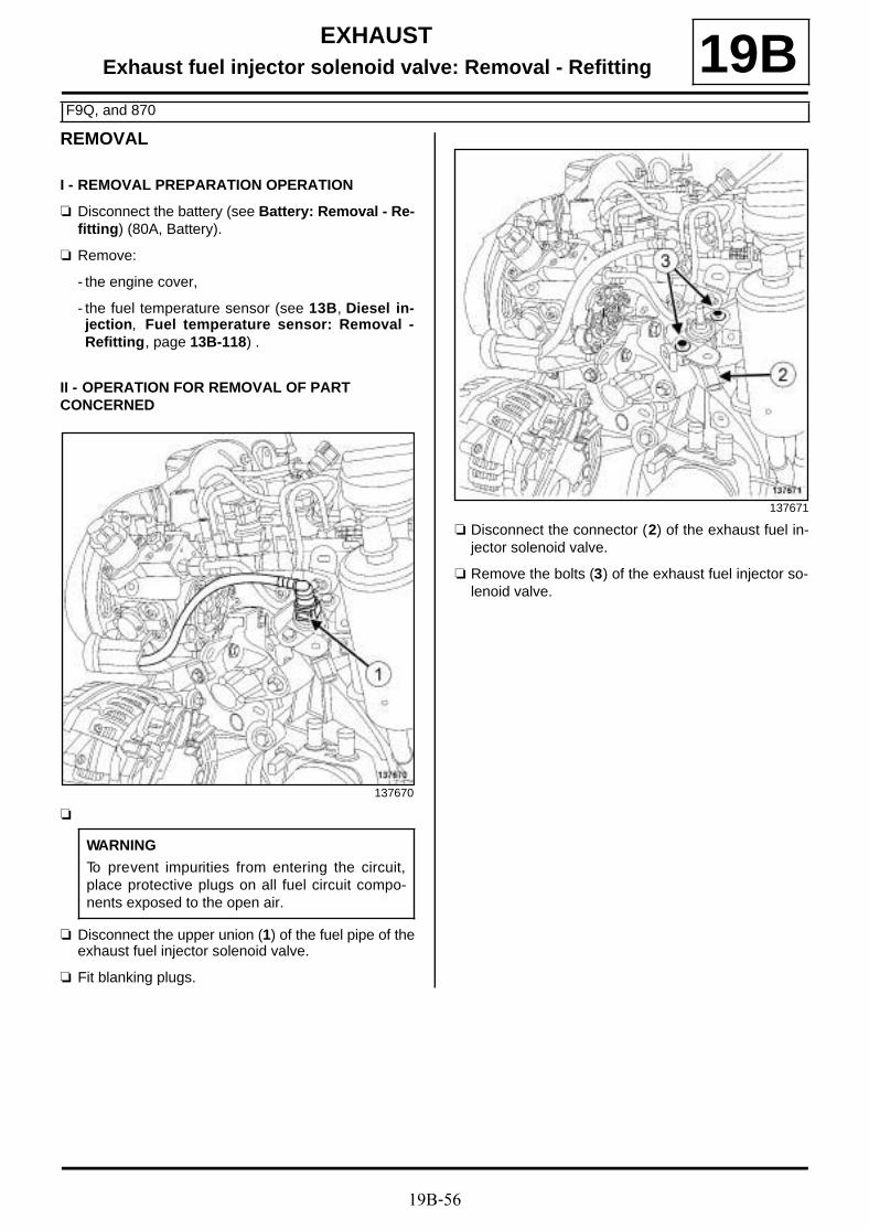
19B-56
EXHAUSTExhaust fuel injector solenoid valve: Removal - Refitting
F9Q, and 870
19BREMOVAL
I - REMOVAL PREPARATION OPERATION
a Disconnect the battery (see Battery: Removal - Re-fitting) (80A, Battery).
a Remove:
- the engine cover,
- the fuel temperature sensor (see 13B, Diesel in-jection, Fuel temperature sensor: Removal -Refitting, page 13B-118) .
II - OPERATION FOR REMOVAL OF PART CONCERNED
a
a Disconnect the upper union (1) of the fuel pipe of theexhaust fuel injector solenoid valve.
a Fit blanking plugs.
a Disconnect the connector (2) of the exhaust fuel in-jector solenoid valve.
a Remove the bolts (3) of the exhaust fuel injector so-lenoid valve.
137670
WARNING
To prevent impurities from entering the circuit,place protective plugs on all fuel circuit compo-nents exposed to the open air.
137671

19B-57
EXHAUSTExhaust fuel injector solenoid valve: Removal - Refitting
F9Q, and 870
19B
a
a Disconnect the lower union (4) of the fuel pipe of theexhaust fuel injector solenoid valve.
a Remove the exhaust fuel injector solenoid valve.
REFITTING
I - REFITTING PREPARATION OPERATION
a
II - REFITTING OPERATION FOR PART CONCERNED
a Remove the blanking plugs.
a Connect the lower union of the fuel pipe of the ex-haust fuel injector solenoid valve.
a Refit the exhaust fuel injector solenoid valve.
a Connect:
- the connector of the exhaust fuel injector solenoidvalve,
- the upper union of the fuel pipe of the exhaust fuelinjector solenoid valve.
III - FINAL OPERATION
a Refit:
- the fuel temperature sensor (see 13B, Diesel in-jection, Fuel temperature sensor: Removal -Refitting, page 13B-118) ,
- the engine cover.
a Connect the battery (see Battery: Removal - Refit-ting) .
137672
WARNING
To prevent impurities from entering the circuit,place protective plugs on all fuel circuit compo-nents exposed to the open air.
WARNING
Do not remove the blanking plugs from eachcomponent until the last moment.
Also, do not remove the components from theirpackaging until they are to be fitted to the vehi-cle.
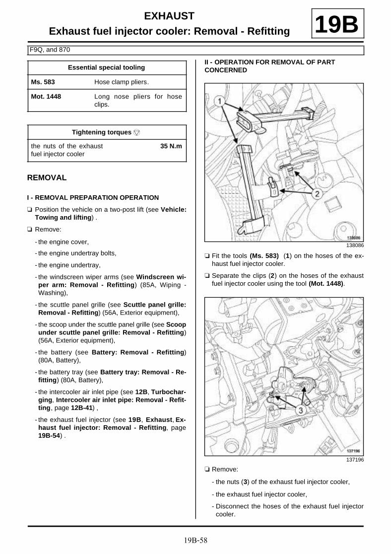
19B-58
EXHAUSTExhaust fuel injector cooler: Removal - Refitting
F9Q, and 870
19B
REMOVAL
I - REMOVAL PREPARATION OPERATION
a Position the vehicle on a two-post lift (see Vehicle:Towing and lifting) .
a Remove:
- the engine cover,
- the engine undertray bolts,
- the engine undertray,
- the windscreen wiper arms (see Windscreen wi-per arm: Removal - Refitting) (85A, Wiping -Washing),
- the scuttle panel grille (see Scuttle panel grille:Removal - Refitting) (56A, Exterior equipment),
- the scoop under the scuttle panel grille (see Scoopunder scuttle panel grille: Removal - Refitting)(56A, Exterior equipment),
- the battery (see Battery: Removal - Refitting)(80A, Battery),
- the battery tray (see Battery tray: Removal - Re-fitting) (80A, Battery),
- the intercooler air inlet pipe (see 12B, Turbochar-ging, Intercooler air inlet pipe: Removal - Refit-ting, page 12B-41) ,
- the exhaust fuel injector (see 19B, Exhaust, Ex-haust fuel injector: Removal - Refitting, page19B-54) .
II - OPERATION FOR REMOVAL OF PART CONCERNED
a Fit the tools (Ms. 583) (1) on the hoses of the ex-haust fuel injector cooler.
a Separate the clips (2) on the hoses of the exhaustfuel injector cooler using the tool (Mot. 1448).
a Remove:
- the nuts (3) of the exhaust fuel injector cooler,
- the exhaust fuel injector cooler,
- Disconnect the hoses of the exhaust fuel injectorcooler.
Essential special tooling
Ms. 583 Hose clamp pliers.
Mot. 1448 Long nose pliers for hoseclips.
Tightening torquesm
the nuts of the exhaustfuel injector cooler
35 N.m
138086
137196

19B-59
EXHAUSTExhaust fuel injector cooler: Removal - Refitting
F9Q, and 870
19BREFITTING
I - REFITTING OPERATION FOR PART CONCERNED
a Refit the exhaust fuel injector cooler.
a Torque tighten the nuts of the exhaust fuel injec-tor cooler (35 N.m).
a Connect the hoses to the exhaust fuel injector coo-ler.
a Fit the clips on the hoses of the exhaust fuel injectorcooler using the tool (Mot. 1448).
II - FINAL OPERATION
a Refit:
- the exhaust fuel injector (see 19B, Exhaust, Ex-haust fuel injector: Removal - Refitting, page19B-54) ,
- the intercooler air inlet pipe (see 12B, Turbochar-ging, Intercooler air inlet pipe: Removal - Refit-ting, page 12B-41) ,
- the battery tray (see Battery tray: Removal - Re-fitting) (80A, Battery),
- the battery (see Battery: Removal - Refitting)(80A, Battery),
- the scoop under the scuttle panel grille (see Scoopunder scuttle panel grille: Removal - Refitting)(56A, Exterior equipment),
- the scuttle panel grille (see Scuttle panel grille:Removal - Refitting) (56A, Exterior equipment),
- the windscreen wiper arms (see Windscreen wi-per arm: Removal - Refitting) (85A, Wiping -Washing),
- the engine undertray,
- the engine cover.
a Bleed the cooling system (see 19A, Cooling, Coo-ling circuit: Draining - Refilling, page 19A-17) .
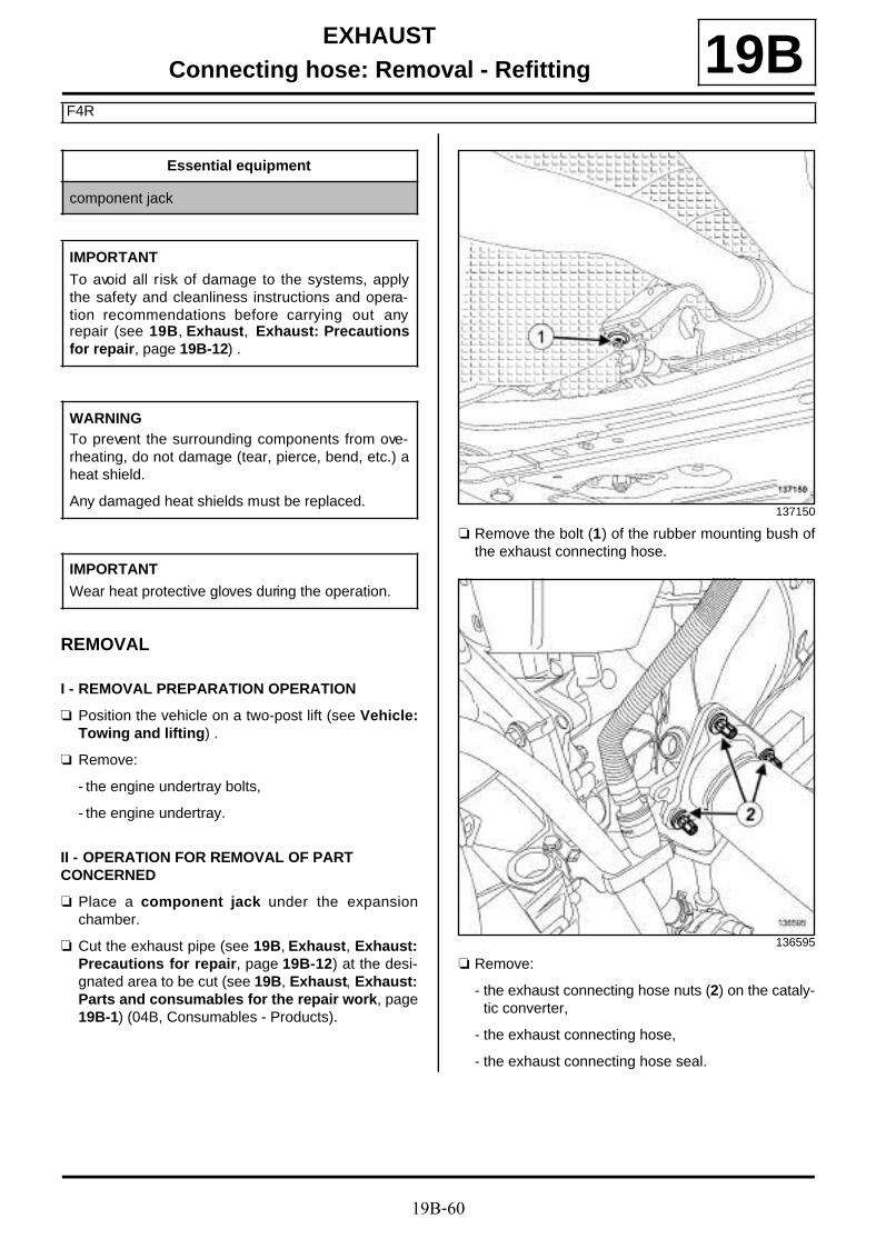
19B-60
EXHAUSTConnecting hose: Removal - Refitting
F4R
19B
REMOVAL
I - REMOVAL PREPARATION OPERATION
a Position the vehicle on a two-post lift (see Vehicle:Towing and lifting) .
a Remove:
- the engine undertray bolts,
- the engine undertray.
II - OPERATION FOR REMOVAL OF PART CONCERNED
a Place a component jack under the expansionchamber.
a Cut the exhaust pipe (see 19B, Exhaust, Exhaust:Precautions for repair, page 19B-12) at the desi-gnated area to be cut (see 19B, Exhaust, Exhaust:Parts and consumables for the repair work, page19B-1) (04B, Consumables - Products).
a Remove the bolt (1) of the rubber mounting bush ofthe exhaust connecting hose.
a Remove:
- the exhaust connecting hose nuts (2) on the cataly-tic converter,
- the exhaust connecting hose,
- the exhaust connecting hose seal.
Essential equipment
component jack
IMPORTANT
To avoid all risk of damage to the systems, applythe safety and cleanliness instructions and opera-tion recommendations before carrying out anyrepair (see 19B, Exhaust, Exhaust: Precautionsfor repair, page 19B-12) .
WARNINGTo prevent the surrounding components from ove-rheating, do not damage (tear, pierce, bend, etc.) aheat shield.
Any damaged heat shields must be replaced.
IMPORTANT
Wear heat protective gloves during the operation.
137150
136595

19B-61
EXHAUSTConnecting hose: Removal - Refitting
F4R
19BREFITTING
I - REFITTING PREPARATION OPERATION
a parts always to be replaced: seal between cata-lytic converter and exhaust downpipe hose (10,08,02,21).
a Use SURFACE CLEANER (see Vehicle: Partsand ingredients for the repairwork) (04B, Consu-mables - Products) to clean the bearing faces of thecatalytic converter and the exhaust connecting ho-se.
II - REFITTING OPERATION FOR PART CONCERNED
a Refit:
- a new seal on the exhaust connecting hose,
- the exhaust connecting hose,
- the exhaust connecting hose nuts,
- the bolt of the rubber mounting bush of the exhaustconnecting hose.
a Fit a new After-Sales sleeve between the expansionchamber and the connecting hose (see 19B, Ex-haust, Exhaust: Parts and consumables for therepair work, page 19B-1) .
a Tighten the sleeve while supporting the exhaust pipeto ensure they are aligned.
III - FINAL OPERATION
a Check:
- that all the exhaust pipe heat shields are in placeand properly attached.
- that there is no contact with the underbody,
- that there are no leaks.
a Refit the engine undertray.
IMPORTANT
Position the « nut and bolt securing the sleeve »assembly so that the assembly cannot come intocontact with the underbody.

19B-62
EXHAUSTConnecting hose: Removal - Refitting
F9Q, and 870
19Ba The connecting hose is not sold separately in the
Parts Department. To replace it, the particle filtermust be replaced (see 19B, Exhaust, Particle fil-ter: Removal - Refitting, page 19B-47) .

19C-1
TANKFuel tank: Draining 19C
DRAINING
I - DRAINING PREPARATION OPERATION
a Disconnect the battery (see Battery: Removal - Re-fitting) (80A, Battery).
II - DRAINING OPERATION
a Unclip the manual fuel priming pump at (1) .
a Disconnect the fuel supply pipe union (2) from themanual fuel priming pump.
Essential special tooling
Mot. 1311-08 Union for measuring fuelpressure.
Essential equipment
pneumatic transfer pump for fuels
IMPORTANT
During this operation, be sure to:
- refrain from smoking or bringing red hot objectsclose to the working area,
- be careful of fuel splashes when disconnecting theunion.
IMPORTANT
Wear leaktight gloves (Nitrile type) for this opera-tion.
IMPORTANT
Wear goggles with side protectors for this opera-tion.
WARNING
To prevent impurities from entering the circuit, placeprotective plugs on all fuel circuit componentsexposed to the open air.
WARNING
To avoid any corrosion or damage, protect theareas on which fuel is likely to run.
F9Q or K9K
137737
137738

19C-2
TANKFuel tank: Draining 19C
a Connect the pneumatic transfer pump for fuels onthe fuel supply pipe of the fuel priming pump.
a Remove the front engine cover.
a Disconnect the fuel supply pipe union from the injec-tor rail.
a Fit a « T » union (Mot. 1311-08) (3) .
a Connect a pneumatic transfer pump for fuels tothe « T » union outlet.
a Remove the front engine cover.
a Disconnect the fuel supply pipe union from the injec-tor rail.
a Fit a « T » union (Mot. 1311-08) (4) .
99641
F4R
137772
99641
K4M
137771

19C-3
TANKFuel tank: Draining 19C
a Connect a pneumatic transfer pump for fuels tothe « T » union outlet.
a Drain the fuel tank.
REFITTING
a Disconnect the pneumatic transfer pump for fuelsfrom the fuel supply pipe of the manual fuel primingpump.
a Connect the fuel supply pipe on the manual fuel pri-ming pump.
a Refit the manual fuel priming pump.
a Disconnect the pneumatic transfer pump for fuelsfrom the « T » union outlet.
a Remove the « T » union (Mot. 1311-08).
a Connect the fuel supply union on the injector rail.
a Refit the engine cover.
a Connect the battery (see Battery: Removal - Refit-ting) (80A, Battery).
99641
F9Q or K9K
F4R or K4M

19C-4
TANKFuel tank: Removal - Refitting 19C
REMOVAL
I - REMOVAL PREPARATION OPERATION
a Position the vehicle on a two-post lift (see Vehicle:Towing and lifting) (02A, Lifting equipment).
a Disconnect the battery (see Battery : Removal -Refitting) (80A, Battery).
a Drain the fuel tank (see 19C, Tank, Fuel tank: Drai-ning , page 19C-1) .
a Raise the rear bench seat.
a Remove:
- the subframe panel bolts (1) ,
- the subframe panel,
- the plastic blanking cover of the passenger com-partment.
Essential special tooling
Mot. 1352 Plastic fuel pipe cutter.
Essential equipment
component support
Tightening torquesm
fuel tank bolts 21 N.m
rear heat shield bolts 21 N.m
IMPORTANT
During this operation, be sure to:
- refrain from smoking or bringing red hot objectsclose to the working area,
- be careful of fuel splashes when disconnecting theunion.
IMPORTANT
Wear leaktight gloves (Nitrile type) for this opera-tion.
IMPORTANT
Wear goggles with side protectors for this opera-tion.
WARNING
To avoid any corrosion or damage, protect theareas on which fuel is likely to run.
WARNING
To prevent impurities from entering the circuit, placeprotective plugs on all fuel circuit componentsexposed to the open air.
WARNING
To prevent the surrounding components from ove-rheating, do not damage (tear, pierce, bend, etc.) aheat shield.
Any damaged heat shields must be replaced.
138147

19C-5
TANKFuel tank: Removal - Refitting 19C
a Disconnect:
- the fuel level sensor module connector (2) ,
- the fuel pipe unions (3) on the fuel level sensor mo-dule.
a Unclip the fuel level sensor module connector (4) .
a Disconnect:
- the fuel level sensor module connectors (4) and (5),
- the fuel pipe union (6) on the fuel level sensor mo-dule.
a Remove:
- the silencer (see 19B, Exhaust, Silencer: Remo-val - Refitting, page 19B-40) .
- the connector pipe (see 19B, Exhaust, Connectorpipe: Removal - Refitting, page 19B-35) .
F9Q or K9K
137742
F4R or K4M
138145
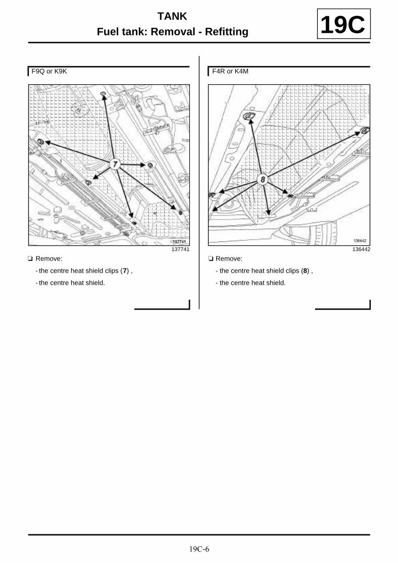
19C-6
TANKFuel tank: Removal - Refitting 19C
a Remove:
- the centre heat shield clips (7) ,
- the centre heat shield.
a Remove:
- the centre heat shield clips (8) ,
- the centre heat shield.
F9Q or K9K
137741
F4R or K4M
136442

19C-7
TANKFuel tank: Removal - Refitting 19C
a Remove:
- the rear heat shield bolts (9) ,
- the rear heat shield.
a Remove:
- the rear heat shield bolts (10) ,
- the rear heat shield.
a Remove the clip (11) from the « filler neck - fueltank » connecting hose on the fuel tank side.
a Disconnect the anti-return pipe union (12) .
F9Q or K9K
137733
F4R or K4M
136447
136434

19C-8
TANKFuel tank: Removal - Refitting 19C
a Unclip the rigid brake pipes (13) .
a Move the rigid brake pipes slightly to one side.
F9Q or K9K
137732
137734
137735

19C-9
TANKFuel tank: Removal - Refitting 19C
a Unclip the rigid brake pipes (14) .
a Move the rigid brake pipes slightly to one side.
a Unclip the fuel pipes (15) from the fuel tank.
a Move the fuel pipesto one side.
F4R or K4M
136425
136419
136430
F9Q or K9K
137735

19C-10
TANKFuel tank: Removal - Refitting 19C
a For vehicles equipped with a tank which has an off-set breather (tank with a breather pipe going fromthe tank to the wheel arch), disconnect the offsetbreather pipe (16) from the fuel tank.
a Unclip the fuel pipes (17) from the fuel tank.
a Move the fuel pipesto one side.
a Disconnect the union of the fuel vapour absorberoutlet pipe (18) .
a Move aside the fuel vapour absorber outlet pipe.
137977
F4R or K4M
136419
136432

19C-11
TANKFuel tank: Removal - Refitting 19C
II - OPERATION FOR REMOVAL OF PART CONCERNED
a Disconnect the filler neck hose at the fuel tank end.
a Fit a component support under the fuel tank.
a Remove:
- the fuel tank bolts (19) ,
- the fuel tank.
If the fuel tank is being replaced
a Remove the fuel level sensor module (see 19C,Tank, Fuel level sensor module: Removal - Refit-ting, page 19C-16) .
REFITTING
I - REFITTING PREPARATION OPERATION
a parts always to be replaced: Fuel pipe clipbetween the fuel tank filler neck and the fuel tank(11,08,01,05).
If the fuel tank is being replaced
a Refit the fuel level sensor module (see 19C, Tank,Fuel level sensor module: Removal - Refitting,page 19C-16) .
136423
136415

19C-12
TANKFuel tank: Removal - Refitting 19C
a For vehicles equipped with a tank which does nothave an offset breather (tank without a breather pipegoing from the tank to the wheel arch), the new tankmust be adapted by cutting the breather pipe at (A)with the tool (Mot. 1352).
II - REFITTING OPERATION FOR PART CONCERNED
a Refit the fuel tank.
a Torque tighten the fuel tank bolts (21 N.m).
a Connect the filler neck hose to the fuel tank.
a For vehicles equipped with a tank which has an off-set breather (tank with a breather pipe going fromthe tank to the wheel arch), connect the offset brea-ther pipe of the fuel tank.
III - FINAL OPERATION
a Remove the component support.
a Fit the fuel vapour absorber outlet pipe.
a Connect the union of the fuel vapour absorber outletpipe.
a Position the fuel pipes.
a Clip the fuel supply pipes onto the fuel tank.
a Fit the rigid brake pipes.
a Clip on the rigid brake pipes.
a Connect the anti-return pipe union.
a Refit a new clip on the fuel tank end of the « fillerneck - fuel tank » connecting hose.
a Refit the rear heat shield.
a Torque tighten the rear heat shield bolts (21 N.m).
F9Q or K9K
138085
F9Q or K9K
F4R or K4M

19C-13
TANKFuel tank: Removal - Refitting 19C
a Refit:
- the central heat shield,
- the centre heat shield clips,
- the connector pipe (see 19B, Exhaust, Connectorpipe: Removal - Refitting, page 19B-35) ,
- the silencer (see 19B, Exhaust, Silencer: Remo-val - Refitting, page 19B-40) .
a Connect:
- the fuel pipe unions on the fuel level sensor modu-le,
- the fuel level sensor module connector.
a Connect:
- the fuel pipe union on the fuel level sensor module,
- the fuel level sensor module connectors.
a Clip on the fuel level sensor module connector.
a Refit:
- the plastic blanking cover of the passenger com-partment,
- the subframe panel.
a Refit the rear bench seat.
a Connect the battery (see Battery : Removal - Refit-ting) (80A, Battery).
F9Q or K9K
F4R or K4M

19C-14
TANKFiller neck: Removal - Refitting 19C
REMOVAL
I - REMOVAL PREPARATION OPERATION
a Position the vehicle on a two-post lift (see Vehicle:Towing and lifting) (02A, Lifting equipment).
a Disconnect the battery (see Battery: Removal - Re-fitting) (80A, Battery).
a Drain the fuel tank (see 19C, Tank, Fuel tank: Drai-ning , page 19C-1) .
a Open the fuel tank flap.
a Remove:
- the bolts (1) from the filler neck on the fuel tankflap,
- the rear right-hand wheel (see Wheel: Removal -Refitting) (35A, Wheels and tyres),
- the rear right-hand wheel arch liner (see Rearwheel arch liner: Removal - Refitting) (55A, Ex-terior protection).
Tightening torquesm
filler neck earth bolts 21 N.m
IMPORTANT
During this operation, be sure to:
- refrain from smoking or bringing red hot objectsclose to the working area,
- be careful of fuel splashes when disconnecting theunion.
IMPORTANT
Wear goggles with side protectors for this opera-tion.
IMPORTANT
Wear leaktight gloves (Nitrile type) for this opera-tion.
WARNING
To avoid any corrosion or damage, protect theareas on which fuel is likely to run.
WARNING
Keep the pipe unions away from contaminatedareas.
WARNING
To prevent impurities from entering the circuit, placeprotective plugs on all fuel circuit componentsexposed to the open air.
137736

19C-15
TANKFiller neck: Removal - Refitting 19C
II - OPERATION FOR REMOVAL OF PART CONCERNED
a Remove the earth bolts (2) from the filler neck.
a Disconnect the anti-return pipe .
a Remove the clip (3) from the « filler neck - fuel tank »connecting hose on the fuel tank side.
a Disconnect the filler neck hose from the fuel tank.
a Remove the filler neck.
REFITTING
I - REFITTING PREPARATION OPERATION
a parts always to be replaced: Fuel pipe clipbetween the fuel tank filler neck and the fuel tank(11,08,01,05).
II - REFITTING OPERATION FOR PART CONCERNED
a Refit the filler neck.
a Connect the filler neck hose to the fuel tank.
a Refit a new clip on the « filler neck - fuel tank » con-necting hose.
a Disconnect the anti-return pipe.
a Refit the earth bolts on the filler neck.
a Torque tighten the filler neck earth bolts (21 N.m).
III - FINAL OPERATION
a Refit:
- the rear right-hand wheel arch liner (see Rearwheel arch liner: Removal - Refitting) (55A, Ex-terior protection),
- the rear right-hand wheel (see Wheel: Removal -Refitting) (35A, Wheels and tyres),
- the filler neck bolts on the fuel tank flap.
a Connect the battery (see Battery: Removal - Refit-ting) (80A, Battery).
136440
136434

19C-16
TANKFuel level sensor module: Removal - Refitting 19C
REMOVAL
I - REMOVAL PREPARATION OPERATION
a Position the vehicle on the two-post lift (see Vehicle:Towing and lifting) (02A, Lifting equipment).
a Disconnect the battery (see Battery: Removal - Re-fitting) (80A, Battery).
a Drain the fuel tank (see 19C, Tank, Fuel tank: Drai-ning, page 19C-1) .
a Raise the rear bench seat.
a Remove:
- the subframe panel bolts (1) ,
- the subframe panel,
- the plastic blanking cover of the passenger com-partment.
Essential special tooling
Mot. 1397 Universal petrol tank gaugenut wrench.
IMPORTANT
During this operation, be sure to:
- refrain from smoking or bringing red hot objectsclose to the working area,
- be careful of fuel splashes when disconnecting theunion.
IMPORTANT
Wear leaktight gloves (Nitrile type) for this opera-tion.
IMPORTANT
Wear goggles with side protectors for this opera-tion.
WARNING
To prevent impurities from entering the circuit, placeprotective plugs on all fuel circuit componentsexposed to the open air.
WARNING
Keep the pipe unions away from contaminatedareas.
138147

19C-17
TANKFuel level sensor module: Removal - Refitting 19C
II - OPERATION FOR REMOVAL OF PART CONCERNED
a Disconnect:
- the fuel level sensor module connector (2) ,
- the fuel pipe unions (3) from the fuel level sensormodule.
a Unclip the fuel level sensor module connector (4) .
a Disconnect:
- the fuel level sensor module connectors (4) and (5),
- the fuel pipe union (6) from the fuel level sensormodule.
F9Q or K9K
137742
F4R or K4M
138145

19C-18
TANKFuel level sensor module: Removal - Refitting 19C
a Remove the fuel level sensor module nut (7) usingthe tool (Mot. 1397).
a Let the fuel drain from the fuel level sensor module.
a Remove:
- the fuel level sensor module, taking care not to da-mage the float,
- the fuel level sensor module seal.
REFITTING
I - REFITTING PREPARATION OPERATION
a parts always to be replaced: Fuel level sensormodule nut (11,08,02,05).
a parts always to be replaced: Fuel level sensormodule seal (11,08,02,06).
II - REFITTING OPERATION FOR PART CONCERNED
a Position:
- the new seal (8) in the neck correctly,
- the fuel level sensor module (9) on the fuel tank. Alug on the fuel level sensor module and a recess inthe fuel tank ensure correct positioning in the fueltank.
a Use a hand to press the fuel level sensor module togrip the seal.
a Refit a new nut on the fuel tank.
138143
WARNING
To prevent the tank from deforming, refit the fuelsender unit nut to the tank well immediately.
118996
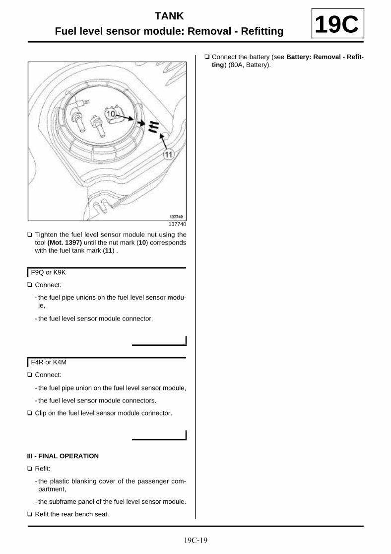
19C-19
TANKFuel level sensor module: Removal - Refitting 19C
a Tighten the fuel level sensor module nut using thetool (Mot. 1397) until the nut mark (10) correspondswith the fuel tank mark (11) .
a Connect:
- the fuel pipe unions on the fuel level sensor modu-le,
- the fuel level sensor module connector.
a Connect:
- the fuel pipe union on the fuel level sensor module,
- the fuel level sensor module connectors.
a Clip on the fuel level sensor module connector.
III - FINAL OPERATION
a Refit:
- the plastic blanking cover of the passenger com-partment,
- the subframe panel of the fuel level sensor module.
a Refit the rear bench seat.
a Connect the battery (see Battery: Removal - Refit-ting) (80A, Battery).
137740
F9Q or K9K
F4R or K4M

19D-1
ENGINE MOUNTINGLeft-hand suspended engine mounting: Removal - Refitting
F9Q
19D
REMOVAL
I - REMOVAL PREPARATION OPERATION
a Position the vehicle on a two-post lift (see Vehicle:Towing and lifting) (02A, Lifting equipment).
a Remove:
- the engine cover,
- the engine undertray bolts,
- the engine undertray,
- the windscreen wiper arms (see Windscreen wi-per arm: Removal - Refitting) (85A, Wiping -Washing),
- the scuttle panel grille (see Scuttle panel grille:Removal - Refitting) (56A, Exterior equipment),
- the scoop under the scuttle panel grille (see Scoopunder scuttle panel grille: Removal - Refitting)(56A, Exterior equipment),
- the battery (see Battery : Removal - Refitting)(80A, Battery),
- the battery tray (see Battery tray: Removal - Re-fitting) (80A, Battery),
- the air filter unit (see 12A, Fuel mixture, Air filterunit: Removal - Refitting, page 12A-4) ,
- the lower engine tie-bar (see 19D, Engine moun-ting, Lower engine tie-bar: Removal - Refitting,page 19D-33) .
a Remove the front left-hand bonnet stop (1) .
a Position the (Mot. 1453) and (Mot. 1453-01) (2) .
a Mark the position of the left-hand suspended enginemounting on the body.
Essential special tooling
Mot. 1453 Multiple-adjusting enginemounting support with retai-ning straps.
Mot. 1453-01 Additional winder nut onengine lift support Mot. 1453.
Tightening torquesm
gearbox mounting boltson the suspendedengine mounting
62 N.m
bolts of the suspendedengine mounting sup-port on the body
62 N.m
central bolt for the sus-pended engine moun-ting rubber pad support
105 N.m134172
134174
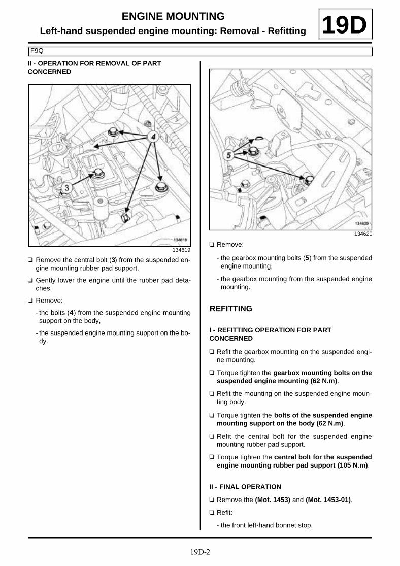
19D-2
ENGINE MOUNTINGLeft-hand suspended engine mounting: Removal - Refitting
F9Q
19DII - OPERATION FOR REMOVAL OF PART CONCERNED
a Remove the central bolt (3) from the suspended en-gine mounting rubber pad support.
a Gently lower the engine until the rubber pad deta-ches.
a Remove:
- the bolts (4) from the suspended engine mountingsupport on the body,
- the suspended engine mounting support on the bo-dy.
a Remove:
- the gearbox mounting bolts (5) from the suspendedengine mounting,
- the gearbox mounting from the suspended enginemounting.
REFITTING
I - REFITTING OPERATION FOR PART CONCERNED
a Refit the gearbox mounting on the suspended engi-ne mounting.
a Torque tighten the gearbox mounting bolts on thesuspended engine mounting (62 N.m).
a Refit the mounting on the suspended engine moun-ting body.
a Torque tighten the bolts of the suspended enginemounting support on the body (62 N.m).
a Refit the central bolt for the suspended enginemounting rubber pad support.
a Torque tighten the central bolt for the suspendedengine mounting rubber pad support (105 N.m).
II - FINAL OPERATION
a Remove the (Mot. 1453) and (Mot. 1453-01).
a Refit:
- the front left-hand bonnet stop,
134619
134620

19D-3
ENGINE MOUNTINGLeft-hand suspended engine mounting: Removal - Refitting
F9Q
19D- the lower engine tie-bar (see 19D, Engine moun-ting, Lower engine tie-bar: Removal - Refitting,page 19D-33) ,
- the air filter unit (see 12A, Fuel mixture, Air filterunit: Removal - Refitting, page 12A-4) ,
- the battery tray (see Battery tray: Removal - Re-fitting) (80A, Battery),
- the battery (see Battery : Removal - Refitting)(80A, Battery),
- the scoop under the scuttle panel grille (see Scoopunder scuttle panel grille: Removal - Refitting)(56A, Exterior equipment),
- the scuttle panel grille (see Scuttle panel grille:Removal - Refitting) (56A, Exterior equipment),
- the windscreen wiper arms (see Windscreen wi-per arm: Removal - Refitting) (85A, Wiping -Washing),
- the engine undertray,
- the engine cover.

19D-4
ENGINE MOUNTINGLeft-hand suspended engine mounting: Removal - Refitting
K4M
19D
REMOVAL
I - REMOVAL PREPARATION OPERATION
a Position the vehicle on a two-post lift (see Vehicle:Towing and lifting) (02A, Lifting equipment).
a Remove:
- the engine cover,
- the windscreen wiper arms (see Windscreen wi-per arm: Removal - Refitting) (85A, Wiping -Washing),
- the scuttle panel grille (see Scuttle panel grille:Removal - Refitting) (56A, Exterior equipment),
- the scoop under the scuttle panel grille (see Scoopunder scuttle panel grille: Removal - Refitting)(56A, Exterior equipment),
- the battery (see Battery: Removal - Refitting)(80A, Battery),
- the battery tray (see Battery tray: Removal - Re-fitting) (80A, Battery),
- the air filter unit (see 12A, Fuel mixture, Air filterunit: Removal - Refitting, page 12A-4) ,
- the lower engine tie-bar (see 19D, Engine moun-ting, Lower engine tie-bar: Removal - Refitting,page 19D-33) .
a Unclip the battery wiring channel (1) .
a Move aside the battery wiring channel.
a Unclip the engine wiring at (2) .
Essential special tooling
Mot. 1453 Multiple-adjusting enginemounting support with retai-ning straps.
Mot. 1453-01 Additional winder nut onengine lift support Mot. 1453.
Tightening torquesm
left-hand suspendedengine mounting rubberpad support bolts
62 Nm
bolts for the suspendedengine mounting rubberpad cover
62 N.m
central bolt for the left-hand suspended enginemounting rubber padsupport
62 N.m135947
135932

19D-5
ENGINE MOUNTINGLeft-hand suspended engine mounting: Removal - Refitting
K4M
19D
a Unclip the hydraulic clutch pipe from the left-handsuspended engine mounting cover at (3) .
a Fit the (Mot. 1453) fitted with the (Mot. 1453-01).
II - OPERATION FOR REMOVAL OF PART CONCERNED
a Remove the central bolt (4) from the support of theleft-hand suspended engine mounting rubber pad.
a Gently lower the engine until the rubber pad deta-ches.
a Remove:
- the bolts (5) for the left-hand suspended enginemounting rubber pad cover,
K4M, and 858 or 866
136622
135935
135948
K4M, and 848
135931
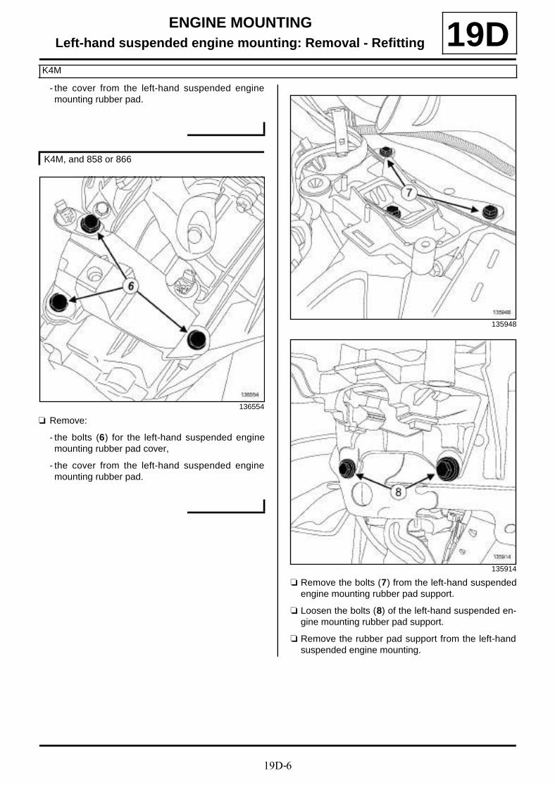
19D-6
ENGINE MOUNTINGLeft-hand suspended engine mounting: Removal - Refitting
K4M
19D- the cover from the left-hand suspended enginemounting rubber pad.
a Remove:
- the bolts (6) for the left-hand suspended enginemounting rubber pad cover,
- the cover from the left-hand suspended enginemounting rubber pad.
a Remove the bolts (7) from the left-hand suspendedengine mounting rubber pad support.
a Loosen the bolts (8) of the left-hand suspended en-gine mounting rubber pad support.
a Remove the rubber pad support from the left-handsuspended engine mounting.
K4M, and 858 or 866
136554
135948
135914

19D-7
ENGINE MOUNTINGLeft-hand suspended engine mounting: Removal - Refitting
K4M
19DREFITTING
I - REFITTING OPERATION FOR PART CONCERNED
a Refit the rubber pad support for the left-hand sus-pended engine mounting.
a Torque tighten the left-hand suspended enginemounting rubber pad support bolts (62 Nm).
a Refit the cover for the left-hand suspended enginemounting.
a Torque tighten the bolts for the suspended enginemounting rubber pad cover (62 N.m).
a Refit the central bolt for the left-hand suspended en-gine mounting rubber pad support.
a Torque tighten the central bolt for the left-handsuspended engine mounting rubber pad support(62 N.m).
II - FINAL OPERATION
a Remove the (Mot. 1453) fitted with the (Mot. 1453-01).
a Clip the hydraulic clutch pipe onto the cover of theleft-hand suspended engine mounting.
a Clip on the engine wiring.
a Fit the battery wiring channel.
a Clip on the battery wiring channel.
a Refit:
- the lower engine tie-bar (see 19D, Engine moun-ting, Lower engine tie-bar: Removal - Refitting,page 19D-33) ,
- the air filter unit (see 12A, Fuel mixture, Air filterunit: Removal - Refitting, page 12A-4) ,
- the battery tray (see Battery tray: Removal - Re-fitting) (80A, Battery),
- the battery (see Battery: Removal - Refitting)(80A, Battery),
- the scoop under the scuttle panel grille (see Scoopunder scuttle panel grille: Removal - Refitting)(56A, Exterior equipment),
- the scuttle panel grille (see Scuttle panel grille:Removal - Refitting) (56A, Exterior equipment),
- the windscreen wiper arms (see Windscreen wi-per arm: Removal - Refitting) (85A, Wiping -Washing),
- the engine cover.
K4M, and 858 or 866

19D-8
ENGINE MOUNTINGLeft-hand suspended engine mounting: Removal - Refitting
K9K
19D
REMOVAL
I - REMOVAL PREPARATION OPERATION
a Position the vehicle on a two-post lift (see Vehicle:Towing and lifting) (02A, Lifting equipment).
a Remove:
- the battery (see Battery : Removal - Refitting)(80A, Battery),
- the battery tray (see Battery tray: Removal - Re-fitting) (80A, Battery),
- the air filter unit (see 12A, Fuel mixture, Air filterunit: Removal - Refitting, page 12A-4) ,
- the engine undertray bolts,
- the engine undertray.
a Remove:
- the bolts (1) from the lower engine tie-bar,
- the lower engine tie-bar.
a Remove the lower engine tie-bar (see 19D, Enginemounting, Lower engine tie-bar: Removal - Refit-ting, page 19D-33) .
a Remove:
- the windscreen wiper arms (see Windscreen wi-per arm: Removal - Refitting) (85A, Wiping -Washing),
- the scuttle panel grille (see Scuttle panel grille:Removal - Refitting) (56A, Exterior equipment),
Essential special tooling
Ms. 583 Hose clamp pliers.
Mot. 1453 Multiple-adjusting enginemounting support with retai-ning straps.
Mot. 1453-01 Additional winder nut onengine lift support Mot. 1453.
Essential equipment
safety strap(s)
indelible pencil
Tightening torquesm
support bolts for the left-hand suspended enginemounting on the gear-box
62 N.m
support bolts for the left-hand suspended enginemounting on the body
62 N.m
support bolt for the left-hand suspended enginemount ing on thegearbox62
N.m
upper engine tie-bar bolton the engine
115 N.m
upper engine tie-bar bolton the body
105 N.m
lower engine tie-bar bolton the subframe
180 N.m
lower engine tie-bar bolton the lower engine tie-bar support
180 N.m
K9K, and 832
134223
K9K, and 830 or 834

19D-9
ENGINE MOUNTINGLeft-hand suspended engine mounting: Removal - Refitting
K9K
19D- the scoop under the scuttle panel grille (see Scoopunder scuttle panel grille: Removal - Refitting)(56A, Exterior equipment).
a Remove:
- the upper engine tie-bar bolts (2) ,
- the upper engine tie-bar,
a Unclip the battery wiring channel from the left-handsuspended engine mounting (3) .
a Remove the battery wiring channel from the left-hand suspended engine mounting.
a Fit the tool (Ms. 583) (4) onto the clutch master cy-linder supply hose.
a Disconnect the hydraulic clutch pipe from the clutchmaster cylinder by pulling on the clip (5) .
K9K, and 832
134221
135506
134486

19D-10
ENGINE MOUNTINGLeft-hand suspended engine mounting: Removal - Refitting
K9K
19D
a Disconnect the hydraulic clutch pipe from the hy-draulic clutch release bearing by pulling on the clips(6) .
a Fit suitable blanking plugs on:
- the opening of the hydraulic clutch release bearing,
- the openings of the hydraulic clutch pipe,
- the opening of the clutch master cylinder.
a Unclip the hydraulic clutch pipe from the left-handsuspended engine mounting at (7) .
135470
K9K, and 832
135469
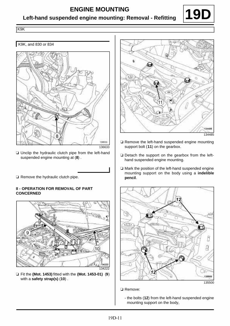
19D-11
ENGINE MOUNTINGLeft-hand suspended engine mounting: Removal - Refitting
K9K
19D
a Unclip the hydraulic clutch pipe from the left-handsuspended engine mounting at (8) .
a Remove the hydraulic clutch pipe.
II - OPERATION FOR REMOVAL OF PART CONCERNED
a Fit the (Mot. 1453) fitted with the (Mot. 1453-01) (9)with a safety strap(s) (10) .
a Remove the left-hand suspended engine mountingsupport bolt (11) on the gearbox.
a Detach the support on the gearbox from the left-hand suspended engine mounting.
a Mark the position of the left-hand suspended enginemounting support on the body using a indeliblepencil.
a Remove:
- the bolts (12) from the left-hand suspended enginemounting support on the body,
K9K, and 830 or 834
136633
134222
134485
135500
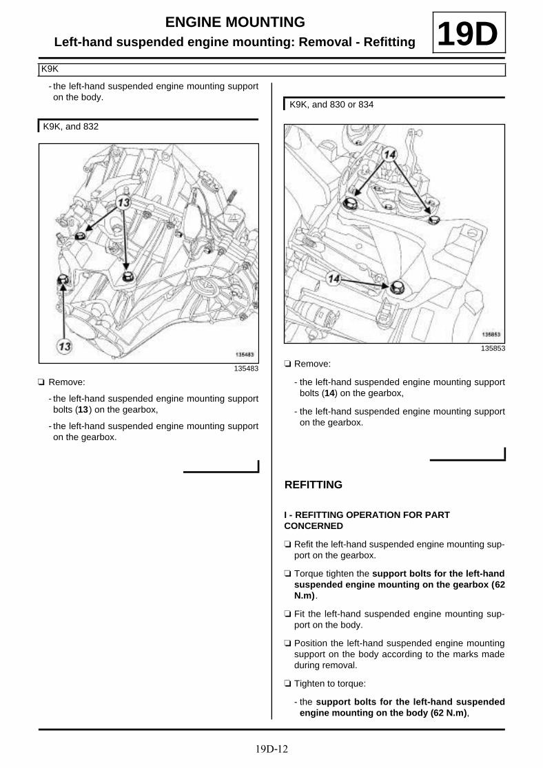
19D-12
ENGINE MOUNTINGLeft-hand suspended engine mounting: Removal - Refitting
K9K
19D- the left-hand suspended engine mounting supporton the body.
a Remove:
- the left-hand suspended engine mounting supportbolts (13) on the gearbox,
- the left-hand suspended engine mounting supporton the gearbox.
a Remove:
- the left-hand suspended engine mounting supportbolts (14) on the gearbox,
- the left-hand suspended engine mounting supporton the gearbox.
REFITTING
I - REFITTING OPERATION FOR PART CONCERNED
a Refit the left-hand suspended engine mounting sup-port on the gearbox.
a Torque tighten the support bolts for the left-handsuspended engine mounting on the gearbox (62N.m).
a Fit the left-hand suspended engine mounting sup-port on the body.
a Position the left-hand suspended engine mountingsupport on the body according to the marks madeduring removal.
a Tighten to torque:
- the support bolts for the left-hand suspendedengine mounting on the body (62 N.m),
K9K, and 832
135483
K9K, and 830 or 834
135853

19D-13
ENGINE MOUNTINGLeft-hand suspended engine mounting: Removal - Refitting
K9K
19D- the support bolt for the left-hand suspended en-gine mounting on the gearbox62 (N.m).
a Remove:
- the safety strap(s) from the (Mot. 1453),
- the (Mot. 1453) fitted with the (Mot. 1453-01).
II - FINAL OPERATION
a Refit the hydraulic clutch pipe.
a Clip the hydraulic clutch pipe onto the left suspen-ded engine mounting.
a Remove the blanking plugs from:
- the opening of the clutch master cylinder,
- the openings of the hydraulic clutch pipe,
- the opening of the hydraulic clutch release bearing.
a Connect the hydraulic clutch pipe to:
- the hydraulic clutch release bearing,
- the clutch master cylinder.
a Remove the tool (Ms. 583) from the clutch mastercylinder supply hose.
a Bleed the hydraulic clutch circuit (see Clutch cir-cuit: Bleeding) (37A, Mechanical component con-trols).
a Clip the battery wiring channel onto the left-handsuspended engine mounting.
a Refit the upper engine tie-bar.
a Tighten to torque:
- the upper engine tie-bar bolt on the engine (115N.m),
- the upper engine tie-bar bolt on the body (105N.m).
a Refit:
- the scoop under the scuttle panel grille (see Scoopunder scuttle panel grille: Removal - Refitting)(56A, Exterior equipment),
- the scuttle panel grille (see Scuttle panel grille:Removal - Refitting) (56A, Exterior equipment),
- the windscreen wiper arms (see Windscreen wi-per arm: Removal - Refitting) (85A, Wiping -Washing).
a Refit the lower engine tie-bar.
a Tighten to torque:
- the lower engine tie-bar bolt on the subframe(180 N.m),
- the lower engine tie-bar bolt on the lower engi-ne tie-bar support (180 N.m).
a Refit the lower engine tie-bar (see 19D, Enginemounting, Lower engine tie-bar: Removal - Refit-ting, page 19D-33) .
a Refit:
- the engine undertray,
- the air filter unit (see 12A, Fuel mixture, Air filterunit: Removal - Refitting, page 12A-4) ,
- the battery tray (see Battery tray: Removal - Re-fitting) (80A, Battery),
- the battery (see Battery : Removal - Refitting)(80A, Battery).
K9K, and 832
K9K, and 832
K9K, and 830 or 834
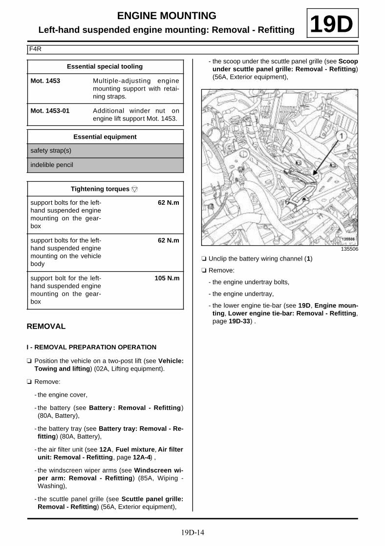
19D-14
ENGINE MOUNTINGLeft-hand suspended engine mounting: Removal - Refitting
F4R
19D
REMOVAL
I - REMOVAL PREPARATION OPERATION
a Position the vehicle on a two-post lift (see Vehicle:Towing and lifting) (02A, Lifting equipment).
a Remove:
- the engine cover,
- the battery (see Battery : Removal - Refitting)(80A, Battery),
- the battery tray (see Battery tray: Removal - Re-fitting) (80A, Battery),
- the air filter unit (see 12A, Fuel mixture, Air filterunit: Removal - Refitting, page 12A-4) ,
- the windscreen wiper arms (see Windscreen wi-per arm: Removal - Refitting) (85A, Wiping -Washing),
- the scuttle panel grille (see Scuttle panel grille:Removal - Refitting) (56A, Exterior equipment),
- the scoop under the scuttle panel grille (see Scoopunder scuttle panel grille: Removal - Refitting)(56A, Exterior equipment),
a Unclip the battery wiring channel (1)
a Remove:
- the engine undertray bolts,
- the engine undertray,
- the lower engine tie-bar (see 19D, Engine moun-ting, Lower engine tie-bar: Removal - Refitting,page 19D-33) .
Essential special tooling
Mot. 1453 Multiple-adjusting enginemounting support with retai-ning straps.
Mot. 1453-01 Additional winder nut onengine lift support Mot. 1453.
Essential equipment
safety strap(s)
indelible pencil
Tightening torquesm
support bolts for the left-hand suspended enginemounting on the gear-box
62 N.m
support bolts for the left-hand suspended enginemounting on the vehiclebody
62 N.m
support bolt for the left-hand suspended enginemounting on the gear-box
105 N.m
135506
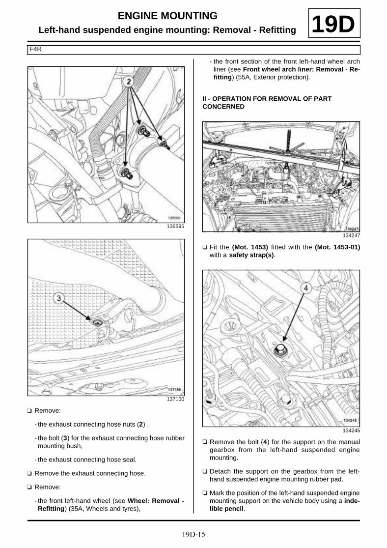
19D-15
ENGINE MOUNTINGLeft-hand suspended engine mounting: Removal - Refitting
F4R
19D
a Remove:
- the exhaust connecting hose nuts (2) ,
- the bolt (3) for the exhaust connecting hose rubbermounting bush,
- the exhaust connecting hose seal.
a Remove the exhaust connecting hose.
a Remove:
- the front left-hand wheel (see Wheel: Removal -Refitting) (35A, Wheels and tyres),
- the front section of the front left-hand wheel archliner (see Front wheel arch liner: Removal - Re-fitting) (55A, Exterior protection).
II - OPERATION FOR REMOVAL OF PART CONCERNED
a Fit the (Mot. 1453) fitted with the (Mot. 1453-01)with a safety strap(s).
a Remove the bolt (4) for the support on the manualgearbox from the left-hand suspended enginemounting.
a Detach the support on the gearbox from the left-hand suspended engine mounting rubber pad.
a Mark the position of the left-hand suspended enginemounting support on the vehicle body using a inde-lible pencil.
136595
137150
134247
134245
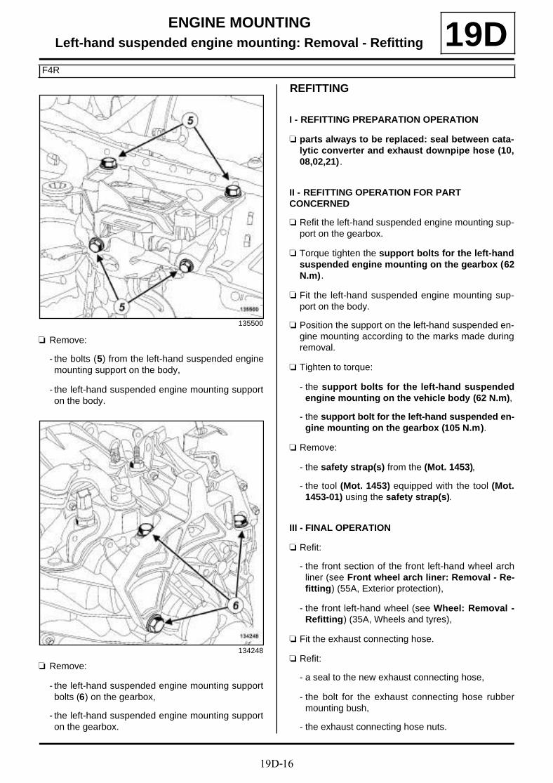
19D-16
ENGINE MOUNTINGLeft-hand suspended engine mounting: Removal - Refitting
F4R
19D
a Remove:
- the bolts (5) from the left-hand suspended enginemounting support on the body,
- the left-hand suspended engine mounting supporton the body.
a Remove:
- the left-hand suspended engine mounting supportbolts (6) on the gearbox,
- the left-hand suspended engine mounting supporton the gearbox.
REFITTING
I - REFITTING PREPARATION OPERATION
a parts always to be replaced: seal between cata-lytic converter and exhaust downpipe hose (10,08,02,21).
II - REFITTING OPERATION FOR PART CONCERNED
a Refit the left-hand suspended engine mounting sup-port on the gearbox.
a Torque tighten the support bolts for the left-handsuspended engine mounting on the gearbox (62N.m).
a Fit the left-hand suspended engine mounting sup-port on the body.
a Position the support on the left-hand suspended en-gine mounting according to the marks made duringremoval.
a Tighten to torque:
- the support bolts for the left-hand suspendedengine mounting on the vehicle body (62 N.m),
- the support bolt for the left-hand suspended en-gine mounting on the gearbox (105 N.m).
a Remove:
- the safety strap(s) from the (Mot. 1453),
- the tool (Mot. 1453) equipped with the tool (Mot.1453-01) using the safety strap(s).
III - FINAL OPERATION
a Refit:
- the front section of the front left-hand wheel archliner (see Front wheel arch liner: Removal - Re-fitting) (55A, Exterior protection),
- the front left-hand wheel (see Wheel: Removal -Refitting) (35A, Wheels and tyres),
a Fit the exhaust connecting hose.
a Refit:
- a seal to the new exhaust connecting hose,
- the bolt for the exhaust connecting hose rubbermounting bush,
- the exhaust connecting hose nuts.
135500
134248

19D-17
ENGINE MOUNTINGLeft-hand suspended engine mounting: Removal - Refitting
F4R
19Da Refit:
- the lower engine tie-bar (see 19D, Engine moun-ting, Lower engine tie-bar: Removal - Refitting,page 19D-33) ,
- the engine undertray.
a Clip on the battery wiring channel.
a Refit:
- the scoop under the scuttle panel grille (see Scoopunder scuttle panel grille: Removal - Refitting)(56A, Exterior equipment),
- the scuttle panel grille (see Scuttle panel grille:Removal - Refitting) (56A, Exterior equipment),
- the windscreen wiper arms (see Windscreen wi-per arm: Removal - Refitting) (85A, Wiping -Washing),
- the air filter unit (see 12A, Fuel mixture, Air filterunit: Removal - Refitting, page 12A-4) ,
- the battery tray (see Battery tray: Removal - Re-fitting) (80A, Battery),
- the battery (see Battery : Removal - Refitting)(80A, Battery),
- the engine cover.
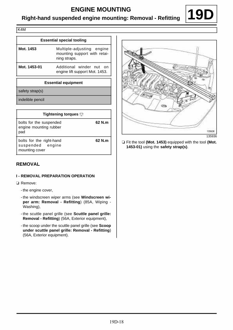
19D-18
ENGINE MOUNTINGRight-hand suspended engine mounting: Removal - Refitting
K4M
19D
REMOVAL
I - REMOVAL PREPARATION OPERATION
a Remove:
- the engine cover,
- the windscreen wiper arms (see Windscreen wi-per arm: Removal - Refitting) (85A, Wiping -Washing),
- the scuttle panel grille (see Scuttle panel grille:Removal - Refitting) (56A, Exterior equipment),
- the scoop under the scuttle panel grille (see Scoopunder scuttle panel grille: Removal - Refitting)(56A, Exterior equipment).
a Fit the tool (Mot. 1453) equipped with the tool (Mot.1453-01) using the safety strap(s).
Essential special tooling
Mot. 1453 Multiple-adjusting enginemounting support with retai-ning straps.
Mot. 1453-01 Additional winder nut onengine lift support Mot. 1453.
Essential equipment
safety strap(s)
indelible pencil
Tightening torquesm
bolts for the suspendedengine mounting rubberpad
62 N.m
bolts for the right-handsuspended enginemounting cover
62 N.m135936
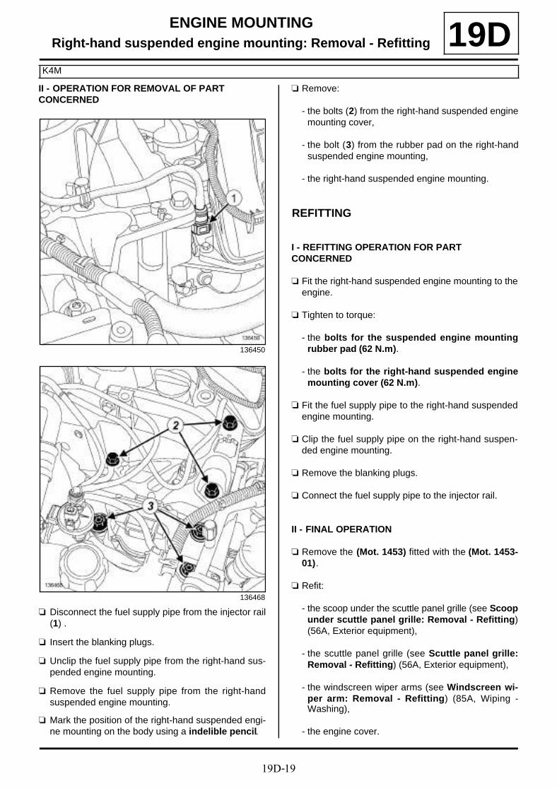
19D-19
ENGINE MOUNTINGRight-hand suspended engine mounting: Removal - Refitting
K4M
19DII - OPERATION FOR REMOVAL OF PART CONCERNED
a Disconnect the fuel supply pipe from the injector rail(1) .
a Insert the blanking plugs.
a Unclip the fuel supply pipe from the right-hand sus-pended engine mounting.
a Remove the fuel supply pipe from the right-handsuspended engine mounting.
a Mark the position of the right-hand suspended engi-ne mounting on the body using a indelible pencil.
a Remove:
- the bolts (2) from the right-hand suspended enginemounting cover,
- the bolt (3) from the rubber pad on the right-handsuspended engine mounting,
- the right-hand suspended engine mounting.
REFITTING
I - REFITTING OPERATION FOR PART CONCERNED
a Fit the right-hand suspended engine mounting to theengine.
a Tighten to torque:
- the bolts for the suspended engine mountingrubber pad (62 N.m).
- the bolts for the right-hand suspended enginemounting cover (62 N.m).
a Fit the fuel supply pipe to the right-hand suspendedengine mounting.
a Clip the fuel supply pipe on the right-hand suspen-ded engine mounting.
a Remove the blanking plugs.
a Connect the fuel supply pipe to the injector rail.
II - FINAL OPERATION
a Remove the (Mot. 1453) fitted with the (Mot. 1453-01).
a Refit:
- the scoop under the scuttle panel grille (see Scoopunder scuttle panel grille: Removal - Refitting)(56A, Exterior equipment),
- the scuttle panel grille (see Scuttle panel grille:Removal - Refitting) (56A, Exterior equipment),
- the windscreen wiper arms (see Windscreen wi-per arm: Removal - Refitting) (85A, Wiping -Washing),
- the engine cover.
136450
136468
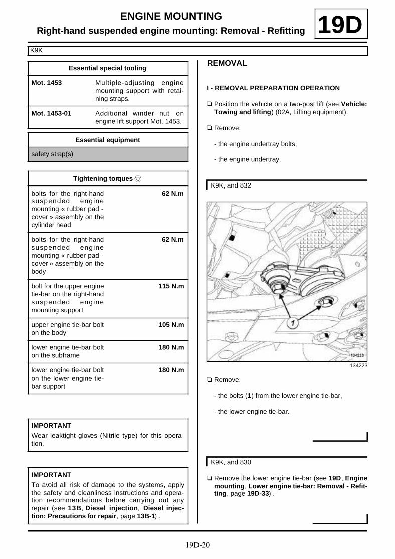
19D-20
ENGINE MOUNTINGRight-hand suspended engine mounting: Removal - Refitting
K9K
19DREMOVAL
I - REMOVAL PREPARATION OPERATION
a Position the vehicle on a two-post lift (see Vehicle:Towing and lifting) (02A, Lifting equipment).
a Remove:
- the engine undertray bolts,
- the engine undertray.
a Remove:
- the bolts (1) from the lower engine tie-bar,
- the lower engine tie-bar.
a Remove the lower engine tie-bar (see 19D, Enginemounting, Lower engine tie-bar: Removal - Refit-ting, page 19D-33) .
Essential special tooling
Mot. 1453 Multiple-adjusting enginemounting support with retai-ning straps.
Mot. 1453-01 Additional winder nut onengine lift support Mot. 1453.
Essential equipment
safety strap(s)
Tightening torquesm
bolts for the right-handsuspended enginemounting « rubber pad -cover » assembly on thecylinder head
62 N.m
bolts for the right-handsuspended enginemounting « rubber pad -cover » assembly on thebody
62 N.m
bolt for the upper enginetie-bar on the right-handsuspended enginemounting support
115 N.m
upper engine tie-bar bolton the body
105 N.m
lower engine tie-bar bolton the subframe
180 N.m
lower engine tie-bar bolton the lower engine tie-bar support
180 N.m
IMPORTANT
Wear leaktight gloves (Nitrile type) for this opera-tion.
IMPORTANT
To avoid all risk of damage to the systems, applythe safety and cleanliness instructions and opera-tion recommendations before carrying out anyrepair (see 13B, Diesel injection, Diesel injec-tion: Precautions for repair, page 13B-1) .
K9K, and 832
134223
K9K, and 830

19D-21
ENGINE MOUNTINGRight-hand suspended engine mounting: Removal - Refitting
K9K
19D
a Disconnect the diesel fuel return pipe from the fuelreturn rail at (2) .
a Fit suitable blanking plugs on:
- the opening of the fuel return rail,
- the diesel return pipe opening.
a Disconnect the diesel fuel return pipe from the highpressure pump union at (2) .
a Fit blanking plugs on:
- the opening of the high pressure pump union,
- the diesel return pipe opening.
a Disconnect the fuel supply pipe (3) from the manualpriming pump.
a Fit suitable blanking plugs on:
- the fuel supply pipe opening,
- the opening of the manual priming pump.
a Unclip the fuel pipes from the right-hand suspendedengine mounting « rubber pad - cover » assembly at(4) .
a Move the fuel pipesto one side.
a Remove:
- the windscreen wiper arms (see Windscreen wi-per arm: Removal - Refitting) (85A, Wiping -Washing),
- the scuttle panel grille (see Scuttle panel grille:Removal - Refitting) (56A, Exterior equipment).
- the scoop under the scuttle panel grille (see Scoopunder scuttle panel grille: Removal - Refitting)(56A, Exterior equipment).
K9K, and 832
134494
K9K, and 830
135412
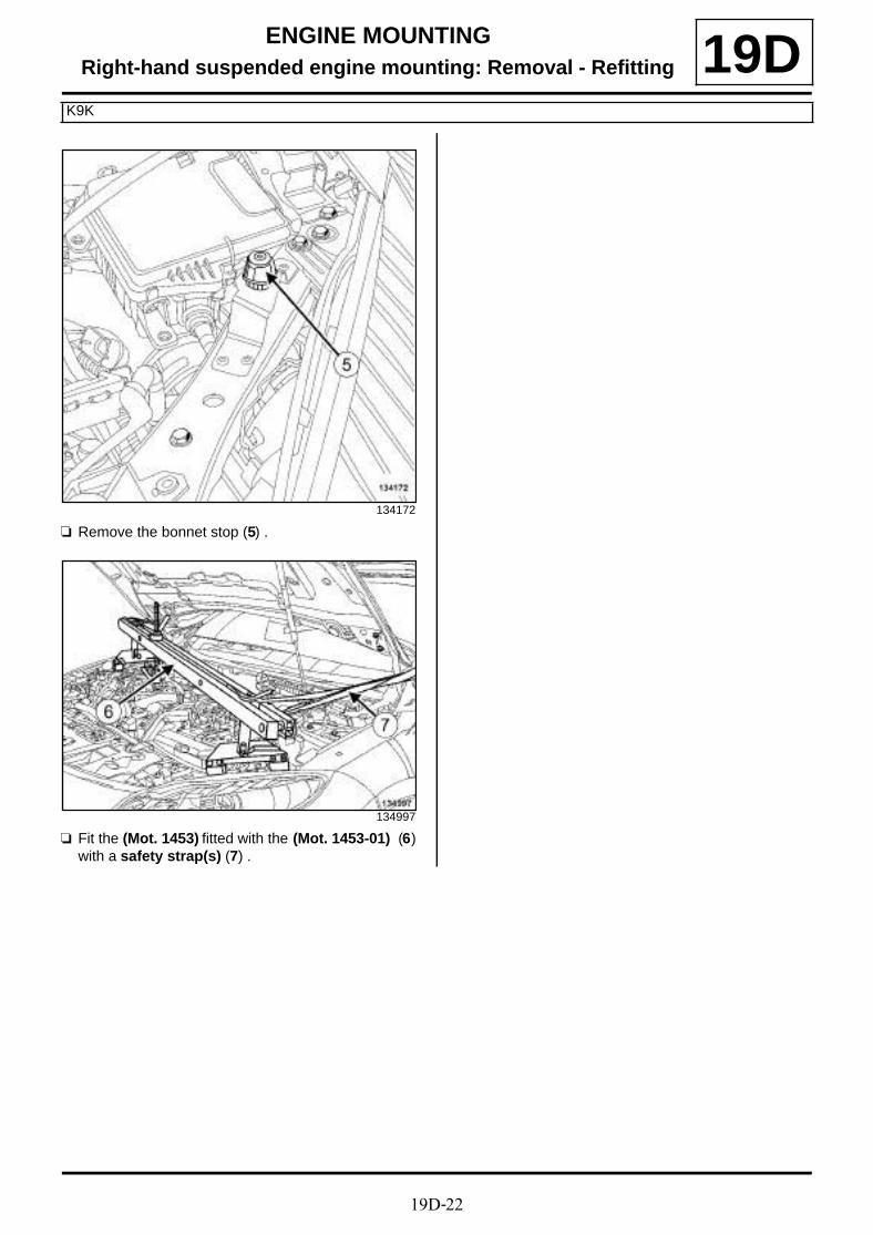
19D-22
ENGINE MOUNTINGRight-hand suspended engine mounting: Removal - Refitting
K9K
19D
a Remove the bonnet stop (5) .
a Fit the (Mot. 1453) fitted with the (Mot. 1453-01) (6)with a safety strap(s) (7) .
134172
134997

19D-23
ENGINE MOUNTINGRight-hand suspended engine mounting: Removal - Refitting
K9K
19DII - OPERATION FOR REMOVAL OF PART CONCERNED
a Remove:
- the upper engine tie-bar bolts (8) ,
- the upper engine tie-bar.
a Remove the bolts (9) for the right-hand suspendedengine mounting « rubber pad - cover » assemblyfrom the body.
a Remove the bolts (9) for the right-hand suspendedengine mounting « rubber pad - cover » assemblyfrom the body.
a Raise the engine slightly using the tool (Mot. 1453)equipped with the tool (Mot. 1453-01) until the right-hand suspended engine mounting « rubber pad -cover » assembly detaches from the body.
K9K, and 832
134221
134495
K9K, and 830
135411

19D-24
ENGINE MOUNTINGRight-hand suspended engine mounting: Removal - Refitting
K9K
19D
a Remove:
- the bolts (10) for the right-hand suspended enginemounting « rubber pad - cover » assembly from thecylinder head,
- the right-hand suspended engine mounting « cover- rubber pad » assembly.
a Remove:
- the bolts (10) for the right-hand suspended enginemounting « rubber pad - cover » assembly from thecylinder head,
- the right-hand suspended engine mounting « cover- rubber pad » assembly.
REFITTING
I - REFITTING OPERATION FOR PART CONCERNED
a Refit the bolts for the right-hand suspended enginemounting « rubber pad - cover » assembly to the cy-linder head.
a Lower the engine using the tool (Mot. 1453) fittedwith the tool (Mot. 1453-01) until the right-hand sus-pended engine mounting « rubber pad - cover » as-sembly touches the body.
a Refit the bolts for the right-hand suspended enginemounting « rubber pad - cover » assembly to the bo-dy.
a Tighten to torque:
- the bolts for the right-hand suspended enginemounting « rubber pad - cover » assembly onthe cylinder head (62 N.m),
K9K, and 832
134495
K9K, and 830
135411

19D-25
ENGINE MOUNTINGRight-hand suspended engine mounting: Removal - Refitting
K9K
19D- the bolts for the right-hand suspended enginemounting « rubber pad - cover » assembly onthe body (62 N.m).
a Refit the upper engine tie-bar.
a Tighten to torque:
- the bolt for the upper engine tie-bar on the ri-ght-hand suspended engine mounting support(115 N.m),
- the upper engine tie-bar bolt on the body (105N.m).
II - FINAL OPERATION
a Remove the safety strap(s) from the tool (Mot.1453).
a Remove the (Mot. 1453) fitted with the (Mot. 1453-01).
a Refit:
- the bonnet stop,
- the scoop under the scuttle panel grille (see Scoopunder scuttle panel grille: Removal - Refitting)(56A, Exterior equipment),
- the scuttle panel grille (see Scuttle panel grille:Removal - Refitting) (56A, Exterior equipment),
- the windscreen wiper arms (see Windscreen wi-per arm: Removal - Refitting) (85A, Wiping -Washing).
a Position the fuel pipes.
a Clip the fuel pipes onto the « rubber pad - cover »assembly of the right-hand suspended enginemounting.
a Remove the blanking plugs from:
- the opening of the manual priming pump,
- the opening of the fuel supply pipe.
a Connect the fuel supply pipe union to the union ofthe manual priming pump.
a Remove the blanking plugs from:
- the diesel return pipe opening,
- the opening of the fuel return rail.
a Connect the diesel fuel return pipe to the fuel returnrail.
a Remove the blanking plugs from:
- the diesel return pipe opening,
- the opening of the high pressure pump union.
a Connect the diesel fuel return pipe to the high pres-sure pump union.
a Refit the lower engine tie-bar.
a Tighten to torque:
- the lower engine tie-bar bolt on the subframe(180 N.m),
- the lower engine tie-bar bolt on the lower engi-ne tie-bar support (180 N.m).
a Refit the lower engine tie-bar (see 19D, Enginemounting, Lower engine tie-bar: Removal - Refit-ting, page 19D-33) .
a Refit the engine undertray.
K9K, and 832
K9K, and 832
K9K, and 830
K9K, and 832
K9K, and 830

19D-26
ENGINE MOUNTINGRight-hand suspended engine mounting: Removal - Refitting
F4R
19D
REMOVAL
I - REMOVAL PREPARATION OPERATION
a Position the vehicle on a two-post lift (see Vehicle:Towing and lifting) (02A, Lifting equipment).
a Remove:
- the engine cover,
- the engine undertray bolts,
- the engine undertray,
- the lower engine tie-bar (see 19D, Engine moun-ting, Lower engine tie-bar: Removal - Refitting,page 19D-33) .
Essential special tooling
Mot. 1453 Multiple-adjusting enginemounting support with retai-ning straps.
Mot. 1453-01 Additional winder nut onengine lift support Mot. 1453.
Essential equipment
safety strap(s)
Tightening torquesm
upper engine tie-barbolts
115 N.m
bolts for the right-handsuspended enginemounting rubber pad
62 N.m
bolts for the right-handsuspended enginemounting cover
62 N.m
WARNING
To prevent impurities from entering the circuit, placeprotective plugs on all fuel circuit componentsexposed to the open air.

19D-27
ENGINE MOUNTINGRight-hand suspended engine mounting: Removal - Refitting
F4R
19D
a Disconnect:
- the petrol vapour rebreathing solenoid valve pipe(1) ,
- the fuel supply pipe (2) on the injector rail,
a Insert the blanking plugs.
a Unclip the pipes from the cover of the right-handsuspended engine mounting at (3) .
a Remove:
- the windscreen wiper arms (see Windscreen wi-per arm: Removal - Refitting) (85A, Wiping -Washing),
- the scuttle panel grille (see Scuttle panel grille:Removal - Refitting) (56A, Exterior equipment),
- the scoop under the scuttle panel grille (see Scoopunder scuttle panel grille: Removal - Refitting)(56A, Exterior equipment).
134645
135779
134644
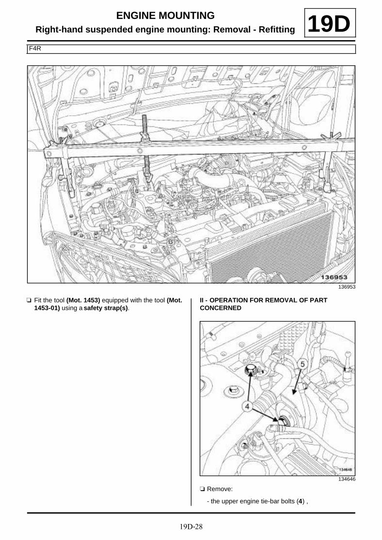
19D-28
ENGINE MOUNTINGRight-hand suspended engine mounting: Removal - Refitting
F4R
19D
a Fit the tool (Mot. 1453) equipped with the tool (Mot.1453-01) using a safety strap(s).
II - OPERATION FOR REMOVAL OF PART CONCERNED
a Remove:
- the upper engine tie-bar bolts (4) ,
136953
134646

19D-29
ENGINE MOUNTINGRight-hand suspended engine mounting: Removal - Refitting
F4R
19D- the upper engine tie-bar (5) .
a Remove:
- the bolts (6) from the right-hand suspended enginemounting rubber pad on the vehicle body,
- the bolts (7) from the right-hand suspended enginemounting cover,
- the right-hand suspended engine mounting « cover- rubber pad » assembly.
REFITTING
I - REFITTING OPERATION FOR PART CONCERNED
a Refit the right-hand suspended engine mounting« cover - rubber pad » assembly.
a Fit without tightening:
- the bolts for the right-hand suspended enginemounting cover,
- the bolts for the right-hand suspended enginemounting rubber pad.
a Refit the upper engine tie-bar.
a Tighten to torque:
- the upper engine tie-bar bolts (115 N.m),
- the bolts for the right-hand suspended enginemounting rubber pad (62 N.m),
- the bolts for the right-hand suspended enginemounting cover (62 N.m).
II - FINAL OPERATION
a Remove the tool (Mot. 1453) equipped with the tool(Mot. 1453-01) using the safety strap(s).
a Refit:
- the scoop under the scuttle panel grille (see Scoopunder scuttle panel grille: Removal - Refitting)(56A, Exterior equipment),
- the scuttle panel grille (see Scuttle panel grille:Removal - Refitting) (56A, Exterior equipment),
- the windscreen wiper arms (see Windscreen wi-per arm: Removal - Refitting) (85A, Wiping -Washing),
a Clip the pipes onto the cover of the front right-handsuspended engine mounting.
a Remove the blanking plugs.
a Connect:
- the fuel supply pipe to the injector rail,
- the pipe to the fuel vapour rebreathing solenoid val-ve.
a Refit:
- the lower engine tie-bar (see 19D, Engine moun-ting, Lower engine tie-bar: Removal - Refitting,page 19D-33) ,
- the engine undertray,
- the engine cover.
138080

19D-30
ENGINE MOUNTINGRight-hand suspended engine mounting: Removal - Refitting
F9Q
19D
REMOVAL
I - REMOVAL PREPARATION OPERATION
a Position the vehicle on a two-post lift (see Vehicle:Towing and lifting) (02A, Lifting equipment).
a Remove:
- the engine cover,
- the engine undertray bolts,
- the engine undertray.
- the lower engine tie-bar (see 19D, Engine moun-ting, Lower engine tie-bar: Removal - Refitting,page 19D-33) ,
- the windscreen wiper arms (see Windscreen wi-per arm: Removal - Refitting) (85A, Wiping -Washing),
- the scuttle panel grille (see Scuttle panel grille:Removal - Refitting) (56A, Exterior equipment),
- the scoop under the scuttle panel grille (see Scoopunder scuttle panel grille: Removal - Refitting)(56A, Exterior equipment).
a Remove the front left-hand bonnet stop (1) .
a Position the (Mot. 1453) and (Mot. 1453-01).
Essential special tooling
Mot. 1453 Multiple-adjusting enginemounting support with retai-ning straps.
Mot. 1453-01 Additional winder nut onengine lift support Mot. 1453.
Essential equipment
indelible pencil
Tightening torquesm
right-hand suspendedengine mounting bolts
62 N.m
engine tie-bar bolt onthe body
110 N.m
engine tie-bar bolt onthe engine
115 N.m134172
134173
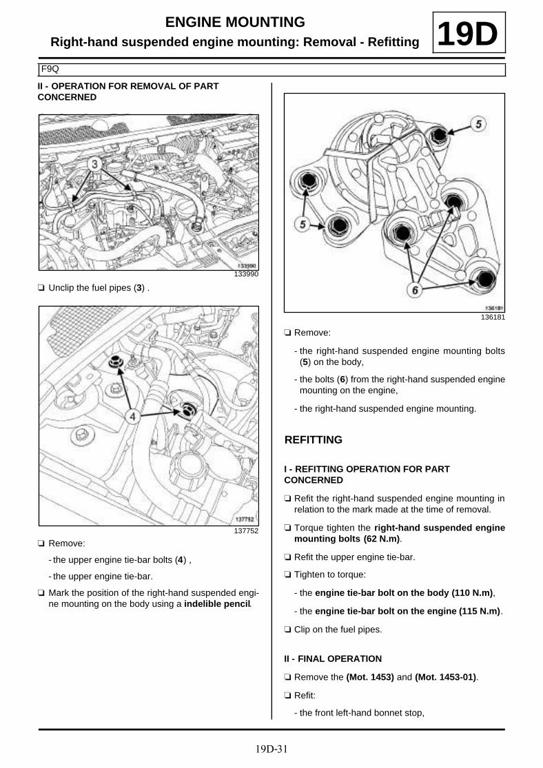
19D-31
ENGINE MOUNTINGRight-hand suspended engine mounting: Removal - Refitting
F9Q
19DII - OPERATION FOR REMOVAL OF PART CONCERNED
a Unclip the fuel pipes (3) .
a Remove:
- the upper engine tie-bar bolts (4) ,
- the upper engine tie-bar.
a Mark the position of the right-hand suspended engi-ne mounting on the body using a indelible pencil.
a Remove:
- the right-hand suspended engine mounting bolts(5) on the body,
- the bolts (6) from the right-hand suspended enginemounting on the engine,
- the right-hand suspended engine mounting.
REFITTING
I - REFITTING OPERATION FOR PART CONCERNED
a Refit the right-hand suspended engine mounting inrelation to the mark made at the time of removal.
a Torque tighten the right-hand suspended enginemounting bolts (62 N.m).
a Refit the upper engine tie-bar.
a Tighten to torque:
- the engine tie-bar bolt on the body (110 N.m),
- the engine tie-bar bolt on the engine (115 N.m).
a Clip on the fuel pipes.
II - FINAL OPERATION
a Remove the (Mot. 1453) and (Mot. 1453-01).
a Refit:
- the front left-hand bonnet stop,
133990
137752
136181
19D-32
ENGINE MOUNTINGRight-hand suspended engine mounting: Removal - Refitting
F9Q
19D- the scoop under the scuttle panel grille (see Scoopunder scuttle panel grille: Removal - Refitting)(56A, Exterior equipment),
- the scuttle panel grille (see Scuttle panel grille:Removal - Refitting) (56A, Exterior equipment),
- the windscreen wiper arms (see Windscreen wi-per arm: Removal - Refitting) (85A, Wiping -Washing),
- the lower engine tie-bar (see 19D, Engine moun-ting, Lower engine tie-bar: Removal - Refitting,page 19D-33) ,
- the engine undertray.
- the engine cover.
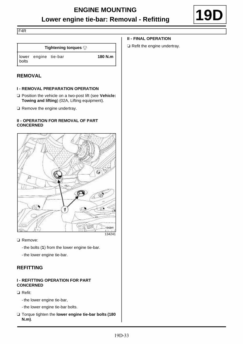
19D-33
ENGINE MOUNTINGLower engine tie-bar: Removal - Refitting
F4R
19D
REMOVAL
I - REMOVAL PREPARATION OPERATION
a Position the vehicle on a two-post lift (see Vehicle:Towing and lifting) (02A, Lifting equipment).
a Remove the engine undertray.
II - OPERATION FOR REMOVAL OF PART CONCERNED
a Remove:
- the bolts (1) from the lower engine tie-bar.
- the lower engine tie-bar.
REFITTING
I - REFITTING OPERATION FOR PART CONCERNED
a Refit:
- the lower engine tie-bar,
- the lower engine tie-bar bolts.
a Torque tighten the lower engine tie-bar bolts (180N.m).
II - FINAL OPERATION
a Refit the engine undertray.Tightening torquesm
lower engine tie-barbolts
180 N.m
134241
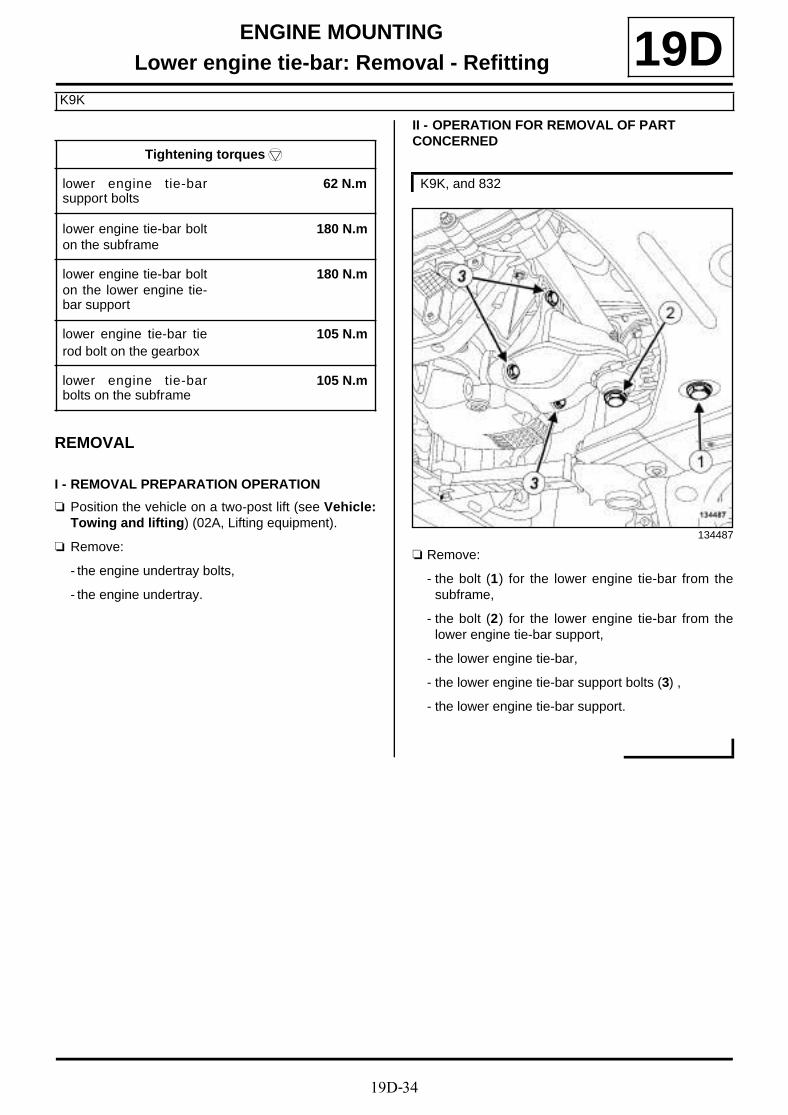
19D-34
ENGINE MOUNTINGLower engine tie-bar: Removal - Refitting
K9K
19D
REMOVAL
I - REMOVAL PREPARATION OPERATION
a Position the vehicle on a two-post lift (see Vehicle:Towing and lifting) (02A, Lifting equipment).
a Remove:
- the engine undertray bolts,
- the engine undertray.
II - OPERATION FOR REMOVAL OF PART CONCERNED
a Remove:
- the bolt (1) for the lower engine tie-bar from thesubframe,
- the bolt (2) for the lower engine tie-bar from thelower engine tie-bar support,
- the lower engine tie-bar,
- the lower engine tie-bar support bolts (3) ,
- the lower engine tie-bar support.
Tightening torquesm
lower engine tie-barsupport bolts
62 N.m
lower engine tie-bar bolton the subframe
180 N.m
lower engine tie-bar bolton the lower engine tie-bar support
180 N.m
lower engine tie-bar tierod bolt on the gearbox
105 N.m
lower engine tie-barbolts on the subframe
105 N.m
K9K, and 832
134487

19D-35
ENGINE MOUNTINGLower engine tie-bar: Removal - Refitting
K9K
19D
a Undo the bolt (4) for the lower engine tie-bar tie rodon the gearbox.
a Remove:
- the lower engine tie-bar tie rod bolt (5) ,
- the lower engine tie-bar tie rod (6) ,
- the bolt (7) for the lower engine tie-bar from thesubframe,
- the lower engine tie-bar.
REFITTING
I - REFITTING OPERATION FOR PART CONCERNED
a Refit the lower engine tie-bar support.
a Torque tighten the lower engine tie-bar supportbolts (62 N.m).
a Refit the lower engine tie-bar on the subframe.
a Tighten to torque:
- the lower engine tie-bar bolt on the subframe(180 N.m),
- the lower engine tie-bar bolt on the lower engi-ne tie-bar support (180 N.m).
a Refit without tightening:
- the lower engine tie-bar,
- the lower engine tie-bar tie rod.
a Tighten to torque:
- the lower engine tie-bar tie rod bolt on the gear-box (105 N.m),
- the lower engine tie-bar bolts on the subframe(105 N.m).
II - FINAL OPERATION
a Refit the engine undertray.
K9K, and 830 or 834
135847
K9K, and 832
K9K, and 830 or 834

19D-36
ENGINE MOUNTINGLower engine tie-bar: Removal - Refitting
F9Q
19D
REMOVAL
I - REMOVAL PREPARATION OPERATION
a Position the vehicle on a two-post lift (see Vehicle:Towing and lifting) (02A, Lifting equipment).
a Remove:
- the engine undertray bolts,
- the engine undertray.
II - OPERATION FOR REMOVAL OF PART CONCERNED
a Remove:
- the bolt (1) from the lower engine tie-bar on thesub-frame,
- the bolt (2) mounting the lower engine tie-bar on itssupport,
- the lower engine tie-bar.
a Remove:
- the bolts (3) from the lower engine tie-bar support,
- the lower engine tie-bar support.
REFITTING
I - REFITTING OPERATION FOR PART CONCERNED
a Refit:
- the lower engine tie-bar support,
- the lower engine tie-bar.
a Tighten to torque:
- the engine tie-bar bolt on its support (180 N.m),
- the engine tie-bar bolt on the subframe (180N.m).
II - FINAL OPERATION
a Refit the engine undertray.
Tightening torquesm
engine tie-bar bolt on itssupport
180 N.m
engine tie-bar bolt onthe subframe
180 N.m
134629
135540

19D-37
ENGINE MOUNTINGLower engine tie-bar: Removal - Refitting
K4M
19D
REMOVAL
I - REMOVAL PREPARATION OPERATION
a Position the vehicle on a two-post lift (see Vehicle:Towing and lifting) (02A, Lifting equipment).
a Remove:
- the engine undertray bolts,
- the engine undertray.
II - OPERATION FOR REMOVAL OF PART CONCERNED
a Remove:
- the bolt (1) of the lower engine tie-bar from the frontaxle subframe,
- the gearbox lower engine tie-bar bolt (2) ,
- the lower engine tie-bar.
a Remove:
- the bolt (3) of the lower engine tie-bar from the frontaxle subframe,
- the gearbox lower engine tie-bar bolt (4) ,
- the bolt (5) from the gearbox lower engine tie-barreinforcement,
- the lower engine tie-bar with its reinforcement.
REFITTING
I - REFITTING OPERATION FOR PART CONCERNED
a Refit the lower engine tie-bar.
Tightening torquesm
lower engine tie-bar bolton the gearbox
105 N.m
lower engine tie-bar bolton the front axle sub-frame
105 N.m
reinforcement bolt secu-ring the lower enginetie-bar to the gearbox
105 N.m
K4M, and 848
136476
K4M, and 858 or 866
136493
K4M, and 848

19D-38
ENGINE MOUNTINGLower engine tie-bar: Removal - Refitting
K4M
19D
a Refit the lower engine tie-bar with its reinforcement.
a Tighten to torque:
- the lower engine tie-bar bolt on the gearbox(105 N.m),
- the lower engine tie-bar bolt on the front axlesubframe (105 N.m).
a Torque tighten the reinforcement bolt securingthe lower engine tie-bar to the gearbox (105N.m).
II - FINAL OPERATION
a Refit the engine undertray.
K4M, and 858 or 866
K4M, and 858 or 866