1 green-cap (e d l c - cn-cfe.com · mt bl bj kj mp mj bk bm mw pf cs rb wt va vb np ns ne rn vm vl...
TRANSCRIPT
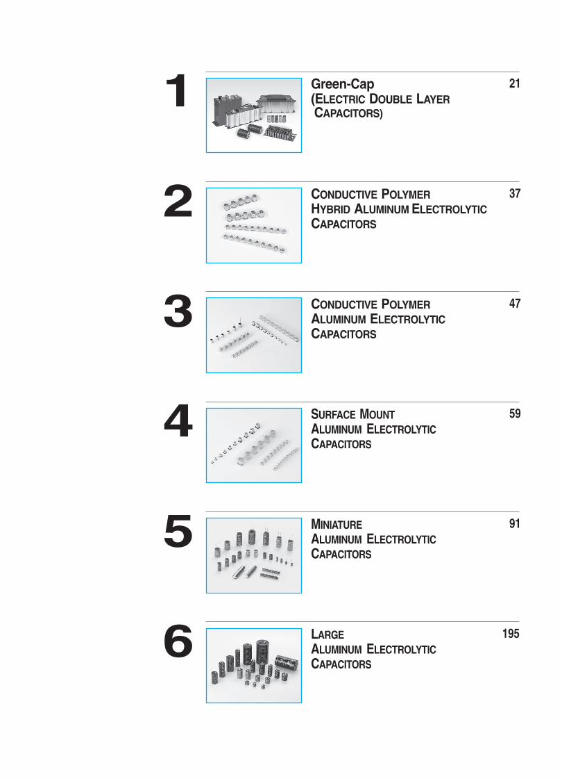
Green-Cap(ELECTRIC DOUBLE LAYER CAPACITORS)
211
CONDUCTIVE POLYMER HYBRID ALUMINUM ELECTROLYTICCAPACITORS
372
CONDUCTIVE POLYMERALUMINUM ELECTROLYTICCAPACITORS
473
SURFACE MOUNTALUMINUM ELECTROLYTICCAPACITORS
594
MINIATURE ALUMINUM ELECTROLYTICCAPACITORS
915
LARGE ALUMINUM ELECTROLYTIC CAPACITORS
1956

4
SERIES CHART
ALUMINUM ELECTROLYTIC CAPACITORS
Green-Cap(ELECTRIC DOUBLE LAYER CAPACITORS)
Conductive polymer hybrid aluminum electrolytic capacitors
Conductive polymer aluminum electrolytic capacitors
CHIP TYPES
MINIATURE RADIAL LEAD TYPES

5
SERIES CHART
MINIATURE RADIAL LEAD TYPES
LARGE TYPES
ALUMINUM ELECTROLYTIC CAPACITORS

6
CONTENTS
Green-Cap(Electric Double Layer Capacitors)
DM
DH
DV
DT
DB
DK
DA
DS
DJ
Green-Cap Module
Axial type, high power density
Axial type, high power density, high voltage
Axial type, high power density, high temp.
Snap-in type, standard series
Snap-in type, high temp.
Snap-in type, high voltage
Lead type, OEM products
Lead type, OEM products, high temp.
Series chart
Application guidelines
Part number system, Lead forming, Cutting, Taping and Packaging
-40
-40
-40
-25(-40)
-40
-40
-30(-40)
-40
~
~
~
~
~
~
~
~
65
65
85
70(65)
85
65
70(65)
85
2.7
2.85
2.5
2.5, 2.7
2.5
3
2.5, 2.7, 3.0
2.5
1200
1200
1200
100
100
100
3
3
~
~
~
~
~
~
~
~
3000
3000
3000
400
400
400
60
60
1500
1500
1500
1500
1500
1500
1000
1000
4
24
26
28
29
30
31
32
33
34
35
36
OperatingTemperature
Range(°C)
VoltageRange(VDC)
CapacitanceRange
(F)
Load LifeTime
(hours)Page
New seriesUpgrade series
Green-Cap modules are supplied on custom-made basis.
Surface Mount Aluminum Electrolytic Capacitors
Series
SC Standard
Standard, wide temp.
Chip type, wide temp. high CV
Chip type, high ripple
Chip type, long life
Chip type, long life
Chip type, long life, 5.5mmL height
Chip type, long life, for ECU
5.5mmL chip type, low Impedance
Chip type, low Impedance, high CV
Chip type, extremely low Impedance
Chip type, extremely low Impedance, high ripple
Chip type, extremely low Impedance, long life
Chip type, high temp. for 125 C use
Chip type, high temp. low ESR. for 125 C use
Chip type, high temp. for 130 C use, long life
Chip type, high temp. for 135 C use, low ESR
Chip type, high reliability
5.5mmL chip, non-polarized
5.5mmL chip type, wide temp. non-polarized
-40 ~ 85
-55 ~ 105
-55(-40) ~ 105
-55(-40) ~ 105
-25 ~ 105
-55(-40) ~ 105
-40 ~ 105
-40 ~ 105
-55 ~ 105
-55 ~ 105
-55 ~ 105
-55 ~ 105
-55 ~ 105
-40 ~ 125
-40 ~ 125
-40 ~ 130
-40 ~ 135
-40 ~ 150
-40 ~ 85
-40 ~ 105
4 ~ 450
6.3 ~ 50
4 ~ 450
6.3 ~ 450
6.3 ~ 450
6.3 ~ 50
4 ~ 50
10 ~ 50
6.3 ~ 35
6.3 ~ 100
6.3 ~ 50
6.3 ~ 35
6.3 ~ 100
10 ~ 400
10 ~ 400
10 ~ 50
10 ~ 50
10 ~ 50
6.3 ~ 50
6.3 ~ 50
1 ~ 2200
1 ~ 1000
3.3 ~ 2200
3.3 ~ 2200
3.3 ~ 2200
10 ~ 1000
1 ~ 100
33 ~ 470
1.0 ~ 100
10 ~ 1500
10 ~ 1500
33 ~ 1500
10 ~ 1000
3.3 ~ 1000
1 ~ 470
22 ~ 1000
47 ~ 470
33 ~ 1000
1 ~ 47
1 ~ 47
2000
1000
2000
2000
3000
5000
5000
10000
1000
2000
2000
2000
3000 ~ 5000
2000
1000 ~ 5000
2000 ~ 5000
2000
1000
2000
1000
4
11
60
61
62
64
65
67
69
71
72
73
74
75
77
79
81
83
84
86
87
88
89
90
Series chart
Application guidelines, General introduction
Part number system
Taping specification & Packaging quantity
NC
RC
UC
ZC
JC
CB
JM
JH
CK
CD
CN
CA
JL
CF
UR
CW
KC
CZ
SM
D
FeaturesOperating
TemperatureRange(°C) G
ener
al
Min
iatu
re
Long
Life
Solve
nt Pro
of VoltageRange(VDC)
CapacitanceRange
( F)
Load LifeTime
(hours)Page
CM
Conductive Polvmer Hybrid Aluminum Electrolytic Capacitors
Series
YC Chip type, HYBRID long life
Chip type, HYBRID long high temp.
-55 ~ 105
-55 ~ 125
16 ~ 80
16 ~ 80
10 ~ 470
10 ~ 470
5000
4000
4
39
41
43
45
Series chart
Application guidelines, General introduction
Part number system
YHSM
D
FeaturesOperating
TemperatureRange(°C)
VoltageRange(VDC)
CapacitanceRange
( F)
Load LifeTime
(hours)Page
Series Features
Conductive Polvmer Aluminum Electrolytic Capacitors
Series
FA Chip type, with conductive polymer (Hi-CAP)
Lead type, with conductive polymer (Hi-CAP)
-55 ~ 105
-55 ~ 105
2.5 ~ 16
2.5 ~ 16
39 ~ 2700
100 ~ 3500
2000
2000
4
49
52
55
57
Series chart
Application guidelines, General introduction
Part number system
FB
SMD
LEAD
FeaturesOperating
TemperatureRange(°C)
VoltageRange(VDC)
CapacitanceRange
( F)
Load LifeTime
(hours)Page

7
CONTENTS
Series FeaturesOperating
TemperatureRange(°C) G
ener
al
Min
iatu
re
Long
Life
Solve
nt Pro
of VoltageRange(VDC)
CapacitanceRange
( F)
Load LifeTime
(hours)Page
Miniature Aluminum Electrolytic Capacitors New seriesUpgrade series
SD
SS
SE
RD
RM
RK
RE
ZS
ZL
ZE
ZT
RZ
WL
RP
WF
LK
MK
MQ
MZ
MB
LZ
ML
MH
MN
KN
MD
SJ
SB
LY
LQ
LJ
PJ
BA
RH
RU
BH
MU
MT
BL
BJ
KJ
MP
MJ
BK
BM
MW
PF
CS
RB
WT
VA
VB
NP
NS
NE
RN
VM
VL
Standard
Standard, height 7mmL
Standard, height 5mmL
Standard, wide temp
Wide temp. capacitance wide range, miniature
Wide temp. range, height 7mmL
Wide temp. range, height 5mmL
Height 7mmL, low impedance, high ripple
Height 7mmL, low impedance, high ripple
Height 5mmL, low impedance, high ripple
Height 7mmL, long life
Extremely low impedance, high reliability
Extremely low imp., miniaturized, wide voltage
Extremely low impedance, long life
Extremely low impedance, miniaturized, long life
Extremely low impedance, high ripple
Ultra low impedance, miniaturized, high ripple
Ultra low impedance, miniaturized, high ripple
Ultra low impedance, miniaturized, high ripple
Ultra low impedance, miniaturized
Ultra low impedance, long life
Ultra low impedance, long life
Ultra low impedance, long life
Ultra low impedance, high ripple
Ultra low impedance, high ripple
Ultra low impedance, high ripple
For PSU applications, long life
For PSU applications, high ripple, long life
For LED lighting applications, long life
For LED lighting applications,Ultra low imp., high ripple
For LED lighting applications, wide voltage, high temp. for 130 C use
For LED lighting applications, high temp.
For PSU applications, smaller case size
For PSU applications, high ripple current
For PSU applications, high ripple current
For PSU applications, high ripple current
For Display applications, high ripple current
For Display applications, high reliability
For PSU applications, long life
For PSU applications, extremely long life
For PSU applications, extremely long life, high ripple current
For Display applications, long life
For PSU applications, high ripple, long life
For PSU applications, high temp. for 125 C use
For PSU applications, high temp. for 150 C use
High ripple current
High ripple current, long life
For charger, adapter
High temp. range, for 125 C use, miniaturized
High temp. range, for 125 C use, Long life, low impedance
High temp. range, for 130 C use, low impedance
High temp. range, for 155 C
Standard
Height 7mm
Height 5mm
Wide temp. range
Long life, for reflow coditions
Long life, for reflow coditions
-40(-25) ~ 85
-40 ~ 85
-40 ~ 85
-55(-40,-25)~105
-55(-40) ~ 105
-55 ~ 105
-55 ~ 105
-40 ~ 105
-40 ~ 105
-55 ~ 105
-40 ~ 105
-55 ~ 105
-40(-25) ~ 105
-55 ~ 105
-40 ~ 105
-55(40) ~ 105
-40 ~ 105
-40 ~ 105
-40 ~ 105
-40 ~ 105
-40 ~ 105
-40 ~ 105
-40 ~ 105
-40 ~ 105
-40 ~ 105
-40 ~ 105
-25 ~ 85
-25 ~ 85
-25 ~ 105
-40 ~ 105
-40(-25) ~ 130
-40 ~ 105
-40(-25) ~ 105
-40(-25) ~ 105
-40(-25) ~ 105
-25 ~ 105
-40(-25) ~ 105
-40 ~ 105
-40(-25) ~ 105
-40(-25) ~ 105
-40(-25) ~ 105
-40 ~ 105
-40(-25) ~ 105
-25 ~ 125
-25 ~ 150
-40(-25) ~ 105
-40 ~ 105
-25 ~ 105
-55(-40) ~ 125
-40 ~ 125
-40 ~ 130
-40 ~ 155
-40 ~ 85
-40 ~ 85
-40 ~ 85
-40 ~ 105
-40 ~ 105
-40 ~ 105
1.0 ~ 22000
1.0 ~ 220
1.0 ~ 330
2.2 ~ 22000
1.0 ~ 22000
1.0 ~ 68
1.0 ~ 220
2.2 ~ 330
2.2 ~ 330
1.0 ~ 100
2.2 ~ 330
1.0 ~ 15000
1.0 ~ 15000
1.0 ~ 15000
1.0 ~ 15000
1.0 ~ 6800
1.0 ~ 15000
4.7 ~ 2200
1.0 ~ 15000
1.0 ~ 8200
10 ~ 8200
10 ~ 10000
10 ~ 10000
100 ~ 3300
33 ~ 3300
470 ~ 3300
47 ~ 150
47 ~ 150
1 ~ 330
8.2 ~ 8200
1.0 ~ 4700
1.0 ~ 33
1.0 ~ 220
1.0 ~ 220
3.3 ~ 150
2.2 ~ 100
10 ~ 470
10 ~ 470
4.7 ~ 150
4.7 ~ 470
1 ~ 470
10 ~ 470
3.3 ~ 470
2.2 ~ 47
2.2 ~ 47
4.7 ~ 470
10 ~ 150
2.2 ~68
0.47 ~ 15000
10 ~ 3300
220 ~ 4700
1.0 ~ 4700
1.0 ~ 10000
1.0 ~ 47
1.0 ~ 47
1.0 ~ 6800
15 ~ 1000
15 ~ 1000
2000
2000
2000
1000 ~ 2000
1000 ~ 2000
1000
1000
2000
3000
2000
5000
2000 ~ 5000
2000 ~ 5000
4000 ~ 10000
5000 ~ 10000
2000 ~ 5000
2000 ~ 5000
2000 ~ 5000
2000 ~ 5000
2000 ~ 5000
6000 ~ 10000
6000 ~ 10000
7000 ~ 12000
3000 ~ 5000
3000 ~ 5000
2000
8000
10000
10000
6000 ~ 10000
1000 ~ 4000
3000
2000
5000
5000
5000
5000
12000
10000
12000
12000
12000 ~ 15000
15000 ~ 20000
2000 ~ 5000
2000
5000
10000
2000
1000 ~ 2000
2000 ~ 5000
2000 ~ 4000
1000
2000
2000
1000
1000
5000
8000
6.3 ~ 500
4 ~ 63
4 ~ 63
6.3 ~ 500
6.3 ~ 450
4 ~ 63
4 ~ 50
6.3 ~ 50
6.3 ~ 50
6.3 ~ 35
6.3 ~ 50
6.3 ~ 63
6.3 ~ 500
6.3 ~ 50
6.3 ~ 100
6.3 ~ 100
6.3 ~ 100
6.3 ~ 50
6.3 ~ 100
6.3 ~ 100
6.3 ~ 50
6.3 ~ 100
6.3 ~ 35
6.3 ~ 50
10 ~ 35
6.3 ~ 16
420 ~ 500
420 ~ 500
10 ~ 50
6.3 ~ 120
10 ~ 400
200 ~ 450
160 ~ 500
160 ~ 500
160 ~ 500
200 ~ 400
160 ~ 500
160 ~ 500
160 ~ 500
160 ~ 500
160 ~ 500
160 ~ 500
160 ~ 500
160 ~ 450
160 ~ 400
25 ~ 500
160 ~ 275
400 ~ 450
6.3 ~ 250
6.3 ~ 100
10 ~ 35
10 ~ 100
6.3 ~ 250
6.3 ~ 63
6.3 ~ 50
6.3 ~ 100
25 ~ 250
25 ~ 250
4~5
11
92
93
97
100
101
102
105
107
108
109
110
111
112
113
115
118
120
122
124
127
129
131
134
136
138
140
142
144
145
146
147
148
150
152
153
154
156
158
159
161
163
165
167
169
171
173
174
175
176
177
178
181
183
185
187
189
190
191
193
193Reflow
Lo
w Im
ped
ance
PS
U, C
har
ger
, Ad
apte
r, L
ED
Spe
cial
App
licat
ions
Non
-pol
ariz
e
Series chart
Application guidelines, General introduction
Part number system
Lead forming, taping & Packaging quantity
Gen
eral
Ty
pe(1
05C
)
Gen
eral
Ty
pe(8
5C
)

8
CONTENTS
Large Aluminum Electrolytic Capacitors
Series FeaturesOperating
TemperatureRange(°C)
VoltageRange(VDC)
Gen
eral
Min
iatu
re
Long
life
Solv
ent P
roof
CapacitanceRange
( F)
Load LifeTime
(hours)Page
Series chart
Part number system
Packaging q'ty(pcs) / box
HC
HJ
HF
HE
JK
HK
HG
KG
HL
JF
HY
JY
HB
LM
GT
GM
CU
GF
GQ
GL
EV
EY
LW,SW
AM
DF
AR,AG
AL
AK
AJ
Scr
ew T
erm
inal
LUG
Ter
mina
lS
nap
-in
Ter
min
alS
pec
ial T
ype
5
196
197
200
203
206
208
211
213
216
217
218
221
223
225
227
229
231
234
236
239
241
243
245
246
248
249
251
253
254
255
256
Standard
Miniaturized
Long life
Wide temp. range, standard
Wide temp. range, high ripple current
Wide temp. range, miniaturized
Wide temp. range, high ripple current
Wide temp. range, high ripple current
Wide temp. range, miniaturized, long life
Wide temp. range, long life, high ripple current
Wide temp. range, long life
Wide temp. range, long life
High temp. range, for 125 C use
For general use
Standard
High ripple current, miniaturized
Wide temp. range, standard
For inverter circuits, long life
For inverter circuits, long life, high ripple, miniaturized
High ripple, long life
For inverter circuits, long life
For inverter circuits, long life
For Welding Machine
For audio equipment
For photo flash
For inverter air-conditioning system
For inverter air-conditioning system, high ripple current
For inverter air-conditioning system, high ripple current
For inverter air-conditioning system, high ripple current,long life
-40(-25)
-40(-25)
-40(-25)
-40(-25)
-40(-25)
-40(-25)
-40(-25)
-40
-40(-25)
-25
-40(-25)
-25
-40
-40(-25)
-40(-25)
-25
-40(-25)
-25
-25
-25
-25
-25
-25
-40
-20
-40(-25)
-40
-40
-40
6.3
10
160
6.3
250
6.3
250
400
10
400
160
400
10
16
16
350
16
350
400
350
400
350
16
400
315, 475
450
450
450
330, 360
~
~
~
~
~
~
~
~
~
~
~
~
~
~
~
~
~
~
~
~
~
~
~
~
~
~
~
~
~
~
~
~
~
~
~
~
~
~
~
~
~
~
~
~
~
~
~
~
~
~
~
~
~
85
85
85
105
105
105
105
105
105
105
105
105
125
85
85
85
105
85
85
85
105
105
85
85
55
85
85
105
105
550
500
450
550
450
500
450
450
500
450
500
450
250
450
500
450
500
600
450
450
500
450
100
450
47
56
56
47
82
68
150
100
47
56
47
47
100
68
180
820
1000
1000
1800
1500
1000
1500
225
470
200
560
560
470
560
~
~
~
~
~
~
~
~
~
~
~
~
~
~
~
~
~
~
~
~
~
~
~
~
~
~
~
~
~
100000
56000
3300
68000
1500
68000
680
470
56000
470
1800
470
15000
150000
680000
10000
470000
12000
12000
12000
6800
12000
2200
33000
1500
1000
820
820
820
2000
3000
5000
2000
2000
3000
3000
3000
5000
5000
7000
10000
1000
2000
2000
2000
2000
5000
5000
20000
2000 ~ 5000
7000
-
2000
-
3000
5000
3000
5000
New seriesUpgrade series

9
Production discontinuation of old series at Samwha is implemented as planned.Technical documents and samples are available upon the request to study alternative products.The following series are discontinued.Please use the recommended replacements in the table.
LIST OF SUBSTITUTE FOR DISCONTINUED SERIES
Type
CHIP TYPESC 62
65
97
100
SD
SS
RD
WL
BK
HC
HE
LARGE TYPE
DiscontinuedSeries Characteristics Obsolete
YearSubstitute
Series Page
GT
Year 2004
Year 2004
Year 2006
Year 1996
Year 2004
Year 1994
Year 2006
Year 1996
Year 1994
Year 2004
Year 2006
Year 2002
Year 1996
Year 2000
Year 2006
Year 2006
Year 2009
Year 2006
Year 2009
Year 2009
Year 2009
Year 2009
Year 2014
Year 2015
Year 2015
Year 2016
Year 1999
Year 1996
Year 1994
Year 1996
Year 1999
Year 1996
Year 2006
Year 1994
Year 2006
Year 1996
Year 2013
Year 2016
Year 2016
Year 2017
Year 2017
JC
85 C miniature
85 C high CV
105 C high CV
85 C standard
85 C standard, 2000 hours
85 C high Voltage
85 C low profile
Height 7mm, high CV
105 C standard
105 C standard
105 C low profile
Low impedance
105 C 3000 hours
105 C 5000 hours
125 C 2000 hours, standard
Extremely low lmpedance, standard
Extremely low lmpedance, miniature
Extremely low lmpedance, long life
Ultra low lmpedance
Ultra low lmpedance, miniature
Extremely ultra low lmpedance
Ultra low lmpedance
105 C high ripple, long life
Long life
High ripple
85 C 2000 hours non-polarized
85 C standard, snap-in 2000 hours
85 C standard, snap-in 2000 hours
85 C standard, snap-in 2000 hours
85 C miniature, snap-in 2000 hours
105 C standard, snap-in 1000 hours
105 C miniature, snap-in 2000 hours
105 C snap-in, long life
Non inductive type, screw terminal
85 C standard, screw terminal
For photo flash
105 C 3000 hours
85 C 5000 hours, high ripple
85 C 5000 hours, miniature
85 C 2000 hours, high ripple
105 C 3000 hours, high ripple
MINIATURERADIAL
LEAD TYPE
HY
DF
HK
GM
HK
173
RZ 113
RP 118
ML
BJ
136
165
BL 163
MU 159
NP 187
115
200
MZ 129
208
GF 239
234
213
223
231
251
213
102
MC
GC
TC
SA
SG
GA
SV
SK
RA
RG
RV
RX
RT
RF
RW
WD
WA
RQ
WB
WK
WH
WN
BD
BG
PQ
BP
HM
KL
HS
HQ
HA
HD
HU
SX
SM
SF
HV
GH
GN
GK
JG

10
ENVIRONMENTAL FRIENDLY CAPACITORS
Background of Environment friendly Products
Eu declared RoHS law to restrict the using of six hazardous substances. (February, 2003) July 1, 2011 Announcesrecast RoHS Directive (2011/65 / EU) that restructured the existing RoHS Directive (2002/95 / EC).
Allowable criteria
Other eco-friendly activities
Eco-friendly activity
Label MarkingPackages containing products compliant with RoHS Directive are identified by the information "RoHS" (See samplelabel); these markings identify these products being fully compliant with the RoHS Directive
Samhwa Electric is leading the production of eco-friendly products through continuous monitoring of hazardous substances.
RoHS : Restriction of Hazardous Substances
July 1, 2006.(2002/95/EC)
RoHS
RoHS
Pb, Cd, Hg, Cr+6, PBBs, PBDEs
Pb, Cd, Hg, Cr+6, PBBs, PBDEs, DEHP, BBP, DBP, DIBPJanuary 3, 2013.
(2011/65/EU)
Low Contents Enforcement Data
Materials are not intentionally added and below limits by RoHS Directives
1) Pb - Lead
2) Cd - Cadmium
3) Hg - Mercury
4) Cr(VI) - Hexavalent Chromium
5) PBBs - Polybrominated biphenyls
6) PBDEs - Polybrominated diphenyl ethers
7) DEHP - Bis(2-ethylhexyl) phthalate
8) BBP - Butyl benzyl phthalate
9) DBP - Dibutyl phthalate
10) DIBP - Diisobutyl phthalate
Less than 1000 mg/kg
Less than 100 mg/kg
Less than 1000 mg/kg
Less than 1000 mg/kg
Less than 1000 mg/kg
Less than 1000 mg/kg
Less than 1000 mg/kg
Less than 1000 mg/kg
Less than 1000 mg/kg
Less than 1000 mg/kg
substance Regulation
REACH_SVHC
Halogen-Free
Conflict Minerals Reporting
Complies with Regulation (EC) No 1907/2006.
Voluntary reduction of harmful substances
It follows the standardization template created by EICC® and GeSI.
Regulated substance Related activities
RoHS

11
ALUMINUM ELECTROLYTIC CAPACITORS
Application Guidelines
Correct application and strict adherence to the importantinformation listed below, will be ensure optimum perfor-mance of the capacitors over their entire specified life.
1. POLARITYIf you should reverse the polarities of a aluminum electrolyticcapacitor, it would lead to short-circuited circuitry and mayfurther result in an explosion if the unit is kept energized.SAMWHA offers unit of 6.3 or more with safety vent designas the standard type in order to prevent possible accidents thatmay take place if the unit should be connected with its polaritiesreversed.It is advisable to use non-polar capacitors for a DC circuit wherethe polarity is to be reversed.
2. OVERVOLTAGEDo not apply overvoltage. When overvoltage is applied to thecapacitor, leakage current increase drastically, causing heatgeneration, short-circuit or breakage.
3. RIPPLE LOADThe rated ripple current given for certain conditions(Tem-perature, Frequency) shall not be exceeded. If so, early failuremay result.The sum of DC-bias and maximum amplitude of ripple voltageshall be within rated voltage and 0V. Electrolytic capacitors arenot normally designed for AC application.
4. TEMPERATURE RANGEUse the electrolytic capacitors according to the specifiedoperating temperature range. Applying capacitors surpassingguananteed conditions may cause destruction due to rappidcharacteristic deterioration. Usage at room temperature willensure longer life.(when using the capacitors under -45 C, it’slife equals that using capacitors at -45 C)
5. CHARGE/DISCHARGEIf used in circuits in which charge and discharge are frequentlyrepeated, the capacitance value may drop, or the capacitor maybe damaged. Please consult our technical department forassistance in these applications.
6. FOR SERIES CONNECTIONAluminum electrolytic capacitors may be connected in series, butwhen doing so it should be noted that the voltage distribution willbe according to their leakage currents. This phenomenon mayinduce irregularities in voltage load and cause maximum ratingsto be exceeded, this could have drastic consequences especiallywith high voltage capacitors. Series connected electrolyticcapacitors should therefore be supplied the voltages shall beproportionally distributed by balancing resistors.
balancing resistor

12
ALUMINUM ELECTROLYTIC CAPACITORS
7. FOR PARALLEL CONNECTIONWhen you install more than 2 capacitors in parallel, consider thebalance of current flowing into the capacitors.
8. MOUNTINGThe distance between the terminal holes on the circuit boardshould be the same as that between the lead wires or terminalsof the capacitor. Excessive force in mounting on circuit boardsshould be avoided.Improper insertion of the lead wires in circuit board may causeelectrolyte leakage, break the lead wires or impair theirconnection with the internal elements.When the distance between the two terminal holes on the circuitboard cannot be reduced to that between the lead wires, leadformed capacitors are recommended.
The main chemical solution of the electrolyte and the separatorpaper used in the capacitors are combustible. The electrolyte isconductive. When it comes in contact with the PC board, thereis a possibility of pattern corrosion or short circuit between thecircuit pattern which could in result smoking or catching fire. Donot locate any circuit pattern beneath the capacitor end seal.
In order to prevent possible damage by vibration on the circuitboard, kindly bond our capacitors on the circuit board or useany fastening devices.
hole
hole
RADIAL TYPE over 18 or 30mmL
SNAP-IN TYPE over 22 or 40mmL
RADIAL TYPE
SNAP-IN TYPE
There should not be any circuit pattern or circuit wire above thecapacitor safety vent.Unless otherwise specified, following space should be madeabove the capacitor safety vent.
If the capacitor safety vent is placed toward circuit board, thehole should be made to match the capacitor vent position.
Case diameter 6.3 ~ 16 18 ~ 35 40 ~
Space 2mm min. 3mm min. 5mm min.
Case diameter 6.3 ~ 16 18 ~ 35 40 ~
Space 2mm 3mm 5mm

13
ALUMINUM ELECTROLYTIC CAPACITORS
Do not install screw terminal capacitor with end seal side down.When you install a screw terminal capacitor in a horizontalmount, the positive terminal must be in the upper position.
9. LEAD STRESSDo not apply excessive force to the lead wires or terminals. Ifexcessive force is applied to the lead wires and/or terminals,they may break and cause an open circuit. After mounting,avoid holding or applying force to the capacitor. Do not twist orcarry the PC board by grasping the capacitor body after thecapacitor are soldered to the PC board.
10. SOLDERINGIn the dip soldering process of PC board with aluminumelectrolytic capacitors mounted, secondary shrinking or crack ofthe sleeve may be observed when solder temperature is toohigh and/or dipping time is too long.If the lead wire of other components or pattern of bothsided PCboard is close to the capacitor terminal the similar failure maybe also originated.
Please avoid having flux adhere to any portion except theterminal. Solder iron does not touch any portion of capacitorbody.
11. Cleaning, Mounting of the PCB after soldering1)When you clean a PCB, halogen cleaning agents can cause
corrosion of aluminum foil and lead tab. If you need to clean,please replace lsopropyl Alcohol(IPA), Water as halogenatedcleaning atents.
2)5minutes either by ultrasonic, vapor or immersion cleaningmethod.(chip type : 2minutes) Becareful not to applymechanical stress to the terminals or lead wires

14
ALUMINUM ELECTROLYTIC CAPACITORS
3)Common type of halogenated cleaning agents are listedbelow
Don’t use the solvents listed above as clearning solventagents even for solvents proof capacitors, because it hasstrong chemical reaction.
4)When using a latex-based adhesive on the capacitor’s rubberend seal for adhesion to a PCB, corrosion may occurdepending on the kind of solvent in the adhesive. Select anadhesive as an organic solvent with dissolved polymer that isnot halogenated hydrocarbon.
5)Penetration Channel of Solvent and Corrosion Mechanism
3
3
3 2 3
Penetration between the rubber and the aluminum casePenetration between the rubber and the lead wiresPenetration through the rubberCI-gotten inside a capacitor reacts with aluminum.AI + 3CI AICI3 + 3eThen, AICI3 resolves in waterAICI3 + 3H2O AI(OH)3 + 3H + 3CIThus, the CI ion is freed again and repeats the corrosion ofaluminum.
RepresentaticeBrand Name
StructuralFormula
Chemical Name
Trichlorotrifluoroethane
Fluorotrichloromethane
1,1,1-Trichloroethane
Trichloroethylene
Methyl Chloride
C CI F
CCI F
C H CI
C HCI
CH CI
Freon TF, Daiflon S-3
Freon-11, Daiflon S-1
Cholroethene
Trichlene
MC
Trichlorotrifluoroethane
Fluorotrichloromethane
1,1,1-Trichloroethane
Trichloroethylene
Methyl Chloride
C CI F
CCI F
C H CI
C HCI
CH CI
Freon TF, Daiflon S-3
Freon-11, Daiflon S-1
Cholroethene
Trichlene
MC
15
ALUMINUM ELECTROLYTIC CAPACITORS
P.V.C P.E.T
SNAP-IN
12. Adhesive and Coating MaterialsDo not use halogenated adhesives and coating materialsto fix Aluminum Electrolytic Capacitors.Flux between the surface of capacitors should be cleanedbefore using adhesives or coating materials. Solventsshould be dried up before using adhesives or coatingmaterials. Do not cover up all the sealing area ofcapacitors with adhesives or coating materials. Makecoverag only partial.(The sealing area 30%)
13. INSULATION MATERIALSleeve materialThe standard sleeve material is P.V.C or P.E.T if ex-posed to xylene, toluene, etc. and then subjected to highheat, the sleeve may crack.
Case and cathode terminalThe case of capacitor is not insulated from the cathodeterminal.
Dummy terminals for snap-in typeDummy terminals are not insulated from the element.Dummy terminals are for added stability only, and shouldnever be electrically connected to either the positive ornegative terminal.
14. STORAGEDo not store the capacitors in high temperature and highhumidity conditions. Avoid direct sunlight.(Recommendable conditions : 5 to 35 C,75% or below RH)Store the capacitors in the package.Capacitors should not be direct contact with water, brineor oil. Capacitors must not be exposed to toxic gasessuch as hydrogen sulfide, sulfurous acid, nitrous acid,chlorine, or ammonium.
Capacitors should be stored sealed in bag until they areactually used.Once the sealed bag is cut open, all the parts should beused at one time. If not, then the remaining parts shouldbe places in a bag and sealed with tape.In order to maintain a good solderability of the parts, shelflife of parts should not exceed 1 year.
When the capacitor is stored for a long time withoutapplying voltage, leakage current tends to increase, dueto deterioration of aluminum oxide film. This returns tonormal by applying voltage. Apply voltage(Aging) beforeuse if the capacitor is stored long time.It is recommended to apply DC working voltage to thecapacitor for 30 minutes through 1k of protective seriesresistor.

16
ALUMINUM ELECTROLYTIC CAPACITORS
k
k
15. EMERGENCY ACTIONWhen the safety vent is Open and some gas blows outfrom the capacitor, please turn the main swich of theequipment off or pull out the plug the power outletimmediately.
During vent operation, extremly hot gas(over 100 C) andelectrolyte may blow out from the capacitors. Do notstand close to the capacitors. In case of eye contact,flush the poen eyes with large amout or clean waterimmediately, do not swallow. do not touch electrlyte butwash skin with soap and water in case of skin contact.
16. DESTRUCTING CAPACITORS & OTHERSIn case of destructing our capacitors, Burn capacitors upafter making holeson them or scrapping. When you try todestrory them by fire, you may expect explosion in thecapacitors.
In order to prevent hazardous gas like chlorine gas, burnour capacitors on high temperature range. Burning sleeveon low temperature may cause producting chlorine gas.
When you do not have burning facilities, please contactspecial industrial wastes processing companies.
Capacitors may accumulate charge maturally during longstorage time. In this case, the capacitors should be subjectto voltage treatment through about 1k resistor before use.
since it has possibilities for electric shock or burns, kindly,discharge it at the level of 1k in advance.(sufficient andsafe resistance values should be considered beforeapplying)
For methods of testing, refer to KS C IEC 60384-4 (JIS C5101-1, JIS C 5101-4)
Capacitors case size and other product standards specifiedin this catalog may be changed or modified without notice forimprovement of quality.
17
ALUMINUM ELECTROLYTIC CAPACITORS
General introduction
Rated capacitanceThe capacitance value for which the capacitor has beendesigned and which is usually indicated upon it.
Tolerance on rated capacitancePreferred values of tolerance on rated capacitance are:
-20/ 20%, -10/ 20%, -10/ 30%, -10/ 50%, -10/ 10%
Rated voltageThe maximum direct voltage, or peak value of pulse vol-tage which may be applied continuously to a capacitor atany temperature within operating temperature range.
Ripple voltageAn alternating voltage may be applied, provided that thepeak voltage resulting from the alternating voltage, whensuperimposed on the direct voltage, does not exceed thevalue of rated voltage or fall under 0V and that the ripplecurrent is not exceeded.
Surge voltageThe maximum instantaneous voltage which may be appli-ed to the terminations of the capacitor for a specified timeat any temperature with the operating temperature range.
Equivalent series resistance (ESR)The ESR of an equivalent circuit having capacitance, in-ductance and resistance in series measured with alter-nating current of approximately sinusoidal waveform at aspecified frequency.
ESR =
where,f = measurement frequency (120Hz)C = measurement capacitance (F)
Dissipation factor (tan )The power loss of the capacitor divided by the reactive po-wer of the capacitor at a sinusoidal voltage of specified fre-quency.
Leakage currentLeakage current flows through a capacitor when DCvoltage is applied in correct polarity. It is dependent onvoltage, temperature and time.
Ripple currentAny pulsating voltage (or ripple voltage superimposed onDC bias) across a capacitor results in an alternating cur-rent through the capacitor. Because of ohmic anddielectric losses in the capacitor, this alternating currentproduced an increase of temperature in the capacitor cell.The capacitor should be used within specified permissibleripple current in each standard products table.In other condition of ambient temperature and frequency,ripple current multiplied by following multiplier can beapplied as maximum permissible ripple current.
Rated voltage (VDC)
Surge voltage (VDC)
4 6.3 10 16 25 35
5 8 13 20 32 44
Rated voltage (VDC)
Surge voltage (VDC)
40 50 63 80 100 160
50 63 79 100 125 200
Rated voltage (VDC)
Surge voltage (VDC)
200
250
250
300
275
316
315
365
350
400
375
425
Rated voltage (VDC)
Surge voltage (VDC)
400 420 450 500 550 600
450 470 500 550 600 650
2 fC
tan

18
ALUMINUM ELECTROLYTIC CAPACITORS
Failure rateThe failure rate of an aluminum electrolytic capacitor follows a bathtub curve.
(a) initial failure period (infant mortility)(b) random failure period (useful life period)(c) wear-out failure period
Expected life chart -
( for reference)
(a) (b) (c)
Time
Fai
lure
rat
e
factory customer
Hours
Years
Years
Hours
Years
Years
24-hoperation
8h/day
Cap
acit
or
amb
ien
t te
mp
erat
ure
(C
)
150
140
130
120
110
100
90
80
70
60
50
40
30
20
2,000 5,000 10,000 20,000 50,000 100,000 200,000
1 2 3 4 5 7 20
3 6 10 15 20 30
10Ts - (T+ T)
Expected life - ( for reference)Temperature, humidity, ripple current and atmospheric pressure etc. have influence on the life of aluminum electrolyticcapacitors. Among them, temperature has the greatest effect on life of capacitors. The relationship between ambienttemperature and life of capacitor can be explained to so-called ARRHENIUS equation, generally the life of capacitor isreduced approximately by one-half for each temperature increase of 10 C. The life acceleration equation computes asshown below.
L : Lifetime of capacitor to be estimated (Hour)Ls : Base life time of capacitor (Hour)Ts : Maximum operating temperature shown in catalog ( C)T : Ambient temperature ( C)
T : An increase temperature produced by internal heating due to actual operating ripple current. ( C)
L = Ls 2
85 C 2000h product
85 C 20000h product
105 C 2000h product
105 C 12000h product
125 C 5000h product
150 C 2000h product

19
ALUMINUM ELECTROLYTIC CAPACITORS
Reflow soldering method for the chip aluminum electrolytic capacitor
1. Recommended conditions for reflow solderingThe chip aluminum electrolytic capacitor is subjected to soldering by reflow method.
Temperature and time conditions of reflow soldering shall be set as per each temperature profile shown below
as a standard. The following are recommended conditions in the case of reflow soldering method for the chip
aluminum electrolytic capacitor.
(1) The capacitor shall not be subjected to either flow or dip soldering method.
(2) Avoid soldering twice by reflow. The number of reflow time for chip aluminum electrolytic capacitor shall be once
basically. If this type of capacitor has to be inevitably subjected to the reflow twice, enough cooling time between
the first and the second reflow (at least more than 30 minutes) shall be taken to avoid the consecutive reflows
by all means.
(3) The touch up work with a soldering iron is allowed after the reflow soldering (Temperature of soldering iron : MAX
400 C, Time : 5 sec.), provided that carefully attention shall be paid lest a soldering iron should directly touch the
capacitor body or its resin bottom base.
2. RECOMMENDED REFLOW SOLDERING CONDITIONS
t (25 C to Peak)
Profile Feature
Average Ramp-up Rate (TL to TP)
TS max to TL -Ramp-up Rate
Peak/classification Temperature (TP)Time within 5 C of actual peak temperature(TP)Ramp-Down rateTime 25 C to peak temperature
Timemaintained
above
Temperature Min. (TS min)Temperature Max. (TS max)Time (TS min to TS max)
Temperature (TL)Time (tL)
Preheat
Soldering condition4 ~ 10
3 C / second max.
150 C
200 C
60 ~ 150 seconds
3 C / second max.
217 C
60 ~ 90 seconds
250 C
10 seconds max.
3 C / second max.
8 minute max.
3 C / second max.
150 C
200 C
40~120 seconds
3 C / second max.
217 C
40 ~ 60 seconds
240 C
10 seconds max.
3 C / second max.
8 minute max.
12.5
Tem
per
atu
re
Time
TsPreheat Ramp
-Down
Critical ZoneTL to TP
Ramp-up
Tsmax
Tsmin
Tp
TL
Tp
TL
25

Green-Cap(ELECTRIC DOUBLE LAYER CAPACITORS) 1

22
Green-Cap (ELECTRIC DOUBLE LAYER CAPACITORS)
Electric double layer capacitor(EDLC) is a next-generation energy storage device. In recent years, there has been muchexploration of new uses for EDLC, and it is expected that they will become even more commonly used in the future.
What is electrical double layer capacitor (EDLC)?
A conventional capacitors have a dielectric sandwiched between two opposing electrodes. An aluminum electrolyticcapacitor, as an example, uses an aluminum oxide film as a dielectric. However, EDLC does not have a dielectric.EDLC uses the electric double layer to function as the dielectric of activated carbon, therefore EDLC does not use achemical reaction such as a redox reaction but rather store electricity by means of the physical adsorption of ions to thelarge specific surface area of activated carbon. EDLC consists of environmentally friendly active carbon and an organicsolvent, whereas a conventional battery is made from heavy metals such as lead. EDLC does not harm theenvironment.
Electric Double Layer Capacitor Principle
Product Features
Stable charge and discharge cycleLife is not affected by charging/discharging cycles because there is no chemical reaction
The advantages of EDLCs over rechargeable batteriesVery safe, No risk of explosion or ignitionEnvironmentally-friendly, with no heavy metals usedRapid charging and discharging (at heavy current )Long cycle life, charging / discharging tens of thousands of timesWide range of temperatures, operation even at low temperaturesRecycling is unnecessary (required for batteries)
Character of Energy Storage Device
Section EDLC Ni-MH LiB
Voltage(Operating Range)
Max. Operating Temp. andMax. Operating Voltage
Cycle life byTemperature
Max. Operating Temp. andMax. Operating Voltage
Operating Temperature Range
Dangerous
Salt
Solvent
Guarantee
Test ConditionHighTemperature
Spec.
Electrolyte
Eco - friendly
2.7(2.7 ~ 0)
1.2(1.4 ~ 0.9)
3.7(4.2 ~ 3.0)
-40 ~ 65°C Charge : 0 ~ 45°C Charge : 0 ~ 45°C
None Firing, Explosion
EC
LiPF6KOH
Corrosiveness
Salt
AC / PC
1500hrs 0 ~ 20°C: 500 cycle 168hrs
Very good Good Bad
Electrolyte
Electrode
SeparatorSeparator
Current Collector
Charge
Discharge
Current Collector
Activated Carbon

Vol
tage
(V)
23
Green-Cap (ELECTRIC DOUBLE LAYER CAPACITORS)
Green-C
ap(E
DLC
)
Technical Data
LOAD LIFE TEST (DH 2.7V 3000F)Test condition : 2.7V 65°C
LOAD LIFE TEST (DB 2.7V 360F)Test condition : 2.7V 65°C
CHART 1
ES
R(%
)
of C
R
Time (hours) Time (hours)
5000 1000 1500 200010005000
120
110
100
80
90
70
60
50
40
of C
R
120
110
100
90
80
70
60
50
40
200
175
150
125
100
75
50
25
0
ES
R(%
)
175
200
150
125
100
75
50
25
01500 2000
CHART 2
CHART 3
Temperature Effect (DH 2.7V 3000F) Temperature Effect (DB 2.7V 360F)
ES
R(%
)
C(%
)
Temperature (°C) Temperature (°C)
0-20-40
110
105
100
95
90
85
80
C(%
)
110
105
100
95
90
85
80
250
200
150
100
50
0
-50
ES
R(%
)
250
200
150
100
50
0
-5020 40 60 0-20-40 20 40 60
Voltage Profile (DB 2.7V 360F)
Vol
tage
(V)
Time (sec)
Voltage Profile with Const. Power Discharge Voltage Profile with Const. Current DischargeTime (sec)
40200
3.0
2.5
2.0
1.5
1.0
3.0
2.0
1.5
1.060 80 100 120 140 200 8040 60
50W
40W
30W
20W
10W
2.5
Capacitance
ESR
Capacitance
ESR
Capacitance
ESR
Capacitance
ESR
50A
40A
30A
20A
10A

24
Green-Cap (ELECTRIC DOUBLE LAYER CAPACITORS)
Application Guidelines
1. PolarityBe sure verity the polarity of the capacitor before use. If a reverse voltage is applied for a long time, capacitor lifetime is shortened and serious damage such as electrolyte leakage may occur.Further more,there may be leftover electric charge from capacitor testing that could damage other circuit componentssuch as the low-withstanding voltage parts of semiconductors, etc.
2. VoltageIf a Green-Cap is used at a voltage exceeding its rated voltage, not only is its life shortened, but depending on the actual voltage, gas generated by electrochemical reactions inside the capacitor may cause it to leak or rupture
3. Ambient Temperature(1) Capaciator life is affected by operating temperature. In general, lowering ambient temperature by 10 C will double the
life of a capacitor. Use the capacitor at the lowest possible temperature under the maximum guaranteed temperature.
(2) Operation above the maximum specified temperature not only shortens capacitor life, but can also cause serious damage such as electrolyte leakage.Verify the operating temperature of the capacitor by taking into consideration not only the ambient temperature and temperature inside the unit, but also the radiation from heat generating elements inside the unit(power transistors, IC’s, resistors, etc.) and self-heating due to ripple current.Be careful not to place heat-generating elements across from the capacitor on the opposite of the PCB.
4. Ripple CurrentGreen-Cap has a higher internal resistance than do electrolytic capacitors and are more susceptible to internal heat generation when exposed to ripple current. When the temperature of the element rises, a reacting current flows inside the Green-Cap, generating reaction products and raising internal resistance even further. This makes it difficult to maintain capacitance. Set the allowable limit for the ripple current-induced rise in capacitor temperature to 3 Cmeasured at the surface of the capacitor
5. Heat Stress During SolderingExcessive heat stress may result in the deterioration of the electrical characteristics of the capacitor, loss of air-tightness, and electrolyte leakage due to the rise in internal pressure
(1) If the tip of the soldering iron touches the capacitor’s external sleeve, the sleeve will melt or break.
(2) Use the general reference chart bellow to set soldering temperature and time.
(3) When soldering with a soldering iron, do not touch the tip to the body of the capacitor.Minimize the time that soldering iron is in contact with the capacitor terminals.
(4) When using equipment such as a UV curing oven for pre-heating and adhesive hardening, do not set the temperature above 150 C. If the temperature is higher than this, the external sleeve may crack and the end seal may suffer reduced performance.
(5) Never perform reflow soldering on Green-Cap using infrared or atmospheric methods.
6. Circuit Board CleaningCircuit board can be immersed or ultrasonically cleaned using suitable cleaning solvents for up to 5 minutes and up to 60 C maximum temperature. The board should be thoroughly rinsed and dried. Recommended cleaning solvent include. Pine Alpha ST-100S, Sunelec B-12, DK beclear CW-5790, Aqua Cleaner 210SEP, Cold Cleaner P3-375, Telpen Cleaner EC 7R, Clean-thru 750H, Clean-thru 750L, Clean-thru 710M, Techno Cleaner 219, Techno Care FRV-1
Consult with us if you are using a solvent other than any of those listed aboveThe use of ozone depelting cleaning agents are not recommended in the interest of protecting the environment
25
Green-Cap (ELECTRIC DOUBLE LAYER CAPACITORS)
7. CONNECT IN SERIESVoltage balancing is needed to ensure uniform voltage distribution across each capacitor, if capacitors are connected in series to gain higher rated voltage.
8. CONSIDERATION TO ASSEMBLY CONDITIONIn designing a circuit, the following matters should be ensured in advance to the capacitor's assembly on the printedwiring board(PW board).Design the appropriate hole spacing to match the lead pitch of capacitors.Do not locate any wiring and circuit patterns directly above the capacitor's vent.Ensure enough free space above the capacitor's vent. The recommended space is specified in the catalog or specification sheets.In case the capacitor's vent is facing the PW board, make a gas release hole on PW board.The sealing side of the screw terminal type should not face down in the application.When the capacitors are mounted horizontally, the anode screw terminals must be positioned at the upper side.
9. STORAGE(1) Capacitors should not be stored in high temperatures or where there is a high level of humidity. The suitable storage
condition is 5 C~35 C and less than 75% in relative humidity.
(2) Capacitors should not be stored in damp condition such as water, saltwater spray or oil spray.
(3) Do not store capacitors in an environment full of hazardous gas(hydrogen sulfide, sulfurous acid gas, nitrous acid,chlorine gas, ammonia or bromine gas).
(4) Capacitors should not be stored under exposure to ozone, ultraviolet rays or radiation.
(5) In order to maintain a good solderability of the parts, shelf life of parts should not exceed 1 year.
(6) When the capacitor is stored for a long time without applying voltage, leakage current tends to increase.This returns to nominal by applying voltage. Apply voltage(Aging) before use if the capacitor is stored long time.It is recommended to apply DC working voltage to the capacitor for 30 minutes.
10. TECHNICAL INFORMATIONCapacitance, DCESR Test Condition :
Constant current charge with 10mA/F to VR. Constant voltage charge at VR for 5 min. Constant current discharge with 10mA/F to 0.4 VR.
Max. Peak Current : Current for 1 sec discharge from the rated voltage to the half of it in constant current discharge,The stated maximum(peak current) should not be used in normal operation and is only provided as a reference value.
Energy
Max. Stored Energy(Wh),
Specific Energy(Wh/kg)
Cycle Life Test Condition
1-minute cycle at room temperature- Constant current charge from 1/2VR to VR.- Constant current discharge from VR to 1/2VR.- Repeat the cycle for the desired number of times.
t / C + ESRDC
1/2 VRI =
3600
1/2 CVR2
Emax (Wh)=
weight
EMax
Green-C
ap(E
DLC
)
26
Green-Cap (ELECTRIC DOUBLE LAYER CAPACITORS)
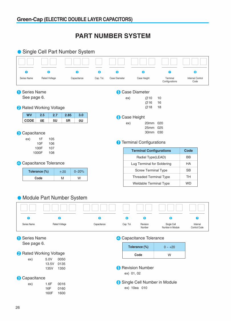
Series NameSee page 6.
Rated Working Voltage
Capacitanceex) 1F 105
10F 106100F 107
1000F 108
Capacitance Tolerance
Case Diameterex) 10 10
16 1618 18
Case Heightex) 20mm 020
25mm 02530mm 030
Terminal Configurations
WV
CODE
2.5
0E
2.7
5U
2.85
5R
3.0
0U
Terminal Configurations
Radial Type(LEAD)
Lug Terminal for Soldering
Screw Terminal Type
Threaded Terminal Type
Weldable Terminal Type
Code
BB
HA
SB
TH
WD
Tolerance (%)
Code
20
M
0~20%
W
Single Cell Part Number System
Series Name Rated Voltage Capacitance Cap. Tol. Case Diameter Case Height TerminalConfigurations
Internal Control Code
Series NameSee page 6.
Rated Working Voltageex) 5.0V 0050
13.5V 0135135V 1350
Capacitanceex) 1.6F 0016
16F 0160160F 1600
Capacitance Tolerance
Revision Numberex) 01, 02
Single Cell Number in Moduleex) 10ea 010
Tolerance (%)
Code
0 ~ +20
W
Module Part Number System
Series Name Rated Voltage Capacitance Cap. Tol. RevisionNumber
Single CellNumber in Module
InternalControl Code
PART NUMBER SYSTEM

27
Green-Cap (ELECTRIC DOUBLE LAYER CAPACITORS)
PACKING
FIGURE 1
SNAP-IN TYPE INNER, MIDDLE BOX
FIGURE 2
AXIAL TYPE BOX
SNAP-IN TYPE(DB series) PACKING Quantity (pcs) / BOX(FIGURE 1)
22
30
35
35, 45
45
60
50 ~ 60
150
50
50
50
450
200
150
150
SIZE SNAP-IN(QUANTITY)
D L INNER BOX MIDDLE BOX
8
10
16
18
20
20
30
25
40
300
200
200
50
50
2400
1600
1200
500
300
9600
6400
4800
2000
1200
SIZE BULK(QUANTITY)
D L V-Bag INNER BOX MIDDLE BOX
AXIAL TYPE(DH series) PACKING Quantity (pcs) / BOX (FIGURE 2)
60 51 ~ 138 20
SIZE
D L AXIAL(QUANTITY)
BLUCK TYPE PACKING
RADIAL TYPE PACKINGDS series BULK PACKING QUANTITY(pcs) / BOX
Green-C
ap(E
DLC
)

28
Green-Cap (ELECTRIC DOUBLE LAYER CAPACITORS)
Low internal resistanceBalancing and overvoltage protection of individual cellEfficient heat transfer to outside
Application
Next Generation Vehicle(FCEV,HEV) & Heavy Duty TransportationShort term UPS and telecommunicationsPortable Power ToolWind Turbine Pitch SystemElectric ScooterHeavy Duty TransportationGolf Car
Green-Cap Module
DM
Item CharacteristicsCapacitance tolerance
Operating temperature range
Storage Temperature Range
Temperature characteristics
Endurance (65 C)
Shelf life (65 C)
Life Time at RT (1) (2)
(held continuously at Rated Voltage)
Cycle Life (25 C) (1) (2) (3)
0% ~ +20%
-40 ~ +65 C, -40 ~ +85 C
-40 ~ +70 C
Part NumberRated
VoltageCapacitance
(F)
ESR,1KHz(mΩ)
ESR,DC
(mΩ)
Max. PeakCurrent
(A)
Max. ContinuousCurrent (A)
Weight
(kg)
Max.StoredEnergy
(Wh)
SpecificEnergy
(Wh/kg)
Dimension(mm)
L W H
5.4
5.4
5.4
15
16.2
16.2
16.2
16.2
48.6
48.6
48.6
48.6
75
90
129.6
1.5
2.5
5.0
66.6
200
266.6
333.3
500
66.6
88.8
111.1
166.6
36
10
62.5
120
100
60
23.0
2.5
2.2
1.8
1.4
7.6
6.5
5.4
4.3
38.4
138.2
11.5
180
140
100
27.4
3.6
3.2
2.5
2.0
10.8
9.7
7.6
6.0
45.6
164.2
16.1
3.2
5.0
9.0
191.0
941.8
1165.4
1472.7
2025.0
941.8
1165.4
1472.7
2025.0
511.0
170.3
2025.0
0.20
0.33
0.65
22.9
63
85
106
150
63
85
106
150
62.4
20.8
150
0.006
0.010
0.020
2.08
7.29
9.72
12.15
18.23
21.87
29.16
36.45
54.68
28.13
11.25
145.80
1.79
2.03
2.89
2.60
1.78
2.11
2.38
3.04
2.19
2.54
2.92
3.65
2.25
1.41
2.43
22.0
22.0
32.0
247
418
418
418
418
418
418
418
418
460
290
715
8.5
10.5
10.5
46
68
68
68
68
191
191
191
191
153
110
500
16.5
21.0
21.0
76
115
126
143
179
115
126
143
179
282
268
310
0.0034
0.005
0.007
0.8
4.1
4.6
5.1
6
10
11.5
12.5
15
12.5
8
60
Cycle LifeCapacitance
change
DM00540015W01002
DM00540025W01002
DM00540050W01002
DM01500666W01006
DM01622000W01006
DM01622666W01006
DM01623333W01006
DM01625000W01006
DM04860666W01018
DM04860888W01018
DM04861111W01018
DM04861666W01018
DM07500360W01090
DM09000100W01036
DM12960625W01048
Product & Spec.
Test time
Capacitance change
Internal resistance change
1500 hours (5.4V products are for 1000 hours)Within 30% of initial specified valueWithin 20% of initial specified value
Less than 100% of specified value
Capacitance changeInternal resistance change
Within 5% of initial value at +20 CWithin 150% of initial value at +20 C
After 1500 hours no load test same as endurance
(3) Cycle : between rated voltage and half rated voltage under constant current at 25 C
(1)
(2)
10 years
500,000 cycles
1,000,000 cycles
Note : Other Green-Cap modules are supplied on custom-made basis. Dimension and Weight could be changed.The contents of this document are subject to change without notice.

29
Green-Cap (ELECTRIC DOUBLE LAYER CAPACITORS)
H( 0.2)13.0
D1( 0.2)
60.4
D2( 0.5)
60.7
Size(mm)
H L 1.0 H
D1D2 M12 1.75M12 1.75
M12
(-) (+)
Unit : mm
High Power DensityRapid charge and dischargeUltra-low internal resistance
Axial Type, Standard SeriesDH
Item CharacteristicsOperating temperature rangeRated VoltageCapacitance tolerance
Temperature characteristics
Endurance (65 C)
Shelf life (65 C)
Life Time at RT (1)
Cycle Life (25 C) (1)(2)
-40 ~ +65 C 2.7 VDC0% ~ +20%
Test timeCapacitance changeInternal resistance change
1500 hoursWithin 20% of specified valueLess than 100% of specified value
Capacitance changeInternal resistance change
Within 5% of initial value at +20 C Within 100% of initial value at +20 C
After 1500 hours no load test same as endurance
DRAWING
(1) I CI 20% and ESR 100% of specified value,respectively and LC specified value
(2) Cycle : between rated voltage and half rated voltage under constant current at 25 C
10 years
1,000,000 cycles
CHARACTERISTIC LIST & DIMENSIONS
RatedVoltage
Capacitance(F)
ESR, 1KHz(mΩ)
LC (72hr)(mA)
Max ContinuousCurrent(A)
Max PeakCurrent(A)
Weight(g)
Volume(ml)(Wh/kg) (Wh/L)
Specific Energy DimensionD L(mm)
2.7
1200
1600
2000
3000
0.35
0.30
0.25
0.20
ESR, DC(mΩ)
0.50
0.45
0.35
0.28
2.7
3.2
4.2
5.2
63
85
106
150
1013
1256
1588
2201
4.19
4.98
5.26
5.90
5.73
6.65
6.93
7.68
290
325
385
515
212
244
292
395
60.4
60.4
60.4
60.4
74
85
102
138
17 0-- 0.05
17
170
-- 0.05
H
L 1.0
H
D1D2 (-) (+) H( 0.2)
3.0
D1( 0.2)
60.4
D2( 0.5)
60.7
Size(mm)
Threaded Type
Weldable Type
Green-C
ap(E
DLC
)

30
Green-Cap (ELECTRIC DOUBLE LAYER CAPACITORS)
H( 0.2)13.0
D1( 0.2)
60.4
D2( 0.5)
60.7
Size(mm)
H L 1.0 H
D1D2 M12 1.75M12 1.75
M12
(-) (+)
Unit : mm
High Power DensityRapid charge and dischargeUltra-low internal resistance
Axial Type, High Voltage SeriesDV
Item CharacteristicsOperating temperature rangeRated VoltageCapacitance tolerance
Temperature characteristics
Endurance (65 C)
Shelf life (65 C)
Life Time at RT (1)
Cycle Life (25 C) (1)(2)
-40 ~ +65 C 2.85 VDC0% ~ +20%
Test timeCapacitance changeInternal resistance change
1500 hoursWithin 20% of specified valueLess than 100% of specified value
Capacitance changeInternal resistance change
Within 5% of initial value at +20 C Within 100% of initial value at +20 C
After 1500 hours no load test same as endurance
DRAWING
(1) I CI 20% and ESR 100% of specified value,respectively and LC specified value
(2) Cycle : between rated voltage and half rated voltage under constant current at 25 C
10 years
1,000,000 cycles
CHARACTERISTIC LIST & DIMENSIONS
RatedVoltage
Capacitance(F)
ESR, 1KHz(mΩ)
LC (72hr)(mA)
Max ContinuousCurrent(A)
Max PeakCurrent(A)
Weight(g)
Volume(ml)(Wh/kg) (Wh/L)
Specific Energy DimensionD L(mm)
2.85
1200
1600
2000
3000
0.35
0.30
0.25
0.20
ESR, DC(mΩ)
0.50
0.45
0.35
0.28
3.4
4.6
5.7
8.6
63
84
106
150
1069
1326
1676
2323
4.67
5.55
5.86
6.57
6.38
7.41
7.72
8.56
290
325
385
515
212
244
292
395
60.4
60.4
60.4
60.4
74
85
102
138
17 0-- 0.05
17
170
-- 0.05
H
L 1.0
H
D1D2 (-) (+) H( 0.2)
3.0
D1( 0.2)
60.4
D2( 0.5)
60.7
Size(mm)
Threaded Type
Weldable Type

31
Green-Cap (ELECTRIC DOUBLE LAYER CAPACITORS)
H( 0.2)13.0
D1( 0.2)
60.4
D2( 0.5)
60.7
Size(mm)
H L 1.0 H
D1D2 M12 1.75M12 1.75
M12
(-) (+)
Unit : mm
High Power DensityRapid charge and dischargeUltra-low internal resistance
Axial Type, High Temperature SeriesDT
Item CharacteristicsOperating temperature rangeRated VoltageCapacitance tolerance
Temperature characteristics
Endurance (85 C)
Shelf life (85 C)
Life Time at RT (1)
Cycle Life (25 C) (1)(2)
-40 ~ +85 C 2.5 VDC0% ~ +20%
Test timeCapacitance changeInternal resistance change
1500 hoursWithin 20% of specified valueLess than 100% of specified value
Capacitance changeInternal resistance change
Within 5% of initial value at +20 C Within 100% of initial value at +20 C
After 1500 hours no load test same as endurance
DRAWING
(1) I CI 20% and ESR 100% of specified value,respectively and LC specified value
(2) Cycle : between rated voltage and half rated voltage under constant current at 25 C
10 years
1,000,000 cycles
CHARACTERISTIC LIST & DIMENSIONS
RatedVoltage
Capacitance(F)
ESR, 1KHz(mΩ)
LC (72hr)(mA)
Max ContinuousCurrent(A)
Max PeakCurrent(A)
Weight(g)
Volume(ml)(Wh/kg) (Wh/L)
Specific Energy DimensionD L(mm)
2.5
1200
1600
2000
3000
0.35
0.30
0.25
0.20
ESR, DC(mΩ)
0.50
0.45
0.35
0.28
3.0
4.0
5.0
7.5
63
84
106
150
938
1163
1471
2038
3.59
4.27
4.51
5.06
4.91
5.70
5.94
6.59
290
325
385
515
212
244
292
395
60.4
60.4
60.4
60.4
74
85
102
138
17 0-- 0.05
17
170
-- 0.05
H
L 1.0
H
D1D2 (-) (+) H( 0.2)
3.0
D1( 0.2)
60.4
D2( 0.5)
60.7
Size(mm)
Threaded Type
Weldable Type
Green-C
ap(E
DLC
)

32
Green-Cap (ELECTRIC DOUBLE LAYER CAPACITORS)
Item CharacteristicsOperating temperature rangeRated VoltageCapacitance tolerance
Temperature characteristics
Endurance(2.5V:70 C, 2.7V:65 C)
Shelf life(2.5V:70 C, 2.7V:65 C)
Life Time at RT (1)
Cycle Life (25 C) (1)(2)
-25 ~ +70 C 2.5 VDC-20 ~ +20% or 0% ~ +20% at 20 C
-40 ~ +65 C 2.7 VDC
Test timeCapacitance changeInternal resistance change
1500 hoursWithin 30% of specified valueLess than 100% of specified value
Capacitance changeInternal resistance change
Within 5% of initial value at +20 CWithin 50% of initial value at +20 C
After 1500 hours no load test same as endurance
(1) I CI 30% and ESR 100% of specified value,respectively and LC specified value
(2) Cycle : between rated voltage and half rated voltage under constant current at 25 C
10 years
500,000 cycles
Endurance : 2.5V 70 C 1500 hours, 2.7V 65 C 1500 hoursThe middle size and high capacitance, low resistanceCharge and discharge efficiency are higher than in batteries
Snap-in Terminal Type,Standard SeriesDB
DRAWING Unit : mm
CHARACTERISTIC LIST & DIMENSIONS
RatedVoltage
Capacitance(F)
ESR, 1KHz(mΩ)
LC (72hr)(mA Max.)
Max ContinuousCurrent(A)
Max PeakCurrent(A)
Weight(g)
Volume(ml)(Wh/kg) (Wh/L)
Specific Energy DimensionD L(mm)
2.5
2.7
100
200
300
360
400
100
200
300
360
400
15.0
10.0
6.0
6.0
6.0
8.0
7.0
3.5
3.2
3.2
ESR, DC(mΩ)
35.0
20.0
15.0
12.0
10.0
10.0
9.0
5.0
3.8
3.8
0.25
0.50
0.75
0.90
1.0
0.26
0.54
0.91
0.97
1.08
5.3
10.4
15.3
18.5
20.8
6.4
12.3
18.8
22.7
25
27.7
50.0
68.2
84.6
100.0
67.5
96.4
162.0
205.2
214.2
3.62
4.13
4.20
4.17
4.63
4.82
5.33
5.33
5.21
5.79
5.07
5.46
5.41
5.41
6.01
5.92
6.37
6.31
6.31
7.02
24
42
62
75
75
21
38
57
70
70
17
32
48
58
58
17
32
48
58
58
22
30
35
35
35
22
30
35
35
35
45
45
50
60
60
45
45
50
60
60
PC BoardMounting Holes
Terminal
10
Bottom plate
Safety vent
Insulating sleeve
Terminal
2 2 0.1
D1
max
.
L 3 max.
0.8 0.1
1.5 0.1
0.8 0.1
6.0 1
100.2
6 1(4.0 0.5)
35 4 pin type terminal drawing is same see pages 200.

33
Green-Cap (ELECTRIC DOUBLE LAYER CAPACITORS)
Unit : mm
Endurance : 2.5V 85 C 1500 hoursThe middle size and high capacitance, low resistanceCharge and discharge efficiency are higher than in batteries
Snap-in Terminal Type,High Temperature SeriesDK
Item CharacteristicsOperating temperature rangeRated VoltageCapacitance tolerance
Temperature characteristics
Endurance (85 C)
Shelf life (85 C)
Life Time at RT (1)
Cycle Life (25 C) (1)(2)
-40 ~ +85 C 2.5 VDC0% ~ +20%
Test timeCapacitance changeInternal resistance change
1500 hoursWithin 30% of specified valueLess than 100% of specified value
Capacitance changeInternal resistance change
Within 5% of initial value at +20 C Within 50% of initial value at +20 C
After 1500 hours no load test same as endurance
DRAWING
(1) I CI 30% and ESR 100% of specified value,respectively and LC specified value
(2) Cycle : between rated voltage and half rated voltage under constant current at 25 C
10 years
500,000 cycles
PC BoardMounting Holes
Terminal
10
Bottom plate
Safety vent
Insulating sleeve
Terminal
2 2 0.1
D1
max
.
L 3 max.
0.8 0.1
1.5 0.1
0.8 0.1
6.0 1
100.2
6 1(4.0 0.5)
CHARACTERISTIC LIST & DIMENSIONS
RatedVoltage
Capacitance(F)
ESR, 1KHz(mΩ)
LC (72hr)(mA Max.)
Max ContinuousCurrent(A)
Max PeakCurrent(A)
Weight(g)
Volume(ml)(Wh/kg) (Wh/L)
Specific Energy DimensionD L(mm)
2.5
100
200
300
360
400
8.0
7.0
3.5
3.2
3.2
ESR, DC(mΩ)
10.0
9.0
5.0
3.8
3.8
0.25
0.50
0.75
0.90
1.00
5.3
10.6
15.8
19
21.1
63
89
150
190
198
4.13
4.57
4.57
4.46
4.96
5.07
5.46
5.41
5.41
6.01
21
38
57
70
70
17
32
48
58
58
22
30
35
35
35
45
45
50
60
60
35 4pin type terminal drawing is same see pages 200.
Green-C
ap(E
DLC
)
34
Green-Cap (ELECTRIC DOUBLE LAYER CAPACITORS)
Unit : mm
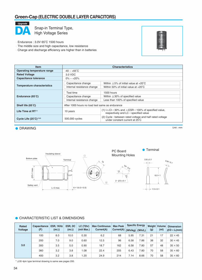
Endurance : 3.0V 65 C 1500 hoursThe middle size and high capacitance, low resistanceCharge and discharge efficiency are higher than in batteries
Snap-in Terminal Type,High Voltage SeriesDA
Item CharacteristicsOperating temperature rangeRated VoltageCapacitance tolerance
Temperature characteristics
Endurance (65 C)
Shelf life (65 C)
Life Time at RT (1)
Cycle Life (25 C) (1)(2)
-40 ~ +65 C 3.0 VDC0% ~ +20%
Test timeCapacitance changeInternal resistance change
1500 hoursWithin 30% of specified valueLess than 100% of specified value
Capacitance changeInternal resistance change
Within 5% of initial value at +20 C Within 50% of initial value at +20 C
After 1000 hours no load test same as endurance
DRAWING
(1) I CI 30% and ESR 100% of specified value,respectively and LC specified value
(2) Cycle : between rated voltage and half rated voltage under constant current at 25 C
35 4pin type terminal drawing is same see pages 200.
10 years
500,000 cycles
PC BoardMounting Holes
Terminal
10
Bottom plate
Safety vent
Insulating sleeve
Terminal
2 2 0.1
D1
max
.
L 3 max.
0.8 0.1
1.5 0.1
0.8 0.1
6.0 1
100.2
6 1(4.0 0.5)
CHARACTERISTIC LIST & DIMENSIONS
RatedVoltage
Capacitance(F)
ESR, 1KHz(mΩ)
LC (72hr)(mA Max.)
Max ContinuousCurrent(A)
Max PeakCurrent(A)
Weight(g)
Volume(ml)(Wh/kg) (Wh/L)
Specific Energy DimensionD L(mm)
3.0
100
200
300
360
400
8.0
7.0
3.5
3.2
3.2
ESR, DC(mΩ)
10.0
9.0
5.0
3.8
3.8
0.30
0.60
0.90
1.08
1.20
6.2
12.5
18.7
22.4
24.9
68
96
162
205
214
5.95
6.58
6.58
6.43
7.14
7.31
7.86
7.80
7.80
8.66
21
38
57
70
70
17
32
48
58
58
22
30
35
35
35
45
45
50
60
60
Upgrade

35
Green-Cap (ELECTRIC DOUBLE LAYER CAPACITORS)
Unit : mm
Dm
ax.
L max. 15 min. 4 min.
P 0.5
Insulating sleeve d 0.05 Tinned copper-ply wire
Safety vent
Endurance : 2.5V 70 C 1000 hours, 2.7V 65 C 1000 hours, 3.0V 65 C 1000 hoursThe small size and high capacitance, low resistanceCan be charge and discharge more times than secondary batteries
Radial Type, Standard SeriesDS
Item CharacteristicsOperating temperature rangeRated VoltageCapacitance tolerance
Temperature characteristics
Endurance (2.5V:70 C, 2.7V:65 C, 3.0V:65 C)
Shelf life (2.5V:70 C, 2.7V:65 C, 3.0V:65 C)
Life Time at RT (1)
Cycle Life (25 C) (1)(2)
-30 ~ +70 C 2.5 VDC
0 ~ +20% at 20 C
-40 ~ +65 C 2.7 VDC
Test timeCapacitance changeInternal resistance change
1000 hoursWithin 30% of specified valueLess than 100% of specified value
-40 ~ +65 C 3.0 VDC
Capacitance changeInternal resistance change
Within 5% of initial value at +20 C Within 50% of initial value at +20 C
After 1000 hours no load test same as endurance
DRAWING
DPd
83.50.61.5
105.00.6
167.50.82.0
187.50.8
(1) I CI 30% and ESR 100% of specified value,respectively and LC specified value
(2) Cycle : between rated voltage and half rated voltage under constant current at 25 C
10 years
500,000 cycles
CHARACTERISTIC LIST & DIMENSIONS
RatedVoltage
Capacitance(F)
ESR, DC(mΩ)
ESR, 1KHz(mΩ)
LC (72hr)(mA Max.)
Weight(g)
Volume(ml)(Wh/kg) (Wh/L) (W/kg) (W/L)
Specific Energy Specific Power DimensionD L(mm)
2.5
2.7
3.0
3
5
10
25
60
3
5
10
25
50
3
5
10
25
60
140
110
65
35
20
60
50
30
20
10
60
50
30
20
10
350
250
120
65
30
90
70
50
35
20
105
90
45
30
20
0.008
0.013
0.025
0.063
0.150
0.008
0.014
0.027
0.068
0.140
0.009
0.015
0.030
0.075
0.180
1.63
1.97
2.48
2.89
3.77
2.17
2.41
3.49
3.78
4.40
2.34
2.84
3.57
4.17
5.43
2.60
2.71
3.62
4.34
5.11
3.04
3.16
4.22
5.06
4.96
3.75
3.91
5.21
6.25
7.35
1,339
1,364
1,786
1,538
1,812
6,943
5,951
6,033
3,730
3,803
6,429
5,455
6,857
4,800
3,913
2,143
1,875
2,604
2,308
2,451
9,720
7,811
7,290
4,999
4,288
10,286
7,500
10,000
7,200
5,294
1.60
2.2
3.5
7.5
13.8
1.4
2.1
2.9
6.7
11.5
1.6
2.2
3.5
7.5
13.8
1.0
1.6
2.4
5.0
10.2
1.0
1.6
2.4
5.0
10.2
1.0
1.6
2.4
5.0
10.2
8
10
10
16
18
8
10
10
16
18
8
10
10
16
18
20
20
30
25
40
20
20
30
25
40
20
20
30
25
40
Green-C
ap(E
DLC
)

36
Green-Cap (ELECTRIC DOUBLE LAYER CAPACITORS)
Unit : mm
D0.
5 m
ax.
L max. 15 min. 4 min.
P 0.5
Insulating sleeve d 0.05 Tinned copper-ply wire
Safety vent
Endurance : 2.5V 85 C 1000 hoursThe small size and high capacitance, low resistanceCan be charge and discharge more times than secondary batteries
Radial Type, High Temperature SeriesDJ
Item CharacteristicsOperating temperature rangeRated VoltageCapacitance tolerance
Temperature characteristics
Endurance (85 C)
Shelf life (85 C)
Life Time at RT (1)
Cycle Life (25 C) (1)(2)
-40 ~ +85 C 2.5 VDC0% ~ +20% at 20 C
Test timeCapacitance changeInternal resistance change
1000 hoursWithin 30% of specified valueLess than 100% of specified value
Capacitance changeInternal resistance change
Within 5% of initial value at +20 C Within 50% of initial value at +20 C
After 1000 hours no load test same as endurance
DRAWING
DPd
83.50.61.5
105.00.6
167.50.82.0
187.50.8
(1) I CI 30% and ESR 100% of specified value,respectively and LC specified value
(2) Cycle : between rated voltage and half rated voltage under constant current at 25 C
10 years
500,000 cycles
CHARACTERISTIC LIST & DIMENSIONS
RatedVoltage
Capacitance(F)
ESR, DC(mΩ)
ESR, 1KHz(mΩ)
LC (72hr)(mA Max.)
Weight(g)
Volume(ml)(Wh/kg) (Wh/L) (W/kg) (W/L)
Specific Energy Specific Power DimensionD L(mm)
2.5
3
5
10
25
60
60
50
30
20
10
105
90
45
30
20
0.008
0.013
0.025
0.063
0.150
1.63
1.97
2.48
2.89
3.77
2.60
2.71
3.62
4.34
5.11
4.464
3.788
4.762
3.333
2.717
7.143
5.208
6.944
5.000
3.676
1.6
2.2
3.5
7.5
13.8
1.0
1.6
2.4
5.0
10.2
8
10
10
16
18
20
20
30
25
40