1 industrial-robotics (1)
TRANSCRIPT

©2008 Pearson Education, Inc., Upper Saddle River, NJ. All rights reserved. This material is protected under all copyright laws as they currently exist. No portion of this material may be reproduced, in any form or by any means, without permission in writing from the publisher. For the exclusive use of adopters of the book
Automation, Production Systems, and Computer-Integrated Manufacturing, Third Edition, by Mikell P. Groover.
Ch 8 Industrial Robotics
Sections:
1. Robot Anatomy and Related Attributes
2. Robot Control Systems
3. End Effectors
4. Sensors in Robotics
5. Industrial Robot Applications
6. Robot Programming
7. Robot Accuracy and Repeatability
©2008 Pearson Education, Inc., Upper Saddle River, NJ. All rights reserved. This material is protected under all copyright laws as they currently exist. No portion of this material may be reproduced, in any form or by any means, without permission in writing from the publisher. For the exclusive use of adopters of the book
Automation, Production Systems, and Computer-Integrated Manufacturing, Third Edition, by Mikell P. Groover.
Industrial Robot Defined
A general-purpose, programmable machine possessing certain anthropomorphic characteristics
Why industrial robots are important: Robots can substitute for humans in hazardous
work environments Consistency and accuracy not attainable by
humans Can be reprogrammed Most robots are controlled by computers and can
therefore be interfaced to other computer systems

©2008 Pearson Education, Inc., Upper Saddle River, NJ. All rights reserved. This material is protected under all copyright laws as they currently exist. No portion of this material may be reproduced, in any form or by any means, without permission in writing from the publisher. For the exclusive use of adopters of the book
Automation, Production Systems, and Computer-Integrated Manufacturing, Third Edition, by Mikell P. Groover.
Robot Anatomy
Manipulator consists of joints and links Joints provide relative motion Links are rigid members between joints Various joint types: linear and rotary Each joint provides a “degree-of-freedom” Most robots possess five or six degrees-of-freedom
Robot manipulator consists of two sections: Body-and-arm – for positioning of objects in the
robot's work volume Wrist assembly – for orientation of objects

©2008 Pearson Education, Inc., Upper Saddle River, NJ. All rights reserved. This material is protected under all copyright laws as they currently exist. No portion of this material may be reproduced, in any form or by any means, without permission in writing from the publisher. For the exclusive use of adopters of the book
Automation, Production Systems, and Computer-Integrated Manufacturing, Third Edition, by Mikell P. Groover.
Robot Anatomy
Robot manipulator - a series of joint-link combinations

©2008 Pearson Education, Inc., Upper Saddle River, NJ. All rights reserved. This material is protected under all copyright laws as they currently exist. No portion of this material may be reproduced, in any form or by any means, without permission in writing from the publisher. For the exclusive use of adopters of the book
Automation, Production Systems, and Computer-Integrated Manufacturing, Third Edition, by Mikell P. Groover.
Types of Manipulator Joints
Translational motion Linear joint (type L) Orthogonal joint (type O)
Rotary motion Rotational joint (type R) Twisting joint (type T) Revolving joint (type V)
©2008 Pearson Education, Inc., Upper Saddle River, NJ. All rights reserved. This material is protected under all copyright laws as they currently exist. No portion of this material may be reproduced, in any form or by any means, without permission in writing from the publisher. For the exclusive use of adopters of the book
Automation, Production Systems, and Computer-Integrated Manufacturing, Third Edition, by Mikell P. Groover.
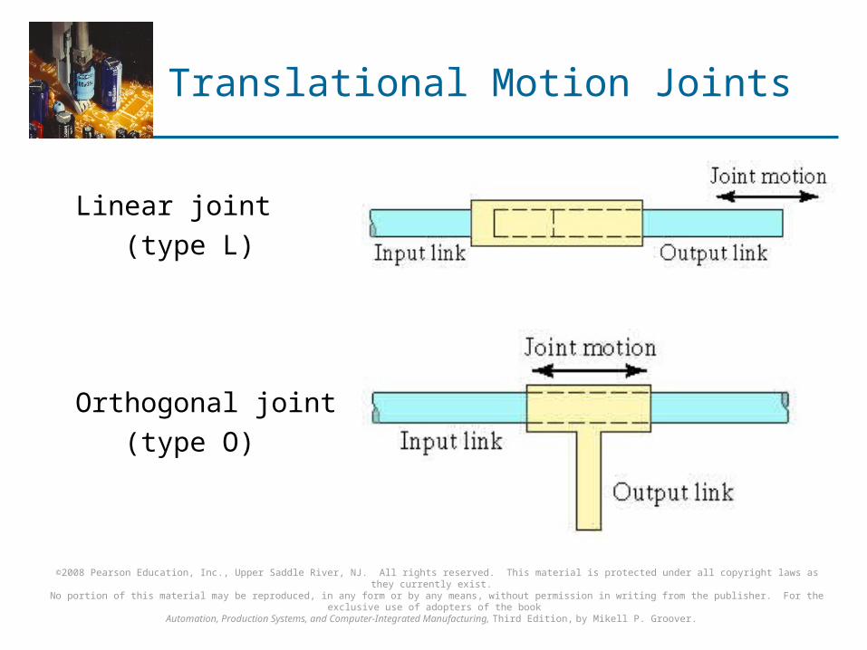
Translational Motion Joints
Linear joint
(type L)
Orthogonal joint
(type O)

©2008 Pearson Education, Inc., Upper Saddle River, NJ. All rights reserved. This material is protected under all copyright laws as they currently exist. No portion of this material may be reproduced, in any form or by any means, without permission in writing from the publisher. For the exclusive use of adopters of the book
Automation, Production Systems, and Computer-Integrated Manufacturing, Third Edition, by Mikell P. Groover.
Rotary Motion Joints
Rotational joint (type R)
Twisting joint
(type T)
Revolving joint
(type V)
©2008 Pearson Education, Inc., Upper Saddle River, NJ. All rights reserved. This material is protected under all copyright laws as they currently exist. No portion of this material may be reproduced, in any form or by any means, without permission in writing from the publisher. For the exclusive use of adopters of the book
Automation, Production Systems, and Computer-Integrated Manufacturing, Third Edition, by Mikell P. Groover.
Joint Notation Scheme
Uses the joint symbols (L, O, R, T, V) to designate joint types used to construct robot manipulator
Separates body-and-arm assembly from wrist assembly using a colon (:)
Example: TLR : TR
©2008 Pearson Education, Inc., Upper Saddle River, NJ. All rights reserved. This material is protected under all copyright laws as they currently exist. No portion of this material may be reproduced, in any form or by any means, without permission in writing from the publisher. For the exclusive use of adopters of the book
Automation, Production Systems, and Computer-Integrated Manufacturing, Third Edition, by Mikell P. Groover.
Robot Body-and-Arm Configurations
Five common body-and-arm configurations for industrial robots:
1. Polar coordinate body-and-arm assembly
2. Cylindrical body-and-arm assembly
3. Cartesian coordinate body-and-arm assembly
4. Jointed-arm body-and-arm assembly
5. Selective Compliance Assembly Robot Arm (SCARA) Function of body-and-arm assembly is to position an end
effector (e.g., gripper, tool) in space
©2008 Pearson Education, Inc., Upper Saddle River, NJ. All rights reserved. This material is protected under all copyright laws as they currently exist. No portion of this material may be reproduced, in any form or by any means, without permission in writing from the publisher. For the exclusive use of adopters of the book
Automation, Production Systems, and Computer-Integrated Manufacturing, Third Edition, by Mikell P. Groover.
Polar Coordinate Body-and-Arm Assembly
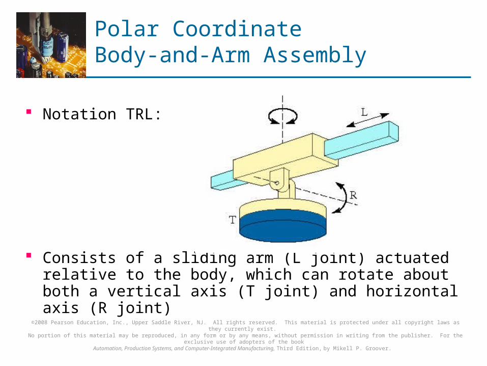
Notation TRL:
Consists of a sliding arm (L joint) actuated relative to the body, which can rotate about both a vertical axis (T joint) and horizontal axis (R joint)

©2008 Pearson Education, Inc., Upper Saddle River, NJ. All rights reserved. This material is protected under all copyright laws as they currently exist. No portion of this material may be reproduced, in any form or by any means, without permission in writing from the publisher. For the exclusive use of adopters of the book
Automation, Production Systems, and Computer-Integrated Manufacturing, Third Edition, by Mikell P. Groover.
Cylindrical Body-and-Arm Assembly
Notation TLO:
Consists of a vertical column, relative to which an arm assembly is moved up or down
The arm can be moved in or out relative to the column
©2008 Pearson Education, Inc., Upper Saddle River, NJ. All rights reserved. This material is protected under all copyright laws as they currently exist. No portion of this material may be reproduced, in any form or by any means, without permission in writing from the publisher. For the exclusive use of adopters of the book
Automation, Production Systems, and Computer-Integrated Manufacturing, Third Edition, by Mikell P. Groover.
Cartesian Coordinate Body-and-Arm Assembly
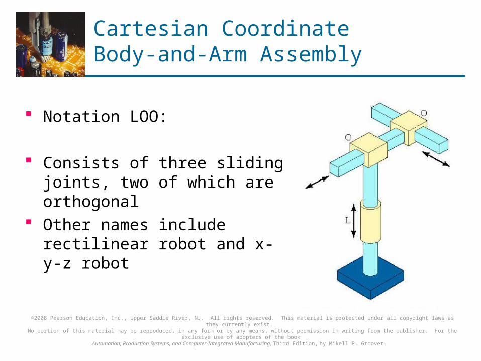
Notation LOO:
Consists of three sliding joints, two of which are orthogonal
Other names include rectilinear robot and x-y-z robot
©2008 Pearson Education, Inc., Upper Saddle River, NJ. All rights reserved. This material is protected under all copyright laws as they currently exist. No portion of this material may be reproduced, in any form or by any means, without permission in writing from the publisher. For the exclusive use of adopters of the book
Automation, Production Systems, and Computer-Integrated Manufacturing, Third Edition, by Mikell P. Groover.
Jointed-Arm Robot
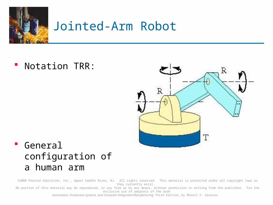
Notation TRR:
General configuration of a human arm
©2008 Pearson Education, Inc., Upper Saddle River, NJ. All rights reserved. This material is protected under all copyright laws as they currently exist. No portion of this material may be reproduced, in any form or by any means, without permission in writing from the publisher. For the exclusive use of adopters of the book
Automation, Production Systems, and Computer-Integrated Manufacturing, Third Edition, by Mikell P. Groover.
SCARA Robot
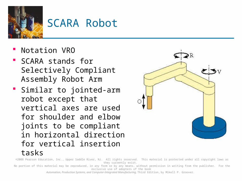
Notation VRO SCARA stands for Selectively
Compliant Assembly Robot Arm
Similar to jointed-arm robot except that vertical axes are used for shoulder and elbow joints to be compliant in horizontal direction for vertical insertion tasks

©2008 Pearson Education, Inc., Upper Saddle River, NJ. All rights reserved. This material is protected under all copyright laws as they currently exist. No portion of this material may be reproduced, in any form or by any means, without permission in writing from the publisher. For the exclusive use of adopters of the book
Automation, Production Systems, and Computer-Integrated Manufacturing, Third Edition, by Mikell P. Groover.
Wrist Configurations
Wrist assembly is attached to end-of-arm End effector is attached to wrist assembly Function of wrist assembly is to orient end effector
Body-and-arm determines global position of end effector
Two or three degrees of freedom: Roll Pitch Yaw

©2008 Pearson Education, Inc., Upper Saddle River, NJ. All rights reserved. This material is protected under all copyright laws as they currently exist. No portion of this material may be reproduced, in any form or by any means, without permission in writing from the publisher. For the exclusive use of adopters of the book
Automation, Production Systems, and Computer-Integrated Manufacturing, Third Edition, by Mikell P. Groover.
Wrist Configuration
Typical wrist assembly has two or three degrees-of-freedom (shown is a three degree-of freedom wrist)
Notation :RRT
©2008 Pearson Education, Inc., Upper Saddle River, NJ. All rights reserved. This material is protected under all copyright laws as they currently exist. No portion of this material may be reproduced, in any form or by any means, without permission in writing from the publisher. For the exclusive use of adopters of the book
Automation, Production Systems, and Computer-Integrated Manufacturing, Third Edition, by Mikell P. Groover.
Joint Drive Systems
Electric Uses electric motors to actuate individual joints Preferred drive system in today's robots
Hydraulic Uses hydraulic pistons and rotary vane actuators Noted for their high power and lift capacity
Pneumatic Typically limited to smaller robots and simple material
transfer applications

©2008 Pearson Education, Inc., Upper Saddle River, NJ. All rights reserved. This material is protected under all copyright laws as they currently exist. No portion of this material may be reproduced, in any form or by any means, without permission in writing from the publisher. For the exclusive use of adopters of the book
Automation, Production Systems, and Computer-Integrated Manufacturing, Third Edition, by Mikell P. Groover.
Robot Control Systems
Limited sequence control – pick-and-place operations using mechanical stops to set positions
Playback with point-to-point control – records work cycle as a sequence of points, then plays back the sequence during program execution
Playback with continuous path control – greater memory capacity and/or interpolation capability to execute paths (in addition to points)
Intelligent control – exhibits behavior that makes it seem intelligent, e.g., responds to sensor inputs, makes decisions, communicates with humans
©2008 Pearson Education, Inc., Upper Saddle River, NJ. All rights reserved. This material is protected under all copyright laws as they currently exist. No portion of this material may be reproduced, in any form or by any means, without permission in writing from the publisher. For the exclusive use of adopters of the book
Automation, Production Systems, and Computer-Integrated Manufacturing, Third Edition, by Mikell P. Groover.
Robot Control System
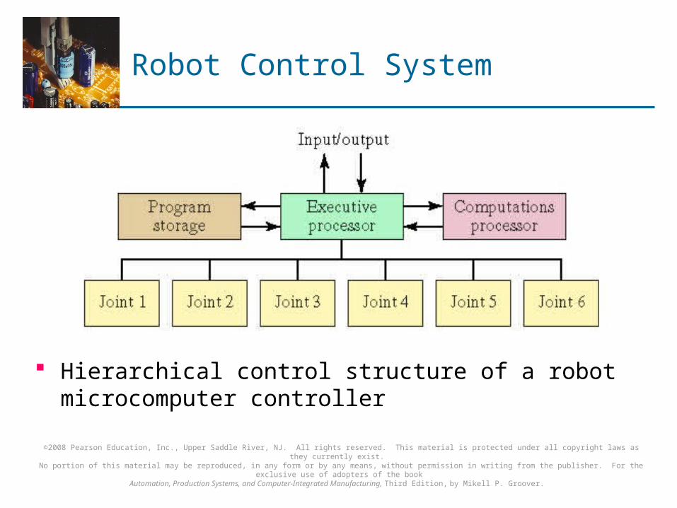
Hierarchical control structure of a robot microcomputer controller

©2008 Pearson Education, Inc., Upper Saddle River, NJ. All rights reserved. This material is protected under all copyright laws as they currently exist. No portion of this material may be reproduced, in any form or by any means, without permission in writing from the publisher. For the exclusive use of adopters of the book
Automation, Production Systems, and Computer-Integrated Manufacturing, Third Edition, by Mikell P. Groover.
End Effectors
The special tooling for a robot that enables it to perform a specific task
Two types: Grippers – to grasp and manipulate objects (e.g.,
parts) during work cycle Tools – to perform a process, e.g., spot welding,
spray painting
©2008 Pearson Education, Inc., Upper Saddle River, NJ. All rights reserved. This material is protected under all copyright laws as they currently exist. No portion of this material may be reproduced, in any form or by any means, without permission in writing from the publisher. For the exclusive use of adopters of the book
Automation, Production Systems, and Computer-Integrated Manufacturing, Third Edition, by Mikell P. Groover.
Robot Mechanical Gripper
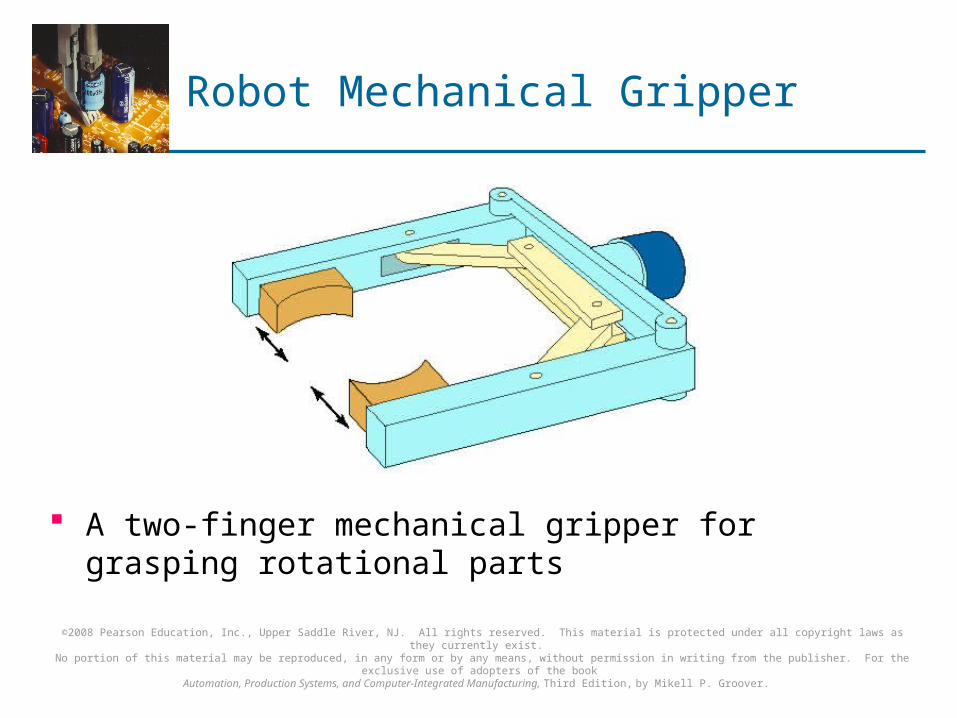
A two-finger mechanical gripper for grasping rotational parts
©2008 Pearson Education, Inc., Upper Saddle River, NJ. All rights reserved. This material is protected under all copyright laws as they currently exist. No portion of this material may be reproduced, in any form or by any means, without permission in writing from the publisher. For the exclusive use of adopters of the book
Automation, Production Systems, and Computer-Integrated Manufacturing, Third Edition, by Mikell P. Groover.
Advances in Mechanical Grippers
Dual grippers Interchangeable fingers Sensory feedback
To sense presence of object To apply a specified force on the object
Multiple fingered gripper (similar to human hand) Standard gripper products to reduce the amount of
custom design required

©2008 Pearson Education, Inc., Upper Saddle River, NJ. All rights reserved. This material is protected under all copyright laws as they currently exist. No portion of this material may be reproduced, in any form or by any means, without permission in writing from the publisher. For the exclusive use of adopters of the book
Automation, Production Systems, and Computer-Integrated Manufacturing, Third Edition, by Mikell P. Groover.
Sensors in Robotics
Two basic categories of sensors used in industrial robots:
1. Internal - used to control position and velocity of the manipulator joints
2. External - used to coordinate the operation of the robot with other equipment in the work cell Tactile - touch sensors and force sensors Proximity - when an object is close to the sensor Optical - Machine vision Other sensors - temperature, voltage, etc.
©2008 Pearson Education, Inc., Upper Saddle River, NJ. All rights reserved. This material is protected under all copyright laws as they currently exist. No portion of this material may be reproduced, in any form or by any means, without permission in writing from the publisher. For the exclusive use of adopters of the book
Automation, Production Systems, and Computer-Integrated Manufacturing, Third Edition, by Mikell P. Groover.
Robot Application Characteristics
General characteristics of industrial work situations that promote the use of industrial robots
1. Hazardous work environment for humans
2. Repetitive work cycle
3. Difficult handling task for humans
4. Multishift operations
5. Infrequent changeovers
6. Part position and orientation are established in the work cell

©2008 Pearson Education, Inc., Upper Saddle River, NJ. All rights reserved. This material is protected under all copyright laws as they currently exist. No portion of this material may be reproduced, in any form or by any means, without permission in writing from the publisher. For the exclusive use of adopters of the book
Automation, Production Systems, and Computer-Integrated Manufacturing, Third Edition, by Mikell P. Groover.
Industrial Robot Applications
1. Material handling applications Material transfer – pick-and-place, palletizing Machine loading and/or unloading
2. Processing operations Spot welding and continuous arc welding Spray coating Other – waterjet cutting, laser cutting, grinding
3. Assembly and inspection

©2008 Pearson Education, Inc., Upper Saddle River, NJ. All rights reserved. This material is protected under all copyright laws as they currently exist. No portion of this material may be reproduced, in any form or by any means, without permission in writing from the publisher. For the exclusive use of adopters of the book
Automation, Production Systems, and Computer-Integrated Manufacturing, Third Edition, by Mikell P. Groover.
Arrangement of Cartons on Pallet

©2008 Pearson Education, Inc., Upper Saddle River, NJ. All rights reserved. This material is protected under all copyright laws as they currently exist. No portion of this material may be reproduced, in any form or by any means, without permission in writing from the publisher. For the exclusive use of adopters of the book
Automation, Production Systems, and Computer-Integrated Manufacturing, Third Edition, by Mikell P. Groover.
Robotic Arc-Welding Cell
Robot performs flux-cored arc welding (FCAW) operation at one workstation while fitter changes parts at the other workstation

©2008 Pearson Education, Inc., Upper Saddle River, NJ. All rights reserved. This material is protected under all copyright laws as they currently exist. No portion of this material may be reproduced, in any form or by any means, without permission in writing from the publisher. For the exclusive use of adopters of the book
Automation, Production Systems, and Computer-Integrated Manufacturing, Third Edition, by Mikell P. Groover.
Robot Programming
Leadthrough programming - work cycle is taught to robot by moving the manipulator through the required motion cycle and simultaneously entering the program into controller memory for later playback
Robot programming languages - uses textual programming language to enter commands into robot controller
Simulation and off-line programming – program is prepared at a remote computer terminal and downloaded to robot controller for execution without need for leadthrough methods
©2008 Pearson Education, Inc., Upper Saddle River, NJ. All rights reserved. This material is protected under all copyright laws as they currently exist. No portion of this material may be reproduced, in any form or by any means, without permission in writing from the publisher. For the exclusive use of adopters of the book
Automation, Production Systems, and Computer-Integrated Manufacturing, Third Edition, by Mikell P. Groover.
Leadthrough Programming
Two types:
1. Powered leadthrough Common for point-to-point robots Uses teach pendant to move joints to desired position
and record that position into memory
2. Manual leadthrough Convenient for continuous path control robots Human programmer physical moves manipulator
through motion cycle and records cycle into memory

©2008 Pearson Education, Inc., Upper Saddle River, NJ. All rights reserved. This material is protected under all copyright laws as they currently exist. No portion of this material may be reproduced, in any form or by any means, without permission in writing from the publisher. For the exclusive use of adopters of the book
Automation, Production Systems, and Computer-Integrated Manufacturing, Third Edition, by Mikell P. Groover.
Teach Pendant for Powered Leadthrough Programming
©2008 Pearson Education, Inc., Upper Saddle River, NJ. All rights reserved. This material is protected under all copyright laws as they currently exist. No portion of this material may be reproduced, in any form or by any means, without permission in writing from the publisher. For the exclusive use of adopters of the book
Automation, Production Systems, and Computer-Integrated Manufacturing, Third Edition, by Mikell P. Groover.
Leadthrough Programming Advantages
Advantages: Can readily be learned by shop personnel A logical way to teach a robot Does not required knowledge of computer
programming Disadvantages:
Downtime - Regular production must be interrupted to program the robot
Limited programming logic capability Not readily compatible with modern computer-based
technologies
©2008 Pearson Education, Inc., Upper Saddle River, NJ. All rights reserved. This material is protected under all copyright laws as they currently exist. No portion of this material may be reproduced, in any form or by any means, without permission in writing from the publisher. For the exclusive use of adopters of the book
Automation, Production Systems, and Computer-Integrated Manufacturing, Third Edition, by Mikell P. Groover.
Robot Programming Languages
Textural programming languages provide the opportunity to perform the following functions that leadthrough programming cannot readily accomplish:
Enhanced sensor capabilities Improved output capabilities to control external equipment Program logic not provided by leadthrough methods Computations and data processing similar to computer
programming languages Communications with other computer systems

©2008 Pearson Education, Inc., Upper Saddle River, NJ. All rights reserved. This material is protected under all copyright laws as they currently exist. No portion of this material may be reproduced, in any form or by any means, without permission in writing from the publisher. For the exclusive use of adopters of the book
Automation, Production Systems, and Computer-Integrated Manufacturing, Third Edition, by Mikell P. Groover.
World Coordinate System
Origin and axes of robot manipulator are defined relative to the robot base
©2008 Pearson Education, Inc., Upper Saddle River, NJ. All rights reserved. This material is protected under all copyright laws as they currently exist. No portion of this material may be reproduced, in any form or by any means, without permission in writing from the publisher. For the exclusive use of adopters of the book
Automation, Production Systems, and Computer-Integrated Manufacturing, Third Edition, by Mikell P. Groover.
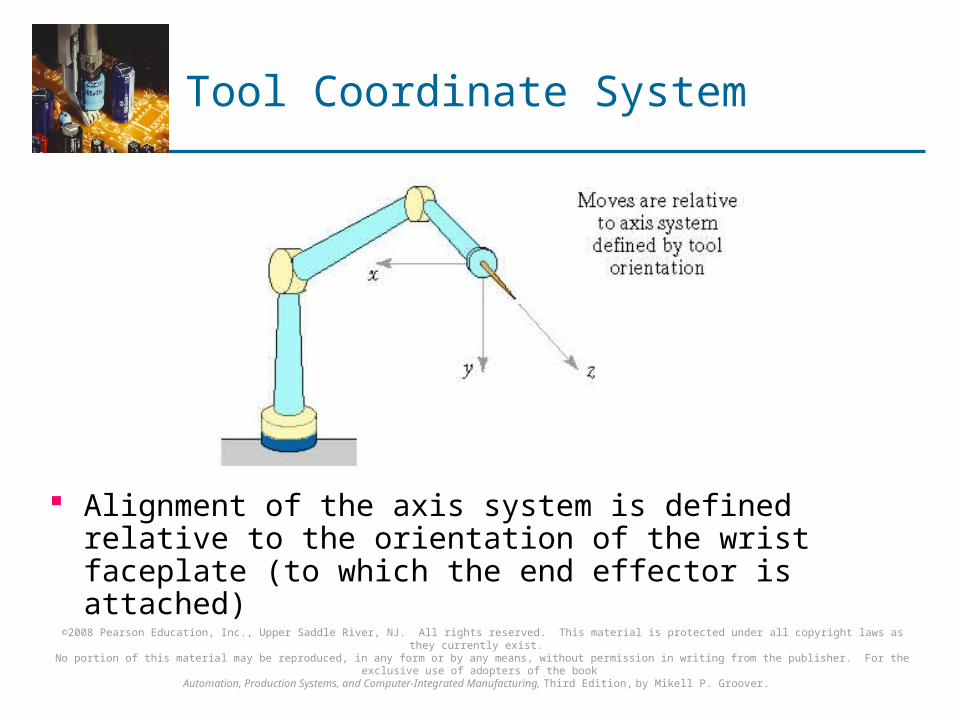
Tool Coordinate System
Alignment of the axis system is defined relative to the orientation of the wrist faceplate (to which the end effector is attached)

©2008 Pearson Education, Inc., Upper Saddle River, NJ. All rights reserved. This material is protected under all copyright laws as they currently exist. No portion of this material may be reproduced, in any form or by any means, without permission in writing from the publisher. For the exclusive use of adopters of the book
Automation, Production Systems, and Computer-Integrated Manufacturing, Third Edition, by Mikell P. Groover.
Motion Programming Commands
MOVE P1
HERE P1 - used during leadthrough of manipulator
MOVES P1
DMOVE(4, 125)
APPROACH P1, 40 MM
DEPART 40 MM
DEFINE PATH123 = PATH(P1, P2, P3)
MOVE PATH123
SPEED 75
©2008 Pearson Education, Inc., Upper Saddle River, NJ. All rights reserved. This material is protected under all copyright laws as they currently exist. No portion of this material may be reproduced, in any form or by any means, without permission in writing from the publisher. For the exclusive use of adopters of the book
Automation, Production Systems, and Computer-Integrated Manufacturing, Third Edition, by Mikell P. Groover.
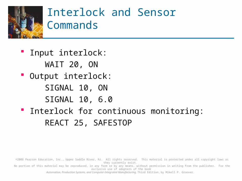
Interlock and Sensor Commands
Input interlock:
WAIT 20, ON Output interlock:
SIGNAL 10, ON
SIGNAL 10, 6.0 Interlock for continuous monitoring:
REACT 25, SAFESTOP
©2008 Pearson Education, Inc., Upper Saddle River, NJ. All rights reserved. This material is protected under all copyright laws as they currently exist. No portion of this material may be reproduced, in any form or by any means, without permission in writing from the publisher. For the exclusive use of adopters of the book
Automation, Production Systems, and Computer-Integrated Manufacturing, Third Edition, by Mikell P. Groover.
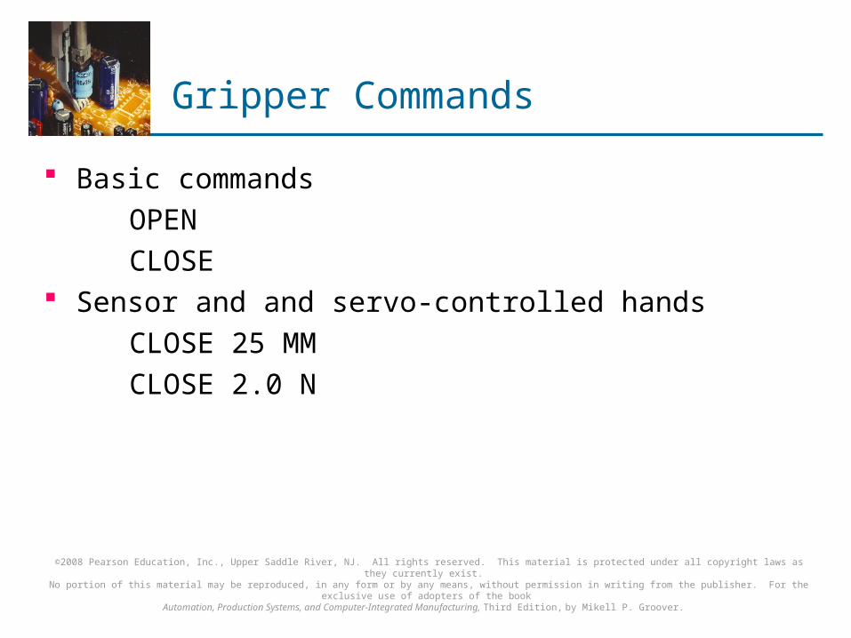
Gripper Commands
Basic commands
OPEN
CLOSE Sensor and and servo-controlled hands
CLOSE 25 MM
CLOSE 2.0 N
©2008 Pearson Education, Inc., Upper Saddle River, NJ. All rights reserved. This material is protected under all copyright laws as they currently exist. No portion of this material may be reproduced, in any form or by any means, without permission in writing from the publisher. For the exclusive use of adopters of the book
Automation, Production Systems, and Computer-Integrated Manufacturing, Third Edition, by Mikell P. Groover.
Simulation and Off-Line Programming
In conventional usage, robot programming languages still require some production time to be lost in order to define points in the workspace that are referenced in the program They therefore involve on-line/off-line programming
Advantage of true off-line programming is that the program can be prepared beforehand and downloaded to the controller with no lost production time Graphical simulation is used to construct a 3-D model
of the robot cell in which locations of the equipment in the cell have been defined previously

©2008 Pearson Education, Inc., Upper Saddle River, NJ. All rights reserved. This material is protected under all copyright laws as they currently exist. No portion of this material may be reproduced, in any form or by any means, without permission in writing from the publisher. For the exclusive use of adopters of the book
Automation, Production Systems, and Computer-Integrated Manufacturing, Third Edition, by Mikell P. Groover.
Robot Accuracy and Repeatability
Three terms used to define precision in robotics, similar to numerical control precision:
1. Control resolution - capability of robot's positioning system to divide the motion range of each joint into closely spaced points
2. Accuracy - capability to position the robot's wrist at a desired location in the work space, given the limits of the robot's control resolution
3. Repeatability - capability to position the wrist at a previously taught point in the work space