1 introduction ijser - jntuhceh...ijser international journal of scientific & engineering...
TRANSCRIPT
International Journal of Scientific & Engineering Research, Volume 6, Issue 3, March-2015 65 ISSN 2229-5518
IJSER © 2015 http://www.ijser.org
Evaluation of Curing Process for Carbon-Epoxy Composites by Mechanical Characterization for
Re-entry Vechicle Structure A. Chennakesava Reddy
Abstract— The curing of carbon/epoxy laminates has resulted the volume fraction of 71.35%. It has been found that at reliability 0.90 the survival tensile strength and flexural strength of carbon/epoxy laminates are 721.753 MPa and 557.380 MPa respectively. The occurrence of drop in flexural modulus was probably due to the fracture of the 0° fibers of the surface lamina. The void fraction is 5.49%. The interlaminar shear strength was very responsive to the presence of these gas inclusions. The fibre controlled fracture was observed in the high volume fraction of carbon fibers in the carbon/epoxy laminates.
Index Terms— Carbon fiber, epoxy, high volume fraction, inter laminar shear strength, tensile strength, flexural strength, voids.
—————————— ——————————
1 INTRODUCTION composite is a combination of of two or more distinct materials, each of which retains its own distinctive prop-erties, to create a new material. Mineral fillers, metals
and fibers have been added to polymers for decades to form composite materials. Nikbakhti and Choupani [1] in their study, the behavior of interlaminar fracture of carbon-epoxy thermoplastic laminated composite is investigated numerical-ly and experimentally. Tests are performed with Arcan speci-mens. They stated that testing with Arcan specimen gives the opportunity of utilizing just one kind of specimen for extract-ing fracture properties different mixed mode ratios of materi-als with exerting load via different load angles. He and Li [2] in their research on mechanical characterization of carbon fi-ber/epoxy compositesare used to study the consequesnces of different novolac resin loadings. The composites are prepared by solution blending and casting in a vacuum oven and the mechanical properties are investigated by means of sheart and impact tests. Paivaa, and Santos [3] have studied on degrada-tion of carbon fiber reinforced epoxy composites by ultraviolet radiation and condensation, Based on observations of physical and chemical degration it has been established that these envi-ronments operate in a synergistic manner that cuases exten-sive erosion of the epoxy matrix, resulting in a reduction in mechanical properties. Bezazi et al. [4] have studied on me-chanical properties of auxetic carbon/epoxy composites de-velopments in engineering design and technology for indus-tries such as aerospace, automobile and sports. The require-ment of such materials ranges from a combination of high stiffness and strength with significant weight savings, corro-sion resistance, chemical inertness, low maintenance and im-proved reliability. An auxetic material expands when strtched and contracts when compressed, behaving in an opposite manner compared to traditional solids.
Carbon fiber reinforced composites are usually processed
using thermoset polymers, especially epoxy resins [5], [6], [7]. Polymeric laminated composites present high strength-to-weight and stiffness-to-weight ratios when compared with metallic materials. However, these laminated composites are susceptible to damage loads because they are obtained by lay-er stacking without strong interfaces between the plies. This characteristic explains the importance of improving the dam-age tolerance of these materials, for instance, by modification of the resin system using adequate modifiers.
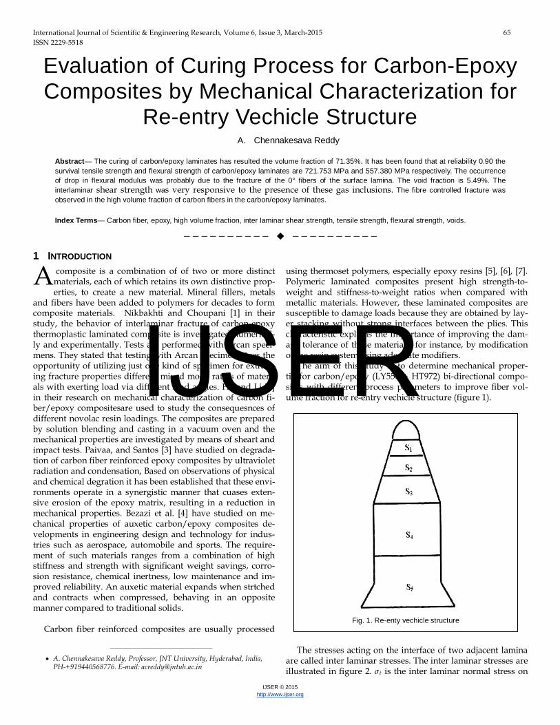
The aim of this study is to determine mechanical proper-tiesfor carbon/epoxy (LY556 + HT972) bi-directional compo-sites with different process parameters to improve fiber vol-ume fraction for re-entry vechicle structure (figure 1).
The stresses acting on the interface of two adjacent lamina
are called inter laminar stresses. The inter laminar stresses are illustrated in figure 2. σt is the inter laminar normal stress on
A
———————————————— • A. Chennakesava Reddy, Professor, JNT University, Hyderabad, India,
PH-+919440568776. E-mail: [email protected]
Fig. 1. Re-enty vechicle structure
IJSER
International Journal of Scientific & Engineering Research, Volume 6, Issue 3, March-2015 66 ISSN 2229-5518
IJSER © 2015 http://www.ijser.org
plane ABCD; τtl and τtt are the inter laminar shear stresses. These cause relative deformations between the lamina 1 and 2. If these stresses are sufficiently high, they will cause failure alon the plane ABCD. It is, therefore, of considerable interest to evaluate inter laminar shear strength through tests in which failure of laminates intiates in a shear (delamination) mode.
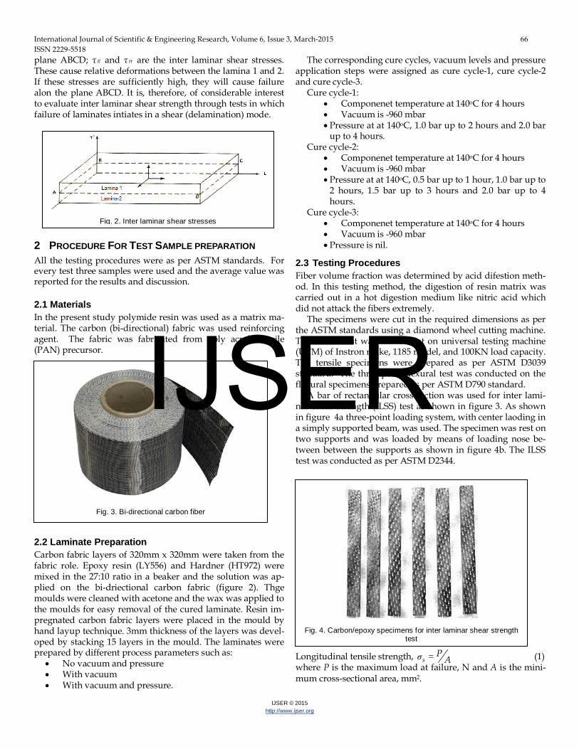
2 PROCEDURE FOR TEST SAMPLE PREPARATION All the testing procedures were as per ASTM standards. For every test three samples were used and the average value was reported for the results and discussion. 2.1 Materials In the present study polymide resin was used as a matrix ma-terial. The carbon (bi-directional) fabric was used reinforcing agent. The fabric was fabricated from poly acrylo nitrile (PAN) precursor.
2.2 Laminate Preparation Carbon fabric layers of 320mm x 320mm were taken from the fabric role. Epoxy resin (LY556) and Hardner (HT972) were mixed in the 27:10 ratio in a beaker and the solution was ap-plied on the bi-driectional carbon fabric (figure 2). Thge moulds were cleaned with acetone and the wax was applied to the moulds for easy removal of the cured laminate. Resin im-pregnated carbon fabric layers were placed in the mould by hand layup technique. 3mm thickness of the layers was devel-oped by stacking 15 layers in the mould. The laminates were prepared by different process parameters such as:
• No vacuum and pressure • With vacuum • With vacuum and pressure.
The corresponding cure cycles, vacuum levels and pressure application steps were assigned as cure cycle-1, cure cycle-2 and cure cycle-3.
Cure cycle-1: • Componenet temperature at 140oC for 4 hours • Vacuum is -960 mbar • Pressure at at 140oC, 1.0 bar up to 2 hours and 2.0 bar
up to 4 hours. Cure cycle-2:
• Componenet temperature at 140oC for 4 hours • Vacuum is -960 mbar • Pressure at at 140oC, 0.5 bar up to 1 hour, 1.0 bar up to
2 hours, 1.5 bar up to 3 hours and 2.0 bar up to 4 hours.
Cure cycle-3: • Componenet temperature at 140oC for 4 hours • Vacuum is -960 mbar • Pressure is nil.
2.3 Testing Procedures Fiber volume fraction was determined by acid difestion meth-od. In this testing method, the digestion of resin matrix was carried out in a hot digestion medium like nitric acid which did not attack the fibers extremely.
The specimens were cut in the required dimensions as per the ASTM standards using a diamond wheel cutting machine. The tensile test was carried out on universal testing machine (UTM) of Instron make, 1185 model, and 100KN load capacity. The tensile specimens were prepared as per ASTM D3039 standard. The three-point flexural test was conducted on the flexural specimens prepared as per ASTM D790 standard.
A bar of rectangular cross-section was used for inter lami-nar shear strength (ILSS) test as shown in figure 3. As shown in figure 4a three-point loading system, with center laoding in a simply supported beam, was used. The specimen was rest on two supports and was loaded by means of loading nose be-tween between the supports as shown in figure 4b. The ILSS test was conducted as per ASTM D2344.
Longitudinal tensile strength, =σsP
A (1) where P is the maximum load at failure, N and A is the mini-mum cross-sectional area, mm2.
Fig. 2. Inter laminar shear stresses
Fig. 4. Carbon/epoxy specimens for inter laminar shear strength
test
Fig. 3. Bi-directional carbon fiber
IJSER
International Journal of Scientific & Engineering Research, Volume 6, Issue 3, March-2015 67 ISSN 2229-5518
IJSER © 2015 http://www.ijser.org
Tensile modulus, Δ=tPE Ae (2)
where ∆P is the load with in elastic limit, N and e is the strain. Flexural strength, = 2
32
PLE bd (3)
where P is the maximum load at failure, N and L is the sup-port span, mm, b is the width of specimen, mm, d is the thick-ness of specimen, mm.
Flexural modulus, ( ) ( )Δ= × Δ3
34fL PE lbd (4)
where ∆P is the change in load at failure, N and ∆l is thedeflec-tion, mm.
Inter laminar shear strength, = 34
rPILSS bd (5) where Pr is the rupture load, N and L is the support span, mm, b is the width of specimen, mm, d is the thickness of specimen, mm.
3 RESULTS AND DISCUSSION The purpose of dtermination of mechanical properties like tensile, flexural and inter laminar shear strength for car-bon/epoxy (LY556 + HT972), bi-directional composites with different curing process parameters was to improve fiber vol-ume fraction for re-entry vechicle structure.
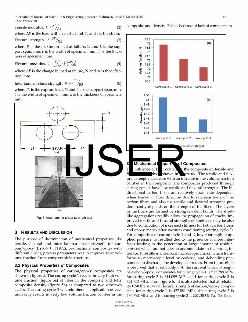
3.1 Physcial Properties of Composites The physical properties of carbon/epoxy composites are shown in figure 5. The curing cycle-1 results in very high vol-ume fraction (figure 5a) of fiber in the compiste and lofty composite density (figure 5b) as compared to two othertwo cycles. The curing cycle-3 wherein there is application of vac-uum only results in verly low volume fraction of fiber in the
composite and density. This is because of lack of compactness.
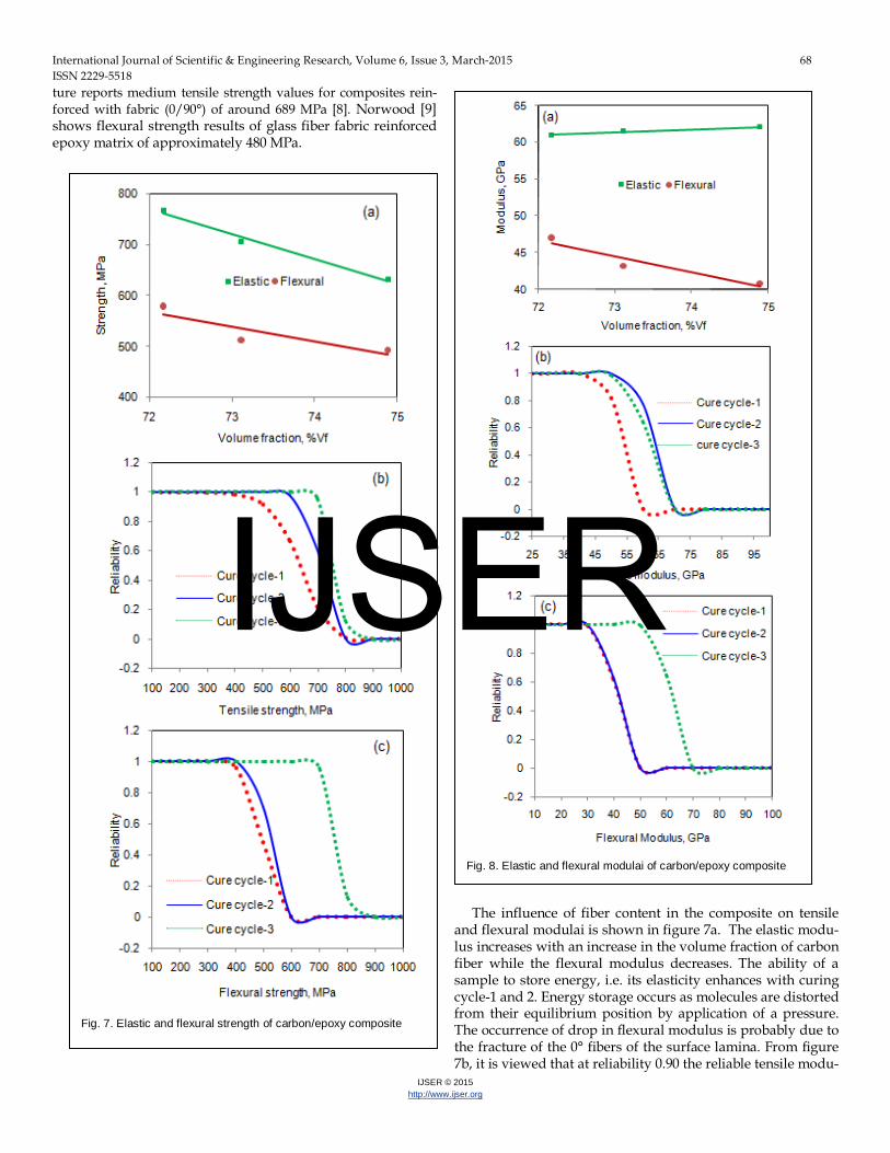
3.2 Mechancial Properties of Composites The influence of fiber content in the composite on tensile and flexural strengths is shown in figure 6a. The tensile and flex-ural strengths decrease with an increase in the volume fraction of fiber in the composite. The composites produced through curing cycle-1 have low tensile and flexural strengths. The bi-directional carbon fibers are relatively strain rate dependent when loaded in fiber direction due to rate sensitivity of the carbon fibers and also the tensile and flexural strengths pre-dominantly depends on the strength of the fibers. The layers in the fibers are formed by strong covalent bonds. The sheet-like aggregations readily allow the propagation of cracks. Im-proved tensile and flexural strengths of laminates may be also due to contribution of increased stiffness for both carbon fibers and epoxy matrix after vacuum conditioning (curing cycle-3). For composites of curing cycle-1 and -2 lower strength at ap-plied pressure is resulted due to the presence of more inter-faces leading to the generation of large amount of residual stresses which are not easy to accommodate in the strong in-terface. It results in interfacial microscopic cracks, which trans-forms to macroscopic level by coalesce, and debonding phe-nomena to discharge the developed stresses. From figure 6b, it is observed that at reliability 0.90 the survival tensile strength of carbon/epoxy composites for curing cycle-1 is 512.788 MPa, for curing cycle-2 is 644.099 MPa, and for curing cycle-3 is 721.753 MPa. From figure 6c, it is also detected that at reliabil-ity 0.90 the survival flexural strength of carbon/epoxy compo-sites for curing cycle-1 is 427.881 MPa, for curing cycle-2 is 476.792 MPa, and for curing cycle-3 is 557.380 MPa. The litera-
Fig. 5. Inter laminar shear strength test
Fig. 6. Inter laminar shear strength test
IJSER
International Journal of Scientific & Engineering Research, Volume 6, Issue 3, March-2015 68 ISSN 2229-5518
IJSER © 2015 http://www.ijser.org
ture reports medium tensile strength values for composites rein-forced with fabric (0/90°) of around 689 MPa [8]. Norwood [9] shows flexural strength results of glass fiber fabric reinforced epoxy matrix of approximately 480 MPa.
The influence of fiber content in the composite on tensile and flexural modulai is shown in figure 7a. The elastic modu-lus increases with an increase in the volume fraction of carbon fiber while the flexural modulus decreases. The ability of a sample to store energy, i.e. its elasticity enhances with curing cycle-1 and 2. Energy storage occurs as molecules are distorted from their equilibrium position by application of a pressure. The occurrence of drop in flexural modulus is probably due to the fracture of the 0° fibers of the surface lamina. From figure 7b, it is viewed that at reliability 0.90 the reliable tensile modu-
Fig. 7. Elastic and flexural strength of carbon/epoxy composite
Fig. 8. Elastic and flexural modulai of carbon/epoxy composite
IJSER
International Journal of Scientific & Engineering Research, Volume 6, Issue 3, March-2015 69 ISSN 2229-5518
IJSER © 2015 http://www.ijser.org
lus of carbon/epoxy composites for curing cycle-1 is 58.612 GPa, for curing cycle-2 is 58.356 GPa, and for curing cycle-3 is 55.892 MPa. From figure 7c, it is also noticed that at reliability 0.90 the reliable flexural strength of carbon/epoxy composites for curing cycle-1 35.556 GPa, for curing cycle-2 is 36.228 GPa, and for curing cycle-3 is 44.300 GPa. The tensile modulus of carbon fibres increases with increasing tensile strain [10]. This makes stress–strain response of carbon fibres non-Hookean. The value of coefficient of non-linear elasticity is lower in fi-bres of higher modulus and it decreases with decreasing inter-layer spacing of the fibre crystallite structure. In carbon/epoxy composite, the elastic modulus of the carbon (~228GPa) is much greater than that of the epoxy matrix (~3.5GPa) so as the volume fraction of fibres is increased, the elastic modulus of the composite (measured parallel to the fibres) increases line-arly.
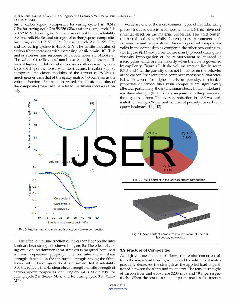
The effect of volume fraction of the carbon fiber on the inter
laminar shear strength is shown in figure 8a. The effect of cur-ing cycle on interlaminar shear strength is marginal because it is resin dependent property. The on interlaminar shear strength depends on the interfacial strength among the fabric layers only. . From figure 8b, it is observed that at reliability 0.90 the reliable interlaminar shear strengthl tensile strength of carbon/epoxy composites for curing cycle-1 is 30.203 MPa, for curing cycle-2 is 26.327 MPa, and for curing cycle-3 is 31.157 MPa.
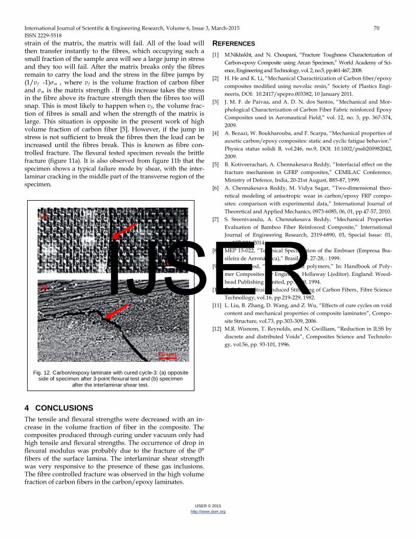
Voids are one of the most common types of manufacturing process induced defects in composite materials that have det-rimental effect on the material properties. The void content can be reduced by carefully chosen process parameters, such as pressure and temperature. The curing cycle-1 imaprts less voids in the composites as compared the other two curing cy-cles (figure 9). Macro porosities are mainly present during low viscosity impregnation of the reinforcement as opposed to micro pores which are the majority when the flow is governed by capillarity (figure 10). If the volume fraction lies between 0.5 % and 1 %, the porosity does not influence on the behavior of the carbon fiber reinforced composite mechanical character-istics. However, for higher levels of porosity, mechanical properties of carbon fiber resin composite are significantly affected, particularly the interlaminar shear. In fact, interlami-nar shear strength (ILSS) is very responsive to the presence of these gas inclusions. The average reduction in ILSS was esti-mated to average 6% per unit volume of porosity for carbon / epoxy laminates [11], [12].
3.3 Fracture of Composites At high volume fractions of fibres, the reinforcement consti-tutes the major load bearing section and the addition of matrix gradually decreases the strength as the applied load is parti-tioned between the fibres and the matrix. The tensile strengths of carbon fiber and epoxy are 3200 mpa and 70 mpa respec-tively. When the strain in the composite reaches the fracture
Fig. 9. Interlaminar shear strength of carbon/epoxy composites
Fig. 10. Void content in the carbon/epoxy composites
Fig. 11. Void content across transverse plane of the car-
bon/epoxy composite
IJSER
International Journal of Scientific & Engineering Research, Volume 6, Issue 3, March-2015 70 ISSN 2229-5518
IJSER © 2015 http://www.ijser.org
strain of the matrix, the matrix will fail. All of the load will then transfer instantly to the fibres, which occupying such a small fraction of the sample area will see a large jump in stress and they too will fail. After the matrix breaks only the fibres remain to carry the load and the stress in the fibre jumps by (1/vf -1)σm , where vf is the volume fraction of carbon fiber and σm is the matrix strength . If this increase takes the stress in the fibre above its fracture strength then the fibres too will snap. This is most likely to happen when vf, the volume frac-tion of fibres is small and when the strength of the matrix is large. This situation is opposite in the present work of high volume fraction of carbon fiber [5]. However, if the jump in stress is not sufficient to break the fibres then the load can be increased until the fibres break. This is known as fibre con-trolled fracture. The flexural tested specimen reveals the brittle fracture (figure 11a). It is also observed from figure 11b that the specimen shows a typical failure mode by shear, with the inter-laminar cracking in the middle part of the transverse region of the specimen.
4 CONCLUSIONS The tensile and flexural strengths were decreased with an in-crease in the volume fraction of fiber in the composite. The composites produced through curing under vacuum only had high tensile and flexural strengths. The occurrence of drop in flexural modulus was probably due to the fracture of the 0° fibers of the surface lamina. The interlaminar shear strength was very responsive to the presence of these gas inclusions. The fibre controlled fracture was observed in the high volume fraction of carbon fibers in the carbon/epoxy laminates.
REFERENCES [1] M.Nikbakht, and N. Choupani, “Fracture Toughness Characterization of
Carbon-epoxy Composite using Arcan Specimen,” World Academy of Sci-ence, Engineering and Technology, vol. 2, no.5, pp.461-467, 2008.
[2] H. He and K. Li, “Mechanical Charactirization of Carbon fiber/epoxy composites modified using novolac resin,” Society of Plastics Engi-neeris, DOI: 10.2417/spepro.003382, 10 January 2011.
[3] J. M. F. de Paivaa, and A. D. N. dos Santos, “Mechanical and Mor-phological Characterization of Carbon Fiber Fabric reinforced Epoxy Composites used in Aeronautical Field,” vol. 12, no. 3, pp. 367-374, 2009.
[4] A. Bezazi, W. Boukharouba, and F. Scarpa, “Mechanical properties of auxetic carbon/epoxy composites: static and cyclic fatigue behavior,” Physica status solidi B, vol.246, no.9, DOI: 10.1002/pssb200982042, 2009.
[5] B. Kotiveerachari, A. Chennakesava Reddy, “Interfacial effect on the fracture mechanism in GFRP composites,” CEMILAC Conference, Ministry of Defence, India, 20-21st August, B85-87, 1999.
[6] A. Chennakesava Reddy, M. Vidya Sagar, “Two-dimensional theo-retical modeling of anisotropic wear in carbon/epoxy FRP compo-sites: comparison with experimental data,” International Journal of Theoretical and Applied Mechanics, 0973-6085, 06, 01, pp.47-57, 2010.
[7] S. Sreenivasulu, A. Chennakesava Reddy, “Mechanical Properties Evaluation of Bamboo Fiber Reinforced Composite,” International Journal of Engineering Research, 2319-6890, 03, Special Issue: 01, pp.187-194, 2014.
[8] MEP 15-022, “Technical Specification of the Embraer (Empresa Bra-sileira de Aeronáutica),” Brasil, pp. 27-28, : 1999.
[9] L.S. Norwood, “Fibre reinforced polymers,” In: Handbook of Poly-mer Composites for Engineers. Hollaway L(editor). England: Wood-head Publishing Limited, pp. 3-69, 1994.
[10] C. P. Beetz, Strain-Induced Stiffening of Carbon Fibers, Fibre Science Technollogy, vol.16, pp.219-229, 1982.
[11] L. Liu, B. Zhang, D. Wang, and Z. Wu, “Effects of cure cycles on void content and mechanical properties of composite laminates”, Compo-site Structure, vol.73, pp.303-309, 2006.
[12] M.R. Wisnom, T. Reynolds, and N. Gwilliam, “Reduction in ILSS by discrete and distributed Voids”, Composites Science and Technolo-gy, vol.56, pp. 93-101, 1996.
Fig. 12. Carbon/expoxy laminate with cured cycle-3: (a) opposite
side of specimen after 3-point flexural test and (b) specimen after the interlaminar shear test.
IJSER