abstract index terms ijser · · 2016-09-09international journal of scientific & engineering...
TRANSCRIPT

International Journal of Scientific & Engineering Research, Volume 6, Issue 6, June-2015 1326 ISSN 2229-5518
IJSER © 2015 http://www.ijser.org
Design of Universal Test Rig and Virtual Experimentation of Hydraulic Circuit for Testing
of Line Replacement Units Narendra Rathore, M.R.Ramesh
Abstract—The proposed test rig is meant for testing of hydraulic elements used in aircraft except pump & actuators. It is used to check the performance of the hydraulic elements for pre-installation check before mounting on the aircraft. Line replacement units used in the light combat aircraft have important role to transfer pressure energy and fluid from pump to actuators. These units are used in the functioning of the flight control system and the main pump of aircraft. These are electrically operated hydraulic elements, hydraulic valves and landing gear accessories. The hydraulic pressure in the hydraulic circuit is built by the hydraulic pump, and that pressure is distributed along the pressure line with control system like line replacement units. The test rig design involved design of hydraulic circuit, selection of hydraulic elements, design of test rig which include mechanical items like test bed test stand, test chamber & hydraulic elements mounting bracket etc. The test rig will be capable of testing the various hydraulic elements on distinguish pressure and flow. There is facility to test electrically operated hydraulic elements by actuating them by means of electrical supply. It will have additional power pack which will provide hydraulic power and required work input in terms of pressure and rated flow. Also analysis is conducted on automation studio for every hydraulic circuit for pre installation check. Results have been compared with the manually calculate pressure losses and the results are presented. There is only 5-10% variation in virtual result in compare to analytically calculated results.
Index Terms— Automation studio, hydraulic circuit, light combat aircraft, line replacement units, power pack, pre installation check, universal test rig.
—————————— ——————————
1 INTRODUCTION
he universal test rig which is also known as second line test rig will be used by the second line servicing bay for conducting the pre-installation(PI) checks for the line re-
placement units(LRUs) with landing gear, flight control sys-tem and electrical LRUs which are operated by hydraulic power. The PI check-up is the sub set of the accepted test pro-cedure or production acceptance test and the pressure testing for the LRUs. The universal test rig will also have provision for delivering high pressure at lower flow rates for conducting proof pressure testing of LRUs and very high pressure at low flow rates for conducting static pressure testing of hydraulic tubes and hoses this universal test rig will also be have provi-sion of hand pump. Some of the LRUs we can directly test by the use of hand pump. And some LRUs like pressure switch, pressure transducer, charging valves etc. The hydraulic power unit and the electrical power unit will be kept in one room and other test rig will be kept in different room. The piping and cabling will be done in between the two types of the power sources. The universal test rig consist of power system will be consists of a reservoir which will supply fluid to the independent dual system operation (system A and
system B) pumps [1], [9]. It will also supply pressurised fluid to the suction side of the pump testing stand. The power sys-tem pump will supply pressurized fluid to the universal test bench system. A high pressure pump will be provided to facil-itate very high pressure to the static pressure stand for the static pressure testing of the units, tubes or hoses. The hydraulically operated units belong to LCA aircrafts which has 280 bar hydraulic pressure system. The fluid used in the hydraulic system is MIL-PRF-5606 [7]. The second line test rig broadly consists of the following units;
• Hydraulic power unit • Electrical power supply units • Test bench for the testing of hydraulic pump and elec-
tric driven pump • Facilities for mounting the LRUs • Various directional valves and proportional valves • Pressure gauge and temperature sensors
LRUs are used in the aircraft for proper flight and motion con-trol. There are many small valves, flow control valves, pres-sure control valve, direct operated or pilot operated valves used in aircraft. Apart from these, there are temperature sen-sors, pressure gauges and flow meter devices. These all type of valves and sensors are mounted in between the pressure lines. Door jacks and retraction jack assembly are used in the land-ing gear mechanism. These play important role in flying of aircraft which helps to retract the landing gear during take-off and extend gear during the landing. These line replacements units used in the power supply and flow supply for function of fly control devices like actuators.
T
———————————————— • Narendra Rathore is currently pursuing masters degree program in design
& precision engineering at National Institute of Technology, Karnataka, Surathkal,India. PH: +91-9980943483. E-mail: [email protected]
• M R Ramesh is currently working as Assistant Professor in dept of Mechan-ical Engineeering, National Institute of Technology, Karnataka, Su-rathkal,India. PH: +91-9480540801. E-mail: [email protected]
IJSER
International Journal of Scientific & Engineering Research, Volume 6, Issue 6, June-2015 1327 ISSN 2229-5518
IJSER © 2015 http://www.ijser.org
They interconnect both the hydraulic power source and fly control system of the aircraft. These are namely; rudder actua-tors for yawing movement of the aircraft, aileron for the roll-ing movement of the aircraft and elevon, for the pitching movement of the aircraft. Similarly the hydraulic pressure in the hydraulic circuit is built by the hydraulic pump, and that pressure is distributed along the pressure line with control system like LRUs. Line replacements units are the equipment which is used in between the power source pump to fly con-trol device actuators [8]. Based on working principle aircrafts LRUs hydraulic power as one of the source for its operation, they can be classified as; • Hydraulic valves and Line test LRUs • Electrical operated hydraulic LRUs • Landing gear jack accessories. Design of hydraulic circuit and installation chambers for mounting LRUs are based on requirement of tests.
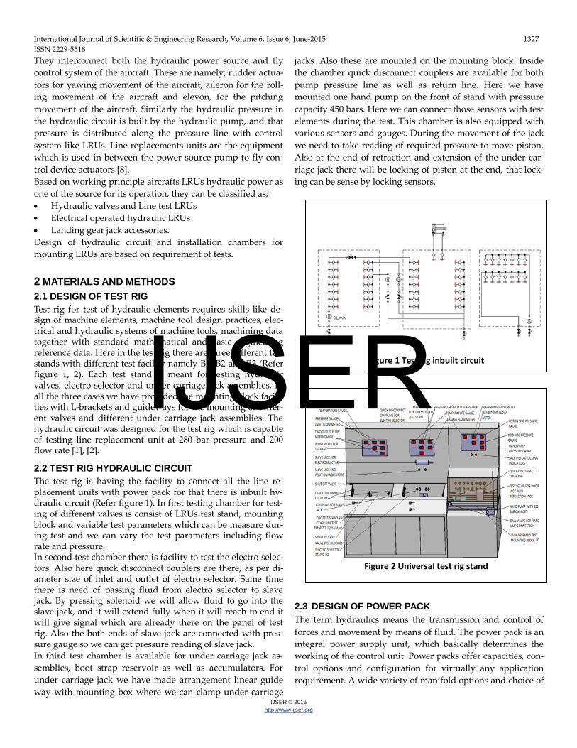
2 MATERIALS AND METHODS 2.1 DESIGN OF TEST RIG Test rig for test of hydraulic elements requires skills like de-sign of machine elements, machine tool design practices, elec-trical and hydraulic systems of machine tools, machining data together with standard mathematical and basic engineering reference data. Here in the test rig there are three different test stands with different test facility namely B1, B2 and B3 (Refer figure 1, 2). Each test stand is meant for testing hydraulic valves, electro selector and under carriage jack assemblies. In all the three cases we have provided the mounting block facili-ties with L-brackets and guideways for the mounting of differ-ent valves and different under carriage jack assemblies. The hydraulic circuit was designed for the test rig which is capable of testing line replacement unit at 280 bar pressure and 200 flow rate [1], [2].
2.2 TEST RIG HYDRAULIC CIRCUIT The test rig is having the facility to connect all the line re-placement units with power pack for that there is inbuilt hy-draulic circuit (Refer figure 1). In first testing chamber for test-ing of different valves is consist of LRUs test stand, mounting block and variable test parameters which can be measure dur-ing test and we can vary the test parameters including flow rate and pressure. In second test chamber there is facility to test the electro selec-tors. Also here quick disconnect couplers are there, as per di-ameter size of inlet and outlet of electro selector. Same time there is need of passing fluid from electro selector to slave jack. By pressing solenoid we will allow fluid to go into the slave jack, and it will extend fully when it will reach to end it will give signal which are already there on the panel of test rig. Also the both ends of slave jack are connected with pres-sure gauge so we can get pressure reading of slave jack. In third test chamber is available for under carriage jack as-semblies, boot strap reservoir as well as accumulators. For under carriage jack we have made arrangement linear guide way with mounting box where we can clamp under carriage
jacks. Also these are mounted on the mounting block. Inside the chamber quick disconnect couplers are available for both pump pressure line as well as return line. Here we have mounted one hand pump on the front of stand with pressure capacity 450 bars. Here we can connect those sensors with test elements during the test. This chamber is also equipped with various sensors and gauges. During the movement of the jack we need to take reading of required pressure to move piston. Also at the end of retraction and extension of the under car-riage jack there will be locking of piston at the end, that lock-ing can be sense by locking sensors.
2.3 DESIGN OF POWER PACK The term hydraulics means the transmission and control of forces and movement by means of fluid. The power pack is an integral power supply unit, which basically determines the working of the control unit. Power packs offer capacities, con-trol options and configuration for virtually any application requirement. A wide variety of manifold options and choice of
Figure 1 Test rig inbuilt circuit
Figure 2 Universal test rig stand
IJSER

International Journal of Scientific & Engineering Research, Volume 6, Issue 6, June-2015 1328 ISSN 2229-5518
IJSER © 2015 http://www.ijser.org
pumps enables to match any application requirement with a power pack system, at the same time ensuring cost effective operation and optimum productivity. A hydraulic power pack offers a simple method of introducing hydraulic Operation to individual machines, with flexibility of being adaptable to other duties.
It consists of an integral electrical motor, with associated tank. The pump or motor unit may be mounted on the tank or sepa-rately and packs are usually available in either horizontal or vertical configuration. Relief and check valves are normally incorporated on the tank. The basic unit may be piped to the cylinders or actuators through a suitable control valve. Hose assemblies are generally preferred to rigid piping for connect-ing the power pack to the valves and actuators manifolds. The hydraulic power packs consist of a reservoir that house the hydraulic fluid, which is the working medium. The capacity of the tank may vary accordingly to the requirements. The reser-voir is also equipped with an air breather at the top to main-tain the pressure in the tank at the atmospheric pressure and filters the oil to 40 microns (Refer figure 3 and 4) [9]. The working of a power pack commences when the pump is initialized with the help of an electric motor coupled to it. The oil is pumped from the reservoir along the suction line through a suction strainer with a capability to retain the for-eign particles up to 149 microns [9]. There is provision to measure the pressure, with the help of a pressure gauge. An isolator is used to measure the pressure immediately in any line. When the set of pressure is reached, the fluid moves to the cylinder present at the fixture (clamp). The hydraulic energy of the fluid is converted back to the me-chanical energy by the cylinder. According to the direction of the energizing of the solenoid valve, the linear movement of the clamps (clamping and unclamping) is controlled. When the solenoid valve is energized in reverse, unclamping of the work piece occurs. There is a return line provided so that the used fluid may be utilized again. Due to the friction losses,
total energy is not converted into the useful work so a part is converted into the heat. So, a heat exchanger is incorporated.
3 ANALYTICAL HEAD LOSS CALCULATION Head loss due to the frictional resistance of fluid flow within a hydraulic pipeline system is represented by any decrease in pressure. The pressure loss is determined according to the well-known Darcy Weisbach equation [5], [10]: HL = f
2Dg 𝐿V2
f = friction factor (dimensionless), L = length of pipe, D = pipe inside diameter, v = avg. fluid velocity, g = Acceleration due to gravity. The fluid flow through a pipe can be either smooth or rough, depending on flow conditions. Various factors determine the nature of flow. In principle, the flow can be stated as either laminar flow, i.e. steady, smooth flow, or turbulent flow, i.e. the flow is disturbed [6]. From a practical point of view, the Reynolds number indicates if a flow is laminar or turbulent. In the case of turbulent flow, the friction factor depends on the Reynolds number, as in the case of laminar flow as well as on the coefficient of the relative roughness – the relationship be-tween the absolute roughness of the pipe’s inner wall surface in contact with the fluid, and the diameter of the pipe (∈/𝐷), bearing in mind that the pipe can be either perform as a smooth, rough or somewhere in-between – liminal (transition-al) [5]. Several types of empirical equations that can help to deter-mine the friction factor can be found in literature. Some fairly useful ones are given below [5], [10], [3]. a) Laminar flow area at Re < 2000: f = 64 / Re b) Turbulent flow area within the smooth pipe of a hydraulic
Figure 4 Power pack hydraulic circuit
IJSER

International Journal of Scientific & Engineering Research, Volume 6, Issue 6, June-2015 1329 ISSN 2229-5518
IJSER © 2015 http://www.ijser.org
system (according to [5],[10] ) at Re > 4000: f =0.3164 / Re0.25
c) Transitional flow type area within range 2000 < Re < 4000: f = 3.9×10⁻⁶ ×Re + 0.0242 And if the flow in the circuit is turbulent that means Reynolds Number (Re)>4000 it means the fluid flow is turbulent flow, so to find the friction factor of the pipe we have to follow the Moody chart [5], [10] according to that we have to plot Re and relative roughness (∈/𝐷), and after plotting their values we will get following friction factor f [4]. Where ∈ absolute roughness and D is internal diameter of pipe.
Table1: Resistance factor 'k' for various fittings [4], [2]
Circuit element K factor
T Joint 1.8
ball Valve (wide open)
3/4 open
1/2 open
1/4 open
0.19
0.90
4.50
24.0
90˚ Elbow 0.75
45˚ Elbow 0.42
Check valve 4.0
Inline filter 10.0
Manifold 1.80
Direction valve 5.0
Entrance losses – inward
projection
1.0
Square edge inlet 0.50
Chamfered inlet 0.25
Rounded inlet 0.04 - 0.50
3.1 AUTOMATION STUDIO SIMULATION In this software we have simulated all the circuits and simul-taneously by using standard value of the real design parame-ters of the pipes and fitting we have calculated the flow and pressure results. Using the software we have calculated flow rate and the pressure for the pre installation test. These two below circuits (Refer figure 5, 6) are mainly used for the simulation of actuators and valves respectively. Based on the requirement of the pressure and flow we have designed circuit. Every test has to be carried out at standard parameters for particular line replacement units. As per the design we have used same circuit and materials for virtual experimenta-tion in automation studio. After simulation we got results of
hydraulic losses in each case. We also calculated losses manu-ally and we have compared those results here.
Similarly for pre installation of valves we have used standard flow rate and pressure for different valves. The above circuit is used for all line units and valves (Refer figure 6) [11].
4 RESULTS AND DISCUSSION Here we are comparing the pressure loss calculated manually by above given formulae and the pressure loss measured by the Automation studio. This is particularly used for the circuit simulation and analysis. The differential pressure appeared
Figure 5 PI check circuit for simulation of under car-raige jacks [11]
Figure 6 PI check circuit for imulation of valves [11]
IJSER

International Journal of Scientific & Engineering Research, Volume 6, Issue 6, June-2015 1330 ISSN 2229-5518
IJSER © 2015 http://www.ijser.org
during the various hydraulic circuit simulations. We have cal-culated the pressure loss in the circuit at different flow condi-tion for different test of the line replacement units.
4.1 HEAD LOSS CALCULATION Based on the type of line replacement units we setup the ex-perimental analysis in the automation stdio as well as analyti-cally calculation. The results are quite impressive that validate the methods of analysis used. The following head losses (Refer table 2) are results of different test hydraulic circuits for the test of particular LRU during pre installation check up.
Table 2: Comparison of hydraulic loss in different pre installa-tion test
Line re-placement Unit
Pressure loss (bar) analytically calculated
Pressure loss (bar) automation studio
Flow (LPM)
Flow syn-chronizer
2.1 1.9 40
Shuttle valve 3.6 3.0 80 Non return valve
3.5 3.1 80
Hydraulic release valve
3.6 3.0 80
Pressure re-lief valve
4.5 4 110
Nose u/c jack retraction assembly
13.6 12 148.2
Main u/c jack retraction assembly
8.5 8 48.9
Main under carriage door jack Aft
2.1 1.89 11.7
Main under carriage door jack fwd
2.2 2.1 14.4
Nose under carriage door jack
2.1 1.9 12
5 CONCLUSION This test rig is proposed for the testing of line replacement units. Based on the requirement of the pre installation check of test element we have designed test rig stand and power pack. Also designed mountings and fixtures for holding the test el-ements ie LRUs. The test rig equipped with hydraulic pipes and hoses, flow meter, shut off valve as well as quick discon-
nect couplers. For jack assemblies we have designed LM guide ways, slider and fixture and test block. The pre-installation test procedure for line replacement units also require a power pack that is capable of supplying fluid continuously with re-quired pressure and flow rate. The power pack requires a set of motors and pumps and several other components that effec-tively deliver the fluid. The components must be selected based on the power and flow rate. All the components are se-lected based on the suitable calculations and the power pack is built. In designed test rig we are successfully capable of test for all line replacement units. Using both analytical and virtual methods the head loss in every case has been calculated and being compared. The va-ration in both analytically and virtual experimental results are upo 5-10% only. Head loss in the hydraulic circuit will guide us to compensate the head loss during the pre-installation check. Automation studio does not consider the fitting losses and initial head. REFERENCES [1] Taher Salah and Saad Kassem, “Development and manu-
facture of a universal hydraulic test rig for proportional, servo valves and cylinders”, IEEE explore, 2012.
[2] Machine tool design hand book, Central Manufacturing Technology Institute, Bengaluru, Edition 2001.
[3] Robert W Fox, Alan T Mcdonald and Philip J Pritchart, Introduction to fluid mechanics, John Wiley & Sons, Inc. 8th edition.
[4] IE Idel’ Chik, Handbook of Hydraulic Resistance, 2nd edition Springer, Washington, 1986.
[5] Herbert E. Merritt, hydraulic control systems, John Wiley & Sons, Jan-1967.
[6] Vladimir Savic, “Determination of pressure losses in hy-draulic pipeline systems by considering temperature and pressure”, Journal of Mechanical Engineering, 2009.
[7] Military specification, “Test rig hydraulic system compo-nents”, USA Defence department, June1985.
[8] Hafeezur Rahman.A, SantoshP Sugate and S. Ganesan, ”Evolution of an Overhaul Methodology for a High Speed Combat Aircraft Gearbox”, IOSR-JMCE, 2015.
[9] M. Rama Narasimha Reddy, D. Sreenivasulu Reddy, P. Sundera and S. Madhusudhana, “Design of Hydraulic Power Pack for Vertical Turret Lathe” IASTER, 2014.
[10] Tudorica Daniela, “Pressure drop in the flow of oil prod-ucts through pipelines – application for hydraulic calcula-tion”, World appl. programming, Vol (4), No (5), May, 2014. pp. 140-145.
IJSER

International Journal of Scientific & Engineering Research, Volume 6, Issue 6, June-2015 1331 ISSN 2229-5518
IJSER © 2015 http://www.ijser.org
[11] Pratik Parsania and Jagdish Dave, “Design of Hydraulic Power pack for SPM”, June 2013.
IJSER