1 introduction - witpress.com · the popularity of the fdm (e.g., phoenics) ... must be done in...
TRANSCRIPT

Computational fluid dynamics simulations of the
human lung: an overview
T. Martonen,* D. Hwang,** X. Guan,' J. Fleming*
"Experimental Toxicology Division, National Health and
Environmental Effects Research Laboratory, U.S. Environmental
Protection Agency, Research Triangle Park, NC 27711, USA
*>MCNC-North Carolina Supercomputing Center, Research
rn g/ef6zr 7VC 27770, C%4
Center for Extrapolation Modeling, Duke University, Durham, NC
27770, (7&4
^Department of Medicine, Southampton General Hospital,
SOP
Abstract
Mathematical models describing the behavior and fate of inhaled particles haveimportant applications to inhalation toxicology and aerosol therapy. Since parti-cles are entrained and transported by inhaled air, their trajectories will be affectedby the very nature of an air stream which, in turn, will be affected by the actualmorphology of the lung. A mathematical model which calculates the depositionpatterns of inhaled particles has been presented. Future models will naturallydepend on the quality and quantity of morphological data available as inputfor supercomputer algorithms describing human airways. To develop advancedmodels, we are performing experimental studies using fiberoptic bronchoscopy toobtain data with heretofore unavailable resolution of airway morphology. Herein,we provide an overview of key components of a research program which is aninternational, multidisciplinary collaboration. A key question that we shall raiseis: will the character of the input data available to describe airway structuresdictate whether a modeler should employ the finite difference method (FDM),the finite element method (FEM) or the boundary element method (BEM) tosimulate airflow within the lung?
Transactions on Biomedicine and Health vol 3, © 1996 WIT Press, www.witpress.com, ISSN 1743-3525

70 Simulation Modelling in Bioengineering
1 Introduction
Mathematical models describing the behavior and fate of inhaled particleshave important applications to the subjects of inhalation toxicology andaerosol therapy. Regarding inhalation toxicology the models are used forthe risk assessment of air pollutants, specifically to predict the dosage oftoxic substances delivered to airway cells. Regarding aerosol therapy themodels are used to administer aerosolized pharmaceuticals, specifically totarget drug particles to appropriate sites within human lungs and therebyelicit optimum therapeutic effects.
Since particles are entrained and transported by inhaled air, their tra-jectories will be affected by the very nature of an airstream which, in turn,will be affected by the actual morphology of the lung. That is, particlemotion will be influenced by factors such as: is the air flow laminar orturbulent? And, if flow is laminar, is the corresponding velocity profile adeveloping one or is it fully developed (i.e., parabolic)? Moreover, the mo-tion of air is itself affected by two factors: (a) the ventilatory parameters ofhuman subjects such as tidal volume (the volume inspired per breath, ml)and respiratory frequency (rate of ventilation, breaths/min), and (b) thestructure of the lung through it is flowing. Regarding (a), the level of respi-ratory intensity (e.g., sedentary or excercise) controls the volumetric intakeof air and, therefore, velocities within individual airways. Regarding (b), ona large scale, the branching network affects flow, for instance, by creatingsecondary currents (e.g., double vortices) within individual airways. On asmall scale, the surface irregularities of airways, for example, cartilaginousrings, produce distinctive flow patterns. The interactive effects outlined inthe preceding paragraph are extremely complicated but predictable.
A mathematical model which calculates the deposition patterns of in-haled particles has been presented (Martonen [1]; Martonen and Katz [2-4];Martonen et al. [5]). To develop advanced models, we are performing ex-perimental studies to obtain data with heretofore unavailable resolution ofairway morphology using fiberoptic bronchoscopy and particle distributionusing SPECT (Single Photon Emission Computer Tomography). The typeof mathematical models which we will develop will naturally depend on thequality and quantity of morphological data available to use as input forsupercomputer algorithms describing human airways. Indeed, that is thetheme of this text: will the character of the input data available to describeairway structures dictate whether a modeler should employ the finite dif-ference method (FDM), the finite element method (FEM) or the boundaryelement method (BEM) to simulate airflow within the lung? Herein, weshall provide an overview of key components of the research program whichis an international, multidisciplinary collaboration.
Transactions on Biomedicine and Health vol 3, © 1996 WIT Press, www.witpress.com, ISSN 1743-3525

Simulation Modelling in Bioengineering 71
2 Methods
2.1 Airway Morphology
The most frequently used descriptions of the human lung are those fromthe laboratories of Weibel [6] and Horsfield [7], Herein, we shall adoptthe former. It is a symmetric, dichotomously branching system which isdivided into 23 generations, i, of airways. The trachea is generation i = 0and the alveolar sacs are generation are i = 23. There are T number ofairways in each generation. The lung is separated into two compartmentsaccording to structure and function. The muscle-lined, conducting passagesof the tracheobronchial (TB) compartment are airways 0 < i < 16. Thealveolated, gas exchange passages of the pulmonary (P) compartment areairways 17 < i < 23.
A unique feature of our research program is the performance of clinicalinvestigations which map the interiors of human airways using fiberopticbronchoscopy. We have identified factors, such as cartilaginous rings andcarinal ridges, which have pronounced effects on localized flow patternswithin human lungs.
2.2 Supercomputer Codes
We have used a systematic approach to define a mathematical descriptionof the morphology of the human lung suitable for integration with advancedclinical protocols. Our approach is outlined below using the Cray T90 su-percomputer.
(1) Original algorithms were written to describe the larynx, cartilagi-nous rings and carinal ridges (Martonen et al. [8-11]).
(2). We used Voronoi diagrams and Delaunay tessellation to formulatethe outer surfaces of whole lungs (Martonen et al. [12]).
(3). Original algorithms were written to map networks within humanlungs (Martonen et al. [13]).
(4). Original algorithms were written to divide human lungs into con-centric layers, or shells (Martonen et al. [14]); see Figure 1.
The intent of steps (1-4) is to describe the lung in a manner conducivefor the comparison of theoretical and experimental particle deposition pat-terns. In our research program, the deposition patterns of inhaled radio-labelled particles are measured (see Figure 2) in human test subjects usinga shell format (Fleming et al. [15, 16]).
2.3 Fluid Dynamics
In our investigation, different techniques of numerical analysis have beenemployed. For example, PHOENICS was used to study the larynx and
Transactions on Biomedicine and Health vol 3, © 1996 WIT Press, www.witpress.com, ISSN 1743-3525
72 Simulation Modelling in Bioengineering
FIDAP was used for the lung per se. PHOENICS uses the finite volumemethod (FVM) whereas FIDAP employs FEM. The FVM is a scheme of thegeneral FDM. The FDM is conceptually different from another technique ofnumerical analysis, FEM. The FDM discretizes the governing equations atprescribed grid points whereas FEM discretizes the domain of the problemand uses approximations (e.g., linear) to approach the real solution. Fordetails see Section 3.
2.4 Deposition Model
A mathematical model which calculates the deposition patterns of inhaledparticles has been developed by Martonen [1]. In a series of manuscripts themodel has been validated by data from experiments conducted with healthytest subjects and patients with respiratory diseases (Martonen and Katz [2-4]) and Martonen et al. [5]. The experimental data measured deposition inthe whole lung, and the respective TB and P compartments.
To advance particle deposition modeling for aerosol therapy and in-halation toxicology applications, we are now performing experimental stud-ies to obtain data of heretofore unavailable resolution regarding the spatialdiscrimination of particle distribution inside the lung. Using SPECT, thelung will be divided into small 3D units termed voxels.
The type of mathematical models which we shall develop (i.e., FDM,FEM or BEM) will naturally depend on the quality and quantity of mor-phological data available to use as input for supercomputer algorithms de-scribing human airways. For illustration, let us consider two kinds of clinicalexaminations: a gas perfusion test yields overall data on the exterior shapeof the whole lung (i.e., the enveloping form of the i = 23 airways), andfiberoptic bronchoscopy yields data on the interiors of individual airways.Therefore, each technique has inherent limitations: a gas perfusion testlacks the resolution necessary to provide information on individual airways,and due to size constraints a fiberoptic bronchoscope can only penetrate toabout the i = 6 level of airways. So, at the very least the problem is this:how can a modeler simulate airways between generations 7 < i < 22?
The above point establishes the theme of this text. Namely, will thecharacter (i.e., quality and quantity) of the input data available to describeairway structures dictate whether a modeler should employ FDM, FEM orBEM to simulate airflow within the lung?
3 Comparison of numerical analysis techniques for airflow simulations
The motion of an incompressible Newtonian viscous fluid is governed by theNavier-Stokes equations which in cylindrical coordinates are:
Transactions on Biomedicine and Health vol 3, © 1996 WIT Press, www.witpress.com, ISSN 1743-3525
Simulation Modelling in Bioengineering 73
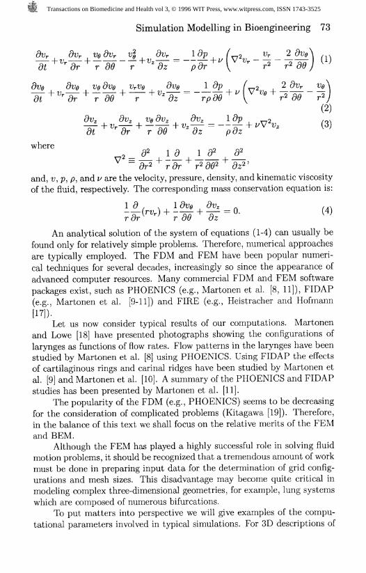
dt ^ dr r 80 r * dz pdr \ *" r* r* 86)
dt """ "' dr r 60'* r * "* dz rpdO*" ( "° * r* 89 r*(2)
UUz VUz U0 uuz VL/Z J- L/y 2 /ONh Vr 1 r Vz = — h V V Vz \3)
dt dr r 80 dz pdz
where 2y2 ^ 1 1 1 ^
and, v, p, p, and v are the velocity, pressure, density, and kinematic viscosityof the fluid, respectively. The corresponding mass conservation equation is:
19, 1 &;<, <9tr, / .x(rVr) H 1 — U. ^4j
r dr r d9 dz
An analytical solution of the system of equations (1-4) can usually befound only for relatively simple problems. Therefore, numerical approachesare typically employed. The FDM and FEM have been popular numeri-cal techniques for several decades, increasingly so since the appearance ofadvanced computer resources. Many commercial FDM and FEM softwarepackages exist, such as PHOENICS (e.g., Martonen et al. [8, 11]), FIDAP(e.g., Martonen et al. [9-11]) and FIRE (e.g., Heistracher and Hofmann
[17]).Let us now consider typical results of our computations. Martonen
and Lowe [18] have presented photographs showing the configurations oflarynges as functions of flow rates. Flow patterns in the larynges have beenstudied by Martonen et al. [8] using PHOENICS. Using FIDAP the effectsof cartilaginous rings and carinal ridges have been studied by Martonen etal. [9] and Martonen et al. [10]. A summary of the PHOENICS and FIDAPstudies has been presented by Martonen et al. [11].
The popularity of the FDM (e.g., PHOENICS) seems to be decreasingfor the consideration of complicated problems (Kitagawa [19]). Therefore,in the balance of this text we shall focus on the relative merits of the FEMand BEM.
Although the FEM has played a highly successful role in solving fluidmotion problems, it should be recognized that a tremendous amount of workmust be done in preparing input data for the determination of grid config-urations and mesh sizes. This disadvantage may become quite critical inmodeling complex three-dimensional geometries, for example, lung systemswhich are composed of numerous bifurcations.
To put matters into perspective we will give examples of the compu-tational parameters involved in typical simulations. For 3D descriptions of
Transactions on Biomedicine and Health vol 3, © 1996 WIT Press, www.witpress.com, ISSN 1743-3525
74 Simulation Modelling in Bioengineering
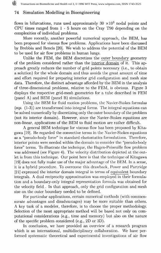
flows in bifurcations, runs used approximately 30 xlO^ nodal points andCPU times ranged from 1-5 hours on the Cray T90 depending on thecomplexities of individual problems.
More recently, another powerful numerical approach, the BEM, hasbeen proposed for viscous flow problems. Applications have been discussedby Brebbia and Rencis [20]. We wish to address the potential of the BEMto be used for air flow problems in human lungs.
Unlike the FEM, the BEM discretizes the outer boundary geometryof the problem considered rather than the interior domain of it. This ap-proach greatly reduces the number of grid points necessary (i.e., to obtaina solution) for the whole domain and thus avoids the great amount of timeand effort required for preparing interior grid configuration and mesh sizedata. Therefore, the distinct advantage afforded by the BEM in the analysisof three-dimensional problems, relative to the FEM, is obvious. Figure 3displays the respective grid-mesh geometries for a tube described in FEM(panel A) and BEM (panel B) simulations.
Using the BEM for fluid motion problems, the Navier-Stokes formulas(eqs. (1-3)) are transformed into integral forms. The integral equations canbe solved numerically by discretizing only the outer boundary of the problem(not its interior domain). However, since the Navier-Stokes equations arenon-linear, applications of the BEM to fluid motion are rather difficult.
A general BEM technique for viscous flow has been proposed by Kita-gawa [19]. He regarded the convective terms in the Navier-Stokes equationsas a "pseudo-body force" in standard elastostatics formulations. Therefore,interior points were needed within the domain to consider the "pseudo-bodyforce" terms. To illustrate the technique, the Hagen-Poiseuille flow problemwas addressed (see Figure 4). The velocity distribution depicted at the out-let is from this technique. Our point here is that the technique of Kitagawa[19] does not fully make use of the major advantage of the BEM. In a sense,it is a hybrid procedure. To overcome this drawback, Power and Partridge[21] expressed the interior domain integral in terms of equivalent boundaryintegrals. A dual reciprocity approximation was employed in their formula-tion and a boundary-only integral representation formula was obtained forthe velocity field . In that approach, only the grid configuration and meshsize on the outer boundary needed to be defined.
For particular applications, certain numerical methods (with commen-surate advantages and disadvantages) may be more suitable than others.A key task of a modeler, therefore, is to choose the proper methodology.Selection of the most appropriate method will be based not only on com-putational considerations (e.g., time and memory) but also on the natureof the specific problem considered (e.g., 2D or 3D).
In conclusion, we have provided an overview of a research programwhich is an international, multidisciplinary collaboration. We have per-formed systematic theoretical and experimental investigations of air flow
Transactions on Biomedicine and Health vol 3, © 1996 WIT Press, www.witpress.com, ISSN 1743-3525

Simulation Modelling in Bioengineering 75
patterns in human lungs. The type of future mathematical models (forinstance, FDM, FEM or BEM) will naturally depend on the quality andquantity of morphological data available to use as input for supercomputer
algorithms describing human airways.
Disclaimer: This manuscript has been reviewed in accordance with the policy of theNational Health and Environmental Effects Research Laboratory, U.S. EnvironmentalProtection Agency, and approved for publication. Approval does not signify that thecontents necessarily reflect the views and policies of the agency, nor does mention oftrade names or commercial products constitute endorsement or recommendation for use.
Key Words: fluid dynamics, numerical methods, human lung.
References
1. Martonen, T. B. Mathematical model for the selective depositionof inhaled pharmaceuticals, J Pharm Sci, 1993, 82, 1191.
2. Martonen, T. B. & Katz, I. Deposition patterns of aerosolizeddrugs within human lungs: Effects of ventilatory parameters,P/wrm Aea, 1993, 10, 871.
3. Martonen, T. B. & Katz, I. Deposition patterns of polydisperseaerosols within human lungs, J Aerosol Med, 1993, 6, 251.
4. Martonen T. B. & Katz, I. Inter-related effects of morphologyand ventilation on drug deposition patterns, S.T.P., Pharm Sci,
1994, 4, 11.
5. Martonen, T. B., Katz, I. & Cress W. Aerosol deposition as afunction of airway disease: cystic fibrosis, Pharm Res, 1995, 12,95.
6. Weibel, E. R. Design of airways and blood vessels as branchingtrees. In: The Lung: Scientific Foundations] (ed R.G. Crystal,J.B. West, P.J. Barnes, N.S. Cherniack & .E.R. Weibel), Vol. 1,Raven Press, New York, 1991, 711.
7. Horsfield, K. Pulmonary airways and blood vessels considered asconfluent trees. In: The Lung: Scientific Foundations', (ed R.G.Crystal, J.B. West, P.J. Barnes, N.S. Cherniack & .E.R. Weibel),Vol. 1, Raven Press, New York, , 1991, 721.
8. Martonen, T. B., Zhang, Z. & Lessmann, R. C. Fluid dynamicsof the human larynx and upper tracheobronchial airways, Aerosolgcz 7ecA, 1993, 19, 133-156.
9. Martonen, T. B., Yang, Y. & Xue, Z. Q. Influences of cartilagi-nous rings on tracheobronchial fluid dynamics, Inhal Tox, 1994,6, 185-203,
Transactions on Biomedicine and Health vol 3, © 1996 WIT Press, www.witpress.com, ISSN 1743-3525

76 Simulation Modelling in Bioengineering
10. Martonen, T. B., Yang, Y. & Xue, Z. Q. Effects of carinal ridgeshapes on lung airstreams, Aerosol Sci Tech, 1994, 21, 119-136.
11. Martonen, T. B., Yang, Y., Xue, Z. Q. & Zhang, Z. Motion of airwithin the human tracheobronchial tree, Partic Sci Tech, 1994,12, 175-188.
12. Martonen, T. B., Yang, Y., Hwang, D. & Fleming, J. S. Mappingthe human lung using Delaunay tessellation, J Comp Biomed Res,1994, 27, 245.
13. Martonen, T. B., Yang, Y., Hwang, D. & Fleming, J. S. Computersimulations of human lung structures for medical applications,Comp Bio Med, 1995, 25, 431.
14. Martonen, T. B., Yang, Y., Hwang, D. & Fleming, J. S. Com-puter model of human lung morphology to complement SPECTanalyses, Int J Bio-Med Comp, 1995, 40, 5.
15. Fleming, J. S., Nassim, M., Hashish, A. H., Bailey, A. G., Con-way, J., Holgate, S., Halson, P., Moore, E. & Martonen, T. B.Description of pulmonary deposition of radiolabeled aerosol byairway generation using a conceptual three dimensional model oflung morphology, J Aerosol Med, 1995, 8, 341-355.
16. Fleming, J., Halson, P., Conway, J., Moore, E., Nassim, A., Bailey,A., Holgate, T. & Martonen, T. Three dimensional descriptionof pulmonary deposition of inhaled aerosol using data from multi-modality imaging, J Nuclear Med, (in press).
17. Heistracher, T. & Hofmann, W. Physiologically realistic modelsof bronchial airway bifurcations, J. Aerosol Sci, 1995, 26, 497-509.
18. Martonen, T. B. & Lowe, J. Assessment of aerosol depositionpatterns in human respiratory tract casts, Chapter 13, Aerosolsin the Mining and Industrial Work Environments, ed V. A. Marple& B. Y. H. Liu, Vol. 1, pp. 151-164, Ann Arbor Science, 1983.
19. Kitagawa, K. Boundary Element Analysis of Viscous Flow,Springer-Verlag, 1990.
20. Brebbia, C. A. (ed) & Rencis, J. J. (ed). Boundary Elements XV:Fluid Flow and Computational Aspects, Proc Int Conf BoundaryElem Meth, Computational Mechanics Publ, Southampton, Engl,1993.
21. Power, H. & Partridge, P. W. Use of Stokes' fundamental so-lution for the boundary only element formulation of the three-dimentional Navier-Stokes equations for moderate Reynolds num-bers, Int J Numer Meth Engr, 1994, 37, 1825-1840.
Transactions on Biomedicine and Health vol 3, © 1996 WIT Press, www.witpress.com, ISSN 1743-3525

Simulation Modelling in Bioengineering 77
Figure 1: Supercomputer-generated display of the human lung divided intoten shells to correspond to SPECT analyses.
Shell I .. 7 0 9 10
Shell I .. 0 9
Figure 2: SPECT transformation of a human lung into hemispherical shells(adapted from Fleming et al. [15]).
Transactions on Biomedicine and Health vol 3, © 1996 WIT Press, www.witpress.com, ISSN 1743-3525

Interior points for "pseudo-body force" term
(A)
Mesh on boundary(B)
Figure 3: Description of a tube used in flow analyses: (A) FEM grid configuration and mesh size for a generation i = 11airway, (B) BEM grid configuration and mesh size (adapted from Kitagawa [19]).
No slip Boundary Condition
Vx=1Vy = 0
00
Cfl3
OPuCD
td5"(D203.g(D
(A) (B)
Figure 4: Simulation of 2D flow in the tube of Figure 3: (A) FEM, velocity vector field from FIDAP for sedentary activity(tidal volume = 500 ml, frequency = 14 breaths/min), (B) BEM, velocity distribution at inlet (adapted from Kitagawa [19]).
Transactions on Biomedicine and Health vol 3, © 1996 WIT Press, www.witpress.com, ISSN 1743-3525