1. new brx remote base controllers: bx-dmio, bx-ebc100 ... · h. project: if writing a project to...
TRANSCRIPT

Do-more Updates Rel 2.3, June 6, 2018
Page 1 of 57
This file documents the list of new features, enhancements, and “adjusted anomalies”, starting with the most recent Rel 2.3 version, followed by the 2.2 version, 2.1.x versions, and finishing with Rel 2.0 version (there is a link at the end that documents all of the Rel 1.x update details). Each page’s header shows the version for that current page.
1. New BRX Remote Base Controllers: BX-DMIO, BX-EBC100, and BX-MBIO
Each can support up to 8 BX I/O modules, so with the new 32 point BX I/O modules (see #2
below), each remote base can support up to 256 I/O points. One PLC can master up 16 of these
remote bases, so one PLC can add an another 4096 BRX I/O points to its local I/O.
Requires Do-more Technology Version 2.3 (DmT 2.3); see PLC->Update Firmware.
Do-more Updates Rel 2.3, June 6, 2018
Page 2 of 57
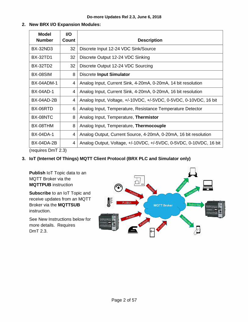
2. New BRX I/O Expansion Modules:
Model
Number
I/O
Count Description
BX-32ND3 32 Discrete Input 12-24 VDC Sink/Source
BX-32TD1 32 Discrete Output 12-24 VDC Sinking
BX-32TD2 32 Discrete Output 12-24 VDC Sourcing
BX-08SIM 8 Discrete Input Simulator
BX-04ADM-1 4 Analog Input, Current Sink, 4-20mA, 0-20mA, 14 bit resolution
BX-04AD-1 4 Analog Input, Current Sink, 4-20mA, 0-20mA, 16 bit resolution
BX-04AD-2B 4 Analog Input, Voltage, +/-10VDC, +/-5VDC, 0-5VDC, 0-10VDC, 16 bit
BX-06RTD 6 Analog Input, Temperature, Resistance Temperature Detector
BX-08NTC 8 Analog Input, Temperature, Thermistor
BX-08THM 8 Analog Input, Temperature, Thermocouple
BX-04DA-1 4 Analog Output, Current Source, 4-20mA, 0-20mA, 16 bit resolution
BX-04DA-2B 4 Analog Output, Voltage, +/-10VDC, +/-5VDC, 0-5VDC, 0-10VDC, 16 bit
(requires DmT 2.3)
3. IoT (Internet Of Things) MQTT Client Protocol (BRX PLC and Simulator only)
Publish IoT Topic data to an
MQTT Broker via the
MQTTPUB instruction
Subscribe to an IoT Topic and
receive updates from an MQTT
Broker via the MQTTSUB
instruction.
See New Instructions below for
more details. Requires
DmT 2.3.

Do-more Updates Rel 2.3, June 6, 2018
Page 3 of 57
4. New Instructions
a. MQTTPUB - IoT Publish MQTT Topics (Protocol – Standard)
The MQTTPUB instruction
can publish payloads of
multiple topics at a desired
time interval, or on an
event-based edge trigger, to
the MQTT Broker defined in
your MQTT Client Device.
Each Topic’s published
Payload (data) can be set in
a STRING buffer as text or
as raw bytes (see
STRPRINT).
The Last Will & Testament
(LWT) is set up in the
MQTT Client Device. The
LWT Topic or Payload can
be changed via the
DEVWRITE instruction.
b. MQTTSUB – IoT Subscribe MQTT Topics (Protocol – Standard)
The MQTTSUB instruction
can subscribe to multiple
Topics sourced by the
MQTT Broker defined in
your MQTT Client Device.
As long as instruction has
power-flow, each Topic will
receive fresh data Payload
as the MQTT Broker
publishes it. The Payload is
written as a STRING data
buffer. The contents of the
STRING can then be
processed in various ways
based on the format of that
specific Topic’s Payload
(see STR2INT, STR2REAL,
STRGETB, etc.).
The two new MQTT Publish/Subscribe instructions support detailed transaction logging using
DmLogger when you turn on ST36 $EnableMsgDump status bit.

Do-more Updates Rel 2.3, June 6, 2018
Page 4 of 57
5. Enhancements
a. Ladder View: MEMCOPY warns when copying raw bytes from/to structures to/from numeric
data blocks, especially STRINGs (5979).
b. Ladder View: INI – Immediate Input instruction editor smarter based on the BRX model’s local
discrete input count.
c. Ladder View: DEVREAD and DEVWRITE instructions support the new MQTT Client device
configuration parameters: Authentication Account User Name and Password, LW&T Topic
and Payload, Server IP Address Name Port and Timeout.
d. Memory View: Status can be turned OFF (5316).
e. System Configuration Dialog: Added right-click context menu to Memory Configuration’s Edit
User Data Type Definition dialog to Add/Insert/Edit/Delete/… Fields in the UDT, and to the
Memory Configuration’s User Data Type (UDT) tab to Add/Edit/Delete/… UDTs (6029, thanks
to JW).
f. Motion: Improved Axis Instructions’ handling of Axis Devices and other related Axis
parameters (5983).
g. Security: After the Administrator logs in, report the number of Failed Logins if any have
occurred (this is maintained in DST386/$FailedLoginCnt). Also, give the Administrator the
option to reset it (5101).
h. Project: If writing a Project to the PLC requires a mode change from Program to Run, and the
new Project creates an issue where the PLC could not return to Run mode, give the user
options to make changes to their Project’s System Configuration, a probable place to
correct any issues (4776).
i. Project Files: Generates Project and C-more export files automatically whenever you Save a
Project to Disk. These export files are also maintained as part of the Auto-Save and Backup
facilities. The names of these export files are based on the project file name, and are created in
the same folder as the project file. For example, if your project file was called MyProject.dmd,
then the following 2 files will be generated whever you save MyProject.dmd to disk:
MyProject_EXPORT_DMD.txt and MyProject_EXPORT_CMORE.txt (5978).
j. Modbus/TCP: Latest firmware for all EBC100 models (H2, T1H, and BX), GSEDRV100,
BX-MBIO, and all ECOM100 models (H2 and H0) lets you close Modbus/TCP Port 502, but
lets you configure other TCP ports for Modbus/TCP. Requires NetEdit version 3.16, which
ships with Designer 2.3.
k. Live Update: At end of Live Update of firmware, which downloads the latest and greatest
firmware files from our web server, prompt the user to update the firmware in any of their
hardware (5272).

Do-more Updates Rel 2.3, June 6, 2018
Page 5 of 57
6. Adjusted Anomalies
a. Dashboard: When reporting the SMTP Server’s address, report the Name instead of the IP
Address if that is how it is configured.
b. System Configuration: Properly handling multi-packet server credential verification for SMTP
Client configuration.
c. Ladder View: Status for DRUM instruction’s Mask Element Name text displays correctly.
Note: The STATUS display was always correct. What was corrected was the text for the
Element Name (since the applied Mask element is indexed based on the step number, e.g.
D100 when on step 1, D101 when on step 2, etc.) (6040).
d. Ladder View: Properly displays word-wrapped script instructions as their width changes due to
the width of other instructions in the output column (6055).
e. Ladder View: When opening up a project file, properly handle when there are differences
between the default zoom level vs. the workspace’s zoom level of a specific view.
f. Ladder View: Paste of AXCAM properly displays when the device parameter is an unassigned
nickname (6057).
g. Trend View/PID View Snapshot window properly displaying values to the configured number of
decimal places (6054).
h. Output Window: Paste Instruction properly maintains messages logged to the Output Window
(5929).

Do-more Updates Rel 2.2 March 15, 2018
Page 6 of 57
Changes in Do-more 2.2
1. Do-more Designer and its HAPTools now install to the standard Window’s Program Files folder,
instead of off the system root folder. The Projects folder is now located within the Designer 2.2
folder below your PC’s Public\Documents folder (or All User\Documents in older Windows
versions). Look for the Do-more\Designer2_2\... subfolder hierarchy below those two
different system folder locations. See Open Designer 2.2 Folder from Launchpad view in
Enhancements section below.
2. Added support for the new DURApulse GS4 Drives (minimally requires Do-more Technology
Version 2.2 (DmT 2.2), see PLC->Update Firmware). Along with a GS-EDRV100 interface module,
GS4 Series drives can be part of your Do-more PLC’s Ethernet I/O network, just like how the GS1,
GS2, and GS3 drives work as Ethernet I/O slaves. GSREGRD and GSREGWR instructions
support the new GS4’s parameter set. Note: the GS-EDRV100 firmware must be at least 6.0 to
support the GS4 (use NetEdit to upgrade your GS-EDRV100 module).
3. EMAIL enhancements
a. DNS support lets you specify the URL name of your SMTP server (e.g. smtp.gmail.com). The
Do-more PLC will resolve that name automagically whenever it sends out an email (requires
DmT 2.2). See how to configure your DNS Server Address in Enhancements section below.
b. Secure EMAIL on BRX
As security becomes more
important, the BRX PLCs added
support for Transport Layer
Security (TLS) when sending email.
In addition, BRX PLCs support
Certificate Validation to ensure the
identity of the remote server.
You can also verify your SMTP
Client settings against the actual
SMTP Server from your PC.
Secure EMAIL is optional, but
requires DmT 2.2 on your BRX
PLC if configured. Also requires
BRX Gate Array version 1.8.

Do-more Updates Rel 2.2 March 15, 2018
Page 7 of 57
4. New Instructions
a. INI – Immediate Discrete Input (only available on BRX MPUs with onboard discrete inputs)
Along with OUTI/SETI/RSETI that can generate clock pulse trains, use INI to read back data
from devices that return data based on the generated clock pulse train.
Note: INI instruction is NOT needed by ISR Interrupt Service Routines since ISRs
automagically reads ALL the High Speed I/O input states upon entry to the ISR. Also, this
instruction does NOT update the image register value of the Specific Discrete Input parameter
(e.g. X0). It just gets the ON/OFF state of the physical input of the Specific Discrete Input
parameter and writes that state to the Discrete Result parameter. This way the Specific
Discrete Input image register value remains invariant throughout that specific PLC logic scan.
5. New System Status Elements:
DST52
DST58
$ActiveSessions
$ProgramChecksum
see Help Topic DMD0208
System Nickname Locations
6. Enhancements
a. There is a link to Open Designer 2.2 Folder in the Applications panel of the Launchpad view to
open Windows Explorer to the Designer 2.2 folder below your PC’s Public Documents system
folder:
There is a similar link to Open HAPTools Folder further down the Applications list. If you have
an older version of Windows, these will be located below the All Users Documents folder.
b. Added Close button [x] to every MDI View tab (5972).
Do-more Updates Rel 2.2 March 15, 2018
Page 8 of 57
c. View Options Dialog: Smarter about when to automatically check the Apply to New Views
checkbox (5853).
d. Ladder View: Added option to Always start in Edit Mode (5620).
e. Ladder View: Show specific Leg Label or Edge Trigger tooltip when floating mouse cursor
over an instruction’s Leg Label or Edge trigger. Tooltip includes a link to the instruction’s Help
topic to get more details about the input leg (5206).
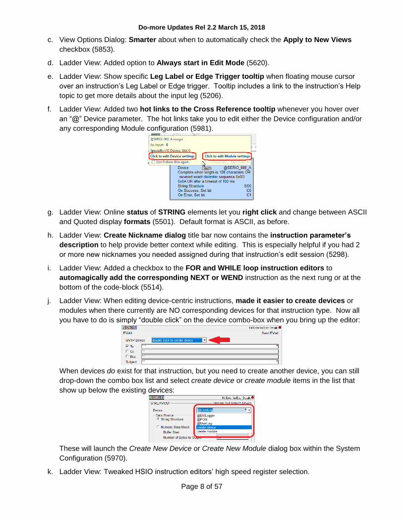
f. Ladder View: Added two hot links to the Cross Reference tooltip whenever you hover over
an “@” Device parameter. The hot links take you to edit either the Device configuration and/or
any corresponding Module configuration (5981).
g. Ladder View: Online status of STRING elements let you right click and change between ASCII
and Quoted display formats (5501). Default format is ASCII, as before.
h. Ladder View: Create Nickname dialog title bar now contains the instruction parameter’s
description to help provide better context while editing. This is especially helpful if you had 2
or more new nicknames you needed assigned during that instruction’s edit session (5298).
i. Ladder View: Added a checkbox to the FOR and WHILE loop instruction editors to
automagically add the corresponding NEXT or WEND instruction as the next rung or at the
bottom of the code-block (5514).
j. Ladder View: When editing device-centric instructions, made it easier to create devices or
modules when there currently are NO corresponding devices for that instruction type. Now all
you have to do is simply “double click” on the device combo-box when you bring up the editor:
When devices do exist for that instruction, but you need to create another device, you can still
drop-down the combo box list and select create device or create module items in the list that
show up below the existing devices:
These will launch the Create New Device or Create New Module dialog box within the System
Configuration (5970).
k. Ladder View: Tweaked HSIO instruction editors’ high speed register selection.

Do-more Updates Rel 2.2 March 15, 2018
Page 9 of 57
l. Ladder View: Simplified the RX/WX instruction editors’ Read From / Write To dialog behavior
regarding built-in native data block vs. user added data block selection for the REMOTE system.
The dialogs now utilize a radio button group where the Built-In radio button just has a simple
element field editor, but the User radio button lets you enter the remote system’s data block #
(5778).
m. Ladder View: High Speed instructions’ resource descriptions changed from general(@device) to
@device(general) (5675). For example, High speed Ctr/Tmr 1 Acc (@MyEncoder) now
displayed as @MyEncoder (High speed Ctr/Tmr 1 Acc)
n. Ladder View: INTCONFIG – Configure Interrupt instruction editor’s Match Register panel has a
“Configure Master Register Device” button (5899).
o. Ladder View: NETTIME – SNTP Client instruction editor has button to launch the IP Address
Lookup dialog (5870).
p. Trend View/PID View: After saving the log/exported trend data to a file, user asked whether
they would like to open Window’s Explorer to that folder, where the user could, say, open the
.CSV file with Excel, etc. (3192).
q. PID View: Added option to let user specify number of decimal places for real number display
in the Form View (5517, thanks to MN).
r. I/O Base Display: Added the concept of an unknown module. As new modules are developed
in the future, “old” versions of Designer can minimally identify them as being “unknown”.
s. Configure your PLC’s DNS Server address from the Setup IP Address dialog:
DNS (Domain Name System) resolves named URLs to their corresponding IP Addresses.
DNS/URL support was added to the EMAIL SMTP Client Configuration so you can configure the
corresponding SMTP Server’s address simply as smtp.gmail.com (for example), then let the
Do-more PLC use DNS to resolve that name whenever you use an EMAIL instruction (see item
3.a. above). You no longer have to use the DNSLOOKUP instruction. Requires DmT 2.2. You
can also configure the DNS Server address from NetEdit 3.15.
t. Browse PLC File System Dialog: Now shows files’ date-time-stamps using the PC locale’s short
month text (thanks to MK@PD).
u. Output Window: Automagically hides after successful operations that utilize the Output
Window, like after a successful Accept or a successful Program Check. It will remain visible if
anything was reported in the Output Window by the operation (5929).

Do-more Updates Rel 2.2 March 15, 2018
Page 10 of 57
v. Change Value dialog supports STRINGs, with support for ASCII. Quoted, and Hexadecimal
display/edit formats (5813):
w. Implicit Element Documentation Field Display added (3451, 5606, 5688):
i. Inherited Extra Info/Description from parent structure’s element documentation or from root
cast element documentation. For example, if T0 element has a Description of
“Run Time for Machine XYZZY”, then when T0.Acc or T0.Done are shown in Ladder View or
Data View, they will display the base structure’s T0’s Description field of
“Run Time for Machine XYZZY”, but ONLY if those field elements do NOT have their own
Description. Or D0 has Extra Info of “IP Address”, then the cast of D0:UB0 in Ladder or
Data View will display the cast’s root element’s Extra Info field of “IP Address” if that cast
does not have its own Extra Info field value.
ii. If an I/O Element’s Extra Info field does not exist, then Ladder and Data Views will display
that I/O points Master/Base/Slot Point or Channel values. For example, if X0 does NOT
have its own Extra Info field, then Ladder View will display “Local S0:iPT0” for the Extra Info
field (Local base, Slot 0, Input point 0).
iii. If a Modbus Guest Protocol element Extra Info field does not exist, then Ladder and Data
Views will display its Modbus protocol address. For example, if MHR1 does NOT have its
own Extra Info field, then Ladder View will display “Modbus 40001” for MHR1’s Extra Info
field.
Here’s an example:
This does NOT affect the Element Documentation database contents. It only affects the
DISPLAY of the element documentation fields in the various views like Ladder and Data views.
Individual views’ Element Documentation Field filters will still have precedence like normal.
Each of the individual Implicit Element Doc options can be enabled or disabled independently
from the Global Options dialog (View->Options… Global Options tab). See Help Topic Using
the Launch Pad (DMD0294) Global Options section for more details.

Do-more Updates Rel 2.2 March 15, 2018
Page 11 of 57
x. New Program Check Rules:
i. E96 Report Unknown Expansion Modules. If you ever get this, just upgrade the firmware to
add support for the unknown module.
ii. E97 Invalid System Configuration. For example, when Memory Configuration exceeds
capacity.
y. After writing a project to the PLC where the memory configuration had been “incompatible”
between Designer and the PLC (where all status had been disabled), go ahead and prompt the
user to turn All Status ON since the configurations are now “compatible” (5335).
z. Export: After exporting the Project or Element Documentation to a file, prompt to open
Windows Explorer to the exported file folder, where you can open it or perform other file
operations on it (5617).
aa. Global Options: Changed the initial Default View type to Ladder View.
bb. If at launch time, if Do-more Designer’s Communication Server’s Communication Link
Autosense function reports that you have a bunch of comm links that all disabled, then
Designer will prompt you to see if you want to disable the Autosensing of your communication
links at start-up. If disabled, this can speed up the launching of Designer if you have a lot of
comm links to PLCs that are typically not connected to your PC. If you decide to keep the
comm link autosense functional, Designer won’t ask again until you get five additional disabled
comm links. If you ever need to turn it back on, open up the DmDesigner2_2.ini file and change
the “AutoSense” value from 0 to 1 below the [Comm Server] group (5896, thanks to kw).
7. Adjusted Anomalies
a. Project’s Designer Layout remembers the MDI tab order (4399).
b. Download Project dialog’s Prepend Project Note’s field word-wraps (5877).
c. The Project’s Do-more Technology Version is now always downloaded when you download a
project.
d. Projects that contain Shift Register instructions will now match between Disk and PLC (5927).
e. Browse PLC File System now properly handles PCs with positive time zones (no longer displays
Microsoft’s “Invalid Parameter” error; thanks to MK@PD).
f. Remote Bases report errors if you attempt to add an unsupported module type for that base, like
trying to add an H2-ECOM100 intelligent module to a H2-EBC100 205 Remote Base (5949).
g. GSREGRD/GSREGWR were misreporting their opcode lengths, potentially causing some
confusion in the Ladder Display (5953, thanks to GD).
h. Browse PLC File System dialog now working properly with Simulator’s pseudo “SD Card” file
system (5915).
i. Project File’s Documentation Database client properly handles unknown client types, so no
longer get Microsoft’s “Encountered improper argument” error (5909).
j. Unused Dynamic Schemas properly getting cleaned up.
k. Added status for CALL instruction’s “Called Counter” parameter.

Do-more Updates Rel 2.2 March 15, 2018
Page 12 of 57
l. CALL instruction display optimized when there are no parameters (5884).
m. Trending a COPY instruction works better (5894).
n. FILELOG instruction handles Replace and Assign Unassigned Nicknames (5878).
o. DEBOUNCE – Reduce Discrete Input Chatter instruction editor now allows the SET Delay or
RESET Delay to be 0 (5950, thanks to GD).
p. AXHOME – Axis Perform Home Search better handles invalid Limit parameters.
q. EMAIL instruction’s email address lists are now comma delimited.
r. MRX/MWX instruction editor properly handles situation when no Modbus clients exist (5975,
thanks to MP@LWG)
s. DRUM instruction editor now intelligently warns when there are trailing or intermediate steps
that do not have either an event or a time (5633).
t. GSREGRD/GSREGWR Parameter Editor tree missing the tree node for the last parameter.
u. Instruction Editors that contain tables now report the table name as part of the parameter
description in its warning/error dialogs and the Create Nickname dialog (5298).
v. Trend/PID Views Snapshot dialog’s number of floating point decimal places adjusted.
w. When creating a new Memory View, if the user enters a non-byte aligned range of bits, they will
be alerted to the issue and offered a new range that IS byte-aligned that includes the range they
originally entered (5629).
x. Status Bar properly halts display of flashing ROM chip when closing a project (5645).
y. Dashboard’s O/S and Booter hot links’ tooltips adjusted (no longer need to go to System
Information dialog to download firmware) (5908).
z. Widened Block Cursor’s parameter cursor so its border no longer clips any parameter text
(5930).
aa. Do-more Technology Version dialog correctly reports all the various versions (5910).
bb. Improved PID Auto-Tune when communication failures are occurring (5858).
cc. Setup BX Analog Module better handles 16 bit unipolar option.
dd. Memory Configuration dialogs properly report when you run out of memory (DM-416).
ee. Element Picker (especially Stage Bits) optimized (5973). This became slow due to Microsoft’s
Windows 10 Fall Creator Update’s GDI memory fragmentation, which Microsoft is addressing.
ff. Memory Image Manager properly handles reading/writing large structures.
gg. Create Nickname dialog better handles duplicate nicknames (5985).
hh. Specific project-centric toolbar buttons properly disable when no project is opened (5988).
ii. Improved USB connection recovery (6010, thanks to PLCG).
jj. DmT 2.2 firmware: PD and ND box “termination” logic behaves like OUT coil and turns off the
Pulse bit output (5987, thanks to AA@SV).

Do-more Updates Rel 2.1.4 October 19, 2017, 2.1.3 October 12, 2017, 2.1.2/2.1.1 September, 2017
Page 13 of 57
Changes in Do-more 2.1
(all 2.1.4, 2.1.3 and 2.1.2 entries are noted; all other entries are from 2.1.1)
1. Added support for NEW BRX Analog Expansion Modules.
Part Number Type Signal Signal Range # Channels Resolution
BX-08AD-1 Analog Input Current 0-20mA or 4-20mA 8 16 bit
BX-08AD-2B Analog Input Voltage Bipolar or Unipolar
±5VDC or ±10VDC or 0-5VDC or 0-10VDC
8 16 bit
BX-04THM Analog Input Thermocouple 4
BX-08DA-1 Analog Output Current 0-20mA or 4-20mA 8 16 bit
BX-08DA-2B Analog Output Voltage Bipolar or Unipolar
±5VDC or ±10VDC or 0-5VDC or 0-10VDC
8 16 bit
Auto-Scaling Analog
The BRX analog modules along with any onboard MPU’s analog channels support auto-scaling on a per-channel basis. Auto-scale also supports clamping, if desired.
For Analog Input modules, the raw WX value can be scaled to its corresponding RX REAL value. For example, WX1 raw value range of 0-32767 can auto-scale to RX9 REAL value of 0.0-100.0. The PLC I/O scan will generate the RX1 value automagically, without the need for any SCALE or MATH instructions in your ladder code. So a WX1 signal value of 16384 (5.0VDC of 0-10VDC) will result in an RX9 value of 50.0.
For Analog Output modules, the scaled RY value can auto-scale back to its corresponding WY raw value. For example, RY1 REAL scaled value of -400.0 to +400.0 can scale back to its raw range of -32768 to +32767 (±10VDC). So RY1 value of +200.0 will result in a WY1 raw value of +16384 that generates an output signal of +5.0VDC.
Per-Channel Signal Configuration lets you choose the signal ranges for voltage and current modules, and bi-polar vs. unipolar for the voltage modules. For example, for voltage output module BX-08DA-2B, you can select from 0-5VDC, 0-10VDC, ±5VDC, or ±10VDC. No need to purchase different modules for different signal levels.
Do-more Updates Rel 2.1.4 October 19, 2017, 2.1.3 October 12, 2017, 2.1.2/2.1.1 September, 2017
Page 14 of 57
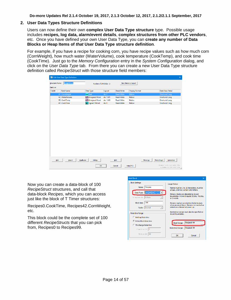
2. User Data Types Structure Definitions
Users can now define their own complex User Data Type structure type. Possible usage includes recipes, log data, alarm/event details, complex structures from other PLC vendors, etc. Once you have defined your own User Data Type, you can create any number of Data Blocks or Heap Items of that User Data Type structure definition.
For example, if you have a recipe for cooking corn, you have recipe values such as how much corn (CornWeight), how much water (WaterVolume), cook temperature (CookTemp), and cook time (CookTime). Just go to the Memory Configuration entry in the System Configuration dialog, and click on the User Data Type tab. From there you can create a new User Data Type structure definition called RecipeStruct with those structure field members:
Now you can create a data-block of 100 RecipeStruct structures, and call that data-block Recipes, which you can access just like the block of T Timer structures:
Recipes0.CookTime, Recipes42.CornWeight, etc.
This block could be the complete set of 100 different RecipeStructs that you can pick from, Recipes0 to Recipes99.

Do-more Updates Rel 2.1.4 October 19, 2017, 2.1.3 October 12, 2017, 2.1.2/2.1.1 September, 2017
Page 15 of 57
You can also create a new heap-item of a single RecipeStruct as the current recipe and call it CurrentRecipe.
Then you can move one of the RecipeStructs in the Recipes block to the CurrentRecipe heap-item using array indexing based on a user selection by setting V100 equal to a recipe index number from 0 to 99.
Then in your Ladder Logic, use CurrentRecipe.CookTime as the Preset to your TMR instruction.
Import/Export User Data Type Definitions Between Projects - Any User Data Type definition can easily be re-used in other Do-more projects by simply using the Import or Export buttons from the Memory Configuration’s User Data Types dialog. You can then easily share User Data Type data between Do-more PLCs via RX/WX Network Read/Write instructions, like updating recipes across multiple PLCs. Copy/Paste of Ladder Logic that reference elements of a User Data Type will also automagically paste the User Data Type definition and the corresponding data-block or heap-item to the destination project.

Do-more Updates Rel 2.1.4 October 19, 2017, 2.1.3 October 12, 2017, 2.1.2/2.1.1 September, 2017
Page 16 of 57
3. Load Project Image from SD Card in BRX PLC
If an SD Card contains a PLC image file with the name image.bin in the root folder, then when
the PLC is rebooted with the Mode Switch in the STOP position, the BRX PLC will load and save that project image as its new project.
This image file contains the 3 critical areas of your project: System Configuration, Program, and Documentation. It also can optionally contain the Image Register’s Retentive Memory values, User Password Configuration, and IP Network Configuration.
This is a great feature for OEMs that need to replicate a PLC’s contents over and over again, without the need for using Do more Designer. Just create an image on an SD Card, stick it in a new BRX PLC that is powered down, put the Mode switch to the STOP position, then TURN IT ON.
There are also some optional security features similar to what are in the DmLoader utility, like requiring a valid password to be defined in the PLC, or requiring a matching Product ID. If these optional security features are defined but fail, the PLC contents remain as-is and are NOT updated
with the contents of the image.bin file. The result of the restoration is logged to the PLC’s
System Log.
There are two ways to generate a BRX PLC image file:
from Designer via PLC->Create PLC Image File menu (see dialog box to the right)
using the new BACKUP – Create PLC Image File instruction
The BACKUP – Create PLC Image File instruction lets you create image files on-the fly at runtime. Great for automatically making PLC image backups on a weekly or monthly basis. This is a GREAT feature for places that need to make a backup of the PLC system including the Image Register’s Retentive Memory contents.
See Help topic DMD0425 – Backup and Restore Using Micro-SD Card for all of the details.

Do-more Updates Rel 2.1.4 October 19, 2017, 2.1.3 October 12, 2017, 2.1.2/2.1.1 September, 2017
Page 17 of 57
4. Instructions
To utilize any of the new PLC features, new instructions and instruction changes, the CPU firmware requires at least Do-more Technology Version 2.1 (see Help->Do-more Technology Versions when online). To upgrade your Do-more CPU firmware, select PLC->Update Firmware menu. The firmware files that shipped with this version support Do-more Technology Version 2.1: bxdm1x_2_1_0.os for BRX, h2dm1x_2_1_0.os for 205 Do-more CPUs, and t1hdm1x_2_1_0.os for the Terminator Do-more CPUs. Note that newer firmware files may already be available.
a. New Instructions
COPY – Copy Data lets you perform most of the data assignment operations in one compact instruction. It merges the functionality of MOVE, MOVER, and SETNUMR for numeric data; SET/RST, SETR/RSTR for bit data; copying entire structures and ranges of structures; and moving Strings of different maximum lengths between each other, for example moving SS0 to SL5. (5687)
BACKUP – Backup System lets you create an image of your PLC to a .bin file which can later be used to load that project into a BRX PLC without the use of Do-more Designer.
See the Load Project Image from SD Card in BRX PLC section above for more information.

Do-more Updates Rel 2.1.4 October 19, 2017, 2.1.3 October 12, 2017, 2.1.2/2.1.1 September, 2017
Page 18 of 57
DEBOUNCE – Reduce Discrete Input Chatter – software based "signal qualifier" on the powerflow input. The graph in the instruction editor below details its behavior.
FLASHER – Cycle Output ON/OFF lets you define the flashing cycle of a bit output. It even supports lopsided ON/OFF times, and variable time.
TIMEDOUT – Timed Output sets the Output for a predetermined amount of time based on the powerflow into the box. The Output can be ON longer if the "Maintain Output" option is checked and the input powerflow is ON when the Minimum On Time expired.

Do-more Updates Rel 2.1.4 October 19, 2017, 2.1.3 October 12, 2017, 2.1.2/2.1.1 September, 2017
Page 19 of 57
5. Project Notes Document
The new Project Notes document is a place where you can make general notes about your project. It is saved as part of your Do-more project on Disk and in the PLC, and can be printed out as part of your project’s hardcopy.
The editor/viewer is accessed within the Dashboard’s Documentation panel, or via the Tools->Edit Project Notes menu. It is a simple editor that contains simple text, but gives you a place to jot notes about work done, work needed to be done, design details, etc.
The document supports up to 60,000 characters (or 60 pages).
In the Download Project to PLC dialog, there is an option to prepend some text to the Project Notes document every time you download something to the PLC.
If anything is entered there, that entry is prepended to the top of the Project Notes document with the current date/time stamp and the current User Name that performed the download.
It is probably good practice to always enter something there, especially after commissioning your PLC. This way you can have a “paper trail” of any changes made to your PLC.
6. New System Words (DSTs)
DST51
DST389
DST390
DST391
DST392
$FatalTermCode
$ImageBackup
$ImageRestore
$ImagePassword1
$ImagePassword2
see Help Topic
DMD0208 System
Nickname Locations and
DMD0425 Backup and
Restore Using Micro-SD
Card for details

Do-more Updates Rel 2.1.4 October 19, 2017, 2.1.3 October 12, 2017, 2.1.2/2.1.1 September, 2017
Page 20 of 57
7. Enhancements
a. Timer structures – Added AB/Rockwell Timer bit fields, specifically .TT (Timer Timing), .DN (Done), .EN (Enabled). These bits behave just like the AB Timers do. The behavior of the existing Do-more Timer bits has not changed. Use whichever bits you like.
b. Common Timer Instruction Editor – provides details about the behavior of each different Timer instruction in the Do-more control engine. The editor comes up by default when you create any new Timer instruction (TMR, TMRA, ONDTMR, OFFDTMR, TMRDOWN, TMRADOWN, TMRAG) (5736).
As you cycle through the different Timer instruction radio buttons in the top/left, the Input Leg and Timing diagram descriptions change, providing details about that specific Timer instruction. This makes it easy to see the differences between the various Timer instructions, giving you the information you need to choose the best Timer for the task at hand.
Whenever you edit an existing Timer instruction, the instruction specific editor is used, not this Common Timer editor (you can change that behavior via the Ladder View Options dialog if you want it to always show up, or to never show up). You can also disable the launching of this new Common Timer editor by checking the Do not use this again checkbox at the top/right of the editor. If disabled, Designer will always bring up the default instruction specific editor, not this Common Timer editor, regardless of whether it’s a new or existing Timer instruction.
If you are familiar with AB’s Timer behaviors, there is also a checkbox at the top to diagram the new AB Timer Structure bit behaviors for each Timer instruction (see previous item for details).
c. General security enhancements (2.1.2).
d. Dashboard – When the Reload button is hit when Online to a PLC, the current I/O Configuration in Designer is compared with the actual I/O Configuration in the PLC at that time. If any differences are found, user is given an option to reload actual the I/O Configuration from the PLC into the Dashboard View.
e. Dashboard – Clicking on a CTRIO module in the Dashboard’s base display will now give you the option to open the Monitor CTRIO Module dialog when you are online with a PLC (5694).
f. Dashboard – A new item exists under the I/O panel: Local I/O Configuration Mode as being either Auto or Manual. Clicking on that item takes you to the I/O Configuration page in the System Configuration dialog to change the mode.

Do-more Updates Rel 2.1.4 October 19, 2017, 2.1.3 October 12, 2017, 2.1.2/2.1.1 September, 2017
Page 21 of 57
g. Launch Pad – The Projects list, Applications list, and Links list are simple lists with simple scrolling and sorting behavior. The Projects list has columns for the Project name and Last Modified date-time stamp. The Links list has columns for the Link Name and PLC Type:
h. Stage Jump Instructions - All of the instructions that support the Stage JMP operation now offer the option to automagically create THAT Stage bit’s SG instruction if the stage bit is new for the current code-block. If the option is enabled, there are 2 options on where to place the new SG instruction, either below the current rung OR at the end of the code-block. It is smart enough to know to NOT create the SG instruction if it already exists for that Stage Bit, so you can just keep it checked all the time if you like the feature (5690).
i. Options Dialog now prompts you if you did not check the Apply Options To: New Views checkbox (5853).
j. BRX High Speed Counter - added Retentive Accumulator option (non-retentive by default).

Do-more Updates Rel 2.1.4 October 19, 2017, 2.1.3 October 12, 2017, 2.1.2/2.1.1 September, 2017
Page 22 of 57
k. System Configuration – The Memory Configuration Entry in the dialog has been divided into 3 tabs: 1. Memory Blocks, 2. Heap Items, and 3. User Data Types:
l. MATH Editor now warns if the Expression is performing INTEGER arithmetic but the Result parameter is REAL (5860).
m. Instruction Editor - The validation mechanism now supports reporting Errors, Warnings, and Messages (3853):

Do-more Updates Rel 2.1.4 October 19, 2017, 2.1.3 October 12, 2017, 2.1.2/2.1.1 September, 2017
Page 23 of 57
n. Instruction Editor - Currently, whenever an instruction’s editor knows something is invalid, it shows a red bulb in the edit dialog box’s title bar. Next to the red bulb, it will remind you to Hit Enter for Error Details (see next item).
So whenever you see the red bulb, just hit Enter key for all of the details (5742).
o. Dashboard and System Configuration I/O Configuration - Modules in the base display have "Configure Module" added to their left-click popup tip if they are configurable.
p. Ladder View – Changed default ladder Background Selection color to match Windows 10 selection color. Previous default color was too dark and made element text difficult to read.
q. Ladder View – Adjusted Online Status Data Format Context Menu entries.
r. Ladder View – Added third Option for showing lengthy instruction details for most instructions (do not bother showing long AXCAM table, but show CALL subroutine parameters); this is the default, but the default for Print Ladder is to show All Details (5696).
s. Data View - Made grid lines more visible. You can turn grid lines OFF in Data View’s Options dialog. (5771).
t. Trend View – Save Log File’s Browse button’s Save-As dialog now defaults to the directory and the file name specified in the File Name field (5243).
u. Trend View – can add a range of Stage Bits (5647).
v. Dashboard and I/O System View – show when too many modules are installed (5851).
w. Video Library - Automatically refreshed when you launch the Browse Videos dialog.
x. Error, Warning, Message Report dialogs - now have a Copy to Clipboard button.
y. Instruction Toolbox - Has option to show Instruction Help in a tooltip as you hover over an instruction’s mnemonic in the Toolbox. To turn that option OFF, right click on the Toolbox and UNcheck the Show “Help” Tooltip menu option (5672).
z. FILELOG Instruction - automagically prefers nicknames over element names for the header line of the CSV file.
aa. AXPOSTRAP – Axis Move to Position Using Trapezoid – Instruction editor better clarifies the Multi-Move steps and behavior.
bb. AXCAM, AXGEAR, and AXFOLLOW Editors – Warn when the selected Master Register is an unconfigured High Speed Ctr/Tmr (5697).

Do-more Updates Rel 2.1.4 October 19, 2017, 2.1.3 October 12, 2017, 2.1.2/2.1.1 September, 2017
Page 24 of 57
cc. RX/WX – Network Read/Write – The Table Entry Editor dialog makes it clearer when entering the Remote Memory Block when it is a Built-In vs. a User data-block. It now uses radio buttons for Built-in vs. User, uses simple element entry when it is Built-In, and relabeled the Remote block type’s “ID” field to “Address” (5778).
dd. HWINFO – Get Hardware Information - Instruction editor’s I/O Master combo box is no longer sorted alphabetically, but in Master order: @LocalIOMaster, then @EthIOMaster, then … (5763).
ee. DirectLOGIC Migration Utility supports the DL-454 CPU.
ff. Import Project - Instruction parameter errors are reported with more detail.
gg. Project Information Dialog (File->Properties) – Has an Update Default Values button to save off the current Company, Department, and Programmer fields, which will be used as default values on any new projects.
hh. System Information Dialog (PLC->System Information) System Status tab shows the $FatalTermCode DST51 value for CPUs running Do-more Technology version 2.1 or later (see section 6. New System Words (DSTs) above) (5850).
ii. Program Check - Now utilizes a modal Operation Status Dialog in lieu of just a Wait Cursor because some projects can be quite complex. The Operation Status Dialog’s Percentage Complete feedback is much more helpful than just a spinning wait cursor.
jj. New Program Check rules:
W131 Instruction parameter is referencing a 16 bit unipolar WX/WY analog element without Unsigned cast ":U" (need to change WX42 to WX42:U) Whenever you configure an analog channel to be 16 bit unipolar, the cast is needed since unipolar 16 bit values have an unsigned range of 0 to 65535, but native WX/WY are signed range of -32768 to +32767. So a maxed-out WX42 signal WITHOUT the :U cast would evaluate to -1, but it should evaluate to 65535. WX42:U will evaluate properly to 65535. So the warning just tells you to replace your WX42 with WX42:U.
E094 High Speed I/O cannot be mapped to a different address On BRX PLC systems, the accelerated hardware I/O interface requires the I/O mapping remain as-is, starting at X0 and Y0 (5818).

Do-more Updates Rel 2.1.4 October 19, 2017, 2.1.3 October 12, 2017, 2.1.2/2.1.1 September, 2017
Page 25 of 57
8. Adjusted Anomalies
a. RX/WX Instruction’s Read From and Write To table entry editors’ Remote ID and Number of Element edit fields now correctly load the instruction’s values, instead of always loading the default values of 0 and 1.
b. CALL instruction being read from the PLC now correctly decodes setting range of bits to 1. Was incorrectly decoding a range of bits set to 1 as a range of bits being set to 0, not to 1 (5804).
c. Memory Editor’s and Memory Image Manager’s Import Memory function correctly handles importing long strings (5557).
d. The list of blocks in the "New Memory View" dialog is now sorted alphabetically (5756).
e. Dashboard’s serial port/serial POM tooltips and click behaviors properly adjust when any changes are made to their configuration.
f. Dashboard correctly showing manually mapped I/O points.
g. Dashboard’s Add a Module hotspot no longer overlaps the scrollbar (5721).
h. Dashboard better handles drawing and resizing.
i. Dashboard Base Display no longer tries to refresh itself while the System Configuration is being redefined, specifically during Read from PLC and Clear PLC operations.
j. Dashboard BRX SD Card hot spot always will launch the Browse PLC File System dialog regardless of whether any media exists or is mounted (5650).
k. Launch Pad’s Links list better handles unknown links.
l. Ladder View – Relational Contact instruction properly displays different sized left-side and right-side parameters/status.
m. Ladder View – Relational Contact has correct rung row height when using Symbolic Constant or Unassigned Nickname with Elements turned OFF but Nicknames turned ON (5872).
n. Ladder View – Box instructions properly calculates their widths in display mode and in status mode.
o. Ladder View – instruction editors with tables properly handle ordering of the Create Unassigned Nickname dialog and Error dialog (5873).
p. Ladder View – corrected MOVE instruction width calculation (5821)
q. Ladder View – optimized Relational Contact column’s screen real estate (5685).
r. Ladder View – instruction editor widths corrected when zoom level was less than 100%.
s. Ladder View – properly filling out INTCONFIG – Configure Interrupt instruction’s Match Register Fire ISR When combo box.
t. Ladder View – NETTIME – SNTP Client editor for a new NETTIME instruction no longer tries to determine the current DNS IP address resolution for ntp2.hosteng.com. This was causing LONG delays if your PC was not connected to the Internet. Recommend using DNSLOOKUP’s Variable IP Address and the DNSLOOKUP – Name to IP Address instruction, and resolving your SNTP server IP Address at runtime (5504).
u. PACKETOUT – Output Data to Packet Device instruction editor supports broadcast address in the Fixed Address field (5549).
v. Trend View properly handles ranges of casted elements (5647).
w. Import Trend Archive utilizing Operation Status Dialog to keep the user interface responsive (5431).

Do-more Updates Rel 2.1.4 October 19, 2017, 2.1.3 October 12, 2017, 2.1.2/2.1.1 September, 2017
Page 26 of 57
x. When multiple PID Views are opened, closing one PID View no longer stops the communication for the remaining PID Views. Opening a non-maximized PID View properly shows the Form section of the PID View. Opening a project file/workspace that had been closed with multiple PID Views opened, now correctly re-opens all of those PID Views (5371, 5375).
y. Data View – When you Monitor Data to a Data View, the new Data View now automatically turns Status ON.
z. I/O System View no longer causing menus to collapse (5737).
aa. Changed velocity range minimum value from 0 to 10 in AXCONFIG (Min & Max velocity) AXJOG (Target Velocity) AXSETPROP (Min & Max velocity) AXPOSSCRV (Max velocity) AXPOSTRAP (Max velocity) (5714).
bb. Added a warning to AXPOSTRAP when Multi-move is picked but the Position Value is a constant (should be a variable when using Multi-move) (5809).
cc. Corrected LERP instruction’s display when in “short summary” mode.
dd. STREAMOUT instruction editor now correctly reports valid state related to the Flush INPUT device first checkbox.
ee. RX/WX Network Read/Write instruction editor’s Remote Password no longer reports certain error conditions as being “valid”.
ff. Adjusted the set of instructions which are allowed in a SUBROUTINE (5730).
gg. Creating Interrupt Service Routine (ISR) works correctly for all BRX MPU projects (5687).
hh. Adjusted/Corrected Trend Instruction (5695, 5537):
AXCAM, AXFOLLOW, AXGEAR missing Master Velocity
AXGEAR missing Slave Position
FREQTMR, FREQCNT show rate and the accumulator in 2 separate panes
DTCMP shows the comparison bits in 1 pane, and the individual Date/Time fields in individual separate panes
File instructions (FILE****) show File System and/or File Handle details
String instructions (STR****) no longer show useless flag constants
CALL shows input/output parameters
ii. Can now delete a module in an Ethernet I/O base (5718).
jj. System Structures are updated where needed.
kk. Right clicking in the "empty" area of the MDI tab bar no longer brings up an empty context menu (5595).
ll. When resizing the Folder Settings dialog, the new Video Folder controls resize/move correctly (5681).
mm. Better maintaining Parent/Child window relationship with Dashboard and System Configuration dialog boxes.
nn. Import/Export Project supports all of the various BRX MPU models (5616).
oo. Reduced communication errors during Clear PLC operation, which writes to Flash ROM.
pp. Added Validation to System Configuration.
qq. Differences between PLC and Disk Ethernet Remote I/O configurations correctly identified.
rr. Program Check rule for detecting Unassigned Nicknames at download time now detects them within “complex” instructions like MATH (5715).
ss. Communication Server better handles <NAK> responses from PLC.

Do-more Updates Rel 2.1.4 October 19, 2017, 2.1.3 October 12, 2017, 2.1.2/2.1.1 September, 2017
Page 27 of 57
tt. Communication Server does not include Modem devices by default. Change the INI File setting [devasync.dll] ModemEnable=1 to bring it back.
uu. System Information/System Log dialog properly handles invalid log entries.
vv. Print Script parser correctly reports string literals that exceed the maximum length, and reports scripts that are too long. This was happening in the new FILELOG instruction if you entered too many entries.
ww. Better handling of large Trend Archive files (5431).
xx. Browse Videos dialog remembers the column settings from one session to the next.
yy. Cross Reference handles casts with array references. e.g. D[V0]:B3.
zz. Create Nickname dialog handles structure fields with nicknames at the structure level (5827).
aaa. Create Nickname dialog handles a constant parameter (5525).
bbb. Documentation Editor’s Add Record handles Increment Nickname After Add when the Nickname exceeds the maximum length (5830; thanks to MW@WSS).
ccc. Documentation Editor’s Add Record auto-increment feature handles casts (5702)
ddd. Documentation Editor more stable (5279).
eee. Migrate DirectSOFT Project no longer fails when the DirectLOGIC project contains an ECEMAIL instruction with an empty To: field, which is common when a long To: list is configured in the ECOM100 module itself (5828 – thanks to JS in Ohio).
fff. Migrate DirectSOFT Project calculates DirectLOGIC’s ONDTMR and OFFDTMR Preset as hundredths of a second (5251; thanks to SL@MWP).
ggg. Resolve Online/Offline Differences dialog’s description of Documentation content now lists Project Notes and Ignored Program Check Rules. These were always part of the Documentation, they just weren’t mentioned here.
hhh. View Manual and View Specs context menu items for GSE Drive modules in I/O Configuration dialog and I/O System View are working correctly (5322).
iii. Manually changing GSE Drive type works correctly.
jjj. Updated various Message Boxes that accessing the firmware download dialog can be done using the PLC->Update Firmware menu.
kkk. Parent/Child Window ordering adjusted (5784, 5797).
lll. Provide more information when a desired PLC operation fails due to the current User’s Security Privileges being insufficient, for example "Cannot write data to PLC! Current user doesn't have Write Data (WD) security privilege" (4134).
mmm. Export Element Documentation in the new C-more format WITH Struct Fields properly exports when you have checked Also export USED elements which do not have a nickname option (5793).
nnn. Corrected the lookup of an instruction’s absolute address (5473).
ooo. Corrected ordering of the Element Picker dialog and the Create Data Block dialog (5879).
ppp. Dynamic system and User Data Type schema size changes propagated to corresponding heap-items and memory data blocks (2.1.4) (5914).
qqq. Corrected Program Check rule for Do-more Technology Version 2.1 validation of BRX Analog Module support (2.1.3).
rrr. Ladder View – added status to Called Counter parameter in CALL instruction (2.1.2).

Do-more Updates Rel 2.1.4 October 19, 2017, 2.1.3 October 12, 2017, 2.1.2/2.1.1 September, 2017
Page 28 of 57
sss. Added pop-up Help content for new 2.1 instructions (2.1.2).
ttt. Download Project dialog’s Prepend Project Notes field word-wraps (5877) (2.1.2).
uuu. FILELOG correctly performs Replace operation (5878) (2.1.2).
vvv. Reworded Output Window Warning message when Designer’s Memory Configuration is incompatible with the PLC’s; it now tells you what to do to resolve this, specifically either Write Designer’s project to PLC or Read the PLC’s project into Designer, but also offer to open up Program Compare to help resolve differences just by double-clicking on the Warning in the Output Window.

Do-more Updates Rel 2.0, February, 2017
Page 29 of 57
The significant new feature in Do-more 2.0 is the
introduction of the new BRX line of Micro PLCs.
However, there are many cool features in 2.0
that enhance the entire product line. The first
part of this document will highlight the new BRX
platform and features; the last part of this
document will highlight the common features
across all Do-more platforms (205, Terminator,
Simulator, and BRX).
Before diving into the new BRX line of PLCs, there are some key user interface enhancements which will help you with your work flow.
Dashboard View
The new Dashboard view is a one-stop-shop for getting status of your PLC, configuring the “screw-head” centric pieces of your project along with configuring many other areas, and as a general software navigation tool. All the existing Menus, Toolbars, and Hot Keys are also still around and still work, so continue to use those if you like (however, even some “experts” have admitted to liking this new user interface!) It’s even more powerful if you have multi-monitors or a wide monitor and “tear it off” and
access it outside the Designer window frame (see Float/Dock button on view’s left-toolbar).
Float your mouse cursor over the picture of your PLC model and suddenly all the hot-spots are
highlighted. Float over a hot spot to get general information about that specific area of the hardware.
Right click on a hot spot to get a context specific menu. Left click on a hot spot and get a Pop-up Tip
that will contain information and hot links to other areas of Designer related to that hot spot.
Each of the Panels that surround your PLC graphic relates to a specific area of your current project
(Program, Documentation, Communications, I/O, CPU, Memory, Devices). Within each panel are

Do-more Updates Rel 2.0, February, 2017
Page 30 of 57
project status information items, most of which are also hot links. Again, float your cursor over each
one to get more detailed status information about that item. Click on the hot linked items and it will
either show a Pop-Up Tip with more navigation options, or will take you directly to the
configuration/status dialog related to that item.
Built-in Video Training has been integrated into Do-more Designer, whether it’s learning how to
configure an analog module, or learning the basics of Designer 2.0, video help is just 1 or 2 mouse
clicks away.
New Start Page Videos
The Start Page has been changed to provide hot link buttons to play 5 new videos that will help you get up and running with Designer 2.0.
1. Welcome to Designer 2.0 2. How to Create a Simple Program 3. Troubleshooting Tips 4. Do-more PLC Architecture 5. Helpful Hints
The 6th button lets you navigate, play and optionally download any/all the hundreds of short videos (details below).
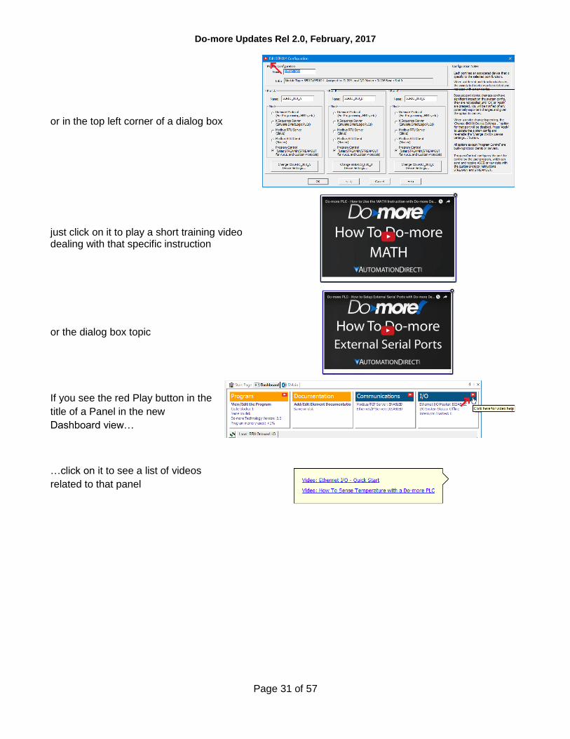
If you ever see the red Play button in the top toolbar of an instruction editor
Do-more Updates Rel 2.0, February, 2017
Page 31 of 57
or in the top left corner of a dialog box
just click on it to play a short training video dealing with that specific instruction
or the dialog box topic
If you see the red Play button in the
title of a Panel in the new
Dashboard view…
…click on it to see a list of videos
related to that panel

Do-more Updates Rel 2.0, February, 2017
Page 32 of 57
New BRX Micro line of PLCs
General BRX Micro PLC Features
All of the various BRX Micro PLC Units (MPUs) are stackable, with built-in Power Supply/CPU,
varying in size from no onboard I/O, up thru 36 points of onboard I/O. Most MPUs support up to 8
stackable modules, able to handle over 160 I/O locally (Ethernet units can support thousands of
I/O via Ethernet I/O). Many MPUs have at least two analog I/O channels onboard.
The mix of Power-Supply/Input Types/Output Types/Ethernet in the BRX line result in 38 different MPU
models (sub-types). The new File->New->Offline Project dialog highlights the key differences between
MPU sub-types, helping to make the selection easier. After selecting the BRX Hardware Class, then
Ethernet vs. non-Ethernet Type, you get a list of all the possible MPU sub-types, with key specification
features listed below a picture of the selected sub-type MPU model:
Do-more Updates Rel 2.0, February, 2017
Page 33 of 57
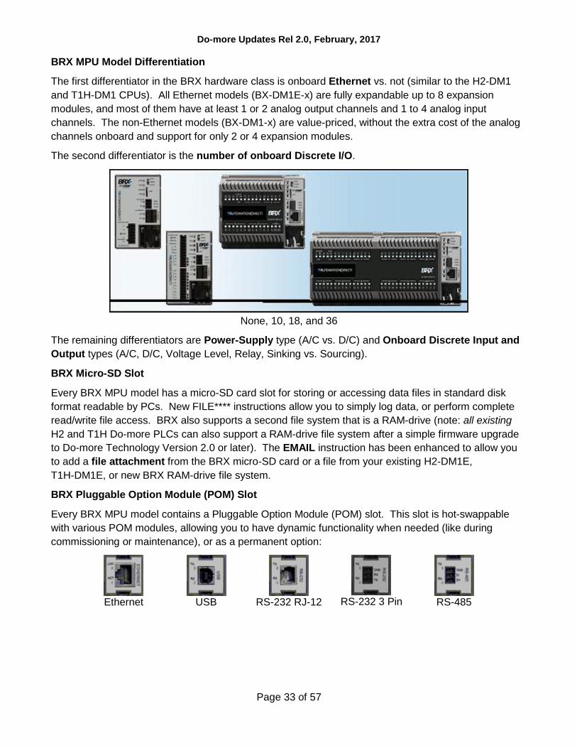
BRX MPU Model Differentiation
The first differentiator in the BRX hardware class is onboard Ethernet vs. not (similar to the H2-DM1
and T1H-DM1 CPUs). All Ethernet models (BX-DM1E-x) are fully expandable up to 8 expansion
modules, and most of them have at least 1 or 2 analog output channels and 1 to 4 analog input
channels. The non-Ethernet models (BX-DM1-x) are value-priced, without the extra cost of the analog
channels onboard and support for only 2 or 4 expansion modules.
The second differentiator is the number of onboard Discrete I/O.
None, 10, 18, and 36
The remaining differentiators are Power-Supply type (A/C vs. D/C) and Onboard Discrete Input and
Output types (A/C, D/C, Voltage Level, Relay, Sinking vs. Sourcing).
BRX Micro-SD Slot
Every BRX MPU model has a micro-SD card slot for storing or accessing data files in standard disk
format readable by PCs. New FILE**** instructions allow you to simply log data, or perform complete
read/write file access. BRX also supports a second file system that is a RAM-drive (note: all existing
H2 and T1H Do-more PLCs can also support a RAM-drive file system after a simple firmware upgrade
to Do-more Technology Version 2.0 or later). The EMAIL instruction has been enhanced to allow you
to add a file attachment from the BRX micro-SD card or a file from your existing H2-DM1E,
T1H-DM1E, or new BRX RAM-drive file system.
BRX Pluggable Option Module (POM) Slot
Every BRX MPU model contains a Pluggable Option Module (POM) slot. This slot is hot-swappable
with various POM modules, allowing you to have dynamic functionality when needed (like during
commissioning or maintenance), or as a permanent option:
Ethernet
USB
RS-232 RJ-12
RS-232 3 Pin
RS-485

Do-more Updates Rel 2.0, February, 2017
Page 34 of 57
BRX Expansion Modules
Initially, the BRX line of PLCs supports 27 different I/O modules (more modules planned):
10 different Discrete Input modules
12 different Discrete Output modules
5 different Discrete Input/Output Combination modules
Coming soon:
8 different Analog Input modules
4 different Analog Output modules
Other expansion modules are in-work and are planned to be released soon.
BRX Onboard High Speed I/O
Most of the BRX models support some combination of High Speed Inputs and/or High Speed Outputs
onboard (no extra cost). Both Input and Output frequencies support up to 250K Hz.
Specific Onboard High Speed Input features include
High Speed Counting (Up, Down, Quad, Bi-directional, Up-Down)
High Speed Timing (Single Edge, Dual Edge)
Interrupts (Discrete Input Event of Rising/Falling/Either with optional Hi/Lo Level “permissives”
of any/all other onboard inputs)
Specific Onboard High Speed Output features include
Axis Motion (Step/Direction, Clock-wise/Counter-clock-wise, Quadrature emulation) using
various AX* instructions (AXJOG, AXHOME, AXPOSTRAP, AXPOSSCRV, AXVEL, AXGEAR,
AXFOLLOW, AXCAM, et.al.); up to 4 Axis (1 virtual Axis, up to 3 tied to actual outputs)
Pulse Width Modulation configured via the PWM structure members .Period and .DutyCycle
Table Driven Output using TDO* instructions (Programmable Limit Switch; Preset Table script
of various Set, Reset, Toggle, Pulse On, Pulse Off after micro-second duration)
BRX Onboard Analog Configuration
The BRX MPU units that come with onboard Analog Inputs and Analog Outputs let you fully and
independently configure each analog channel’s electrical characteristics, so there is no need to
qualify these when purchasing, or buy multiple module types for different signal types!
current vs. voltage
unipolar vs. bipolar
voltage range
resolution (14, 15, 16 bits)
optionally scale WX analog input to new RX (Real Analog Input) data-block
or from new RY (Real Analog Output) data-block to WY analog output,
with or without clamping
Do-more Updates Rel 2.0, February, 2017
Page 35 of 57
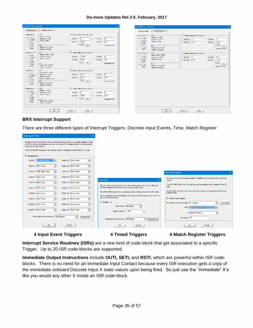
BRX Interrupt Support
There are three different types of Interrupt Triggers: Discrete Input Events, Time, Match Register:
4 Input Event Triggers 4 Timed Triggers 4 Match Register Triggers
Interrupt Service Routines (ISRs) are a new kind of code-block that get associated to a specific
Trigger. Up to 20 ISR code-blocks are supported.
Immediate Output Instructions include OUTI, SETI, and RSTI, which are powerful within ISR code-
blocks. There is no need for an Immediate Input Contact because every ISR execution gets a copy of
the immediate onboard Discrete Input X state values upon being fired. So just use the “immediate” X’s
like you would any other X inside an ISR code-block.

Do-more Updates Rel 2.0, February, 2017
Page 36 of 57
INTCONFIG – Configure Interrupt Instruction
The configuration of any Interrupt Trigger can be changed dynamically at runtime using the INTCONFIG - Configure Interrupt instruction, including remapping the associated ISR code-block. The INTCONFIG instruction can be used within an ISR code-block for some pretty powerful program control. For example:
Dynamically control a high resolution discrete output using calculated timing values to reconfigure the Timed Event Trigger within the current ISR.
Follow-up a Discrete Input Event with a calculated Timed Event Trigger within the Input Event ISR.
Tweak the Match Register condition to the “next” Match Register condition within the ISR.
Any combination of Trigger settings and/or ISR code-block binding
Other Interrupt instructions include INTSUSPEND – Suspend Interrupts, INTRESUME –
Resume Interrupts, and INTDECONFIG – Deconfigure Interrupt Trigger Resource.
High Speed I/O
CTRIO functionality for BRX platform has been replaced with the following onboard resources that
come with nearly every BRX MPU model:
Counter/Timer Functions
Axis/Pulse Outputs
Pulse Width Modulation
Table Driven Output
New Motion Control: Axis
Every BRX MPU model supports up to 3 Axis Pulse Output resources (a fourth Axis is permanently
“Virtual”, meaning it cannot be tied to any physical pulse outputs, but can still be used to generate
logical pulse counts using any of the AXIS* instructions, just like the other “hard-wired” axis).

Do-more Updates Rel 2.0, February, 2017
Page 37 of 57
Each Axis can be configure as:
Virtual (does not drive any physical I/O)
Pulse Output Step and Direction
Pulse Output Clockwise/Counter Clockwise Selection
Pulse Output Quadrature (emulates a 4x quadrature sequence)
Except for Virtual, the other modes physically bind to two different onboard Discrete Y outputs.
At runtime, the detailed configuration of an AXIS must be configured using the AXCONFIG – Configure Axis instruction.
AXJOG – Axis Jog Mode
It is a 3-input leg instruction to perform a simple “jog”. The input legs are
1. Enable/Reset 2. Forward 3. Reverse

Do-more Updates Rel 2.0, February, 2017
Page 38 of 57
AXHOME – Axis Perform Home Search
AXPOSTRAP – Axis Move to Position
Using Trapezoid
AXPOSSCRV – Axis Move to Position
Using S-Curve

Do-more Updates Rel 2.0, February, 2017
Page 39 of 57
AXVEL – Axis Set Velocity Mode
AXGEAR – Axis Electronic Gearing
AXFOLLOW – Axis Position Following
with Offset

Do-more Updates Rel 2.0, February, 2017
Page 40 of 57
AXCAM – Axis Electronic Camming
The AXCAM instruction also has an
online tool for easily editing/graphing
PLC Memory based Curve Fitting Points.
Access it via the PLC->Axis Cam Table
menu.
AXSETPROP – Set Axis Properties
AXRSTFAULT – Reset Axis Limit Fault

Do-more Updates Rel 2.0, February, 2017
Page 41 of 57
Pulse Width Modulation
Each BRX MPU supports up to 3 onboard Hardware Accelerated High Speed Output PWMs to precise microsecond or millisecond resolution. Once the PWM Output is configured, use the PWM’s heap item’s structure fields to control the PWM from your logic:
.Enable
.PeriodScale (bit 0: microsecond, 1: millisecond)
.Period (time value 0 to 65535)
.DutyCycle (real percentage 0.0 to 100.0)

Do-more Updates Rel 2.0, February, 2017
Page 42 of 57
Table Driven Output (TDO)
BRX supports up to 4 onboard Hardware Accelerated Table Driven High Speed Outputs in response to high speed Counters, Timers, and Pulse Outputs.
Use the TDOPRESET – Load Preset Table for Table Driven Output or the TDOPLS – Load
Programmable Limit Switch Table for Table Driven Output instructions to drive the high speed discrete
outputs.
TDOPRESET – Table Driven Output Preset Table
The TDOPRESET instruction also has an
online tool for easily editing PLC Memory
based TDO Preset Table. Access it via
PLC->TDO Preset Table menu.

Do-more Updates Rel 2.0, February, 2017
Page 43 of 57
TDOPLS – Load Programmable Limit Switch Table for Table Driven Output
The TDOPLS instruction also has an
online tool for easily editing and graphing
PLC Memory based TDO PLS Table.
Access it via PLC->TDO PLS Table
menu.
TDODECFG – Deconfigure Table Driven
Output
Configurable Discrete Input Filters
The onboard Discrete Inputs response
times are configurable on every BRX
MPU. Many of the MPU models’ Discrete
Inputs support very high frequency at the
hardware level (up to 250K Hz). These
response times can be configured through
the System Configuration’s Setup
Discrete Input Response Times dialog.
You can enter the filter in any of 3
different scales:
Frequency
Time in nanoseconds
Raw Clocks

Do-more Updates Rel 2.0, February, 2017
Page 44 of 57
New Features in Designer 2.0 for All PLC Lines, including Do-more Technology Version 2.0
The new Select Project dialog is the Launch Pad on steroids. It lists all your recent projects sorted by the Last Opened date by default, so your most recent projects are near the top.
You can sort by any of the columns, not just Last Opened:
Project name
Folder
Last Opened date/time stamp
Link name
Link Information
Link Description
PLC type
You can also create a New Offline Project, a New Online Project, or Browse to open up an unlisted
project file.
The dialog box is resizeable, so if you have the screen real estate, feel free to enlarge the dialog and
widen those columns. It remembers its location and sizes so that once you set it up, it will remember
from launch to launch. It automatically shows up at start-up, but you can disable that functionality by
UNchecking the checkbox in the lower left corner.
RAM Drive File System (DmT 2.0)
Do-more Technology Version 2.0 added a RAM Drive File System, so existing H2-DM1x, T1H-DM1x
CPUs can support the new FILE* instructions with a simple firmware upgrade (BRX supports it out of
the shoot; includes FILELOG, FILEOPEN, FILEREAD, FILEWRITE, FILECLOSE, FILEDEL,
FILECOPY, FILENEWFLDR, FILEQUERY, FILESYSCMD, FILESEEK, FILETRUNC).

Do-more Updates Rel 2.0, February, 2017
Page 45 of 57
The most useful FILE instruction is the new FILELOG – Log to File instruction. It makes data logging very simple, but very configurable.
The most common requirement is that you need a specific set of data points to be logged at a specific interval (once a day, once an hour, once a minute, etc.). Each FILELOG instruction lets you specify the desired interval and set of data points.
You can mangle the name of the .csv file starting with a “Base” .csv (Comma Separated Variable text file) name, appending the Date/Time stamp to the nearest hour, day, month, or year (e.g. “MyFILELOG” to the nearest day: MyFILELOG_y2016m12d07.csv). This is optional.
After uploading the file using the Browse PLC File System dialog to your PC, the resulting file contains a header line showing the PLC variable names, but always starts with the current Date/Time stamp. Then it will have all the log entries for each day/hour/minute/whatever. The example to the right may look like:
"TimeStamp(sec,local)","V100","V101","R100","CT0.Acc"
2016/12/7 18:09:00,42,256,3.14,199
2016/12/7 18:10:00,43,301,3.14,211
2016/12/7 18:11:00,57,301,2.82,0
The .CSV text file can be easily opened by Excel or Notepad or imported by most database programs.
You can also just log data on an event, not a periodic time interval. Just change the Input Leg setting
to Edge Triggered from Power Flow. Also, the Base .csv File Name can be a generating STRING
element (e.g. SS42) in case you want to come up with your own naming convention. Just use
STRPRINT to write to SS42.
Finally, if you want to attach these .CSV log files to an EMAIL, the Generate File Name checkbox will
come in handy to plug the Attachment file name in the EMAIL instruction (e.g. SS5 for the Generate
File Name parameter would contain MyFILELOG_y2016m12d07.csv from the first example above,
then use SS5 in your EMAIL instruction’s “Attach File Name” parameter.
If you want to do your own FILE I/O calls, the breadth and depth is typical. Note that not every file
system command is supported – this is a PLC not a PC, and some of those commands could take a
LONG time, like removing a folder. Hence, Remove Folder is not supported by Do-more. But if it’s

Do-more Updates Rel 2.0, February, 2017
Page 46 of 57
removable media, you can remove it from your PLC and put it on a PC and still do everything you want
to do from your PC (remove folders, format the media, run diagnostics, etc.).
FILEOPEN – Open File
FILEREAD – Read from File
FILEWRITE – Write to File
FILECLOSE – Close File
Do-more Updates Rel 2.0, February, 2017
Page 47 of 57
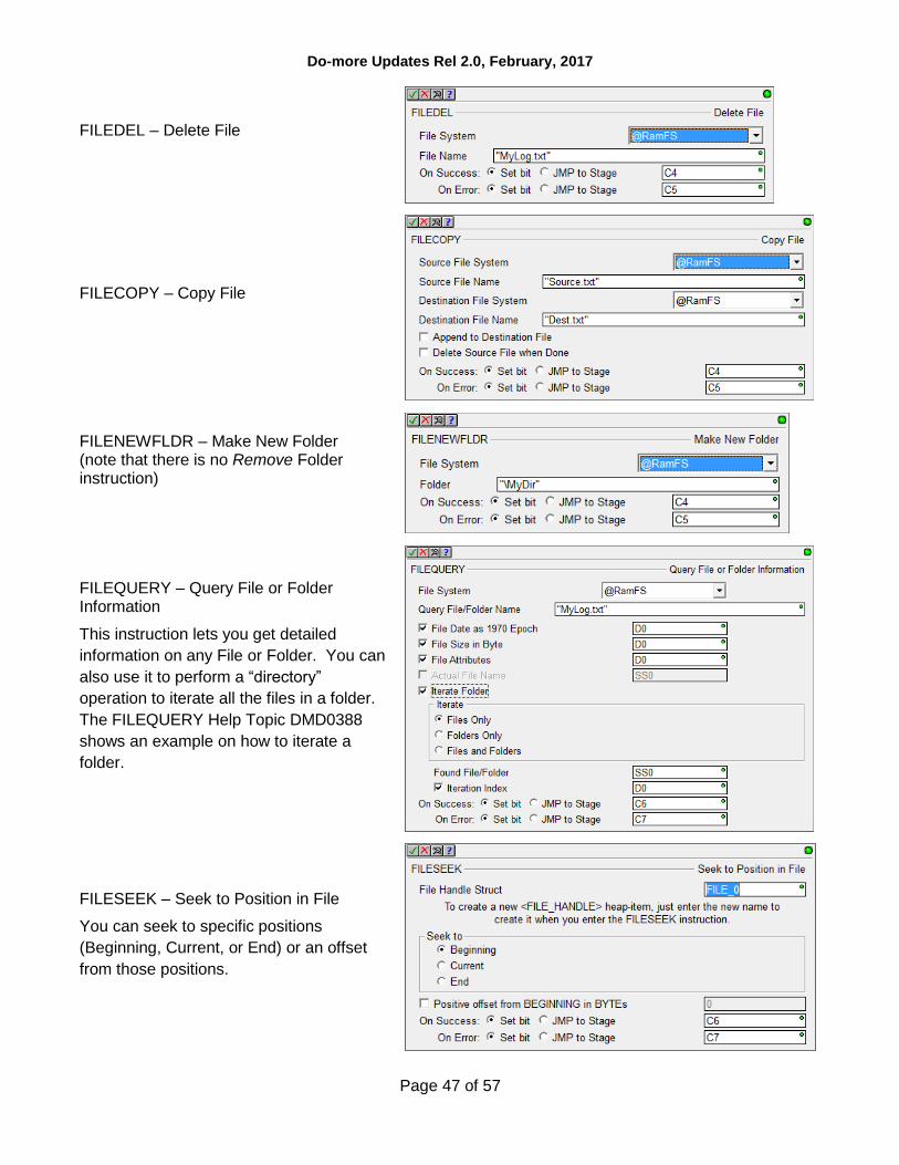
FILEDEL – Delete File
FILECOPY – Copy File
FILENEWFLDR – Make New Folder (note that there is no Remove Folder instruction)
FILEQUERY – Query File or Folder Information
This instruction lets you get detailed
information on any File or Folder. You can
also use it to perform a “directory”
operation to iterate all the files in a folder.
The FILEQUERY Help Topic DMD0388
shows an example on how to iterate a
folder.
FILESEEK – Seek to Position in File
You can seek to specific positions
(Beginning, Current, or End) or an offset
from those positions.

Do-more Updates Rel 2.0, February, 2017
Page 48 of 57
FILETRUNC – Truncate File
FILESYSCMD – Perform File System Command
Format (RAM Drive Only)
Dismount
Mount
It is very useful to programmatically Dismount the SD Card before an operator tries to remove the
media. The PLC’s MEM LED will be RED when it is fully dismounted and safe to remove the media.
Browse PLC File Systems Dialog (DmT 2.0)
This dialog lets you explore the SD Card and RAM Drive file systems in your Do-more PLC. You can copy files between your PC and PLC in both directions.
(see PLC->Browse PLC File Systems)
Do-more Updates Rel 2.0, February, 2017
Page 49 of 57
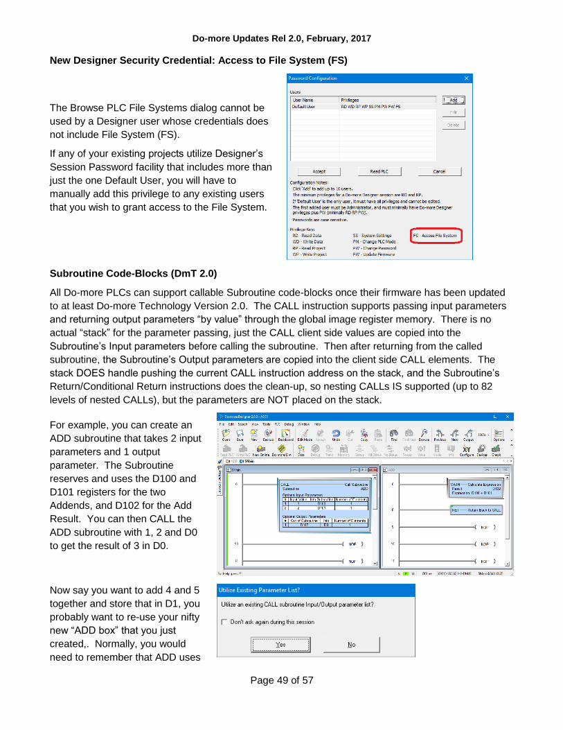
New Designer Security Credential: Access to File System (FS)
The Browse PLC File Systems dialog cannot be
used by a Designer user whose credentials does
not include File System (FS).
If any of your existing projects utilize Designer’s
Session Password facility that includes more than
just the one Default User, you will have to
manually add this privilege to any existing users
that you wish to grant access to the File System.
Subroutine Code-Blocks (DmT 2.0)
All Do-more PLCs can support callable Subroutine code-blocks once their firmware has been updated
to at least Do-more Technology Version 2.0. The CALL instruction supports passing input parameters
and returning output parameters “by value” through the global image register memory. There is no
actual “stack” for the parameter passing, just the CALL client side values are copied into the
Subroutine’s Input parameters before calling the subroutine. Then after returning from the called
subroutine, the Subroutine’s Output parameters are copied into the client side CALL elements. The
stack DOES handle pushing the current CALL instruction address on the stack, and the Subroutine’s
Return/Conditional Return instructions does the clean-up, so nesting CALLs IS supported (up to 82
levels of nested CALLs), but the parameters are NOT placed on the stack.
For example, you can create an
ADD subroutine that takes 2 input
parameters and 1 output
parameter. The Subroutine
reserves and uses the D100 and
D101 registers for the two
Addends, and D102 for the Add
Result. You can then CALL the
ADD subroutine with 1, 2 and D0
to get the result of 3 in D0.
Now say you want to add 4 and 5
together and store that in D1, you
probably want to re-use your nifty
new “ADD box” that you just
created,. Normally, you would
need to remember that ADD uses

Do-more Updates Rel 2.0, February, 2017
Page 50 of 57
D100 and D101 for the two input
parameters, and D102 for the one
output parameter.
So after you pick a new CALL
instruction, Designer knows that
Subroutines are meant to be re-
used, so it asks you if you want to
re-use an existing CALL signature
for the Subroutine-side parameters
for this new CALL box, and let you
fill out the CALL-side parameters:
After hitting OK, you are given a
more-than-half-filled-out CALL
instruction.
The Subroutine name, the
Subroutine’s side Input and Output
parameters are all filled out.
All that’s left to do is fill out the
three “red dot” empty parameters
that are the “caller side”
parameters (in this case, they will
be 4, 5, and D1)

Do-more Updates Rel 2.0, February, 2017
Page 51 of 57
It’s also good design to assign
Nicknames to the global
Subroutine input/output
parameters, then your CALL
instruction signature and
Subroutine logic looks even better
(e.g. ADD_Addend1,
ADD_Addend2, ADD_Result for
D100, D101, and D102,
respectively):
Enhanced New Offline Project Dialog
There is now a third selection level, PLC Sub-Type, which became necessary when the BRX was added due to the model/feature breadth of that new line. By adding PLC Sub-Type, this also allows for 205 Base Type selection, including an option of “unspecified”.
The dialog also reports on general features of the specific sub-type selected, highlighting key features in green (like built-in Ethernet, or onboard analog I/O or …; see other example in the BRX section above).

Do-more Updates Rel 2.0, February, 2017
Page 52 of 57
New Instructions and Instruction Enhancements
With the addition of a RAM Drive File System to all existing Do-more PLCs with just a simple firmware upgrade, the existing EMAIL instruction was enhanced to add some optional parameters for sending attachments.
A new STRPRINT/EMAIL Print Script command was created called TimeStamp() that optionally takes two parameters.
Resolution: min or sec (default) or tenths or hundredths or thousandths.
Clock-Time-Type: local (default) or utc
The format of the date portion is always YYYY/MM/DD. The format of the time portion is 24-hour, down to the specified resolution. So the default is local time to seconds resolution, for example:
2016/12/31 23:59:59
If you need more detailed formatting capabilities, use the existing FmtDate() and FmtTime() script
commands.
There is another STRPRINT/EMAIL Print Script command called Fill() that repeats the same character
multiple times. It takes 2 parameters:
Fill-character/byte as hexadecimal constant 0x00..0xFF
Fill-length (integer element or constant)
So, Fill(0x20, 80) would generate 80 spaces (0x20 is the ASCII hexadecimal constant for a
space).
ENDC – Conditional End of Code-Block
ENDC can be utilized in any PROGRAM, TASK or ISR code-block type. Although END coils are not
required by Do-more PLCs, the Conditional End within an Interrupt Service Routine is commonly
needed to help keep the ISR running as fast as possible.
Also, it is sometimes helpful to use END/ENDC for debug purposes to block out code execution in a
PROGRAM or a TASK. The ENDC box lets you do perform the End conditionally based on the input
contact power flow state of the rung.
Note that ENDC is different than the EXIT instruction in that ENDC can only end the current logic scan
of that code-block, it does NOT end the execution of that code-block for subsequent scans, like EXIT
does.

Do-more Updates Rel 2.0, February, 2017
Page 53 of 57
Instruction Toolbox
You can now hide any set of instruction
classifications that you don’t ever use, freeing
up more screen space in the Toolbox for the
instructions that you do use.
Just right click on the Instruction Toolbox and
select Hide/Show Classifications, then UNcheck
the classes you don’t ever use in the Show
Classifications dialog box.
Moved CTRIO set of instructions to its own Instruction Class.
Added a higher level Download Firmware dialog accessed via the PLC menu, PLC toolbar, and
Dashboard view. You can still download firmware from the System Information dialog.
New System Words (DSTs)
DST50
DST53
DST54
DST55
DST56
DST57
$InstalledPOM
$PLCSubType
$POMIpSetupSrc
$POMIpAddress
$POMIpNetmask
$POMIpGateway
see Help Topic DMD0208
System Nickname Locations
for details
Ladder View – added Ctrl+/ (control-slash) hot key to toggle documentation on/off quickly. Great
when online and needing more logic status real estate, Ctrl+/ turns off documentation temporarily to
give you more contacts/coils/boxes on your screen. Hit Ctrl+/ to bring it back to “normal”, Ctrl+/ to turn
it back off. Very handy when you just need to temporarily turn off documentation in your Ladder View.

Do-more Updates Rel 2.0, February, 2017
Page 54 of 57
Browse Videos Dialog
The new Browse Videos dialog box lets you navigate all the videos, and it supports keyword filtering
and title text search to watch any/all videos (see Help->Browse Videos).
Video Download Utility
The new Video Download utility can be especially helpful for installations where Internet access is
erratic or does not exist. By downloading relevant videos to your hard drive ahead of time, you can still
play these videos regardless of your Internet connection at those critical moments! (see
Help->Download Videos).
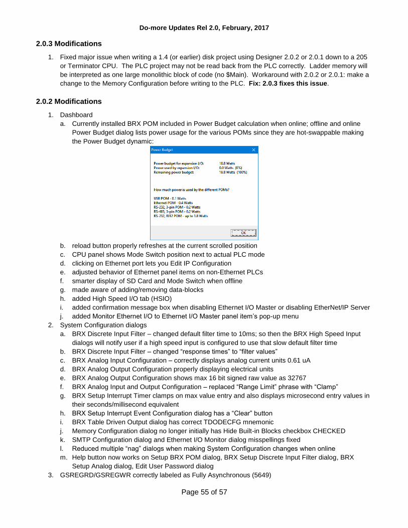
Do-more Updates Rel 2.0, February, 2017
Page 55 of 57
2.0.3 Modifications
1. Fixed major issue when writing a 1.4 (or earlier) disk project using Designer 2.0.2 or 2.0.1 down to a 205
or Terminator CPU. The PLC project may not be read back from the PLC correctly. Ladder memory will
be interpreted as one large monolithic block of code (no $Main). Workaround with 2.0.2 or 2.0.1: make a
change to the Memory Configuration before writing to the PLC. Fix: 2.0.3 fixes this issue.
2.0.2 Modifications
1. Dashboard
a. Currently installed BRX POM included in Power Budget calculation when online; offline and online
Power Budget dialog lists power usage for the various POMs since they are hot-swappable making
the Power Budget dynamic:
b. reload button properly refreshes at the current scrolled position
c. CPU panel shows Mode Switch position next to actual PLC mode
d. clicking on Ethernet port lets you Edit IP Configuration
e. adjusted behavior of Ethernet panel items on non-Ethernet PLCs
f. smarter display of SD Card and Mode Switch when offline
g. made aware of adding/removing data-blocks
h. added High Speed I/O tab (HSIO)
i. added confirmation message box when disabling Ethernet I/O Master or disabling EtherNet/IP Server
j. added Monitor Ethernet I/O to Ethernet I/O Master panel item’s pop-up menu
2. System Configuration dialogs
a. BRX Discrete Input Filter – changed default filter time to 10ms; so then the BRX High Speed Input
dialogs will notify user if a high speed input is configured to use that slow default filter time
b. BRX Discrete Input Filter – changed “response times” to “filter values”
c. BRX Analog Input Configuration – correctly displays analog current units 0.61 uA
d. BRX Analog Output Configuration properly displaying electrical units
e. BRX Analog Output Configuration shows max 16 bit signed raw value as 32767
f. BRX Analog Input and Output Configuration – replaced “Range Limit” phrase with “Clamp”
g. BRX Setup Interrupt Timer clamps on max value entry and also displays microsecond entry values in
their seconds/millisecond equivalent
h. BRX Setup Interrupt Event Configuration dialog has a “Clear” button
i. BRX Table Driven Output dialog has correct TDODECFG mnemonic
j. Memory Configuration dialog no longer initially has Hide Built-in Blocks checkbox CHECKED
k. SMTP Configuration dialog and Ethernet I/O Monitor dialog misspellings fixed
l. Reduced multiple “nag” dialogs when making System Configuration changes when online
m. Help button now works on Setup BRX POM dialog, BRX Setup Discrete Input Filter dialog, BRX
Setup Analog dialog, Edit User Password dialog
3. GSREGRD/GSREGWR correctly labeled as Fully Asynchronous (5649)

Do-more Updates Rel 2.0, February, 2017
Page 56 of 57
4. RX/WX instruction From/To Local/Remote editors no longer initially clearing Local field (this may have
been an issue in other element editor fields in 2.0.1)
5. AXHOME editor is 2 columns
6. Changed wording of AXCONFIG’s “motion fault limit” parameters to “overtravel fault limit”
7. AXCAM editor reminds users to hit the “Apply to table” button when making changes to the table
configuration parameters
8. Made Do-more serial protocol more robust
9. Ladder View properly displays long Unassigned Nicknames and Symbolic Constants in contacts and coils
(5658)
10. Element Editor Auto Complete now shows Structure level nicknames which have valid structure fields for
that parameter (5659)
11. Browse PLC File System – bumped application timeout to 10 seconds (5655)
12. Select Project dialog’s PLC Subtype Specification list shows voltage range next to power-supply type
13. Do-more Technology version takes you to the new Download Firmware/Gate Array dialog instead of the
System Information dialog when looking to update your PLC
14. Project Browser shows the Sort By settings for the Control Logic and the Configuration/Memory nodes of
the browser tree (5281)
15. Fixed some modality issues with various dialog boxes
16. Browse Videos dialog can sort based on Location column (Disk vs. Internet)
17. Video Download Utility reports error messages in addition to the error codes

Do-more Updates Rel 1.4 September, 2015, and earlier
Page 57 of 57
For details about updates for version 1.4 and earlier, see this online document:
http://forum.hosteng.com/wndm/Updates_1_4.pdf