1 pc peripherals for technicians pc peripherals for technicians chapter 2.2 - chapter 2.2 - storage:...
Post on 20-Dec-2015
227 views
TRANSCRIPT
1
PC PeripheralsPC Peripherals for for TechniciansTechnicians Chapter 2.2 - Chapter 2.2 -
Storage: IDE Hard DrivesStorage: IDE Hard Drives
Systems Manufacturing Training Systems Manufacturing Training and Employee Developmentand Employee Development
Copyright © 1998 Intel Corp.Copyright © 1998 Intel Corp.
2
Storage:Storage:IDE Hard DrivesIDE Hard Drives
OBJECTIVES: At the end of this section, the student will be able to do the following:
Describe the components of the Hard Disk Sub-system in terms of Heads, Tracks, Cylinders, & Sectors.
Describe the features of the IDE & EIDE Interface. Explain (E)IDE data transfers using Programmed I/O. Describe the (E)IDE Disk Drive interface cables. Discuss (E)IDE register I/O addresses & functions. Discuss Hard Disk BIOS INT 13h support.
3
Hard Disk Sub-system - Overview With introduction of IBM PC/XT in 1983, hard disks
drives (also called fixed disks) have become the most common form of mass storage for data and programs.
Hard drives are electromechanical devices.The "hard drive" gets its name from the part that stores
data: a rigid, or hard, magnetically coated metal or glass substrate called a platter (rotated by a spindle motor).
» The rigid platters allow hard drives to rotate faster & store data at a higher density than floppy disks.
Hard disks record data in serial bit streams on the coated surface of the platters.
» A platter has two sides (two data recording surfaces)

4
Hard Disk Sub-system - Overview Hard disk storage capacity and drive parameters are
determined by sectors, heads, & tracks.The hard disk has a geometry similar to floppy disks.
The capacity of a hard disk drive is a function of: The physical size of the platters.
» Available sizes are 8”, 5.25”, 3.5”, 2,5”, 1.8”, & 1.3“
The number of magnetic platters. » Most hard drives have two or more platters
The # of sectors per cylinder or track. » From 17 to 120 Sectors per Track (SPT)
5
Hard Disk Sub-system - Overview The drive contains a printed circuit assembly and the
Hard Disk mechanical components are encased in an assembly which keeps out contaminants.
The hard disk is rotated from 3600 -7200 RPMTypically ~4500 RPM for IDE drives.Note: Floppy -> 300 RPM; 1X CD-ROM ->200-500 RPM
A hard drive is a random access device: it can retrieve the stored data anywhere on the disk in any order. By contrast, sequential access devices, such as tape
backup systems, move to a new location on a tape by fast forwarding or rewinding the tape.
6
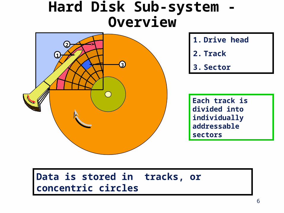
1. Drive head
2. Track
3. Sector
2
3
1
Hard Disk Sub-system - Overview
Data is stored in tracks, or concentric circles
Each track is divided into individually addressable sectors
7
Hard Disk Sub-system - Overview
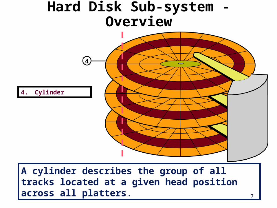
A cylinder describes the group of all tracks located at a given head position across all platters.
4. Cylinder
4
8
Hard Disk Sub-system: Head Hard drive heads contain an electromagnet and work
the same way as a tape recorder’s head.The head reads or writes magnetically encoded patterns
that represent digital data.» As disk rotates, a small current in the coil close to the disk
effectively creates a tiny permanent magnet on the disk.
See section on Floppy Disk Sub-system for more information on the reading and writing process.
There are twice as many heads as platters because data is stored on both sides of the platter. Sometimes one head is dedicated to internal drive servo
operations & these drives have an odd number of heads.
9
Hard Disk Sub-system: Head Hard drive heads are moved back and forth with a
“voice coil” actuator above the surface of the platter. The positioning of the heads from track to track by the
servo motor is called seeking.
The head is supported by a thin layer of air (forced in motion by the spin of the disk), which lifts it like an airplane wing.The read/write heads are designed to fly just a few
microinches above the surface of the platters. » This distance is less than the size of a particle of
smoke.
10
Hard Disk Sub-system: Head Hard drives use an electromechanical technique called
closed loop servo positioning to counter the effects of temperature variations, shock, & vibration.There are two primary servo head positioning techniques
that provide positional feedback to the drive electronics and ensure precise head alignment and positioning.
» Dedicated servo: Positioning information resides on a single dedicated platter surface accessed by a single dedicated head - to which the other heads are slaved. This requires one side of a platter not be used for data storage.
» Embedded servo intersperses the servo information with the data recorded on each of the tracks and the drive adjust the position of the heads so that they receive the maximum signal from prerecorded servo bursts.
11
Hard Disk Sub-system: Head The long life of a hard drive is due in part to the fact
that the heads do not contact the storage media.In a floppy drive, the read/write head does contact the
media, causing wear.
When the drive is powered down, the read/write heads touch down in a designated "landing zone".A safe place on the platter where no information is stored
If contamination or shock cause the heads to touch the surface, or "crash," the heads or data surface can be damaged and data lost. Today's drives are tightly sealed and built to withstand
shocks in the range of 70-100 Gs.

12
Hard Disk Sub-system: Tracks & Cylinders The area of the disk that passes under a single head
during one complete spin of the disk traces a circle.Data is recorded in a set of concentric circles called
cylinders or tracks.» The terms are often used interchangeably, but track
traditionally refers to a single ring on one side of a disk, and cylinder refers to a stack of tracks.
A cylinder is a stack of tracks at a given head position.» It represents a vertical view of the tracks in a drive.
Typically a hard disk drive will have from 306 to more than 4,800 cylinders.
Current disk drives have from 2,000 to 4,800 tracks per inch (TPI) on its recording surface.
13
Hard Disk Sub-system: Sector The data on each track is divided into equal size
pieces called sectors. Low-level formatting divides each track into sectors by
placing Address Marks & Sector ID headers around the track.The Sector ID contains the Cylinder, Head, & Sector
Number.
A sector is the smallest unit of data storage on a track.All sectors hold 512 bytes of data on a DOS PC.
» Other Operating Systems may use different size sectors
Only the 512 bytes of data in the data field are written to in normal operation.
14
Hard Disk Sub-system: Sector In earlier designs, the number of sectors that would fit
on the innermost track constrained the number of sectors per track for the entire platter.Near the outer edge of the disk, tracks are longer so
more sectors could fit.
Many modern drives use Multiple Zone Recording to pack more data onto the surface of the disk.By dividing the outer tracks into more sectors, data can
be packed uniformly throughout the surface of a platter, disk surface is used more efficiently.
» e.g. >60 sectors outside tracks; < 40 sectors inside tracks
Note: All tracks in the same zone have the same number of Sectors per Track.
15
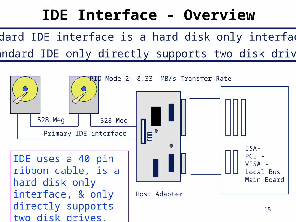
IDE Interface - Overview
528 Meg 528 Meg
Primary IDE interface
Host Adapter
ISA-PCI - VESA -Local BusMain Board
PIO Mode 2: 8.33 MB/s Transfer Rate
Standard IDE interface is a hard disk only interface.
Standard IDE only directly supports two disk drives.
IDE uses a 40 pin ribbon cable, is a hard disk only interface, & only directly supports two disk drives.
16
IDE Interface - Overview IDE stands for Integrated Drive Electronics (or
numerous other interpretations)Integrated Disk Electronics; Intelligent Drive (or Device)
Electronics; Inbuilt Drive Electronics
In 1986 Western Digital & Compaq Corp. worked together to build the hard drive controller into the hard drive itself (rather than on a controller card). The interface is integrated into the hard drive itself and
hence the name Integrated Drive Electronics (IDE). » IDE was developed from the ST506 interface (from Seagate
Technology)--the defacto standard for PC/AT hard drives.
Seagate used the name ATA (Advanced Technology Attachment) to describe their version of the IDE interface.

17
IDE Interface - Overview IDE interface is based on the "AT bus" (16 bit ISA bus)
IDE combines the drive and controller, and a single cable connects the unit directly to the PC bus.
» The physical connection is a “host adapter” which connects the PC system board to the IDE drives.
IDE’s intelligence resides in the drive electronic components & typically consists of the following:Disk Controller; Buffer RAM (~128K SRAM); Servo
Controller; Data Separator; Frequency Synthesizer; Data Encoder/Decoder; Microcontroller; Pulse Detector; Spindle Motor Driver; Actuator Driver; and Head Disk Assy (Disks, heads, actuator, & spindle).
18
IDE Interface - Overview IDE drives are Low Level formatted at the factory to
create the cylinder, sector & side data.High level formatting sets up the O/S file system
structure (boot record, FAT, directory, etc.)IDE drives have only a logical appearance to the AT, so
a standard low-level-format utility may not work correctly and may damage an IDE drive.
Most IDE drives incorporate automatic bad-sector remapping. If it detects failed attempts to read data but eventually
gets a good data access, it automatically remaps the bad sector using sectors reserved for this purpose.
19
IDE Data Transfers Programmed Input/Output (PIO) is the traditional
method used to transfer IDE data.The PC/XT used DMA to support disk data transfers, due
to PC/XT DMA being faster than 4.77 MHz CPU PIO. With the advent of the PC/AT, the CPU PIO speed
increased (80286 at 8.0 MHz), while the DMA speed was the same as in the PC/XT (2 MB/s).
» So, the PC/AT hard disk controller used PIO data transfers because PC/AT PIO was now faster than DMA.
As IDE evolved from this original PC/AT hard disk controller, it too supported PIO data transfers.
» The INT 13h BIOS and O/S devices drivers have continued to support PIO data transfer capabilities.
20
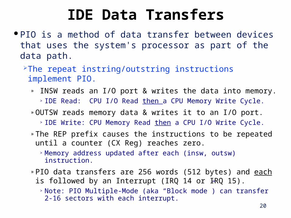
IDE Data Transfers PIO is a method of data transfer between devices that
uses the system's processor as part of the data path. The repeat instring/outstring instructions implement PIO.
» INSW reads an I/O port & writes the data into memory. > IDE Read: CPU I/O Read then a CPU Memory Write Cycle.
» OUTSW reads memory data & writes it to an I/O port. > IDE Write: CPU Memory Read then a CPU I/O Write Cycle.
» The REP prefix causes the instructions to be repeated until a counter (CX Reg) reaches zero.
> Memory address updated after each (insw, outsw) instruction.
» PIO data transfers are 256 words (512 bytes) and each is followed by an Interrupt (IRQ 14 or IRQ 15).
> Note: PIO Multiple-Mode (aka “Block mode”) can transfer 2-16 sectors with each interrupt.
21
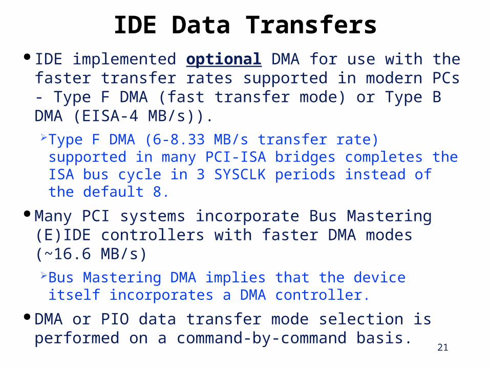
IDE Data Transfers IDE implemented optional DMA for use with the faster
transfer rates supported in modern PCs - Type F DMA (fast transfer mode) or Type B DMA (EISA-4 MB/s)). Type F DMA (6-8.33 MB/s transfer rate) supported in
many PCI-ISA bridges completes the ISA bus cycle in 3 SYSCLK periods instead of the default 8.
Many PCI systems incorporate Bus Mastering (E)IDE controllers with faster DMA modes (~16.6 MB/s) Bus Mastering DMA implies that the device itself
incorporates a DMA controller.
DMA or PIO data transfer mode selection is performed on a command-by-command basis.

22
IDE - The 528 Meg BarrierBIOS INT 13h level: Logical CHS - 1024 cylinders max
» 10 bits-cyl # 8 bits-head # 6 bits-sector #
» Cyl max 1024 Heads max 256 SPT max 63
IDE I/F level: Physical CHS - 16 heads maximum » 16 bits-cyl # 4 bits-head # 8 bits-sector #
» Cyl max 65,536 Heads max 16 SPT max 255
The combination (smaller of each) of the number of bits at the INT 13h & at the IDE interface levels produce an artificial 528 Meg barrier. (Note: One sector is 512 bytes)
» 10 bits-cyl # 4 bits-head # 6 bits-sector #
» Cyl max 1024 Heads max 16 SPT max 63
» (1024 * 16 * 63) or 1, 032,192 (~220) data sectors or
» (1024 * 16 * 63 * 512) or 528,482,304 bytes (504 MB)
23
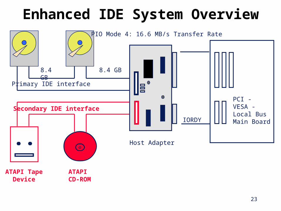
8.4 GB 8.4 GB
Primary IDE interface
Secondary IDE interface
ATAPI TapeDevice
ATAPI CD-ROM
Host Adapter
IORDY
PCI - VESA -Local BusMain Board
PIO Mode 4: 16.6 MB/s Transfer Rate
Enhanced IDE System Overview
24
Enhanced IDE (EIDE) The Enhanced IDE (EIDE) or Fast ATA standard
overcomes the 528 Meg limit, provides faster data transfer rates and allows for the connection of CD-ROM and Tape Backup drives. Full backward compatibility to ATA IDE.
EIDE attempts to combine the flexibility and speed of SCSI with the simplicity, industry compatibility, and low connection costs of traditional IDE.EIDE was a joint effort by hard disk manufacturers to
avoid an industry move to the extensive use of SCSI as a hard drive interface.
Systems with EIDE were generally available in 1995.
25
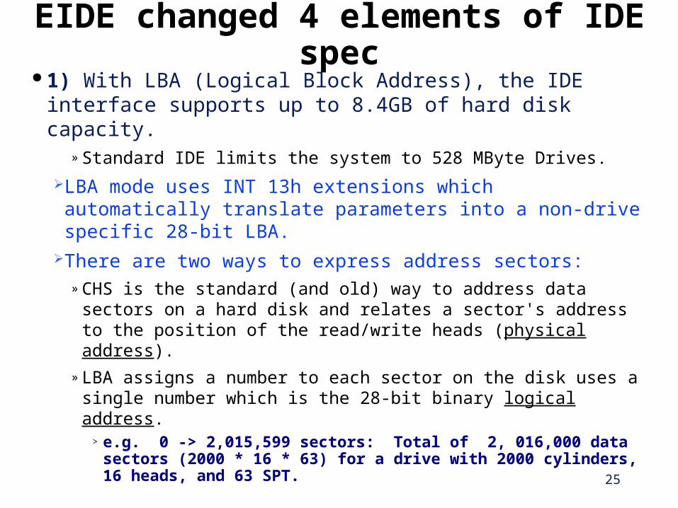
EIDE changed 4 elements of IDE spec 1) With LBA (Logical Block Address), the IDE interface
supports up to 8.4GB of hard disk capacity.» Standard IDE limits the system to 528 MByte Drives.
LBA mode uses INT 13h extensions which automatically translate parameters into a non-drive specific 28-bit LBA.
There are two ways to express address sectors:» CHS is the standard (and old) way to address data sectors
on a hard disk and relates a sector's address to the position of the read/write heads (physical address).
» LBA assigns a number to each sector on the disk uses a single number which is the 28-bit binary logical address.
> e.g. 0 -> 2,015,599 sectors: Total of 2, 016,000 data sectors (2000 * 16 * 63) for a drive with 2000 cylinders, 16 heads, and 63 SPT.

26
EIDE changed 4 elements of IDE spec 2) Mode 4 PIO & Multiword DMA mode 2 allow data
transfer rates with EIDE drives as high as 16MB/s.» IDE limited to 8.33 MB/sec by ISA bus timing restrictions.
Mode 3 & 4 PIO use hardware handshaking (throttling) between the host & drive via the IORDY (buffered ISA IOCHRDY) signal for increased host-transfer rates.
» When the drive de-asserts the IORDY signal, the host extends the read/write cycle until IORDY is asserted.
» Note: Transfers that do not use throttling (blind transfers) have slower transfer rates based on the worst case conditions.
DMA or PIO data transfer mode selection is performed on a command-by-command basis.

27
EIDE changed 4 elements of IDE spec 2) Increased host-transfer rates (Cont.)
Possible transfer rates of the IDE bus (ATA or ATA-1)Single word DMA 0 2.1 MBytes/s
PIO mode 0 (4.77 MHz PC) 3.33 MBytes/s
Single word DMA 1, Multi word DMA 0 4.16 MBytes/s
PIO mode 1 (6 MHz PC) 5.22 MBytes/s
PIO mode 2 (8 MHz PC), Single word DMA 2 8.33 MBytes/s
Possible transfer rates of the EIDE bus (Fast ATA or ATA-2 )PIO mode 3 (Requires IORDY throttling) 11.1 MBytes/s
Multi word DMA Mode 1 13.3 MBytes/s
PIO mode 4, Multi word DMA Mode 2 16.6 MBytes/s - 1994
Possible transfer rates of Ultra-ATA (Ultra DMA/33 or fast ATA-3)Multi word DMA 3 -Proposed Future Standard (Uses both transitions of clock)
33.3 MBytes/s - 1997
28
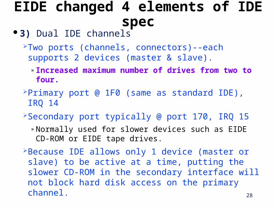
EIDE changed 4 elements of IDE spec 3) Dual IDE channels
Two ports (channels, connectors)--each supports 2 devices (master & slave).
» Increased maximum number of drives from two to four.
Primary port @ 1F0 (same as standard IDE), IRQ 14Secondary port typically @ port 170, IRQ 15
» Normally used for slower devices such as EIDE CD-ROM or EIDE tape drives.
Because IDE allows only 1 device (master or slave) to be active at a time, putting the slower CD-ROM in the secondary interface will not block hard disk access on the primary channel.
29
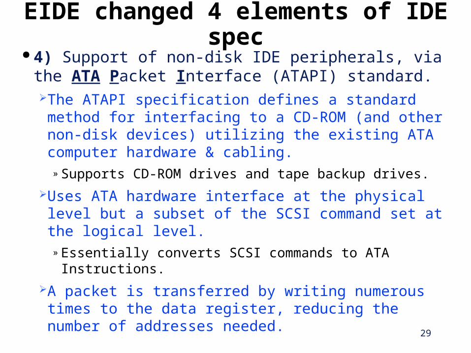
EIDE changed 4 elements of IDE spec 4) Support of non-disk IDE peripherals, via the ATA
Packet Interface (ATAPI) standard. The ATAPI specification defines a standard method for
interfacing to a CD-ROM (and other non-disk devices) utilizing the existing ATA computer hardware & cabling.
» Supports CD-ROM drives and tape backup drives.
Uses ATA hardware interface at the physical level but a subset of the SCSI command set at the logical level.
» Essentially converts SCSI commands to ATA Instructions.
A packet is transferred by writing numerous times to the data register, reducing the number of addresses needed.
30
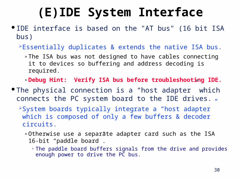
(E)IDE System Interface IDE interface is based on the "AT bus" (16 bit ISA bus)
Essentially duplicates & extends the native ISA bus.» The ISA bus was not designed to have cables connecting it
to devices so buffering and address decoding is required.
» Debug Hint: Verify ISA bus before troubleshooting IDE.
The physical connection is a “host adapter” which connects the PC system board to the IDE drives.System boards typically integrate a “host adapter” which
is composed of only a few buffers & decoder circuits.» Otherwise use a separate adapter card such as the ISA 16-
bit “paddle board”.> The paddle board buffers signals from the drive and provides
enough power to drive the PC bus.
31
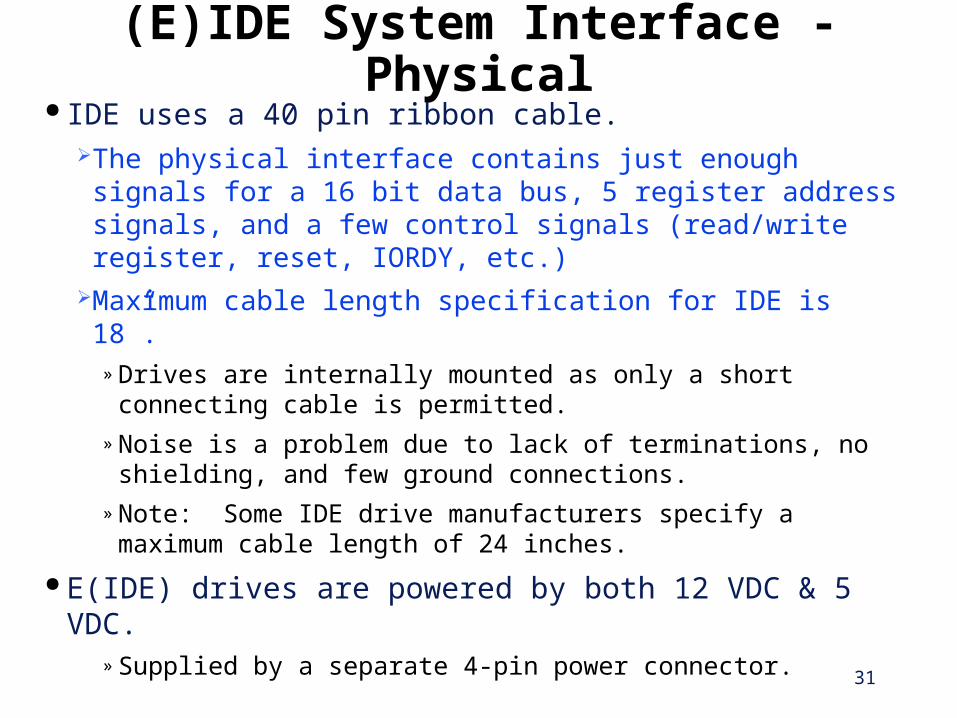
(E)IDE System Interface - Physical IDE uses a 40 pin ribbon cable.
The physical interface contains just enough signals for a 16 bit data bus, 5 register address signals, and a few control signals (read/write register, reset, IORDY, etc.)
Maximum cable length specification for IDE is 18”.» Drives are internally mounted as only a short connecting
cable is permitted.
» Noise is a problem due to lack of terminations, no shielding, and few ground connections.
» Note: Some IDE drive manufacturers specify a maximum cable length of 24 inches.
E(IDE) drives are powered by both 12 VDC & 5 VDC.» Supplied by a separate 4-pin power connector.

32
(E)IDE System Interface - Physical Pin Assignment Pin Assignment1 -Reset (Host) 2 GND3 Data 7 (In/Out) 4 Data 8 (In/Out)5 Data 6 (In/Out) 6 Data 9 (In/Out)7 Data 5 (In/Out) 8 Data 10 (In/Out)9 Data 4 (In/Out) 10 Data 11 (In/Out)11 Data 3 (In/Out) 12 Data 12 (In/Out)13 Data 2 (In/Out) 14 Data 13 (In/Out)15 Data 1 (In/Out) 16 Data 14 (In/Out)17 Data 0 (In/Out) 18 Data 15 (In/Out)19 GND 20 Key21 DDMARQ (Drive) 22 GND23 -DIOW (Host) 24 GND25 -DIOR (Host) 26 GND27 IORDY (Drive) 28 SPSYNC:CSEL29 -DDAK (Host) 30 GND31 INTRQ (Drive) 32 -IOCS16 (Drive)33 DA1 [Addr 1](Host) 34 -PDIAG35 DA0 [Addr 0](Host) 36 DA2 [Addr 2](Host)37 -CS1FX [1F0-1F7](Host) 38 -CS3FX [3f6-3f7](Host)39 -DASP (Drive) 40 GND
The ONLY IDE signals that do not correspond directly to PC/AT I/O signals are:
CS1FX-, CS3FX-, SPSYNC:CSEL, DASP-, & PDIAG-
33
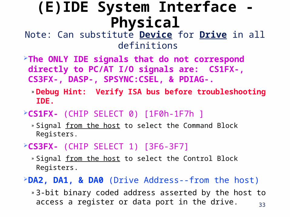
(E)IDE System Interface - PhysicalNote: Can substitute Device for Drive in all definitions
The ONLY IDE signals that do not correspond directly to PC/AT I/O signals are: CS1FX-, CS3FX-, DASP-, SPSYNC:CSEL, & PDIAG-.
» Debug Hint: Verify ISA bus before troubleshooting IDE.
CS1FX- (CHIP SELECT 0) [1F0h-1F7h ]» Signal from the host to select the Command Block Registers.
CS3FX- (CHIP SELECT 1) [3F6-3F7]» Signal from the host to select the Control Block Registers.
DA2, DA1, & DA0 (Drive Address--from the host) » 3-bit binary coded address asserted by the host to access a
register or data port in the drive.

34
(E)IDE System Interface - PhysicalDASP- (Drive Active, Slave [Device 1] Present)
» Used for illumination of drive-activity LED
» During initialization slave informs master of presence.
DD0-DD15 (Drive Data)» Bi-directional data interface between the host & the drive .
DIOR- (Drive I/O read--from the host )» Enables data from the drive onto DD0-DD7 or DD0-DD15.
DIOW- (Drive I/O write--from the host )» Latches data from system into a register of the drive .
DMACK- (DMA acknowledge--from the host ) (Optional)» Host uses in response to DMARQ to initiate DMA transfers.
35
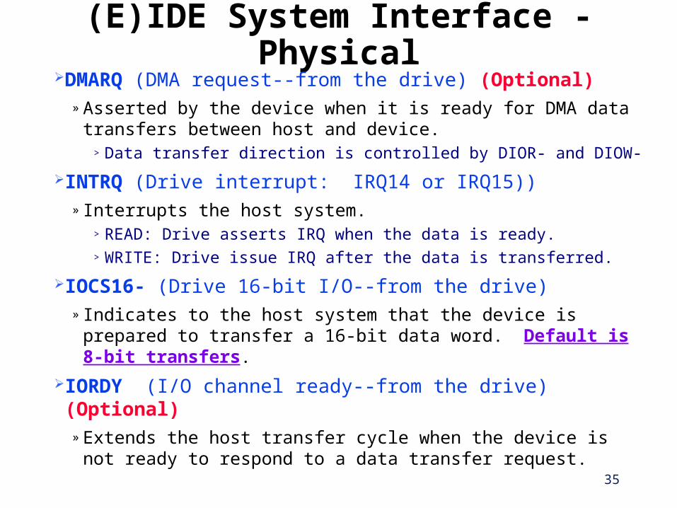
(E)IDE System Interface - PhysicalDMARQ (DMA request--from the drive) (Optional)
» Asserted by the device when it is ready for DMA data transfers between host and device.
> Data transfer direction is controlled by DIOR- and DIOW-
INTRQ (Drive interrupt: IRQ14 or IRQ15))» Interrupts the host system.
> READ: Drive asserts IRQ when the data is ready. > WRITE: Drive issue IRQ after the data is transferred.
IOCS16- (Drive 16-bit I/O--from the drive)» Indicates to the host system that the device is prepared to
transfer a 16-bit data word. Default is 8-bit transfers.
IORDY (I/O channel ready--from the drive) (Optional)» Extends the host transfer cycle when the device is not ready
to respond to a data transfer request.
36
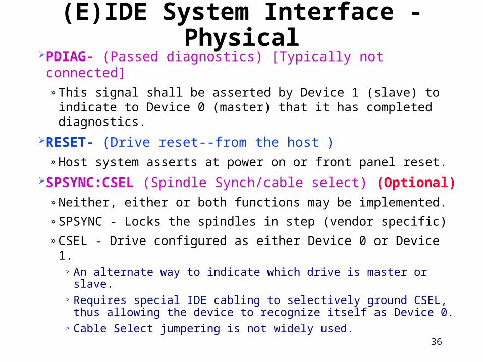
(E)IDE System Interface - PhysicalPDIAG- (Passed diagnostics) [Typically not connected]
» This signal shall be asserted by Device 1 (slave) to indicate to Device 0 (master) that it has completed diagnostics.
RESET- (Drive reset--from the host )» Host system asserts at power on or front panel reset.
SPSYNC:CSEL (Spindle Synch/cable select) (Optional)» Neither, either or both functions may be implemented.
» SPSYNC - Locks the spindles in step (vendor specific)
» CSEL - Drive configured as either Device 0 or Device 1.> An alternate way to indicate which drive is master or slave.> Requires special IDE cabling to selectively ground CSEL, thus
allowing the device to recognize itself as Device 0.> Cable Select jumpering is not widely used.
37
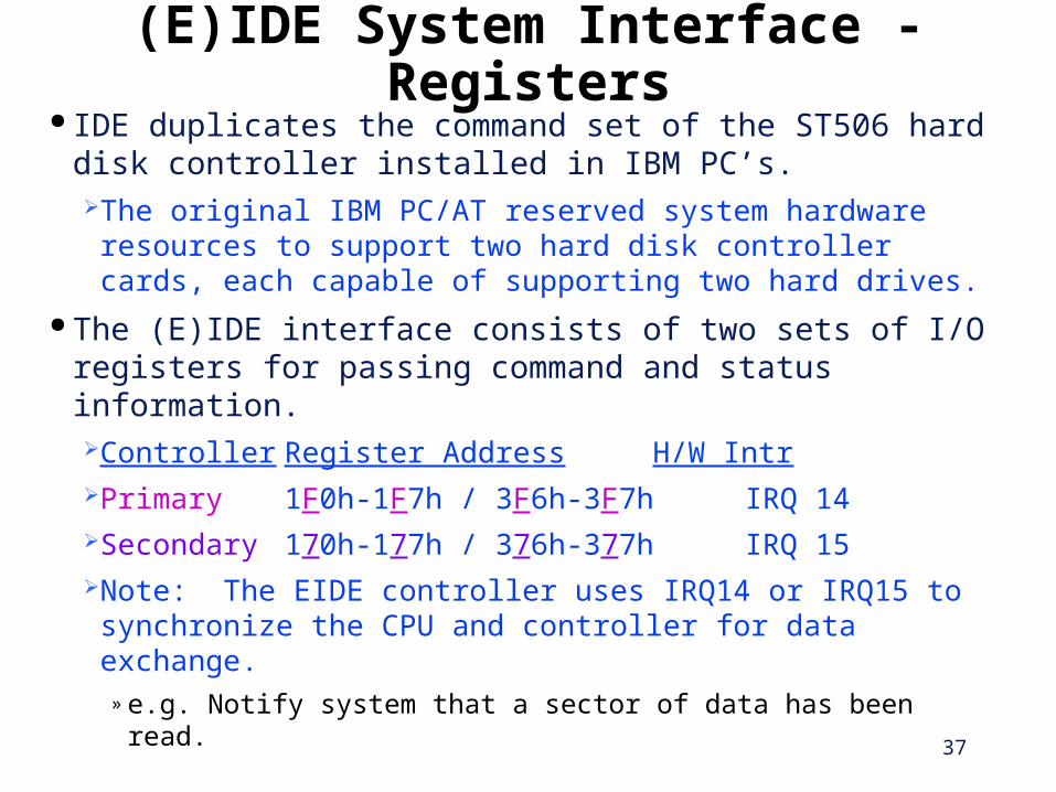
(E)IDE System Interface - Registers IDE duplicates the command set of the ST506 hard
disk controller installed in IBM PC’s. The original IBM PC/AT reserved system hardware
resources to support two hard disk controller cards, each capable of supporting two hard drives.
The (E)IDE interface consists of two sets of I/O registers for passing command and status information.Controller Register Address H/W IntrPrimary 1F0h-1F7h / 3F6h-3F7h IRQ 14Secondary 170h-177h / 376h-377h IRQ 15Note: The EIDE controller uses IRQ14 or IRQ15 to
synchronize the CPU and controller for data exchange.» e.g. Notify system that a sector of data has been read.

38
(E)IDE System Interface - Registers The host addresses the drive with programmed I/O.
A3...A9 generate chip selects CS1FX- and CS3FX-.DA2:0 for register selection within each decode region.
The IDE controller is accessed by means of data & control registers commonly called the “AT task file”.
+----+------+------+---+---+---+----------------+
|Addr|-CS1FX|-CS3FX|DA2|DA1|DA0| Description |(1FX Not Listed) +----+------+------+---+---+---+----------------+-----------+|3F6 | 1 | 0 | 1 | 1 | 0 | Device Control | Control | |3F7 | 1 | 0 | 1 | 1 | 1 | Drive Address | Block Regs|+----+------+------+---+---+---+----------------+-----------+|1F0 | 0 | 1 | 0 | 0 | 0 | Data Port | <--+ ||1F1 | 0 | 1 | 0 | 0 | 1 | Error/Precomp | | ||1F2 | 0 | 1 | 0 | 1 | 0 | Sector Count | Command ||1F3 | 0 | 1 | 0 | 1 | 1 | Sector Number | Block ||1F4 | 0 | 1 | 1 | 0 | 0 | Cylinder Low | Registers ||1F5 | 0 | 1 | 1 | 0 | 1 | Cylinder High | | ||1F6 | 0 | 1 | 1 | 1 | 0 | Drive / Head | | ||1F7 | 0 | 1 | 1 | 1 | 1 | Status/Command | <--+ |+----+------+------+---+---+---+----------------+-----------+

39
(E)IDE System Interface - Registers Chip Select signals are generated as follows with IDE
Drives on both Primary & Secondary connectors:» Note: Both drives jumpered as MASTER.
Primary IDE Connector Chip Selects.» Pin 37 - CS1P#:1FX Primary Cmd Regs
> Read Port 1F6 [ITP - “port (1f6)”]
» Pin 38 - CS3P#: 3FX Primary Control Regs > Read Port 3F6 [ITP - “port (3f6)”]
Secondary IDE Connector Chip Selects.» Pin 37 - CS1S#: 17X Secondary Cmd Regs
> Read Port 176 [ITP - “port (176)”]
» Pin 38 - CS3S#: 37X Secondary Control Regs > Read Port 376 [ITP - “port (376)”]

40
(E)IDE System Interface - Registers Technicians may find the following registers useful:
WARNING: Some commands sent directly to the IDE Controller can corrupt data on the drive.
» Note: Detailed IDE register description and programming is beyond the scope of this course.
Port 1F0 ( Read/Write): DATA PORT REGISTERAll data transferred passes through this register.The ONLY 16 bit register (other registers are 8-bit)
» INSW reads the I/O port & writes the data into memory.
» OUTSW reads memory data & writes it to the I/O port.
Note: Port 3F7 is shared with the diskette controllerDiskette controller returns “disk changed” state on bit 7.
41
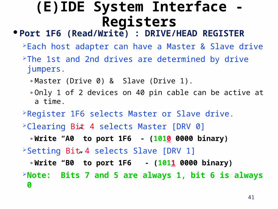
(E)IDE System Interface - Registers Port 1F6 (Read/Write) : DRIVE/HEAD REGISTER
Each host adapter can have a Master & Slave driveThe 1st and 2nd drives are determined by drive jumpers.
» Master (Drive 0) & Slave (Drive 1).
» Only 1 of 2 devices on 40 pin cable can be active at a time.
Register 1F6 selects Master or Slave drive.Clearing Bit 4 selects Master [DRV 0]
» Write “A0” to port 1F6 - (1010 0000 binary)
Setting Bit 4 selects Slave [DRV 1]» Write “B0” to port 1F6 - (1011 0000 binary)
Note: Bits 7 and 5 are always 1, bit 6 is always 0
42
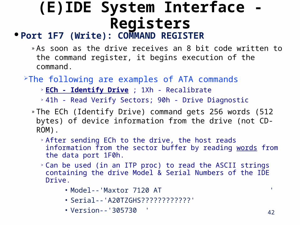
(E)IDE System Interface - Registers Port 1F7 (Write): COMMAND REGISTER
» As soon as the drive receives an 8 bit code written to the command register, it begins execution of the command.
The following are examples of ATA commands> ECh - Identify Drive ; 1Xh - Recalibrate > 41h - Read Verify Sectors; 90h - Drive Diagnostic
» The ECh (Identify Drive) command gets 256 words (512 bytes) of device information from the drive (not CD-ROM).
> After sending ECh to the drive, the host reads information from the sector buffer by reading words from the data port 1F0h.
> Can be used (in an ITP proc) to read the ASCII strings containing the drive Model & Serial Numbers of the IDE Drive.
• Model--'Maxtor 7120 AT '
• Serial--'A20TZGHS????????????'
• Version--'305730 '
43
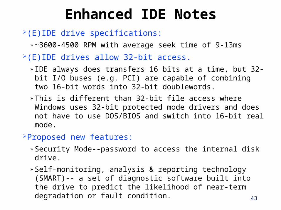
Enhanced IDE Notes(E)IDE drive specifications:
» ~3600-4500 RPM with average seek time of 9-13ms
(E)IDE drives allow 32-bit access.» IDE always does transfers 16 bits at a time, but 32-bit I/O
buses (e.g. PCI) are capable of combining two 16-bit words into 32-bit doublewords.
» This is different than 32-bit file access where Windows uses 32-bit protected mode drivers and does not have to use DOS/BIOS and switch into 16-bit real mode.
Proposed new features:» Security Mode--password to access the internal disk drive.
» Self-monitoring, analysis & reporting technology (SMART)-- a set of diagnostic software built into the drive to predict the likelihood of near-term degradation or fault condition.

44
Hard Disk BIOS Support INT 13h invokes BIOS Fixed Disk & diskette Service.
The INT 13h Hard Disk Service interface provides access to the disk drives supported by the system.
» Note: If a fixed disk is present, the BIOS automatically redirects all INT 13h Diskette Request services to INT 40h.
> This is transparent to the user & users should continue to invoke INT 13 for both diskette and fixed disk services.
BIOS interrupts may be used in ITP debug procs to read, write, and verify hard drive operation.
» INT 13h will program the disk controller registers and execute the required operation (e.g. read sector).
» The data from the hard disk sector can then be viewed in system memory using the ITP debug tool.
45
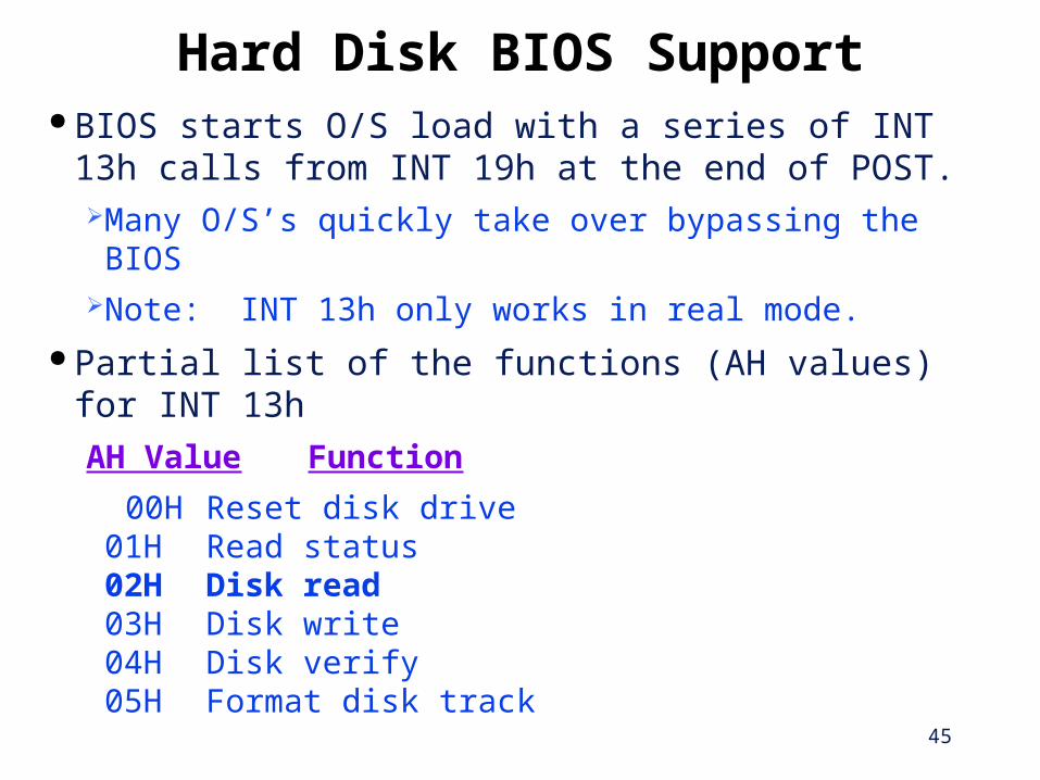
Hard Disk BIOS Support BIOS starts O/S load with a series of INT 13h calls
from INT 19h at the end of POST. Many O/S’s quickly take over bypassing the BIOSNote: INT 13h only works in real mode.
Partial list of the functions (AH values) for INT 13h
AH Value Function
00H Reset disk drive01H Read status02H Disk read03H Disk write04H Disk verify05H Format disk track
46
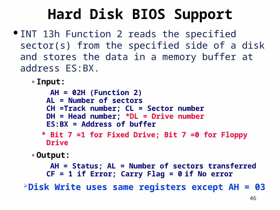
Hard Disk BIOS Support INT 13h Function 2 reads the specified sector(s) from
the specified side of a disk and stores the data in a memory buffer at address ES:BX.
» Input: AH = 02H (Function 2)
AL = Number of sectorsCH =Track number; CL = Sector numberDH = Head number; *DL = Drive numberES:BX = Address of buffer
* Bit 7 =1 for Fixed Drive; Bit 7 =0 for Floppy Drive
» Output: AH = Status; AL = Number of sectors transferred
CF = 1 if Error; Carry Flag = 0 if No error
Disk Write uses same registers except AH = 03
47
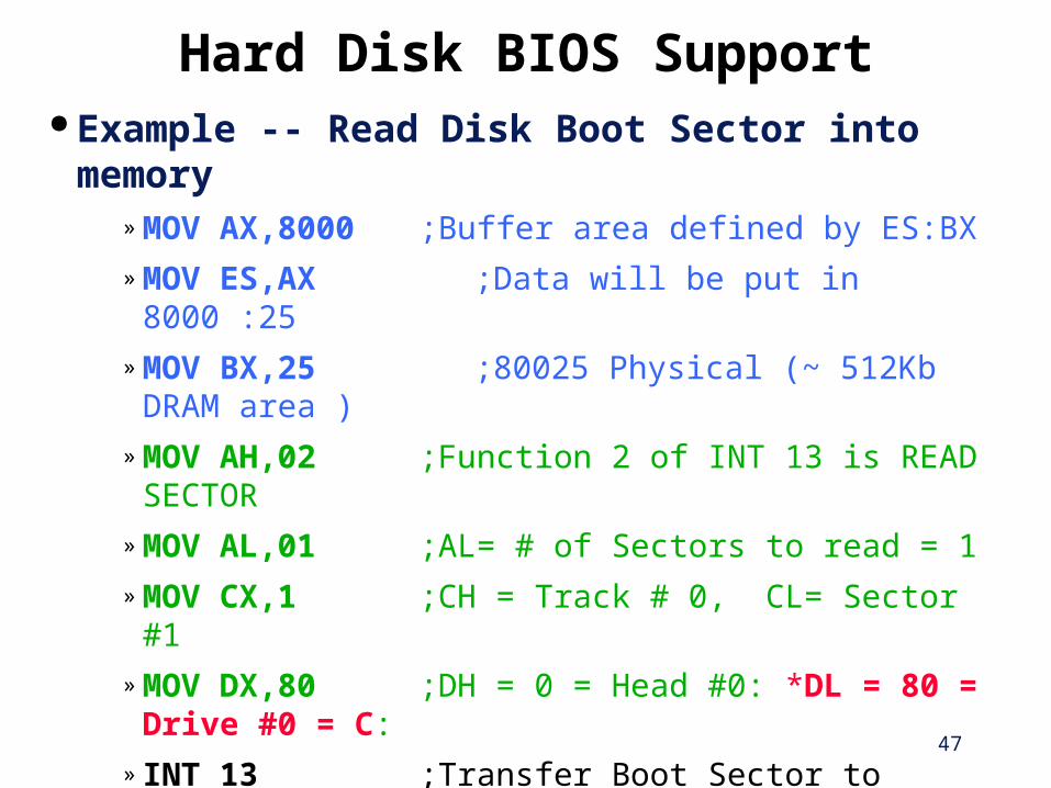
Example -- Read Disk Boot Sector into memory» MOV AX,8000 ;Buffer area defined by ES:BX
» MOV ES,AX ;Data will be put in 8000 :25
» MOV BX,25 ;80025 Physical (~ 512Kb DRAM area )
» MOV AH,02 ;Function 2 of INT 13 is READ SECTOR
» MOV AL,01 ;AL= # of Sectors to read = 1
» MOV CX,1 ;CH = Track # 0, CL= Sector #1
» MOV DX,80 ;DH = 0 = Head #0: *DL = 80 = Drive #0 = C:
» INT 13 ;Transfer Boot Sector to 8000:25
*Note: DL= 80 for Hard Drv #0; DL = 0 for Floppy Drv #0
Hard Disk BIOS Support

48
REVIEW & SUMMARYWE HAVE DISCUSSED THE FOLLOWING:
The components of the Hard Disk Sub-system.Electromechanical devices with rigid platters that rotate
faster & store data at a higher density than floppy disks.Hard drive heads are moved with a “voice coil” actuator &
fly just a few microinches above the platters surface. Data is recorded in a set of concentric circles called
cylinders--a stack of tracks at a given head position. The features of the IDE & EIDE Interface.
The interface is integrated into the hard drive itself. IDE interface is based on the "AT bus" (16 bit ISA bus).EIDE overcomes 528 Meg limit, has faster transfer rates
& allows for CD-ROM & Tape Backup drives.

49
REVIEW & SUMMARY (E)IDE data transfers using Programmed I/O.
PIO is the traditional method used to transfer IDE data.» Optional DMA for use with the faster transfer rates.
The repeat instring/outstring instructions implement PIO.» INSW reads an I/O port & writes the data into memory.
» OUTSW reads memory data & writes it to an I/O port.
The (E)IDE Disk Drive interface cables.40 pin ribbon cable: 16 bit data, 5 addr, & a few control.
» Maximum cable length specification for IDE is 18”.
Debug Hint: Verify ISA bus before troubleshooting IDE.» CS1FX, CS3FX, DASP, SPSYNC:CSEL, & PDIAG are the
only signals that do not correspond directly to ISA signals
50
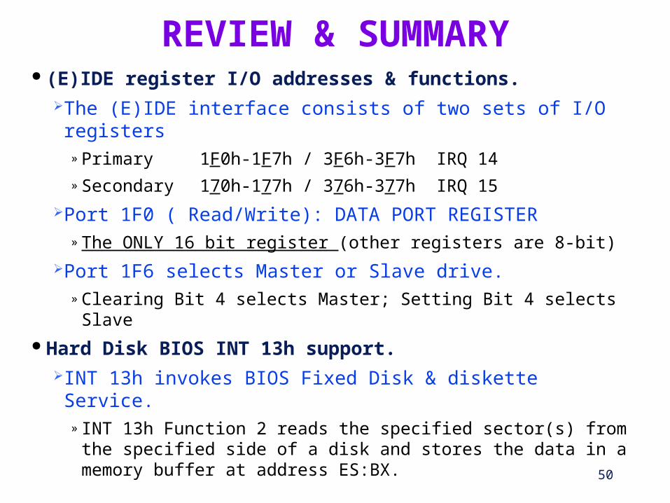
REVIEW & SUMMARY (E)IDE register I/O addresses & functions.
The (E)IDE interface consists of two sets of I/O registers» Primary 1F0h-1F7h / 3F6h-3F7h IRQ 14
» Secondary 170h-177h / 376h-377h IRQ 15
Port 1F0 ( Read/Write): DATA PORT REGISTER» The ONLY 16 bit register (other registers are 8-bit)
Port 1F6 selects Master or Slave drive.» Clearing Bit 4 selects Master; Setting Bit 4 selects Slave
Hard Disk BIOS INT 13h support.INT 13h invokes BIOS Fixed Disk & diskette Service.
» INT 13h Function 2 reads the specified sector(s) from the specified side of a disk and stores the data in a memory buffer at address ES:BX.
51
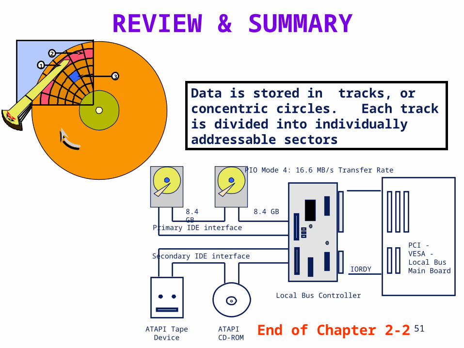
REVIEW & SUMMARY
8.4 GB 8.4 GB
Primary IDE interface
Secondary IDE interface
ATAPI TapeDevice
ATAPI CD-ROM
Local Bus Controller
IORDY
PCI - VESA -Local BusMain Board
PIO Mode 4: 16.6 MB/s Transfer Rate
2
3
1
Data is stored in tracks, or concentric circles. Each track is divided into individually addressable sectors
End of Chapter 2-2