1. physical quantities and units 1.4 scalar and vector · p2 o= r p−1 2 p2 o=1 2 ( q+ r) p r2=...
TRANSCRIPT
Page 3 of 15
1. PHYSICAL QUANTITIES AND UNITS
1.1 Physical Quantities A physical quantity is made up of magnitude and unit
1.2 Base Units The following are base units:
Quantity Basic Unit
Name Symbol Name Symbol
Mass 𝑚 Kilogram 𝑘𝑔 Length 𝑙 Meter 𝑚 Time 𝑡 Second 𝑠 Temperature 𝑇 Kelvin 𝐾 Electric Current 𝐼 Ampere 𝐴
All units (not above) can be broken down to base units
Homogeneity can be used to prove equations.
An equation is homogenous if base units on left hand
side are the same as base units on right hand side.
This may not work every time due to the fact that it does
not take pure numbers into account (𝐸𝑘 formula)
1.3 Multiples and Submultiples Multiple Prefix Symbol
1012 Tera 𝑇 109 Giga 𝐺 106 Mega 𝑀 103 Kilo 𝑘
Submultiple Prefix Symbol
10-3 Milli 𝑚 10-6 Micro 𝜇 10-9 Nano 𝑛 10-12 Pico 𝑝
1.4 Estimations Mass of a person 70 kg
Height of a person 1.5 m
Walking speed 1 ms-1
Speed of a car on the motorway 30 ms-1
Volume of a can of a drink 300 cm3
Density of water 1000 kgm-3
Density of air 1 kgm-3
Weight of an apple 1 N
Current in a domestic appliance 13 A
e.m.f of a car battery 12 V
Hearing range 20 Hz to 20,000 Hz
Young’s Modulus of a material Something × 1011
1.4 Scalar and Vector
Scalar: has magnitude only, cannot be –ve
e.g. speed, energy, power, work, mass, distance
Vector: has magnitude and direction, can be –ve
e.g. displacement, acceleration, force, velocity
momentum, weight, electric field strength
1.5 Vectors
2. MEASUREMENT TECHNIQUES Quantity Accuracy Instrument
Length
1 cm Tape
0.1 cm Ruler
0.01 cm Vernier caliper
0.001 cm Micrometer screw gauge
Volume 1 cm3 Measuring cylinder
0.05 cm3 Pipette/burette
Angle 0.5o Protractor
Time
1 min Clocks
0.01 sec Stopwatch
𝑥-axis scale Time base of c.r.o
Temperature 1oC Thermometer
0.5oC Thermocouple
P.d. 0.01 V Voltmeter
Current 0.01 A Ammeter
0.0001 A Galvanometer
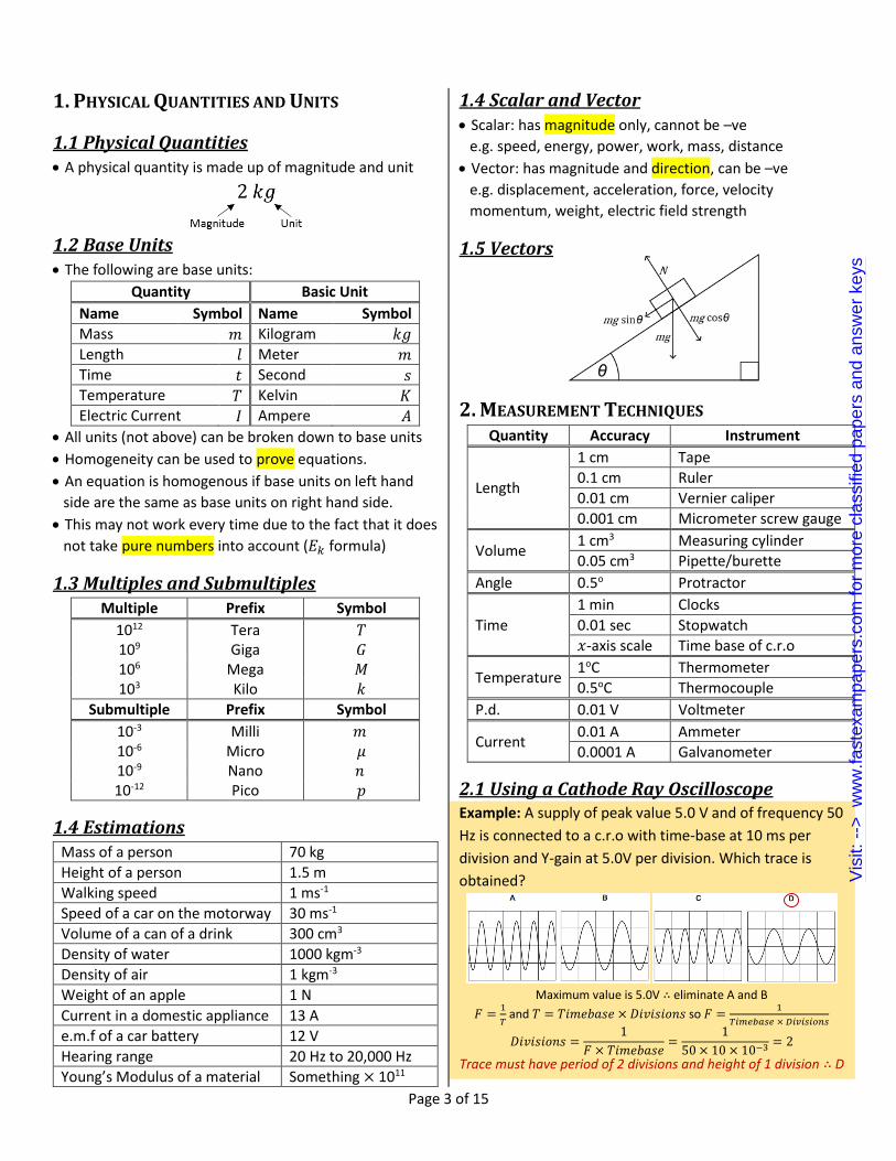
2.1 Using a Cathode Ray Oscilloscope Example: A supply of peak value 5.0 V and of frequency 50
Hz is connected to a c.r.o with time-base at 10 ms per
division and Y-gain at 5.0V per division. Which trace is
obtained?
Maximum value is 5.0V ∴ eliminate A and B
𝐹 =1
𝑇 and 𝑇 = 𝑇𝑖𝑚𝑒𝑏𝑎𝑠𝑒 × 𝐷𝑖𝑣𝑖𝑠𝑖𝑜𝑛𝑠 so 𝐹 =
1
𝑇𝑖𝑚𝑒𝑏𝑎𝑠𝑒 × 𝐷𝑖𝑣𝑖𝑠𝑖𝑜𝑛𝑠
𝐷𝑖𝑣𝑖𝑠𝑖𝑜𝑛𝑠 =1
𝐹 × 𝑇𝑖𝑚𝑒𝑏𝑎𝑠𝑒=
1
50 × 10 × 10−3 = 2
Trace must have period of 2 divisions and height of 1 division ∴ D
Vis
it: -
-> w
ww
.fast
exam
pape
rs.c
om fo
r m
ore
clas
sifie
d pa
pers
and
ans
wer
key
s

Page 4 of 15
2.1 Systematic and Random Errors
Systematic error:
o Constant error in one direction; too big or too small
o Cannot be eliminated by repeating or averaging
o If systematic error small, measurement accurate
o Accuracy: refers to degree of agreement between
result of a measurement and true value of quantity.
Random error:
o Random fluctuations or scatter about a true value
o Can be reduced by repeating and averaging
o When random error small, measurement precise
o Precision: refers to degree of agreement of repeated
measurements of the same quantity (regardless of
whether it is correct or not)
2.1 Calculations Involving Errors For a quantity 𝑥 = (2.0 ± 0.1)𝑚𝑚
Absolute uncertainty = ∆𝑥 = ±0.1𝑚𝑚
Fractional uncertainty =∆𝑥
𝑥= 0.05
Percentage uncertainty = ∆𝑥
𝑥× 100% = 5%
Combining errors:
o When values added or subtracted, add absolute error
If 𝑝 =2𝑥+𝑦
3 or 𝑝 =
2𝑥−𝑦
3, then ∆𝑝 =
2∆𝑥+∆𝑦
3
o When values multiplied or divided, add % errors
o When values are powered (e.g. squared), multiply
percentage error with power
If 𝑟 = 2𝑥𝑦3 or 𝑟 =2𝑥
𝑦3, then ∆𝑟
𝑟=
∆𝑥
𝑥+
3∆𝑦
𝑦
2.3 Treatment of Significant Figures
Actual error: recorded to only 1 significant figure
Number of decimal places for a calculated quantity is
equal to number of decimal places in actual error.
During a practical, when calculating using a measured
quantity, give answers to the same significant figure as
the measurement or one less
2.4 Micrometer Screw Gauge
Measures objects up to 0.01mm
Place object between anvil & spindle
Rotate thimble until object firmly held by jaws
Add together value from main scale and rotating scale
2.5 Vernier Scale Measures objects up to 0.1mm
Place object on rule
Push slide scale to edge of object.
The sliding scale is 0.9mm long & is
divided into 10 equal divisions.
Check which line division on sliding scale
matches with a line division on rule
Subtract the value from the sliding scale
(0.09 × 𝐷𝑖𝑣𝑖𝑠𝑖𝑜𝑛𝑠) by the value from the rule.
3. KINEMATICS
3.1 Linear Motion Distance: total length moved irrespective of direction
Displacement: distance in a certain direction
Speed: distance traveled per unit time, no direction
Velocity: the rate of change of displacement
Acceleration: the rate of change of velocity
Displacement-time graph:
o Gradient = velocity
3.2 Non-linear Motion Velocity-time graph:
o Gradient = acceleration
o Area under graph = change in displacement
Vis
it: -
-> w
ww
.fast
exam
pape
rs.c
om fo
r m
ore
clas
sifie
d pa
pers
and
ans
wer
key
s

Page 5 of 15
Uniform acceleration and straight line motion equations:
𝑣 = 𝑢 + 𝑎𝑡
𝑠 = 𝑢𝑡 +1
2𝑎𝑡2 𝑠 = 𝑣𝑡 −
1
2𝑎𝑡2
𝑠 =1
2(𝑢 + 𝑣)𝑡 𝑣2 = 𝑢2 + 2𝑎𝑠
Acceleration of free fall = 9.81ms-2
3.3 Determining Acceleration of Free Fall A steel ball is held on an electromagnet.
When electromagnet
switched off, ball
interrupts a beam
of light and a timer
started.
As ball falls, it
interrupts a second
beam of light &
timer stopped
Vertical distance 𝒉 is
plotted against 𝒕𝟐
𝑠 = 𝑢𝑡 +1
2𝑎𝑡2 and 𝑢 = 0 𝑠 =
1
2𝑎𝑡2 i.e. ℎ =
1
2𝑎𝑡2
𝐺𝑟𝑎𝑑𝑖𝑒𝑛𝑡 =ℎ
𝑡2 =1
2𝑔 𝐴𝑐𝑐𝑒𝑙. = 2 × 𝐺𝑟𝑎𝑑𝑖𝑒𝑛𝑡
3.4 Motion of Bodies Free Falling
dis
pla
cem
en
t Continues to curve as it accelerate
Graph levels off as it reaches terminal velocity
velo
city
Continues to accelerate constantly
Graph curves as it decelerates and levels off to terminal velocity
acce
lera
tio
n
Straight line
Graph curves down to zero because resultant force equals zero
3.5 Projectile motion
Projectile motion: uniform velocity in one direction and
constant acceleration in perpendicular direction
Horizontal motion = constant velocity (speed at which
projectile is thrown)
Vertical motion = constant acceleration (cause by weight
of object, constant free fall acceleration)
Curved path – parabolic (𝑦 ∝ 𝑥2)
Component of Velocity
Horizontal Vertical
Without air Resistance Constant
Increases at a constant rate
With air Resistance Decreases to zero
Increases to a constant value
3.6 Motion of a Skydiver
4. DYNAMICS
4.1 Newton’s Laws of Motion First law: if a body is at rest it remains at rest or if it is in
motion it moves with a uniform velocity until it is acted
on by resultant force or torque
Vis
it: -
-> w
ww
.fast
exam
pape
rs.c
om fo
r m
ore
clas
sifie
d pa
pers
and
ans
wer
key
s

Page 6 of 15
Second law: the rate of change of momentum of a body
is proportional to the resultant force and occurs in the
direction of force; 𝐹 = 𝑚𝑎
Third law: if a body A exerts a force on a body B, then
body B exerts an equal but opposite force on body A,
forming an action-reaction pair
4.2 Mass and Weight Mass Weight
Measured in kilograms
Scalar quantity
Constant throughout the universe
Measured in Newtons
Vector quantity
Not constant
𝑊 = 𝑚𝑔
Mass: is a measure of the amount of matter in a body, &
is the property of a body which resists change in motion.
Weight: is the force of gravitational attraction (exerted
by the Earth) on a body.
4.3 Momentum
Linear momentum: product of mass and velocity
𝑝 = 𝑚𝑣
Force: rate of change of momentum
𝐹 =𝑚𝑣 − 𝑚𝑢
𝑡
Principle of conservation of linear momentum: when
bodies in a system interact, total momentum remains
constant provided no external force acts on the system.
𝑚𝐴𝑢𝐴 + 𝑚𝐵𝑢𝐵 = 𝑚𝐴𝑣𝐴 + 𝑚𝐵𝑣𝐵
4.4 Elastic Collisions Total momentum conserved
Total kinetic energy is conserved
Example: Two identical spheres collide elastically. Initially,
X is moving with speed v and Y is stationary. What
happens after the collision?
X stops and Y moves with speed v
(relative velocitybefore collision
) = − (relative velocity
after collision)
𝑢𝐴 − 𝑢𝐵 = 𝑣𝐵 − 𝑣𝐴
4.5 Inelastic Collisions relative speed of approach > relative speed of separation
o Total momentum is conserved
Perfectly inelastic collision: only momentum is
conserved, and the particles stick together after collision
(i.e. move with the same velocity)
In inelastic collisions, total energy is conserved but 𝐸𝑘
may be converted into other forms of energy e.g. heat
5 FORCES Force: rate of change of momentum
Finding resultant (nose to tail):
o By accurate scale drawing
o Using trigonometry
Forces on masses in gravitational fields: a region of
space in which a mass experiences an (attractive) force
due to the presence of another mass.
Forces on charge in electric fields: a region of space
where a charge experiences an (attractive or repulsive)
force due to the presence of another charge.
Upthrust: an upward force exerted by a fluid on a
submerged or floating object
Origin of Upthrust:
Pressure on Bottom Surface > Pressure on Top Surface
∴ Force on Bottom Surface > Force on Top Surface
⇒ Resultant force upwards
Frictional force: force that arises when two surfaces rub
o Always opposes relative or attempted motion
o Always acts along a surface
o Value varies up to a maximum value
Viscous forces:
o A force that opposes the motion of an object in a fluid;
o Only exists when there is motion.
o Its magnitude increases with the speed of the object
Centre of gravity: point through which the entire weight
of the object may be considered to act
Couple: a pair of forces which produce rotation only
Vis
it: -
-> w
ww
.fast
exam
pape
rs.c
om fo
r m
ore
clas
sifie
d pa
pers
and
ans
wer
key
s

Page 7 of 15
To form a couple:
o Equal in magnitude
o Parallel but in opposite directions
o Separated by a distance 𝑑
Moment of a Force: product of the force and the
perpendicular distance of its line of action to the pivot
𝑀𝑜𝑚𝑒𝑛𝑡 = 𝐹𝑜𝑟𝑐𝑒 × ⊥ 𝐷𝑖𝑠𝑡𝑎𝑛𝑐𝑒 𝑓𝑟𝑜𝑚 𝑃𝑖𝑣𝑜𝑡
Torque of a Couple: the product of one of the forces of
the couple and the perpendicular distance between the
lines of action of the forces.
𝑇𝑜𝑟𝑞𝑢𝑒 = 𝐹𝑜𝑟𝑐𝑒 × ⊥ 𝐷𝑖𝑠𝑡𝑎𝑛𝑐𝑒 𝑏𝑒𝑡𝑤𝑒𝑒𝑛 𝐹𝑜𝑟𝑐𝑒𝑠
Conditions for Equilibrium:
o Resultant force acting on it in any direction equals zero
o Resultant torque about any point is zero.
Principle of Moments: for a body to be in equilibrium,
the sum of all the anticlockwise moments about any
point must be equal to the sum of all the clockwise
moments about that same point.
6 WORK, ENERGY, POWER Law of conservation of energy: the total energy of an
isolated system cannot change—it is conserved over
time. Energy can be neither created nor destroyed, but
can change form e.g. from g.p.e to k.e
6.1 Work Done Work done by a force: the product of the force and
displacement in the direction of the force
𝑊 = 𝐹𝑠
Work done by an expanding gas: the product of the
force and the change in volume of gas
𝑊 = 𝑝. 𝛿𝑉
o Condition for formula: temperature of gas is constant
o The change in distance of the piston, 𝛿𝑥, is very small
therefore it is assumed that 𝑝 remains constant
6.2 Deriving Kinetic Energy 𝑊 = 𝐹𝑠 & 𝐹 = 𝑚𝑎
∴ 𝑊 = 𝑚𝑎. 𝑠
𝑣2 = 𝑢2 + 2𝑎𝑠 ⟹ 𝑎𝑠 = 12⁄ (𝑣2 − 𝑢2)
∴ 𝑊 = 𝑚. 12⁄ (𝑣2 − 𝑢2) 𝑢 = 0
∴ 𝑊 = 12⁄ 𝑚𝑣2
6.3 g.p.e and e.p
Gravitational Potential Energy: arises in a system of
masses where there are attractive gravitational forces
between them. The g.p.e of an object is the energy it
possesses by virtue of its position in a gravitational field.
Elastic potential energy: this arises in a system of atoms
where there are either attractive or repulsive short-
range inter-atomic forces between them.
Electric potential energy: arises in a system of charges
where there are either attractive or repulsive electric
forces between them.
6.4 Deriving Gravitational Potential Energy 𝑊 = 𝐹𝑠 & 𝑤 = 𝑚𝑔 = 𝐹
∴ 𝑊 = 𝑚𝑔. 𝑠
𝑠 in direction of force = ℎ above ground
∴ 𝑊 = 𝑚𝑔ℎ
6.5 Internal Energy Internal energy: sum of the K.E. of molecules due to its
random motion & the P.E. of the molecules due to the
intermolecular forces.
Gases: 𝑘. 𝑒. > 𝑝. 𝑒.
o Molecules far apart and in continuous motion = 𝑘. 𝑒
o Weak intermolecular forces so very little 𝑝. 𝑒.
Liquids: 𝑘. 𝑒. ≈ 𝑝. 𝑒.
o Molecules able to slide to past each other = 𝑘. 𝑒.
o Intermolecular force present and keep shape = 𝑝. 𝑒.
Solids: 𝑘. 𝑒. < 𝑝. 𝑒.
o Molecules can only vibrate ∴ 𝑘. 𝑒. very little
o Strong intermolecular forces ∴ high 𝑝. 𝑒.
6.6 Power and a Derivation Power: work done per unit of time
𝑃𝑜𝑤𝑒𝑟 =𝑊𝑜𝑟𝑘 𝐷𝑜𝑛𝑒
𝑇𝑖𝑚𝑒 𝑇𝑎𝑘𝑒𝑛
Deriving it to form 𝑃 = 𝑓𝑣
𝑃 = 𝑊. 𝑑𝑇⁄ & 𝑊. 𝑑. = 𝐹𝑠
∴ 𝑃 = 𝐹𝑠𝑇⁄ = 𝐹(𝑠
𝑡⁄ ) & 𝑣 = 𝑠𝑡⁄
∴ 𝑃 = 𝐹𝑣
Efficiency: ratio of (useful) output energy of a machine
to the input energy
𝐸𝑓𝑓𝑖𝑐𝑖𝑒𝑛𝑐𝑦 =𝑈𝑠𝑒𝑓𝑢𝑙 𝐸𝑛𝑒𝑟𝑔𝑦 𝑂𝑢𝑝𝑢𝑡
𝑇𝑜𝑡𝑎𝑙 𝐸𝑛𝑒𝑟𝑔𝑦 𝐼𝑛𝑝𝑢𝑡× 100
Vis
it: -
-> w
ww
.fast
exam
pape
rs.c
om fo
r m
ore
clas
sifie
d pa
pers
and
ans
wer
key
s

Page 8 of 15
7 PHASES OF MATTER
7.1 Solids, Liquids and Gases Density: mass per unit of volume of a substance
Solid Liquid Gas
Spacing Very close
Lattice Very close (like solids)
Very far apart
Ordering Long range
order Short range
order No order
Motion Vibrate
about fixed position
Translational Linear motion
Entirely 𝐸𝐾 Brownian
Haphazard
Simple kinetic model:
o Matter is made up of tiny particles (atoms/molecules)
o These particles tend to move about
7.2 Demonstrating Brownian Motion Brownian motion: random movement of small particles
caused be bombardment of invisible molecules
Smoke particles in a container are illuminated by a
strong light source and observed through a microscope
Particles seen as small specks of light that are in motion
7.3 Structure of Solids
Crystalline: atoms in a lattice with long range ordering;
the lattice repeats itself (repeat unit cell) e.g. metal
Amorphous: disordered arrangement of atoms and all
ordering is short-ranged. e.g. glass
Polymer: long chain molecules with some cross-linking
between chains (tangled chains) e.g. protein
7.4 Pressure in Fluids
Pressure: force per unit area
Fluids refer to both liquids and gases
Particles are free to move and have 𝐸𝐾 ∴ they collide
with each other and the container. This exerts a small
force over a small area causing pressure to form.
7.5 Derivation of Pressure in Fluids Volume of water = 𝐴 × ℎ
Mass of Water = density × volume = 𝜌 × 𝐴 × ℎ
Weight of Water = mass × 𝑔 = 𝜌 × 𝐴 × ℎ × 𝑔
Pressure =Force
Area =
𝜌×𝐴×ℎ×𝑔
𝐴
Pressure = 𝜌𝑔ℎ
7.6 Melting, Boiling and Evaporating Melting Boiling Evaporation
Solid to Liquid Liquid to Gas Liquid to Gas
Occurs at fixed temp Occurs between
m.p and b.p
- Occurs
throughout Occurs only on
surface
Dependent on amount of heat Dependent on several things
Evaporation is dependent upon:
o Surface area of liquid exposed to the air
o Temperature of the surrounding area
o Physical state of the air above surface of liquid
8 DEFORMATION OF SOLIDS
8.1 Compressive and Tensile Forces Deformation is caused by a force
Tensile Compressive
a pair of forces that
act away from each other, object stretched out
act towards each other, object squashed
8.2 Hooke’s Law A spring produces an extension when a load is attached
According to Hooke’s law, the extension produced is
proportional to the applied force (due to the load) as
long as the elastic limit is not exceeded.
𝐹 = 𝑘𝑒 Where 𝑘 is the spring constant; force per unit extension
Vis
it: -
-> w
ww
.fast
exam
pape
rs.c
om fo
r m
ore
clas
sifie
d pa
pers
and
ans
wer
key
s

Page 9 of 15
Calculating effective spring constants:
Series Parallel 1
𝑘𝐸=
1
𝑘1+
1
𝑘2 𝑘𝐸 = 𝑘1 + 𝑘2
8.3 Determining Young’s Modulus Measure diameter of wire using micrometer screw gauge
Set up arrangement as diagram:
Attach weights to end of wire and measure extension
Calculate Young’s Modulus using formula
8.3 Stress, Strain and Young’s Modulus Stress: force applied per unit cross-sectional
area
𝜎 =𝐹
𝐴 in Nm-2 or Pascals
Strain: fractional increase in original length of wire
휀 =𝑒
𝑙 no units
Young’s Modulus: ratio of stress to strain
𝐸 =𝜎
𝜀 in Nm-2 or Pascals
Stress-Strain Graph:
Gradient = Young’s modulus
Elastic deformation: when deforming forces removed, spring returns back to original length
Plastic deformation: when deforming forces removed, spring does not return back to original length
Ultimate tensile stress: maximum stress that a material can withstand before failing or breaking
Strain energy: the potential energy stored in an object when it is deformed elastically
Strain energy = area under F-∆L graph
𝑊 = 12⁄ 𝑘∆𝐿2
8.4 F-∆L Graphs of Typical Materials
Copper: ductile material and deforms plastically
Glass: brittle material that deforms elastically & breaks
Rubber: polymeric material and has elastic hysteresis i.e. does not return to original length by the same path ∴ energy is retained and may cause material to heat up.
9. WAVES Displacement: distance of a point from its undisturbed
position
Amplitude: maximum displacement of particle from
undisturbed position
Period: time taken for one complete oscillation
Frequency: number of oscillations per unit time
𝑓 =1
𝑇
Wavelength: distance from any point on the wave to the
next exactly similar point (e.g. crest to crest)
Wave speed: speed at which the waveform travels in
the direction of the propagation of the wave
Progressive waves transfer energy from one position to
another
9.1 Deducing Wave Equation
𝑆𝑝𝑒𝑒𝑑 =𝐷𝑖𝑠𝑡𝑎𝑛𝑐𝑒
𝑇𝑖𝑚𝑒
Distance of 1 wavelength is 𝜆 and time taken for this is 𝑇
∴ 𝑣 =𝜆
𝑇= 𝜆 (
1
𝑇)
𝑓 =1
𝑇 so 𝑣 = 𝑓𝜆
9.2 Phase Difference Phase difference between two waves is the difference in
terms of fraction of a cycle or in terms of angles
Vis
it: -
-> w
ww
.fast
exam
pape
rs.c
om fo
r m
ore
clas
sifie
d pa
pers
and
ans
wer
key
s
Page 10 of 15
Wave A leads wave B by 𝜃 or Wave B lags wave A by 𝜃
9.3 Intensity Rate of energy transmitted per unit area perpendicular
to direction of wave propagation.
𝐼𝑛𝑡𝑒𝑛𝑠𝑖𝑡𝑦 =𝑃𝑜𝑤𝑒𝑟
𝐶𝑟𝑜𝑠𝑠 𝑆𝑒𝑐𝑡𝑖𝑜𝑛𝑎𝑙 𝐴𝑟𝑒𝑎
𝐼𝑛𝑡𝑒𝑛𝑠𝑖𝑡𝑦 ∝ (𝐴𝑚𝑝𝑙𝑖𝑡𝑢𝑑𝑒)2
9.4 Transverse and Longitudinal Transverse Waves Longitudinal Waves
Oscillation of wave
particles perpendicular to
direction of propagation
Polarization can occur
E.g. light waves
Oscillations of wave
particle parallel to
direction of propagation
Polarization cannot occur
E.g. sound waves
Polarization: vibration of particles is confined in one
direction in the plane normal to direction of propagation
9.5 Electromagnetic Waves wavelength decreases and frequency increases
All electromagnetic waves:
All travel at the speed of light: 3 × 10⁸m/s
Travel in free space (don’t need medium)
Can transfer energy
Are transverse waves
10. SUPERPOSITION
10.1 Principle of Superposition When two or more waves of the same type meet at a
point, the resultant displacement is the algebraic sum of
the individual displacements
10.6 Interference and Coherence Interference: the formation of points of cancellation and
reinforcement where 2 coherent waves pass each other
Coherence: waves having a constant phase difference
Constructive Destructive
Phase difference = even 𝜆
2
Path difference = even 𝜆
2
Phase difference = odd 𝜆
2
Path difference = odd 𝜆
2
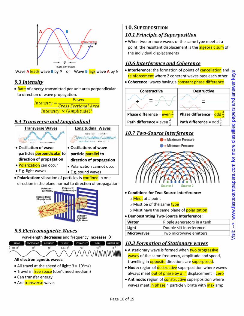
10.7 Two-Source Interference
Conditions for Two-Source Interference:
o Meet at a point
o Must be of the same type
o Must have the same plane of polarization
Demonstrating Two-Source Interference:
Water Ripple generators in a tank
Light Double slit interference
Microwaves Two microwave emitters
10.3 Formation of Stationary waves A stationary wave is formed when two progressive
waves of the same frequency, amplitude and speed,
travelling in opposite directions are superposed.
Node: region of destructive superposition where waves
always meet out of phase by 𝜋, ∴ displacement = zero
Antinode: region of constructive superposition where
waves meet in phase ∴ particle vibrate with max amp
B A
𝜆 =
Vis
it: -
-> w
ww
.fast
exam
pape
rs.c
om fo
r m
ore
clas
sifie
d pa
pers
and
ans
wer
key
s

Page 11 of 15
Neighboring nodes & antinodes separated by 1 2⁄ 𝜆
Between 2 adjacent nodes, particles move in phase and they are out of phase with the next two nodes by 𝜋
Stationary wave at different times:
10.2 Stationary Wave Experiments Stretched String:
String either attached to wall or attached to weight
Stationary waves will be produced by the direct and
reflected waves in the string.
Microwaves:
A microwave emitter placed a distance away from a
metal plate that reflects the emitted wave.
By moving a detector along the path of the wave, the
nodes and antinodes could be detected.
Air Columns:
A tuning fork held at the mouth of
an open tube projects a sound
wave into the column of air in
the tube.
The length can be changed by
varying the water level.
At certain lengths tube, the air
column resonates
This is due to the formation of
stationary waves by the incident
and reflected sound waves at the water surface.
Node always formed at surface of water
10.4 Stationary and Progressive Waves Stationary Waves Progressive Waves
Stores energy Transmits energy Have nodes & antinodes No nodes & antinodes Amplitude increases from node to antinode
Amplitude constant along length of the wave
Phase change of 𝜋 at node No phase change
10.5 Diffraction
Diffraction: the spreading of waves as they pass through
a narrow slit or near an obstacle
For diffraction to occur, the size of the gap should be
equal to the wavelength of the wave.
10.8 Double-Slit Interference
𝜆 =𝑎𝑥
𝐷
Where 𝑎 = split separation
𝐷 = distance from slit to screen
𝑥 = fringe width
Vis
it: -
-> w
ww
.fast
exam
pape
rs.c
om fo
r m
ore
clas
sifie
d pa
pers
and
ans
wer
key
s

Page 12 of 15
10.9 Diffraction Grating
𝑑 sin 𝜃 = 𝑛𝜆
Where 𝑑 = distance between successive slits
= reciprocal of number of lines per meter
𝜃 = angle from horizontal equilibrium
𝑛 = order number
𝜆 = wavelength
Comparing to double-slit to diffraction grating:
Maxima are sharper compared to fringes
Maxima very bright; more slits, more light through
11 ELECTRIC FIELDS
11.1 Concept of Electric Field Can be described as a field of force; it can move charged
particles by exerting a force on them
Positive charge moves in direction of the electric field: they gain EK and lose EP
Negative charge moves in opposite direction of the electric field: they lose EK and gain EP
11.2 Diagrammatic Representation Parallel plates:
Points:
11.3 Electric Field Strength
Force per unit positive charge acting at a point; a vector
Units: 𝑁𝐶−1 or 𝑉𝑚−1
𝐸 =𝐹
𝑞 𝐸 =
𝑉
𝑑
𝐸 is the electric field strength
𝐹 is the force
𝑞 is the charge
𝑉 is potential difference
𝑑 is distance between plates
The higher the voltage, the stronger the electric field
The greater the distance between the plates, the weaker
the electric field
12 CURRENT OF ELECTRICITY Electric current: flow of charged particles
Charge at a point: product of the current at that point
and the time for which the current flows,
𝑄 = 𝐼𝑡
Coulomb: charge flowing per second pass a point at
which the current is one ampere
Volt: joule per coulomb
𝑊 = 𝑉𝑄
𝑃 = 𝑉𝐼 𝑃 = 𝐼2𝑅 𝑃 =𝑉2
𝑅
12.1 p.d. and e.m.f Potential Difference Electromotive Force
work done per unit charge
energy transformed from electrical to other forms
per unit charge
energy transformed from other forms to electrical
12.2 Current-P.D. Relationships Metallic Conductor
Ohmic conductor V/I ratio constant
Filament Lamp
Non-ohmic conductor
Volt ↑, Temp. ↑, Vibration of ions ↑, Collision of ions with e- ↑, Resistance ↑
Vis
it: -
-> w
ww
.fast
exam
pape
rs.c
om fo
r m
ore
clas
sifie
d pa
pers
and
ans
wer
key
s

Page 13 of 15
Thermistor
Non-ohmic conductor
Volt ↑, Temp. ↑, Released e- ↑, Resistance ↓
Semi-Conductor Diode
Non-ohmic conductor
Low resistance in one direction & infinite resistance in opposite
Ohm’s law: the current in a component is proportional
to the potential difference across it provided physical
conditions (e.g. temp) stay constant.
12.3 Resistance Resistance: ratio of potential difference to the current
Ohm: volt per ampere
𝑉 = 𝐼𝑅
Resistivity: the resistance of a material of unit cross-
sectional area and unit length
𝑅 =𝜌𝐿
𝐴
Internal Resistance: resistance to current flow within the
power source; reduces p.d. when delivering current
Voltage across resistor: 𝑉 = 𝐼𝑅
Voltage lost to internal resistance: 𝑉 = 𝐼𝑟
Thus e.m.f.: 𝐸 = 𝐼𝑅 + 𝐼𝑟
𝐸 = 𝐼(𝑅 + 𝑟)
13. D.C. CIRCUITS
13.1 Kirchhoff’s 1st Law Sum of currents into a junction
IS EQUAL TO
Sum of currents out of junction.
Kirchhoff’s 1st law is another statement of the law of
conservation of charge
13.2 Kirchhoff’s 2nd Law Sum of e.m.f.s in a closed circuit
IS EQUAL TO
Sum of potential differences
Kirchhoff’s 2nd law is another statement of the law of
conservation of energy
13.3 Applying Kirchhoff’s Laws Example: Calculate the current in each of the resistors
Using Kirchhoff’s 1st Law:
𝐼3 = 𝐼1 + 𝐼2
Using Kirchhoff’s 2nd Law on loop 𝑨𝑩𝑬𝑭:
3 = 30𝐼3 + 10𝐼1
Using Kirchhoff’s 2nd Law on loop 𝑪𝑩𝑬𝑫:
2 = 30𝐼3
Using Kirchhoff’s 2nd Law on loop 𝑨𝑪𝑫𝑭:
3 − 2 = 10𝐼1
Solve simulataneous equations:
𝐼1 = 0.100 𝐼2 = −0.033 𝐼3 = 0.067
13.3 Deriving Effective Resistance in Series From Kirchhoff’s 2nd Law:
𝐸 = ∑𝐼𝑅
𝐼𝑅 = 𝐼𝑅1 + 𝐼𝑅2
Current constant therefore cancel:
𝑅 = 𝑅1 + 𝑅2
13.4 Deriving Effective Resistance in Parallel From Kirchhoff’s 1st Law:
𝐼 = ∑𝐼
𝐼 = 𝐼1 + 𝐼2 𝑉
𝑅=
𝑉
𝑅1+
𝑉
𝑅2
Voltage constant therefore cancel: 1
𝑅=
1
𝑅1+
1
𝑅2
𝑉 = 𝐼𝑟 − 𝐸
Vis
it: -
-> w
ww
.fast
exam
pape
rs.c
om fo
r m
ore
clas
sifie
d pa
pers
and
ans
wer
key
s

Page 14 of 15
13.5 Potential Divider
A potential divider divides the voltage into smaller parts.
𝑉𝑜𝑢𝑡
𝑉𝑖𝑛=
𝑅2
𝑅𝑇𝑜𝑡𝑎𝑙
Usage of a thermistor at R1:
o Resistance decreases with increasing temperature.
o Can be used in potential divider circuits to monitor
and control temperatures.
Usage of an LDR at R1:
o Resistance decreases with increasing light intensity.
o Can be used in potential divider circuits to monitor
light intensity.
13.6 Potentiometers
A potentiometer is a continuously variable potential
divider used to compare potential differences
Potential difference along the wire is proportional to the
length of the wire.
Can be used to determine the unknown e.m.f. of a cell
This can be done by moving the sliding contact along the
wire until it finds the null point that the galvanometer
shows a zero reading; the potentiometer is balanced
Example: E1 is 10 V, distance XY is equal to 1m. The
potentiometer is balanced at point T which is 0.4m from X.
Calculate E2
𝐸1
𝐸2=
𝐿1
𝐿2
10
𝐸2=
1
0.4
𝐸2 = 4𝑉
14. NUCLEAR PHYSICS
14.1 Geiger-Marsden 𝜶-scattering Experiment: a beam of 𝛼-particles is fired at thin gold foil
Results of the experiment:
o Most particles pass straight through
o Some are scattered appreciably
o Very few – 1 in 8,000 – suffered deflections > 90o
Conclusion:
o All mass and charge concentrated in the center of
atom ∴ nucleus is small and very dense
o Nucleus is positively charged as 𝛼-particles are
repelled/deflected
14.2 The Nuclear Atom Nucleon number: total number of protons and neutrons
Proton/atomic number: total number of protons
Isotope: atoms of the same element with a different
number of neutrons but the same number of protons
14.3 Nuclear Processes
During a nuclear process, nucleon number, proton
number and mass-energy are conserved
Radioactive process are random and spontaneous
Random: impossible to predict and each nucleus has the
same probability of decaying per unit time
Spontaneous: not affected by external factors such as
the presence of other nuclei, temperature and pressure
Evidence on a graph:
o Random; graph will have fluctuations in count rate
o Spontaneous; graph has same shape even at different
temperatures, pressure etc.
Vis
it: -
-> w
ww
.fast
exam
pape
rs.c
om fo
r m
ore
clas
sifie
d pa
pers
and
ans
wer
key
s

Page 15 of 15
14.4 Radiations 𝜶-particle 𝜷-particle 𝜸-ray
Identity Helium nucleus
Fast-moving electron
Electro- magnetic
Symbol 𝐻𝑒24 𝑒−1
0 𝛾
Charge +2 −1 0
Relative Mass
4 1
1840 0
Speed Slow (106 ms-1)
Fast (108 ms-1)
V of Light (3 × 10⁸ ms-1)
Energy Discrete Varying
Stopped by Paper Few mm of aluminum
Few cm of lead
Ionizing power
High Low Very Low
Effect of Magnetic
Deflected slightly
Deflected greater
Undeflected Effect of Electric
Attracted to -ve
Attracted to +ve
14.5 Types of Decays
𝜶-decay: loses a helium proton
𝜷-decay: neutron turns into a proton and an electron,
and the electron is released as a 𝛽-particle
𝜸-decay: a nucleus changes from a higher energy state
to a lower energy state through the emission of
electromagnetic radiation (photons)
Vis
it: -
-> w
ww
.fast
exam
pape
rs.c
om fo
r m
ore
clas
sifie
d pa
pers
and
ans
wer
key
s