1. rc rl-rlc
Upload: bangabandhu-sheikh-mujibur-rahman-science-and-technology-university
Post on 18-Jul-2015
251 views
TRANSCRIPT

Prepared by
Md. Amirul Islam
Lecturer
Department of Applied Physics & Electronics
Bangabandhu Sheikh Mujibur Rahman Science &
Technology University, Gopalganj – 8100


A circuit containing a series combination of a resistor and a
capacitor is called an RC circuit.
Maximum current of the circuit, I0 =Ɛ𝐑
[When, t = 0, Maximum
current flows]
Maximum Charge on Capacitor, Q = CƐ [When t = tf = 5τ]
Reference: Physics II by Robert Resnick and David Halliday, Topic – 28.4, Page – 883

Expression of Charge q(t), voltage VC and current I during
charging phase of an RC circuit:
The voltage across a capacitor cannot
change instantaneously.
Reference: Physics II by Robert Resnick and David Halliday, Topic – 28.4, Page – 883
By applying KVL, We get,
Current through the circuit is the time rate of change of the
charge on the capacitor plates. So,I =
𝐝𝐪
𝐝𝐭
Putting this value of I and after rearranging, we get,

Reference: Physics II by Robert Resnick and David Halliday, Topic – 28.4, Page – 883
This is the equation of charge stored in a capacitor. Voltage
across the capacitor is, VC = q(t) / C
Equation of instantaneous current can be obtained by
differentiating the equation of charge,
Reference: Physics II by Robert Resnick and David Halliday, Topic – 28.4, Page – 883
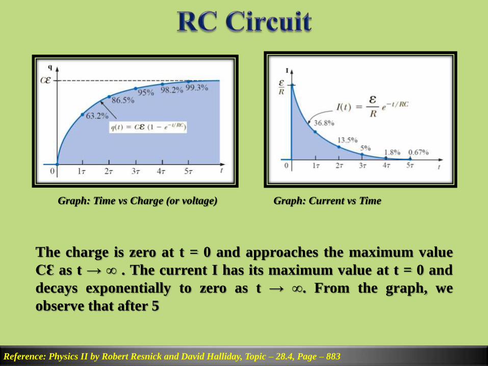
Graph: Time vs Charge (or voltage)
The charge is zero at t = 0 and approaches the maximum value
CƐ as t → ∞ . The current I has its maximum value at t = 0 and
decays exponentially to zero as t → ∞. From the graph, we
observe that after 5
Graph: Current vs Time

Expression of Charge q(t), voltage VC and current I during
discharging phase of an RC circuit:
Reference: Physics II by Robert Resnick and David Halliday, Topic – 28.4, Page – 885
By applying KVL in clockwise direction, we get,
Now, I =𝐝𝐪
𝐝𝐭. Again, when t=0 then q = Q and when t=t then q = q
Reference: Physics II by Robert Resnick and David Halliday, Topic – 28.4, Page – 885
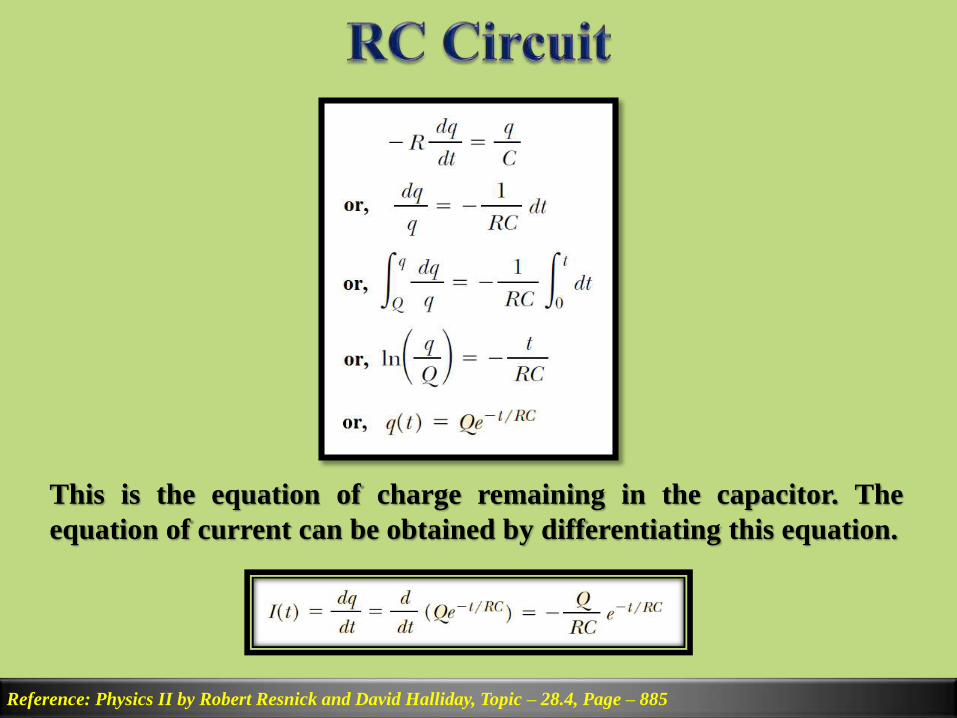
This is the equation of charge remaining in the capacitor. The
equation of current can be obtained by differentiating this equation.
Reference: Circuit Analysis by Robert Boylestad, Figure– 10.24 & 10.39, Page – 395
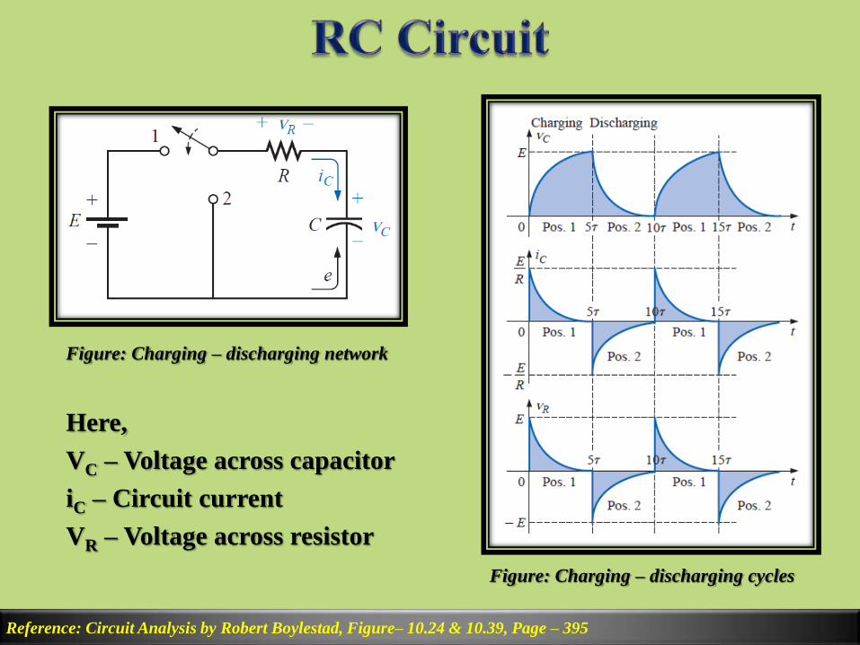
Figure: Charging – discharging network
Here,
VC – Voltage across capacitor
iC – Circuit current
VR – Voltage across resistor
Figure: Charging – discharging cycles

Math. Problem: Find the mathematical expressions for the
transient behavior of vC, iC, and vR for the circuit of Figure
when the switch is moved to position 1.
b. How much time must pass before it can be assumed, for all
practical purposes, that iC ≈ 0 A and vC ≈ E volts?
c. When the switch is placed to position 2, find the mathematical
expressions for the transient behavior of vC, iC, and vR
Reference: Circuit Analysis by Robert Boylestad, , Example – 10.5, Page – 393

Math. Problem: An uncharged capacitor and a resistor are
connected in series to a battery, as shown in Figure. If C = 5μF
and Ɛ = 12V, R = 0.8 MΩ, find the time constant of the circuit,
the maximum charge on the capacitor, the maximum current in
the circuit, and the charge and current as functions of time.
Reference: Physics II by Robert Resnick and David Halliday, Example– 28.11, Page – 887
Time constant, τ = RC = 4s
Maximum charge, Q = CƐ = 60 μC
Maximum Current, I0 =ƐR = 15 μA

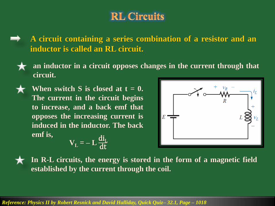
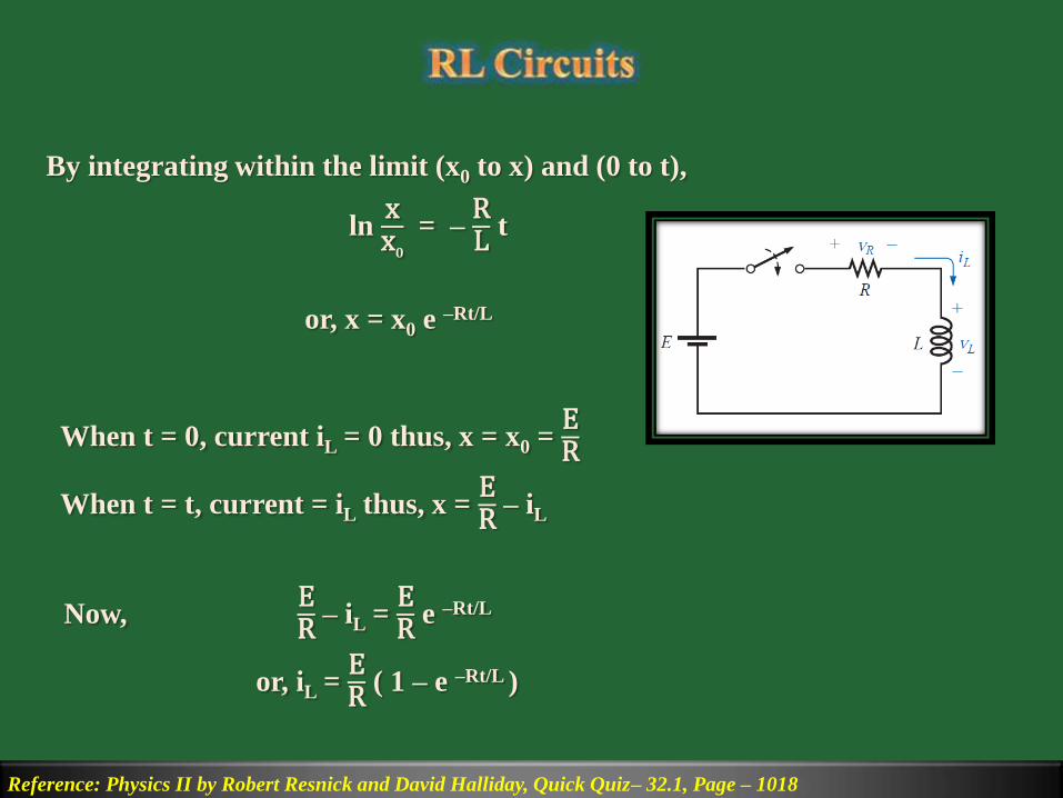
A circuit containing a series combination of a resistor and an
inductor is called an RL circuit.
an inductor in a circuit opposes changes in the current through that
circuit.
Reference: Physics II by Robert Resnick and David Halliday, Quick Quiz– 32.1, Page – 1018
When switch S is closed at t = 0.
The current in the circuit begins
to increase, and a back emf that
opposes the increasing current is
induced in the inductor. The back
emf is,VL = – L
diLdt
In R-L circuits, the energy is stored in the form of a magnetic field
established by the current through the coil.

Expression of transient current iL for the storage cycle of an
RL circuit:
Reference: Physics II by Robert Resnick and David Halliday, Quick Quiz– 32.1, Page – 1018
Here, VL = – LdiLdt
and VR = iL R
By applying KVL we get,
E – VR – VL = 0
or, E – iL R – LdiLdt
= 0
Let,ER
– iL = x then,diLdt
= –dxdt
Now, x +LR
dxdt
= 0
or,dxx
= –RL
dt
Reference: Physics II by Robert Resnick and David Halliday, Quick Quiz– 32.1, Page – 1018
By integrating within the limit (x0 to x) and (0 to t),
lnxx𝟎
= –RL
t
or, x = x0 e –Rt/L
When t = 0, current iL = 0 thus, x = x0 =ER
When t = t, current = iL thus, x =ER
– iL
Now,ER
– iL =ER
e –Rt/L
or, iL =ER
( 1 – e –Rt/L )

For RL circuit time constant, τ =LR
Reference: Physics II by Robert Resnick and David Halliday, Quick Quiz– 32.1, Page – 1019
Thus the equation of current, iL =ER
( 1 – e –t/τ )
When t → ∞ current reaches
final value or steady state
value and then, iL =ER
. That is,
the inductor acts as a short
circuit.
Physically, τ is the time it takes
the current in the circuit to
reach ( 1 – e –1 ) = 0.637 or 63.7%
of its final value ER
.
Figure: Storage Cycle
T𝐡𝐞 𝐞𝐪𝐮𝐚𝐭𝐢𝐨𝐧 𝐨𝐟 𝐕𝐨𝐥𝐭𝐚𝐠𝐞 𝐚𝐜𝐫𝐨𝐬𝐬 𝐢𝐧𝐝𝐮𝐜𝐭𝐨𝐫, VL =ER
e –t/τ
T𝐡𝐞 𝐞𝐪𝐮𝐚𝐭𝐢𝐨𝐧 𝐨𝐟 𝐕𝐨𝐥𝐭𝐚𝐠𝐞 𝐚𝐜𝐫𝐨𝐬𝐬 𝐫𝐞𝐬𝐢𝐬𝐭𝐨𝐫, VR =ER
(1 – e –t/τ )

Find the mathematical expressions for the transient behavior
of iL and vL for the circuit of figure after closing of the switch.
Reference: Circuit Analysis by Robert Boylestad, Example– 12.4, Page – 484

The switch in figure is thrown closed at t = 0
(a) Find the time constant of the circuit.
(b) Calculate the current in the circuit at t = 2 ms
Reference: Physics II by Robert Resnick and David Halliday, Example– 32.3, Page – 1021

RL Circuit – decay Phase:
Reference: Physics II by Robert Resnick and David Halliday, Problem – 18, Page – 1036, 1020
At the instant S2 is closed, S1 is
opened, the battery is no longer part
of the circuit. Stored magnetic energy
inside the inductor starts to decay. By
applying KVL now,
– iL R – LdiLdt
= 0
or,diLiL
= –RLdt
After integrating within the limit (i0 to iL) and (0 to t) we get,
ln iL – ln i0 = –RL
t
or, iL = i0 e – Rt/L = i0 e – t/τ =ER
e – t/τ
So the current through the inductor decrease according to this equation.

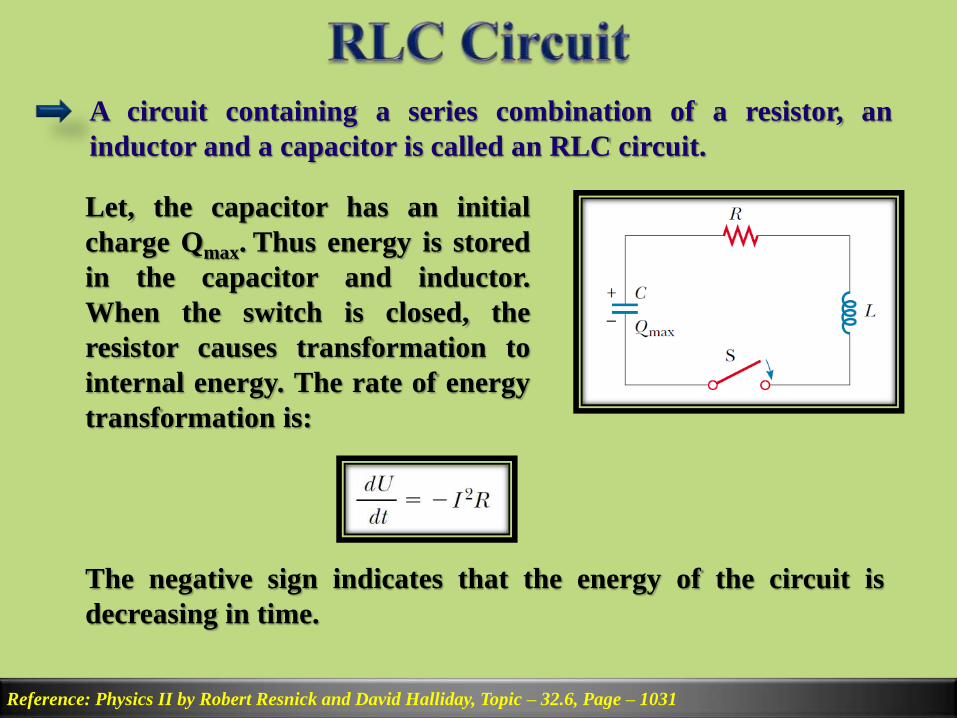
A circuit containing a series combination of a resistor, an
inductor and a capacitor is called an RLC circuit.
Let, the capacitor has an initial
charge Qmax. Thus energy is stored
in the capacitor and inductor.
When the switch is closed, the
resistor causes transformation to
internal energy. The rate of energy
transformation is:
Reference: Physics II by Robert Resnick and David Halliday, Topic – 32.6, Page – 1031
The negative sign indicates that the energy of the circuit is
decreasing in time.

Reference: Physics II by Robert Resnick and David Halliday, Topic – 32.6, Page – 1031
This energy is equal to the energy of capacitor and inductor. Thus,
Solution of this equation is,
ωd is the angular frequency at which the circuit oscillates.
Reference: Physics II by Robert Resnick and David Halliday, Topic – 32.6, Page – 1031
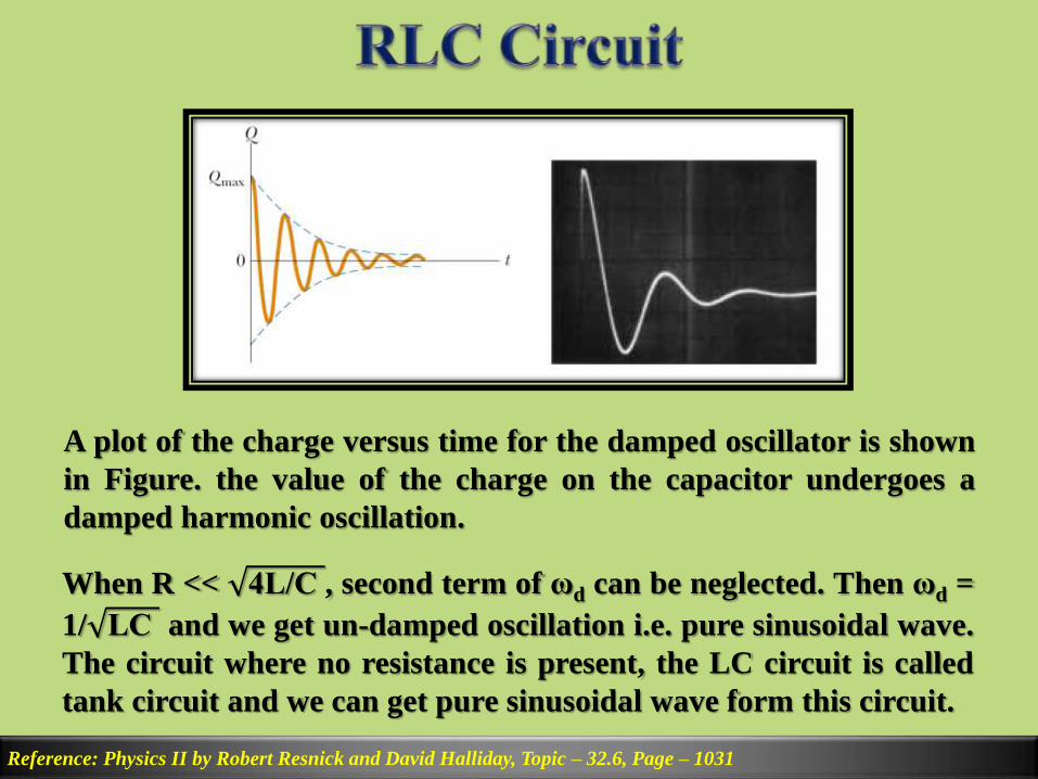
A plot of the charge versus time for the damped oscillator is shown
in Figure. the value of the charge on the capacitor undergoes a
damped harmonic oscillation.
When R << 4L/C , second term of ωd can be neglected. Then ωd =
1/ LC and we get un-damped oscillation i.e. pure sinusoidal wave.
The circuit where no resistance is present, the LC circuit is called
tank circuit and we can get pure sinusoidal wave form this circuit.
