1 version 3 module 8 ethernet switching. 2 version 3 ethernet switching ethernet is a shared media...
Post on 18-Dec-2015
241 views
TRANSCRIPT
1Version 3
Module 8Ethernet Switching

2Version 3
Ethernet Switching
• Ethernet is a shared media– One node can transmit data at a time
• More nodes increases the demands on the available bandwidth – The probability of collisions increases, resulting in
more retransmissions
• A solution to the problem is to segment.
• Segmenting creates more collision domains
3Version 3
Shared Media Environment
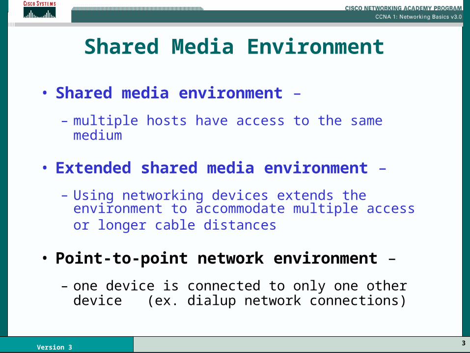
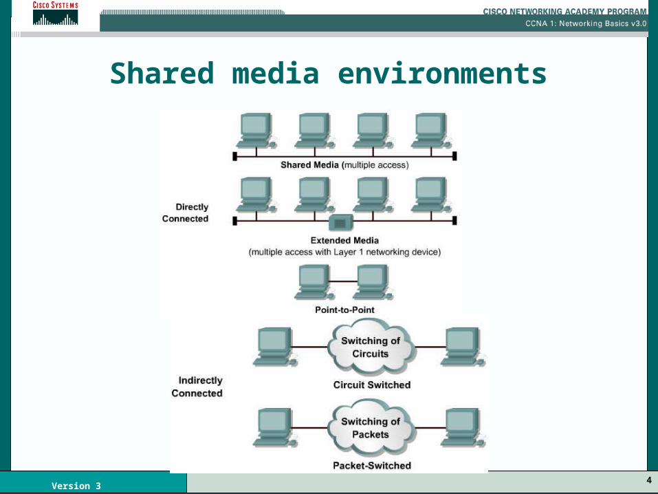
• Shared media environment –
– multiple hosts have access to the same medium
• Extended shared media environment –
– Using networking devices extends the environment to accommodate multiple access or longer cable distances
• Point-to-point network environment –
– one device is connected to only one other device (ex. dialup network connections)
4Version 3
Shared media environments
5Version 3
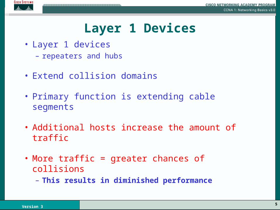
Layer 1 Devices• Layer 1 devices
– repeaters and hubs
• Extend collision domains
• Primary function is extending cable segments
• Additional hosts increase the amount of traffic
• More traffic = greater chances of collisions – This results in diminished performance

6Version 3
Collision Domains
• Collision Domains
– Connected physical network segments where collisions can occur

7Version 3
Collision domains
8Version 3
Collision Domains
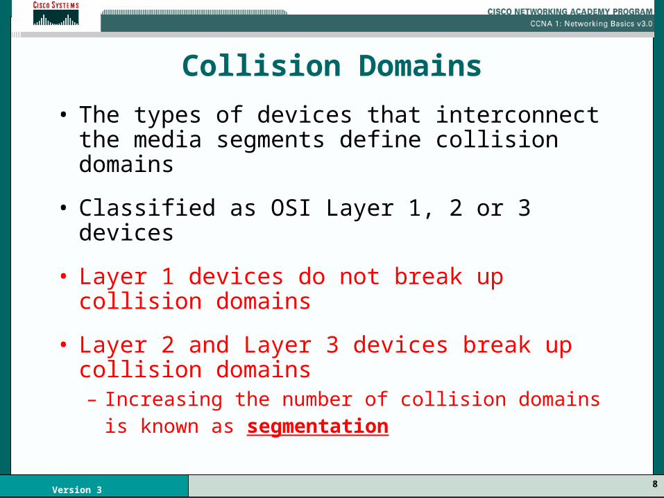
• The types of devices that interconnect the media segments define collision domains
• Classified as OSI Layer 1, 2 or 3 devices
• Layer 1 devices do not break up collision domains
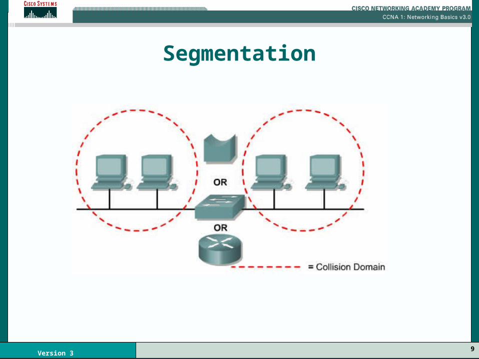
• Layer 2 and Layer 3 devices break up collision domains– Increasing the number of collision domains is
known as segmentation
9Version 3
Segmentation
10Version 3
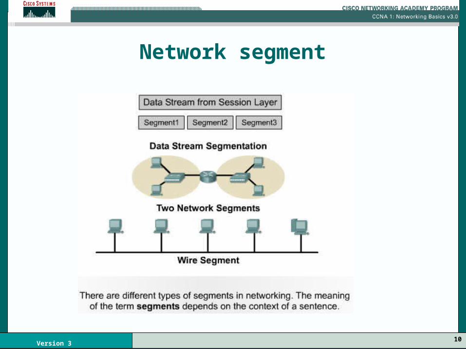
Network segment

11Version 3
Layer 2 Devices
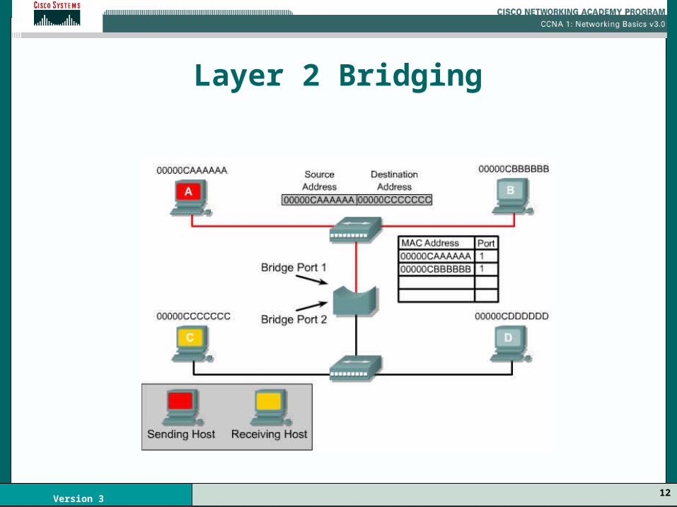
• Layer 2 devices
– Bridges and Switches
– Segments collision domains
– Controls frame propagation using the MAC address
– Tracks the MAC addresses and segment they are on
12Version 3
Layer 2 Bridging

13Version 3
Bridges
• Has only two ports and divides a collision domain into two parts
• Entire network will share the same logical broadcast address space
• All decisions made are based on MAC or Layer 2 addressing
• No effect on the logical or Layer 3 addressing
14Version 3
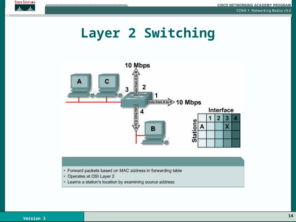
Layer 2 Switching
15Version 3
Switches
• A switch is a fast, multi-port bridge
• Each port creates its own collision domain
• A switch dynamically builds and maintains a Content-Addressable Memory (CAM) table
• The CAM holds all of the necessary MAC information for each port

16Version 3
Switch Operation
• Communication in both directions at once is known as full duplex
• Most switches are capable of supporting full duplex, as are most network interface cards (NICs)
• In full duplex mode, there is no contention for the media.– A collision domain no longer exists– Theoretically, the bandwidth is doubled when
using full duplex

17Version 3
Switch modes
Store and Forward
Cut through

18Version 3
Switch Modes
• Cut-through switching
– A switch transfers the frame as soon as the destination MAC address is received
– lowest latency
– no error checking
19Version 3
Switch Modes
• Store-and-forward switching
– Higher latency
– The switch receives the entire frame before sending it out
– Verifies the Frame Check Sum (FCS)
– Invalid frames are discarded at the switch

20Version 3
Switch Modes
• Synchronous switching– The source port and destination port must
be operating at the same bit rate
• Asynchronous switching – The bit rates are not the same
– The frame must be stored at one bit rate before it is sent out at the other bit rate
– Store-and-forward must be used

21Version 3
Switch Modes
• Asymmetric switching
– Switched connections between ports of unlike bandwidths
– Asymmetric switching is optimized for client/server
– A server requires more bandwidth dedicated to the server port to prevent a bottleneck at that port
22Version 3
Layer 2 Broadcasts
• Ethernet Broadcasts
– When a node needs to communicate with all hosts on the network
– A broadcast frame with a destination MAC address 0xFFFFFFFFFFFF is sent
– The network interface card (NIC) of every host must respond

23Version 3
Layer 2 Broadcasts
• The three sources of broadcasts and multicasts:
– Workstations
– Routers
– Multicast Applications

24Version 3
Layer 3 Devices
• Layer 3 devices
– Routers
– Do not forward collisions
– Breaks up collision domains
– Broadcast domains are controlled

25Version 3
Broadcast domain
26Version 3
Broadcast Domain
• Broadcast Domain – A grouping of collision domains
– Broadcasts have to be controlled at Layer 3 devices
– Layer 2 and Layer 1 devices do not control broadcasts
27Version 3
Data Flow
• Layer 2 devices filter data frames based on the destination MAC address
– A Layer 2 device will forward the frame unless something prevents it from doing so
• Layer 3 devices filter data packets based on IP destination address
– A Layer 3 device will not forward the frame unless it has to
– Layer 3 device creates multiple collision and broadcast domains
28Version 3
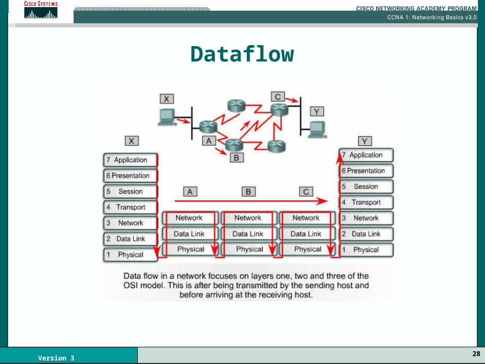
Dataflow
29Version 3
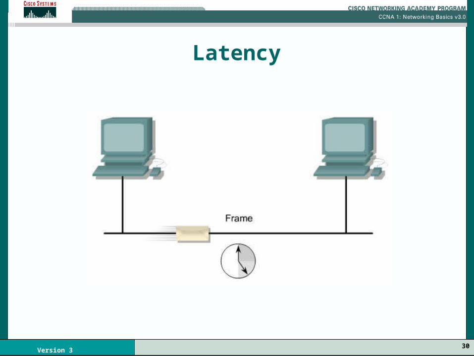
Latency
The delay between the time a frame leaves the source device and the time the frame reaches its destination
• The following conditions can cause delays:
– Physical media – Circuit delays
• Electronics that process the signal along the path – Software delays
• Decisions that must be made to implement switching and protocols
– Delays caused by the content of the frame• Destination MAC address has to be read
30Version 3
Latency