1 welcome to the international right of way association’s course 900 principles of real estate...
TRANSCRIPT

1
Welcome to the International Right of Way
Association’s
Course 900Principles of Real Estate
Engineering
900-PT – Revision 2 –02.25.07.CA

2
Introductions
Who we are…What we do…
Where we do it…
How long we’ve been doing it…
Our goals for the course...

3
Objectives (1)
At the conclusion of the course,
you will be able to…• Describe the basic principles of engineering drawings
• Understand and interpret information on plans
• Use an engineer’s scale and a metric (rational) scale to determine distances

4
Objectives (2)
At the conclusion of the course,
you will be able to…
• Identify types of highway curves
• Discuss the engineering effectsof a project on a property
• Understand the background of property descriptions

5
Objectives (3)
At the conclusion of the course,
you will be able to…• Describe the basic features of property descriptions
• Identify the most common systems and methods of property descriptions
• Write and plot property descriptions using various methods

6
Housekeeping

7
Schedule (1)
8:00 - 8:30 Introductions, Etc.
8:30 - 12:00 Use of Engineering Drawings and Plan Development
1:00 - 1:30 Utility Alignment Plans
1:30 - 2:30 Highway Construction Plans
2:45 - 3:45 Right of Way Plans
3:45 - 4:15 Interpreting Engineering Plans
4:15 - 4:45 Bearings
4:45 - 5:00 Recap Day One

8
Schedule (2)
8:00 - 8:15 Recap Day One/Introduce Day Two
8:15 - 2:00 Property Descriptions
2:15 - 2:45 Summary of Property Descriptions
2:45 - 3:00 Summary and Review
3:00 - 5:00 Exam

9
Plans Used By...
Engineers
Appraisers
Negotiators
Lawyers
Others

10
Three-View Concept(Three perpendicular views)
Plan View: Top view (length and width)
Profile View: Side view (length and height)
Cross-section view: End view (width and height)

11
Plan View (Top view)
Horizontal alignment
Topography
North arrow
Symbols

12
Scales (1)
Metric

13
Scales (2)
Imperial
Architect

14
Exercise No. 1

15
Stations
Stations: 100m or 1,000m intervals on centreline. Intermediate points are indicated as a “plus”.
Station equation: Stations not continuous. A point has two station numbers, one ahead and one back.

16
100 Metre Station
20 m20 m 20 m
20 m 20 m 20 m20 m
100 m Sta. 328.08’
Sta 0+00
Sta 0+20
Sta 0+40
Sta 0+60
Sta 0+80
Sta 1+00
Sta 1+20
Sta 1+40
Scale 1:1000

17
Exercise No. 2

18
Offsets
Perpendicular distances
Left or right of the centreline
Locate a point by station and offset

19
Exercise No. 3

20
Curves (1)
Simple curve
Reverse curve

21
Curves (2)
Compound curve
Spiral curve

22
ContoursLines of equal elevation
Shape and slopeof land
Close lines = steep slope
Point up stream
Annotation faces uphill (convention)

23
Pipeline

24
Overhead

25
Highway

26
Profile View (Side view)
Centreline elevations
Existing and proposed
Exaggerated vertical scale
27
Datum/BenchmarkDatum
Basis for elevation reference
Example: Mean sea level
Benchmark
Known elevation point
Used as reference

28
Profile Grade Line
Proposed centreline elevations
Percent grade
Rate of elevation change (%)
Rise (+) or Fall (-)

29
Highway Curves
Parabolic (sag or crest)
P.V.C.
P.V.I.
P.T.
L

30
Pipeline

31
Overhead

32
Highway
33
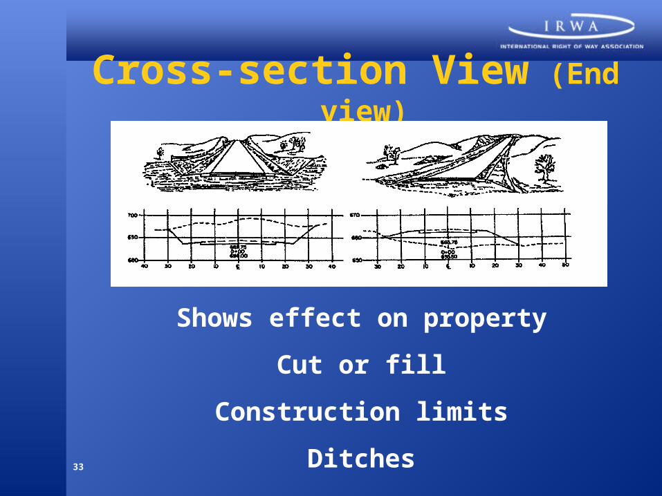
Cross-section View (End view)
Shows effect on property
Cut or fill
Construction limits
Ditches

34
Superelevation
Slope pavement surface
To counter centrifugal force

35
Exercise No. 6

36
Pipeline/Powerline
Trench depth
Trench width
Pipe diameter
Backfill details
Bedding details
Height and width
Wire spacing
Brace detail
Clearance
Foundation

37
Highway

38
Overhead Transmission Line
39
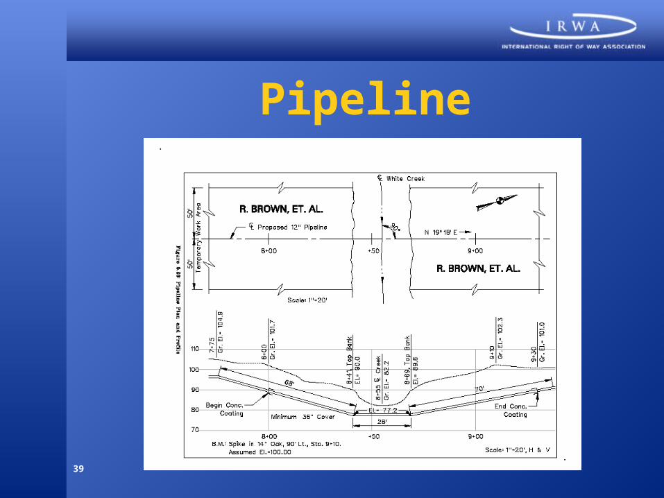
Pipeline

40
Title SheetArea Map
Agency Name
Project Name
Project No.
Utilities List
Layout Map Sheet Index

41
Schematic Plan/Typical Sections
Schematic Plan: Overall scope of project.
Typical Sections: Finished shapeand dimensions. Pavement type and thickness. Superelevation details.

42
General Notes/General Summary
General Notes: Clarify construction. Additional information.
General Summary: Total quantities. Cost estimate. Bid preparation.

43
Plan-Profile Sheets
Plan View: North arrow. Centreline and station. Detailed information.
Profile View: Centreline elevations. Exaggerated vertical scale.

44
Cross-sections (1)
Existing and proposed elevations
100m intervals
Looking ahead, up sheet

45
Cross-sections (2)

46
Right of Way PlanArea Map
Agency Name
Project Name
Project No.
Utilities List
Layout Map Sheet Index

47
Centreline Plan
Major geographic features
Filed for record

48
Property MapsParcel acquisition details
Major land details

49
Summary Sheet
Tabulation of all parcels
Ownership index
Areas acquired

50
Detail SheetIndividual property planProperty rights acquired

51
Bearings

52
Exercise No. 10 (1)
N 36o 30’ E S 36o 30’W
S 43o 30’ W N 43o 30’E
S 71o 00’ E N 71o 00’ W
N 57o 00’ W S 57o 00’E

53
Exercise No.10 (2)
N 68o 00’ E
S 48o 45’ W
S 25o 00’ E
N 28o 00’ W

54
Recap Day One

55
Day Two

56
Property Descriptions (1)
Dominion Lands Survey System
Plane coordinate system
Metes and bounds
Point
Centreline
Lot and block
Subdivision

57
Property Descriptions (2)
Caption/Preamble
Body
Reservations/Exceptions
58
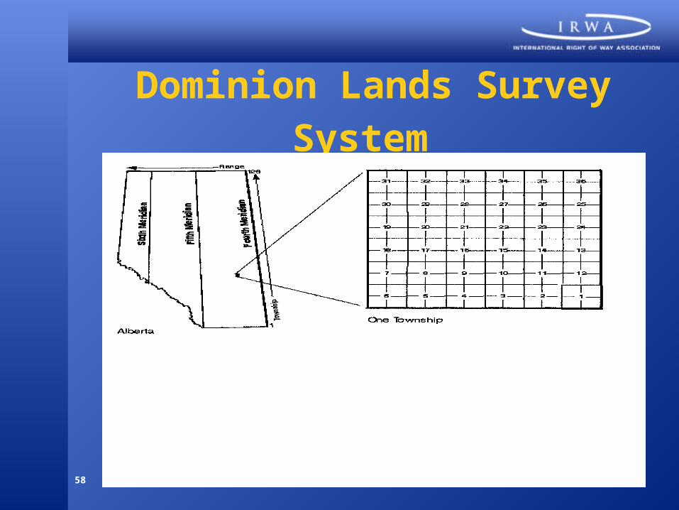
Dominion Lands Survey System

59
Exercise No. 11

60
Sections36 section in a township
Numbered1 through 36
Beginningin SE corner
Approximately 1 mile square
640 acres

61
Section Parts (1)

62
Section Parts (2)

63
Exercise No. 12 (1)

64
Exercise No. 12 (2)

65
Plane Coordinate System*
Well monumented
Points located by coordinates
“X” Easting
“Y” Northing
High degree of accuracy
* Not currently permitted in any province or territory. However, experiments underway.

66
Plane Coordinate System (2)

67
Plane Coordinate System (3)

68
Plane Coordinate System (4)

69
Metes and Bounds
Metes: Measurements of boundary.
Bounds: Adjoining property owner.
Monuments: Natural and artificial.

70
Angles

71
Property Descriptions
Begins at a known point
Enables future location
Point of commencement (P.O.C.)
Point of beginning (P.O.B.)
Description (call for each line [clockwise],
bearing and length, must close)

72
Magnetic North Pole

73
Exercise No. 13
74
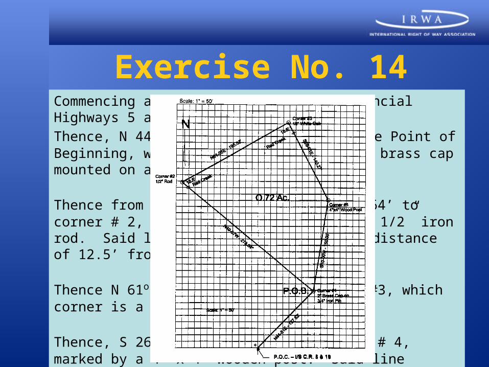
Exercise No. 14Commencing at the intersection of Provincial Highways 5 and 19;
Thence, N 44o 51’ E - 127.92’ to the true Point of Beginning, which point is a 2” diameter brass cap mounted on a 3/4” iron pipe;
Thence from the POB, N 49o 07’ W - 273.64’ to corner # 2, which corner is marked by a 1/2” iron rod. Said line crosses Red Creek at a distance of 12.5’ from corner #2;
Thence N 61o 05’ E - 195.83’ to corner #3, which corner is a 10” white oak tree;
Thence, S 26o 01’ E - 140.27’ to corner # 4, marked by a 4” x 4” wooden post. Said line crosses Red Creek at 18.5’ from corner #3.
Thence, S 10o 00’ W - 150.00’ to the Point of Beginning. Containing 0.72 acres, more or less.

75
Point DescriptionHighway right of way
Centreline - recorded
Stations are basis
Each point described by station and offset

76
Station and Offset

77
Exercise No. 15
Beginning at a point 25 feet left of highway station 210+98, which point is in the northern right of way line of Provincial Highway 47, as recorded in _________:
Thence, leaving said right of way line, and going to a point 54 feet left of station 211 +05; Thence, to a point 65 feet left of station 211 +50; Thence, to a point 57 feet left of station 212+07; Thence, to a point in the aforesaid right of way line, 25 feet left of 212+13; Thence, along said right of way back to the Point of Beginning.

78
Centreline Description
Used by utilities
Acquisition of right of way strips
Reference is stations
Referenced, recorded
Width of right of way specified

79
Exercise No. 16 (1)
An easement for the construction, maintenance, use and operation of utility services, said easement situate, lying and being in Block 4 of Rolling Trails Addition, as shown on a plan thereof, recorded in __________, and being more particularly described as follows:

80
Exercise No. 16(2)
Commencing at the intersection of the easterly right of way line of First Street and the northerly right of way line of Able Drive:
Thence, in a northwest direction, along the easterly right of way line of First Street, a distance of 100’ to the true Point of Beginning for the centreline of the easement:
Thence, N 59°58' E, 193.82’ to a point;
Thence, N 84°05' E, 301.47’ to a point in the westerly right of way line of Second Street. Said point is 215’ in a northerly direction from the intersection of said right of way line with the northerly right of way line of Able Drive.
Said easement having a 20’ uniform width, 10’ being on each side of the above described centreline. Containing 9,906 sq. ft.

81
Subdivision Plan
Land subdivided into lots
Named, plotted and recorded
Description (lot number, subdivision name,
location or record plan)

82
Lot and Block
Urban areas
Block plotted and recorded
Description (lot number and block name,name of the political subdivision,
location or registered plan)

83
Exercise No. 17

84
Metes and Bounds - Lot and Block
Caption: A portion of Lot 7, Block 4, as shown on the map entitled “Tract 426” filed in the office of __________, on May 5, 1997, in Map Book 9, Page 78, described as follows.
Body: Beginning at the northwesterly corner of Lot 7; thence along the northerly line of said lot S 88o, 50.00’; thence E, 50.00’ to the easterly line of said tract; thence along last said line S 1o 10’ W, 21.50’; thence S 72o 30’ W, 55.00’ to the westerly line of said lot; thence along last said line N 1o 10’ E, 39.12’ to the POB.
Area: Containing 1,516 square feet, more or less.

85
Metes and Bounds - Dominion Lands Survey System
Caption: A portion of the SW 1/4 of Section 3, T3N, R2W, MDB&M, described as follows.
Body: Beginning at the southeasterly corner of the SW 1/4 of Section 3; thence along the southerly line of said Section 3, S 89o W, 1,200’; thence N 36o E, 2,000’ to the easterly line of the SW 1/4 of said section; thence along the last said line S 1o E, 1,600’ to the POB.
Area: Containing 22 acres.

86
Metes and Bounds -Metes and Bounds
Caption: A portion of the parcel of land described in the deed to E. C. Jones, recorded February 1, 1960 in Volume 1620, Page 12, described as follows.
Body: Beginning at a point on the southerly line of said parcel, distance thereon N 88o E, 100.00’ from the southwest corner of said parcel; thence N 2o W, 60.00’; thence N 88o E, 60.00’; thence S 2o E, 60.00’ to said southerly line; thence along said line, S 88o W, 60.00’ to the POB.
Area: Containing 360 square feet, more or less.

87
Summary
Property descriptions
Essential elements of a right of way
Proper wording critical

88
MethodsDominion Lands Survey System
Plane coordinate system
Metes and bounds
Point
Centreline
Lot and block
Subdivision

89
Objectives (1)
Now, you are able to…
• Describe the basic principlesof engineering drawings
• Understand and interpret information on plans
• Use an engineer’s scale anda metric (rational) scale todetermine distances

90
Objectives (2)
Now, you are able to…
• Identify types of highway curves
• Discuss the engineering effectsof a project on a property
• Understand the background of property descriptions

91
Objectives (3)
Now, you are able to…
• Describe the basic featuresof property descriptions
• Identify the most common systems and methods of property descriptions
• Write and plot property descriptions using various methods

92
Thank you!
900-PT – Revision 2 –02.25.07.CA